JP5213613B2 - Image processing apparatus, image processing method, imaging apparatus, and program - Google Patents
Image processing apparatus, image processing method, imaging apparatus, and program Download PDFInfo
- Publication number
- JP5213613B2 JP5213613B2 JP2008248070A JP2008248070A JP5213613B2 JP 5213613 B2 JP5213613 B2 JP 5213613B2 JP 2008248070 A JP2008248070 A JP 2008248070A JP 2008248070 A JP2008248070 A JP 2008248070A JP 5213613 B2 JP5213613 B2 JP 5213613B2
- Authority
- JP
- Japan
- Prior art keywords
- group
- image
- vector detection
- groups
- determined
- Prior art date
- Legal status (The legal status is an assumption and is not a legal conclusion. Google has not performed a legal analysis and makes no representation as to the accuracy of the status listed.)
- Expired - Fee Related
Links
Images


Classifications
-
- H—ELECTRICITY
- H04—ELECTRIC COMMUNICATION TECHNIQUE
- H04N—PICTORIAL COMMUNICATION, e.g. TELEVISION
- H04N5/00—Details of television systems
- H04N5/14—Picture signal circuitry for video frequency region
- H04N5/144—Movement detection
- H04N5/145—Movement estimation
-
- G—PHYSICS
- G06—COMPUTING; CALCULATING OR COUNTING
- G06T—IMAGE DATA PROCESSING OR GENERATION, IN GENERAL
- G06T7/00—Image analysis
- G06T7/20—Analysis of motion
- G06T7/215—Motion-based segmentation
-
- H—ELECTRICITY
- H04—ELECTRIC COMMUNICATION TECHNIQUE
- H04N—PICTORIAL COMMUNICATION, e.g. TELEVISION
- H04N23/00—Cameras or camera modules comprising electronic image sensors; Control thereof
- H04N23/60—Control of cameras or camera modules
- H04N23/68—Control of cameras or camera modules for stable pick-up of the scene, e.g. compensating for camera body vibrations
-
- G—PHYSICS
- G06—COMPUTING; CALCULATING OR COUNTING
- G06T—IMAGE DATA PROCESSING OR GENERATION, IN GENERAL
- G06T2207/00—Indexing scheme for image analysis or image enhancement
- G06T2207/10—Image acquisition modality
- G06T2207/10016—Video; Image sequence
-
- G—PHYSICS
- G06—COMPUTING; CALCULATING OR COUNTING
- G06T—IMAGE DATA PROCESSING OR GENERATION, IN GENERAL
- G06T2207/00—Indexing scheme for image analysis or image enhancement
- G06T2207/20—Special algorithmic details
- G06T2207/20021—Dividing image into blocks, subimages or windows
Landscapes
- Engineering & Computer Science (AREA)
- Multimedia (AREA)
- Signal Processing (AREA)
- Computer Vision & Pattern Recognition (AREA)
- Physics & Mathematics (AREA)
- General Physics & Mathematics (AREA)
- Theoretical Computer Science (AREA)
- Image Analysis (AREA)
- Studio Devices (AREA)
- Compression Or Coding Systems Of Tv Signals (AREA)
- Adjustment Of Camera Lenses (AREA)
Description
本発明は、ビデオカメラなどによって撮影された動画像のぶれを補正する装置等に適用する、画像処理装置及び方法の技術に関するものである。 The present invention relates to a technique of an image processing apparatus and method applied to an apparatus or the like that corrects blurring of a moving image taken by a video camera or the like.
ビデオカメラなどの動画像を撮影する撮像装置においては、特にレンズを望遠側にズームしたときに、手ぶれにより画像がぶれることが問題となる。このような手ぶれによる画像のぶれを防止するために、従来より撮影した画像信号から画像の動きベクトルを検出し、この動きベクトルに基づいて画像のぶれを補正する技術が提案されている。この補正技術を搭載した撮像装置が特許文献1(特開平6−133298号公報)に記載されている。 In an imaging apparatus such as a video camera that captures a moving image, there is a problem that the image is blurred due to camera shake, particularly when the lens is zoomed to the telephoto side. In order to prevent such image blur due to camera shake, a technique has been proposed in which a motion vector of an image is detected from an image signal taken in the past and the image blur is corrected based on the motion vector. An imaging apparatus equipped with this correction technique is described in Japanese Patent Laid-Open No. 6-133298.
また、画像の動きベクトルを検出する方法としては、従来より、相関演算に基づく相関法やブロックマッチング法等が知られている。 As a method for detecting a motion vector of an image, a correlation method based on a correlation calculation, a block matching method, and the like are conventionally known.
ブロックマッチング法では、入力された画像信号を複数の適当な大きさ(例えば8画素×8ライン)のブロック領域(以下、ベクトル検出領域とする)に分割する。そして、このベクトル検出領域単位で前のフィールド(またはフレーム)の一定範囲の画素との差を計算し、この差の絶対値の和が最小となる前のフィールド(またはフレーム)のベクトル検出領域を探索する。そして、画面間の相対的なずれが、そのベクトル検出領域の動きベクトルを表している。 In the block matching method, an input image signal is divided into a plurality of block areas (hereinafter referred to as vector detection areas) having an appropriate size (for example, 8 pixels × 8 lines). Then, the difference between the previous field (or frame) and a certain range of pixels is calculated in units of the vector detection area, and the vector detection area of the previous field (or frame) that minimizes the sum of the absolute values of the differences is calculated. Explore. And the relative shift | offset | difference between screens represents the motion vector of the vector detection area.
また、マッチング演算については、尾上守夫等により、情報処理Vol.17,No.7,p.634〜640 July 1976 で詳しく論じられている。 For matching operations, Morio Onoe et al., Information Processing Vol. 17, no. 7, p. 634-640 July 1976.
次に、ブロックマッチング法を用いた従来の動きベクトル検出法の一例を、図面を用いて説明する。図15は従来の動きベクトル検出法によりぶれを防止する装置の概略ブロック図である。 Next, an example of a conventional motion vector detection method using the block matching method will be described with reference to the drawings. FIG. 15 is a schematic block diagram of an apparatus for preventing shake by a conventional motion vector detection method.
まず動きベクトルの検出対象となる画像信号(フィールドまたはフレーム)が画像メモリ101及び空間周波数成分を抽出するフィルタ102に加えられる。画像メモリ101は画像信号を一時記憶する。フィルタ102は画像信号から動きベクトル検出に有用な空間周波数成分を抽出する。即ち、画像信号の低空間周波数成分及び高空間周波数成分を除去する。
First, an image signal (field or frame) to be detected as a motion vector is applied to the image memory 101 and a
フィルタ102を通過した画像信号は2値化回路103に加えられる。2値化回路103は画像信号を、ゼロレベルを基準として2値化する。具体的には出力信号の符号ビットを出力する。
The image signal that has passed through the
2値化された画像信号は相関演算回路104及び1フィールド期間遅延手段としてのメモリ105に加えられる。相関演算回路104には更にメモリ105から前フィールドの画像信号が加えられている。
The binarized image signal is added to the correlation calculation circuit 104 and the
相関演算回路104はブロックマッチング法に従い、上記のように適当な大きさのベクトル検出領域に画像領域を分割し、ベクトル検出領域単位に時間的に連続する画像データ間の相関演算を行い、その結果の相関値を動きベクトル検出回路106に加える。動きベクトル検出回路106は算出された相関値からベクトル検出領域単位の動きベクトルを検出する。具体的には相関値が最小となる前フィールドのベクトル検出領域を探索し、その相対的なずれを動きベクトルとしている。 In accordance with the block matching method, the correlation calculation circuit 104 divides the image area into vector detection areas of an appropriate size as described above, and performs correlation calculation between temporally continuous image data in units of vector detection areas. Are added to the motion vector detection circuit 106. The motion vector detection circuit 106 detects a motion vector for each vector detection area from the calculated correlation value. Specifically, the vector detection area of the previous field that minimizes the correlation value is searched, and the relative deviation is used as the motion vector.
このベクトル検出領域単位の動きベクトルは動きベクトル決定回路107に加えられる。動きベクトル決定回路107はベクトル検出領域単位の動きベクトルから全体の動きベクトルを決定する。具体的には、ベクトル検出領域単位の動きベクトルの中央値または平均値を画像全体の動きベクトルとしている。
The motion vector for each vector detection area is added to the motion
動きベクトル決定回路107は全体の動きベクトルをメモリ読み出し制御回路108に加える。メモリ読み出し制御回路108は上記の全体の動きベクトルに応じて画像の動きが相殺されるように画像メモリ101の読み出し位置を制御し、画像メモリ101からぶれが補正された画像信号が出力される。
The motion
しかしながら、上記の方法では、画像中に移動被写体がある場合、例えば検出された動きベクトルの平均値を全体の動きベクトルにすると、画像中の移動被写体の動きが混入してしまう。その結果、移動被写体が画面内の元の位置にとどまるように画像メモリの読み出し位置が変化し、それにより本来動きがないはずである画面内の領域の位置が変化するため、画面が移動被写体に引っ張られたような動きをしてしまう。 However, in the above method, when there is a moving subject in the image, for example, if the average value of the detected motion vectors is set as the entire motion vector, the movement of the moving subject in the image is mixed. As a result, the read position of the image memory changes so that the moving subject stays at the original position in the screen, and the position of the area in the screen that should not move is changed, so the screen becomes a moving subject. It moves as if it was pulled.
本違和感回避のためには、移動物の領域への追従を防止し、背景の動きベクトルのみに追従するよう制御する必要がある。そこで特許文献2(特開2007−235769号公報)のように、画面内に移動物が存在する場合に、領域の多数を占めるベクトルグループを検出し、それによって背景と移動物を見分けることによって対してぶれ補正を行うという方法が提案されている。
しかしながら特許文献2の方法は、1フレームごとにグループ中のベクトル領域の離散度合いの情報を用いる移動物領域判定であるため、移動物領域判定が時系列で関連付けられていない。それゆえ、背景と移動物の離散度合いの大きさが同程度であるときや移動物が徐々に大きくなる場合などは、手ブレ補正する領域を誤判定したり、ぶれ補正の対象となるグループが切り替わったりしてしまうという課題があった。
However, since the method of
そこで本発明は、上述した課題に鑑みて、フレームごとでの移動物領域判定において、時系列で関連付けを行うことによって、撮影中に誤判定しないよう撮像装置のぶれと移動物の移動による動きベクトルとの識別を精度良く行うことを目的とする。特に移動物の大きさが大きい場合や、移動物が徐々に大きくなる場合にも、誤判定しないよう、撮像装置のぶれにより生じる動きベクトルと移動物の移動による動きベクトルとの識別を精度良く行うことを目的とする。 Therefore, in view of the above-described problems, the present invention relates to a motion vector based on movement of an imaging device and movement of a moving object so as not to make an erroneous determination during shooting by performing time-series association in moving object region determination for each frame. The purpose of this is to accurately identify the above. In particular, when the size of a moving object is large or when the moving object gradually increases, the motion vector generated by the shake of the imaging apparatus and the motion vector due to the movement of the moving object are accurately identified so as not to make an erroneous determination. For the purpose.
上述した課題を解決し、目的を達成するために、本発明に係わる画像処理装置は、時間的に連続するフィールドを処理する画像処理装置であって、それぞれのフィールドに対して、複数のベクトル検出領域で動きベクトルを検出するベクトル検出手段と、フィールドごとに、前記ベクトル検出手段にて検出した前記動きベクトルに基づいて前記ベクトル検出領域をグループ化したグループ領域を設定する設定手段と、異なるフィールド間で前記グループ領域同士を比較することで、当該フィールド間で対応するグループ領域を判定する判定手段とを有することを特徴とする。 In order to solve the above-described problems and achieve the object, an image processing apparatus according to the present invention is an image processing apparatus that processes temporally continuous fields, and a plurality of vector detections are performed for each field. Vector detection means for detecting a motion vector in a region, setting means for setting a group region obtained by grouping the vector detection regions based on the motion vector detected by the vector detection device for each field, and between different fields And determining means for comparing the group areas to determine a corresponding group area between the fields.
さらに、本発明の別の実施形態に係わる画像処理装置は、複数の画像のそれぞれに複数のベクトル検出領域を設定し、当該画像間の相関から、設定されたそれぞれのベクトル検出領域において動きベクトルを検出する検出手段と、前記それぞれのベクトル検出領域にて検出される動きベクトルに基づいて、前記それぞれのベクトル検出領域をグループに分類する領域分類手段と、前記領域分類手段により分類された結果、前記それぞれのベクトル検出領域が複数のグループに分類された場合に、ある画像の当該複数のグループから基準となる1つのグループを決定し、他の画像の複数のグループのうち、前記他の画像の前記複数のグループの重心と前記ある画像の決定された1つのグループの重心との距離の差分が最も小さいグループを、前記ある画像の基準となるグループとして決定する決定手段と、前記他の画像の前記決定手段によって決定されたグループと前記ある画像の前記決定手段によって決定されたグループとの間のずれを修正するずれ修正手段を有し、前記決定工程では、他の画像の複数のグループのうち、前記他の画像の前記複数のグループの重心と前記決定工程によって決定された1つのグループの重心との距離の差分が所定値より小さい場合には、他の画像の複数のグループのうち、前記他の画像の前記複数のグループそれぞれのベクトル検出領域のばらつき度合いを示す値と前記ある画像のグループに属するベクトル検出領域のばらつき度合いを示す値との差分が最も小さいグループを、前記ある画像の基準となるグループとして決定することを特徴とする。 Furthermore, an image processing apparatus according to another embodiment of the present invention sets a plurality of vector detection regions for each of a plurality of images, and calculates a motion vector in each of the set vector detection regions from the correlation between the images. Detection means for detecting, area classification means for classifying the respective vector detection areas into groups based on motion vectors detected in the respective vector detection areas, and a result of classification by the area classification means, When each vector detection area is classified into a plurality of groups, one group serving as a reference is determined from the plurality of groups of a certain image, and the group of the other images among the plurality of groups of the other images is determined. The group having the smallest difference in the distance between the centroids of a plurality of groups and the centroid of one group determined in the certain image is A determination unit that determines a group serving as a reference of an image, and a correction for correcting a shift between the group determined by the determination unit of the other image and the group determined by the determination unit of the certain image have a means, in the determination step, among the groups of other images, the difference of the distance between one group of centroids determined by centroid and the determining step of the plurality of groups of said other images When the value is smaller than the predetermined value, a value indicating the degree of variation in the vector detection area of each of the plurality of groups of the other image and a vector detection area belonging to the group of the certain image among the plurality of groups of the other image. groups smallest difference between the value indicating the variation degree, and determines as a group to be a reference of the certain image
さらに、本発明の別の実施形態に係わる画像処理装置は、複数の画像のそれぞれに複数のベクトル検出領域を設定し、当該画像間の相関から、設定されたそれぞれのベクトル検出領域において動きベクトルを検出する検出手段と、前記それぞれのベクトル検出領域にて検出される動きベクトルに基づいて、前記それぞれのベクトル検出領域をグループに分類する領域分類手段と、前記領域分類手段により分類された結果、前記それぞれのベクトル検出領域が複数のグループに分類された場合に、ある画像の当該複数のグループから基準となる1つのグループを決定し、他の画像の複数のグループのうち、当該他の画像の前記複数のグループのベクトル検出領域のばらつき度合いを示す値と前記ある画像の決定された1つのグループのベクトル検出領域のばらつき度合いを示す値との差分が最も小さいグループを、前記ある画像の基準となるグループとして決定する決定手段と、前記他の画像の前記決定手段によって決定されたグループと前記ある画像の前記決定手段によって決定されたグループとの間のずれを修正するずれ修正手段を有し、前記決定手段は、他の画像の複数のグループのうち、前記他の画像のベクトル検出領域のばらつき度合いを示す値と前記決定手段によって決定された前記ある画像1つのグループのベクトル検出領域のばらつき度合いを示す値との差分が所定値より小さい場合には、他の画像の複数のグループのうち、前記他の画像の前記複数のグループそれぞれのベクトル検出領域の重心と前記ある画像の前記決定手段によって決定された1つのグループに属するベクトル検出領域の重心との距離の差分が最も小さいグループを、前記ある画像の基準となるグループとして決定することを特徴とする。 Furthermore, an image processing apparatus according to another embodiment of the present invention sets a plurality of vector detection regions for each of a plurality of images, and calculates a motion vector in each of the set vector detection regions from the correlation between the images. Detection means for detecting, area classification means for classifying the respective vector detection areas into groups based on motion vectors detected in the respective vector detection areas, and a result of classification by the area classification means, When each vector detection region is classified into a plurality of groups, one group serving as a reference is determined from the plurality of groups of a certain image, and the group of the other images among the plurality of groups of other images is determined. A value indicating the degree of variation in vector detection areas of a plurality of groups and a vector of one group determined for the certain image A determining unit that determines a group having a smallest difference from a value indicating a degree of variation of the output area as a group serving as a reference of the certain image; a group determined by the determining unit of the other image; and a group of the certain image have a deviation correction means for correcting the misalignment between the group determined by said determining means, said determining means, among the groups of other images, the degree of dispersion of the vector detection areas of the other image If the difference between the indicated value and the value indicating the degree of variation in the vector detection area of one group of the certain image determined by the determining means is smaller than a predetermined value, the other The center of the vector detection area of each of the plurality of groups of images and the one group determined by the determining means of the certain image Groups smallest difference of the distance between the center of gravity of the vector detection areas that, and determines as a group to be a reference of the certain image.
また、本発明に係わる撮像装置は、上記の画像処理装置を備えることを特徴とする。 An imaging apparatus according to the present invention includes the above-described image processing apparatus.
本発明によれば、フレームごとでの移動物領域判定において時系列で関連付けを行うことによって、撮影中に誤判定しないよう、撮像装置のぶれにより生じる動きベクトルと移動物の移動による動きベクトルとの識別を精度良く行うことが可能になる。特に移動物の大きさが大きい場合や、移動物が徐々に大きくなる場合にも、誤判定しないよう、撮像装置のぶれにより生じる動きベクトルと移動物の移動による動きベクトルとの識別を精度良く行うことが可能になる。 According to the present invention, by performing time-series association in moving object region determination for each frame, a motion vector generated by camera shake and a motion vector due to movement of the moving object are prevented from being erroneously determined during shooting. Identification can be performed with high accuracy. In particular, when the size of a moving object is large or when the moving object gradually increases, the motion vector generated by the shake of the imaging apparatus and the motion vector due to the movement of the moving object are accurately identified so as not to make an erroneous determination. It becomes possible.
(実施例1)
図1は、本発明の一実施形態に係わる画像処理装置を組み込んだ撮像装置としてのビデオ又はカメラの構成を示すブロック図である。図1は、一実施形態のビデオカメラの電気的構成を示すブロック図である。
Example 1
FIG. 1 is a block diagram showing a configuration of a video or camera as an imaging apparatus incorporating an image processing apparatus according to an embodiment of the present invention. FIG. 1 is a block diagram illustrating an electrical configuration of a video camera according to an embodiment.
図1において、11はレンズおよび絞りからなる撮像光学系、12はCCDやCMOSセンサ等からなる固体撮像素子である。21は、撮像光学系11の内部の不図示のズームレンズ、フォーカスレンズ、絞り等を駆動するための駆動回路である。23は、撮像素子12を駆動するための駆動回路である。13は撮影した画像データに必要な信号処理を行う信号処理回路である。14は信号処理回路13で信号処理された画像データから、動きベクトルを検出する動きベクトル検出装置である。15は動きベクトル検出部14により検出された動きベクトルから、記録または表示する画像データの範囲を決める制御を行うメモリ読み出し制御回路である。16は信号処理された画像データを記憶する画像メモリである。
In FIG. 1, 11 is an imaging optical system comprising a lens and a diaphragm, and 12 is a solid-state imaging device comprising a CCD, a CMOS sensor, or the like.
18はメモリカード、ハードディスク等からなる記録媒体、17は信号処理された画像データを記録媒体18に記録するための記録回路、20は信号処理された画像データを表示する表示装置、19は表示装置20に画像を表示する表示回路である。22はビデオカメラ全体を制御するシステム制御部である。
以下、上記のように構成されるビデオカメラにおける撮影動作について説明する。 Hereinafter, a photographing operation in the video camera configured as described above will be described.
まず、駆動回路21は、システム制御部22からの制御信号に基づいて、撮像光学系11内のズームレンズ、フォーカスレンズ、絞りを駆動して、被写体像を撮像素子12上に結像させる。
First, the
撮像素子12は、システム制御部22により制御される駆動回路21が発生する駆動パルスにより駆動され、被写体像を光電変換して電気信号に変換し、アナログ画像信号を出力する。撮像素子12から出力されたアナログ画像信号は、信号処理回路13の内部の不図示のA/D変換器でデジタル画像信号に変換される。
The
次に、システム制御部22により制御される信号処理回路13では、デジタル画像信号に対して、不図示の色変換、ホワイトバランス補正、ガンマ補正等の画像処理、解像度変換処理、画像圧縮処理等が行われる。画像メモリ16は、信号処理中のデジタル画像信号を一時的に記憶したり、信号処理されたデジタル画像信号である画像データを記憶したりするために用いられる。
Next, the
本発明の画像処理装置である動きベクトル検出部14は、信号処理回路13で信号処理された画像データから動きベクトルを検出する(詳細は後述する)。メモリ読み出し制御回路15は、動きベクトル検出部14により検出された動きベクトル情報に基づいて、画像ぶれが補正されるように、記録または表示する画像データの範囲を決定する制御を行う。
The motion
信号処理回路13で信号処理された画像データや画像メモリ16に記憶されている画像データは、記録回路17において記録媒体18への記録に適したデータ(例えば階層構造を持つファイルシステムデータ)に変換されて記録媒体18に記録される。また、信号処理回路13で解像度変換処理が実施された後、表示回路19において表示装置20に適した信号(例えばNTSC方式のアナログ信号等)に変換されて表示装置20に表示されたりする。
The image data signal-processed by the
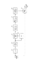
図2は、動きベクトル検出部14の概略構成を示すブロック図である。図18と同一符号は同一構成要素を示しており、重複する説明は省略する。
FIG. 2 is a block diagram illustrating a schematic configuration of the motion
図2においては、ベクトル検出領域単位の動きベクトルを検出する動きベクトル検出回路106の後段に、動きベクトル分類回路30と動きベクトル制御回路31が備えられている点が、図18と相違している。動きベクトル分類回路30の動作について以下に説明する。
2 is different from FIG. 18 in that a motion
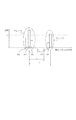
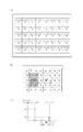
図3(A)は、撮影した現フィールドの画面上に、動きベクトル検出のためのベクトル検出領域を示した一例を示す図である。図3(B)は、直前のフィールドとの差により得られた動きベクトルを示す図である。また、図3(C)は、全ベクトル検出領域の動きベクトルのX方向(画面横方向)、Y方向(画面縦方向)のそれぞれの大きさの頻度を示すヒストグラム(度数分布)である。 FIG. 3A is a diagram showing an example of a vector detection area for detecting a motion vector on the screen of the captured current field. FIG. 3B is a diagram showing a motion vector obtained by the difference from the immediately preceding field. FIG. 3C is a histogram (frequency distribution) showing the frequency of the magnitudes of the motion vectors in all vector detection regions in the X direction (screen horizontal direction) and Y direction (screen vertical direction).
動きベクトル分類回路30では、まずこのヒストグラムデータの作成を行う。より具体的には、度数分布の横軸を動きベクトルの大きさとし、所定の大きさ(範囲)ごとに区切って階級を設定する。そして、検出された各ベクトル検出領域の動きベクトルを、その大きさにより何れの階級に属するかを判断して、それぞれの度数としてプロットする。図3(B)の例によれば、各ベクトル検出領域の動きベクトルとして、トータル40個の動きベクトルが検出されるが、この40の度数を属する階級に振り分けてプロットすることで各階級の度数(頻度)を得ることができる。なお、それぞれ範囲を持つ階級の階級値としては、その階級の上限値と下限値の中間値を用いればよい。
The motion
図4(A)〜(C)は撮影した現フィールドにおける動きベクトルの検出の例を示す図である。図4(A)に示すように時刻t1時に画面内に移動している被写体が存在しているとする。この被写体が移動している場合、前フィールドと現フィールドの差異を取った移動被写体の領域における動きベクトルは、図4(B)に示すようにその他の領域とは異なる。このときX方向の大きさの頻度を表すヒストグラムは、図4(C)に示すように、グループ1とグループ2の2つのピークが存在する形となり、グループ化できる。グループ2は移動被写体の領域の動きベクトルであり、グループ1はその他の領域の動きベクトルであることが、図4(A)との関係で理解できる。ただし、この段階では、分離され得る2つのグループが検出できただけである。どちらのグループが手ぶれのみの動きベクトルを表すグループであるか、手ぶれに被写体の動きが重畳されたグループであるかは、図4(C)のヒストグラムからは分からない。この判断については後述する。
4A to 4C are diagrams showing an example of motion vector detection in the captured current field. As shown in FIG. 4A, it is assumed that there is a moving object in the screen at time t1. When this subject is moving, the motion vector in the region of the moving subject that takes the difference between the previous field and the current field is different from the other regions as shown in FIG. At this time, the histogram representing the frequency of the magnitude in the X direction has two peaks of group 1 and
図5は、撮影した現フィールドの画面上でのベクトル検出領域におけるX方向の大きさの頻度を表したヒストグラムの一例である。まず、検出された動きベクトルをグループに分類する方法について説明する。図5の度数分布上のプロットに対し、プロット503、505のような極値(ピーク)を探索する。ただし、この極値は予め定められた度数pを超えるものである事とする。そして、極値が複数見つかった場合、それらの階級間の距離が予め定められたcを超えるものであるかを判断する。超えているものであれば、それらは互いに別グループと判定し、超えていなければ同一グループであると判定する。このようにして定められたグループは、その中で最も大きな度数を持つ階級をそのグループの代表階級とし、その階級値をそのグループの代表する代表階級値とする。なお、階級間距離cは、動きベクトル検出誤差よりも大きな値に設定される。
FIG. 5 is an example of a histogram representing the frequency of the magnitude in the X direction in the vector detection area on the screen of the captured current field. First, a method for classifying detected motion vectors into groups will be described. With respect to the plot on the frequency distribution of FIG. 5, extreme values (peaks) such as
図5の場合、極値はプロット503とプロット505であり、これらは度数pを超えるものである。そして、これらの階級間の距離はdであり、これはcより大きいので、別グループであると判定できる。一方度数pを超えるものの、極値であるプロット503に隣接するプロット502は、階級間の距離がcを超えるものではないので、極値503のグループと同一グループであると判断できる。そして、これらに隣接し、度数pを超えないプロット501も、極値503のグループと同一グループであると判断できる。同様に、極値505に隣接するプロット504は、極値505と同一グループであると判断できる。このようにして、各ベクトル検出領域ごとに検出された動きベクトルは、1つ以上のグループに分類され、グループには代表する代表階級値、すなわちそのグループとしての代表動きベクトルを求めることができる。なお、このグループ領域ごとに分ける領域分類の処理は、動きベクトル分類回路30で行われる。
In the case of FIG. 5, the extreme values are
次に、図6と図7に示すフローチャートを参照して動きベクトル制御回路31の動作について説明する。図7のステップS10において動きベクトル制御回路31は、動きベクトル分類回路30が現フィールドにおいて複数個の動きベクトルのグループを検出したか否かを判定する。検出された動きベクトルのグループが1つである場合は、ステップS11に進む。また、検出された動きベクトルのグループが複数個存在する場合は、ステップS12に進む。
Next, the operation of the motion
ステップS11においてはベクトル決定を行う。ステップS10で検出された動きベクトルのグループが1つであると判定されたので、当該グループの代表動きベクトルを画面全体(画像データ全体)の動きベクトルとして決定する。 In step S11, vector determination is performed. Since it is determined that there is one group of motion vectors detected in step S10, the representative motion vector of the group is determined as the motion vector of the entire screen (entire image data).
ステップS12において、ステップS10で検出された動きベクトルのグループが複数あると判定されたので、それぞれのグループに属するベクトル検出領域の画面内における重心座標とベクトル検出領域のばらつき度合いを示す値を算出する。 In step S12, since it is determined that there are a plurality of groups of motion vectors detected in step S10, a value indicating the barycentric coordinates in the screen of the vector detection area belonging to each group and the degree of variation of the vector detection area is calculated. .
ここで、ステップS12の処理について図6を用いて説明する。なお、本説明においては、動きベクトルのグループが複数設定されている、図4(A)〜(C)の状態を例に用いる。 Here, the process of step S12 will be described with reference to FIG. In this description, the states of FIGS. 4A to 4C in which a plurality of motion vector groups are set are used as an example.
まず図6(A)に示すように、各ベクトル検出領域の画面内における座標を定義する。 First, as shown in FIG. 6A, the coordinates in the screen of each vector detection area are defined.
いま、図4(C)におけるグループ1に属するベクトル検出領域の重心座標をG01(GX01,GY01)、図4(C)におけるグループ1に属するベクトル検出領域のばらつき度合いを示す値をZ01と定義する。一方、図4(C)におけるグループ2に属するベクトル検出領域の重心座標をG02(GX02,GY02)、図4(C)におけるグループ2に属するベクトル検出領域のばらつき度合いを示す値をZ02と定義する。
Now, centroid coordinates of the vector detection region belonging to group 1 in FIG. 4C are defined as G01 (GX01, GY01), and a value indicating the degree of variation of the vector detection region belonging to group 1 in FIG. 4C is defined as Z01. . On the other hand, the gravity center coordinates of the vector detection region belonging to
ここで、グループ2に属する各ベクトル検出領域の座標は図6(A)に示す座標において、以下の6個となる。
(X1,Y1),(X1,Y2),(X1,Y3),(X2,Y1),(X2,Y2),(X2,Y3)
このとき、G02=(GX02,GY02)、及びZ02を求める計算式を(式1)、(式2)、(式3)に示す。グループ1の重心座標G01=(GX01,GY01)、及びベクトル検出領域のばらつき度合いを示す値Z01についても、同様の方法で求めることができる。
GX02=(X1+X1+X1+X2+X2+X2)/6 (式1)
GY02=(Y1+Y2+Y3+Y1+Y2+Y3)/6 (式2)
Z02=[{(X1−GX02)2+(Y1−GY02)2}+{(X1−GX02)2+(Y2−GY02)2}+
{(X1−GX02)2+(Y3−GY02)2}+{(X2−GX02)2+(Y1−GY02)2}+
{(X2−GX02)2+(Y2−GY02)2}+{(X2−GX02)2+(Y3−GY02)2}]/6 (式3)
図6(B)に、図4(C)におけるグループ1及びグループ2の画面内における重心座標の位置を示す。また、図6(C)に図4(C)のグループ1及びグループ2の代表動きベクトルの大きさとベクトル検出領域のばらつき度合いを示す値の大きさの関係を表すグラフを示す。 図7に示すフローチャートに戻り、次にステップS13において、動きベクトル制御回路31は前フィールドで複数個の動きベクトルのグループが検出されたかどうかの判定を行う。前フィールドで複数個の動きベクトルのグループが検出されていない場合は、ステップS14に進み、前フィールドで複数個の動きベクトルのグループが検出されている場合は、ステップS15に進む。
Here, the coordinates of each vector detection region belonging to
(X1, Y1), (X1, Y2), (X1, Y3), (X2, Y1), (X2, Y2), (X2, Y3)
At this time, equations for obtaining G02 = (GX02, GY02) and Z02 are shown in (Expression 1), (Expression 2), and (Expression 3). The center-of-gravity coordinates G01 = (GX01, GY01) of the group 1 and the value Z01 indicating the degree of variation of the vector detection area can also be obtained by the same method.
GX02 = (X1 + X1 + X1 + X2 + X2 + X2) / 6 (Formula 1)
GY02 = (Y1 + Y2 + Y3 + Y1 + Y2 + Y3) / 6 (Formula 2)
Z02 = [{(X1-GX02 ) 2 + (Y1-GY02) 2} + {(X1-GX02) 2 + (Y2-GY02) 2} +
{(X1-GX02) 2 + (Y3-GY02) 2} + {(X2-GX02) 2 + (Y1-GY02) 2} +
{(X2-GX02) 2 + (Y2-GY02) 2} + {(X2-GX02) 2 + (Y3-GY02) 2}] / 6 ( Equation 3)
FIG. 6B shows the position of the barycentric coordinates in the screen of group 1 and
ステップS14において、動きベクトル制御回路31は1つのグループを基準のグループとして決定する。ステップS14に進んだ場合、ステップS13にて前フィールドで複数個の動きベクトルのグループが検出されていない。よって、画面上に全フィールドでは存在しなかった移動物が入ってきたか、静止していた移動物が動きだした可能性が高い。
In step S14, the motion
本実施例においては、現フィールドでの上記複数個の動きベクトルのグループのうち、ステップS12で求めたベクトル検出領域のばらつき度合いを示す値が大きい方のグループを、移動被写体が存在しないグループつまり背景のグループと判断する。そして、当該グループの代表動きベクトルを画面全体(画像データ全体)の動きベクトルとして決定する。 In the present embodiment, among the plurality of motion vector groups in the current field, a group having a larger value indicating the degree of variation of the vector detection area obtained in step S12 is selected as a group having no moving subject, that is, a background. Judged as a group. Then, the representative motion vector of the group is determined as the motion vector of the entire screen (entire image data).
本実施例においてベクトル検出領域のばらつき度合いを示す値が大きい方のグループを決定する理由は、ほとんどの撮影シーンにおいて、被写体が存在する領域よりも、背景の領域の方が広いためである。また被写体を中心に撮影することが多いため、被写体の大きさがある程度大きい場合においても、ベクトル検出領域のばらつき度合いを示す値は背景の領域の方が大きくなることも理由の一つである。 The reason why the group having the larger value indicating the degree of variation of the vector detection area in this embodiment is determined is that the background area is wider than the area where the subject exists in most shooting scenes. One of the reasons is that the value indicating the degree of variation in the vector detection area is larger in the background area even when the subject is often photographed in the center, even when the size of the object is somewhat large.
現フィールドが図6(B)に示す状態であるとき、グループ1のベクトル検出領域のばらつき度合いを示す値をZ01、グループ2のベクトル検出領域のばらつき度合いを示す値をZ02とする。また、動きベクトルの大きさとベクトル検出領域のばらつき度合いを示す値の大きさの関係を図6(C)に示す。いま、図6(C)の状態においては、Z01>Z02であるので、ベクトル検出領域のばらつき度合いを示す値が大きい方のグループであるグループ1の代表動きベクトルが、画面全体(画像データ全体)の動きベクトルとして決定される。
When the current field is in the state shown in FIG. 6B, a value indicating the degree of variation in the vector detection area of group 1 is Z01, and a value indicating the degree of variation in the vector detection area of
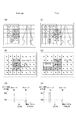
ステップS15においては、動きベクトル制御回路31は移動被写体識別処理を行う。ステップS15に進んだ場合、ステップS13で前フィールドで複数個の動きベクトルのグループが検出されているので、画面上の移動物が移動しているということである。ステップS15の移動被写体識別処理の1つ目の方法について、図8に示す画面の状態図と図9に示すフローチャートを用いて説明する。
In step S15, the motion
ステップS20においては、前フィールドで画面全体の動きベクトルとして決定されたグループ領域と、現フィールドで検出された複数の動きベクトルのグループ領域同士を比較し、対応するグループであるかの判定を行う。具体的には、前フィールドで画面全体の動きベクトルとして決定されたグループの重心座標と、現フィールドで検出された複数の動きベクトルの各グループの重心座標との距離の差分の演算を行う。 In step S20, the group area determined as the motion vector of the entire screen in the previous field is compared with the group areas of a plurality of motion vectors detected in the current field, and it is determined whether the group is a corresponding group. Specifically, the difference between the centroid coordinates of the group determined as the motion vector of the entire screen in the previous field and the centroid coordinates of each group of the plurality of motion vectors detected in the current field is calculated.
ステップS21においては、ステップS20で演算した重心座標同士の距離の差分が最も小さいグループの代表動きベクトルを画面全体の動きベクトルとして決定し、前フィールドで決定されたグループとステップS21にて決定されたグループが同じグループであるとする。以下、ステップS20及びステップS21の処理について詳細に説明を行う。 In step S21, the representative motion vector of the group having the smallest difference in the distance between the barycentric coordinates calculated in step S20 is determined as the motion vector of the entire screen, and the group determined in the previous field is determined in step S21. Assume that the groups are the same group. Hereinafter, the process of step S20 and step S21 will be described in detail.
本実施例においては、前フィールド(時刻t2−Δt)の画面が図8(A)に示す状態であり、Δt秒後の現フィールド(時刻t2)の画面が図8(D)に示す状態であったとする。また、前フィールドの動きベクトルの各グループの重心座標は図8(B)に示す状態であり、現フィールドの動きベクトルの各グループの重心座標は図8(E)に示す状態であるとする。また、前フィールドの動きベクトルの各グループの代表動きベクトルの大きさとばらつき度合いを示す値の関係は図8(C)に示す状態であるとする。また、現フィールドの動きベクトルの各グループの代表動きベクトルの大きさばらつき度合いを示す値の関係は図8(F)に示す状態であるとする。 In this embodiment, the screen of the previous field (time t2−Δt) is in the state shown in FIG. 8A, and the screen of the current field (time t2) after Δt seconds is in the state shown in FIG. Suppose there was. Further, the center-of-gravity coordinates of each group of motion vectors in the previous field are in the state shown in FIG. 8B, and the center-of-gravity coordinates in each group of motion vectors in the current field are in the state shown in FIG. Further, it is assumed that the relationship between the magnitude of the representative motion vector of each group of the motion vectors of the previous field and the value indicating the degree of variation is in the state shown in FIG. Further, it is assumed that the relationship between the values indicating the degree of variation in the magnitude of the representative motion vector of each group of the motion vectors in the current field is as shown in FIG.
またステップS14の処理において、ばらつき度合いを示す値が大きい方のグループである、図8(B)のグループ11が前フィールドで画面全体の動きベクトルとして決定されているものとする。 In step S14, it is assumed that the group 11 in FIG. 8B, which is the group with the larger value indicating the degree of variation, is determined as the motion vector for the entire screen in the previous field.
ステップS20における前フィールドで代表動きベクトルとして決定されたグループの重心座標と、現フィールドで検出された複数の動きベクトルの各グループの重心座標との距離の差分の演算は、以下のように行う。前フィールドで検出されたグループ11の重心座標G11=(GX11,GY11)と、現フィールドで検出されたグループ21の重心座標G21=(GX21,GY21)との距離の差分をΔG[21]とする。また、グループ11の重心座標G11=(GX11,GY11)と、現フィールドで検出されたグループ22の重心座標G22=(GX22,GY22)との距離の差分をΔG[22]とする。ΔG[21]とΔG[22]を求める計算式を(式4)、(式5)に示す。
ΔG[21]=|G11−G21|={(GX11−GX21)2+(GY11−GY21)2}1/2 (式4)
ΔG[22]=|G11−G22|={(GX11−GX22)2+(GY11−GY22)2}1/2 (式5)
NTSC方式においてはフィールド間の期間が1/60秒という短い時間であり、動きベクトルの各グループの重心座標が前フィールドと現フィールドで大きく変わる可能性は低い。よって、現フィールドにおける複数のグループのうち、前フィールドで決定された移動被写体が存在しないグループの重心座標と、重心座標の距離が近い方のグループが、現フィールドにおいて移動被写体が存在しない可能性が高い。よって、前フィールドで画面全体の動きベクトルとして決定されたグループの重心座標と、現フィールドで検出された複数の動きベクトルのグループの重心座標との距離の差分を演算したときに、差分が最も小さいグループを画面全体の動きベクトルとして決定する。こうすることで、移動被写体の存在しないベクトル検出領域のグループをより確実に決定することが可能となる。
The calculation of the difference in distance between the barycentric coordinates of the group determined as the representative motion vector in the previous field in step S20 and the barycentric coordinates of each group of the plurality of motion vectors detected in the current field is performed as follows. The difference in distance between the center of gravity coordinates G11 = (GX11, GY11) of the group 11 detected in the previous field and the center of gravity coordinates G21 = (GX21, GY21) of the
ΔG [21] = | G11−G21 | = {(GX11−GX21) 2 + (GY11−GY21) 2 } 1/2 (Formula 4)
ΔG [22] = | G11−G22 | = {(GX11−GX22) 2 + (GY11−GY22) 2 } 1/2 (Formula 5)
In the NTSC system, the period between fields is a short time of 1/60 seconds, and it is unlikely that the center-of-gravity coordinates of each group of motion vectors greatly change between the previous field and the current field. Therefore, among the plurality of groups in the current field, there is a possibility that there is no moving subject in the current field in the group where the distance between the center of gravity coordinates of the group where the moving subject determined in the previous field does not exist and the center of gravity coordinates are closer. high. Therefore, when the difference between the center of gravity coordinates of the group determined as the motion vector of the entire screen in the previous field and the center of gravity coordinates of the plurality of motion vector groups detected in the current field is calculated, the difference is the smallest. A group is determined as a motion vector for the entire screen. By doing so, it becomes possible to more reliably determine a group of vector detection areas in which no moving subject exists.
ここで、ステップS21において、図8(B)と図8(E)に示すようにΔG[21]<ΔG[22]である。よってグループ21が現フィールドにおいて決定されるグループとなり、グループ21とグループ11が前フィールドで決定された移動被写体が存在しないグループと判断される。
Here, in step S21, ΔG [21] <ΔG [22] as shown in FIGS. 8B and 8E. Therefore, the
なお、ステップS20及びS21の処理において、以下の他の方法でも同様の効果が得られる。前フィールドで画面全体の動きベクトルとして決定されなかったグループの重心座標と、現フィールドで検出された複数の動きベクトルの各グループの重心座標との差分が最も小さいグループを画面全体の動きベクトルの決定対象から除外する。そして残ったグループの代表動きベクトルを画面全体の動きベクトルとして決定するようにしても、同様の効果が得られる。 Note that, in the processes of steps S20 and S21, the same effect can be obtained by the following other methods. Determine the motion vector of the entire screen that has the smallest difference between the centroid coordinates of the group that was not determined as the motion vector of the entire screen in the previous field and the centroid coordinates of each group of multiple motion vectors detected in the current field. Exclude from the target. The same effect can be obtained even if the remaining group representative motion vectors are determined as the motion vectors of the entire screen.
本実施例における動きベクトル検出装置を組み込んだ撮像装置としてのビデオ又はカメラを使用して、移動被写体が存在しないと判断された方のグループに手ぶれ補正処理を行うことで、移動被写体に画面が引っ張られる現象を防止することが可能となる。 Using a video or camera as an imaging device incorporating the motion vector detection device in the present embodiment, the screen is pulled to the moving subject by performing a camera shake correction process on the group that is determined to have no moving subject. Can be prevented.
(実施例2)
ステップS15の移動被写体識別処理の2つ目の方法について、図8に示す画面の状態図と図10に示すフローチャートを用いて説明する。
(Example 2)
The second method of the moving subject identification process in step S15 will be described with reference to the screen state diagram shown in FIG. 8 and the flowchart shown in FIG.
ステップS30において、前フィールドで画面全体の動きベクトルとして決定されたばらつき度合いを示す値と、現フィールドで検出された複数の動きベクトルのばらつき度合いを示す値同士を比較し、対応するグループであるかの判定を行う。具体的には、前フィールドで画面全体の動きベクトルとして決定されたグループのベクトル検出領域のばらつき度合いを示す値と、現フィールドで検出された複数の動きベクトルの各グループのベクトル検出領域のばらつき度合いを示す値同士を比較する。ばらつき度合いを示す値同士の比較は、本実施例では、ばらつきを示す値同士の差分の演算を行う。そしてステップS31において、上記差分が最も小さいグループの代表動きベクトルを画面全体の動きベクトルとして決定する。 In step S30, the value indicating the degree of variation determined as the motion vector of the entire screen in the previous field is compared with the value indicating the degree of variation of the plurality of motion vectors detected in the current field, and is the corresponding group? Judgment is made. Specifically, the value indicating the degree of variation of the vector detection area of the group determined as the motion vector of the entire screen in the previous field, and the degree of variation of the vector detection area of each group of the plurality of motion vectors detected in the current field The values indicating are compared. In the present embodiment, the difference between the values indicating the degree of variation is calculated by calculating the difference between the values indicating the variation. In step S31, the representative motion vector of the group having the smallest difference is determined as the motion vector of the entire screen.
以下、ステップS30及びステップS31の処理について詳細に説明を行うが、本実施例において、図8の状態は実施例1と同様とする。また、ステップS14の処理においてばらつき度合いを示す値が大きい方のグループである、図8(B)のグループ1が前フィールドで画面全体の動きベクトルとして決定されているものとする。 Hereinafter, although the process of step S30 and step S31 is demonstrated in detail, in the present Example, the state of FIG. In addition, it is assumed that group 1 in FIG. 8B, which is a group with a larger value indicating the degree of variation in the process of step S14, is determined as a motion vector for the entire screen in the previous field.
ステップS30では、グループ11のベクトル検出領域のばらつき度合いを示す値Z11と、現フィールドで検出されたグループ21のベクトル検出領域のばらつき度合いを示す値Z21との差分をΔZ[21]とする。また、グループ11のベクトル検出領域のばらつき度合いを示す値Z11と、現フィールドで検出されたグループ22のベクトル検出領域のばらつき度合いを示す値Z22との差分をΔZ[22]とする。ΔZ[21]とΔZ[22]を求める計算式を(式6)、(式7)に示す。
ΔZ[1]=|Z21−Z11| (式6)
ΔZ[2]=|Z22−Z11| (式7)
NTSC方式においてはフィールド間の期間が1/60秒という短い時間であり、現フィールドと1つ前のフィールドでは、ばらつき度合いを示す値が前フィールドと現フィールドで大きく変わる可能性は低い。よって、現フィールドにおける複数のグループのうち、前フィールドで決定された移動被写体が存在しないグループと、ばらつき度合いを示す値が近い方のグループが、現フィールドにおいて移動被写体が存在しない可能性が高い。また、前フィールドで画面全体の動きベクトルとして決定されたグループのばらつき度合いを示す値と、現フィールドで検出された複数の動きベクトルのグループのばらつき度合いを示す値との差分を演算する。そのときに、差分の最も小さいグループを画面全体の動きベクトルとすれば、移動被写体の存在しないベクトル検出領域をより確実に決定することが可能となる。
In step S30, the difference between the value Z11 indicating the degree of variation of the vector detection area of the group 11 and the value Z21 indicating the degree of variation of the vector detection area of the
ΔZ [1] = | Z21−Z11 | (Formula 6)
ΔZ [2] = | Z22−Z11 | (Formula 7)
In the NTSC system, the period between fields is as short as 1/60 seconds, and it is unlikely that the value indicating the degree of variation between the current field and the previous field will change significantly between the previous field and the current field. Therefore, among the plurality of groups in the current field, there is a high possibility that the group in which the moving subject determined in the previous field does not exist and the group having a closer value indicating the degree of variation do not have the moving subject in the current field. Further, the difference between the value indicating the degree of variation of the group determined as the motion vector of the entire screen in the previous field and the value indicating the degree of variation of the group of the plurality of motion vectors detected in the current field is calculated. At that time, if the group having the smallest difference is used as the motion vector for the entire screen, it is possible to more reliably determine the vector detection area where no moving subject exists.
ここで、ステップS31において、図8(B)と図8(E)に示すようにΔZ[21]<ΔZ[22]である。よってグループ21が現フィールドにおいて決定されるグループとなり、グループ21とグループ11が前フィールドで決定された移動被写体が存在しないグループと判断される。
Here, in step S31, ΔZ [21] <ΔZ [22] as shown in FIGS. 8B and 8E. Therefore, the
なお、ステップS30及びS31の処理においては、前フィールドで画面全体の動きベクトルとして決定されなかったグループのばらつき度合いを示す値と、現フィールドで検出された各グループのばらつき度合いを示す値との差分が最も小さいグループを求めてもよい。そして、差分が最も小さかったグループを画面全体の動きベクトルの決定対象から除外し、残ったグループの代表動きベクトルを画面全体の動きベクトルとして決定しても同様の効果が得られる。 In the processes of steps S30 and S31, the difference between the value indicating the degree of variation of the group that has not been determined as the motion vector of the entire screen in the previous field and the value indicating the degree of variation of each group detected in the current field. The group with the smallest may be obtained. The same effect can be obtained by excluding the group having the smallest difference from the determination target of the motion vector for the entire screen and determining the representative motion vector of the remaining group as the motion vector for the entire screen.
これによって、本実施例における動きベクトル検出装置を組み込んだ撮像装置を使用して、移動被写体が存在しないと判断された方のグループに手ぶれ補正処理を行うことで、移動被写体に画面が引っ張られる現象を防止することが可能となる。 As a result, a phenomenon in which the screen is pulled by the moving subject by performing the camera shake correction processing on the group determined to have no moving subject using the imaging device incorporating the motion vector detection device in the present embodiment. Can be prevented.
(実施例3)
ステップS15の移動被写体識別処理の3つ目の方法について、図11に示す画面の状態図と図12に示すフローチャートを用いて説明する。
(Example 3)
The third method of the moving subject identification process in step S15 will be described with reference to the screen state diagram shown in FIG. 11 and the flowchart shown in FIG.
実施例1においては、検出された複数の動きベクトルのグループ化を行った後に、各グループの重心座標を算出することで、前後のフィールドにおけるグループの判別を行ってきた。しかし、図11(D)の場合のように、画面の中央部に被写体が存在する場合は、複数のグループの重心座標が同じになる(もしくは非常に近接する)ことが考えられる。そこで本実施例では、複数のグループの重心座標が同じになる(もしくは非常に近接する)場合を考える。 In the first embodiment, after grouping a plurality of detected motion vectors, the barycentric coordinates of each group are calculated, so that the groups in the preceding and following fields are discriminated. However, as shown in FIG. 11D, when a subject is present at the center of the screen, it is conceivable that the barycentric coordinates of a plurality of groups are the same (or very close). Therefore, in the present embodiment, a case is considered where the barycentric coordinates of a plurality of groups are the same (or very close to each other).
本実施例においては、前フィールド(時刻t3−Δt)の画面が図11(A)に示す状態であり、Δt秒後の現フィールド(時刻t3)の画面が図11(D)に示す状態であったとする。また、前フィールドの動きベクトルの各グループの重心座標は図11(B)に示す状態であり、現フィールドの動きベクトルの各グループの重心座標はK(E)に示す状態であるとする。また、前フィールドの動きベクトルの各グループの、代表動きベクトルの大きさとばらつき度合いを示す値の関係は図11(C)に示す状態であるとする。また、現フィールドの動きベクトルの各グループの、代表動きベクトルの大きさとばらつき度合いを示す値の関係は図11(F)に示す状態であるとする。 In this embodiment, the screen of the previous field (time t3−Δt) is in the state shown in FIG. 11A, and the screen of the current field (time t3) after Δt seconds is in the state shown in FIG. Suppose there was. Further, it is assumed that the center-of-gravity coordinates of each group of motion vectors in the previous field are in the state shown in FIG. 11B, and the center-of-gravity coordinates of each group of motion vectors in the current field are in the state shown in K (E). Further, it is assumed that the relationship between the magnitude of the representative motion vector and the value indicating the degree of variation in each group of motion vectors in the previous field is in the state shown in FIG. Further, it is assumed that the relationship between the magnitude of the representative motion vector and the value indicating the degree of variation in each group of motion vectors in the current field is as shown in FIG.
また、ステップS14の処理において、ばらつき度合いを示す値が大きい方のグループである、図11(B)のグループ31が前フィールドで画面全体の動きベクトルとして決定されているものとする。
In the process of step S14, it is assumed that the
ステップS40において、前フィールドで画面全体の動きベクトルとして決定されたグループ領域と、現フィールドで検出された複数の動きベクトルのグループ領域同士を比較し、対応するグループであるかの判定を行う。具体的には、前フィールドで画面全体の動きベクトルとして決定されたグループの重心座標と、現フィールドで検出された複数の動きベクトルの各グループの重心座標を比較する。また、重心同士の比較は、本実施例では重心座標の距離の差分の演算を行う。これは、ステップS20の処理と同様であるため、説明は省略する。 In step S40, the group area determined as the motion vector of the entire screen in the previous field is compared with the group areas of a plurality of motion vectors detected in the current field, and it is determined whether the group is a corresponding group. Specifically, the barycentric coordinates of the group determined as the motion vector of the entire screen in the previous field are compared with the barycentric coordinates of each group of a plurality of motion vectors detected in the current field. In addition, the comparison between the centroids is performed by calculating the difference between the centroid coordinate distances in this embodiment. Since this is the same as the process of step S20, a description thereof will be omitted.
次に、図11(D)においては移動被写体が画面の中央にいるので、グループ41とグループ42の重心座標G41とG42は一致するか、若しくは近くなる。そのため、前フィールドで画面全体の動きベクトルとして決定されたグループ31の重心座標G31と、グループ41とグループ42の重心座標G41とG42との差分も一致するか、若しくは近い値になる。よって、移動被写体の識別に重心座標の差分のみを用いた場合、重心座標の差分が同じ場合は移動被写体が存在しないグループを識別することが出来ず、また重心座標の差分が近い場合は移動被写体が存在しないグループを誤って識別する危険性がある。
Next, in FIG. 11D, since the moving subject is at the center of the screen, the center-of-gravity coordinates G41 and G42 of the
次にステップS41の処理について説明する。ステップS40で求めた前フィールドにて画面全体の動きベクトルとして決定されたグループの重心座標と、現フィールドで検出された各グループの重心座標との距離の差分同士が所定値(G_DIFF)以上離れているかどうかの判定を行う。 Next, the process of step S41 will be described. The difference between the center of gravity coordinates of the group determined as the motion vector of the entire screen in the previous field obtained in step S40 and the center of gravity coordinates of each group detected in the current field are separated by a predetermined value (G_DIFF) or more. It is determined whether or not.
前述の所定値G_DIFFを、例えば図6(A)における画面上の隣接する動きベクトル検出領域の中心座標同士を結ぶ距離の半分、即ちG_DIFF=(Xi+1−Xi)/2と定義する。本実施例においては、前フィールドで画面全体の動きベクトルとして決定された図11(B)のグループ31の重心座標G31と、図11(E)のグループ41及びグループ42の重心座標G41とG42との距離の差分同士の差がG_DIFF以下であると判定された場合、ステップS42の処理へ移る。すなわち、||G41−G31|−|G42−G31||≦G_DIFFであると判定された場合、ステップS42の処理へ移る。
The aforementioned predetermined value G_DIFF is defined as, for example, half the distance connecting the center coordinates of adjacent motion vector detection areas on the screen in FIG. 6A, that is, G_DIFF = (X i + 1 −X i ) / 2. In this embodiment, the center-of-gravity coordinates G31 of the
ステップS42においては、前フィールドで画面全体の動きベクトルとして決定されたグループのベクトル検出領域のばらつき度合いを示す値と、現フィールドで検出された複数の動きベクトルの各グループのベクトル検出領域のばらつき度合いを示す値同士を比較する。ばらつき度合いを示す値同士の比較は、ばらつきを示す値同士の差分の演算を行う。そしてステップS43において、上記差分が最も小さいグループの代表動きベクトルを画面全体の動きベクトルとして決定する。ステップS42とステップS43の本実施例での処理を以下に記す。 In step S42, the value indicating the degree of variation in the vector detection area of the group determined as the motion vector of the entire screen in the previous field, and the degree of variation in the vector detection area of each group of the plurality of motion vectors detected in the current field The values indicating are compared. Comparison between values indicating the degree of variation is performed by calculating a difference between values indicating variation. In step S43, the representative motion vector of the group having the smallest difference is determined as the motion vector of the entire screen. The processing in this embodiment in step S42 and step S43 will be described below.
ステップS42において、グループ31のベクトル検出領域のばらつき度合いを示す値Z31と、現フィールドで検出されたグループ41のベクトル検出領域のばらつき度合いを示す値Z41との差分をΔZ[41]とする。またグループ31のベクトル検出領域のばらつき度合いを示す値Z31と、現フィールドで検出されたグループ42のベクトル検出領域のばらつき度合いを示す値Z42との差分をΔZ[42]とする。そして、ΔZ[41]とΔZ[42]を求める。ΔZ[41]とΔZ[42]を求める計算式を(式8)、(式9)に示す。
ΔZ[41]=|Z41−Z31| (式8)
ΔZ[42]=|Z42−Z31| (式9)
図11(C)、図11(F)よりΔZ[41]<ΔZ[42]となるため、ステップS43の処理において、グループ41を、グループ31と同じ移動被写体が存在しないグループと判断することが出来る。ステップS43の処理によって、ステップS41の演算結果において、図11(E)に示すように、グループ41とグループ42の重心座標G41とG42が一致する場合であっても、ベクトル検出領域のばらつき度合いを示す値の差分を用いることによって、移動被写体が存在しないグループを判定することが可能となる。
In step S42, the difference between the value Z31 indicating the degree of variation in the vector detection area of the
ΔZ [41] = | Z41−Z31 | (Formula 8)
ΔZ [42] = | Z42−Z31 | (Formula 9)
11C and 11F, ΔZ [41] <ΔZ [42], and therefore, in the process of step S43, it is determined that the
ステップS41において、前フィールドで画面全体の動きベクトルとして決定されたグループの重心座標と、現フィールドで検出された動きベクトルの各グループの重心座標との距離の差分が、所定値G_DIFFより離れている場合は、ステップS44の処理へ移る。 In step S41, the difference in distance between the barycentric coordinates of the group determined as the motion vector of the entire screen in the previous field and the barycentric coordinates of each group of the motion vector detected in the current field is separated from the predetermined value G_DIFF. If so, the process proceeds to step S44.
ステップS44の処理はステップS21と同様であり、前フィールドで画面全体の動きベクトルとして決定されたグループの重心座標と、現フィールドで検出された複数の動きベクトルの各グループの重心座標の距離の差分が、最も小さいグループの代表動きベクトルを現フィールドの画面全体の動きベクトルとして決定する。 The processing in step S44 is the same as in step S21, and the difference between the centroid coordinates of the group determined as the motion vector of the entire screen in the previous field and the centroid coordinates of each group of the plurality of motion vectors detected in the current field. However, the representative motion vector of the smallest group is determined as the motion vector of the entire screen in the current field.
なお、ステップS40からS43の処理においては、以下の方法を用いても同様の効果を得ることができる。すなわち、前フィールドで画面全体の動きベクトルとして決定されなかったグループの重心座標と、現フィールドで検出された複数の動きベクトルの各グループの重心座標との距離の差分を判断する。この重心座標の距離の差分同士が所定値以上離れた値でなければ、前フィールドで画面全体の動きベクトルとして決定されなかったグループのばらつき度合いを示す値と、現フィールドで検出された複数の動きベクトルの各グループのばらつき度合いを示す値との差分が最も小さいグループを画面全体の動きベクトルの決定対象から除外する。そして、残ったグループの代表動きベクトルを画面全体の動きベクトルとして決定するようにしてもよい。 In the processing from step S40 to S43, the same effect can be obtained even if the following method is used. That is, a difference in distance between the barycentric coordinates of the group not determined as the motion vector of the entire screen in the previous field and the barycentric coordinates of each group of the plurality of motion vectors detected in the current field is determined. If the difference between the centroid coordinate distances is not a predetermined value or more, a value indicating the degree of group variation that has not been determined as a motion vector for the entire screen in the previous field and a plurality of motions detected in the current field The group having the smallest difference from the value indicating the degree of variation of each group of vectors is excluded from the motion vector determination target for the entire screen. Then, the remaining group representative motion vectors may be determined as the motion vectors of the entire screen.
これによって、本実施例における動きベクトル検出装置を組み込んだ撮像装置を使用して、移動被写体が存在しないグループと判断された方のグループに手ぶれ補正処理を行うことで、移動被写体に画面が引っ張られる現象を防止することが可能となる。 As a result, by using the imaging device incorporating the motion vector detection device according to the present embodiment and performing the camera shake correction processing on the group that is determined to be a group in which the moving subject does not exist, the screen is pulled by the moving subject. It becomes possible to prevent the phenomenon.
(実施例4)
ステップS15の移動被写体識別処理の4つ目の方法について、図13に示す画面の状態図と図14に示すフローチャートを用いて説明する。
Example 4
The fourth method of the moving subject identification process in step S15 will be described with reference to the screen state diagram shown in FIG. 13 and the flowchart shown in FIG.
実施例2においては、検出された複数の動きベクトルのグループ化を行った後に、各グループのベクトル検出領域の座標のばらつきを示す値を算出することで、前後のフィールドにおけるグループの判別を行ってきた。しかし、図13(D)の場合のように、画面の半分に被写体が存在する場合は、複数の動きベクトルのグループのベクトル検出領域のばらつき度合いを示す値が同じ、もしくは非常に近接することが考えられる。そこで本実施例では、複数の動きベクトルのグループのベクトル検出領域のばらつき度合いを示す値が同じ、もしくは非常に近接する場合を考える。 In the second embodiment, after grouping a plurality of detected motion vectors, a value indicating the variation in the coordinates of the vector detection area of each group is calculated, thereby determining the groups in the preceding and succeeding fields. It was. However, as in the case of FIG. 13D, when the subject is present in half of the screen, the values indicating the degree of variation in the vector detection areas of the plurality of motion vector groups may be the same or very close to each other. Conceivable. Therefore, in the present embodiment, a case is considered where the values indicating the degree of variation in the vector detection areas of a plurality of motion vector groups are the same or very close.
本実施例においては、前フィールド(時刻t4−Δt)の画面が図13(A)に示す状態であり、Δt秒後の現フィールド(時刻t4)の画面が図13(D)に示す状態であったとする。また、前フィールドの動きベクトルの各グループの重心座標は図13(B)に示す状態であり、現フィールドの動きベクトルの各グループの重心座標は図13(E)に示す状態であるとする。また、前フィールドの動きベクトルの各グループの、代表動きベクトルの大きさとベクトル検出領域のばらつき度合いを示す値の関係は図13(C)に示す状態であるとする。また、現フィールドの動きベクトルの各グループの、代表動きベクトルの大きさとばらつき度合いを示す値の関係は図13(F)に示す状態であるとする。また、ステップS14の処理において、ばらつき度合いを示す値が大きい方のグループである、図13(B)のグループ51が前フィールドで代表動きベクトルとして決定されているものとする。 In this embodiment, the screen of the previous field (time t4-Δt) is in the state shown in FIG. 13A, and the screen of the current field (time t4) after Δt seconds is in the state shown in FIG. Suppose there was. Further, the center-of-gravity coordinates of each group of motion vectors in the previous field are in the state shown in FIG. 13B, and the center-of-gravity coordinates in each group of motion vectors in the current field are in the state shown in FIG. Further, it is assumed that the relationship between the magnitude of the representative motion vector and the value indicating the degree of variation of the vector detection area in each group of motion vectors in the previous field is in the state shown in FIG. Further, it is assumed that the relationship between the magnitude of the representative motion vector and the value indicating the degree of variation in each group of motion vectors in the current field is as shown in FIG. In the process of step S14, it is assumed that the group 51 in FIG. 13B, which is the group with the larger value indicating the degree of variation, is determined as the representative motion vector in the previous field.
ステップS50において、前フィールドで画面全体の動きベクトルとして決定されたグループ領域のばらつき度合いを示す値と現フィールドで検出された複数の動きベクトルのグループ領域のばらつき度合いを示す値同士を比較し、対応するグループであるかの判定を行う。具体的には、前フィールドで画面全体の動きベクトルとして決定されたグループのばらつき度合いを示す値と、現フィールドで検出された複数の動きベクトルの各グループのばらつき度合いを示す値同士を比較する。また、ばらつき度合いを示す値同士の比較は、本実施例では、ばらつきを示す値同士の差分の演算を行う。これは、ステップS30の処理と同様であるため、説明は省略する。 In step S50, the value indicating the degree of variation of the group area determined as the motion vector of the entire screen in the previous field is compared with the value indicating the degree of variation of the group area of the plurality of motion vectors detected in the current field, and It is determined whether or not the group is a group to be used. Specifically, the value indicating the degree of variation of the group determined as the motion vector of the entire screen in the previous field is compared with the value indicating the degree of variation of each group of the plurality of motion vectors detected in the current field. Further, the comparison between the values indicating the degree of variation is performed by calculating the difference between the values indicating the variation in this embodiment. Since this is the same as the process of step S30, description is abbreviate | omitted.
次に、現フィールドである図13(D)においては移動被写体が画面の左半分を占めているので、グループ61とグループ62のベクトル検出領域のばらつき度合いを示す値Z61とZ62は一致するか近い値になる。そのため、前フィールドで画面全体の動きベクトルとして決定されたグループ51のベクトル検出領域のばらつき度合いを示す値Z51と、グループ61とグループ62のベクトル検出領域のばらつき度合いを示す値Z61とZ62との差分も一致するか近い値になる。よって、移動被写体の識別にベクトル検出領域のばらつき度合いの差分のみを用いた場合、ベクトル検出領域のばらつき度合いを示す値の差分が同じ場合は移動被写体が存在しないグループを識別することが出来ず、またベクトル検出領域のばらつき度合いを示す値の差分が近い場合は移動被写体が存在しないグループを誤って識別する危険性がある。
Next, in FIG. 13D, which is the current field, since the moving subject occupies the left half of the screen, the values Z61 and Z62 indicating the degree of variation in the vector detection areas of the
そこで、ステップS51にて、ステップS50で求めた前フィールドで画面全体の動きベクトルとして決定されたグループのベクトル検出領域のばらつき度合いを示す値と現フィールドで検出された複数の動きベクトルの各グループのベクトル検出領域のばらつき度合いを示す値との差分同士が、所定値(Z_DIFF)以上離れているかどうかの判定を行う。 Therefore, in step S51, a value indicating the degree of variation in the vector detection area of the group determined as the motion vector of the entire screen in the previous field obtained in step S50 and each group of the plurality of motion vectors detected in the current field. It is determined whether or not the difference from the value indicating the degree of variation of the vector detection area is more than a predetermined value (Z_DIFF).
前述の所定値Z_DIFFを、例えば図6(A)における画面の座標上の隣接する動きベクトル検出領域の中心同士を結ぶ距離の2乗、即ちZ_DIFF=(Xi+1−Xi)2と定義する。本実施例においては、前フィールドで代表動きベクトルとして決定された図11(C)グループの51のばらつき度合いを示す値Z51と、図11(F)のグループ61及びグループ62のばらつき度合いを示す値Z61とZ62との差分同士の差がZ_DIFF以下であると判定された場合ステップS52の処理へ移る。すなわち、||Z61−Z51|−|Z62−Z51||≦Z_DIFFであると判定された場合、ステップS52の処理へ移る。
The aforementioned predetermined value Z_DIFF is defined as, for example, the square of the distance connecting the centers of adjacent motion vector detection areas on the screen coordinates in FIG. 6A, that is, Z_DIFF = (X i + 1 −X i ) 2 . In the present embodiment, the value Z51 indicating the degree of variation in the group 51 in FIG. 11C determined as the representative motion vector in the previous field, and the value indicating the degree of variation in the group 61 and the
ステップS52において、前フィールドで画面全体の動きベクトルとして決定されたグループの重心座標と、現フィールドで検出された複数の動きベクトルの各グループの重心座標同士を比較する。また、重心座標同士の比較は、本実施例では重心座標の距離の差分の演算を行う。そしてステップS53において、上記差分が最も小さいグループの代表動きベクトルを画面全体の動きベクトルとして決定する。ステップS52とステップS53の本実施例での処理を以下に記す。 In step S52, the center-of-gravity coordinates of the group determined as the motion vector of the entire screen in the previous field are compared with the center-of-gravity coordinates of each group of the plurality of motion vectors detected in the current field. Further, the comparison between the centroid coordinates is performed by calculating the difference between the centroid coordinates in the present embodiment. In step S53, the representative motion vector of the group having the smallest difference is determined as the motion vector of the entire screen. The processing in this embodiment in step S52 and step S53 will be described below.
ステップS52において、前フィールドで画面全体の動きベクトルとして決定されたグループ51の重心座標G51と、現フィールドで検出されたグループ61の重心座標G61との差分をΔG[61]とする。また、グループ51の重心座標G51と、現フィールドで検出されたグループ62の重心座標G62との差分をΔG[62]とする。そしてΔG[61]とΔG[62]を求める。ΔG[61]とΔG[62]を求める計算式を(式10)、(式11)に示す。
ΔG[61]=|G61−G51| (式10)
ΔG[62]=|G62−G51| (式11)
図13(B)、図11(E)よりΔG[61]<ΔG[62]となるため、ステップS53の処理において、グループ61を、グループ51と同じ移動被写体が存在しないグループと判断することが出来る。ステップS53の処理によって、ステップS51の演算結果において、図13(F)に示すように、グループ61とグループ62のベクトル検出領域のばらつき度合いを示す値Z61とZ62が一致する場合であっても、重心座標の距離の差分を用いることによって、移動被写体が存在しないグループを判定することが可能となる。
In step S52, the difference between the center-of-gravity coordinates G51 of the group 51 determined as the motion vector of the entire screen in the previous field and the center-of-gravity coordinates G61 of the group 61 detected in the current field is ΔG [61]. Further, a difference between the center-of-gravity coordinates G51 of the group 51 and the center-of-gravity coordinates G62 of the
ΔG [61] = | G61−G51 | (Formula 10)
ΔG [62] = | G62−G51 | (Formula 11)
From FIG. 13B and FIG. 11E, ΔG [61] <ΔG [62], and therefore, in the process of step S53, it is determined that the group 61 is a group in which the same moving subject as the group 51 does not exist. I can do it. Even if the values Z61 and Z62 indicating the degree of variation in the vector detection areas of the group 61 and the
ステップS51において、前フィールドで画面全体の動きベクトルとして決定されたグループのベクトル検出領域のばらつき度合いを示す値と、現フィールドで検出された動きベクトルの各グループのベクトル検出領域のばらつき度合いを示す値との差分が、所定値Z_DIFFより離れている場合は、ステップS54の処理へ移る。 In step S51, a value indicating the degree of variation in the vector detection area of the group determined as the motion vector of the entire screen in the previous field, and a value indicating the degree of variation in the vector detection area of each group of motion vectors detected in the current field Is different from the predetermined value Z_DIFF, the process proceeds to step S54.
ステップS54の処理はステップS31と同様であり、前フィールドで画面全体の動きベクトルとして決定されたグループのベクトル検出領域のばらつき度合いを示す値と、現フィールドで検出された複数の動きベクトルの各グループのベクトル検出領域のばらつき度合いを示す値の差分が、最も小さいグループの代表動きベクトルを現フィールドの画面全体の動きベクトルとして決定する。 The processing in step S54 is the same as in step S31, and a value indicating the degree of variation in the vector detection area of the group determined as the motion vector of the entire screen in the previous field, and each group of the plurality of motion vectors detected in the current field The representative motion vector of the group having the smallest value difference indicating the degree of variation in the vector detection area is determined as the motion vector of the entire screen in the current field.
なお、ステップS50からS53の処理においては、以下の方法を用いても同様の効果を得ることができる。すなわち、前フィールドで画面全体の動きベクトルとして決定されなかったグループのばらつき度合いを示す値と、現フィールドで検出された複数の動きベクトルの各グループのばらつき度合いを示す値との差分を判断する。このばらつき度合いを示す値の差分同士が所定値以上離れた値でなければ、前フィールドで画面全体の動きベクトルとして決定されなかったグループの重心座標と、現フィールドで検出された複数の動きベクトルの各グループの重心座標との距離の差分が最も小さいグループを画面全体の動きベクトルの決定対象から除外する。そして、残ったグループの代表動きベクトルを画面全体の動きベクトルとして決定するようにしてもよい。 In the processing from step S50 to S53, the same effect can be obtained even if the following method is used. That is, the difference between the value indicating the degree of variation of the group not determined as the motion vector of the entire screen in the previous field and the value indicating the degree of variation of each group of the plurality of motion vectors detected in the current field is determined. If the difference between the values indicating the degree of variation is not a predetermined value or more, the barycentric coordinates of the group not determined as the motion vector of the entire screen in the previous field and the plurality of motion vectors detected in the current field The group with the smallest difference in distance from the barycentric coordinates of each group is excluded from the motion vector determination targets for the entire screen. Then, the remaining group representative motion vectors may be determined as the motion vectors of the entire screen.
これによって、本実施例における動きベクトル検出装置を組み込んだ撮像装置を使用して、移動被写体が存在しないグループと判断された方のグループに手ぶれ補正処理を行うことで、移動被写体に画面が引っ張られる現象を防止することが可能となる。 As a result, by using the imaging device incorporating the motion vector detection device according to the present embodiment and performing the camera shake correction processing on the group that is determined to be a group in which the moving subject does not exist, the screen is pulled by the moving subject. It becomes possible to prevent the phenomenon.
(実施例5)
ステップS14の別の実施例として、画面の半分以上を占めるほど大きな移動被写体が存在する場合の実施例を挙げる。
(Example 5)
As another example of step S14, an example in which there is a moving subject that is large enough to occupy more than half of the screen will be described.
ステップS14の処理において、複数グループのうちから1グループを画面全体の動きベクトル(基準グループ)として決定したが、実施例1から4においては、ベクトル検出領域のばらつき度合いを示す値を用いてグループを決定した。しかし、図13のバスの例のように、画面上に大きい移動被写体が存在する場合においては、必ずしもベクトル検出領域のばらつき度合いを示す値が最も大きいグループを背景領域として代表動きベクトルを決定する方が良いとは限らない。 In the process of step S14, one group out of a plurality of groups is determined as the motion vector (reference group) of the entire screen. In the first to fourth embodiments, a group is selected using a value indicating the degree of variation in the vector detection area. Were determined. However, when there is a large moving subject on the screen as in the bus example of FIG. 13, the representative motion vector is not necessarily determined with the group having the largest value indicating the degree of variation in the vector detection area as the background area. Is not always good.
何故なら、画面上に大きい移動被写体が存在する場合は、移動被写体が存在するグループのベクトル検出領域のばらつき度合いを示す値が、移動被写体が存在しないグループのベクトル検出領域のばらつき度合いを示す値よりも、大きくなることがあるからである。そこで本実施例においては、ステップS14の処理で、ベクトル検出領域の数が最も多いグループを画面全体の動きベクトルとして決定されたグループとする。これによって、大きな移動被写体が存在する場合も精度良く、グループの切り分けを行うことが可能になる。 This is because when there is a large moving subject on the screen, the value indicating the degree of variation in the vector detection area of the group where the moving subject exists is greater than the value indicating the degree of variation in the vector detection area of the group where there is no moving subject. This is because it may become large. Therefore, in the present embodiment, the group having the largest number of vector detection areas is determined as the motion vector of the entire screen in the process of step S14. As a result, even when there is a large moving subject, it becomes possible to perform group separation with high accuracy.
なお、ステップS14の基準グループの設定において、移動被写体領域と背景領域の分類に、顔検出機能や色情報、測距による被写体判別などの情報を用いることにより、移動被写体領域と背景領域の判断をより正確に行うことができる。 In the setting of the reference group in step S14, the moving subject region and the background region are determined by using information such as a face detection function, color information, and subject determination by distance measurement for the classification of the moving subject region and the background region. It can be done more accurately.
(その他の実施例)
なお、本発明は、以下の構成でも達成され得る。
(Other examples)
In addition, this invention can be achieved also with the following structures.
実施例1〜5では、ベクトル検出領域の座標の重心あるいはベクトル検出領域の座標のばらつきの度合いを示す値を用いることで、前後のフィールド間での動きベクトルのグループ領域同士を比較した。しかし、本発明を実施するための手段としては、前後のフィールド間での色の相関度合いによって前後のフィールド間での動きベクトルのグループ領域同士を比較しても良い。また、前後のフィールドにおいて、グループ領域に属するベクトル検出領域の数を比較しても良い。 In Examples 1 to 5, group values of motion vectors between the preceding and following fields were compared by using a value indicating the center of gravity of the coordinates of the vector detection region or the degree of variation in the coordinates of the vector detection region. However, as means for carrying out the present invention, the group regions of motion vectors between the preceding and following fields may be compared according to the degree of color correlation between the preceding and following fields. Further, the number of vector detection areas belonging to the group area may be compared in the preceding and following fields.
前述した実施形態の機能を実現するソフトウェアのプログラムコードを記録した記憶媒体を、コンピュータあるいは装置に供給し、そのコンピュータあるいは装置の制御部が記憶媒体に格納されたプログラムコードを読み出し実行することによっても達成され得る。なお、そのコンピュータあるいは装置の制御部とは、例えばシステム制御部やCPU、MPUなどが該当する。 It is also possible to supply a storage medium storing software program codes for realizing the functions of the above-described embodiments to a computer or apparatus, and for the computer or apparatus control unit to read out and execute the program codes stored in the storage medium. Can be achieved. The control unit of the computer or apparatus corresponds to, for example, a system control unit, CPU, MPU, or the like.
この場合、記憶媒体から読み出されたプログラムコード自体が前述した実施形態の機能を実現することになり、前述した実施形態の機能を実現するソフトウェアのプログラムコードを記憶した記憶媒体は本発明を構成することになる。 In this case, the program code itself read from the storage medium realizes the function of the above-described embodiment, and the storage medium storing the program code of the software realizing the function of the above-described embodiment constitutes the present invention. Will do.
プログラムコードを供給するための記憶媒体としては、例えば、フレキシブルディスク、ハードディスク、光ディスク、光磁気ディスク、CD−ROM、CD−R、DVD−ROM、磁気テープ、不揮発性のメモリカード、ROMなどを用いることができる。 As a storage medium for supplying the program code, for example, a flexible disk, hard disk, optical disk, magneto-optical disk, CD-ROM, CD-R, DVD-ROM, magnetic tape, nonvolatile memory card, ROM, or the like is used. be able to.
また、上記実施例1〜5においては、移動被写体が1種類の場合で説明を行ったが、これに限定されるものではない。移動被写体が2種類以上画面内に存在する場合も、同様の考え方を用いることができる。 Moreover, in the said Examples 1-5, although the case where there was one kind of moving subject was demonstrated, it is not limited to this. The same concept can be used when there are two or more moving subjects in the screen.
本画像処理装置を防振機構に組み込むことによって、ビデオ又はカメラによる撮影時に撮影画面内に移動被写体が存在する場合は、移動被写体と背景を動きベクトルを用いることによって切り分けられるため、手ぶれ補正を効率よく行うことが可能である。また、背景に対して手ぶれ補正を働かせることによって防振機能を、被写体に対して手ブレ補正を働かせれば被写体ブレの防止だけでなく追尾機能を働かせることできる。ビデオ又はカメラは家庭用や業務用に限定されず、監視カメラや医療用カメラのような特殊な用途のビデオ又はカメラにも応用可能である。 By incorporating this image processing device into the image stabilization mechanism, if there is a moving subject in the shooting screen during video or camera shooting, the moving subject and the background can be separated by using a motion vector. It can be done well. In addition, the image stabilization function can be applied to the background, and the camera shake correction can be applied to the subject to operate the tracking function as well as the subject shake prevention. The video or camera is not limited to home use or business use, and can also be applied to a special purpose video or camera such as a surveillance camera or a medical camera.
11 光学系 11 Optical system
Claims (10)
前記それぞれのベクトル検出領域にて検出される動きベクトルに基づいて、前記それぞれのベクトル検出領域をグループに分類する領域分類手段と、
前記領域分類手段により分類された結果、前記それぞれのベクトル検出領域が複数のグループに分類された場合に、ある画像の当該複数のグループから基準となる1つのグループを決定し、他の画像の複数のグループのうち、前記他の画像の前記複数のグループの重心と前記ある画像の決定された1つのグループの重心との距離の差分が最も小さいグループを、前記ある画像の基準となるグループとして決定する決定手段と、
前記他の画像の前記決定手段によって決定されたグループと前記ある画像の前記決定手段によって決定されたグループとの間のずれを修正するずれ修正手段を有し、
前記決定手段は、他の画像の複数のグループのうち、前記他の画像の前記複数のグループの重心と前記決定手段によって決定された1つのグループの重心との距離の差分が所定より小さい場合には、
他の画像の複数のグループのうち、前記他の画像の前記複数のグループそれぞれのベクトル検出領域のばらつき度合いを示す値と前記ある画像の前記決定手段によって決定された1つのグループに属するベクトル検出領域のばらつき度合いを示す値との差分が最も小さいグループを、前記ある画像の基準となるグループとして決定することを特徴とする画像処理装置。 Detecting means for setting a plurality of vector detection regions in each of a plurality of images and detecting a motion vector in each of the set vector detection regions from the correlation between the images;
Area classification means for classifying the vector detection areas into groups based on motion vectors detected in the vector detection areas;
When the respective vector detection regions are classified into a plurality of groups as a result of the classification by the region classification means, one reference group is determined from the plurality of groups of a certain image, and a plurality of other images are determined. Among these groups, the group having the smallest difference in distance between the center of gravity of the plurality of groups of the other image and the center of gravity of one group determined for the certain image is determined as a group serving as a reference for the certain image. A decision means to
Have a deviation correction means for correcting the misalignment between the group determined by said determining means of the image with the the group determined by said determining means of said other image,
The determination unit is configured such that, when a difference in distance between the center of gravity of the plurality of groups of the other image and the center of gravity of one group determined by the determination unit is smaller than a predetermined value among a plurality of groups of other images. Is
A vector detection region belonging to one group determined by the determination means of the certain image and a value indicating a variation degree of the vector detection region of each of the plurality of groups of the other image among the plurality of groups of the other image An image processing apparatus , wherein a group having a smallest difference from a value indicating a degree of variation is determined as a reference group for the certain image .
前記それぞれのベクトル検出領域にて検出される動きベクトルに基づいて、前記それぞれのベクトル検出領域をグループに分類する領域分類手段と、
前記領域分類手段により分類された結果、前記それぞれのベクトル検出領域が複数のグループに分類された場合に、ある画像の当該複数のグループから基準となる1つのグループを決定し、他の画像の複数のグループのうち、当該他の画像の前記複数のグループのベクトル検出領域のばらつき度合いを示す値と前記ある画像の決定された1つのグループのベクトル検出領域のばらつき度合いを示す値との差分が最も小さいグループを、前記ある画像の基準となるグループとして決定する決定手段と、
前記他の画像の前記決定手段によって決定されたグループと前記ある画像の前記決定手段によって決定されたグループとの間のずれを修正するずれ修正手段を有し、
前記決定手段は、他の画像の複数のグループのうち、前記他の画像のベクトル検出領域のばらつき度合いを示す値と前記決定手段によって決定された前記ある画像1つのグループのベクトル検出領域のばらつき度合いを示す値との差分が所定より小さい場合には、他の画像の複数のグループのうち、前記他の画像の前記複数のグループそれぞれのベクトル検出領域の重心と前記ある画像の前記決定手段によって決定された1つのグループに属するベクトル検出領域の重心との距離の差分が最も小さいグループを、前記ある画像の基準となるグループとして決定することを特徴とする画像処理装置。 Detecting means for setting a plurality of vector detection regions in each of a plurality of images and detecting a motion vector in each of the set vector detection regions from the correlation between the images;
Area classification means for classifying the vector detection areas into groups based on motion vectors detected in the vector detection areas;
When the respective vector detection regions are classified into a plurality of groups as a result of the classification by the region classification means, one reference group is determined from the plurality of groups of a certain image, and a plurality of other images are determined. The difference between the value indicating the degree of variation in the vector detection areas of the plurality of groups in the other image and the value indicating the degree of variation in the vector detection area of the determined group of the certain image is the largest. Determining means for determining a small group as a reference group of the certain image;
Have a deviation correction means for correcting the misalignment between the group determined by said determining means of the image with the the group determined by said determining means of said other image,
The determining means includes a value indicating a degree of variation of the vector detection area of the other image among a plurality of groups of other images and a degree of variation of the vector detection area of the one image group determined by the determining means. When the difference from the value indicating is smaller than a predetermined value, among the plurality of groups of other images, the center of the vector detection area of each of the plurality of groups of the other image is determined by the determining unit of the certain image An image processing apparatus , wherein a group having a smallest difference in distance from the center of gravity of a vector detection region belonging to one group is determined as a reference group for the certain image .
前記それぞれのベクトル検出領域にて検出される動きベクトルに基づいて、前記それぞれのベクトル検出領域をグループに分類する領域分類工程と、
前記領域分類工程により分類された結果、前記それぞれのベクトル検出領域が複数のグループに分類された場合に、ある画像の当該複数のグループから基準となる1つのグループを決定し、他の画像の複数のグループのうち、前記他の画像の前記複数のグループの重心と前記ある画像の決定された1つのグループの重心との距離の差分が最も小さいグループを、前記ある画像の基準となるグループに対応するグループとして決定する決定工程と、
前記他の画像の前記決定工程によって決定されたグループと前記ある画像の前記決定工程によって決定されたグループとの間のずれを修正するずれ修正工程を有し、
前記決定工程では、他の画像の複数のグループのうち、前記他の画像の前記複数のグループの重心と前記決定工程によって決定された1つのグループの重心との距離の差分が所定値より小さい場合には、
他の画像の複数のグループのうち、前記他の画像の前記複数のグループそれぞれのベクトル検出領域のばらつき度合いを示す値と前記ある画像のグループに属するベクトル検出領域のばらつき度合いを示す値との差分が最も小さいグループを、前記ある画像の基準となるグループとして決定することを特徴とする画像処理方法。 A detection step of setting a plurality of vector detection regions in each of a plurality of images and detecting a motion vector in each of the set vector detection regions from the correlation between the images;
An area classification step for classifying the respective vector detection areas into groups based on motion vectors detected in the respective vector detection areas;
When each of the vector detection regions is classified into a plurality of groups as a result of the classification by the region classification step, one group serving as a reference is determined from the plurality of groups of a certain image, and a plurality of other images are determined. The group having the smallest difference in distance between the center of gravity of the plurality of groups of the other image and the center of gravity of one group determined for the certain image among the groups of the corresponding image corresponds to the group serving as a reference for the certain image A decision process to decide as a group to
Have a deviation correction step for correcting the misalignment between the group determined by said determining step of said other of said determining step the certain image and determined group by image,
In the determination step, a difference in distance between the centroids of the plurality of groups of the other image and the centroid of one group determined by the determination step among a plurality of groups of the other images is smaller than a predetermined value. In
The difference between the value indicating the degree of variation of the vector detection area of each of the plurality of groups of the other image and the value indicating the degree of dispersion of the vector detection area belonging to the group of the certain image among the plurality of groups of the other image An image processing method , wherein a group having the smallest value is determined as a group serving as a reference for the certain image .
前記それぞれのベクトル検出領域にて検出される動きベクトルに基づいて、前記それぞれのベクトル検出領域をグループに分類する領域分類工程と、
前記領域分類工程により分類された結果、前記それぞれのベクトル検出領域が複数のグループに分類された場合に、ある画像の当該複数のグループから基準となる1つのグループを決定し、他の画像の複数のグループのうち、当該他の画像の記複数のグループのベクトル検出領域のばらつき度合いを示す値と前記ある画像の決定された1つのグループのベクトル検出領域のばらつき度合いを示す値との差分が最も小さいグループを、前記ある画像の基準となるグループとして決定する決定工程と、
前記他の画像の前記決定工程によって決定されたグループと前記ある画像の前記決定工程によって決定されたグループとの間のずれを修正するずれ修正工程を有し、
前記決定工程は、他の画像の複数のグループのうち、前記他の画像のベクトル検出領域のばらつき度合いを示す値と前記決定工程によって決定された前記ある画像1つのグループのベクトル検出領域のばらつき度合いを示す値との差分が所定値より小さい場合には、他の画像の複数のグループのうち、前記他の画像の前記複数のグループそれぞれのベクトル検出領域の重心と前記ある画像のグループに属するベクトル検出領域の重心が最も小さいグループを、前記ある画像の基準となるグループとして決定することを特徴とする画像処理方法。 A detection step of setting a plurality of vector detection regions in each of a plurality of images and detecting a motion vector in each of the set vector detection regions from the correlation between the images;
An area classification step for classifying the respective vector detection areas into groups based on motion vectors detected in the respective vector detection areas;
When each of the vector detection regions is classified into a plurality of groups as a result of the classification by the region classification step, one group serving as a reference is determined from the plurality of groups of a certain image, and a plurality of other images are determined. The difference between the value indicating the degree of variation in the vector detection areas of the plurality of groups in the other image and the value indicating the degree of variation in the vector detection area of the determined group of the certain image is the largest. A determination step of determining a small group as a reference group for the certain image;
Have a deviation correction step for correcting the misalignment between the group determined by said determining step of said other of said determining step the certain image and determined group by image,
The determining step includes a value indicating a degree of variation of the vector detection region of the other image among a plurality of groups of other images and a degree of variation of the vector detection region of the one image group determined by the determining step. When the difference from the value indicating is smaller than a predetermined value, among the plurality of groups of other images, the centroid of the vector detection area of each of the plurality of groups of the other image and the vector belonging to the group of the certain image An image processing method , wherein a group having the smallest center of gravity of a detection area is determined as a group serving as a reference for the certain image .
Priority Applications (5)
| Application Number | Priority Date | Filing Date | Title |
|---|---|---|---|
| JP2008248070A JP5213613B2 (en) | 2008-09-26 | 2008-09-26 | Image processing apparatus, image processing method, imaging apparatus, and program |
| EP10187781.9A EP2293540B1 (en) | 2008-09-26 | 2009-09-16 | Image processing apparatus and method for detection and correction of camera shake |
| EP09170469A EP2169945B1 (en) | 2008-09-26 | 2009-09-16 | Image processing apparatus and method for detection and correction of camera shake |
| US12/563,770 US8509481B2 (en) | 2008-09-26 | 2009-09-21 | Image processing apparatus, image processing method, imaging apparatus |
| CN2009101760716A CN101686330B (en) | 2008-09-26 | 2009-09-25 | Image processing apparatus, image processing method, imaging apparatus |
Applications Claiming Priority (1)
| Application Number | Priority Date | Filing Date | Title |
|---|---|---|---|
| JP2008248070A JP5213613B2 (en) | 2008-09-26 | 2008-09-26 | Image processing apparatus, image processing method, imaging apparatus, and program |
Publications (3)
| Publication Number | Publication Date |
|---|---|
| JP2010079655A JP2010079655A (en) | 2010-04-08 |
| JP2010079655A5 JP2010079655A5 (en) | 2011-11-10 |
| JP5213613B2 true JP5213613B2 (en) | 2013-06-19 |
Family
ID=41426265
Family Applications (1)
| Application Number | Title | Priority Date | Filing Date |
|---|---|---|---|
| JP2008248070A Expired - Fee Related JP5213613B2 (en) | 2008-09-26 | 2008-09-26 | Image processing apparatus, image processing method, imaging apparatus, and program |
Country Status (4)
| Country | Link |
|---|---|
| US (1) | US8509481B2 (en) |
| EP (2) | EP2169945B1 (en) |
| JP (1) | JP5213613B2 (en) |
| CN (1) | CN101686330B (en) |
Families Citing this family (24)
| Publication number | Priority date | Publication date | Assignee | Title |
|---|---|---|---|---|
| KR20110068635A (en) * | 2009-12-16 | 2011-06-22 | 삼성전자주식회사 | Apparatus for processing digital image and thereof method and a computer-readable storage medium |
| US8896715B2 (en) * | 2010-02-11 | 2014-11-25 | Microsoft Corporation | Generic platform video image stabilization |
| JP5400718B2 (en) * | 2010-07-12 | 2014-01-29 | 株式会社日立国際電気 | Monitoring system and monitoring method |
| JP5759162B2 (en) * | 2010-12-16 | 2015-08-05 | キヤノン株式会社 | Motion vector detection device, motion vector detection method, correction device, and program |
| US20120162449A1 (en) * | 2010-12-23 | 2012-06-28 | Matthias Braun | Digital image stabilization device and method |
| US8891626B1 (en) * | 2011-04-05 | 2014-11-18 | Google Inc. | Center of motion for encoding motion fields |
| JP2012257080A (en) * | 2011-06-09 | 2012-12-27 | Sony Corp | Image processor, image processing method, and program |
| US9094689B2 (en) | 2011-07-01 | 2015-07-28 | Google Technology Holdings LLC | Motion vector prediction design simplification |
| JP5412692B2 (en) * | 2011-10-04 | 2014-02-12 | 株式会社モルフォ | Image processing apparatus, image processing method, image processing program, and recording medium |
| US9185428B2 (en) | 2011-11-04 | 2015-11-10 | Google Technology Holdings LLC | Motion vector scaling for non-uniform motion vector grid |
| US8908767B1 (en) | 2012-02-09 | 2014-12-09 | Google Inc. | Temporal motion vector prediction |
| US9172970B1 (en) | 2012-05-29 | 2015-10-27 | Google Inc. | Inter frame candidate selection for a video encoder |
| US11317101B2 (en) | 2012-06-12 | 2022-04-26 | Google Inc. | Inter frame candidate selection for a video encoder |
| US9503746B2 (en) | 2012-10-08 | 2016-11-22 | Google Inc. | Determine reference motion vectors |
| US9485515B2 (en) | 2013-08-23 | 2016-11-01 | Google Inc. | Video coding using reference motion vectors |
| US9712818B2 (en) * | 2013-01-11 | 2017-07-18 | Sony Corporation | Method for stabilizing a first sequence of digital image frames and image stabilization unit |
| US9313493B1 (en) | 2013-06-27 | 2016-04-12 | Google Inc. | Advanced motion estimation |
| US10354397B2 (en) | 2015-03-11 | 2019-07-16 | Massachusetts Institute Of Technology | Methods and apparatus for modeling deformations of an object |
| JP6577852B2 (en) * | 2015-12-03 | 2019-09-18 | キヤノン株式会社 | Motion vector detection device and control method thereof |
| EP3184251A1 (en) * | 2015-12-22 | 2017-06-28 | HILTI Aktiengesellschaft | Combustion-driven setting tool and method for operating such a setting tool |
| JP6661493B2 (en) * | 2016-08-30 | 2020-03-11 | キヤノン株式会社 | Image blur control device, imaging device, and control method |
| US10380745B2 (en) * | 2016-09-01 | 2019-08-13 | Massachusetts Institute Of Technology | Methods and devices for measuring object motion using camera images |
| JP6922951B2 (en) * | 2019-08-09 | 2021-08-18 | フジテック株式会社 | Image processing device and image processing method |
| US11874415B2 (en) * | 2020-12-22 | 2024-01-16 | International Business Machines Corporation | Earthquake detection and response via distributed visual input |
Family Cites Families (32)
| Publication number | Priority date | Publication date | Assignee | Title |
|---|---|---|---|---|
| JPH06133298A (en) | 1992-10-14 | 1994-05-13 | Canon Inc | Motion vector detector |
| JP2951230B2 (en) * | 1994-09-22 | 1999-09-20 | 三洋電機株式会社 | Method for generating 3D image from 2D image |
| KR100235343B1 (en) * | 1994-12-29 | 1999-12-15 | 전주범 | Apparatus for calculating motion vector in encoder using segmentation method |
| KR0171154B1 (en) * | 1995-04-29 | 1999-03-20 | 배순훈 | Method and apparatus for encoding video signals using feature point based motion prediction |
| JP3657116B2 (en) * | 1997-05-14 | 2005-06-08 | 株式会社日立国際電気 | Object tracking method and object tracking apparatus |
| US6766037B1 (en) * | 1998-10-02 | 2004-07-20 | Canon Kabushiki Kaisha | Segmenting moving objects and determining their motion |
| US6597738B1 (en) * | 1999-02-01 | 2003-07-22 | Hyundai Curitel, Inc. | Motion descriptor generating apparatus by using accumulated motion histogram and a method therefor |
| US6809758B1 (en) * | 1999-12-29 | 2004-10-26 | Eastman Kodak Company | Automated stabilization method for digital image sequences |
| KR100683849B1 (en) * | 2000-06-28 | 2007-02-15 | 삼성전자주식회사 | Decoder having digital image stabilization function and digital image stabilization method |
| US8134613B2 (en) * | 2001-04-10 | 2012-03-13 | Sony Corporation | Image processing apparatus and method, and image pickup apparatus |
| US7646891B2 (en) * | 2002-12-26 | 2010-01-12 | Mitshubishi Denki Kabushiki Kaisha | Image processor |
| US7095786B1 (en) * | 2003-01-11 | 2006-08-22 | Neo Magic Corp. | Object tracking using adaptive block-size matching along object boundary and frame-skipping when object motion is low |
| US7111529B2 (en) * | 2003-07-25 | 2006-09-26 | Pradelski William W | Ratchetable open-ended wrench |
| JP3838243B2 (en) * | 2003-09-04 | 2006-10-25 | ソニー株式会社 | Image processing method, image processing apparatus, and computer program |
| US7457438B2 (en) * | 2003-12-23 | 2008-11-25 | Genesis Microchip Inc. | Robust camera pan vector estimation using iterative center of mass |
| KR101108634B1 (en) * | 2004-01-06 | 2012-01-31 | 소니 주식회사 | Image processing device and image processing method and recording medium |
| US7433497B2 (en) * | 2004-01-23 | 2008-10-07 | Hewlett-Packard Development Company, L.P. | Stabilizing a sequence of image frames |
| US8036494B2 (en) * | 2004-04-15 | 2011-10-11 | Hewlett-Packard Development Company, L.P. | Enhancing image resolution |
| US7649549B2 (en) * | 2004-09-27 | 2010-01-19 | Texas Instruments Incorporated | Motion stabilization in video frames using motion vectors and reliability blocks |
| JP4379918B2 (en) * | 2004-11-29 | 2009-12-09 | 富士フイルム株式会社 | Imaging apparatus and imaging method |
| JP2007142883A (en) * | 2005-11-18 | 2007-06-07 | Canon Inc | Image processing device and image processing method |
| JP4304528B2 (en) * | 2005-12-01 | 2009-07-29 | ソニー株式会社 | Image processing apparatus and image processing method |
| US8116576B2 (en) * | 2006-03-03 | 2012-02-14 | Panasonic Corporation | Image processing method and image processing device for reconstructing a high-resolution picture from a captured low-resolution picture |
| JP4595834B2 (en) * | 2006-03-03 | 2010-12-08 | 日本ビクター株式会社 | Motion vector detection method and apparatus |
| JP2007272731A (en) * | 2006-03-31 | 2007-10-18 | Sony Corp | Image processing apparatus and method, and program |
| JP4961850B2 (en) * | 2006-06-15 | 2012-06-27 | ソニー株式会社 | Motion detection method, motion detection method program, recording medium recording motion detection method program, and motion detection apparatus |
| JP4686663B2 (en) * | 2006-07-10 | 2011-05-25 | 国立大学法人京都大学 | Pedestrian tracking method and pedestrian tracking device |
| US7783118B2 (en) * | 2006-07-13 | 2010-08-24 | Seiko Epson Corporation | Method and apparatus for determining motion in images |
| JP4274233B2 (en) * | 2006-11-30 | 2009-06-03 | ソニー株式会社 | Imaging apparatus, image processing apparatus, image processing method therefor, and program causing computer to execute the method |
| US7956899B2 (en) * | 2007-08-29 | 2011-06-07 | Sanyo Electric Co., Ltd. | Imaging device and image processing apparatus |
| US8063942B2 (en) * | 2007-10-19 | 2011-11-22 | Qualcomm Incorporated | Motion assisted image sensor configuration |
| JP5048542B2 (en) * | 2008-02-07 | 2012-10-17 | オリンパス株式会社 | Image processing apparatus and image processing program |
-
2008
- 2008-09-26 JP JP2008248070A patent/JP5213613B2/en not_active Expired - Fee Related
-
2009
- 2009-09-16 EP EP09170469A patent/EP2169945B1/en not_active Not-in-force
- 2009-09-16 EP EP10187781.9A patent/EP2293540B1/en not_active Not-in-force
- 2009-09-21 US US12/563,770 patent/US8509481B2/en not_active Expired - Fee Related
- 2009-09-25 CN CN2009101760716A patent/CN101686330B/en not_active Expired - Fee Related
Also Published As
| Publication number | Publication date |
|---|---|
| EP2169945A2 (en) | 2010-03-31 |
| JP2010079655A (en) | 2010-04-08 |
| CN101686330B (en) | 2012-02-22 |
| EP2293540A1 (en) | 2011-03-09 |
| US20100079624A1 (en) | 2010-04-01 |
| US8509481B2 (en) | 2013-08-13 |
| EP2169945B1 (en) | 2012-08-08 |
| EP2169945A3 (en) | 2010-04-07 |
| EP2293540B1 (en) | 2013-11-06 |
| CN101686330A (en) | 2010-03-31 |
Similar Documents
| Publication | Publication Date | Title |
|---|---|---|
| JP5213613B2 (en) | Image processing apparatus, image processing method, imaging apparatus, and program | |
| EP1578116B1 (en) | Image processor | |
| JP4876065B2 (en) | Motion vector detection device, motion vector detection method, imaging device, and program | |
| KR101861722B1 (en) | Method of processing video data and image processing circuit | |
| KR100252080B1 (en) | Apparatus for stabilizing video signals through revising the motion of the video signals using bit plane matching and a stabilizing method therefor | |
| JP2010118862A (en) | Image processor, imaging apparatus and image processing method | |
| US9865064B2 (en) | Image processing apparatus, image processing method, and storage medium | |
| JP2002305683A (en) | Image pickup device and recording medium for recording image pickup program | |
| JP7223079B2 (en) | IMAGE PROCESSING APPARATUS, CONTROL METHOD THEREOF, AND IMAGING APPARATUS | |
| EP2219366A1 (en) | Image capturing device, image capturing method, and image capturing program | |
| JP2010114752A (en) | Device and method of imaging and program | |
| JPH08251474A (en) | Motion vector detector, motion vector detection method, image shake correction device, image tracking device and image pickup device | |
| WO2007129591A1 (en) | Shielding-object video-image identifying device and method | |
| JP2009260671A (en) | Image processing apparatus and imaging device | |
| JP5300413B2 (en) | Motion vector detection device, motion vector detection method, imaging device, and program | |
| JP2006215655A (en) | Method, apparatus, program and program storage medium for detecting motion vector | |
| JP5539565B2 (en) | Imaging apparatus and subject tracking method | |
| JP2009088884A (en) | Method and device for detecting motion vector in picked-up data | |
| JP5029573B2 (en) | Imaging apparatus and imaging method | |
| JP5759162B2 (en) | Motion vector detection device, motion vector detection method, correction device, and program | |
| JP2014153517A (en) | Image processing device, image processing method, program, and storage medium | |
| US20220198683A1 (en) | Object tracking apparatus and control method thereof using weight map based on motion vectors | |
| JP2008118340A (en) | Motion vector detecting device and video signal processor | |
| JP6274778B2 (en) | Image processing method, image processing apparatus, and computer program | |
| JP2925890B2 (en) | Video camera with image stabilization device |
Legal Events
| Date | Code | Title | Description |
|---|---|---|---|
| RD04 | Notification of resignation of power of attorney |
Free format text: JAPANESE INTERMEDIATE CODE: A7424 Effective date: 20100201 |
|
| RD01 | Notification of change of attorney |
Free format text: JAPANESE INTERMEDIATE CODE: A7421 Effective date: 20100630 |
|
| A521 | Request for written amendment filed |
Free format text: JAPANESE INTERMEDIATE CODE: A523 Effective date: 20110926 |
|
| A621 | Written request for application examination |
Free format text: JAPANESE INTERMEDIATE CODE: A621 Effective date: 20110926 |
|
| A977 | Report on retrieval |
Free format text: JAPANESE INTERMEDIATE CODE: A971007 Effective date: 20120913 |
|
| A131 | Notification of reasons for refusal |
Free format text: JAPANESE INTERMEDIATE CODE: A131 Effective date: 20120918 |
|
| A521 | Request for written amendment filed |
Free format text: JAPANESE INTERMEDIATE CODE: A523 Effective date: 20121115 |
|
| TRDD | Decision of grant or rejection written | ||
| A01 | Written decision to grant a patent or to grant a registration (utility model) |
Free format text: JAPANESE INTERMEDIATE CODE: A01 Effective date: 20130129 |
|
| A61 | First payment of annual fees (during grant procedure) |
Free format text: JAPANESE INTERMEDIATE CODE: A61 Effective date: 20130226 |
|
| R151 | Written notification of patent or utility model registration |
Ref document number: 5213613 Country of ref document: JP Free format text: JAPANESE INTERMEDIATE CODE: R151 |
|
| FPAY | Renewal fee payment (event date is renewal date of database) |
Free format text: PAYMENT UNTIL: 20160308 Year of fee payment: 3 |
|
| LAPS | Cancellation because of no payment of annual fees |