JP2018024571A - Manufacturing method of glass substrate having pores - Google Patents
Manufacturing method of glass substrate having pores Download PDFInfo
- Publication number
- JP2018024571A JP2018024571A JP2017149004A JP2017149004A JP2018024571A JP 2018024571 A JP2018024571 A JP 2018024571A JP 2017149004 A JP2017149004 A JP 2017149004A JP 2017149004 A JP2017149004 A JP 2017149004A JP 2018024571 A JP2018024571 A JP 2018024571A
- Authority
- JP
- Japan
- Prior art keywords
- glass plate
- hole
- initial
- glass
- dummy
- Prior art date
- Legal status (The legal status is an assumption and is not a legal conclusion. Google has not performed a legal analysis and makes no representation as to the accuracy of the status listed.)
- Withdrawn
Links
Images


Classifications
-
- C—CHEMISTRY; METALLURGY
- C03—GLASS; MINERAL OR SLAG WOOL
- C03B—MANUFACTURE, SHAPING, OR SUPPLEMENTARY PROCESSES
- C03B33/00—Severing cooled glass
- C03B33/08—Severing cooled glass by fusing, i.e. by melting through the glass
- C03B33/082—Severing cooled glass by fusing, i.e. by melting through the glass using a focussed radiation beam, e.g. laser
-
- B—PERFORMING OPERATIONS; TRANSPORTING
- B23—MACHINE TOOLS; METAL-WORKING NOT OTHERWISE PROVIDED FOR
- B23K—SOLDERING OR UNSOLDERING; WELDING; CLADDING OR PLATING BY SOLDERING OR WELDING; CUTTING BY APPLYING HEAT LOCALLY, e.g. FLAME CUTTING; WORKING BY LASER BEAM
- B23K26/00—Working by laser beam, e.g. welding, cutting or boring
- B23K26/0006—Working by laser beam, e.g. welding, cutting or boring taking account of the properties of the material involved
-
- B—PERFORMING OPERATIONS; TRANSPORTING
- B23—MACHINE TOOLS; METAL-WORKING NOT OTHERWISE PROVIDED FOR
- B23K—SOLDERING OR UNSOLDERING; WELDING; CLADDING OR PLATING BY SOLDERING OR WELDING; CUTTING BY APPLYING HEAT LOCALLY, e.g. FLAME CUTTING; WORKING BY LASER BEAM
- B23K26/00—Working by laser beam, e.g. welding, cutting or boring
- B23K26/352—Working by laser beam, e.g. welding, cutting or boring for surface treatment
- B23K26/355—Texturing
-
- B—PERFORMING OPERATIONS; TRANSPORTING
- B23—MACHINE TOOLS; METAL-WORKING NOT OTHERWISE PROVIDED FOR
- B23K—SOLDERING OR UNSOLDERING; WELDING; CLADDING OR PLATING BY SOLDERING OR WELDING; CUTTING BY APPLYING HEAT LOCALLY, e.g. FLAME CUTTING; WORKING BY LASER BEAM
- B23K26/00—Working by laser beam, e.g. welding, cutting or boring
- B23K26/352—Working by laser beam, e.g. welding, cutting or boring for surface treatment
- B23K26/359—Working by laser beam, e.g. welding, cutting or boring for surface treatment by providing a line or line pattern, e.g. a dotted break initiation line
-
- B—PERFORMING OPERATIONS; TRANSPORTING
- B23—MACHINE TOOLS; METAL-WORKING NOT OTHERWISE PROVIDED FOR
- B23K—SOLDERING OR UNSOLDERING; WELDING; CLADDING OR PLATING BY SOLDERING OR WELDING; CUTTING BY APPLYING HEAT LOCALLY, e.g. FLAME CUTTING; WORKING BY LASER BEAM
- B23K26/00—Working by laser beam, e.g. welding, cutting or boring
- B23K26/36—Removing material
- B23K26/38—Removing material by boring or cutting
- B23K26/382—Removing material by boring or cutting by boring
-
- B—PERFORMING OPERATIONS; TRANSPORTING
- B23—MACHINE TOOLS; METAL-WORKING NOT OTHERWISE PROVIDED FOR
- B23K—SOLDERING OR UNSOLDERING; WELDING; CLADDING OR PLATING BY SOLDERING OR WELDING; CUTTING BY APPLYING HEAT LOCALLY, e.g. FLAME CUTTING; WORKING BY LASER BEAM
- B23K26/00—Working by laser beam, e.g. welding, cutting or boring
- B23K26/36—Removing material
- B23K26/40—Removing material taking account of the properties of the material involved
- B23K26/402—Removing material taking account of the properties of the material involved involving non-metallic material, e.g. isolators
-
- C—CHEMISTRY; METALLURGY
- C03—GLASS; MINERAL OR SLAG WOOL
- C03B—MANUFACTURE, SHAPING, OR SUPPLEMENTARY PROCESSES
- C03B17/00—Forming molten glass by flowing-out, pushing-out, extruding or drawing downwardly or laterally from forming slits or by overflowing over lips
- C03B17/06—Forming glass sheets
- C03B17/064—Forming glass sheets by the overflow downdraw fusion process; Isopipes therefor
-
- C—CHEMISTRY; METALLURGY
- C03—GLASS; MINERAL OR SLAG WOOL
- C03C—CHEMICAL COMPOSITION OF GLASSES, GLAZES OR VITREOUS ENAMELS; SURFACE TREATMENT OF GLASS; SURFACE TREATMENT OF FIBRES OR FILAMENTS MADE FROM GLASS, MINERALS OR SLAGS; JOINING GLASS TO GLASS OR OTHER MATERIALS
- C03C15/00—Surface treatment of glass, not in the form of fibres or filaments, by etching
-
- C—CHEMISTRY; METALLURGY
- C03—GLASS; MINERAL OR SLAG WOOL
- C03C—CHEMICAL COMPOSITION OF GLASSES, GLAZES OR VITREOUS ENAMELS; SURFACE TREATMENT OF GLASS; SURFACE TREATMENT OF FIBRES OR FILAMENTS MADE FROM GLASS, MINERALS OR SLAGS; JOINING GLASS TO GLASS OR OTHER MATERIALS
- C03C23/00—Other surface treatment of glass not in the form of fibres or filaments
- C03C23/0005—Other surface treatment of glass not in the form of fibres or filaments by irradiation
- C03C23/0025—Other surface treatment of glass not in the form of fibres or filaments by irradiation by a laser beam
-
- B—PERFORMING OPERATIONS; TRANSPORTING
- B23—MACHINE TOOLS; METAL-WORKING NOT OTHERWISE PROVIDED FOR
- B23K—SOLDERING OR UNSOLDERING; WELDING; CLADDING OR PLATING BY SOLDERING OR WELDING; CUTTING BY APPLYING HEAT LOCALLY, e.g. FLAME CUTTING; WORKING BY LASER BEAM
- B23K2103/00—Materials to be soldered, welded or cut
- B23K2103/50—Inorganic material, e.g. metals, not provided for in B23K2103/02 – B23K2103/26
- B23K2103/54—Glass
Abstract
Description
本発明は、例えば、貫通孔または非貫通孔などの孔を有するガラス基板の製造方法に関する。 The present invention relates to a method for producing a glass substrate having holes such as through holes or non-through holes.
従来より、レーザ光照射技術を利用して、貫通孔または非貫通孔などの孔を有するガラス基板を製造する技術が知られている。 2. Description of the Related Art Conventionally, a technique for manufacturing a glass substrate having a hole such as a through hole or a non-through hole using a laser beam irradiation technique is known.
例えば、貫通孔を有するガラス基板を製造する場合、通常、
(A)第1および第2の表面を有し、第1の厚さを有するガラス板を準備する工程と、
(B)ガラス板の第1の表面の側からレーザ光を照射して、ガラス板に貫通孔を形成する工程と、
(C)ガラス板を湿式エッチングすることにより、前記貫通孔を所定の寸法に拡張する工程と、
が実施される。
For example, when manufacturing a glass substrate having a through hole,
(A) preparing a glass plate having first and second surfaces and having a first thickness;
(B) irradiating laser light from the first surface side of the glass plate to form a through hole in the glass plate;
(C) expanding the through hole to a predetermined size by wet etching the glass plate;
Is implemented.
ここで、(C)の工程を実施した場合、最終的に得られる貫通孔を所望の範囲の寸法に拡張することはできるものの、同時にガラス基板の厚さも減少してしまう。このため、ガラス基板の最終厚さが所定の範囲から逸脱してしまうという問題が生じ得る。 Here, when the step (C) is performed, although the finally obtained through hole can be expanded to a desired range of dimensions, the thickness of the glass substrate is also reduced at the same time. For this reason, the problem that the final thickness of a glass substrate will deviate from a predetermined range may arise.
また、このような問題を回避するため、(B)の工程で、予め所定の寸法に近い貫通孔を形成しようとすると、ガラス板にクラックが生じる可能性が高くなり、生産の歩留まりが低下してしまう。 Moreover, in order to avoid such a problem, in the step (B), if a through hole close to a predetermined dimension is to be formed in advance, there is a high possibility that a crack will occur in the glass plate, resulting in a decrease in production yield. End up.
本発明は、このような背景に鑑みなされたものであり、本発明では、所望の寸法の孔を有する所望の厚さのガラス基板を、高い歩留まりで製造することが可能な方法を提供することを目的とする。 This invention is made | formed in view of such a background, and this invention provides the method of manufacturing the glass substrate of the desired thickness which has a hole of a desired dimension with a high yield. With the goal.
本発明では、直径φfの孔を有する厚さθfのガラス基板の製造方法であって、
(1)被処理ガラス板の厚さθ1を定める工程と、
(2)相互に対向する第1および第2の表面を有し、前記厚さθ1を有するガラス板を準備する工程と、
(3)前記ガラス板の前記第1の表面の側からレーザ光を照射することにより、前記ガラス板に1または2以上の初期特徴物を形成する工程であって、前記初期特徴物は、前記第1の表面に直径φ1の寸法を有する、工程と、
(4)前記初期特徴物を有するガラス板を湿式エッチングする工程であって、これにより、前記初期特徴物から、前記第1の表面に直径φfを有する孔が形成されるとともに、前記ガラス板の厚さがθ1から、目標値θfに調整される工程と、
を有する製造方法が提供される。
In the present invention, a method for producing a glass substrate with a thickness θ f having a hole with a diameter φ f ,
(1) a step of determining the thickness θ 1 of the glass plate to be treated;
(2) preparing a glass plate having first and second surfaces facing each other and having the thickness θ 1 ;
(3) A step of forming one or more initial features on the glass plate by irradiating laser light from the first surface side of the glass plate, wherein the initial features are Having a dimension of diameter φ 1 on the first surface;
(4) Wet etching the glass plate having the initial feature, whereby a hole having a diameter φ f is formed in the first surface from the initial feature, and the glass plate The thickness of is adjusted from θ 1 to the target value θ f ,
A manufacturing method is provided.
本発明では、所望の寸法の孔を有する所望の厚さのガラス基板を、高い歩留まりで製造することが可能な方法を提供することができる。 In the present invention, it is possible to provide a method capable of manufacturing a glass substrate having a desired thickness having a hole having a desired dimension with a high yield.
以下、図面を参照して、本発明の一実施形態について説明する。 Hereinafter, an embodiment of the present invention will be described with reference to the drawings.
(従来の貫通孔を有するガラス基板の製造方法)
まず、本発明の特徴をより良く理解するため、図1を参照して、従来の貫通孔を有するガラス基板の製造方法について簡単に説明する。
(Conventional method for producing a glass substrate having a through hole)
First, in order to better understand the features of the present invention, a conventional method for manufacturing a glass substrate having a through hole will be briefly described with reference to FIG.
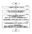
図1には、従来の貫通孔を有するガラス基板の製造方法における各工程の態様を模式的に示す。 In FIG. 1, the aspect of each process in the manufacturing method of the conventional glass substrate which has a through-hole is shown typically.
従来の貫通孔を有するガラス基板の製造方法(以下、「従来方法」という)は、通常、
(A)第1および第2の表面を有し、第1の厚さを有するガラス板を準備する工程(第1の工程)と、
(B)ガラス板の第1の表面の側から、レーザ光を照射して、貫通孔を形成する工程(第2の工程)と、
(C)貫通孔を有するガラス板を湿式エッチングして、貫通孔の寸法を広げる工程(第3の工程)と、
を有する。
A conventional method for producing a glass substrate having a through-hole (hereinafter referred to as “conventional method”)
(A) a step (first step) of preparing a glass plate having first and second surfaces and having a first thickness;
(B) A step of irradiating a laser beam from the first surface side of the glass plate to form a through hole (second step);
(C) wet etching a glass plate having a through hole to widen the dimension of the through hole (third step);
Have
まず、第1の工程では、図1の(a)に示すように、第1の表面12および第2の表面14を有するガラス板10が準備される。ガラス板10は、厚さθaを有する。ガラス板10の厚さθaは、貫通孔を有するガラス基板の最終的な厚さ目標値θfに設定される(従ってθa=θf)。
First, in a 1st process, as shown to (a) of FIG. 1, the
次に、第2の工程では、図1の(b)に示すように、ガラス板10に1または2以上の貫通孔(以降、「初期貫通孔」という)25が形成される。初期貫通孔25は、ガラス板10の第1の表面12の側からレーザ光を照射することにより形成される。初期貫通孔25は、ガラス板10の第1の表面12の側に第1の開口26aを有し、ガラス板10の第2の表面14の側に第2の開口26bを有する。
Next, in the second step, as shown in FIG. 1B, one or more through holes (hereinafter referred to as “initial through holes”) 25 are formed in the
なお、通常の場合、初期貫通孔25は、ガラス板10の第1の表面12から第2の表面14に向かって径が細くなるような、テーパ形状で形成される。すなわち、第1の開口26aの直径>第2の開口26bの直径となる。
In the normal case, the initial through
ただし、ここでは、簡単のため、初期貫通孔25の断面直径は、該初期貫通孔25の延伸方向に沿って一定(φ1)であると仮定する。すなわち、初期貫通孔25の第1の開口26aの直径および第2の開口26bの直径は、いずれもφ1であると仮定する。
However, here, for the sake of simplicity, it is assumed that the cross-sectional diameter of the initial through
ここで、通常、レーザ光による加工のみでは、初期貫通孔25の直径φ1が所定の寸法に満たない場合がしばしば生じる。そこで、通常の場合、第3の工程(湿式エッチング工程)が引き続き実施される。
Here, usually, the diameter φ 1 of the initial through
第3の工程により、ガラス板10が湿式エッチングされ、これにより、初期貫通孔25が所定の寸法にまで広げられる。例えば、図1の(c)に示した例では、ガラス板10の湿式エッチングにより、初期貫通孔25は、貫通孔35に変化する。すなわち、初期貫通孔25の第1の開口26aの寸法は、φ1からφ2に拡張される。
In the third step, the
これにより、所望の寸法を有する貫通孔35を有するガラス基板30を製造することができる。
Thereby, the
なお、このような従来方法において、第3の工程を省略するため、第2の工程において、レーザ加工により、予め所定の寸法を有する貫通孔(貫通孔35)を直接形成することが考えられる。しかしながら、レーザ光照射により、そのような大きな寸法の貫通孔を直接形成した場合、ガラス板10にクラックが生じる可能性が高くなり、生産の歩留まりが低下してしまう。従って、第3の工程を省略することは、生産性の観点から、現実的ではない。このため、従来方法において、第3の工程が省略されることはあまり想定されない。
In such a conventional method, since the third step is omitted, it is conceivable to directly form a through-hole (through-hole 35) having a predetermined dimension in advance by laser processing in the second step. However, when a through hole having such a large dimension is directly formed by laser light irradiation, the possibility of cracking in the
ここで、従来方法では、図1(c)に示すように、第3の工程により、ガラス板10自身もエッチングされ、厚さがθaからθbに減少する。このため、製造後のガラス基板30の厚さθbは、目標値であるθfに満たなくなってしまうという問題が生じる。
Here, in the conventional method, as shown in FIG. 1 (c), the third step, the
なお、これまで、湿式エッチングによるガラス板10の厚さの変化量自体は、あまり大きくはなく、例えば数十μmオーダーであった。このため、これまではこのようなガラス板10の厚さ変化の問題が顕在することは少なかった。
Until now, the amount of change in the thickness of the
しかしながら、貫通孔を有するガラス基板は、例えば半導体素子のガラスインターポーザ等に使用される。この分野では、近年、ガラス基板および貫通孔に対して、高い寸法精度が要求されるようになってきており、要求寸法精度は、しばしば数μmのオーダーとなる。従って、数十μmオーダーのレベルの厚さのずれに対しても、対策を講じることが必要になってきている。 However, a glass substrate having a through hole is used for a glass interposer of a semiconductor element, for example. In this field, high dimensional accuracy has recently been required for glass substrates and through-holes, and the required dimensional accuracy is often on the order of several μm. Therefore, it is necessary to take measures against the thickness deviation of the order of several tens of μm.
また、上記問題は、貫通孔を有するガラス基板の製造方法に特有のものではなく、このような問題は、非貫通孔を有するガラス基板の製造方法においても同様に生じ得る。 Further, the above problem is not unique to the method of manufacturing a glass substrate having a through hole, and such a problem can occur in the method of manufacturing a glass substrate having a non-through hole as well.
これに対して、本発明の一実施形態では、
直径φfの孔を有する厚さθfのガラス基板の製造方法であって、
(1)被処理ガラス板の厚さθ1を定める工程と、
(2)相互に対向する第1および第2の表面を有し、前記厚さθ1を有するガラス板を準備する工程と、
(3)前記ガラス板の前記第1の表面の側からレーザ光を照射することにより、前記ガラス板に1または2以上の初期特徴物を形成する工程であって、前記初期特徴物は、前記第1の表面に直径φ1の寸法を有する、工程と、
(4)前記初期特徴物を有するガラス板を湿式エッチングする工程であって、これにより、前記初期特徴物から、前記第1の表面に直径φfを有する孔が形成されるとともに、前記ガラス板の厚さがθ1から、目標値θfに調整される工程と、
を有する製造方法が提供される。
In contrast, in one embodiment of the present invention,
A method of manufacturing a glass substrate having a thickness θ f having a hole having a diameter φ f ,
(1) a step of determining the thickness θ 1 of the glass plate to be treated;
(2) preparing a glass plate having first and second surfaces facing each other and having the thickness θ 1 ;
(3) A step of forming one or more initial features on the glass plate by irradiating laser light from the first surface side of the glass plate, wherein the initial features are Having a dimension of diameter φ 1 on the first surface;
(4) Wet etching the glass plate having the initial feature, whereby a hole having a diameter φ f is formed in the first surface from the initial feature, and the glass plate The thickness of is adjusted from θ 1 to the target value θ f ,
A manufacturing method is provided.
このような製造方法では、工程(1)において、工程(4)におけるガラス板の湿式エッチング後に、ガラス基板の厚さが目標値θfとなり、第1の表面の孔の直径がφfとなるように、ガラス板の厚さθ1が定められる。 In such a manufacturing method, in the step (1), after the wet etching of the glass plate in the step (4), the thickness of the glass substrate becomes the target value θ f and the diameter of the hole on the first surface becomes φ f. Thus, the thickness θ 1 of the glass plate is determined.
従って、本発明の一実施形態では、従来のような、湿式エッチング後にガラス基板の最終厚さが所定の範囲から逸脱してしまうという問題を、有意に解消することが可能になる。また、これにより、所望の寸法の孔を有する所望の厚さのガラス基板を、高い歩留まりで製造することが可能となる。 Therefore, in one embodiment of the present invention, the conventional problem that the final thickness of the glass substrate deviates from a predetermined range after wet etching can be significantly solved. In addition, this makes it possible to manufacture a glass substrate having a desired thickness and having a hole having a desired dimension with a high yield.
なお、本願において、「ガラス板」と「ガラス基板」とは、用語として使い分けられていることに留意する必要がある。(ただし、このことは、両用語が必ずしも異なる部材を表すことを意味するものではない。)
具体的には、「ガラス板」は、ガラス基板の製造のために供される原料(開始)部材、およびガラス基板の製造のためのいくつかの工程が実施された中間部材を表す。
It should be noted that in the present application, “glass plate” and “glass substrate” are used as terms. (However, this does not mean that both terms necessarily represent different members.)
Specifically, the “glass plate” represents a raw material (starting) member provided for manufacturing a glass substrate and an intermediate member in which several steps for manufacturing the glass substrate are performed.
一方、「ガラス基板」は、想定された一連の工程を完了した後に得られる、いわば完成されたガラス部材を意味する。例えば、本願において、最終目的の孔が形成されたガラス板は、ガラス基板と称される。ただし、この部材がそのまま「ガラス板」と称されることもある。よって、「ガラス板」は、「ガラス基板」を包含する用語である。 On the other hand, the “glass substrate” means a completed glass member obtained after completing a series of assumed steps. For example, in the present application, a glass plate on which a final target hole is formed is referred to as a glass substrate. However, this member may be referred to as a “glass plate” as it is. Therefore, “glass plate” is a term including “glass substrate”.
(本発明の一実施形態による孔を有するガラス基板の製造方法)
次に、図2〜図8を参照して、本発明の一実施形態による孔を有するガラス基板の製造方法の一例について説明する。
(Method of manufacturing a glass substrate having holes according to an embodiment of the present invention)
Next, with reference to FIGS. 2-8, an example of the manufacturing method of the glass substrate which has a hole by one Embodiment of this invention is demonstrated.
図2には、本発明の一実施形態による孔を有するガラス基板の製造方法のフローを概略的に示す。 In FIG. 2, the flow of the manufacturing method of the glass substrate which has a hole by one Embodiment of this invention is shown roughly.
図2に示すように、本発明の一実施形態による孔を有するガラス基板の製造方法(以下、「第1の製造方法」という)は、
(1)被処理ガラス板の厚さθ1を定める工程(工程S110)と、
(2)相互に対向する第1および第2の表面を有し、厚さθ1を有するガラス板を準備する工程(工程S120)と、
(3)前記ガラス板の前記第1の表面の側からレーザ光を照射することにより、前記ガラス板に1または2以上の初期特徴物を形成する工程であって、前記初期特徴物は、前記第1の表面に直径φ1の寸法を有する、工程(工程S130)と、
(4)前記初期特徴物を有するガラス板を湿式エッチングする工程であって、これにより、前記初期特徴物から、前記第1の表面に直径φfを有する孔が形成されるとともに、前記ガラス板の厚さがθ1から、前記目標値θfに調整される工程(工程S140)と、
を有する。
As shown in FIG. 2, a method for manufacturing a glass substrate having holes according to an embodiment of the present invention (hereinafter referred to as “first manufacturing method”) includes:
(1) a step (step S110) of determining a thickness θ 1 of the glass plate to be treated;
(2) a step of preparing a glass plate having first and second surfaces facing each other and having a thickness θ 1 (step S120);
(3) A step of forming one or more initial features on the glass plate by irradiating laser light from the first surface side of the glass plate, wherein the initial features are A step (step S130) having a dimension of diameter φ 1 on the first surface;
(4) Wet etching the glass plate having the initial feature, whereby a hole having a diameter φ f is formed in the first surface from the initial feature, and the glass plate The thickness of θ1 is adjusted from θ 1 to the target value θ f (step S140);
Have
以下、図3〜図8を参照して、各工程について詳しく説明する。なお、ここでは、一例として、工程S140で形成される孔が貫通孔である例を説明する。従って、第1の製造方法が貫通孔を有するガラス基板を製造する方法である場合を想定して、各工程について説明する。ただし、以下の記載が、非貫通孔を有するガラス基板の製造方法にも同様に適用できることは、当業者には明らかである。 Hereinafter, each step will be described in detail with reference to FIGS. Here, as an example, an example in which the hole formed in step S140 is a through hole will be described. Therefore, each process is demonstrated supposing the case where the 1st manufacturing method is a method of manufacturing the glass substrate which has a through-hole. However, it will be apparent to those skilled in the art that the following description can be similarly applied to a method of manufacturing a glass substrate having non-through holes.
(工程S110)
まず、被処理ガラス板の厚さが定められる。
(Process S110)
First, the thickness of the glass plate to be processed is determined.
被処理ガラス板の厚さを定める方法としては、各種考えられる。以下、図3〜図6を参照して、その一例について説明する。 Various methods for determining the thickness of the glass sheet to be treated are conceivable. Hereinafter, an example will be described with reference to FIGS.
図3には、本発明の一実施形態による、被処理ガラス板の厚さを定める方法のフローを模式的に示す。また、図4〜図6には、図3に示した厚さを定める方法における一工程を説明するための模式図を概略的に示す。 FIG. 3 schematically shows a flow of a method for determining the thickness of a glass plate to be processed according to an embodiment of the present invention. 4 to 6 schematically show schematic diagrams for explaining one step in the method of determining the thickness shown in FIG.
図3に示すように、この被処理ガラス板の厚さを定める方法(以下、「厚さ算定方法」という)は、
(i)相互に対向する第1および第2のダミー表面を有するダミーガラス板に、前記第1のダミー表面の側からレーザ光を照射することにより、前記ダミーガラス板に、初期ダミー特徴物を形成する工程であって、前記初期ダミー特徴物は、前記第1のダミー表面に直径φ1の寸法を有する、工程(工程S111)と、
(ii)前記ダミーガラス板を湿式エッチングして、前記ダミーガラス板のエッチング量と、前記初期ダミー特徴物がエッチングされることにより形成される孔の、前記第1のダミー表面における直径との関係を把握する工程(工程S113)と、
(iii)前記関係から、前記第1のダミー表面に直径φfの前記孔を得るためのエッチング量Etを定める工程(工程S115)と、
(iv)以下の式
θ1=θf+Et (1)式
から、被処理ガラス板の厚さθ1を定める工程(工程S117)と、
を有する。
As shown in FIG. 3, a method for determining the thickness of the glass sheet to be treated (hereinafter referred to as “thickness calculation method”) is as follows:
(I) By irradiating the dummy glass plate having the first and second dummy surfaces facing each other with laser light from the first dummy surface side, an initial dummy feature is provided on the dummy glass plate. A step (step S111) in which the initial dummy feature has a diameter of φ1 on the first dummy surface;
(Ii) Relationship between the etching amount of the dummy glass plate by wet etching the dummy glass plate and the diameter of the hole formed by etching the initial dummy feature on the first dummy surface The step of grasping (step S113),
(Iii) from the relationship, the step (step S115) for determining the etching amount E t for obtaining said hole diameter phi f in the first dummy surface,
(Iv) The following formula
θ 1 = θ f + E t (1) Formula
From the step of determining the thickness θ 1 of the glass plate to be processed (step S117),
Have
以下、各工程について説明する。 Hereinafter, each step will be described.
(工程S111)
まず、ダミーガラス板が準備される。
(Process S111)
First, a dummy glass plate is prepared.
ダミーガラス板の形状は、特に限られず、ダミーガラス板は、例えば矩形状であっても良く、円形状であっても良い。ただし、ダミーガラス板は、後述する被処理ガラス板と同じ組成を有する。 The shape of the dummy glass plate is not particularly limited, and the dummy glass plate may be rectangular or circular, for example. However, the dummy glass plate has the same composition as the glass plate to be processed which will be described later.
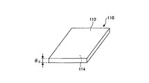
図4には、ダミーガラス板の一態様を模式的に示す。 FIG. 4 schematically shows one aspect of the dummy glass plate.
図4に示すように、ダミーガラス板110は、相互に対向する第1の表面112および第2の表面114を有する。なお、以降の説明では、後述するガラス板との混同を避けるため、ダミーガラス板110に関する各用語を表す際に、「ダミー」と言う用語を付加して示す。従って、第1の表面112および第2の表面114は、それぞれ、第1のダミー表面112および第2のダミー表面114と表記される。
As shown in FIG. 4, the
ダミーガラス板110は、厚さθDを有する。厚さθDは、後述する湿式エッチング処理によって完全に消失するような厚さでなければ、その値は、特に限られない。
The
次に、ダミーガラス板110の第1のダミー表面112の側から、レーザ光が照射される。これにより、ダミーガラス板110に初期ダミー特徴物が形成される。
Next, laser light is irradiated from the
ここで、「初期ダミー特徴物」とは、レーザ光照射によりダミーガラス板110に生じ得る、任意の構造を意味する。
Here, the “initial dummy feature” means an arbitrary structure that can be generated in the
例えば、「初期ダミー特徴物」は、貫通孔または非貫通孔のような「孔」であっても良い。 For example, the “initial dummy feature” may be a “hole” such as a through hole or a non-through hole.
あるいは、「初期ダミー特徴物」は、ダミーガラス板110の第1のダミー表面112から第2のダミー表面114に向かって配列された、複数のボイドで構成されたボイド列であっても良い。
Alternatively, the “initial dummy feature” may be a void row composed of a plurality of voids arranged from the
また、「初期ダミー特徴物」は、ダミーガラス板110の第1の表面112から第2の表面114に向かってライン状に形成された、改質層(「改質ライン」とも称される)であっても良い。
The “initial dummy feature” is a modified layer (also referred to as a “modified line”) formed in a line shape from the
なお、初期ダミー特徴物130についての詳細は、後述する「初期特徴物」に関する説明を参照することにより、より良く理解することができる。
The details of the
レーザ光は、ダミーガラス板110に、そのような初期ダミー特徴物を形成することができる限り、その種類および照射条件は限られない。例えば、初期ダミー特徴物が貫通孔または非貫通孔のような「孔」の場合、レーザ光は、例えばCO2レーザまたはUVレーザ等であっても良い。また、例えば、初期ダミー特徴物がボイド列の場合、レーザ光は、例えばフェムト秒レーザ等であっても良い。さらに、初期ダミー特徴物が改質ラインの場合、レーザ光は、例えばピコ秒レーザ等であっても良い。
As long as such initial dummy features can be formed on the
図5には、レーザ光照射により、ダミーガラス板110に初期ダミー特徴物130が形成された様子を示す。
FIG. 5 shows a state in which the
なお、初期ダミー特徴物130の数は特に限られず、初期ダミー特徴物130は、2つ以上であっても良い。 The number of initial dummy features 130 is not particularly limited, and the number of initial dummy features 130 may be two or more.
初期ダミー特徴物130は、ダミーガラス板110の第1のダミー表面112に、特徴部分132を有する。
The
特徴部分132の形態は、初期ダミー特徴物130の種類によって変化する。例えば、特徴部分132は、孔の開口、ボイド、または改質領域である。
The form of the
ここで、特徴部分132の直径をφ1とする。直径φ1は、特徴部分132の形態によっても変化するが、例えば、1μm〜100μmの範囲であっても良い。ただし、初期ダミー特徴物130が改質ラインの場合、特徴部分132の直径φ1は、1μm未満であっても良い。
Here, the diameter of the
(工程S113)
次に、初期ダミー特徴物130を有するダミーガラス板110が湿式エッチングされる。これにより、ダミーガラス板110の厚さが減少する。また、初期ダミー特徴物130が貫通孔に変化する。
(Step S113)
Next, the
この工程S113では、ダミーガラス板110が様々な厚さ減少量となるように、ダミーガラス板110を湿式エッチングすることにより、ダミーガラス板110のエッチング量E(厚さの減少量)と、孔の第1のダミー表面112における直径(換言すれば、湿式エッチング後の特徴部分132の直径)φとの間の関係が把握される。
In this step S113, the
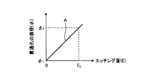
図6には、エッチング量Eと、孔の第1のダミー表面112における直径φとの間の関係(以下、「E−φ関係」という)の一例を、模式的に示す。 FIG. 6 schematically shows an example of the relationship between the etching amount E and the diameter φ of the hole at the first dummy surface 112 (hereinafter referred to as “E-φ relationship”).
図6に示した例では、エッチング量Eと孔の第1のダミー表面112における直径φの間には、一次、すなわち直線Aの相関がある。しかしながら、これは単なる一例であって、E−φ関係は、2次関数または指数関数など、より複雑な関係であっても良い。
In the example shown in FIG. 6, there is a first-order correlation, that is, a straight line A, between the etching amount E and the diameter φ of the hole at the
なお、この工程では、ダミーガラス板110は、全体が湿式エッチングされても、第2のダミー表面114がマスキング(マスク処理)された状態で、湿式エッチングされても良い。マスキングは、例えばフィルムを貼る、レジストなどでコーティングするなどの処理を行えばよい。湿式エッチング後には、フィルムやコーティング層は除去すればよい。
In this step, the entire
(工程S115〜工程S117)
次に、図6に示すように、得られたE−φ関係から、貫通孔の第1のダミー表面112における直径(すなわち特徴部分132の直径)を、φ1からφfにするためのエッチング量Etが算定される。
(Step S115 to Step S117)
Next, as shown in FIG. 6, from the obtained E-φ relationship, the diameter of the through hole on the first dummy surface 112 (that is, the diameter of the feature portion 132) is etched to change from φ 1 to φ f. The quantity Et is calculated.
また、算定結果から、以下の(1)式に基づいて、
θ1=θf+Et (1)式
被処理ガラス板の厚さθ1が定められる。
Also, from the calculation results, based on the following equation (1):
θ 1 = θ f + E t (1) Formula
A thickness θ 1 of the glass plate to be processed is determined.
以上のステップにより、被処理ガラス板の厚さθ1を算定することができる。 Through the above steps, the thickness θ 1 of the glass plate to be processed can be calculated.
(工程S120)
次に、実際の処理に供されるガラス板が準備される。被処理用のガラス板(被処理ガラス板)は、前述の工程S110で定められた厚さθ1を有する。
(Process S120)
Next, a glass plate for actual processing is prepared. The glass plate for processing (the glass plate to be processed) has the thickness θ 1 determined in the above-described step S110.
なお、通常の場合、厚さθ1は、例えば、50μm〜1000μmの範囲である。 In the case of normal thickness theta 1 is, for example, in the range of 50Myuemu~1000myuemu.
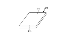
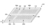
図7には、被処理ガラス板210の一態様を模式的に示す。ガラス板210は、相互に対向する第1の表面212および第2の表面214を有する。
FIG. 7 schematically shows one mode of the
図7に示した例では、ガラス板210は、略矩形状(例えば、パネル形状)の形態を有する。ただし、これは単なる一例であって、ガラス板210の形状は、特に限られず、例えば略円形状(例えば、ウェハ形状)であっても良い。
In the example shown in FIG. 7, the
また、ガラス板210は、前述のダミーガラス板110と同じ組成を有する限り、その製造方法は特に限られない。例えば、ガラス板210は、フロート法、フュージョン法、およびダウンドロー法など、いかなる従来の方法で製造されても良い。
Moreover, as long as the
この中では、特に、ガラス板210の厚さの制御が容易に行えるという特徴を有するため、フュージョン法が好ましい。
Among these, the fusion method is preferable because it has a feature that the thickness of the
例えば、フュージョン法では、単位時間当たりのフュージョンパイプから流出するガラスの体積をM(mm3/sec)とし、鉛直方向における引張速度をv(mm/sec)とし、ガラス板の幅をW(mm)としたとき、ガラス板の厚さt(mm)は、
t=M/(W×v) (2)式
で表される。幅W、厚さtは、フュージョンパイプの流出口側のものとする。
For example, in the fusion method, the volume of glass flowing out from the fusion pipe per unit time is M (mm 3 / sec), the tensile speed in the vertical direction is v (mm / sec), and the width of the glass plate is W (mm ), The thickness t (mm) of the glass plate is
t = M / (W × v) Equation (2)
It is represented by The width W and the thickness t are those on the outlet side of the fusion pipe.
従って、体積M、引張速度v、および幅Wを制御することにより、厚さtの制御を比較的容易に行うことができる。このように、フュージョン法では、厚さθ1のガラス板210を比較的容易に製造することができる。
Therefore, by controlling the volume M, the tensile speed v, and the width W, the thickness t can be controlled relatively easily. Thus, in the fusion process, it is possible to relatively easily produce a
(工程S130)
次に、ガラス板210の第1の表面212の側からレーザ光を照射することにより、ガラス板210に1または2以上の「初期特徴物」が形成される。
(Step S130)
Next, by irradiating laser light from the
前述のように、「初期特徴物」とは、レーザ光照射によりガラス板210に生じ得る、任意の構造を意味する。
As described above, the “initial feature” means any structure that can be generated in the
例えば、「初期特徴物」は、貫通孔または非貫通孔のような「孔」であっても良い。なお、そのような「孔」は、後の工程S140で形成される「孔」と区別するため、特に「初期孔」と称される。また、同様の理由から、この工程で形成される貫通孔および非貫通孔は、それぞれ、「初期貫通孔」および「初期非貫通孔」と称される。 For example, the “initial feature” may be a “hole” such as a through hole or a non-through hole. Such “holes” are particularly referred to as “initial holes” in order to distinguish them from the “holes” formed in the subsequent step S140. For the same reason, the through hole and the non-through hole formed in this step are referred to as an “initial through hole” and an “initial non-through hole”, respectively.
あるいは、「初期特徴物」は、ガラス板210の第1の表面212から第2の表面214に向かって配列された、複数のボイドで構成されたボイド列であっても良い。
Alternatively, the “initial feature” may be a void array composed of a plurality of voids arranged from the
また、「初期特徴物」は、ガラス板210の第1の表面212から第2の表面214に向かってライン状に形成された、改質層であっても良い。そのような改質層は、「改質ライン」とも称される。
The “initial feature” may be a modified layer formed in a line shape from the
さらに、「初期特徴物」は、初期貫通孔、初期非貫通孔、ボイド列、および改質ラインから選択された、2以上を含んでも良い。 Furthermore, the “initial feature” may include two or more selected from an initial through hole, an initial non-through hole, a void row, and a reforming line.
なお、この工程S130で使用されるレーザ光の種類および照射条件は、前述の工程S110においてダミーガラス板110に照射されたレーザ光の種類および照射条件と同じである。
The type and irradiation conditions of the laser beam used in this step S130 are the same as the type and irradiation conditions of the laser beam irradiated on the
例えば、初期特徴物が初期貫通孔または初期非貫通孔の場合、レーザ光は、例えばCO2レーザまたはUVレーザ等であっても良い。また、例えば、初期特徴物がボイド列の場合、レーザ光は、例えばフェムト秒レーザ等であっても良い。さらに、初期特徴物が改質ラインの場合、レーザ光は、例えばピコ秒レーザ等であっても良い。 For example, when the initial feature is an initial through hole or an initial non-through hole, the laser light may be, for example, a CO 2 laser or a UV laser. For example, when the initial feature is a void array, the laser light may be, for example, a femtosecond laser. Further, when the initial feature is a reforming line, the laser beam may be, for example, a picosecond laser.
図8には、ガラス板210に多数の初期特徴物230が形成された状態を模式的に示す。
FIG. 8 schematically shows a state in which a large number of
図8に示すように、各初期特徴物230は、ガラス板210の第1の表面212に、直径φ1の寸法を有するように形成される。換言すれば、各初期特徴物230は、ガラス板210の第1の表面212に、直径φ1の特徴部分232を有する。
As shown in FIG. 8, each
例えば、初期特徴物230が貫通孔または非貫通孔の場合、特徴部分232は、第1の表面212に存在する直径φ1の開口となる。また、初期特徴物230が改質ラインの場合、特徴部分232は、第1の表面212に存在する直径φ1の改質領域となる。一方、初期特徴物230がボイド列の場合、特徴部分232は、第1の表面212に存在する直径φ1の開口または改質領域となる。
For example, when the
特徴部分232の直径φ1は、初期特徴物230の種類によっても変化するが、例えば、1μm〜100μmの範囲であっても良い。ただし、初期特徴物230が改質ラインの場合、特徴部分232の直径φ1は、1μm未満であっても良い。
Diameter phi 1 of the
なお、図8に示した例では、ガラス板210の第1の表面212には、等間隔に配置された7行×7列の初期特徴物230が形成されている。しかしながら、これは単なる一例であって、初期特徴物230の数、および配置の態様は特に限られないことに留意する必要がある。
In the example shown in FIG. 8, the
(工程S140)
次に、初期特徴物230を有するガラス板210が湿式エッチングされる。これにより、初期特徴物230から貫通孔が形成される。
(Process S140)
Next, the
例えば、初期特徴物230が初期貫通孔の場合、湿式エッチングによって、初期特徴物230の断面が拡張され、より大きな貫通孔に変化する。また、初期特徴物230が初期非貫通孔の場合、湿式エッチングによって、非貫通孔は、第1の表面212から第2の表面214まで貫通する貫通孔に変化する。また、初期特徴物230がボイド列の場合、湿式エッチングによって、ボイド列を構成する各ボイドが接続され、第1の表面から第2の表面まで貫通する貫通孔が形成される。さらに、初期特徴物230が改質ラインの場合、湿式エッチングによって、改質部分が除去され、第1の表面212から第2の表面214まで貫通する貫通孔が形成される。
For example, when the
いずれの場合も、初期特徴物230の第1の表面212における直径は、特徴部分232の段階でのφ1からφ2に拡張される。
In any case, the diameter of the
ここで、湿式エッチングの条件は、ガラス板210のエッチング量Eが前述のEtとなるように選定される。(1)式から明らかなように、この場合、湿式エッチング処理により、ガラス板210の厚さθ1は、θfに変化する。
Here, the conditions of the wet etching, the etching amount E of the
また、湿式エッチング処理後に得られる貫通孔の第1の表面212における直径φ2は、前述のE−φ関係から、φfと等しくなる。
In addition, the diameter φ 2 of the
その結果、湿式エッチング後には、第1の表面212において所望の貫通孔の直径(φf)を有する、所望の厚さ(θf)のガラス基板を得ることができる。
As a result, a glass substrate having a desired thickness (θ f ) having a desired through-hole diameter (φ f ) on the
このように、第1の製造方法では、従来方法のような問題、すなわち孔の寸法を調整するための湿式エッチング工程の実施後に、ガラス基板の厚さが目標厚さθfから逸脱してしまうという問題を、有意に解消または抑制することが可能となる。 As described above, in the first manufacturing method, the thickness of the glass substrate deviates from the target thickness θ f after performing the problem as in the conventional method, that is, the wet etching process for adjusting the hole size. This problem can be solved or suppressed significantly.
なお、ガラス板(ガラス基板)の厚さは、マイクロメーターやレーザ変位計など一般的な寸法測定装置を用いて測定することができる。 The thickness of the glass plate (glass substrate) can be measured using a general dimension measuring device such as a micrometer or a laser displacement meter.
初期特徴物の直径φ1や形成された孔の直径φfは、レーザ顕微鏡や画像測定システム(例えば、ニコン社製のNEXIV)を用いて測定することができる。ここで、初期特徴物の上面から見た形状が正円でない場合は、最大径を直径φ1とする。 The diameter φ 1 of the initial feature and the diameter φ f of the formed hole can be measured using a laser microscope or an image measurement system (for example, NEXIV manufactured by Nikon Corporation). The shape viewed from the top of the initial characteristics thereof may not be a perfect circle, the maximum diameter to the diameter phi 1.
(本発明の一実施形態による孔を有するガラス基板の別の製造方法)
前述のような第1の製造方法では、工程S120で準備されるガラス板210は、厚さを除き、工程S140後に得られるガラス基板と実質的に同等の寸法(以下、「縦横寸法」と称する)を有する(ただし、より正確には、厚さの減少分と相応の寸法減少が生じる)。換言すれば、ガラス板210の第1および第2の表面212、214の見かけの面積は、(湿式エッチングによる僅かの低下はあるものの、)ガラス基板に加工された後も、あまり変化しない。
(Another manufacturing method of a glass substrate having holes according to an embodiment of the present invention)
In the first manufacturing method as described above, the
一方、通常の場合、ガラス板の縦横寸法とガラス基板の縦横寸法とは、一致しない場合が多い。すなわち、通常は、工程の途中に、ガラス板を所定の寸法に切断して、ガラス板から1または2以上のガラスピースを採取する工程(切断工程)が実施される。 On the other hand, in normal cases, the vertical and horizontal dimensions of the glass plate and the vertical and horizontal dimensions of the glass substrate often do not match. That is, usually, a step (cutting step) of cutting one or two or more glass pieces from the glass plate by cutting the glass plate into a predetermined size during the process is performed.
そこで、次に、図9〜図11を参照して、切断工程を含む本発明の一実施形態について説明する。 Then, next, with reference to FIGS. 9-11, one Embodiment of this invention including a cutting process is described.
図9には、本発明の一実施形態による、孔を有するガラス基板の別の製造方法のフローを概略的に示す。また、図10〜図11には、本発明の一実施形態による孔を有するガラス基板の別の製造方法における各工程の態様を模式的に示す。 FIG. 9 schematically shows a flow of another method for manufacturing a glass substrate having holes according to an embodiment of the present invention. 10 to 11 schematically show aspects of each step in another method for producing a glass substrate having holes according to an embodiment of the present invention.
図9に示すように、本発明の一実施形態による貫通孔を有するガラス基板の別の製造方法(以下、「第2の製造方法」という)は、
(1)被処理ガラス板の厚さθ1を定める工程(工程S210)と、
(2)相互に対向する第1および第2の表面を有し、厚さθ1を有するガラス板を準備する工程(工程S220)と、
(3)前記ガラス板の前記第1の表面の側からレーザ光を照射することにより、前記ガラス板に1または2以上の初期特徴物を形成する工程であって、前記初期特徴物は、前記第1の表面に直径φ1の寸法を有する、工程(工程S230)と、
(4)前記ガラス板を切断して、前記初期特徴物を含むガラスピースを得る工程(工程S240)と、
(5)前記初期特徴物を有するガラスピースを湿式エッチングする工程であって、これにより、前記初期特徴物から、前記第1の表面に直径φfを有する孔が形成されるとともに、前記ガラスピースの厚さがθ1から、前記目標値θfに調整される工程(工程S250)と、
を有する。
As shown in FIG. 9, another method for manufacturing a glass substrate having a through hole according to an embodiment of the present invention (hereinafter referred to as “second manufacturing method”) is as follows.
(1) a step of determining the thickness θ 1 of the glass plate to be treated (step S210);
(2) preparing a glass plate having first and second surfaces facing each other and having a thickness θ 1 (step S220);
(3) A step of forming one or more initial features on the glass plate by irradiating laser light from the first surface side of the glass plate, wherein the initial features are A step (step S230) having a dimension of diameter φ 1 on the first surface;
(4) cutting the glass plate to obtain a glass piece containing the initial feature (step S240);
(5) wet etching the glass piece having the initial feature, whereby a hole having a diameter φ f is formed in the first surface from the initial feature, and the glass piece A step (step S250) in which the thickness of is adjusted from θ 1 to the target value θ f ,
Have
以下、図10〜図11を参照して、各工程について詳しく説明する。なお、ここでは、一例として、工程S250で形成される孔が貫通孔であり、従って、第2の製造方法が貫通孔を有するガラス基板を製造する方法である場合を想定して、各工程について説明する。ただし、以下の記載が、非貫通孔を有するガラス基板の製造方法にも同様に適用できることは、当業者には明らかである。 Hereinafter, each step will be described in detail with reference to FIGS. Here, as an example, assuming that the hole formed in step S250 is a through-hole, and therefore the second manufacturing method is a method of manufacturing a glass substrate having a through-hole, each step is assumed. explain. However, it will be apparent to those skilled in the art that the following description can be similarly applied to a method of manufacturing a glass substrate having non-through holes.
また、第2の製造方法において、工程S210〜工程230は、それぞれ、第1の製造方法における工程S110〜工程130と同様であり、前述の記載が参照できる。 In the second manufacturing method, steps S210 to 230 are the same as steps S110 to 130 in the first manufacturing method, respectively, and the above description can be referred to.
そこで、ここでは、工程S240以降について説明する。 Therefore, here, step S240 and subsequent steps will be described.
(工程S240)
第2の製造方法では、工程S230までの実施により、ガラス板に初期特徴物が形成される。
(Step S240)
In the second manufacturing method, initial features are formed on the glass plate by performing up to step S230.
図10には、初期特徴物を有するガラス板の一態様を模式的に示す。 FIG. 10 schematically shows one embodiment of a glass plate having initial features.
図10に示すように、ガラス板310は、相互に対向する第1の表面312および第2の表面314を有し、厚さはθ1である。
As shown in FIG. 10, the
ガラス板310には、多数の初期特徴物330が形成されている。
A number of
ここで、ガラス板310の第1の表面312において、破線で囲まれた、複数の初期特徴物330を含む仮想領域を「被切断領域」と称する。「被切断領域」は、後に製造されるガラス基板の区画を定める目安となる。換言すれば、「被切断領域」は、最終的に製造されるガラス基板の寸法に合わせて配置される。
Here, on the
図10の例では、第1の表面312に、第1の被切断領域340a〜第4の被切断領域340dの4つの被切断領域が配置されている。
In the example of FIG. 10, four regions to be cut, which are a
第1の被切断領域340aには、初期特徴物330が縦5列×横5行のマトリクス状に配置されており、第2の被切断領域340bには、初期特徴物330が縦15列×横5行のマトリクス状に配置されている。また、第3の被切断領域340cには、初期特徴物330が縦5列×横5行のマトリクス状に配置されており、第4の被切断領域340dには、初期特徴物330が縦15列×横5行のマトリクス状に配置されている。
In the
しかしながら、これは、単なる一例に過ぎず、各被切断領域に含まれる初期特徴物330の数および配列方式は、特に限られない。典型的な例では、各被切断領域に、10,000個〜1,000,000個の範囲の初期特徴物330が存在する場合がある。
However, this is merely an example, and the number and arrangement method of the
なお、各被切断領域に存在する初期特徴物330の数は、相互に異なっていても良い。
It should be noted that the number of
次に、ガラス板310が切断される。この際には、各被切断領域340a〜340dが相互に分離されるようにして、ガラス板310が切断される。換言すれば、ガラス板310は、切断後のガラスピースが、それぞれの被切断領域340a〜340dを有するように切断される。
Next, the
切断方法は、ガラス板310が切断できれば特に限定されない。例えば、ガラス板310は、ダイアモンドホイールにより切断されても良い。
The cutting method is not particularly limited as long as the
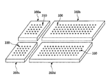
図11には、ガラス板310の切断後の状態を模式的に示す。
In FIG. 11, the state after the cutting | disconnection of the
図11に示すように、ガラス板310の切断により、ガラスピース350a〜350dが採取される。より具体的には、ガラス板310を第1の被切断領域340aを含むように、またはこれと一致する位置で切断することにより、第1のガラスピース350aが採取される。同様に、ガラス板310を第2の被切断領域340bを含むように、またはこれと一致する位置で切断することにより、第2のガラスピース350bが採取され、ガラス板310を第3の被切断領域340cを含むように、またはこれと一致する位置で切断することにより、第3のガラスピース350cが採取され、ガラス板310を第4の被切断領域340dを含むように、またはこれと一致する位置で切断することにより、第4のガラスピース350dが採取される。なお、図11では略矩形状(例えば、パネル形状)のガラスピースを採取する例を示したが、採取される形状は特に限定されず、略円形状(例えば、ウェハ形状)であってもよい。
As shown in FIG. 11,
(工程S250)
その後は、各ガラスピース350a〜350dに対して、前述の工程S140において説明したような、湿式エッチング工程が実施される。
(Process S250)
Thereafter, the wet etching process as described in the above-described process S140 is performed on each of the
採取された各ガラスピース350a〜350dを湿式エッチングすることにより、切断面が面取りされるとともに、ガラス基板の強度が向上する。
By wet-etching the collected
以上の工程により、第1の表面312において所望の貫通孔の直径(φf)を有し、所望の厚さ(θf)のガラス基板を製造することができる。
Through the above steps, a glass substrate having a desired through-hole diameter (φ f ) on the
このような第2の製造方法においても、従来方法のような問題、すなわち孔の寸法を調整するための湿式エッチング工程の実施後に、ガラス基板の厚さが目標厚さθfから逸脱してしまうという問題を、有意に解消または抑制することができる。 Even in such a second manufacturing method, the thickness of the glass substrate deviates from the target thickness θ f after performing the problem as in the conventional method, that is, the wet etching step for adjusting the hole size. This problem can be solved or suppressed significantly.
ここで、ガラス板にレーザ光を照射して、初期特徴物を形成する場合、レーザ加工中のガラス板の移動を抑制するため、しばしば吸着テーブルが利用される。吸着テーブルは、上部にガラス板を吸引固定する機能を有する。このため、吸着テーブル上でガラス板のレーザ加工を実施することにより、ガラス板の加工中の移動が抑制され、所定の位置に初期特徴物を形成することができる。 Here, when an initial feature is formed by irradiating a glass plate with laser light, a suction table is often used to suppress movement of the glass plate during laser processing. The suction table has a function of sucking and fixing a glass plate on the top. For this reason, by carrying out laser processing of the glass plate on the suction table, movement during processing of the glass plate is suppressed, and an initial feature can be formed at a predetermined position.
しかしながら、一般に、孔を有するガラス基板の寸法は、用途によって様々であり、そのため、従来の一般的な方法で孔を有するガラス基板を製造する場合、ガラス基板の寸法に適応した各種寸法の吸着テーブルが必要となる。そのような吸着テーブルの製造には、相応の時間およびコストが必要となり、その結果、ガラス基板の製造効率および製造コストが上昇してしまうという問題がある。 However, in general, the size of the glass substrate having holes varies depending on the application. Therefore, when manufacturing a glass substrate having holes by a conventional general method, the suction table having various sizes adapted to the size of the glass substrate. Is required. Appropriate time and cost are required for manufacturing such a suction table, and as a result, there is a problem that the manufacturing efficiency and manufacturing cost of the glass substrate increase.
これに対して、第2の製造方法では、最終的に必要なガラス基板の寸法に関わらず、工程S230においてレーザ加工されるガラス板として、常に同じ寸法のガラス板を使用することができる。ガラス板は、工程S240において、ガラス基板の寸法に対応するガラスピースとして分離されるためである。 On the other hand, in the second manufacturing method, a glass plate having the same size can always be used as the glass plate to be laser processed in step S230 regardless of the finally required size of the glass substrate. This is because the glass plate is separated as glass pieces corresponding to the dimensions of the glass substrate in step S240.
従って、第2の製造方法では、従来のように、様々な吸着テーブルを準備する必要がなくなる。すなわち、第2の製造方法では、ガラス板に適合する寸法を有する一つの吸着テーブルを準備しておけば、この吸着テーブルにより、いかなる寸法のガラス基板も製造することができる。 Therefore, in the second manufacturing method, it is not necessary to prepare various suction tables as in the prior art. That is, in the second manufacturing method, if one suction table having a size that fits the glass plate is prepared, a glass substrate of any size can be manufactured using this suction table.
その結果、第2の製造方法では、ガラス基板の製造効率および製造コストを有意に抑制することが可能となる。 As a result, in the second manufacturing method, it is possible to significantly suppress the manufacturing efficiency and manufacturing cost of the glass substrate.
(本発明の一実施形態による孔を有するガラス基板のさらに別の製造方法)
次に、図12を参照して、本発明の一実施形態による孔を有するガラス基板のさらに別の製造方法の一例について説明する。
(Still another method of manufacturing a glass substrate having holes according to an embodiment of the present invention)
Next, with reference to FIG. 12, an example of still another method for manufacturing a glass substrate having holes according to an embodiment of the present invention will be described.
図12には、本発明の一実施形態による孔を有するガラス基板のさらに別の製造方法のフローを概略的に示す。 FIG. 12 schematically shows a flow of still another method for manufacturing a glass substrate having holes according to an embodiment of the present invention.
図12に示すように、本発明の一実施形態による貫通孔を有するガラス基板のさらに別の製造方法(以下、「第3の製造方法」という)は、
(1)被処理ガラス板の厚さθ1を定める工程(工程S310)と、
(2)相互に対向する第1および第2の表面を有し、厚さθ1を有するガラス板を準備する工程(工程S320)と、
(3)前記ガラス板の前記第1の表面の側からレーザ光を照射することにより、前記ガラス板に1または2以上の初期特徴物を形成する工程であって、前記初期特徴物は、前記第1の表面に直径φ1の寸法を有する、工程(工程S330)と、
(4)前記初期特徴物を有するガラス板を湿式エッチングする工程であって、これにより、前記初期特徴物から、所望の開口寸法を有する孔が形成されるとともに、前記ガラス板の厚さがθ1から、目標値θfに調整される工程(工程S340)と、
(5)前記ガラス板を切断して、前記孔を含むガラス基板を得る工程(工程S350)と、
を有する。
As shown in FIG. 12, still another method for manufacturing a glass substrate having a through hole according to an embodiment of the present invention (hereinafter referred to as “third manufacturing method”)
(1) a step of determining the thickness θ 1 of the glass plate to be processed (step S310);
(2) preparing a glass plate having first and second surfaces facing each other and having a thickness θ 1 (step S320);
(3) A step of forming one or more initial features on the glass plate by irradiating laser light from the first surface side of the glass plate, wherein the initial features are A step (step S330) having a dimension of diameter φ 1 on the first surface;
(4) A step of wet-etching the glass plate having the initial feature, whereby a hole having a desired opening size is formed from the initial feature, and the thickness of the glass plate is θ 1 to the step of adjusting the target value θ f (step S340),
(5) cutting the glass plate to obtain a glass substrate including the holes (step S350);
Have
この第3の製造方法は、前述の図9〜図11を参照して示した第2の製造方法とほぼ同様の工程を有する。ただし、第3の製造方法では、ガラス板を切断してガラス基板を得る工程(工程S350)が、湿式エッチング(工程S340)後に実施される点で、前述の第2の製造方法とは異なっている。 This third manufacturing method has substantially the same steps as the second manufacturing method shown with reference to FIGS. However, the third manufacturing method differs from the second manufacturing method described above in that the step of cutting the glass plate to obtain the glass substrate (step S350) is performed after the wet etching (step S340). Yes.
第3の製造方法における各工程S310〜S350は、前述の第2の製造方法における各工程から明らかである。そのため、第3の製造方法における各工程の詳細な説明は、省略する。 Each process S310-S350 in the 3rd manufacturing method is clear from each process in the above-mentioned 2nd manufacturing method. Therefore, detailed description of each process in the third manufacturing method is omitted.
第3の製造方法においても、従来方法のような問題、すなわち孔の寸法を調整するための湿式エッチング工程の実施後に、ガラス基板の厚さが目標厚さθfから逸脱してしまうという問題を、有意に解消または抑制することができる。 Even in the third manufacturing method, there is a problem as in the conventional method, that is, the problem that the thickness of the glass substrate deviates from the target thickness θ f after the wet etching step for adjusting the hole size is performed. , Can be significantly eliminated or suppressed.
また、第3の製造方法においても、第2の製造方法の場合と同様の効果、すなわち従来のように、様々な吸着テーブルを準備する必要がなくなり、ガラス基板の製造効率および製造コストを有意に抑制することができるという効果を得ることができる。 In the third manufacturing method, the same effect as in the second manufacturing method, that is, there is no need to prepare various suction tables as in the prior art, and the glass substrate manufacturing efficiency and manufacturing cost are significantly increased. The effect that it can suppress can be acquired.
なお、第3の製造方法において、(4)の工程と(5)の工程の間に、孔内に充填材を設置する工程を実施しても良い。 In the third manufacturing method, a step of installing a filler in the hole may be performed between the step (4) and the step (5).
充填材は、導電性材料を有する。導電性材料は、例えば、金、銀、銅、ニッケル、アルミニウム、ネオジム、モリブデン、および/またはタングステン、あるいはこれらを含む合金で構成されても良い。例えば、導電性材料は、アルミニウム−ネオジム合金またはモリブデン−タングステン合金で構成されても良い。 The filler has a conductive material. The conductive material may be made of, for example, gold, silver, copper, nickel, aluminum, neodymium, molybdenum, and / or tungsten, or an alloy containing these. For example, the conductive material may be composed of an aluminum-neodymium alloy or a molybdenum-tungsten alloy.
孔に充填材を充填する方法は、特に限られない。例えば、充填材は、無電解めっき法により、孔に充填されても良い。あるいは、充填材は、導電性ペーストや導電性微粒子のスクリーン印刷法により、孔に充填されても良い。 The method for filling the holes with the filler is not particularly limited. For example, the filler may be filled in the holes by an electroless plating method. Alternatively, the filler may be filled in the holes by a screen printing method of conductive paste or conductive fine particles.
この段階で、孔内に充填材を設置する工程を実施することにより、(5)の工程後に採取された各ガラス基板毎に充填材の充填工程を実施する必要がなくなるため、効率的な充填処理が可能となる。また、これにより、製造効率および製造コストをよりいっそう抑制することが可能となる。 At this stage, by performing the process of installing the filler in the hole, it is not necessary to perform the filler filling process for each glass substrate collected after the process of (5), so efficient filling Processing is possible. This also makes it possible to further suppress the manufacturing efficiency and the manufacturing cost.
以上、第1の製造方法〜第3の製造方法を参照して、本発明の一実施形態について説明した。しかしながら、本発明は、これらの形態に限られるものではない。 The embodiment of the present invention has been described above with reference to the first to third manufacturing methods. However, the present invention is not limited to these forms.
例えば、上記の説明例では、最終的に、貫通孔を有するガラス基板が製造される。 For example, in the example described above, a glass substrate having a through hole is finally manufactured.
しかしながら、これとは別に、最終的に、非貫通孔を有するガラス基板が製造されても良い。この場合、初期特徴物は、初期非貫通孔、ボイド列、または改質ラインであっても良い。 However, separately from this, finally, a glass substrate having a non-through hole may be manufactured. In this case, the initial feature may be an initial non-through hole, a void row, or a reforming line.
例えば、初期特徴物が初期非貫通孔の場合、湿式エッチングによって、初期非貫通孔は、第1の表面により大きな開口を有する非貫通孔に変化しても良い。また、初期特徴物がボイド列の場合、湿式エッチングによって、ボイド列を構成する各ボイドが接続され、非貫通孔が形成されても良い。さらに、初期特徴物が改質ラインの場合、湿式エッチングによって、改質部分が除去され、非貫通孔が形成されても良い。 For example, when the initial feature is an initial non-through hole, the initial non-through hole may be changed to a non-through hole having a larger opening on the first surface by wet etching. In addition, when the initial feature is a void row, each void constituting the void row may be connected by wet etching to form a non-through hole. Further, when the initial feature is a modified line, the modified portion may be removed by wet etching to form a non-through hole.
この他にも、各種変更が可能である。 Various other changes are possible.
次に、本発明の実施例について説明する。 Next, examples of the present invention will be described.
(実施例1)
以下の方法により、非貫通孔を有するガラス基板を製造した。非貫通孔の第1の表面における直径(大きい方の開口の直径)は、40μmを目標とした(φf=40μm)。また、ガラス基板の厚さは、200μmを目標とした(θf=200μm)。
Example 1
A glass substrate having non-through holes was produced by the following method. The diameter of the first surface of the non-through hole (the diameter of the larger opening) was set to 40 μm (φ f = 40 μm). The target thickness of the glass substrate was 200 μm (θ f = 200 μm).
まず、縦50mm×横50mm×厚さ0.3mmのダミーガラス板(無アルカリガラス)を準備した。 First, a dummy glass plate (non-alkali glass) having a length of 50 mm × width of 50 mm × thickness of 0.3 mm was prepared.
このダミーガラス板に、第1の表面の側からレーザ光を照射し、初期非貫通孔を形成した。レーザ光の照射条件は、以下の通りである:
レーザ種:YAGレーザ(波長355μm)
レーザ出力10W。
The dummy glass plate was irradiated with laser light from the first surface side to form initial non-through holes. The laser light irradiation conditions are as follows:
Laser type: YAG laser (wavelength 355 μm)
Laser power 10W.
初期非貫通孔の第1の主表面の開口の直径(φ1)は、約12μmであった。 The diameter (φ 1 ) of the opening of the first main surface of the initial non-through hole was about 12 μm.
次に、各種条件でダミーガラス板を湿式エッチング処理し、エッチング量(厚さの減少量)Eと非貫通孔の開口直径φとの関係、すなわちE−φ関係を求めた。 Next, the dummy glass plate was wet-etched under various conditions, and the relationship between the etching amount (thickness reduction amount) E and the opening diameter φ of the non-through hole, that is, the E-φ relationship was obtained.
なお、ダミーガラス板は、第2の主表面をマスク処理した状態で、湿式エッチング処理に供した。従って、ガラス板の第2の主表面は、エッチングされていない。 In addition, the dummy glass plate was used for the wet etching process in the state which masked the 2nd main surface. Accordingly, the second main surface of the glass plate is not etched.
図13には、得られたE−φ関係のグラフを示す。 FIG. 13 shows a graph of the obtained E-φ relationship.
このグラフから、エッチング量Eと非貫通孔の開口の直径φとの間には、一次の関係が成立することがわかった。また、この結果から、直径φf=40μmのガラス基板を得るためには、約16μmのエッチング量(Et)が必要であることがわかった。 From this graph, it was found that a primary relationship was established between the etching amount E and the diameter φ of the opening of the non-through hole. Further, it was found from this result that an etching amount (E t ) of about 16 μm is necessary to obtain a glass substrate having a diameter φ f = 40 μm.
この結果に基づき、(1)式
θ1=θf+Et (1)式
に従って準備するガラス板の厚さ(θ1)を求めると、θ1=216μmとなった。
Based on this result, equation (1)
θ 1 = θ f + E t (1) Formula
When the thickness (θ 1 ) of the glass plate prepared according to the above was determined, it was θ 1 = 216 μm.
そこで、次に、縦300mm×横300mm×厚さ(θ1)216μmのガラス板(無アルカリガラス)を準備した。 Therefore, next, a glass plate (non-alkali glass) having a length of 300 mm × width of 300 mm × thickness (θ 1 ) of 216 μm was prepared.
また、このガラス板に対して、第1の表面の側からレーザ光を照射して、初期非貫通孔を形成した。レーザ光の照射条件は、ダミーガラス板において使用したものと同じとした。 In addition, the glass plate was irradiated with laser light from the first surface side to form initial non-through holes. The laser light irradiation conditions were the same as those used for the dummy glass plate.
初期非貫通孔の第1の表面における開口は、直径約12μmであった。 The opening in the first surface of the initial non-through hole was about 12 μm in diameter.
次に、このガラス板の第2の表面をマスキングした状態で、ガラス板を湿式エッチング処理した。湿式エッチングの条件は、エッチング量EがEt(=16μm)となる条件とした。 Next, the glass plate was wet-etched in a state where the second surface of the glass plate was masked. The wet etching conditions were such that the etching amount E was E t (= 16 μm).
湿式エッチング処理の後に、得られたガラス基板の厚さを測定したところ、厚さは、200μmであった。また、非貫通孔の第1の表面における開口の直径は、約40μmであった。 When the thickness of the obtained glass substrate was measured after the wet etching process, the thickness was 200 μm. Moreover, the diameter of the opening in the 1st surface of a non-through-hole was about 40 micrometers.
このように、所望の厚さθfを有し、所望の直径φfの非貫通孔を有するガラス基板が製造された。 Thus, a glass substrate having a desired thickness θ f and a non-through hole having a desired diameter φ f was manufactured.
(実施例2)
貫通孔を有するガラス基板を製造した。貫通孔の第1の表面における直径(大きい方の開口の直径)は、40μmを目標とした(φf=40μm)。また、ガラス基板の厚さは、200μmを目標とした(θf=200μm)。
(Example 2)
A glass substrate having a through hole was produced. The diameter (diameter of the larger opening) of the first surface of the through hole was set to 40 μm (φ f = 40 μm). The target thickness of the glass substrate was 200 μm (θ f = 200 μm).
まず、縦50mm×横50mm×厚さ0.3mmのダミーガラス板(無アルカリガラス)を準備した。 First, a dummy glass plate (non-alkali glass) having a length of 50 mm × width of 50 mm × thickness of 0.3 mm was prepared.
このダミーガラス板に、第1の表面の側からレーザ光を照射し、初期貫通孔を形成した。レーザ光の照射条件は、以下の通りである:
レーザ種:YAGレーザ(波長355μm)
レーザ出力10W。
The dummy glass plate was irradiated with laser light from the first surface side to form initial through holes. The laser light irradiation conditions are as follows:
Laser type: YAG laser (wavelength 355 μm)
Laser power 10W.
初期貫通孔の第1の主表面の開口の直径(φ1)は、約12μmであった。 The diameter (φ 1 ) of the opening on the first main surface of the initial through hole was about 12 μm.
次に、各種条件でダミーガラス板を湿式エッチング処理し、エッチング量(厚さの減少量)Eと貫通孔の開口直径φとの関係、すなわちE−φ関係を求めた。 Next, the dummy glass plate was wet-etched under various conditions, and the relationship between the etching amount (thickness reduction amount) E and the opening diameter φ of the through hole, that is, the E-φ relationship was obtained.
なお、ダミーガラス板は、第2の主表面をマスク処理せず、全体を湿式エッチング処理した。 The dummy glass plate was not etched on the second main surface, but was wet etched.
図14には、得られたE−φ関係のグラフを示す。 FIG. 14 shows a graph of the obtained E-φ relationship.
このグラフから、エッチング量Eと貫通孔の開口の直径φとの間には、一次の関係が成立することがわかった。また、この結果から、直径φf=40μmのガラス基板を得るためには、約32μmのエッチング量(Et)が必要であることがわかった。 From this graph, it was found that a primary relationship was established between the etching amount E and the diameter φ of the opening of the through hole. Further, from this result, it was found that an etching amount (E t ) of about 32 μm was necessary to obtain a glass substrate having a diameter φ f = 40 μm.
この結果に基づき、(1)式
θ1=θf+Et (1)式
に従って準備するガラス板の厚さ(θ1)を求めると、θ1=232μmとなった。
Based on this result, equation (1)
θ 1 = θ f + E t (1) Formula
When the thickness (θ 1 ) of the glass plate to be prepared was determined according to the above, θ 1 = 232 μm.
そこで、次に、縦300mm×横300mm×厚さ(θ1)232μmのガラス板(無アルカリガラス)を準備した。 Then, next, a glass plate (non-alkali glass) having a length of 300 mm × width of 300 mm × thickness (θ 1 ) of 232 μm was prepared.
また、このガラス板に対して、第1の表面の側からレーザ光を照射して、初期貫通孔を形成した。レーザ光の照射条件は、ダミーガラス板において使用したものと同じとした。 Further, this glass plate was irradiated with laser light from the first surface side to form initial through holes. The laser light irradiation conditions were the same as those used for the dummy glass plate.
初期貫通孔の第1の表面における開口は、約12μmの直径を有した。 The opening in the first surface of the initial through hole had a diameter of about 12 μm.
次に、このガラス板全体を湿式エッチング処理した。湿式エッチングの条件は、エッチング量EがEt(=32μm)となる条件とした。 Next, the whole glass plate was wet-etched. The wet etching conditions were such that the etching amount E was E t (= 32 μm).
湿式エッチング処理の後に、得られたガラス基板の厚さを測定したところ、厚さは、200μmであった。また、貫通孔の第1の表面における開口の直径は、約40μmであった。 When the thickness of the obtained glass substrate was measured after the wet etching process, the thickness was 200 μm. Moreover, the diameter of the opening in the 1st surface of a through-hole was about 40 micrometers.
このように、所望の厚さθfを有し、所望の直径φfの貫通孔を有するガラス基板が製造された。 In this way, a glass substrate having a desired thickness θ f and a through hole having a desired diameter φ f was manufactured.
本発明は、例えば、ガラス基板に孔を形成する技術に利用することができる。また、本発明は、例えば、貫通電極を備えるガラス基板用のガラス基板の製造方法やインターポーザ(ガラスインターポーザ)用のガラス基板の製造方法に利用することができる。例えば、ガラス基板に形成する孔が貫通孔の場合、そのようなガラス基板の貫通孔に貫通電極を形成することにより、貫通電極付きガラス基板、およびインターポーザ(ガラスインターポーザ)を製造することができる。例えば、ガラス基板に形成する孔が非貫通孔の場合、そのようなガラス基板の孔内に貫通電極となる充填材を設置する前または設置した後に、研磨や研削などによりガラス基板を薄型化して、貫通電極付きガラス基板、およびインターポーザを製造することができる。 The present invention can be used, for example, in a technique for forming holes in a glass substrate. Moreover, this invention can be utilized for the manufacturing method of the glass substrate for glass substrates provided with a penetration electrode, and the manufacturing method of the glass substrate for interposers (glass interposer), for example. For example, when the hole formed in the glass substrate is a through hole, a glass substrate with a through electrode and an interposer (glass interposer) can be manufactured by forming a through electrode in the through hole of such a glass substrate. For example, when the hole formed in the glass substrate is a non-through hole, the glass substrate is thinned by polishing or grinding before or after installing the filler serving as the through electrode in the hole of the glass substrate. , Glass substrates with through electrodes, and interposers can be manufactured.
10 ガラス板
12 第1の表面
14 第2の表面
25 初期貫通孔
26a 第1の開口
26b 第2の開口
30 ガラス基板
35 貫通孔
110 ダミーガラス板
112 第1のダミー表面
114 第2のダミー表面
130 初期ダミー特徴物
132 特徴部分
210 ガラス板
212 第1の表面
214 第2の表面
230 初期特徴物
232 特徴部分
310 ガラス板
312 第1の表面
314 第2の表面
330 初期特徴物
340a 第1の被切断領域
340b 第2の被切断領域
340c 第3の被切断領域
340d 第4の被切断領域
350a〜350d ガラスピース
DESCRIPTION OF
Claims (10)
(1)被処理ガラス板の厚さθ1を定める工程と、
(2)相互に対向する第1および第2の表面を有し、前記厚さθ1を有するガラス板を準備する工程と、
(3)前記ガラス板の前記第1の表面の側からレーザ光を照射することにより、前記ガラス板に1または2以上の初期特徴物を形成する工程であって、前記初期特徴物は、前記第1の表面に直径φ1の寸法を有する、工程と、
(4)前記初期特徴物を有するガラス板を湿式エッチングする工程であって、これにより、前記初期特徴物から、前記第1の表面に直径φfを有する孔が形成されるとともに、前記ガラス板の厚さがθ1から、目標値θfに調整される工程と、
を有する製造方法。 A method of manufacturing a glass substrate having a thickness θ f having a hole having a diameter φ f ,
(1) a step of determining the thickness θ 1 of the glass plate to be treated;
(2) preparing a glass plate having first and second surfaces facing each other and having the thickness θ 1 ;
(3) A step of forming one or more initial features on the glass plate by irradiating laser light from the first surface side of the glass plate, wherein the initial features are Having a dimension of diameter φ 1 on the first surface;
(4) Wet etching the glass plate having the initial feature, whereby a hole having a diameter φ f is formed in the first surface from the initial feature, and the glass plate The thickness of is adjusted from θ 1 to the target value θ f ,
A manufacturing method comprising:
(i)前記ガラス板と同じ組成を有し、相互に対向する第1および第2のダミー表面を有するダミーガラス板に、前記第1のダミー表面の側から、前記(3)の工程と同じ条件で、前記レーザ光を照射することにより、前記ダミーガラス板に、初期ダミー特徴物を形成する工程であって、前記初期ダミー特徴物は、前記第1のダミー表面に直径φ1の寸法を有する、工程と、
(ii)前記ダミーガラス板を湿式エッチングして、前記ダミーガラス板のエッチング量と、前記初期ダミー特徴物がエッチングされることにより形成される孔の、前記第1のダミー表面における直径との関係を把握する工程と、
(iii)前記関係から、前記第1のダミー表面に直径φfの前記孔を得るためのエッチング量Etを定める工程と、
(iv)以下の式
θ1=θf+Et
から、前記被処理ガラス板の厚さθ1を定める工程と、
を有し、
前記(4)の工程では、前記エッチング量Etで前記ガラス板がエッチングされる、請求項1に記載の製造方法。 The step (1)
(I) A dummy glass plate having the same composition as that of the glass plate and having first and second dummy surfaces facing each other is the same as the step (3) from the side of the first dummy surface. The step of forming an initial dummy feature on the dummy glass plate by irradiating the laser beam under conditions, wherein the initial dummy feature has a diameter of φ 1 on the first dummy surface. Having a process;
(Ii) Relationship between the etching amount of the dummy glass plate by wet etching the dummy glass plate and the diameter of the hole formed by etching the initial dummy feature on the first dummy surface The process of grasping
(Iii) from the relationship, a step of determining an etching amount E t for obtaining said hole diameter phi f in the first dummy surface,
(Iv) The following formula
θ 1 = θ f + E t
From the step of determining the thickness θ 1 of the glass plate to be treated,
Have
In step (4), the glass plate in the etching amount E t is etched, the production method according to claim 1.
さらに、前記(3)の工程と(4)の工程の間に、
(5−1)前記ガラス板を切断して、前記初期特徴物を含むガラスピースを得る工程
を有し、
前記(4)の工程では、前記(5−1)で得られた前記ガラスピースが湿式エッチングされる、請求項1乃至4のいずれか一つに記載の製造方法。 The dimension of the glass plate in the step (2) is larger than the dimension of the glass substrate,
Furthermore, between the step (3) and the step (4),
(5-1) cutting the glass plate to obtain a glass piece containing the initial feature,
5. The manufacturing method according to claim 1, wherein in the step (4), the glass piece obtained in the step (5-1) is wet-etched.
さらに、前記(4)の工程の後に、
(5−2)前記ガラス板を切断して、前記孔を含むガラス基板を得る工程
を有する、請求項1乃至4のいずれか一つに記載の製造方法。 The dimension of the glass plate in the step (2) is larger than the dimension of the glass substrate,
Further, after the step (4),
(5-2) The manufacturing method as described in any one of Claims 1 thru | or 4 which has the process of cut | disconnecting the said glass plate and obtaining the glass substrate containing the said hole.
t=M/(W×v) (2)式
で表され、前記体積M、引張速度v、および幅Wの少なくとも一以上を制御することにより、前記厚さθ1を調整する、請求項7に記載の製造方法。 When the volume of the glass flowing out from the fusion pipe per unit time is M (mm 3 / sec), the tensile speed in the vertical direction is v (mm / sec), and the width of the glass plate is W (mm), the glass The thickness t (mm) of the plate is
t = M / (W × v) Equation (2)
The manufacturing method according to claim 7, wherein the thickness θ 1 is adjusted by controlling at least one of the volume M, the tensile speed v, and the width W.
Applications Claiming Priority (2)
| Application Number | Priority Date | Filing Date | Title |
|---|---|---|---|
| JP2016154627 | 2016-08-05 | ||
| JP2016154627 | 2016-08-05 |
Publications (1)
| Publication Number | Publication Date |
|---|---|
| JP2018024571A true JP2018024571A (en) | 2018-02-15 |
Family
ID=61072086
Family Applications (1)
| Application Number | Title | Priority Date | Filing Date |
|---|---|---|---|
| JP2017149004A Withdrawn JP2018024571A (en) | 2016-08-05 | 2017-08-01 | Manufacturing method of glass substrate having pores |
Country Status (2)
| Country | Link |
|---|---|
| US (1) | US10584053B2 (en) |
| JP (1) | JP2018024571A (en) |
Cited By (2)
| Publication number | Priority date | Publication date | Assignee | Title |
|---|---|---|---|---|
| WO2020217936A1 (en) * | 2019-04-23 | 2020-10-29 | 日本電気硝子株式会社 | Method for manufacturing glass sheet, and glass sheet and glass sheet assembly |
| JP2021172562A (en) * | 2020-04-27 | 2021-11-01 | 株式会社Nsc | Method for manufacturing glass substrate with through-hole, and method for manufacturing display device |
Families Citing this family (6)
| Publication number | Priority date | Publication date | Assignee | Title |
|---|---|---|---|---|
| US10549386B2 (en) * | 2016-02-29 | 2020-02-04 | Xerox Corporation | Method for ablating openings in unsupported layers |
| WO2018074560A1 (en) * | 2016-10-20 | 2018-04-26 | 旭硝子株式会社 | Production method for holed glass substrate, production method for interposer, and method for forming holes in glass substrate |
| JP7407499B2 (en) * | 2017-12-26 | 2024-01-04 | 株式会社ディスコ | Method for forming recesses or through holes, method for forming electrodes |
| EP3962873A4 (en) * | 2019-04-28 | 2022-06-15 | Okinawa Institute of Science and Technology School Corporation | Method of fabricating a through glass via on a suspended nanocrystalline diamond |
| DE102019111634A1 (en) * | 2019-05-06 | 2020-11-12 | Lpkf Laser & Electronics Ag | Process for the production of microstructures in a glass substrate |
| LT6791B (en) | 2019-05-15 | 2020-12-28 | Uab "Altechna R&D" | Method and device for processing of transparent materials |
Citations (8)
| Publication number | Priority date | Publication date | Assignee | Title |
|---|---|---|---|---|
| JP2001313279A (en) * | 2000-05-01 | 2001-11-09 | Hamamatsu Photonics Kk | Thickness measuring device, apparatus and method for wet etching using the same |
| WO2003007370A1 (en) * | 2001-07-12 | 2003-01-23 | Hitachi, Ltd. | Wiring glass substrate and method of manufacturing the wiring glass substrate, conductive paste and semiconductor module used for wiring glass substrate, and method of forming wiring substrate and conductor |
| JP2012088394A (en) * | 2010-10-15 | 2012-05-10 | Binit:Kk | Liquid crystal optical element and method for manufacturing the same |
| JP2013537723A (en) * | 2010-08-26 | 2013-10-03 | コーニング インコーポレイテッド | Glass interposer panel and method of manufacturing the same |
| JP2014501686A (en) * | 2010-11-30 | 2014-01-23 | コーニング インコーポレイテッド | Method for forming a high-density array of holes in glass |
| JP2015513804A (en) * | 2012-03-05 | 2015-05-14 | コーニング インコーポレイテッド | Glass interposer built-in three-dimensional integrated circuit and fabrication method |
| JP2015109803A (en) * | 2012-02-06 | 2015-06-11 | 株式会社リコー | Motor control device, motor system, transport device, image forming apparatus, motor control method, and program |
| JP2016056046A (en) * | 2014-09-08 | 2016-04-21 | 旭硝子株式会社 | Open hole formation method |
Family Cites Families (3)
| Publication number | Priority date | Publication date | Assignee | Title |
|---|---|---|---|---|
| EP1990125B1 (en) * | 2006-02-22 | 2011-10-12 | Nippon Sheet Glass Company, Limited | Glass processing method using laser |
| JP6700201B2 (en) * | 2015-02-10 | 2020-05-27 | 日本板硝子株式会社 | Laser processing glass and method for manufacturing glass with holes using the same |
| JP5994954B1 (en) | 2015-09-25 | 2016-09-21 | 旭硝子株式会社 | Manufacturing method of glass substrate having through hole, manufacturing method of glass substrate having through electrode, and manufacturing method of interposer |
-
2017
- 2017-08-01 JP JP2017149004A patent/JP2018024571A/en not_active Withdrawn
- 2017-08-02 US US15/666,946 patent/US10584053B2/en active Active
Patent Citations (8)
| Publication number | Priority date | Publication date | Assignee | Title |
|---|---|---|---|---|
| JP2001313279A (en) * | 2000-05-01 | 2001-11-09 | Hamamatsu Photonics Kk | Thickness measuring device, apparatus and method for wet etching using the same |
| WO2003007370A1 (en) * | 2001-07-12 | 2003-01-23 | Hitachi, Ltd. | Wiring glass substrate and method of manufacturing the wiring glass substrate, conductive paste and semiconductor module used for wiring glass substrate, and method of forming wiring substrate and conductor |
| JP2013537723A (en) * | 2010-08-26 | 2013-10-03 | コーニング インコーポレイテッド | Glass interposer panel and method of manufacturing the same |
| JP2012088394A (en) * | 2010-10-15 | 2012-05-10 | Binit:Kk | Liquid crystal optical element and method for manufacturing the same |
| JP2014501686A (en) * | 2010-11-30 | 2014-01-23 | コーニング インコーポレイテッド | Method for forming a high-density array of holes in glass |
| JP2015109803A (en) * | 2012-02-06 | 2015-06-11 | 株式会社リコー | Motor control device, motor system, transport device, image forming apparatus, motor control method, and program |
| JP2015513804A (en) * | 2012-03-05 | 2015-05-14 | コーニング インコーポレイテッド | Glass interposer built-in three-dimensional integrated circuit and fabrication method |
| JP2016056046A (en) * | 2014-09-08 | 2016-04-21 | 旭硝子株式会社 | Open hole formation method |
Cited By (6)
| Publication number | Priority date | Publication date | Assignee | Title |
|---|---|---|---|---|
| WO2020217936A1 (en) * | 2019-04-23 | 2020-10-29 | 日本電気硝子株式会社 | Method for manufacturing glass sheet, and glass sheet and glass sheet assembly |
| JP2020180009A (en) * | 2019-04-23 | 2020-11-05 | 日本電気硝子株式会社 | Method for production of glass sheet, glass sheet and glass sheet aggregate |
| JP7116926B2 (en) | 2019-04-23 | 2022-08-12 | 日本電気硝子株式会社 | Glass plate manufacturing method, glass plate, and glass plate assembly |
| JP2021172562A (en) * | 2020-04-27 | 2021-11-01 | 株式会社Nsc | Method for manufacturing glass substrate with through-hole, and method for manufacturing display device |
| WO2021220890A1 (en) * | 2020-04-27 | 2021-11-04 | 株式会社Nsc | Production method for glass substrate having through-hole and production method for display device |
| JP7028418B2 (en) | 2020-04-27 | 2022-03-02 | 株式会社Nsc | A method for manufacturing a glass substrate having a through hole and a method for manufacturing a display device. |
Also Published As
| Publication number | Publication date |
|---|---|
| US20180037489A1 (en) | 2018-02-08 |
| US10584053B2 (en) | 2020-03-10 |
Similar Documents
| Publication | Publication Date | Title |
|---|---|---|
| JP2018024571A (en) | Manufacturing method of glass substrate having pores | |
| JP5994954B1 (en) | Manufacturing method of glass substrate having through hole, manufacturing method of glass substrate having through electrode, and manufacturing method of interposer | |
| JP6777029B2 (en) | Silicon wafer and its manufacturing method | |
| US20160056080A1 (en) | Semiconductor piece manufacturing method and substrate dicing method | |
| TW201809361A (en) | Method for manufacturing a fine metal mask using electroplating | |
| CN110382160A (en) | For at least one recessed to be spaced apart the method being set in material by electromagnetic radiation and subsequent etching process | |
| JP2019006669A (en) | Singulation of ion-exchanged substrates | |
| JP2012166999A (en) | Method for manufacturing glass substrate for interposer, method for manufacturing interposer, glass substrate for interposer, and interposer | |
| JP2017190285A (en) | Manufacturing method of glass substrate having open hole and method for forming open hole on glass substrate | |
| WO2020217936A1 (en) | Method for manufacturing glass sheet, and glass sheet and glass sheet assembly | |
| JP2017055012A (en) | Manufacturing method for device | |
| CN103094031A (en) | Charged particle beam system aperture | |
| JP2018188351A (en) | Glass substrate | |
| US9629250B2 (en) | Method of manufacturing glass component, glass component, and glass interposer | |
| JP2014082468A (en) | Substrate member and method for manufacturing chip | |
| WO2018088468A1 (en) | Substrate having non-through hole | |
| JP6591240B2 (en) | Device manufacturing method | |
| CN1994712A (en) | Wafer and cutting method thereof | |
| JP2016011434A (en) | Metal mask, and production method of metal mask | |
| JP5838436B1 (en) | Conductive ball placement mask and method of manufacturing the same | |
| JP2016171323A (en) | Wiring board manufacturing method | |
| JP2019018540A (en) | Method for manufacturing quartz glass nozzle plate | |
| JP5003321B2 (en) | Mask blank and mask blank manufacturing method | |
| KR20110098473A (en) | Manufacturing method of probe unit and probe and probe unit | |
| JP5332776B2 (en) | Method for manufacturing transfer mask |
Legal Events
| Date | Code | Title | Description |
|---|---|---|---|
| A621 | Written request for application examination |
Free format text: JAPANESE INTERMEDIATE CODE: A621 Effective date: 20200206 |
|
| A977 | Report on retrieval |
Free format text: JAPANESE INTERMEDIATE CODE: A971007 Effective date: 20200826 |
|
| A131 | Notification of reasons for refusal |
Free format text: JAPANESE INTERMEDIATE CODE: A131 Effective date: 20201006 |
|
| A521 | Request for written amendment filed |
Free format text: JAPANESE INTERMEDIATE CODE: A523 Effective date: 20201124 |
|
| A131 | Notification of reasons for refusal |
Free format text: JAPANESE INTERMEDIATE CODE: A131 Effective date: 20210511 |
|
| A761 | Written withdrawal of application |
Free format text: JAPANESE INTERMEDIATE CODE: A761 Effective date: 20210618 |