JP2018014366A - Three-phase ac reactor with external connection position conversion part and manufacturing method therefor - Google Patents
Three-phase ac reactor with external connection position conversion part and manufacturing method therefor Download PDFInfo
- Publication number
- JP2018014366A JP2018014366A JP2016141678A JP2016141678A JP2018014366A JP 2018014366 A JP2018014366 A JP 2018014366A JP 2016141678 A JP2016141678 A JP 2016141678A JP 2016141678 A JP2016141678 A JP 2016141678A JP 2018014366 A JP2018014366 A JP 2018014366A
- Authority
- JP
- Japan
- Prior art keywords
- phase
- coil
- input
- bus bar
- output terminal
- Prior art date
- Legal status (The legal status is an assumption and is not a legal conclusion. Google has not performed a legal analysis and makes no representation as to the accuracy of the status listed.)
- Granted
Links
Images


Classifications
-
- H—ELECTRICITY
- H01—ELECTRIC ELEMENTS
- H01F—MAGNETS; INDUCTANCES; TRANSFORMERS; SELECTION OF MATERIALS FOR THEIR MAGNETIC PROPERTIES
- H01F27/00—Details of transformers or inductances, in general
- H01F27/28—Coils; Windings; Conductive connections
- H01F27/2823—Wires
- H01F27/2828—Construction of conductive connections, of leads
-
- H—ELECTRICITY
- H01—ELECTRIC ELEMENTS
- H01F—MAGNETS; INDUCTANCES; TRANSFORMERS; SELECTION OF MATERIALS FOR THEIR MAGNETIC PROPERTIES
- H01F27/00—Details of transformers or inductances, in general
- H01F27/08—Cooling; Ventilating
- H01F27/22—Cooling by heat conduction through solid or powdered fillings
-
- H—ELECTRICITY
- H01—ELECTRIC ELEMENTS
- H01F—MAGNETS; INDUCTANCES; TRANSFORMERS; SELECTION OF MATERIALS FOR THEIR MAGNETIC PROPERTIES
- H01F27/00—Details of transformers or inductances, in general
- H01F27/24—Magnetic cores
- H01F27/245—Magnetic cores made from sheets, e.g. grain-oriented
-
- H—ELECTRICITY
- H01—ELECTRIC ELEMENTS
- H01F—MAGNETS; INDUCTANCES; TRANSFORMERS; SELECTION OF MATERIALS FOR THEIR MAGNETIC PROPERTIES
- H01F27/00—Details of transformers or inductances, in general
- H01F27/28—Coils; Windings; Conductive connections
- H01F27/29—Terminals; Tapping arrangements for signal inductances
-
- H—ELECTRICITY
- H01—ELECTRIC ELEMENTS
- H01F—MAGNETS; INDUCTANCES; TRANSFORMERS; SELECTION OF MATERIALS FOR THEIR MAGNETIC PROPERTIES
- H01F27/00—Details of transformers or inductances, in general
- H01F27/28—Coils; Windings; Conductive connections
- H01F27/30—Fastening or clamping coils, windings, or parts thereof together; Fastening or mounting coils or windings on core, casing, or other support
-
- H—ELECTRICITY
- H01—ELECTRIC ELEMENTS
- H01F—MAGNETS; INDUCTANCES; TRANSFORMERS; SELECTION OF MATERIALS FOR THEIR MAGNETIC PROPERTIES
- H01F37/00—Fixed inductances not covered by group H01F17/00
-
- H—ELECTRICITY
- H01—ELECTRIC ELEMENTS
- H01F—MAGNETS; INDUCTANCES; TRANSFORMERS; SELECTION OF MATERIALS FOR THEIR MAGNETIC PROPERTIES
- H01F41/00—Apparatus or processes specially adapted for manufacturing or assembling magnets, inductances or transformers; Apparatus or processes specially adapted for manufacturing materials characterised by their magnetic properties
- H01F41/02—Apparatus or processes specially adapted for manufacturing or assembling magnets, inductances or transformers; Apparatus or processes specially adapted for manufacturing materials characterised by their magnetic properties for manufacturing cores, coils, or magnets
- H01F41/04—Apparatus or processes specially adapted for manufacturing or assembling magnets, inductances or transformers; Apparatus or processes specially adapted for manufacturing materials characterised by their magnetic properties for manufacturing cores, coils, or magnets for manufacturing coils
- H01F41/06—Coil winding
- H01F41/076—Forming taps or terminals while winding, e.g. by wrapping or soldering the wire onto pins, or by directly forming terminals from the wire
-
- H—ELECTRICITY
- H01—ELECTRIC ELEMENTS
- H01F—MAGNETS; INDUCTANCES; TRANSFORMERS; SELECTION OF MATERIALS FOR THEIR MAGNETIC PROPERTIES
- H01F41/00—Apparatus or processes specially adapted for manufacturing or assembling magnets, inductances or transformers; Apparatus or processes specially adapted for manufacturing materials characterised by their magnetic properties
- H01F41/02—Apparatus or processes specially adapted for manufacturing or assembling magnets, inductances or transformers; Apparatus or processes specially adapted for manufacturing materials characterised by their magnetic properties for manufacturing cores, coils, or magnets
- H01F41/04—Apparatus or processes specially adapted for manufacturing or assembling magnets, inductances or transformers; Apparatus or processes specially adapted for manufacturing materials characterised by their magnetic properties for manufacturing cores, coils, or magnets for manufacturing coils
- H01F41/10—Connecting leads to windings
-
- H—ELECTRICITY
- H01—ELECTRIC ELEMENTS
- H01R—ELECTRICALLY-CONDUCTIVE CONNECTIONS; STRUCTURAL ASSOCIATIONS OF A PLURALITY OF MUTUALLY-INSULATED ELECTRICAL CONNECTING ELEMENTS; COUPLING DEVICES; CURRENT COLLECTORS
- H01R43/00—Apparatus or processes specially adapted for manufacturing, assembling, maintaining, or repairing of line connectors or current collectors or for joining electric conductors
- H01R43/20—Apparatus or processes specially adapted for manufacturing, assembling, maintaining, or repairing of line connectors or current collectors or for joining electric conductors for assembling or disassembling contact members with insulating base, case or sleeve
-
- H—ELECTRICITY
- H02—GENERATION; CONVERSION OR DISTRIBUTION OF ELECTRIC POWER
- H02M—APPARATUS FOR CONVERSION BETWEEN AC AND AC, BETWEEN AC AND DC, OR BETWEEN DC AND DC, AND FOR USE WITH MAINS OR SIMILAR POWER SUPPLY SYSTEMS; CONVERSION OF DC OR AC INPUT POWER INTO SURGE OUTPUT POWER; CONTROL OR REGULATION THEREOF
- H02M3/00—Conversion of dc power input into dc power output
- H02M3/22—Conversion of dc power input into dc power output with intermediate conversion into ac
- H02M3/24—Conversion of dc power input into dc power output with intermediate conversion into ac by static converters
-
- Y—GENERAL TAGGING OF NEW TECHNOLOGICAL DEVELOPMENTS; GENERAL TAGGING OF CROSS-SECTIONAL TECHNOLOGIES SPANNING OVER SEVERAL SECTIONS OF THE IPC; TECHNICAL SUBJECTS COVERED BY FORMER USPC CROSS-REFERENCE ART COLLECTIONS [XRACs] AND DIGESTS
- Y10—TECHNICAL SUBJECTS COVERED BY FORMER USPC
- Y10T—TECHNICAL SUBJECTS COVERED BY FORMER US CLASSIFICATION
- Y10T29/00—Metal working
- Y10T29/49—Method of mechanical manufacture
- Y10T29/49002—Electrical device making
- Y10T29/49117—Conductor or circuit manufacturing
- Y10T29/49204—Contact or terminal manufacturing
- Y10T29/49208—Contact or terminal manufacturing by assembling plural parts
Abstract
Description
本発明は、三相ACリアクトルに関し、特に、コイルのコイルエンドと入出力端子台との間に外部接続位置変換部を備えた三相ACリアクトルに関する。 The present invention relates to a three-phase AC reactor, and more particularly, to a three-phase AC reactor including an external connection position conversion unit between a coil end of a coil and an input / output terminal block.
交流(AC)リアクトルは、インバータ等から発生する高調波電流を抑制するため、あるいは入力力率改善のため、さらにはインバータへの突入電流を軽減するために用いられる。ACリアクトルは、磁性材からなるコアと、コアの外周に形成されたコイルとを有する。 An alternating current (AC) reactor is used to suppress harmonic current generated from an inverter or the like, to improve input power factor, and to reduce inrush current to the inverter. The AC reactor has a core made of a magnetic material and a coil formed on the outer periphery of the core.
図1に従来の三相ACリアクトルの構成を示す(例えば、特許文献1)。従来の三相ACリアクトル1000は、図1に示した矢印の方向に直線上に配置された三相のコイル101a,101b,101cを備えている。また、各コイルには、出力端子210a,210b,210c及び入力端子220a,220b,220cが設けられている。図1に示した従来の三相ACリアクトルにおいては、三相の各コイルが平行かつ直線的な配置関係(並置)であり、三相のコイル及び入出力端子が直線上に並んでいる。そのため、入出力端子が直線上に並んでいる汎用の入出力端子台を三相ACリアクトルの入出力端子に接続することは容易であった。
FIG. 1 shows a configuration of a conventional three-phase AC reactor (for example, Patent Document 1). A conventional three-
しかしながら、近年、三相のコイルが平行かつ直線的(並置)な配置関係でない三相ACリアクトルも報告されている(例えば、特許文献2)。図2(a)は、従来のリアクトル装置の斜視図であり、図2(b)は、従来のリアクトル装置の平面図である。従来のリアクトル装置2000は、ヨーク鉄心911a,911bと、3つの磁脚鉄心931と、3つの零相用磁脚鉄心941と、3つのコイル921と、を備えている。例えば、3つのコイル921は、ヨーク鉄心911aの中心軸を中心にして、それぞれ120度ずつずらした位置に配置されている。
However, in recent years, a three-phase AC reactor in which three-phase coils are not parallel and linear (arranged) is also reported (for example, Patent Document 2). Fig.2 (a) is a perspective view of the conventional reactor apparatus, FIG.2 (b) is a top view of the conventional reactor apparatus. The
このような三相ACリアクトルの場合、汎用の入出力端子台と接続するには、バスバーやケーブルでコイルエンドと入出力端子台を中継する必要があり、コイルエンドの位置が平行かつ直線的な配置関係(並置)とはなっていないために、汎用の入出力端子台との接続及び外部機器との接続が困難であった。また、製造の工数が増加したり、作業ミスが発生したりする虞もある。 In the case of such a three-phase AC reactor, in order to connect to a general-purpose input / output terminal block, it is necessary to relay the coil end and the input / output terminal block with a bus bar or cable, and the position of the coil end is parallel and linear. Since it is not arranged (parallel), it is difficult to connect to a general-purpose input / output terminal block and to an external device. Moreover, there is a possibility that the number of manufacturing steps increases or an operation error occurs.
本発明は、三相の各コイルが平行かつ直線的な配置関係(並置)でない場合であっても、外部機器との接続が容易な三相ACリアクトルを提供することを目的とする。 It is an object of the present invention to provide a three-phase AC reactor that can be easily connected to an external device even when the three-phase coils are not in a parallel and linear arrangement relationship (parallel arrangement).
本発明の一実施例に係る三相ACリアクトルは、それぞれが平行な配置関係でない三相の各コイルと、入出力部が平行な配置関係にある入出力端子台と、三相の各コイルのコイルエンドと入出力端子台の間に設けられ、コイルエンドと入出力端子台を接続する外部接続位置変換部と、を有することを特徴とする。 A three-phase AC reactor according to an embodiment of the present invention includes a three-phase coil that is not parallel to each other, an input / output terminal block that is parallel to an input / output unit, and each of the three-phase coils. An external connection position conversion unit is provided between the coil end and the input / output terminal block and connects the coil end and the input / output terminal block.
本発明の一実施例に係る三相ACリアクトルによれば、三相の各コイルが平行かつ直線的な配置関係(並置)でない場合であっても、外部機器との接続を容易に行うことができる。 According to the three-phase AC reactor according to an embodiment of the present invention, even when the three-phase coils are not parallel and linear arrangement relationship (parallel arrangement), it is possible to easily connect to an external device. it can.
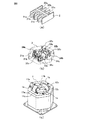
以下、図面を参照して、本発明に係る三相ACリアクトルについて説明する。図3に本発明の実施例に係る三相ACリアクトル10の斜視図を示し、図4に本発明の実施例に係る三相ACリアクトルを構成する三相のコイルの平面図を示す。本発明の実施例に係る三相ACリアクトル10は、三相の各コイル(1a,1b,1c)と、入出力端子台2と、外部接続位置変換部3と、を有する。1は、三相の各コイル(1a,1b,1c)を格納した筐体である。
Hereinafter, a three-phase AC reactor according to the present invention will be described with reference to the drawings. FIG. 3 shows a perspective view of a three-
図4に示すように、本発明の実施例に係る三相ACリアクトルにおいては、三相の各コイル(1a,1b,1c)は、それぞれが平行かつ直線的な配置関係(並置)とはなっていない。図5(c)に、本発明の実施例に係る三相ACリアクトルを構成する三相の各コイルの斜視図を示す。三相の各相のコイル(1a,1b,1c)は、筐体1の内部に設けられている。第1コイル1aは、第1の出力側コイルエンド11a、及び第1の入力側コイルエンド12aを備えている。第2コイル1bは、第2の出力側コイルエンド11b、及び第2の入力側コイルエンド12bを備えている。第3コイル1cは、第3の出力側コイルエンド11c、及び第3の入力側コイルエンド12cを備えている。さらに各コイルエンドの端部は略同一の高さとなるように構成されている。ここで、例えば、第1コイル1aをR相コイルとし、第2コイル1bをS相コイルとし、第3コイル1cをT相コイルとしてもよい。また、「コイルエンド」とは、コイルの端部をいう。
As shown in FIG. 4, in the three-phase AC reactor according to the embodiment of the present invention, the three-phase coils (1a, 1b, 1c) are in a parallel and linear arrangement relationship (parallel arrangement). Not. FIG. 5C is a perspective view of three-phase coils constituting the three-phase AC reactor according to the embodiment of the present invention. The three-phase coils (1 a, 1 b, 1 c) are provided inside the
図3に示すように、入出力端子台2は、入出力部(21a,21b,21c,22a,22b,22c)が平行かつ直線的な配置関係(並置)にある。即ち、第1の出力端子21a、第2の出力端子21b、及び第3の出力端子21cが直線上に配置され、第1の入力端子22a、第2の入力端子22b、及び第3の入力端子22cが直線上に配置されており、かつ2つの直線は平行かつ直線的な配置関係(並置)にある。ここでは、このような配置を「並置」と呼ぶ。
As shown in FIG. 3, the input /
図5(a)に、本発明の実施例に係る三相ACリアクトルを構成する入出力端子台2の斜視図を示す。後述するように、第1の出力端子21aは、バスバー31aを介して第1コイル1aの第1の出力側コイルエンド11aと電気的に接続される。第1の入力端子22aは、バスバー32aを介して第1コイル1aの第1の入力側コイルエンド12aと電気的に接続される。第2の出力端子21bは、バスバー31bを介して第2コイル1bの第2の出力側コイルエンド11bと電気的に接続される。第2の入力端子22bは、バスバー32bを介して第2コイル1bの第2の入力側コイルエンド12bと電気的に接続される。第3の出力端子21cは、バスバー31cを介して第3コイル1cの第3の出力側コイルエンド11cと電気的に接続される。第3の入力端子22cは、バスバー32cを介して第3コイル1cの第3の入力側コイルエンド12cと電気的に接続される。
FIG. 5A is a perspective view of the input /
図5(b)に本発明の実施例に係る三相ACリアクトルを構成する外部接続位置変換部の斜視図を示す。外部接続位置変換部3は、三相の各コイル(1a,1b,1c)のコイルエンド(11a,11b,11c,12a,12b,12c)と入出力端子台2の間に設けられ、コイルエンドと入出力端子台2を接続する。外部接続位置変換部3は、第1の出力端子用バスバー31a、第1の入力端子用バスバー32a、第2の出力端子用バスバー31b、第2の入力端子用バスバー32b、第3の出力端子用バスバー31c、第3の入力端子用バスバー32cを備え、これらを樹脂等にモールドした構造を有する。第1の出力端子用バスバー31aは、第1コイル1a側の端子33a及び他方の端子が水平面に対して垂直方向に形成され、両端子の間の部分が水平方向に形成されている。他のバスバーも同様の構造を有する。
FIG. 5B is a perspective view of the external connection position conversion unit constituting the three-phase AC reactor according to the embodiment of the present invention. The external
第1の出力端子用バスバー31aの第1コイル1a側の端子33aは、第1コイル1aの第1の出力側コイルエンド11aと電気的に接続される。第1の入力端子用バスバー32aの第1コイル1a側の端子34aは、第1コイル1aの第1の入力側コイルエンド12aと電気的に接続される。第2の出力端子用バスバー31bの第2コイル1b側の端子33bは、第2コイル1bの第2の出力側コイルエンド11bと電気的に接続される。第2の入力端子用バスバー32bの第2コイル1b側の端子34bは、第2コイル1bの第2の入力側コイルエンド12bと電気的に接続される。第3の出力端子用バスバー31cの第3コイル1c側の端子33cは、第3コイル1cの第3の出力側コイルエンド11cと電気的に接続される。第3の入力端子用バスバー32cの第3コイル1c側の端子34cは、第3コイル1cの第3の入力側コイルエンド12cと電気的に接続される。
The terminal 33a on the
第1の出力端子用バスバー31aの入出力端子台2側の端子は、第1の出力端子21aと電気的に接続される。第1の入力端子用バスバー32aの入出力端子台2側の端子は、第1の入力端子22aと電気的に接続される。第2の出力端子用バスバー31bの入出力端子台2側の端子は、第2の出力端子21bと電気的に接続される。第2の入力端子用バスバー32bの入出力端子台2側の端子は、第2の入力端子22bと電気的に接続される。第3の出力端子用バスバー31cの入出力端子台2側の端子は、第3の出力端子21cと電気的に接続される。第3の入力端子用バスバー32cの入出力端子台2側の端子は、第3の入力端子22cと電気的に接続される。
The terminal on the input /
図5(a)〜(c)に示した本発明の実施例に係る三相ACリアクトルを構成する入力端子台2、外部接続位置変換部3、及び三相の各コイル(1a,1b,1c)を接続した状態は図3の斜視図のようになる。外部接続位置変換部3は、コイルエンド及び入出力端子台2の接続部と脱着可能な構造を有することが好ましい。
The
上記の実施例においては、外部接続位置変換部を構成するバスバーの一部が他のバスバーと交差する形状を有する例について示した。しかしながら、このような例には限られず、外部接続位置変換部を構成するバスバーの一部が他のバスバーと交差しない形状を有するようにしてもよい。図6(a)は、本発明の実施例に係る外部接続位置変換部3を構成する、交差しない形状を有するバスバー31の平面図であり、図6(b)はバスバー31をモールドするモールド部4の平面図である。
In the above-described embodiment, an example in which a part of the bus bar constituting the external connection position conversion unit has a shape intersecting with another bus bar is shown. However, the present invention is not limited to such an example, and a part of the bus bar that constitutes the external connection position conversion unit may have a shape that does not intersect with other bus bars. FIG. 6A is a plan view of the
外部接続位置変換部3を構成するバスバー31は、第1の出力端子用バスバー301a、第1の入力端子用バスバー302a、第2の出力端子用バスバー301b、第2の入力端子用バスバー302b、第3の出力端子用バスバー301c、第3の入力端子用バスバー302cを備え、これらを樹脂等にモールドした構造を有する。第1の出力端子用バスバー301aは、第1コイル1a側の端子303a及び他方の端子が水平面に対して垂直方向に形成され、両端子の間の部分が水平方向に形成されている。他のバスバーも同様の構造を有する。第1〜第3の出力端子用バスバー301a,301b,301cにおいて、第1〜第3コイル1a,1b,1c側の端子303a,303b,303cが第1〜第3コイル1a,1b,1cの出力側のコイルエンドと接続し、他方の端子が入出力端子台2と接続する。また、第1〜第3の入力端子用バスバー302a,302b,302cにおいて、第1〜第3コイル1a,1b,1c側の端子304a,304b,304cが第1〜第3コイル1a,1b,1cの入力側のコイルエンドと接続し、他方の端子が入出力端子台2と接続する。
The
モールド部41は、複数の突出口(41a〜41c,42a〜42c,43a〜43c,44a〜44c)を備えている。41aは、端子台金属部の挿入口または、バスバー301aの突出口(R相出力側)である。41bは、端子台金属部の挿入口または、バスバー301bの突出口(S相出力側)である。41cは、端子台金属部の挿入口または、バスバー301cの突出口(T相出力側)である。42aは、端子台金属部の挿入口または、バスバー302aの突出口(R相入力側)である。42bは、端子台金属部の挿入口または、バスバー302bの突出口(S相入力側)である。42cは、端子台金属部の挿入口または、バスバー302cの突出口(S相入力側)である。
The
43aは、コイルエンドの挿入口または、バスバー301aの突出口(R相出力側)である。43bは、コイルエンドの挿入口または、バスバー301bの突出口(S相出力側)である。43cは、コイルエンドの挿入口または、バスバー301cの突出口(T相出力側)である。44aは、コイルエンドの挿入口または、バスバー302aの突出口(R相入力側)である。44bは、コイルエンドの挿入口または、バスバー302bの突出口(S相入力側)である。44cは、コイルエンドの挿入口または、バスバー302cの突出口(T相入力側)である。
43a is a coil end insertion port or a protruding port (R-phase output side) of the
バスバーの端子の形状は、種々の構成とすることができる。例えば、コネクタのような圧接による場合は、コイルエンド及び入出力端子台の端子のうちの少なくとも一方がバスバーと脱着可能な構造とすることができる。この場合、モールド部に端子の挿入口を備えることが好ましい。また、ネジ止めによる場合は、バスバーとコイルの終端部及び入出力端子台の端子のうちの少なくとも一方をネジ止め可能な構造とすることができる。 The shape of the terminal of the bus bar can be various. For example, in the case of pressure contact such as a connector, a structure in which at least one of the coil end and the terminal of the input / output terminal block is detachable from the bus bar can be employed. In this case, it is preferable to provide a terminal insertion port in the mold part. In the case of screwing, at least one of the bus bar, the terminal end of the coil, and the terminal of the input / output terminal block can be screwed.
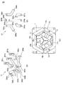
次に、本発明の実施例に係る外部接続位置変換部を構成する、交差しない形状を有するバスバーとコイルエンドとの接続について説明する。図7(a)及び図7(b)は、本発明の実施例に係る外部接続位置変換部を構成する、交差しない形状を有するバスバーの斜視図及び平面図であり、図7(c)は三相ACリアクトルを構成する三相のコイルの平面図である。第1コイル(例えば、R相コイル)1aの出力端子13aは、第1の出力端子用バスバー301aの第1コイル1a側の端子303aと接続する。第2コイル(例えば、S相コイル)1bの出力端子13bは、第2の出力端子用バスバー301bの第2コイル1b側の端子303bと接続する。第3コイル(例えば、T相コイル)1cの出力端子13cは、第3の出力端子用バスバー301cの第3コイル1c側の端子303cと接続する。第1コイル(例えば、R相コイル)1aの入力端子14aは、第1の入力端子用バスバー302aの第1コイル1a側の端子304aと接続する。第2コイル(例えば、S相コイル)1bの入力端子14bは、第2の入力端子用バスバー302bの第2コイル1b側の端子304bと接続する。第3コイル(例えば、T相コイル)1cの入力端子14cは、第3の入力端子用バスバー302cの第3コイル1c側の端子304cと接続する。各バスバーが重ならない構成を備えることによって、各相のバスバー同士の絶縁距離が容易に確保可能、かつ、外部接続位置変換部の高さを最小にできるため、外部接続位置変換部の小型化を実現することができる。外部接続位置変換部の樹脂によるモールド化は必須ではないが、樹脂によるモールド化を行えば絶縁距離の確保がより容易になり、より小型化ができる。
Next, the connection between the bus bar and the coil end, which form the external connection position conversion unit according to the embodiment of the present invention and has a shape that does not intersect, will be described. FIGS. 7A and 7B are a perspective view and a plan view of a bus bar having a non-intersecting shape constituting the external connection position conversion unit according to the embodiment of the present invention, and FIG. It is a top view of the three-phase coil which comprises a three-phase AC reactor. The
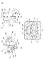
次に、本発明の実施例に係る外部接続位置変換部を構成する、交差する形状を有するバスバーとコイルエンドとの接続について説明する。図8(a)及び図8(b)は、本発明の実施例に係る外部接続位置変換部3を構成する、交差する形状を有するバスバー32の斜視図及び平面図であり、図8(c)は三相ACリアクトルを構成する三相のコイルの平面図である。第1コイル(例えば、R相コイル)1aの出力側コイルエンド11aは、第1の出力端子用バスバー31aの第1コイル1a側の端子33aと接続する。第2コイル(例えば、S相コイル)1bの出力側コイルエンド11bは、第2の出力端子用バスバー31bの第2コイル1b側の端子33bと接続する。第3コイル(例えば、T相コイル)1cの出力側コイルエンド11cは、第3の出力端子用バスバー31cの第3コイル1c側の端子33cと接続する。第1コイル(例えば、R相コイル)1aの入力側コイルエンド12aは、第1の入力端子用バスバー32aの第1コイル1a側の端子34aと接続する。第2コイル(例えば、S相コイル)1bの入力側コイルエンド12bは、第2の入力端子用バスバー32bの第2コイル1b側の端子34bと接続する。第3コイル(例えば、T相コイル)1cの入力側コイルエンド12cは、第3の入力端子用バスバー32cの第3コイル1c側の端子34cと接続する。図8(a)及び図8(b)に示した例では、バスバー31aと31bの一部が重なり、バスバー31bと32aの一部が重なっている。バスバーの一部が他のバスバーと重なる構成を有することにより、コイルと接続する際、コイルエンドの位置を移動させることなく、そのまま入出力端子側に出すことが可能となる。即ち、コイルエンドの位置は通常はコイルの両端部に配置されているが、バスバー同士の一部が重なる構成とすることにより、このコイルエンドの位置を移動させる必要がなくなる。これに対して、バスバー同士が重ならない構成をとる場合は、図7(c)に示すように、少なくとも一部のコイルエンドの位置をコイルの両端部から中央部へ移動させる必要が生じる。なお、上記の実施例においては、バスバー31aと31bの一部が重なり、バスバー31bと32aの一部が重なる例を示したが、バスバーが重なる位置は上記のような例には限られず、他のバスバーの一部が重なるようにしてもよい。
Next, the connection between the bus bar having the intersecting shape and the coil end constituting the external connection position conversion unit according to the embodiment of the present invention will be described. FIGS. 8A and 8B are a perspective view and a plan view of a
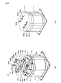
図9(a)〜(c)に、本発明の実施例に係る三相ACリアクトルを構成する三相のコイル、外部接続位置変換部、及び入出力端子台の平面図を示す。また、図10(a)及び(b)に、本発明の実施例に係る三相ACリアクトルを構成する三相のコイル及び外部接続位置変換部の組み立て前後の斜視図を示す。図9(a)に示すように、三相ACリアクトルを構成する第1コイル(R相コイル)1aのR相の出力端子13a、第2コイル(S相コイル)1bのS相の出力端子13b、及び第3コイル(T相コイル)1cのT相の出力端子13cは、直線状に配置(並置)されていない。同様に、第1コイル(R相コイル)1aのR相の入力端子14a、第2コイル(S相コイル)1bのS相の入力端子14b、及び第3コイル(T相コイル)1cのT相の入力端子14cも直線状に配置(並置)されていない。そのため、各相のコイル(1a,1b,1c)と外部機器とを接続する場合、外部機器の接続用端子の位置を各相のコイルの入出力端子の位置に合わせる必要があり、接続を容易に行うことができないという問題があった。
9A to 9C are plan views of a three-phase coil, an external connection position conversion unit, and an input / output terminal block that constitute a three-phase AC reactor according to an embodiment of the present invention. FIGS. 10A and 10B are perspective views before and after assembling the three-phase coil and the external connection position converting portion that constitute the three-phase AC reactor according to the embodiment of the present invention. As shown in FIG. 9A, the R-
これに対して本発明の実施例に係る三相ACリアクトルにおいては、三相ACリアクトルの各相のコイル(1a,1b,1c)と入出力端子台2との間に外部接続位置変換部3を設けることにより、三相ACリアクトルの各相のコイルと外部機器との接続を容易にしている。
On the other hand, in the three-phase AC reactor according to the embodiment of the present invention, the external connection
即ち、図10(a)に示すように、R相の出力端子13a、S相の出力端子13b、及びT相の出力端子13cは、バスバー301aの第1コイル1a側の端子303a、バスバー301bの第2コイル1b側の端子303b、及びバスバー301cの第3コイル1c側の端子303cに、それぞれ接続される。そして、バスバー301a,301b,301cの第1〜第3コイル1a〜1c側の端子303a,303b,303cとは反対側(入出力端子台側)の端子が直線上に配置される。同様に、R相の入力端子14a、S相の入力端子14b、及びT相の入力端子14cは、バスバー302aの第1コイル1a側の端子304a、バスバー302bの第2コイル1b側の端子304b、及びバスバー302cの第3コイル1c側の端子304cに、それぞれ接続される。そして、バスバー302a,302b,302cの第1〜第3コイル1a〜1c側の端子304a,304b,304cとは反対側(入出力端子台側)の端子が直線上に配置される。その結果、外部接続位置変換部3のバスバーの端子が並置されることになり、三相ACリアクトルの各相のコイルと外部機器との接続を容易に行うことができる。
That is, as shown in FIG. 10A, the R-
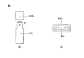
次に、外部接続位置変換部とコイルエンドとの接続方法について、図11(a)及び(b)を用いて説明する。図11(a)は、本発明の実施例に係る外部接続位置変換部3のコイルエンド挿入口とコイルエンドの平面図であり、図11(b)は、その断面図である。例えば、図11(a)に示すように、コイルエンドである第3コイル(T相コイル)1cの入力端子14cを矢印の向きに、コイルエンド挿入口である第3の入力端子用バスバー302cの第3コイル1c側の端子304cに挿入することにより、コイルエンドとバスバーとを接続することができる。
Next, a method for connecting the external connection position conversion unit and the coil end will be described with reference to FIGS. 11 (a) and 11 (b). FIG. 11A is a plan view of the coil end insertion port and the coil end of the external connection
コイルに外部接続位置変換部3を接続すると、図10(b)に示すように、バスバー301a、301b、及び301cの他方の端子が直線上に配置(並置)されることとなる。その結果、図9(c)に示すように、バスバー301a、301b、及び301cの各端子と、入出力端子台2のR相用の第1の出力端子21a、S相用の第2の出力端子21b、及びT相用の第3の出力端子21cとの接続を容易に行うことができる。
When the external connection
同様に、図10(a)に示すように、R相の入力端子14a、S相の入力端子14b、及びT相の入力端子14cは、バスバー302aの第1コイル1a側の端子304a、バスバー302bの第2コイル1b側の端子304b、及びバスバー302cの第3コイル1c側の端子304cに、それぞれ接続される。
Similarly, as shown in FIG. 10A, an R-
コイルに外部接続位置変換部3を接続すると、図10(b)に示すように、バスバー302a、302b、及び302cの他方の端子が直線上に配置(並置)されることとなる。その結果、図9(c)に示すように、バスバー302a、302b、及び302cの各端子と、入出力端子台2のR相用の第1の入力端子22a、S相用の第2の入力端子22b、及びT相用の第3の入力端子22cとの接続を容易に行うことができる。
When the external connection
次に、外部接続位置変換部3と入出力端子台2との接続方法について説明する。図12(a)及び(b)に本発明の実施例に係る外部接続位置変換部と入出力端子台の接続をネジ止めによって行う場合の例を示す。図12(a)はネジ止めする前の状態を示し、図12(b)はネジ止めした後の状態を示す。例えば、バスバー301aに設けた孔の位置と、入出力端子台2の第1の出力端子21aに設けた孔の位置を合わせて、ネジ51aでネジ止めすることができる。同様にバスバー301bに設けた孔の位置と、入出力端子台2の第2の出力端子21bに設けた孔の位置を合わせて、ネジ51bでネジ止めすることができる。同様にバスバー301cに設けた孔の位置と、入出力端子台2の第3の出力端子21cに設けた孔の位置を合わせて、ネジ51cでネジ止めすることができる。入力側の端子についても同様に、入力端子用バスバー302a,302b,302cに設けた孔の位置と、入出力端子台2の第1〜第3の入力端子221,22b,22cに設けた孔の位置を合わせて、ネジ52a,52b,52cでそれぞれネジ止めすることができる。
Next, a method for connecting the external connection
なお、コイルエンドと外部接続位置変換部3の接続および外部接続位置変換部3と入出力端子台の接続は、ネジ止め、コネクタ等を設けた圧接いずれでもよく、コイルエンドと外部接続位置変換部3の接続および外部接続位置変換部3と入出力端子台の接続のうち少なくとも一方がコネクタ等を設けた圧接によるものとする。
The connection between the coil end and the external connection
本発明の実施例に係る三相ACリアクトルによれば、非並置型平角線コイルのコイルエンドの位置を外部機器との接続部が並置となる位置に変換出来るため、外部機器との接続配線を容易に行うことが可能になる。 According to the three-phase AC reactor according to the embodiment of the present invention, since the position of the coil end of the non-parallel type rectangular wire coil can be converted into a position where the connection portion with the external device is juxtaposed, the connection wiring with the external device is arranged. It becomes possible to carry out easily.
次に、本発明の実施例に係る三相ACリアクトルの製造方法について説明する。本発明の実施例に係る三相ACリアクトルの製造方法は、上述した実施例に係る三相ACリアクトルを製造する方法であって、コイルエンドに、外部接続位置変換部3のバスバーの三相の各コイル側の端子を挿入し接続する工程と、外部接続位置変換部3の入出力端子台側の端子に、入出力端子台2の入出力端子を挿入し接続する工程と、を有する。
Next, the manufacturing method of the three-phase AC reactor which concerns on the Example of this invention is demonstrated. The manufacturing method of the three-phase AC reactor according to the embodiment of the present invention is a method of manufacturing the three-phase AC reactor according to the above-described embodiment, and the three-phase AC reactor of the external connection
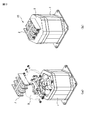
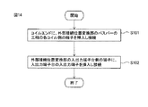
図13に本発明の実施例に係る三相ACリアクトル10の各部を分解表示した図を示す。図13(a)は、三相ACリアクトルに外部接続位置変換部3及び入出力端子台を接続する前の状態を示し、図13(b)は接続した後の状態を示す。図14に、本発明の実施例に係る三相ACリアクトルの製造方法を説明するためのフローチャートを示す。まず、ステップS101において、コイルエンド(11a,12a,11b,12b,11c,12c)に、外部接続位置変換部3のバスバー(31a,32a,31b,32b,31c,32c)の三相の各コイル側の端子(33a,34a,33b,34b,33c,34c)(図10(a)、図11参照)を挿入し接続する。
FIG. 13 is an exploded view of each part of the three-
次に、ステップS102において、外部接続位置変換部3のバスバー(31a,31b,31c,32a,32b,32c)の入出力端子台2側の端子(図13参照)に、入出力端子台2の入出力端子(21a,21b,21c,22a,22b,22c)を挿入し接続する。
Next, in step S102, the input /
以上の説明においては、バスバーと入出力端子台は個別に形成される例を示したが、バスバーと入出力端子台は一体形成されるようにしてもよい。このような構成とすることにより、バスバーと入出力端子台とを接続する工程を簡略化することができる。 In the above description, an example in which the bus bar and the input / output terminal block are individually formed has been described. However, the bus bar and the input / output terminal block may be integrally formed. With such a configuration, the process of connecting the bus bar and the input / output terminal block can be simplified.
本発明の実施例に係る三相ACリアクトルの製造方法によれば、自動化を前提とした非並置型平角線コイルを具備するACリアクトルの製造工程において、外部接続位置変換部に平角線コイルのコイルエンドを挿入するだけで、三相ACリアクトルのコイルエンドと入出力接続部の接続が可能であるため同製造工程を自動化する事が容易となる。 According to the method of manufacturing a three-phase AC reactor according to an embodiment of the present invention, in the AC reactor manufacturing process including a non-parallel type rectangular wire coil on the premise of automation, a coil of a rectangular wire coil is provided in the external connection position conversion unit. By simply inserting the end, it is possible to connect the coil end of the three-phase AC reactor and the input / output connection portion, so that the manufacturing process can be easily automated.
1a 第1コイル
1b 第2コイル
1c 第3コイル
2 入出力端子台
3 外部接続位置変換部
4 モールド部
10 三相ACリアクトル
31、32 バスバー
DESCRIPTION OF
Claims (3)
入出力部が平行かつ直線的な配置関係(並置)にある入出力端子台と、
前記三相の各コイルのコイルエンドと前記入出力端子台の間に、前記コイルエンドと前記入出力端子台を接続する外部接続位置変換部と、
を有することを特徴とする三相ACリアクトル。 Each of the three-phase coils that are not parallel and linear arrangement (parallel),
An input / output terminal block in which the input / output units are in parallel and linear arrangement (parallel);
Between the coil end of each of the three-phase coils and the input / output terminal block, an external connection position conversion unit that connects the coil end and the input / output terminal block;
A three-phase AC reactor characterized by comprising:
前記コイルエンドに、前記外部接続位置変換部のバスバーの前記三相の各コイル側の端子を挿入し接続する工程と、
前記外部接続位置変換部の入出力端子台側の端子に、前記入出力端子台の入出力端子を挿入し接続する工程と、
を有する、三相ACリアクトルの製造方法。 A method for producing a three-phase AC reactor according to claim 1 or 2,
Inserting and connecting the terminals on the three-phase coil side of the bus bar of the external connection position conversion unit to the coil end; and
Inserting and connecting the input / output terminals of the input / output terminal block to the terminals on the input / output terminal block side of the external connection position conversion unit; and
A method for producing a three-phase AC reactor.
Priority Applications (7)
| Application Number | Priority Date | Filing Date | Title |
|---|---|---|---|
| JP2016141678A JP6514151B2 (en) | 2016-07-19 | 2016-07-19 | Three-phase AC reactor provided with an external connection position converter and method of manufacturing the same |
| DE102017115626.7A DE102017115626A1 (en) | 2016-07-19 | 2017-07-12 | Three-phase alternating current reactor with position change unit for external connections and method for their production |
| US15/650,333 US10490336B2 (en) | 2016-07-19 | 2017-07-14 | Three-phase AC reactor having external connection position change unit and manufacturing method thereof |
| CN201720879450.1U CN206907633U (en) | 2016-07-19 | 2017-07-19 | Three-phase AC reactors |
| CN201710591651.6A CN107633945B (en) | 2016-07-19 | 2017-07-19 | Three-phase AC reactor and method for manufacturing same |
| US16/598,212 US10622137B2 (en) | 2016-07-19 | 2019-10-10 | Three-phase AC reactor having external connection position change unit and manufacturing method thereof |
| US16/598,207 US11551854B2 (en) | 2016-07-19 | 2019-10-10 | Method for manufacturing a three-phase AC reactor having external connection position change unit |
Applications Claiming Priority (1)
| Application Number | Priority Date | Filing Date | Title |
|---|---|---|---|
| JP2016141678A JP6514151B2 (en) | 2016-07-19 | 2016-07-19 | Three-phase AC reactor provided with an external connection position converter and method of manufacturing the same |
Publications (2)
| Publication Number | Publication Date |
|---|---|
| JP2018014366A true JP2018014366A (en) | 2018-01-25 |
| JP6514151B2 JP6514151B2 (en) | 2019-05-15 |
Family
ID=60890384
Family Applications (1)
| Application Number | Title | Priority Date | Filing Date |
|---|---|---|---|
| JP2016141678A Active JP6514151B2 (en) | 2016-07-19 | 2016-07-19 | Three-phase AC reactor provided with an external connection position converter and method of manufacturing the same |
Country Status (4)
| Country | Link |
|---|---|
| US (3) | US10490336B2 (en) |
| JP (1) | JP6514151B2 (en) |
| CN (2) | CN206907633U (en) |
| DE (1) | DE102017115626A1 (en) |
Cited By (1)
| Publication number | Priority date | Publication date | Assignee | Title |
|---|---|---|---|---|
| JP2021044365A (en) * | 2019-09-10 | 2021-03-18 | 株式会社タムラ製作所 | Reactor and method for manufacturing the same |
Families Citing this family (5)
| Publication number | Priority date | Publication date | Assignee | Title |
|---|---|---|---|---|
| JP6450739B2 (en) * | 2016-12-22 | 2019-01-09 | ファナック株式会社 | Electromagnetic equipment |
| JP6423902B2 (en) | 2017-02-16 | 2018-11-14 | ファナック株式会社 | Three-phase AC reactor that can reduce magnetic flux leakage |
| JP1590155S (en) * | 2017-03-23 | 2017-11-06 | ||
| JP1590156S (en) * | 2017-03-23 | 2017-11-06 | ||
| JP7376902B2 (en) * | 2019-02-19 | 2023-11-09 | 株式会社アスター | Coil zygote and method for manufacturing the coil zygote |
Citations (10)
| Publication number | Priority date | Publication date | Assignee | Title |
|---|---|---|---|---|
| JPS5362166A (en) * | 1976-11-17 | 1978-06-03 | Tokyo Shibaura Electric Co | Starting reactor |
| CN202487364U (en) * | 2012-03-13 | 2012-10-10 | 北京新特电气有限公司 | Leading-out wire structure of three-phase three-dimensional wound core reactor |
| JP2012256807A (en) * | 2011-06-10 | 2012-12-27 | Seiden Seisakusho:Kk | High frequency transformer |
| US20140002229A1 (en) * | 2011-05-27 | 2014-01-02 | Guangdong Haihong Co., Ltd. | Resin-molded stereo wound-core dry-type amorphous alloy transformer |
| JP2014039037A (en) * | 2012-08-16 | 2014-02-27 | Aeg Power Solutions Bv | Power supply device system including transformer having transformer core with leg arranged in polygon |
| WO2014033830A1 (en) * | 2012-08-28 | 2014-03-06 | 株式会社日立製作所 | Power conversion device |
| WO2014073252A1 (en) * | 2012-11-08 | 2014-05-15 | 株式会社日立産機システム | Reactor device |
| JP2015032718A (en) * | 2013-08-04 | 2015-02-16 | 株式会社タムラ製作所 | Resin mold core and reactor using the same |
| CN104376990A (en) * | 2014-12-15 | 2015-02-25 | 何达江 | Lead structure of triangular iron roll core transformer |
| JP2015122484A (en) * | 2013-11-22 | 2015-07-02 | 株式会社タムラ製作所 | Coil, manufacturing method thereof, and reactor |
Family Cites Families (11)
| Publication number | Priority date | Publication date | Assignee | Title |
|---|---|---|---|---|
| US1553983A (en) | 1919-12-26 | 1925-09-15 | Western Electric Co | Electrical coil |
| US2397009A (en) * | 1941-10-18 | 1946-03-19 | Bendix Aviat Corp | Optical apparatus |
| US4912618A (en) * | 1988-11-04 | 1990-03-27 | Sundstrand Corporation | Variable speed, constant frequency generating system with input transformer |
| US20030206087A1 (en) * | 2002-05-06 | 2003-11-06 | Square D Company | Magnetic system having three-dimensional symmetry for three phase transformers |
| CN2645196Y (en) | 2003-09-28 | 2004-09-29 | 杨京殿 | Iron core current-limiting reactor |
| US7623016B2 (en) * | 2005-06-07 | 2009-11-24 | Mte Corporation | Snap together multiple phase inductor assembly |
| US7768373B2 (en) * | 2008-04-22 | 2010-08-03 | Cramer Coil & Transformer Co., Inc. | Common mode, differential mode three phase inductor |
| JP4717904B2 (en) | 2008-05-22 | 2011-07-06 | 株式会社タムラ製作所 | Reactor |
| JP5288326B2 (en) | 2008-08-11 | 2013-09-11 | 住友電気工業株式会社 | Reactor assembly |
| JPWO2012157053A1 (en) | 2011-05-16 | 2014-07-31 | 株式会社日立製作所 | Reactor device and power converter using the same |
| PL2767990T3 (en) * | 2013-02-18 | 2015-09-30 | Abb Technology Ag | Method for manufacturing a stacked triangular core transformer |
-
2016
- 2016-07-19 JP JP2016141678A patent/JP6514151B2/en active Active
-
2017
- 2017-07-12 DE DE102017115626.7A patent/DE102017115626A1/en active Pending
- 2017-07-14 US US15/650,333 patent/US10490336B2/en active Active
- 2017-07-19 CN CN201720879450.1U patent/CN206907633U/en active Active
- 2017-07-19 CN CN201710591651.6A patent/CN107633945B/en active Active
-
2019
- 2019-10-10 US US16/598,207 patent/US11551854B2/en active Active
- 2019-10-10 US US16/598,212 patent/US10622137B2/en active Active
Patent Citations (10)
| Publication number | Priority date | Publication date | Assignee | Title |
|---|---|---|---|---|
| JPS5362166A (en) * | 1976-11-17 | 1978-06-03 | Tokyo Shibaura Electric Co | Starting reactor |
| US20140002229A1 (en) * | 2011-05-27 | 2014-01-02 | Guangdong Haihong Co., Ltd. | Resin-molded stereo wound-core dry-type amorphous alloy transformer |
| JP2012256807A (en) * | 2011-06-10 | 2012-12-27 | Seiden Seisakusho:Kk | High frequency transformer |
| CN202487364U (en) * | 2012-03-13 | 2012-10-10 | 北京新特电气有限公司 | Leading-out wire structure of three-phase three-dimensional wound core reactor |
| JP2014039037A (en) * | 2012-08-16 | 2014-02-27 | Aeg Power Solutions Bv | Power supply device system including transformer having transformer core with leg arranged in polygon |
| WO2014033830A1 (en) * | 2012-08-28 | 2014-03-06 | 株式会社日立製作所 | Power conversion device |
| WO2014073252A1 (en) * | 2012-11-08 | 2014-05-15 | 株式会社日立産機システム | Reactor device |
| JP2015032718A (en) * | 2013-08-04 | 2015-02-16 | 株式会社タムラ製作所 | Resin mold core and reactor using the same |
| JP2015122484A (en) * | 2013-11-22 | 2015-07-02 | 株式会社タムラ製作所 | Coil, manufacturing method thereof, and reactor |
| CN104376990A (en) * | 2014-12-15 | 2015-02-25 | 何达江 | Lead structure of triangular iron roll core transformer |
Cited By (1)
| Publication number | Priority date | Publication date | Assignee | Title |
|---|---|---|---|---|
| JP2021044365A (en) * | 2019-09-10 | 2021-03-18 | 株式会社タムラ製作所 | Reactor and method for manufacturing the same |
Also Published As
| Publication number | Publication date |
|---|---|
| US10490336B2 (en) | 2019-11-26 |
| US20200043647A1 (en) | 2020-02-06 |
| CN107633945A (en) | 2018-01-26 |
| US20180025830A1 (en) | 2018-01-25 |
| US10622137B2 (en) | 2020-04-14 |
| US11551854B2 (en) | 2023-01-10 |
| US20200043646A1 (en) | 2020-02-06 |
| CN107633945B (en) | 2020-04-03 |
| JP6514151B2 (en) | 2019-05-15 |
| DE102017115626A1 (en) | 2018-01-25 |
| CN206907633U (en) | 2018-01-19 |
Similar Documents
| Publication | Publication Date | Title |
|---|---|---|
| JP6514151B2 (en) | Three-phase AC reactor provided with an external connection position converter and method of manufacturing the same | |
| JP6546140B2 (en) | Three-phase AC reactor easy to connect to input terminal block and method of manufacturing the same | |
| JP6378385B1 (en) | AC reactor with terminal block | |
| US10784037B2 (en) | Reactor having temperature sensor attached to terminal base unit | |
| JP2021040144A (en) | Switch power supply device | |
| US10755850B2 (en) | Three-phase AC reactor having coils directly connected to external device and manufacturing method thereof | |
| JP2019016711A (en) | Reactor having covering portion provided with mechanism engaging with each other | |
| JP5525069B2 (en) | Coil member and stator | |
| JP2017188202A (en) | Terminal block with built-in coil | |
| JP5549467B2 (en) | Inverter device | |
| WO2023130591A1 (en) | Wiring structure | |
| JP2016101018A (en) | Stator of dynamo-electric machine, and dynamo-electric machine including the same | |
| JP2022071589A (en) | Static electromagnetic device and manufacturing method thereof | |
| JP5699492B2 (en) | Electrical equipment connection device | |
| WO2019207723A1 (en) | Power conversion device and power conversion unit | |
| JP2015164146A (en) | inductor component | |
| JP2023074158A (en) | Power conversion device | |
| JP5701171B2 (en) | Manufacturing method of stator for rotating electric machine and stator for rotating electric machine | |
| JP2011228247A (en) | Bushing for electrical apparatus | |
| JP2002186157A (en) | Gas-insulated switchgear | |
| JP2017060252A (en) | Fuse box, fuse unit, and fuse | |
| JP2016115482A (en) | Electric wire connector |
Legal Events
| Date | Code | Title | Description |
|---|---|---|---|
| A977 | Report on retrieval |
Free format text: JAPANESE INTERMEDIATE CODE: A971007 Effective date: 20180727 |
|
| A131 | Notification of reasons for refusal |
Free format text: JAPANESE INTERMEDIATE CODE: A131 Effective date: 20180828 |
|
| A521 | Request for written amendment filed |
Free format text: JAPANESE INTERMEDIATE CODE: A523 Effective date: 20181029 |
|
| A131 | Notification of reasons for refusal |
Free format text: JAPANESE INTERMEDIATE CODE: A131 Effective date: 20181120 |
|
| A521 | Request for written amendment filed |
Free format text: JAPANESE INTERMEDIATE CODE: A523 Effective date: 20190115 |
|
| TRDD | Decision of grant or rejection written | ||
| A01 | Written decision to grant a patent or to grant a registration (utility model) |
Free format text: JAPANESE INTERMEDIATE CODE: A01 Effective date: 20190312 |
|
| A61 | First payment of annual fees (during grant procedure) |
Free format text: JAPANESE INTERMEDIATE CODE: A61 Effective date: 20190411 |
|
| R150 | Certificate of patent or registration of utility model |
Ref document number: 6514151 Country of ref document: JP Free format text: JAPANESE INTERMEDIATE CODE: R150 |