JP2018009875A - Ground fault detector - Google Patents
Ground fault detector Download PDFInfo
- Publication number
- JP2018009875A JP2018009875A JP2016138819A JP2016138819A JP2018009875A JP 2018009875 A JP2018009875 A JP 2018009875A JP 2016138819 A JP2016138819 A JP 2016138819A JP 2016138819 A JP2016138819 A JP 2016138819A JP 2018009875 A JP2018009875 A JP 2018009875A
- Authority
- JP
- Japan
- Prior art keywords
- ground fault
- fault detection
- signal
- pass filter
- power supply
- Prior art date
- Legal status (The legal status is an assumption and is not a legal conclusion. Google has not performed a legal analysis and makes no representation as to the accuracy of the status listed.)
- Pending
Links
Images
Landscapes
- Testing Of Short-Circuits, Discontinuities, Leakage, Or Incorrect Line Connections (AREA)
- Electric Propulsion And Braking For Vehicles (AREA)
Abstract
Description
本発明は、地絡を検知する装置(地絡検知装置)に関する。 The present invention relates to a device for detecting a ground fault (ground fault detection device).
例えば特許文献1は、非地絡回路の地絡検知装置を開示し、その地絡検知装置10は、例えばリチウムイオン電池71を含む非地絡回路70の地絡検知を実行する地絡検出部64だけでなく、例えば電源電圧検出部66も備えている。電源電圧検出部66は、非地絡回路70の電源電圧(リチウムイオン電池71の出力電圧)の検出を実行することができる。特許文献1の地絡検知装置10(地絡検出部64及び電源電圧検出部66)は、電源電圧の両端(具体的には、直流電源であるリチウムイオン電池71の正極側及び負極側の出力部)に検知用信号S_Sigを重畳することによって、非地絡回路70の地絡検知及び電源電圧検出を同時に実行可能であるので、地絡検出部64及び電源電圧検出部66は、小型化又は共用化することができる。
For example,
しかしながら、本発明者らは、特許文献1の地絡検知装置10において、地絡検出部64の入力信号内のノイズを認識した。具体的には、本発明者らは、リチウムイオン電池71の直流電源をインバータ73に接続される駆動用電動機(モータ)に投入する時によるリチウムイオン電池71の正極側及び負極側の出力部の電圧変動や、車両走行時におけるモータの駆動又は回生などによるリチウムイオン電池71の正極側及び負極側の出力部の電圧変動によって、地絡信号検知回路53の出力信号にノイズが重複し、出力信号が最大値又は最小値で張り付くことに起因して、地絡を検知するための地絡抵抗値を正確に算出することができなくなり、地絡の検知精度の低下を認識した。
However, the present inventors have recognized noise in the input signal of the ground fault detection unit 64 in the ground fault detection device 10 of
また、特許文献1の地絡検知装置10において、地絡検知信号内のノイズを認識した。具体的には、本発明者らは、検知用信号を発生させる検知用信号発振器50の電源と地絡検知信号を処理する反転アンプ25,35及び地絡信号検知回路53の電源とが異なるため、各電源の変動に起因する地絡の検知精度の低下を認識した。
Moreover, in the ground fault detection apparatus 10 of
本発明の目的は、地絡の検知精度を向上可能な地絡検知装置を提供することである。 The objective of this invention is providing the ground fault detection apparatus which can improve the detection precision of a ground fault.
以下に、本発明の概要を容易に理解するために、本発明に従う態様を例示する。 In the following, in order to easily understand the outline of the present invention, embodiments according to the present invention will be exemplified.
第1の態様において、地絡検知装置は、
固定の周波数を有する交流信号である地絡検知用信号を発生させる信号発生部と、
前記地絡検知用信号を地絡検知対象である直流電源の両端にそれぞれ対応する第1の電源線路と第2の電源線路とに供給する信号供給部と、
前記第1の電源線路と前記第2の電源線路とから得られた第1及び第2の地絡検知用信号をそれぞれ含む第1及び第2の被検知信号を信号処理する信号処理部と、
前記信号処理部の第1及び第2の出力信号を加算し、単一の加算信号を生成する加算回路と、
前記加算回路によって生成された前記単一の加算信号から前記固定の周波数に相当する周波数成分を前記地絡検知用信号として抽出するバントパスフィルタと、
前記バントパスフィルタから出力される前記地絡検知用信号に基づいて前記直流電源の地絡を検知する地絡検知部と、
を備え、
前記地絡検知部は、前記バントパスフィルタでフィルタ処理された後の前記地絡検知用信号の値が下限閾値よりも小さい又は上限閾値よりも大きい時に、前記バンドパスフィルタでは除去することができないノイズ(バンドパスフィルタ応答ノイズ)であって前記第1の電源線路のインピーダンスと前記第2の電源線路のインピーダンスとの差が変化することにより発生する前記ノイズ(バンドパスフィルタ応答ノイズ)が前記地絡検知用信号に重畳していると判断し、前記地絡の検知を無効化する。
In the first aspect, the ground fault detection device comprises:
A signal generator for generating a ground fault detection signal which is an AC signal having a fixed frequency;
A signal supply unit that supplies the ground fault detection signal to a first power line and a second power line respectively corresponding to both ends of a DC power source that is a ground fault detection target;
A signal processing unit that performs signal processing on the first and second detected signals respectively including the first and second ground fault detection signals obtained from the first power supply line and the second power supply line;
An adding circuit for adding the first and second output signals of the signal processing unit to generate a single added signal;
A band pass filter that extracts a frequency component corresponding to the fixed frequency from the single addition signal generated by the addition circuit as the ground fault detection signal;
A ground fault detection unit that detects a ground fault of the DC power supply based on the ground fault detection signal output from the band pass filter;
With
The ground fault detection unit cannot be removed by the band pass filter when the value of the ground fault detection signal after being filtered by the band pass filter is smaller than a lower threshold or larger than an upper threshold. The noise (bandpass filter response noise) generated when the difference between the impedance of the first power supply line and the impedance of the second power supply line changes is the ground (bandpass filter response noise). It judges that it has superimposed on the signal for a fault detection, and invalidates the detection of the ground fault.
第1の態様では、地絡検知対象である直流電源の両端にそれぞれ対応する第1の電源線路と第2の電源線路とから得られた第1及び第2の地絡検知用信号をそれぞれ含む第1及び第2の被検知信号を加算回路によって加算し、加算信号を生成し、その加算信号から、バンドパスフィルタによって固定の周波数を有する地絡検知用信号を抽出することができる。 In the first aspect, the first and second ground fault detection signals respectively obtained from the first power source line and the second power source line respectively corresponding to both ends of the DC power source that is a ground fault detection target are included. The first and second detected signals can be added by an adder circuit to generate an added signal, and a ground fault detection signal having a fixed frequency can be extracted from the added signal by a bandpass filter.
その後、地絡検知部は、バンドパスフィルタでフィルタ処理された後の地絡検知用信号の値が下限閾値よりも小さい又は上限閾値よりも大きい時に、バンドパスフィルタでは除去することができないノイズ(バンドパスフィルタ応答ノイズ)であって第1の電源線路のインピーダンスと第2の電源線路のインピーダンスとの差が変化することにより発生するノイズ(バンドパスフィルタ応答ノイズ)が地絡検知用信号に重畳していると判断し、地絡の検知を無効化することができる。 Thereafter, when the value of the ground fault detection signal after being filtered by the band pass filter is smaller than the lower limit threshold or larger than the upper limit threshold, the ground fault detection unit is a noise that cannot be removed by the band pass filter ( Bandpass filter response noise), which is generated when the difference between the impedance of the first power supply line and the impedance of the second power supply line is changed (bandpass filter response noise) is superimposed on the ground fault detection signal. It is possible to invalidate the detection of the ground fault.
即ち、地絡検知部はノイズが重畳している地絡検知信号に基づく地絡検知を実行することがないので、地絡の検知精度は向上する。 That is, since the ground fault detection unit does not execute ground fault detection based on the ground fault detection signal on which noise is superimposed, the ground fault detection accuracy is improved.
第1の態様に従属する第2の態様において、前記バントパスフィルタは、ハイパスフィルタと、ローパスフィルタとの組み合わせから構成され、
前記バントパスフィルタは、前記加算回路からの前記単一の加算信号を前記ハイパスフィルタでフィルタ処理し、前記ハイパスフィルタでフィルタ処理された前記単一の加算信号を前記ローパスフィルタによってフィルタ処理することで前記地絡検知用信号を抽出する。
In a second aspect subordinate to the first aspect, the bunt pass filter is composed of a combination of a high pass filter and a low pass filter,
The band pass filter is configured to filter the single addition signal from the adder circuit with the high pass filter and filter the single addition signal filtered with the high pass filter with the low pass filter. The ground fault detection signal is extracted.
第2の態様では、加算信号をハイパスフィルタによって地絡検知用信号の固定の周波数よりも高い周波数以上の周波数成分を通過させ、ローパスフィルタによって地絡検知用信号の固定の周波数よりも低い周波数以下の周波数成分を通過させることができる。 In the second aspect, the addition signal is passed through a frequency component higher than the fixed frequency of the ground fault detection signal by the high pass filter, and is lower than the frequency lower than the fixed frequency of the ground fault detection signal by the low pass filter. Can be passed.
言い換えれば、加算信号の固定の周波数に相当する周波数成分を地絡検知用信号として抽出し、それ以外の周波数成分(ノイズ)を遮断することができる。 In other words, a frequency component corresponding to a fixed frequency of the addition signal can be extracted as a ground fault detection signal, and other frequency components (noise) can be blocked.
当業者は、例示した本発明に従う態様が、本発明の精神を逸脱することなく、さらに変更され得ることを容易に理解できるであろう。 Those skilled in the art will readily understand that the illustrated embodiments according to the present invention can be further modified without departing from the spirit of the present invention.
以下に説明する最良の実施形態は、本発明を容易に理解するために用いられている。従って、当業者は、本発明が、以下に説明される実施形態によって不当に限定されないことを留意すべきである。 The best mode described below is used to easily understand the present invention. Accordingly, those skilled in the art should note that the present invention is not unduly limited by the embodiments described below.
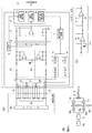
図1(A)は、本発明に従う地絡検知装置を含む、地絡検知装置システムの構成例を示す。図1(A)に示されるように、地絡検知装置Aは、1例として、バッテリECU(Electronic Control Unit)であり、地絡検知対象である直流電源として、例えばバッテリBの地絡を検知する。図1(A)の地絡検知装置システムは、地絡検知装置Aと、例えば自動車等の車両の本体に備えられたバッテリB(車両バッテリ)と、バッテリBの正極側のプラス端子及び負極側のマイナス端子にそれぞれ対応する第1の電源線路Sp及び第2の電源線路Sn(一対の高圧電源線路)と、を備えている。図1(A)において、地絡検知装置システムは、バッテリBを構成する複数の電池(セル)に対応する、第1の電源線路Sp及び第2の電源線路Sn以外の複数の電源線路を有することができる。 FIG. 1A shows a configuration example of a ground fault detection device system including a ground fault detection device according to the present invention. As shown in FIG. 1A, the ground fault detection device A is a battery ECU (Electronic Control Unit) as an example, and detects, for example, a ground fault of the battery B as a DC power source that is a ground fault detection target. To do. 1A includes a ground fault detection device A, a battery B (vehicle battery) provided in a main body of a vehicle such as an automobile, a positive terminal on the positive side of the battery B, and a negative side. The first power supply line Sp and the second power supply line Sn (a pair of high-voltage power supply lines) respectively corresponding to the negative terminals of In FIG. 1A, the ground fault detection apparatus system has a plurality of power supply lines other than the first power supply line Sp and the second power supply line Sn corresponding to the plurality of batteries (cells) constituting the battery B. be able to.
図1(A)の地絡検知装置Aは、例えば基準信号発生器4cで構成される信号発生部と、例えば電圧変換回路5並びに結合回路6p及び結合回路6nで構成される信号供給部と、例えば分圧回路1p及び分圧回路1nで構成される信号処理部と、地絡検知部4aと、加算回路2と、バンドパスフィルタ3(BPF)と、を備えている。地絡検知装置Aは、1例として、例えば差動増幅器7を介してバッテリBの両端電圧(総電圧)を検出する電圧検出部4bを更に備えることができる。加えて、地絡検知装置A又は地絡検知装置Aの演算処理部4、或いは、地絡検知装置Aの上位制御系は、1例として、例えば検出回路S1,S2,・・・,SMを介してセル電圧及び/又はセル電流等で少なくとも1つのセル(好ましくは、すべてのセル)の状態を監視することができる。
A ground fault detection apparatus A in FIG. 1A includes, for example, a signal generation unit configured by a
図1(A)において、信号発生部は、固定の周波数を有する交流信号である地絡検知用信号(1種類の地絡検知用信号)を発生させ、典型的には、基準信号発生器4cは、1例として、例えば50[%]のDuty比を有する例えば矩形波からなる地絡検知用信号(基準信号)を発生させる。例えば方形波発生器である基準信号発生器4cによって生成される例えば矩形波又は地絡検知用信号(基準信号)の振幅は、基準信号発生器4cの電源電圧(例えば図1(B)の電源Eの電源電圧参照)よりも低い電圧である。
In FIG. 1A, the signal generator generates a ground fault detection signal (one type of ground fault detection signal) which is an AC signal having a fixed frequency, and typically, the
図1(A)において、信号供給部は、地絡検知用信号を地絡検知対象である直流電源(例えばバッテリB)の両端にそれぞれ対応する第1及び第2の電源線路Sp,Snに供給する。具体的には、電圧変換回路5は、1例として、基準信号発生器4cの電源電圧よりも低い電圧である振幅を有する地絡検知用信号を、電圧変換回路5の電源電圧(例えば図1(B)の電源Eの電源電圧参照)に増幅又は電圧変換する。電圧変換回路5は、電圧変換後の地絡検知用信号を一対の結合回路6p,6nに出力する。結合回路6p及び結合回路6nの各々は、各々が抵抗器とコンデンサとからなる並列回路である複数の単位中継回路と、抵抗器と、からなる直並列回路である。結合回路6pの一端及び他端は、それぞれ電圧変換回路5及び第1の電源線路Spの接続点(入力端Kp)に接続される一方、結合回路6nの一端及び他端は、それぞれ電圧変換回路5及び第2の電源線路Snの接続点(入力端Kn)に接続されている。
In FIG. 1A, the signal supply unit supplies a ground fault detection signal to first and second power supply lines Sp and Sn corresponding to both ends of a DC power source (for example, battery B) that is a ground fault detection target. To do. Specifically, as an example, the
地絡検知用信号が第1の電源線路Spに供給されるので、第1の電源線路Spは、第1の伝送線路と呼ぶこともできる。同様に、地絡検知用信号が第2の電源線路Snに供給されるので、第2の電源線路Snは、第2の伝送線路と呼ぶこともできる。 Since the ground fault detection signal is supplied to the first power supply line Sp, the first power supply line Sp can also be referred to as a first transmission line. Similarly, since the ground fault detection signal is supplied to the second power supply line Sn, the second power supply line Sn can also be called a second transmission line.
図1(A)において、信号処理部は、直流電源(例えばバッテリB)の両端にそれぞれ対応する第1の電源線路Sp(第1の伝送線路)と第2の電源線路Sn(第2の伝送線路)とから得られた第1及び第2の地絡検知用信号をそれぞれ含む第1及び第2の被検知信号を信号処理する。具体的には、分圧回路1p,1nの各々は、1例として、複数の抵抗器と、オペアンプと、コンデンサと、からなる反転増幅器である。分圧回路1pの入力(オペアンプの正の入力)は、入力端Kp及び第1の電源線路Spを介して、バッテリBの正極側の出力部に接続されている。分圧回路1nの入力(オペアンプの正の入力)は、入力端Kn及び第2の電源線路Snを介して、バッテリBの負極側の出力部に接続されている。
In FIG. 1A, the signal processing unit includes a first power supply line Sp (first transmission line) and a second power supply line Sn (second transmission) corresponding to both ends of a DC power supply (for example, battery B). The first and second detected signals including the first and second ground fault detection signals obtained from the line) are processed. Specifically, each of the
分圧回路1p,1nの各々において、オペアンプの入力抵抗が複数の抵抗器の直列接回路で構成され、第1の電源線路Sp又は第2の電源線路Snから入力される入力信号(第1又は第2の被検知信号)を分圧すると共にバッファリングして出力することができる。加えて、オペアンプの帰還抵抗に並列にコンデンサが挿入されているので、オペアンプは、ローパスフィルタとしても機能する。ここで、ローパスフィルタは、地絡検知部4aのA/D変換部分及び/又は電圧検出部4bのA/D変換部分のサンプリング周波数(A/D変換周期の逆数)の半分以上の周波数成分を除去するように構成されている。
In each of the
分圧回路1p,1nの各々において、オペアンプの負の入力は、オフセット電圧、具体的には、分圧回路1p,1nの電源電圧(例えば図1(B)の電源Eの電源電圧参照)の例えば半分に接続されている。
In each of the
図1(A)において、信号抽出部(加算回路2及びバントパスフィルタ3)は、信号処理部の第1及び第2の出力信号(第1及び第2の被検知信号)を加算し、単一の加算信号から、地絡検知用信号の固定の周波数に適合されたアナログフィルタで構成されるバントパスフィルタ3で、加算信号の固定の周波数に相当する周波数成分を地絡検知用信号(単一の地絡検知用信号)として抽出する。具体的には、例えば抵抗加算器である加算回路2は、分圧回路1pの出力(第1の被検知信号)と分圧回路1nの出力(第2の被検知信号)とを例えば2つの抵抗器を用いて加算し、加算回路2によって加算された加算信号は、バントパスフィルタ3に入力され、バントパスフィルタ3は、入力された加算信号を所定の周波数帯域の信号のみを通過させることで単一の地絡検知用信号を抽出する。
In FIG. 1A, the signal extraction unit (
図1(A)において、地絡検知部4aは、信号抽出部のバントパスフィルタ3から出力される地絡検知用信号(バンドパスフィルタ3を通過した信号)に基づいて直流電源(例えばバッテリB)の両端における地絡の発生を検知する。
In FIG. 1 (A), the ground
図1(A)の地絡検知部4aは、バンドパスフィルタ3でフィルタ処理された後の地絡検知用信号それ自身の値が下限閾値よりも小さい又は上限閾値よりも大きい時に、地絡の検知を無効化することができる。
When the value of the ground fault detection signal itself after being filtered by the
また、図1(A)の地絡検知部4aでは、アナログフィルタでフィルタ処理された後の地絡検知用信号の値が下限閾値よりも小さい又は上限閾値よりも大きい時に、地絡の検知を無効化するので、言い換えれば、地絡検知部4aにノイズが重畳している地絡検知用信号に基づいて地絡の検知を実行することがないので、地絡の検知精度は、向上する。
In addition, the ground
図1(A)のバントパスフィルタ3では、ハイパスフィルタで、地絡検知用信号の固定の周波数よりも高い周波数以上の周波数成分を通過させ、ローパスフィルタで、地絡検知用信号の固定の周波数よりも低い周波数以下の周波数成分を通過させることができる。言い換えれば、ハイパスフィルタとローパスフィルタとの組み合わせで、加算信号の固定の周波数に相当する周波数成分を地絡検知用信号として抽出し、それ以外の周波数成分(ノイズ)を遮断することができる。図1(A)のバントパスフィルタ3は、1例として、例えば図1(C)で示されるようなオペアンプを用いたハイパスフィルタとオペアンプを用いたローパスフィルタとで構成可能である。
In the band-
図1(A)において、電圧検出部4bは、差動増幅器7の出力信号(バッテリBの両端電圧を表す直流信号)を入力し、バッテリBの両端電圧(総電圧)を検出することができる。差動増幅器7は、例えば分圧回路1p及び分圧回路1nで構成される信号処理部の後段に位置するので、言い換えれば、信号処理部は、地絡検知部4a及び電圧検出部4bによって共用することができるため、地絡検知装置Aを、小型化することが可能となる。
In FIG. 1A, the
図1(A)において、例えば検出回路S1が示され、その検出回路S1内に、放電回路の一部、即ち、バイパス抵抗器及びスイッチング素子が配置されている。検出回路S1は、少なくとも1つのセル電圧検出部(図示せず)を更に含むことができる。放電回路が例えば1つのセルを放電させる時に、言い換えれば、スイッチング素子がONされる時に、図1(A)の検出回路S1は、バイパス抵抗器の両端電圧を検出電圧として検出可能である。図1(A)において、検出回路S1は、検出電圧を例えば演算処理部4に送ることができ、演算処理部4は、検出電圧を補正して例えば1つのセルの放電電圧(放電状態のセル電圧)を決定又は算出することができる。
In FIG. 1A, for example, a detection circuit S1 is shown, and a part of the discharge circuit, that is, a bypass resistor and a switching element are arranged in the detection circuit S1. The detection circuit S1 may further include at least one cell voltage detection unit (not shown). When the discharge circuit discharges, for example, one cell, in other words, when the switching element is turned on, the detection circuit S1 of FIG. 1A can detect the voltage across the bypass resistor as the detection voltage. In FIG. 1A, the detection circuit S1 can send the detection voltage to, for example, the
図1(A)において、例えば検出回路S1は、例えば1つの電池モジュールを構成する例えばn個のセルのn個の放電電圧を検出可能である。言い換えれば、検出回路S1は、例えばn個の放電回路に対応するために、例えばn個のバイパス抵抗器及び例えばn個のスイッチング素子を有している。 In FIG. 1A, for example, the detection circuit S1 can detect, for example, n discharge voltages of, for example, n cells constituting one battery module. In other words, the detection circuit S1 includes, for example, n bypass resistors and, for example, n switching elements, in order to correspond to, for example, n discharge circuits.
図1(A)の地絡検知装置Aは、例えばM個の電池モジュールに対応するために、例えばM個の検出回路S1,S2,・・・,SMを含んでいる。図1において、M個の電池モジュールの各々は、例えばn個のセルで構成され、従って、M個の検出回路S1,S2,・・・,SMの各々は、n個の放電電圧を検出可能である。 The ground fault detection apparatus A in FIG. 1A includes, for example, M detection circuits S1, S2,..., SM in order to correspond to, for example, M battery modules. In FIG. 1, each of the M battery modules is composed of, for example, n cells. Therefore, each of the M detection circuits S1, S2,..., SM can detect n discharge voltages. It is.
例えば車両駆動電源であるバッテリBは、典型的には、例えば電気自動車又はハイブリッド自動車の駆動部を構成するモータ(図示せず)の電源である。M個の電池モジュールは、直列接続されて、1つのバッテリBを構成し、そのバッテリBの両端電圧(車両駆動電源)は、例えばコンタクタである機械的なスイッチ(図示せず)を介してモータ駆動回路であるインバータINVに接続され、これにより、車両駆動電源が例えば3相のインバータであるインバータINVを介してモータに供給される。 For example, the battery B which is a vehicle driving power source is typically a power source of a motor (not shown) constituting a driving unit of an electric vehicle or a hybrid vehicle, for example. The M battery modules are connected in series to form one battery B, and the voltage across the battery B (vehicle drive power supply) is, for example, a motor via a mechanical switch (not shown) that is a contactor. It is connected to an inverter INV that is a drive circuit, whereby vehicle drive power is supplied to the motor via an inverter INV that is a three-phase inverter, for example.
ところで、充放電時の電流変動が小さい場合に、地絡検知用信号は、ノイズが重畳していない又は安定しているとみなすことができる。従って、演算処理部4は、バッテリBの充放電時などにおける電流変動が小さいか否かを判定し、充放電時の電流変動が小さい時に、地絡の検知を常に実行してもよい。言い換えれば、充放電時の電流変動が小さい状況に限って、地絡検出部4aは地絡の検知の無効化を中止してもよい。
By the way, when the current fluctuation at the time of charging / discharging is small, it can be considered that the ground fault detection signal is not superimposed with noise or is stable. Therefore, the
図1(B)は、図1(A)の地絡検知装置Aによって実行される地絡の検知手法を説明するためのインピーダンス等価回路を示す。基準信号発生器4cで発生された基準信号が電圧変換器5によって振幅変換され、その後、結合回路6pを経由して分圧回路1pの入力端Kpに供給されるとともに、結合回路6nを経由して分圧回路1nの入力端Knに供給される。図1(B)において、結合回路6pのインピーダンスZ6pは、結合回路6nのインピーダンスZ6nとほぼ等しく、第1の電源線路SpのインピーダンスZSpは、第2の電源線路SnのインピーダンスZSnとほぼ等しく(第1の電源線路SpのインピーダンスZSpと第2の電源線路SnのインピーダンスZSnとの差はほぼゼロであり)、分圧回路1pのインピーダンスZ1pは、分圧回路1nのインピーダンスZ1nとほぼ等しい。従って、入力端Kpに供給される地絡検知用信号の振幅は、入力端Knに供給される地絡検知用信号の振幅と等しい。なお、信号抽出部(バンドパスフィルタ3及び加算回路2)は、インピーダンスZBPFを有する。
FIG. 1B shows an impedance equivalent circuit for explaining a ground fault detection method executed by the ground fault detection apparatus A of FIG. The reference signal generated by the
分圧回路1pの入力端Kpには、結合回路6pのインピーダンスZ6pと他の回路のインピーダンス(分圧回路1pのインピーダンスZ1p、第1の電源線路SpのインピーダンスZSp及びバッテリBの内部インピーダンス等の車両本体側インピーダンスの合成インピーダンス)とで決定される所定振幅の第1の地絡検知用信号がバッテリBの正極側の出力部(端子電圧)に重畳された信号(第1の被検知信号)が分圧回路1pに入力される。
The input terminal Kp of the voltage dividing circuit 1p includes an impedance Z6p of the
同様に、分圧回路1nの入力端Knには、結合回路6nのインピーダンスZ6nと他の回路のインピーダンス(分圧回路1nのインピーダンスZ1n、第2の電源線路SnのインピーダンスZSn及びバッテリBの内部インピーダンス等の車両本体側インピーダンスの合成インピーダンス)とで決定される所定振幅の第2の地絡検知用信号がバッテリBの負極側の出力部(端子電圧)に重畳された信号(第2の被検知信号)が分圧回路1nに入力される。
Similarly, the input terminal Kn of the
なお、車両本体側インピーダンスは、バッテリBの内部インピーダンスが十分に低いと仮定すると、ほぼゼロと考えることができる。 Note that the vehicle body side impedance can be considered to be substantially zero assuming that the internal impedance of the battery B is sufficiently low.
例えば、第1の電源線路Spが地絡する時に、第1の電源線路SpのインピーダンスZSpは、例えばほぼゼロとなる。また、例えば、第2の電源線路Snが地絡する時に、第2の電源線路SnのインピーダンスZSnは、例えばほぼゼロとなる。従って、第1の電源線路Spの地絡発生の有無及び/又は第2の電源線路Snの地絡発生の有無に応じて、入力端Kpに供給される地絡検知用信号の振幅及び/又は入力端に供給される地絡検知用信号の振幅は変化する。この変化に応じて、バンドパスフィルタ3から地絡検知部4aに入力される地絡検知用信号の振幅Vtは、変化する。
For example, when the first power supply line Sp is grounded, the impedance ZSp of the first power supply line Sp is, for example, substantially zero. For example, when the second power supply line Sn is grounded, the impedance ZSn of the second power supply line Sn is, for example, substantially zero. Therefore, the amplitude of the ground fault detection signal supplied to the input terminal Kp and / or the ground fault occurrence of the first power supply line Sp and / or the presence or absence of the ground fault occurrence of the second power supply line Sn. The amplitude of the ground fault detection signal supplied to the input terminal changes. In response to this change, the amplitude Vt of the ground fault detection signal input from the
地絡検知部4aは、バンドパスフィルタ3から入力される地絡検知用信号の振幅Vtの変化に基づいて、地絡の発生を検知するので、振幅Vtに誤差(外乱ノイズ)を与えるような要因(誤差要因)を極力排除する必要がある。誤差要因を排除するために、好ましくは、地絡検知用信号の電源経路における能動回路(具体的には、基準信号発生器4c、電圧変換器5及び一対の分圧回路1p、1n)は、単一の電源Eで駆動される(図1(B)0参照)。
The
好ましくは、地絡検知部4a、電圧検知部4b、演算処理部4及び/又は差動増幅器7も、単一の電源Eで駆動される。バントパスフィルタ3が例えば図1(C)で示されるようなオペアンプを用いたハイパスフィルタとオペアンプを用いたローパスフィルタとで構成される時に、好ましくは、これらのオペアンプも、単一の電源Eで駆動される。
Preferably, the ground
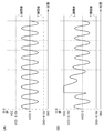
図2(A)は、ノイズが重畳していない地絡検知用信号の1例を示し、図2(B)は、ノイズが重畳している地絡検知用信号の1例を示す。図1(A)の分圧回路1pのオペアンプは、図1(B)の単一の電源Eで作動することが好ましく、この場合、分圧回路1pのオペアンプの出力電圧の最大値及び最小値は、単一の電源Eの電源電圧に依存する。具体的には、単一の電源Eの電源電圧が例えばVCCの高電圧電源及び例えばGNDの低電源電圧で構成される時に、オペアンプの出力電圧の最大値及び最小値は、それぞれVCC及びGNDである。同様に、図1(A)の分圧回路1nのオペアンプも、図1(B)の単一の電源Eで作動することが好ましく、この場合、分圧回路1nのオペアンプの出力電圧の最大値及び最小値も、それぞれVCC及びGNDである。従って、地絡検知用信号がノイズを有しない時に、信号処理部1p,1nの出力電圧は、その最大値(VCC)を超えず、また、その最小値(GND)を下回れない(図2(A)参照)。
FIG. 2A illustrates an example of a ground fault detection signal on which noise is not superimposed, and FIG. 2B illustrates an example of a ground fault detection signal on which noise is superimposed. The operational amplifier of the voltage dividing circuit 1p shown in FIG. 1A is preferably operated by the single power source E shown in FIG. 1B. In this case, the maximum value and the minimum value of the output voltage of the operational amplifier of the voltage dividing circuit 1p are used. Depends on the power supply voltage of a single power supply E. Specifically, when the power supply voltage of the single power supply E is composed of a high voltage power supply of, for example, VCC and a low power supply voltage of, for example, GND, the maximum value and the minimum value of the output voltage of the operational amplifier are VCC and GND, respectively. is there. Similarly, the operational amplifier of the
なお、地絡検知用信号が地絡の発生を表す場合は、信号処理部1p,1nの出力電圧が、例えばVCC/2の一定電圧を有し、従って、図1(B)の地絡検知用信号の振幅Vtは、所定の振幅よりも小さくなり、例えばゼロになる。
When the ground fault detection signal indicates the occurrence of a ground fault, the output voltage of the
また、地絡検知用信号が地絡の発生を表さない場合は、例えば図2(A)に示されるように、地絡検知用信号の振幅Vtは、所定の振幅であるか又はそれよりも大きく、且つVCCよりも小さい。 When the ground fault detection signal does not indicate the occurrence of the ground fault, for example, as shown in FIG. 2A, the amplitude Vt of the ground fault detection signal is a predetermined amplitude or higher. And smaller than VCC.
地絡検知用信号が地絡の発生を表さない場合であって地絡検知用信号がノイズ(第1の電源線路SpのインピーダンスZSpと第2の電源線路SnのインピーダンスZSnとの差が変化することにより発生するバンドパスフィルタ応答ノイズ)を有する時に、信号処理部1p,1nの出力電圧は、例えば、その最大値(VCC)を超え(図2(B)参照)、或いは、その最小値(GND)を下回る可能性がある。
When the ground fault detection signal does not represent the occurrence of a ground fault, the ground fault detection signal is noise (the difference between the impedance ZSp of the first power supply line Sp and the impedance ZSn of the second power supply line Sn changes). The output voltage of the
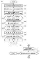
図3(A)は、図1(A)の地絡検知装置Aの動作例を表すフローチャートを示す。地絡検知装置Aの地絡検知部4aは、アナログ回路から構成されるバントパスフィルタ3でフィルタ処理された後の地絡検知用信号(固定の周波数を有する交流信号)の値を所定の間隔(A/D変換周期)で取得する(図3(A)のステップST01)。地絡検知部4aは、1例として、交流信号の1周期分の交流信号の値を取得することができる。地絡検知部4aは、例えば1周期分の波形の最大値及び最小値を認識し、波形の振幅を取得する(ステップST02)。具体的には、波形の最大値と最小値との差を波形の振幅として算出した後に、地絡検知部4aは、その算出された振幅に対する地絡抵抗値(仮の値)を例えばテーブル、計算式等で形成されたマップを参照することによって取得する(ステップST03)。
FIG. 3A shows a flowchart showing an operation example of the ground fault detection apparatus A of FIG. The ground
地絡検知部4aは、例えば1周期分の波形のすべてが地絡検知部4aに設定される下限閾値及び上限閾値の間に入っているか否かを判定する(ステップST04)。具体的には、地絡検知部4aは、波形の最小値が下限閾値以上であり、且つ波形の最大値が上限閾値以下である時に、ステップST05を実行する。他方、例えば1周期分の波形の何れかの部分が地絡検知部4aに設定される下限閾値から上限閾値までの範囲外である時に、具体的には、波形の最小値が下限閾値よりも小さい時に、或いは、波形の最大値が上限閾値よりも大きい時に、地絡検知部4aは、地絡抵抗値(仮の値)を破棄して、ステップST01に戻る。
For example, the ground
ステップST05において、地絡検知部4aは、ステップST02で算出された振幅が振幅閾値以上であるか否かを判定する。ここで、振幅閾値は、非地絡が明らかであり、言い換えれば、地絡抵抗値(仮の値)が明らかに高く安全が保たれている時の地絡抵抗値(例えば1000[kΩ])に対応する振幅が設定されている。振幅が振幅閾値以上である時に、その後の処理を省略するために、地絡検知部4aは、地絡抵抗値(仮の値)を破棄して、ステップST01に戻る。
In step ST05, the ground
もちろん、地絡検知部4aは、ステップST05を省略して、ステップST06を実行してもよい。或いは、地絡検知部4aは、ステップST05を変更して、振幅が振幅閾値以上である時に、地絡抵抗値を1000[kΩ]に更新してもよい。
Of course, the ground
ステップST06において、地絡検知部4aは、ステップST02で算出された振幅(最新値)の変動が大きいか否かを判定することができる。
In step ST06, the ground
もちろん、地絡検知部4aは、ステップST06を省略して、ステップST07を実行してもよい。ステップST06において、具体的には、地絡検知部4aは、最新のステップST02で算出された振幅(最新値)と前回のステップST02で算出された振幅(前回値)との差(具体的には、その差の絶対値)が変動閾値(振幅変動閾値)以下であるか否かを判定する。加えて、好ましくは、地絡検知部4aは、最新のステップST02で算出された振幅(最新値)と前々回のステップST02で算出された振幅(前々回値)との差(具体的には、その差の絶対値)が変動閾値以下であるか否かを判定することができる。
Of course, the ground
ステップST02で算出された振幅(最新値)の変動が大きい時に、地絡検知部4aは、地絡抵抗値(仮の値)を破棄して、ステップST01に戻る。言い換えれば、車両の電源投入時等のバッテリBの電源(両端電圧)に変動が大きく、このようなノイズに起因して振幅(最新値)の変動が大きい時に、地絡の検知が実行されないので、地絡の検知精度は、より一層向上する。
When the fluctuation of the amplitude (latest value) calculated in step ST02 is large, the ground
ステップST02で算出された振幅(最新値)の変動が小さい時に、地絡検知部4aは、地絡抵抗値(仮の値)を採用して、地絡抵抗値(現在の値又は実際の値)を更新することができる(ステップST07)。地絡検知部4aは、更新された地絡抵抗値(現在の値又は実際の値)が地絡判定閾値以下である時に、地絡の発生を検知する(ステップST08,ST09)。
When the fluctuation of the amplitude (latest value) calculated in step ST02 is small, the ground
図3(B)は、図3(A)のフローチャートに関連する地絡検知装置Aの他の動作例を表す他のフローチャートを示す。地絡検知装置Aの電圧検出部4bは、差動増幅器7の出力信号(バッテリBの両端電圧を表す直流信号)の値を所定の間隔(A/D変換周期)で取得する(図3(B)のステップST11)。ステップST12において、電圧検出部4bは、例えば1周期分の波形の最大値及び最小値を認識し、波形の振幅(波高)を取得し、その波高が大きいか否かを判定し、直流信号の波高が波高閾値以上である時に、地絡検知部4aは、直流信号の成分(ノイズ)が地絡抵抗値の算出に用いられる地絡検知用信号の振幅Vtに大きく影響を与えていると判断し、このノイズを含む地絡検知用信号から算出される地絡抵抗値(仮の値)を破棄して、ステップST01に戻る。言い換えれば、地絡検知部4aは、ステップST03を実行した後であって、ステップST07を実行する前に、電圧検出部4bの判定結果を得て、地絡の検知を実行するか否かを決定してもよい。例えば、ステップST06を実行した後に、ステップST11,ST12を実行してもよい。
FIG. 3B shows another flowchart showing another operation example of the ground fault detection apparatus A related to the flowchart of FIG. The
車両走行などの、モータの駆動又は回路によって、バッテリBの両端電圧に地絡検知用信号の固定の周波数と一致する周波数の変動(ノイズ)が発生し得る。そのため、このようなノイズに起因して地絡抵抗値(仮の値)の算出にノイズが発生する場合には、地絡検知部4aによって、地絡の検知が実行されないため、地絡の検知精度は、より一層向上する。
Due to driving of the motor or a circuit such as vehicle running, a voltage fluctuation (noise) that matches the fixed frequency of the ground fault detection signal may occur in the voltage across the battery B. Therefore, when noise occurs in the calculation of the ground fault resistance value (temporary value) due to such noise, the ground fault detection is not performed by the ground
なお、バッテリBの両端電圧に地絡検知用信号の固定の周波数と一致する周波数(変動周波数)の変動(ノイズ)が発生し、地絡検知用信号の固定の周波数の位相がバッテリBの両端電圧の変動周波数の位相が同位相である時に、地絡検知部4aによって算出される地絡検知用信号波形の振幅Vtは、理論的には増加し、地絡検知用の信号から算出される地絡抵抗値も増加する。
In addition, the fluctuation (noise) of the frequency (fluctuation frequency) that matches the fixed frequency of the ground fault detection signal occurs in the voltage at both ends of the battery B, and the phase of the fixed frequency of the ground fault detection signal is the both ends of the battery B. When the phase of the voltage fluctuation frequency is the same, the amplitude Vt of the ground fault detection signal waveform calculated by the ground
また、バッテリBの両端電圧に地絡検知用信号の固定の周波数と一致する周波数(変動周波数)の変動(ノイズ)が発生し、地絡検知用信号の固定の周波数の位相がバッテリBの両端電圧の変動周波数の位相が逆位相である時に、地絡検知部4aによって算出される地絡検知用信号波形の振幅Vtは、理論的には減少し、地絡検知用の信号から算出される地絡抵抗値も減少する。
In addition, a fluctuation (noise) of a frequency (fluctuation frequency) that matches the fixed frequency of the ground fault detection signal is generated in the voltage across the battery B, and the phase of the fixed frequency of the ground fault detection signal is the both ends of the battery B. When the phase of the voltage fluctuation frequency is opposite, the amplitude Vt of the ground fault detection signal waveform calculated by the ground
具体的には、ステップST12において、電圧検出部4bは、バッテリBの両端電圧の所定の周波数強度(差動増幅器7から電圧検知部4bに入力される直流信号(被検知信号の例えば1周期分の直流信号)から算出される波高)が閾値(強度閾値又は波高閾値)以上である場合に、地絡検知部4aは、地絡検知用信号に含まれる直流信号成分が地絡検知用信号に影響を与えていると判断して、地絡検知用の信号から算出される地絡抵抗値(仮の値)を破棄して、ステップST01に戻る。
Specifically, in step ST12, the
なお、バッテリBの両端電圧に地絡検知用信号の固定の周波数と一致する周波数の変動(ノイズ)が発生する時に、セル電圧にも地絡検知用信号の固定の周波数と一致する周波数の変動(ノイズ)が発生し得る。従って、電圧検出部4bの判定に加えて、或いは電圧検出部4bの判定に代えて、演算処理部4は、少なくとも1つのセル電圧又はすべてのセル電圧を表す直流信号の値を所定の間隔(A/D変換周期)で取得し、このような直流信号の例えば1周期分の波高が波高閾値以上である時に、地絡検知部4aは、地絡抵抗値(仮の値)を破棄して、ステップST01に戻ってもよい。
When a voltage fluctuation (noise) that matches the fixed frequency of the ground fault detection signal occurs in the voltage across the battery B, the cell voltage also changes in frequency that matches the fixed frequency of the ground fault detection signal. (Noise) may occur. Therefore, in addition to the determination of the
本発明は、上述の例示的な実施形態に限定されず、また、当業者は、上述の例示的な実施形態を特許請求の範囲に含まれる範囲まで、容易に変更することができるであろう。 The present invention is not limited to the above-described exemplary embodiments, and those skilled in the art will be able to easily modify the above-described exemplary embodiments to the extent included in the claims. .
1p,1n・・・分圧回路、2・・・加算回路、3・・・バンドパスフィルタ(BPF)、4・・・演算処理部、4a・・・地絡検知部、4b・・・電圧検出部、4c・・・基準信号発生器、5・・・電圧変換回路、6p,6n・・・結合回路、7・・・差動増幅器、A・・・地絡検知装置、B・・・バッテリ、INV・・・インバータ、S1,S2,SM・・・検出回路、Sp,Sn・・・電源線路(伝送線路)。 1p, 1n ... voltage divider circuit, 2 ... adder circuit, 3 ... band pass filter (BPF), 4 ... arithmetic processing unit, 4a ... ground fault detection unit, 4b ... voltage Detection unit, 4c ... reference signal generator, 5 ... voltage conversion circuit, 6p, 6n ... coupling circuit, 7 ... differential amplifier, A ... ground fault detection device, B ... Battery, INV: Inverter, S1, S2, SM: Detection circuit, Sp, Sn: Power supply line (transmission line).
Claims (2)
前記地絡検知用信号を地絡検知対象である直流電源の両端にそれぞれ対応する第1の電源線路と第2の電源線路とに供給する信号供給部と、
前記第1の電源線路と前記第2の電源線路とから得られた第1及び第2の地絡検知用信号をそれぞれ含む第1及び第2の被検知信号を信号処理する信号処理部と、
前記信号処理部の第1及び第2の出力信号を加算し、単一の加算信号を生成する加算回路と、
前記加算回路によって生成された前記単一の加算信号から前記固定の周波数に相当する周波数成分を前記地絡検知用信号として抽出するバントパスフィルタと、
前記バントパスフィルタから出力される前記地絡検知用信号に基づいて前記直流電源の地絡を検知する地絡検知部と、
を備える地絡検知装置であって、
前記地絡検知部は、前記バントパスフィルタでフィルタ処理された後の前記地絡検知用信号の値が下限閾値よりも小さい又は上限閾値よりも大きい時に、前記バンドパスフィルタでは除去することができないノイズであって前記第1の電源線路のインピーダンスと前記第2の電源線路のインピーダンスとの差が変化することにより発生する前記ノイズが前記地絡検知用信号に重畳していると判断し、前記地絡の検知を無効化することを特徴とする地絡検知装置。 A signal generator for generating a ground fault detection signal which is an AC signal having a fixed frequency;
A signal supply unit that supplies the ground fault detection signal to a first power line and a second power line respectively corresponding to both ends of a DC power source that is a ground fault detection target;
A signal processing unit that performs signal processing on the first and second detected signals respectively including the first and second ground fault detection signals obtained from the first power supply line and the second power supply line;
An adding circuit for adding the first and second output signals of the signal processing unit to generate a single added signal;
A band pass filter that extracts a frequency component corresponding to the fixed frequency from the single addition signal generated by the addition circuit as the ground fault detection signal;
A ground fault detection unit that detects a ground fault of the DC power supply based on the ground fault detection signal output from the band pass filter;
A ground fault detection device comprising:
The ground fault detection unit cannot be removed by the band pass filter when the value of the ground fault detection signal after being filtered by the band pass filter is smaller than a lower threshold or larger than an upper threshold. Determining that the noise, which is a noise and the difference between the impedance of the first power supply line and the impedance of the second power supply line, is superimposed on the ground fault detection signal, A ground fault detection device characterized by invalidating ground fault detection.
前記バントパスフィルタは、前記加算回路からの前記単一の加算信号を前記ハイパスフィルタでフィルタ処理し、前記ハイパスフィルタでフィルタ処理された前記単一の加算信号を前記ローパスフィルタによってフィルタ処理することで前記地絡検知用信号を抽出することを特徴とする請求項1に記載の地絡検知装置。 The band pass filter is composed of a combination of a high pass filter and a low pass filter,
The band pass filter is configured to filter the single addition signal from the adder circuit with the high pass filter and filter the single addition signal filtered with the high pass filter with the low pass filter. The ground fault detection device according to claim 1, wherein the ground fault detection signal is extracted.
Priority Applications (1)
| Application Number | Priority Date | Filing Date | Title |
|---|---|---|---|
| JP2016138819A JP2018009875A (en) | 2016-07-13 | 2016-07-13 | Ground fault detector |
Applications Claiming Priority (1)
| Application Number | Priority Date | Filing Date | Title |
|---|---|---|---|
| JP2016138819A JP2018009875A (en) | 2016-07-13 | 2016-07-13 | Ground fault detector |
Publications (1)
| Publication Number | Publication Date |
|---|---|
| JP2018009875A true JP2018009875A (en) | 2018-01-18 |
Family
ID=60995393
Family Applications (1)
| Application Number | Title | Priority Date | Filing Date |
|---|---|---|---|
| JP2016138819A Pending JP2018009875A (en) | 2016-07-13 | 2016-07-13 | Ground fault detector |
Country Status (1)
| Country | Link |
|---|---|
| JP (1) | JP2018009875A (en) |
Cited By (3)
| Publication number | Priority date | Publication date | Assignee | Title |
|---|---|---|---|---|
| WO2020011742A1 (en) * | 2018-07-11 | 2020-01-16 | Siemens Aktiengesellschaft | Ground fault detection circuit and apparatus |
| WO2020011740A1 (en) * | 2018-07-11 | 2020-01-16 | Siemens Aktiengesellschaft | Ground fault detection circuit and device |
| JP2022062862A (en) * | 2020-10-09 | 2022-04-21 | 日立Astemo株式会社 | Ground fault detector |
Citations (5)
| Publication number | Priority date | Publication date | Assignee | Title |
|---|---|---|---|---|
| JP2003274504A (en) * | 2002-03-15 | 2003-09-26 | Denso Corp | Ground fault detecting circuit for electric vehicle |
| JP2009085830A (en) * | 2007-10-01 | 2009-04-23 | Toyota Industries Corp | Insulation resistance deterioration detector for industrial vehicle |
| JP2014017974A (en) * | 2012-07-09 | 2014-01-30 | Honda Motor Co Ltd | Ground fault detection system for ungrounded circuit |
| EP2869075A1 (en) * | 2013-11-04 | 2015-05-06 | ABB Technology AG | System and method for detecting a leakage from power cables of a DC bus to ground |
| JP2015210085A (en) * | 2014-04-23 | 2015-11-24 | 株式会社デンソー | Ground fault judgment device |
-
2016
- 2016-07-13 JP JP2016138819A patent/JP2018009875A/en active Pending
Patent Citations (5)
| Publication number | Priority date | Publication date | Assignee | Title |
|---|---|---|---|---|
| JP2003274504A (en) * | 2002-03-15 | 2003-09-26 | Denso Corp | Ground fault detecting circuit for electric vehicle |
| JP2009085830A (en) * | 2007-10-01 | 2009-04-23 | Toyota Industries Corp | Insulation resistance deterioration detector for industrial vehicle |
| JP2014017974A (en) * | 2012-07-09 | 2014-01-30 | Honda Motor Co Ltd | Ground fault detection system for ungrounded circuit |
| EP2869075A1 (en) * | 2013-11-04 | 2015-05-06 | ABB Technology AG | System and method for detecting a leakage from power cables of a DC bus to ground |
| JP2015210085A (en) * | 2014-04-23 | 2015-11-24 | 株式会社デンソー | Ground fault judgment device |
Cited By (4)
| Publication number | Priority date | Publication date | Assignee | Title |
|---|---|---|---|---|
| WO2020011742A1 (en) * | 2018-07-11 | 2020-01-16 | Siemens Aktiengesellschaft | Ground fault detection circuit and apparatus |
| WO2020011740A1 (en) * | 2018-07-11 | 2020-01-16 | Siemens Aktiengesellschaft | Ground fault detection circuit and device |
| CN110780223A (en) * | 2018-07-11 | 2020-02-11 | 西门子股份公司 | Ground fault detection circuit and device |
| JP2022062862A (en) * | 2020-10-09 | 2022-04-21 | 日立Astemo株式会社 | Ground fault detector |
Similar Documents
| Publication | Publication Date | Title |
|---|---|---|
| US12385981B2 (en) | Battery monitoring device including calculation of impedance using independent electrical path to a response signal input | |
| JP4924711B2 (en) | Power regeneration converter | |
| US9255957B2 (en) | Earth fault detection circuit and power source device | |
| JP2018040710A (en) | Voltage detector | |
| CN107091964B (en) | Ground detection device | |
| FR2980053B1 (en) | METHOD FOR MONITORING THE CAPACITIVE FILTER OF A BATTERY CHARGER | |
| CN106068458A (en) | The apparatus and method that electric insulation in the vehicle power supply system to vehicle is monitored | |
| JP2018009875A (en) | Ground fault detector | |
| JP6725349B2 (en) | Ground fault detector | |
| JP6229584B2 (en) | Ground fault judgment device | |
| JP2018009877A (en) | Ground fault detector | |
| Shaffer et al. | On-line detection of DC arc faults using hurst exponents for hybrid-electric vehicles | |
| JP6438729B2 (en) | Insulation performance diagnostic device and method of setting capacitance value of pseudo capacitor | |
| JP6229585B2 (en) | Ground fault judgment device | |
| JP5761044B2 (en) | Insulation abnormality detector | |
| JP6394428B2 (en) | Leakage determination device | |
| JP6229586B2 (en) | Ground fault judgment device | |
| JP5417862B2 (en) | Ground fault detection device for vehicles | |
| JP7111075B2 (en) | battery monitor | |
| JP2013113710A (en) | Insulation abnormality detection device | |
| WO2013161870A1 (en) | Insulation abnormality detection device | |
| JP2013134234A (en) | Insulation abnormality detection device | |
| CN119044820B (en) | System and method for detecting ground fault of charging pile system in real time | |
| CN110441603B (en) | Electric leakage blocking sampling circuit and detection method | |
| JP2016031298A (en) | Insulation abnormality detector |
Legal Events
| Date | Code | Title | Description |
|---|---|---|---|
| A621 | Written request for application examination |
Free format text: JAPANESE INTERMEDIATE CODE: A621 Effective date: 20190318 |
|
| A977 | Report on retrieval |
Free format text: JAPANESE INTERMEDIATE CODE: A971007 Effective date: 20200122 |
|
| A131 | Notification of reasons for refusal |
Free format text: JAPANESE INTERMEDIATE CODE: A131 Effective date: 20200128 |
|
| A521 | Request for written amendment filed |
Free format text: JAPANESE INTERMEDIATE CODE: A523 Effective date: 20200323 |
|
| A02 | Decision of refusal |
Free format text: JAPANESE INTERMEDIATE CODE: A02 Effective date: 20200526 |