JP2018009867A - Magnetic flux leakage inspection device - Google Patents
Magnetic flux leakage inspection device Download PDFInfo
- Publication number
- JP2018009867A JP2018009867A JP2016138601A JP2016138601A JP2018009867A JP 2018009867 A JP2018009867 A JP 2018009867A JP 2016138601 A JP2016138601 A JP 2016138601A JP 2016138601 A JP2016138601 A JP 2016138601A JP 2018009867 A JP2018009867 A JP 2018009867A
- Authority
- JP
- Japan
- Prior art keywords
- magnetic flux
- probe
- leakage magnetic
- cylindrical body
- guide rail
- Prior art date
- Legal status (The legal status is an assumption and is not a legal conclusion. Google has not performed a legal analysis and makes no representation as to the accuracy of the status listed.)
- Pending
Links
Images

Landscapes
- Investigating Or Analyzing Materials By The Use Of Magnetic Means (AREA)
Abstract
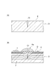
【課題】対象物の内側の表面を容易に検査することが可能な漏洩磁束探傷装置を提供する。【解決手段】漏洩磁束探傷装置1は、探触子4と、対象物である筒体2の外側から内側まで延在し、探触子4を筒体2の内側で保持する保持部であるガイドレール6と、筒体2の内側の表面3に対して、表面3に沿う方向に探触子4を相対的に移動させる移動機構5と、を備える。漏洩磁束探傷装置1では、探触子4が対象物の内側で保持部によって保持され、きずに起因して表面から漏洩する磁束が検出される。【選択図】図1A leakage magnetic flux flaw detector capable of easily inspecting the inner surface of an object is provided. A leakage magnetic flux flaw detector 1 includes a probe 4 and a holder extending from the outside to the inside of a cylindrical body 2 as an object and holding the probe 4 inside the cylindrical body 2. A guide rail 6 and a moving mechanism 5 for moving the probe 4 relative to the inner surface 3 of the cylindrical body 2 in a direction along the surface 3 are provided. In the leakage magnetic flux flaw detector 1, the probe 4 is held inside the object by a holding part, and magnetic flux leaking from the surface due to flaws is detected. [Selection drawing] Fig. 1
Description
本発明は、漏洩磁束探傷装置に関する。 The present invention relates to a leakage magnetic flux flaw detector.
従来、強磁性体である対象物の表面または表層のきずを探傷する非破壊試験として、磁粉探傷試験が知られている(例えば特許文献1参照)。磁粉探傷試験では、対象物を磁化すると共に、対象物の表面に磁粉を付着させて、きずからの漏洩磁束に引き寄せられた磁粉による指示模様を確認する。例えば、作業者がブラックライトを用いて紫外線を放射させ、蛍光磁粉を発光させて、きずに起因する指示模様を目視により確認する。 Conventionally, a magnetic particle flaw detection test is known as a non-destructive test for flaw detection on the surface of a target object that is a ferromagnetic material or on a surface layer (for example, see Patent Document 1). In the magnetic particle flaw detection test, the object is magnetized, and magnetic particles are adhered to the surface of the object, and the indication pattern by the magnetic particles attracted to the leakage magnetic flux from the flaw is confirmed. For example, an operator radiates ultraviolet rays using a black light, emits fluorescent magnetic powder, and visually confirms an indication pattern caused by a flaw.
しかしながら、対象物の内側の表面を検査する場合において、作業者が対象物の内側に入れない場合には、従来の磁粉探傷試験を適用することは困難であった。また、外側から対象物の内側の表面を覗いて、指示模様を視認することは容易ではなかった。 However, in the case of inspecting the inner surface of the object, it is difficult to apply the conventional magnetic particle flaw detection test if the worker cannot enter the object. In addition, it is not easy to view the instruction pattern by looking into the inner surface of the object from the outside.
本発明は、対象物の内側の表面を容易に検査することが可能な漏洩磁束探傷装置を提供することを目的とする。 An object of the present invention is to provide a leakage magnetic flux flaw detector capable of easily inspecting an inner surface of an object.
本発明の漏洩磁束探傷装置は、漏洩磁束探触子と、対象物の外側から内側まで延在し、漏洩磁束探触子を対象物の内側で保持する保持部と、対象物の内側の表面に対して、漏洩磁束探触子を表面に沿う方向に相対的に移動させる移動機構と、を備える。 A leakage magnetic flux flaw detector of the present invention includes a leakage magnetic flux probe, a holding portion that extends from the outside to the inside of the object, and holds the leakage magnetic flux probe inside the object, and a surface inside the object. On the other hand, a moving mechanism that relatively moves the leakage flux probe in the direction along the surface is provided.
この漏洩磁束探傷装置では、漏洩磁束探触子が対象物の内側で保持部によって保持され、きずに起因して表面から漏洩する磁束を漏洩磁束探触子によって検出するので、作業者が対象物の内部に入ることなく、対象物の内側の表面を容易に検査することができる。また、この漏洩磁束探傷装置では、漏洩磁束探触子を対象物の内側の表面に沿う方向に相対的に移動させることができるので、対象物の表面を所定の範囲にわたって検査することが可能である。 In this leakage magnetic flux flaw detector, the leakage magnetic flux probe is held by the holding portion inside the object, and the magnetic flux leaking from the surface due to the flaw is detected by the leakage magnetic flux probe. The inside surface of the object can be easily inspected without entering the interior of the object. Further, in this leakage magnetic flux flaw detector, the leakage magnetic flux probe can be relatively moved in the direction along the inner surface of the object, so that the surface of the object can be inspected over a predetermined range. is there.
また、保持部は、表面に沿う方向のうちの一方向に延在する案内部材を含み、移動機構は、案内部材に沿って移動する移動部を含む構成でよい。この漏洩磁束探傷装置では、移動部が案内部材に沿って移動するので、漏洩磁束探触子の移動方向を一方向に沿って拘束することができる。これにより、漏洩磁束探触子が存在する範囲が限定されるので、きずを検出した位置を確実に把握することができる。 The holding unit may include a guide member that extends in one of the directions along the surface, and the moving mechanism may include a moving unit that moves along the guide member. In this leakage magnetic flux flaw detector, since the moving part moves along the guide member, the moving direction of the leakage magnetic flux probe can be restricted along one direction. Thereby, since the range in which the leakage magnetic flux probe exists is limited, it is possible to reliably grasp the position where the flaw is detected.
また、対象物は筒体であり、案内部材は、筒体の軸線に沿って延在し、移動機構は、移動部から筒体の径方向に延在し探触子を支持する支持部を備える構成でもよい。この漏洩磁束探傷装置では、筒体の軸線に沿って案内部材が配置されているので、移動部を筒体の軸線に沿って移動させることができる。また、筒体の径方向に延在する支持部によって、探触子を筒体の内側の表面に接近させて支持することが可能となる。このため、筒体の内側の表面の検査を好適に行うことができる。 Further, the object is a cylinder, the guide member extends along the axis of the cylinder, and the moving mechanism includes a support unit that extends from the moving unit in the radial direction of the cylinder and supports the probe. The structure provided may be sufficient. In this leakage magnetic flux flaw detector, since the guide member is disposed along the axis of the cylinder, the moving part can be moved along the axis of the cylinder. In addition, the probe can be supported by being brought close to the inner surface of the cylinder by the support portion extending in the radial direction of the cylinder. For this reason, the test | inspection of the inner surface of a cylinder can be performed suitably.
本発明によれば、対象物の内側の表面を容易に検査することが可能な漏洩磁束探傷装置を提供することができる。 ADVANTAGE OF THE INVENTION According to this invention, the leakage magnetic flux flaw detector which can test | inspect easily the surface inside a target object can be provided.
以下、本発明の好適な実施形態について、図面を参照しながら詳細に説明する。なお、各図において同一部分又は相当部分には同一の符号を付し、重複する説明は省略する。 DESCRIPTION OF EXEMPLARY EMBODIMENTS Hereinafter, preferred embodiments of the invention will be described in detail with reference to the drawings. In addition, in each figure, the same code | symbol is attached | subjected to the same part or an equivalent part, and the overlapping description is abbreviate | omitted.
図1に示される漏洩磁束探傷装置1は、漏洩磁束探傷法(Magnetic Flux Leakage:MFL)を適用して、対象物である例えば筒体2の内側の表面(内面)3を検査するものである。筒体2は、例えばジェットエンジンの回転軸(円筒体)である。筒体2は、円筒体でもよく、角筒体でもよい。また、対象物は、筒体に限定されず、箱形のものでもよく、断面がU字状を成すものでもよく、断面がC字状を成すものでもよい。また、対象物は、軸線方向Xの長さが、径方向Rの長さより短いリング状のものでもよい。また、対象物は、軸線方向Xにおいて、径方向Rの長さが異なるものでもよい。
A leakage
漏洩磁束探傷法とは、図2(A)に示されるように、強磁性体からなる対象物Oの表面または表層に存在し得るきずCrを、磁気センサTを用いて探索する検査法である。図2(B)に示されるように、漏洩磁束探傷法では、種々の方法により対象物Oを磁化することにより、対象物Oに所定方向の磁束Fを発生させる。磁束Fを遮るきずCrがある場合には、磁束FはきずCrを迂回するように表面(探傷面E)から外部に漏洩し、漏洩磁束Faが発生する。 The magnetic flux leakage flaw detection method is an inspection method that uses a magnetic sensor T to search for flaws Cr that may exist on the surface or surface of an object O made of a ferromagnetic material, as shown in FIG. . As shown in FIG. 2B, in the leakage magnetic flux flaw detection method, a magnetic flux F in a predetermined direction is generated on the object O by magnetizing the object O by various methods. When there is a crack Cr that blocks the magnetic flux F, the magnetic flux F leaks to the outside from the surface (flaw detection surface E) so as to bypass the crack Cr, and a leakage magnetic flux Fa is generated.
漏洩磁束探傷法では、対象物Oの探傷面E上で磁気センサTを走査方向Dに走査させることにより、漏洩磁束Faが検出される。磁気センサTからの信号を用いる漏洩磁束探傷法は、従来採用されてきた磁粉探傷法に比して、探傷の自動化と結果のデジタル化とが容易であるという利点を有する。 In the leakage magnetic flux flaw detection method, the magnetic flux leakage Fa is detected by scanning the magnetic sensor T in the scanning direction D on the flaw detection surface E of the object O. The leakage magnetic flux flaw detection method using a signal from the magnetic sensor T has an advantage that the flaw detection automation and the digitization of the result are easier than the magnetic particle flaw detection method conventionally employed.
漏洩磁束探傷装置1は、図1に示されるように、表面3を探傷する探触子(漏洩磁束探触子)4と、探触子4を移動させる移動機構5と、移動機構5における移動を案内するガイドレール(案内部材、保持部)6とを備える。
As shown in FIG. 1, the leakage magnetic
図3に示されるように、探触子4は、計装アンプ基板11と、計装アンプ基板11に接続されたフレキシブル基板10とを含む。計装アンプ基板11は、探触子4から出力される信号を増幅させる。フレキシブル基板10は、計装アンプ基板11に対して差し込まれ、コネクタ接続されている。探触子4において、フレキシブル基板10のみを交換することが可能になっている。フレキシブル基板10には、たとえば複数の磁気センサ12が搭載されている。
As shown in FIG. 3, the
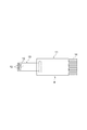
移動機構5は、ガイドレール6に沿って移動する移動体(移動部)7と、移動体7に対して探触子4を支持するアーム(支持部)8と、を備える。
The moving mechanism 5 includes a moving body (moving part) 7 that moves along the guide rail 6 and an arm (supporting part) 8 that supports the
移動体7には、ガイドレール6を挿通させる貫通孔が設けられている。移動体7の貫通孔の断面形状は、ガイドレール6の断面形状に対応している。移動体7の貫通孔にガイドレール6が挿通されることで、移動体7がガイドレール6に保持されている。なお、貫通孔に代えて溝が形成されていてもよい。また、移動体7には、例えば、駆動源である電動モータ、電動モータによって回転駆動される複数の車輪が設けられている。移動体7では、電動モータによって車輪が回転駆動され、ガイドレール6に対して動力が伝達されて、移動体7がガイドレール6に沿って移動する。 The moving body 7 is provided with a through hole through which the guide rail 6 is inserted. The cross-sectional shape of the through hole of the moving body 7 corresponds to the cross-sectional shape of the guide rail 6. The moving body 7 is held by the guide rail 6 by inserting the guide rail 6 through the through hole of the moving body 7. A groove may be formed instead of the through hole. Moreover, the moving body 7 is provided with, for example, an electric motor that is a drive source and a plurality of wheels that are rotationally driven by the electric motor. In the moving body 7, wheels are driven to rotate by the electric motor, power is transmitted to the guide rail 6, and the moving body 7 moves along the guide rail 6.
アーム8は、例えば、移動体7から、移動体7の移動方向と交差する方向に延在する棒状の部材である。アーム8は、筒体2の径方向Rに延在し、筒体2の軸線L2側から筒体2の内側の表面3の近傍まで延在している。アーム8の一端側は移動体7に固定され、アーム8の他端側には探触子4が取り付けられている。アーム8は、ガイドレール6が延在する方向に対して直交する方向に延在している構成でもよく、ガイドレール6に対して傾斜するように延在している構成でもよい。
The
また、アーム8は、移動体7の移動方向と交差する方向において、伸縮可能な伸縮部を含む構成でもよい。伸縮部としては、たとえば蛇腹部、エアシリンダ、バネ部などを備える構成でもよい。この構成では、アーム8を伸縮させることで、筒体2の内径に応じて、探触子4を筒体2の内側の表面3に接近、離間させることができる。
In addition, the
アーム8は、例えば、長手方向において複数の円筒体を備えるものでもよい。また、アーム8は円柱体などの棒状の部材でもよく、枠体などその他の構造を含むものでもよい。
For example, the
ガイドレール6は、所定の長さを有し、例えば、筒体2の軸線L2方向の長さより長い。ガイドレール6の長手方向に直交する断面は、例えばI字状となっている。ガイドレール6は、I字状の断面形状を有するものに限定されず、H字状の断面形状を有するものでもよく、円筒体など、その他の形状のものでもよい。
The guide rail 6 has a predetermined length, for example, longer than the length of the
ガイドレール6の両端部には、例えば一対の軸受9によって回転可能に支持されている。軸受9としては、例えばスリーブを使用することができる。ガイドレール6の両端部は円柱状を成し、軸受9の開口に挿通されて、回転可能に支持されている。 For example, a pair of bearings 9 are rotatably supported at both ends of the guide rail 6. As the bearing 9, for example, a sleeve can be used. Both end portions of the guide rail 6 have a columnar shape, are inserted through the opening of the bearing 9 and are rotatably supported.
移動機構5は、探触子4を筒体2の周方向に回転移動させる周方向移動機構を含む。周方向移動機構は、駆動源と、駆動源から出力された回転駆動力をガイドレール6に伝達する動力伝達機構とを備える。駆動源としては、例えば電動モータを使用することができる。動力伝達機構は、例えば、電動モータの出力軸に設けられた歯車、ガイドレール6に取り付けられた歯車を含む。
The moving mechanism 5 includes a circumferential movement mechanism that rotates the
周方向移動機構では、駆動源から出力された動力が動力伝達機構を介して、ガイドレール6に伝達される。これにより、ガイドレール6がこの軸回り(軸線L2回り)に回転し、移動体7、アーム8及び探触子4が一体として、ガイドレール6の軸回りに回転する。このため、探触子4は筒体2の周方向に移動する。
In the circumferential movement mechanism, the power output from the drive source is transmitted to the guide rail 6 via the power transmission mechanism. As a result, the guide rail 6 rotates about this axis (around the axis L2), and the movable body 7, the
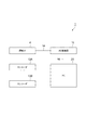
また、漏洩磁束探傷装置1は、図4に示されるように、探触子4から出力された信号を入力して所定の処理を行い、探傷試験の結果を出力するパーソナルコンピュータ(以下、PCという)20を備える。探触子4には複数のリード線14が設けられており、これらのリード線14はたとえばAD変換器15に接続されている。AD変換器15とPC20とは、USBケーブル等のケーブル16によって接続されている。
Further, as shown in FIG. 4, the leakage magnetic
また、PC20には、探触子4の位置情報を取得するためのエンコーダ13A,13Bが接続されている。エンコーダ13Aは、移動体7に連結されたワイヤを巻き取るリールの回転角を検出する。エンコーダ13Aで取得された回転角に関する情報は、PC20に出力される。PC20は、リールの回転角に基づいて、筒体2の軸線方向Xにおける移動体7の位置を算出して、探触子4の位置情報を取得する。
In addition,
また、エンコーダ13Bは、ガイドレール6の回転角を検出する。エンコーダ13Bで取得された回転角に関する情報は、PC20に出力される。PC20は、ガイドレール6の軸回りの回転角に基づいて、筒体2の周方向における探触子4の位置を算出する。
The
また、PC20は、探触子から出力される、磁束を示す信号を入力し、探傷面(筒体2の内側の表面3)Eまたは表層におけるきずCrの有無を判定するための探傷試験結果を出力する。PC20は、たとえば磁気センサ13におけるインピーダンスの変化に基づいて、きずCrの有無を判定する。また、PC20は、きずCrの有無だけでなく、きずCrの幅や長さを推定することもできる。また、PC20は記憶部を含み、この記憶部に探傷試験結果を保存することができる。
Further, the
たとえば、AD変換器15、PC20及びエンコーダ13A,13Bは、筒体2の外部に配置されている。また、リード線14は、アーム8及びガイドレール6に沿うように配置されていてもよく、その他の位置を通るように配置されていてもよい。
For example, the
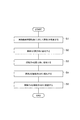
次に、図5を参照して、漏洩磁束探傷装置1を用いた筒体2の検査方法の手順について説明する。
Next, with reference to FIG. 5, the procedure of the inspection method of the
まず、漏洩磁束探傷装置1に対して筒体2を配置する工程を行う(ステップS1)。たとえば支持台を用いて筒体2を支持し、筒体2の軸線L2が延在する方向が水平方向に沿うように配置する。そして、筒体2の軸線L2に沿ってガイドレール6を配置する。
First, the process of arrange | positioning the
次に、筒体2を磁化する工程を行うと共に、筒体2の内側の表面3を探傷する工程を行う(ステップS2〜S5)。たとえば、筒体2を磁化する工程として、筒体2の周方向に筒体2を磁化する(ステップS2)。これにより、周方向に沿う磁束F2が形成される。このとき、周方向に交差する方向に延びるきずCr2が存在する場合には、漏洩磁束Faが発生する。
Next, a process of magnetizing the
続いて、周方向に磁化された探傷面Eに対して、探触子4を周方向に沿って走査する工程を行う(ステップS3)。これにより、きずCr2に起因する漏洩磁束Faが、探触子4によって検出される。PC20は、きずCr2が検出された位置を算出して記録する。また、PC20はきずCr2の長さ、深さを算出してもよい。これらのステップS2、S3を、筒体2の軸線方向Xの全長にわたって行う。たとえば、軸線方向Xにおいて複数の区間を設定して、1区間における探傷を行った後に、移動体7を軸線方向Xに移動させて、隣接する他の区間について探傷する。
Subsequently, a step of scanning the
次に、筒体2を磁化する工程として、筒体2の軸線方向Xに筒体2を磁化する(ステップS4)。これにより、軸線方向Xに沿う磁束F1が形成される。このとき、軸線方向Xに交差する方向に延びるきずCr1が存在する場合には、漏洩磁束Faが発生する。
Next, as a step of magnetizing the
続いて、軸線方向Xに磁化された探傷面Eに対して、探触子4を軸線方向Xに沿って走査する工程を行う(ステップS5)。これにより、きずCr1に起因する漏洩磁束Faが、探触子4によって検出される。PC20は、きずCr1が検出された位置を算出して記録する。これらのステップS4、S5を、筒体2の周方向の全周にわたって行う。たとえば、探触子4を軸線方向Xにおける全長について探傷した後に、移動体7を回転させて、周方向において異なる回転位置において、探触子4を軸線方向Xに走査して探傷する。このような磁化する工程及び探傷する工程を終了した後に、筒体2に対して脱磁処理を行う。なお、軸線方向Xに磁化して探傷を行った後に、周方向に磁化して探傷を行ってもよい。また、その他の方向に磁化して探傷を行ってもよい。また、探触子4の走査方向についても適宜変更してもよい。
Subsequently, a step of scanning the
このような漏洩磁束探傷装置1によれば、移動体7がガイドレール6に沿って移動して、筒体2の内部に進入し、移動体7に支持された探触子4が、筒体2の内側の表面3に接するように配置される。これにより、きずCrに起因して発生した漏洩磁束Faを探触子4によって検出することができる。このため、作業者が筒体2の内部に入る必要がなく、筒体2の内側の表面3を容易に検査することができる。また、漏洩磁束探傷装置1では、探触子4を表面3に沿って、軸線方向X及び周方向に走査することができるので、表面3の全範囲を容易に検査することができる。
According to such a leakage magnetic
また、漏洩磁束探傷装置1では、ガイドレール6に沿って移動体7を移動させることができるので、探触子4をガイドレール6が延在する方向に移動させて走査することができる。これにより、探触子4の走査方向を一方向に拘束することができ、探触子4の位置の算出が容易である。
Further, in the leakage magnetic
また、漏洩磁束探傷装置1では、ガイドレール6を軸回りに回転させることで、探触子4を筒体2の周方向に沿って走査することができる。探触子4の回転位置によらず、精度良く探傷を行うことができる。たとえば、作業者が上方を向いて検査することは容易ではないが、探触子4を回転移動させることで、上方の探傷面Eについても容易に検査を行うことができる。
Further, in the leakage magnetic
本発明は、前述した実施形態に限定されず、本発明の要旨を逸脱しない範囲で下記のような種々の変形が可能である。 The present invention is not limited to the above-described embodiments, and various modifications as described below are possible without departing from the gist of the present invention.
上記実施形態では、対象物の内側の表面3に対して、探触子4を移動させて検査しているが、探触子4を動かさずに対象物を移動させて、検査を行ってもよい。また、軸線方向Xについて検査する場合に探触子4を移動させ、周方向について検査する場合に対象物を軸線L2回りに回転させてもよい。また、軸線方向Xに探触子4を移動させる場合に、ガイドレール6を軸線方向Xに移動させることで、表面3に対して探触子4を相対的に移動させてもよい。また、軸受9が設けられておらず、ガイドレール6が回転不能であって、固定されたガイドレール6に対して、移動体7及び探触子4が回転する構成でもよい。
In the above embodiment, the
また、対象物は、軸線方向Xにおいて異なる内径を有する筒体でもよく、内側の表面は、軸線L2に対して傾斜する傾斜面を含んでもよく、軸線L2に対して直交する面を含んでもよい。また、内側の表面3は、平面でもよく、曲面でもよい。また、内側の表面は、溶接線の表面などでもよい。 Further, the object may be a cylindrical body having different inner diameters in the axial direction X, and the inner surface may include an inclined surface that is inclined with respect to the axis L2, or may include a surface that is orthogonal to the axis L2. . The inner surface 3 may be a flat surface or a curved surface. The inner surface may be the surface of a weld line.
また、ガイドレール6は、対象物を貫通するように配置されていてもよく、対象物の外側から内側の途中まで配置されている構成でもよい。ガイドレール6は、たとえば水平方向に延在するものでもよく、上下方向に延在するものでもよく、水平方向に対して傾斜して配置されるものでもよい。また、ガイドレール6は、直線的に配置されているものに限定されず、湾曲する部分を含むものでもよく、屈曲されている部分を含むものでもよい。保持部は、表面3に沿う方向のうち一方向に延在する案内部材を含む。表面3に沿う方向のうち一方向とは、表面3に平行な方向(軸線方向X、周方向)を含む。 Moreover, the guide rail 6 may be arrange | positioned so that a target object may be penetrated, and the structure arrange | positioned from the outer side of the target object to the middle of the inner side may be sufficient. The guide rail 6 may extend, for example, in the horizontal direction, may extend in the vertical direction, or may be disposed inclined with respect to the horizontal direction. Moreover, the guide rail 6 is not limited to what is arrange | positioned linearly, A curved part may be included and a curved part may be included. The holding part includes a guide member extending in one direction among the directions along the surface 3. One direction among the directions along the surface 3 includes a direction (axial direction X, circumferential direction) parallel to the surface 3.
また、対象物は、シャフトに限定されず、たとえば、航空機の部品、船舶の部品、タービンの部品でもよい。また、対象物は、複数の部品が組み立てられて構成されたものでもよい。また、対象物は、部品に限定されず、たとえば建物、橋梁、トンネル、配管、支柱、ダクト、タンク、圧力容器などの構造物でもよい。 The object is not limited to the shaft, and may be, for example, an aircraft part, a ship part, or a turbine part. Further, the object may be configured by assembling a plurality of parts. The object is not limited to a part, and may be a structure such as a building, a bridge, a tunnel, a pipe, a support, a duct, a tank, or a pressure vessel.
また、移動体7を駆動するための動力源は、電動モータに限定されず、油圧シリンダなど、その他の動力源を用いてもよい。また、たとえばラックアンドピニオンを用いて、移動体7をガイドレール6に沿って移動させてもよい。また、移動体7をガイドレール6に沿って摺動させてもよい。 The power source for driving the moving body 7 is not limited to an electric motor, and other power sources such as a hydraulic cylinder may be used. Further, the moving body 7 may be moved along the guide rail 6 using, for example, a rack and pinion. Further, the moving body 7 may be slid along the guide rail 6.
また、探触子4は、フレキシブル基板10を備えるものに限定されず、フレキシブル基板10以外の基板を備えるものでもよい。また、探触子4は、磁気センサ12が搭載された基板を交換可能なものに限定されない。漏洩磁束探傷装置1において、探触子4を交換することで、磁気センサ12を交換してもよい。また、漏洩磁束探傷装置1では、磁気センサ12が基板に搭載され、探触子4は小型化(薄型化)されている。
Further, the
1 漏洩磁束探傷装置
2 筒体(対象物)
3 内側の表面(対象物の内面)
4 探触子(漏洩磁束探触子)
5 移動機構
6 ガイドレール(保持部、案内部材)
7 移動体(移動部)
8 アーム(支持部)
1 Leakage magnetic
3 Inner surface (inner surface of the object)
4 Probe (Leakage magnetic flux probe)
5 Movement mechanism 6 Guide rail (holding part, guide member)
7 Moving body (moving part)
8 Arm (support part)
Claims (3)
対象物の外側から内側まで延在し、前記漏洩磁束探触子を前記対象物の内側で保持する保持部と、
前記対象物の内側の表面に対して、前記漏洩磁束探触子を前記表面に沿う方向に相対的に移動させる移動機構と、を備える漏洩磁束探傷装置。 A leakage flux probe;
A holding part that extends from the outside to the inside of the object, and holds the leakage magnetic flux probe inside the object;
A leakage magnetic flux flaw detector comprising: a moving mechanism that moves the leakage magnetic flux probe in a direction along the surface with respect to the inner surface of the object.
前記移動機構は、前記案内部材に沿って移動する移動部を含む請求項1に記載の漏洩磁束探傷装置。 The holding portion includes a guide member extending in one direction among the directions along the surface,
The leakage magnetic flux flaw detector according to claim 1, wherein the moving mechanism includes a moving unit that moves along the guide member.
前記案内部材は、前記筒体の軸線に沿って延在し、
前記移動機構は、前記移動部から前記筒体の径方向に延在し前記探触子を支持する支持部を備える請求項2に記載の漏洩磁束探傷装置。 The object is a cylinder;
The guide member extends along the axis of the cylindrical body,
The leakage magnetic flux flaw detector according to claim 2, wherein the moving mechanism includes a support portion that extends from the moving portion in a radial direction of the cylindrical body and supports the probe.
Priority Applications (1)
| Application Number | Priority Date | Filing Date | Title |
|---|---|---|---|
| JP2016138601A JP2018009867A (en) | 2016-07-13 | 2016-07-13 | Magnetic flux leakage inspection device |
Applications Claiming Priority (1)
| Application Number | Priority Date | Filing Date | Title |
|---|---|---|---|
| JP2016138601A JP2018009867A (en) | 2016-07-13 | 2016-07-13 | Magnetic flux leakage inspection device |
Publications (1)
| Publication Number | Publication Date |
|---|---|
| JP2018009867A true JP2018009867A (en) | 2018-01-18 |
Family
ID=60995369
Family Applications (1)
| Application Number | Title | Priority Date | Filing Date |
|---|---|---|---|
| JP2016138601A Pending JP2018009867A (en) | 2016-07-13 | 2016-07-13 | Magnetic flux leakage inspection device |
Country Status (1)
| Country | Link |
|---|---|
| JP (1) | JP2018009867A (en) |
Cited By (2)
| Publication number | Priority date | Publication date | Assignee | Title |
|---|---|---|---|---|
| CN110006989A (en) * | 2019-04-03 | 2019-07-12 | 陈岩 | A kind of magnetic fault detection system |
| CN111024805A (en) * | 2019-12-02 | 2020-04-17 | 南京航空航天大学 | Steel rail surface damage magnetic flux leakage detection device and method |
Citations (6)
| Publication number | Priority date | Publication date | Assignee | Title |
|---|---|---|---|---|
| JPS57186863U (en) * | 1981-05-23 | 1982-11-27 | ||
| JPS5821854U (en) * | 1981-08-05 | 1983-02-10 | 三菱重工業株式会社 | Internal diameter scanning mechanism |
| JPS5885152A (en) * | 1981-11-14 | 1983-05-21 | Toshiba Corp | Non-destructive self-running inspection device for flow detection inner face of hole |
| JPS6469946A (en) * | 1987-09-10 | 1989-03-15 | Hitachi Ltd | Automatic magnetic flaw detector |
| JP2003172731A (en) * | 2001-12-05 | 2003-06-20 | Daido Steel Co Ltd | Metal tube inspection device |
| US20040100256A1 (en) * | 2002-11-27 | 2004-05-27 | Gary Fickert | Oil and gas well tubular inspection system using hall effect sensors |
-
2016
- 2016-07-13 JP JP2016138601A patent/JP2018009867A/en active Pending
Patent Citations (6)
| Publication number | Priority date | Publication date | Assignee | Title |
|---|---|---|---|---|
| JPS57186863U (en) * | 1981-05-23 | 1982-11-27 | ||
| JPS5821854U (en) * | 1981-08-05 | 1983-02-10 | 三菱重工業株式会社 | Internal diameter scanning mechanism |
| JPS5885152A (en) * | 1981-11-14 | 1983-05-21 | Toshiba Corp | Non-destructive self-running inspection device for flow detection inner face of hole |
| JPS6469946A (en) * | 1987-09-10 | 1989-03-15 | Hitachi Ltd | Automatic magnetic flaw detector |
| JP2003172731A (en) * | 2001-12-05 | 2003-06-20 | Daido Steel Co Ltd | Metal tube inspection device |
| US20040100256A1 (en) * | 2002-11-27 | 2004-05-27 | Gary Fickert | Oil and gas well tubular inspection system using hall effect sensors |
Cited By (3)
| Publication number | Priority date | Publication date | Assignee | Title |
|---|---|---|---|---|
| CN110006989A (en) * | 2019-04-03 | 2019-07-12 | 陈岩 | A kind of magnetic fault detection system |
| CN111024805A (en) * | 2019-12-02 | 2020-04-17 | 南京航空航天大学 | Steel rail surface damage magnetic flux leakage detection device and method |
| CN111024805B (en) * | 2019-12-02 | 2021-11-05 | 南京航空航天大学 | A magnetic flux leakage detection device and method for surface damage of steel rails |
Similar Documents
| Publication | Publication Date | Title |
|---|---|---|
| JP5649599B2 (en) | Ultrasonic inspection apparatus and inspection method thereof | |
| US20050056105A1 (en) | Method and apparatus for inspection of reactor head components | |
| KR101986428B1 (en) | Pipe inspection robot | |
| JP5140677B2 (en) | Leakage magnetic flux inspection device for tube-shaped object | |
| CN108845027A (en) | A kind of scanning equipment for the detection of plug-in type Nozzle weld | |
| EP4411365A1 (en) | Internal duct integrity inspection equipment using magnetic metal memory | |
| JP6110735B2 (en) | UT inspection device | |
| US11821869B2 (en) | Method and apparatus for stationary electromagnetic inspection (EMI) with orthogonal magnetizers | |
| JP2008032681A (en) | Rolling device part inspection method and rolling device part inspection device | |
| JP2018009867A (en) | Magnetic flux leakage inspection device | |
| US10048225B2 (en) | Apparatus and method for inspection of tubes in a boiler | |
| JP6474070B2 (en) | Checking method for cable stayed bridges | |
| JP2007285772A (en) | Pipe inspection method, and pipe inspection device used therefor | |
| JP6388196B2 (en) | Fluorescent magnetic particle flaw detector | |
| RU2295721C2 (en) | Magnetic field flaw detector | |
| CN114813929B (en) | Adsorption-type scanning device and testing method for eddy current testing of generator retaining ring array | |
| JP2004251839A (en) | Pipe surface inspection system | |
| KR20240076095A (en) | Heat exchanger inner surface inspection device | |
| JP2003172729A (en) | Metal tube inspection device | |
| CN206489117U (en) | A kind of magnetic drives formula penetrating type eddy current probe for pipe detection | |
| JP2005017255A (en) | Regenerated pipe inspection device and regenerated pipe inspection method using this device | |
| CN116008350B (en) | A device and method for detecting DC current flow through a piston rod | |
| JP2016102665A (en) | Ultrasonic flaw detection device | |
| CN204431258U (en) | For the robot of ultrasound examination | |
| CN113748334B (en) | Inspection device for inspecting weld seams of hollow longitudinal tubular elements |
Legal Events
| Date | Code | Title | Description |
|---|---|---|---|
| A621 | Written request for application examination |
Free format text: JAPANESE INTERMEDIATE CODE: A621 Effective date: 20190530 |
|
| A977 | Report on retrieval |
Free format text: JAPANESE INTERMEDIATE CODE: A971007 Effective date: 20200214 |
|
| A131 | Notification of reasons for refusal |
Free format text: JAPANESE INTERMEDIATE CODE: A131 Effective date: 20200225 |
|
| A02 | Decision of refusal |
Free format text: JAPANESE INTERMEDIATE CODE: A02 Effective date: 20200901 |