JP2018009860A - Gas meter belly plate mounting structure - Google Patents
Gas meter belly plate mounting structure Download PDFInfo
- Publication number
- JP2018009860A JP2018009860A JP2016138432A JP2016138432A JP2018009860A JP 2018009860 A JP2018009860 A JP 2018009860A JP 2016138432 A JP2016138432 A JP 2016138432A JP 2016138432 A JP2016138432 A JP 2016138432A JP 2018009860 A JP2018009860 A JP 2018009860A
- Authority
- JP
- Japan
- Prior art keywords
- outer peripheral
- gas meter
- plate mounting
- abdominal plate
- mounting structure
- Prior art date
- Legal status (The legal status is an assumption and is not a legal conclusion. Google has not performed a legal analysis and makes no representation as to the accuracy of the status listed.)
- Granted
Links
Images
Landscapes
- Measuring Volume Flow (AREA)
Abstract
Description
この発明は、ガスの流量を計測するためのガスメータの腹板取付構造に関する。 The present invention relates to an abdominal plate mounting structure of a gas meter for measuring a gas flow rate.
各家庭やレストラン等において、ガスの使用量(流量)を計測するために設置されるガスメータとしては、特許文献1に示すようにガス圧で作動するメカニカル方式の膜式ガスメータが一般に多く使用されている。
As a gas meter installed to measure the amount of gas used (flow rate) in each home, restaurant, etc., as shown in
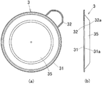
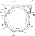
図6は従来の膜式ガスメータにおけるケース本体を示す正面図、図7は従来の腹板取付構造を示す断面図であって、図6のA−A線断面に相当する断面図である。 FIG. 6 is a front view showing a case main body in a conventional membrane gas meter, and FIG. 7 is a cross-sectional view showing a conventional abdominal plate mounting structure, which is a cross-sectional view corresponding to a cross section taken along line AA of FIG.
両図に示すように、ケース本体9の前面には、計量室用凹部91が形成されるとともに、計量室用凹部91の外周縁部には、その外周縁部が前方に盛り上がるようにして腹板取付部92が形成されている。この計量室用凹部91を閉塞するようにして計量膜93が配置されるとともに、その計量膜93を覆うようにして腹板94がケース本体9の前面にねじ止めによって固定されている。この状態において計量膜93はその外周縁部931がケース本体9の腹板取付部92と腹板94の裏面側外周縁部とに挟持されることにより固定されている。
As shown in both figures, a
このような従来のガスメータにおいて、ケース本体9の腹板取付部92には、外方に突出するようにねじ止め部922が周方向に間隔をおいて複数形成されている。
In such a conventional gas meter, a plurality of
一方、腹板94は、ケース本体9におけるねじ止め部922を含む領域をカバーできるように、腹板94の輪郭線94Lは、ねじ止め部922の外側を通るように設定されている。
On the other hand, the
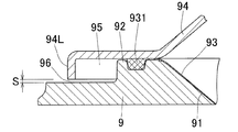
このため腹板取付部92のうち、ねじ止め部922以外の部分では、腹板94の輪郭線94Lと腹板取付部92の外側輪郭線92Lとの間隔が広くなり、腹板94の外周縁部裏面側に、メータ外部に開口する空間部95(図7参照)が形成されてしまう。
For this reason, in the portion other than the
ところで上記のようなガスメータは、使用期限が設定されており、使用期限が経過すると、新しいガスメータに取り換えるようにしている。その一方、使用期限経過後のガスメータ(使用済ガスメータ)は多くの場合、点検等が行われ、必要に応じて補修や修繕が行われて再利用されるのが一般的であるが、使用済ガスメータを点検する場合、メータ表面の塗装をショットブラストによって剥がすようにしている。 By the way, the gas meter as described above has a set expiration date, and when the expiration date has passed, it is replaced with a new gas meter. On the other hand, gas meters (used gas meters) after the expiration date are often inspected and repaired or repaired as necessary, but they are generally used. When checking a gas meter, the paint on the meter surface is removed by shot blasting.
しかしながら、ショットブラストによってガスメータの塗装を剥がす際に、図7に示すように腹板94の外周縁部裏面側に空間部95が形成されていると、その空間部95にショットブラストにおけるショット玉(投射材)が入り込んで蓄積されてしまう。このように腹板裏面側の空間部95にショット玉が蓄積されてしまうと、空間部95に蓄積されたショット玉を、取り除くという面倒な作業が必要となり、ガスメータの点検作業や修繕作業が困難であるという課題が発生する。
However, when the coating of the gas meter is peeled off by shot blasting, if a
この発明は、上記の課題に鑑みてなされたものであり、ショットブラストによりガスメータを表面処理したとしても、腹板の外周縁部裏面側に侵入したショット玉が蓄積されるのを防止することができるガスメータの腹板取付構造を提供することを目的とする。 The present invention has been made in view of the above problems, and even if the gas meter is surface-treated by shot blasting, it is possible to prevent the accumulation of shot balls that have invaded the outer peripheral edge back side of the abdominal plate. An object of the present invention is to provide an abdominal plate mounting structure for a gas meter.
上記課題を解決するため、本発明は、以下の手段を備えるものである。 In order to solve the above problems, the present invention comprises the following means.
[1]前面に計量室用凹部が設けられたケース本体を備え、そのケース本体における前記計量室用凹部の外周縁部に前方に隆起する腹板取付部が形成される一方、前記腹板取付部を含めて前記計量室用凹部を前面側から覆うように腹板が取り付けられ、前記腹板の外周端縁にその外周端縁が裏面側に折曲されるようにして縁曲げ部が形成されたガスメータの腹板取付構造であって、
前記腹板の縁曲げ部の先端と前記ケース本体の表面との間に設けられた隙間の間隔が1.0mm以上に設定されていることを特徴とするガスメータの腹板取付構造。
[1] A case main body provided with a concave portion for the measurement chamber is provided on the front surface, and an abdominal plate mounting portion that protrudes forward is formed on the outer peripheral edge of the concave portion for the measurement chamber in the case main body. A belly plate is attached so as to cover the weighing chamber recess including the front part from the front side, and an edge bent part is formed on the outer peripheral edge of the belly plate so that the outer peripheral edge is bent to the back side. An abdominal plate mounting structure for a gas meter,
An abdominal plate mounting structure for a gas meter, wherein a gap provided between a distal end of a bent portion of the abdominal plate and a surface of the case body is set to 1.0 mm or more.
[2]前記腹板の縁曲げ部の先端と前記ケース本体の表面との間の隙間の間隔が、メータ表面処理用のショットブラストにおけるショット玉の最大粒径以上に設定されている前項1に記載のガスメータの腹板取付構造。
[2] In the
[3]前記腹板の縁曲げ部の長さが3.0mm以下に設定されている前項1または2に記載のガスメータの腹板取付構造。
[3] The gas meter belly plate mounting structure according to the
[4]前記腹板取付部の外周面に外方に突出するようにねじ止め部が周方向に間隔をおいて複数形成され、
前記ねじ止め部の外周面と、そのねじ止め部の両側における前記腹板取付部の外周面との間の入隅部の曲率半径が4.0mm以上に設定されている前項1〜3のいずれか1項に記載のガスメータの腹板取付構造。
[4] A plurality of screwing portions are formed at intervals in the circumferential direction so as to protrude outwardly on the outer peripheral surface of the abdominal plate mounting portion,
Any one of the preceding
発明[1]のガスメータの腹板取付構造によれば、腹板外周端縁の縁曲げ部とケース本体表面との間に設けられた隙間の間隔を1.0mm以上に広く形成しているため、ショットブラストによってガスメータの表面処理を行った際に、腹板外周縁部とケース本体との間の空間部にショット玉が侵入したとしても、その侵入したショット玉は上記広い隙間を通って外部にスムーズに排出される。このため腹板裏面側の空間部にショット玉が蓄積されることがなく、ショット玉の除去作業が不要となり、その分、ガスメータの点検作業や修繕作業を簡単に行うことができる。 According to the gas meter belly plate mounting structure of the invention [1], the gap provided between the edge bent part of the outer peripheral edge of the belly plate and the surface of the case body is widely formed to be 1.0 mm or more. Even when a shot ball enters the space between the outer periphery of the abdomen and the case body when the gas meter is surface-treated by shot blasting, the shot ball that has entered the exterior passes through the wide gap. It is discharged smoothly. For this reason, shot balls are not accumulated in the space portion on the back side of the abdomen, so that the shot ball removal work is not required, and the inspection work and repair work of the gas meter can be easily performed correspondingly.
発明[2]のガスメータの腹板取付構造によれば、腹板外周端縁の縁曲げ部とケース本体表面との間の隙間を、ショット玉の最大粒径以上に設定しているため、腹板裏面の空間部に侵入したほぼ全てのショット玉を上記隙間を介して、より確実に排出することができ、腹板裏面の空間部にショット玉が蓄積されるのをより確実に防止することができる。 According to the stomach plate mounting structure of the gas meter of the invention [2], the gap between the edge bent portion of the outer periphery edge of the stomach plate and the surface of the case body is set to be equal to or larger than the maximum particle diameter of the shot ball. Almost all shot balls that have entered the space on the back side of the plate can be more reliably discharged through the gap, and more reliably prevent shot balls from accumulating in the space on the back side of the abdomen. Can do.
発明[3]のガスメータの腹板取付構造によれば、縁曲げ部の長さを所定値以下に設定しているため、本発明の構造を簡単に実現することができる。すなわち従来のガスメータにおける腹板の縁曲げ部を短く変更するだけで簡単に本発明の腹板取付構造を実現することができる。 According to the stomach plate mounting structure of the gas meter of the invention [3], the length of the edge bending portion is set to a predetermined value or less, so that the structure of the present invention can be easily realized. That is, the abdominal plate mounting structure of the present invention can be realized simply by changing the edge bending portion of the abdominal plate in the conventional gas meter short.
発明[4]のガスメータの腹板取付構造によれば、腹板裏面側の空間部におけるねじ止め部両側の入隅部の曲率半径を大きく滑らかに形成しているため、その入隅部にショット玉が滞留するのを防止でき、より確実にショット玉を外部に排出することができる。 According to the gas meter belly plate mounting structure of the invention [4], the radius of curvature of the corners on both sides of the screwing portion in the space on the back side of the belly plate is formed large and smoothly. The ball can be prevented from staying and the shot ball can be discharged to the outside more reliably.
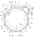
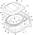
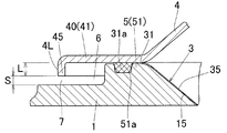
図1はこの発明の実施形態である腹板取付構造が適用可能なガスメータのケース本体1を示す正面図、図2は実施形態の腹板取付構造を説明するための分解斜視図、図3は図1のB−B線断面に相当する断面図である。
FIG. 1 is a front view showing a
なお図1においては、発明の理解を容易にするため、ケース本体1に取り付けられる予定の腹板4の輪郭線4Lを想像線(二点鎖線)で示している。
In FIG. 1, for easy understanding of the invention, the
さらに本実施形態のガスメータにおけるケース本体1のガス計量部分において、前側半分の構成は後側半分の構成に対し面対称で実質的に同一の構成を有している。よって本実施形態の説明では、前側半分の構成を詳細に説明し、後側半分の構成については必要に応じて要部のみを説明するものとする。さらに本発明においては、既述した通りケース本体1の計量部分に関しては、前後対称形状であるため、ケース本体1の「前面」を、ケース本体1の「後面」に置き換えることも可能であり、ケース本体1の「前面」を、ケース本体1の「前面および後面」に置き換えることも可能である。
Further, in the gas metering portion of the case
図1〜図3に示すように、ケース本体1は、鋳造加工によって形成された鋳造品(鋳物)によって構成されており、そのケース本体1の前面には、ガスメータ組立状態で計量室として構成される計量室用凹部15が形成されている。さらにケース本体1の前面における計量室用凹部15の右上には、吸排気路の一端開口である吸排気口2が開口されている。
As shown in FIGS. 1-3, the case
ケース本体1の前面における計量室用凹部15の外周縁部および吸排気口2の外周縁部には、腹板取付部5が形成されている。この腹板取付部5は、前方に盛り上がるようにしてケース本体1に対し一体に形成されている。なお本実施形態においては、腹板取付部5のうち、計量室用凹部15の外周縁部に沿って配置される部分を計量室側腹板取付部51と称し、吸排気口2の外周縁部に沿って配置される部分を吸排気口側腹板取付部52と称する。
An abdominal
計量室側腹板取付部51の前面には、周方向に沿って計量室外周溝51aが形成されるとともに、吸排気口側腹板取付部52の前面には、周方向に沿って吸排気口外周溝52aが形成されている。
A measuring chamber outer
さらに腹板取付部5の前面における外周溝51a,52aの外側には、部分的に外方に突出するようにしてねじ止め部55が周方向に適宜間隔をおいて複数形成されている。各ねじ止め部55には、雌ねじが切り込まれたねじ切り孔56が形成されている。
Further, a plurality of screwing
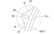
図4は図1の一点鎖線で囲まれた部分を拡大して示す正面図である。同図に示すように本実施形態において、ねじ止め部55の外周面と、ねじ止め部両側の腹板取付部5における外周面との間の入隅部57の曲率半径Rは、10mmに設定されている。参考までに従来のガスメータにおいて対応する入隅部の曲率半径Rは3mm程度であり、本実施形態の入隅部57の曲率半径Rは、大きく滑らかに形成されている。後に詳述するが本実施形態においては、各ねじ止め部55の両側に配置される全ての入隅部57のうち、多くの入隅部57の曲率半径Rが10mmに設定されている。
FIG. 4 is an enlarged front view showing a portion surrounded by a one-dot chain line in FIG. As shown in the figure, in the present embodiment, the radius of curvature R of the
図5は計量膜3を示す図である。図1〜図5に示すようにケース本体1には、計量室用凹部15を閉塞するようにして計量膜3が配置されている。
FIG. 5 is a view showing the
計量膜3は、円盤状の膜本体35と、膜本体35の外周縁部に沿って形成される計量室外周縁部31と、計量室外周縁部31の周方向の一部に、外側に突出するようにして形成され、かつ吸排気口2の外周縁部に沿って配置される吸排気口外周縁部32とを備えている。計量室外周縁部31の裏面側には、ケース本体1の上記計量室外周溝51aに対応し、かつOリングとして機能する計量室外周シール部材31aが設けられている。さらに吸排気口外周縁部32の裏面側には、ケース本体1の上記吸排気口外周溝52aに対応し、かつOリングとして機能する吸排気口外周シール部材32aが設けられている。
The measuring
この計量膜3のシール部材31a,32aがケース本体1の外周溝51a,52aに対応して配置されるようにして、計量膜3の外周縁部31,32がケース本体1の腹板取付部5上に配置される。
The sealing
図2および図3に示すように、腹板4は、ケース本体1の前面側における所領領域のほぼ全域をカバーできる形状に形成されており、その外周縁部には、ケース本体1の腹板取付部5に対応し、かつ腹板取付部5に載置可能な外周取付部40が形成されている。さらに腹板4の外周取付部40のさらに外側、つまり腹板4の外周端縁には、その外周端縁が裏面側に折り曲げられるようにして縁曲げ部45(図3参照)が形成されている。
As shown in FIGS. 2 and 3, the
また腹板4の外周取付部40には、ケース本体1の各ねじ切り孔56に対応して、ねじ挿通孔46がそれぞれ形成されている。
Further, screw insertion holes 46 are formed in the outer peripheral mounting
なお本実施形態においては図2に示すように、腹板4の外周取付部40のうち、ケース本体1の計量室側腹板取付部51に対応する部分が計量室側外周取付部41として構成されるとともに、吸排気口側腹板取付部52に対応する部分が吸排気口側外周取付部47として構成されている。
In the present embodiment, as shown in FIG. 2, the portion corresponding to the measuring chamber side belly
この腹板4によってケース本体1の計量室用凹部15および吸排気口2が計量膜3を介して覆われるようにして、腹板4の外周取付部40がケース本体1の腹板取付部5に載置され、その状態で腹板4のねじ挿通孔46に挿通されたねじ(図示省略)がケース本体1のねじ切り孔56にねじ込まれて固定される。これにより腹板4がケース本体1に締結固定されるとともに、計量膜3がその計量室外周縁部31および吸排気口外周縁部32がケース本体1および腹板4に挟持されて固定される。さらに計量膜3の計量室外周シール部材31aおよび吸排気口外周シール部材32aがケース本体1の計量室外周溝51aおよび吸排気口外周溝52a内に圧縮状態に圧入されて、ケース本体1および腹板4間における計量膜3の外周縁部31,32周辺の気密性が確保される。
The
この腹板取付構造においては図3に示すように、腹板4の縁曲げ部45の先端とケース本体1の表面との間の隙間(腹板外周端縁隙間)7の間隔Sが1.5mmに設定されている。ここで例えば図6および図7に示す従来のガスメータにおける腹板外周端縁隙間96の間隔Sは0.5mm程度に設定されており、実施形態の腹板外周端縁隙間Sは従来の腹板外周端縁隙間96に比べて幅広に設定されている。
In this belly plate mounting structure, as shown in FIG. 3, the gap S between the tip of the edge
なお本実施形態においては、腹板4の縁曲げ部45の長さLは2.5mmに設定されており、従来の腹板の縁曲げ部の長さよりも短く設定されている。このように本実施形態においては縁曲げ部45の長さLを短く設定することにより、腹板外周端縁隙間7の間隔Sを広くするようにしている。
In this embodiment, the length L of the edge
一方、本実施形態においては、ケース本体1の計量室用凹部15と計量膜3とによって囲まれた空間部が、内側計量室として構成されるとともに、計量膜3と腹板4とによって囲まれた空間部が、外側計量室として構成されている。
On the other hand, in the present embodiment, the space surrounded by the
以上の構成の本実施形態のガスメータにおいては、腹板外周端縁隙間7を広く設定しているため、使用期限経過後(使用済)のガスメータを点検する際等に、ショットブラストによってガスメータの表面塗装を剥がした際に、ショットブラストのショット玉(投射材、ブラスト)が腹板外周縁部裏面側の空間部6に侵入するものの、その侵入したショット玉は、腹板外周端縁隙間7を介して外部にスムーズに排出される。このためショットブラストによるショット玉が、腹板外周縁部裏面側の空間部6内に蓄積されることがなく、蓄積されたショット玉を除去する等の面倒な作業が必要なく、その分、ガスメータの点検作業や修繕作業を簡単に行うことができる。
In the gas meter of the present embodiment having the above configuration, the outer
本実施形態において、腹板裏面側の空間部6内に侵入したショット玉は基本的には、自重によって腹板外周端縁隙間7を通って自然に排出されるが、排出が不十分と考えられる場合には必要に応じて空間部6内にエアーブローを併用することによって、空間部6内に侵入したショット玉を吹き飛ばしてより確実に外部に排出することができる。
In this embodiment, the shot ball that has entered the
ここで本実施形態においては、空間部6内に侵入したショット玉を腹板外周端縁隙間7から確実に排出させるためには、腹板外周端縁隙間7の間隔Sを1.0mm以上に設定する必要がある。
Here, in the present embodiment, in order to reliably discharge shot balls that have entered the
なおガスメータの表面処理用のショットブラストで使用されるショット玉の最大径は1mm程度であるが、本実施形態においては、腹板外周端縁隙間7をショット玉の最大径(1mm)よりも大きい1.5mmに設定しているため、全てのショット玉が不具合なく腹板外周端縁隙間7を通過することが可能となる。従って腹板裏面側の空間部6内に侵入したショット玉の腹板外周端縁隙間7からの排出をより一層確実に行うことができ、ショット玉が腹板裏面側に蓄積されるのをより一層確実に防止することができる。言うまでもなく本発明において採用されるショットブラストのショット玉は球体に限られず、どのような形状のものであっても良い。
The maximum diameter of shot balls used in shot blasting for gas meter surface treatment is about 1 mm, but in this embodiment, the abdominal plate outer
また本実施形態の腹板取付構造においては、従来の腹板取付構造と比較して、腹板4における縁曲げ部45の長さLを短くするだけで簡単に形成することができる。このため本実施形態の腹板取付構造が適用されるガスメータは、従来のガスメータに対し大規模な設計変更等を行うことがなく簡単に実現できて、既存のガスメータ部品をほぼそのまま有効利用することができる。
Moreover, in the abdominal plate attachment structure of this embodiment, compared with the conventional abdominal plate attachment structure, it can form simply by shortening the length L of the
さらに本実施形態のガスメータにおいては、腹板4の縁曲げ部45を短くしているため、余分な材料(駄肉)を省略することができて、使用材料およびコストの削減を図ることができるとともに、ガスメータの軽量化を図ることができる。
Furthermore, in the gas meter of this embodiment, since the
ここで本実施形態においては、縁曲げ部45の長さLを3.0mm以下に設定するのが好ましく、それによって腹板外周端縁隙間7の間隔Sを上記の特定値に確実に設定することができる。
Here, in the present embodiment, it is preferable to set the length L of the edge
また本実施形態では、腹板裏面側の空間部6内においてねじ止め部両側の入隅部57の曲率半径Rを大きく滑らかに形成しているため、その入隅部57に滞留しようとするショット玉は自重やエアーブロー等によって流出させることができ、ショット玉を腹板裏面側空間部6から外部により一層スムーズに排出することができる。
Further, in this embodiment, since the radius of curvature R of the
ここで本実施形態においては、ショット玉の滞留防止を有効に行うために、入隅部57の曲率半径Rを4mm以上に形成するのが良く、より好ましくは10mm以上に設定するのが良い。
Here, in the present embodiment, in order to effectively prevent the stay of shot balls, the radius of curvature R of the
また本実施形態においては、ねじ止め部両側に設けられる全ての入隅部57の曲率半径Rを必ずしも上記の特定値以上に形成する必要はないが、入隅部57のうち、少なくともショット玉が滞留し易い入隅部57の曲率半径Rを上記の特定値以上に形成するのが好ましい。本実施形態においてショット玉が滞留し易い入隅部57とは例えば、腹板取付部5の全周のうち上側半周に配置される入隅部57等を挙げることができる。もっとも本発明においては、そっと玉が滞留し易い入隅部57は、過去のデータや実験、研究等によって適宜決定すれば良い。
In the present embodiment, it is not always necessary to form the curvature radius R of all the
別の観点から捉えると、本実施形態においてショット玉の滞留防止効果をより確実に得るためには、全てのねじ止め部57の両側に形成される入隅部57のうち、半分(50%)以上の入隅部57、より好ましくは80%以上の入隅部57の曲率半径Rを上記の特定値以上に形成するのが良い。
From another point of view, in this embodiment, in order to more reliably obtain the effect of preventing the stay of shot balls, half (50%) of the
なお、本実施形態においては、既述した通りケース本体1の前部に内外2つの対をなす計量室が設けられるとともに、後部にも前部と同様に内外2つの対をなす計量室が設けられ、計4つの計量室が前後に並んで設けられている。さらにケース本体1にはその上部を覆うように上ケースが取り付けられる。この上ケース内は、流入室と流出室とに仕切られており、流入室に対応してガス流入口が形成されるとともに、流出室に対応してガス流出口が形成されている。そしてメータ外部からガス流入口を通って上ケースの流入室に導入されたガスは、各計量室に順次導入されて順次計量された後、上ケースの流出室に順次導入され、さらにそのガスがガス流出口を通ってメータ外部に排出されるようになっている。
In the present embodiment, as described above, two pairs of inner and outer measuring chambers are provided at the front of the
ところで、上記実施形態においては、本発明の腹板取付構造をケース本体の前面側に適用する場合を例に挙げて説明したが、それだけに限られず、本発明の腹板取付構造は、ケース本体の後面側にも上記と同様に採用することができる。さらに本発明の腹板取付構造は、ケース本体の前面側および後面側の双方に採用しても良いし、いずれか一方のみに採用するようにしても良い。 By the way, in the said embodiment, although the case where the abdominal plate attachment structure of this invention was applied to the front side of the case main body was mentioned as an example and demonstrated, it is not restricted to it, The abdominal plate attachment structure of this invention is the case main body. The same can be applied to the rear side as well. Furthermore, the abdominal plate attachment structure of the present invention may be employed on both the front side and the rear side of the case body, or may be employed on only one of them.
この発明のガスメータの腹板取付構造は、ガス圧で作動するメカニカル方式のガスメータに好適に採用することができる。 The abdominal plate mounting structure of the gas meter of the present invention can be suitably employed for a mechanical type gas meter that operates by gas pressure.
1:ケース本体
15:計量室用凹部
4:腹板
40:外周縁部
45:縁曲げ部
4L:輪郭線
5:腹板取付部
5L:外側輪郭線
55:ねじ止め部
57:入隅部
7:隙間
L:縁曲げ部の長さ
R:入隅部の曲率半径
S:隙間の間隔
1: Case body 15: Measuring chamber recess 4: Abdominal plate 40: Outer peripheral edge portion 45:
Claims (4)
前記腹板の縁曲げ部の先端と前記ケース本体の表面との間に設けられた隙間の間隔が1.0mm以上に設定されていることを特徴とするガスメータの腹板取付構造。 A case main body provided with a concave portion for the measurement chamber is provided on the front surface, and an abdominal plate mounting portion that protrudes forward is formed on the outer peripheral edge of the concave portion for the measurement chamber in the case main body. A gas meter in which a belly plate is attached so as to cover the concave portion for the measuring chamber from the front side, and an edge bent portion is formed on the outer peripheral edge of the belly plate so that the outer peripheral edge is bent to the back side. The abdominal plate mounting structure of
An abdominal plate mounting structure for a gas meter, wherein a gap provided between a distal end of a bent portion of the abdominal plate and a surface of the case body is set to 1.0 mm or more.
前記ねじ止め部の外周面と、そのねじ止め部の両側における前記腹板取付部の外周面との間の入隅部の曲率半径が4.0mm以上に設定されている請求項1〜3のいずれか1項に記載のガスメータの腹板取付構造。
A plurality of screwing portions are formed at intervals in the circumferential direction so as to protrude outwardly on the outer peripheral surface of the abdominal plate mounting portion,
The curvature radius of the corner part between the outer peripheral surface of the screwing portion and the outer peripheral surface of the belly plate mounting portion on both sides of the screwing portion is set to 4.0 mm or more. The gas meter belly plate mounting structure according to any one of the preceding claims.
Priority Applications (1)
| Application Number | Priority Date | Filing Date | Title |
|---|---|---|---|
| JP2016138432A JP6775184B2 (en) | 2016-07-13 | 2016-07-13 | Gas meter belly plate mounting structure |
Applications Claiming Priority (1)
| Application Number | Priority Date | Filing Date | Title |
|---|---|---|---|
| JP2016138432A JP6775184B2 (en) | 2016-07-13 | 2016-07-13 | Gas meter belly plate mounting structure |
Publications (2)
| Publication Number | Publication Date |
|---|---|
| JP2018009860A true JP2018009860A (en) | 2018-01-18 |
| JP6775184B2 JP6775184B2 (en) | 2020-10-28 |
Family
ID=60995375
Family Applications (1)
| Application Number | Title | Priority Date | Filing Date |
|---|---|---|---|
| JP2016138432A Active JP6775184B2 (en) | 2016-07-13 | 2016-07-13 | Gas meter belly plate mounting structure |
Country Status (1)
| Country | Link |
|---|---|
| JP (1) | JP6775184B2 (en) |
Citations (5)
| Publication number | Priority date | Publication date | Assignee | Title |
|---|---|---|---|---|
| US4091668A (en) * | 1977-03-11 | 1978-05-30 | Kimmon Manufacturing Co., Ltd. | Diaphragm type gas meter |
| JPH029830U (en) * | 1988-07-05 | 1990-01-22 | ||
| JPH0454416A (en) * | 1990-06-22 | 1992-02-21 | Toyo Gasumeetaa Kk | Gas meter equipped with valve freeze resetting function |
| JP2006177805A (en) * | 2004-12-22 | 2006-07-06 | Kimmon Mfg Co Ltd | Membrane gas meter |
| EP3002565A1 (en) * | 2012-01-30 | 2016-04-06 | Pietro Fiorentini S.P.A. | Gas meter |
-
2016
- 2016-07-13 JP JP2016138432A patent/JP6775184B2/en active Active
Patent Citations (5)
| Publication number | Priority date | Publication date | Assignee | Title |
|---|---|---|---|---|
| US4091668A (en) * | 1977-03-11 | 1978-05-30 | Kimmon Manufacturing Co., Ltd. | Diaphragm type gas meter |
| JPH029830U (en) * | 1988-07-05 | 1990-01-22 | ||
| JPH0454416A (en) * | 1990-06-22 | 1992-02-21 | Toyo Gasumeetaa Kk | Gas meter equipped with valve freeze resetting function |
| JP2006177805A (en) * | 2004-12-22 | 2006-07-06 | Kimmon Mfg Co Ltd | Membrane gas meter |
| EP3002565A1 (en) * | 2012-01-30 | 2016-04-06 | Pietro Fiorentini S.P.A. | Gas meter |
Also Published As
| Publication number | Publication date |
|---|---|
| JP6775184B2 (en) | 2020-10-28 |
Similar Documents
| Publication | Publication Date | Title |
|---|---|---|
| US6282951B1 (en) | Fluid flow system having a stress relief casing | |
| ES2453642T3 (en) | Fluid flow meter | |
| CN104225741A (en) | Gas pressure measuring system for a ventilation apparatus of a patient | |
| JP6477195B2 (en) | Flow measuring device | |
| JP2018009860A (en) | Gas meter belly plate mounting structure | |
| US10859418B2 (en) | Airflow measuring device | |
| JP6306434B2 (en) | Ultrasonic flow meter | |
| US10208717B2 (en) | Intake apparatus and dump truck | |
| JP2022084957A (en) | Physical quantity measuring device | |
| Minami et al. | Experimental study on cavitation in centrifugal pump impellers | |
| JP6448467B2 (en) | Ultrasonic flow meter | |
| JP7034480B2 (en) | Fluid pressure detector | |
| JP2005283565A (en) | Flow measuring device | |
| EP3583897A1 (en) | Breath measurement device | |
| JP2016138857A (en) | Fitting structure for gas meter and case body | |
| US20210164424A1 (en) | Air cleaner | |
| WO2016180026A1 (en) | Moisture-proof balance | |
| JP2015099040A (en) | Probe measuring device and correction method | |
| US10684155B2 (en) | Air flow rate measurement device | |
| WO2021214694A1 (en) | Mask | |
| CN108036891A (en) | A kind of baroceptor safeguard structure, barometer and unmanned plane | |
| CN107850079A (en) | Pump | |
| US20190265148A1 (en) | Fluid sensor | |
| JP3921518B2 (en) | Pulsation absorption structure of electronic gas meter | |
| CN110397571A (en) | Noise reduction device with gas pulsation disturbing effect and compressor |
Legal Events
| Date | Code | Title | Description |
|---|---|---|---|
| A621 | Written request for application examination |
Free format text: JAPANESE INTERMEDIATE CODE: A621 Effective date: 20190617 |
|
| A131 | Notification of reasons for refusal |
Free format text: JAPANESE INTERMEDIATE CODE: A131 Effective date: 20200623 |
|
| A521 | Request for written amendment filed |
Free format text: JAPANESE INTERMEDIATE CODE: A523 Effective date: 20200807 |
|
| TRDD | Decision of grant or rejection written | ||
| A01 | Written decision to grant a patent or to grant a registration (utility model) |
Free format text: JAPANESE INTERMEDIATE CODE: A01 Effective date: 20200901 |
|
| A61 | First payment of annual fees (during grant procedure) |
Free format text: JAPANESE INTERMEDIATE CODE: A61 Effective date: 20200918 |
|
| R150 | Certificate of patent or registration of utility model |
Ref document number: 6775184 Country of ref document: JP Free format text: JAPANESE INTERMEDIATE CODE: R150 |
|
| RD02 | Notification of acceptance of power of attorney |
Free format text: JAPANESE INTERMEDIATE CODE: R3D02 |
|
| R250 | Receipt of annual fees |
Free format text: JAPANESE INTERMEDIATE CODE: R250 |