JP2018009859A - Gas analyzer - Google Patents
Gas analyzer Download PDFInfo
- Publication number
- JP2018009859A JP2018009859A JP2016138353A JP2016138353A JP2018009859A JP 2018009859 A JP2018009859 A JP 2018009859A JP 2016138353 A JP2016138353 A JP 2016138353A JP 2016138353 A JP2016138353 A JP 2016138353A JP 2018009859 A JP2018009859 A JP 2018009859A
- Authority
- JP
- Japan
- Prior art keywords
- hole
- gas
- cylinder
- light receiving
- analysis target
- Prior art date
- Legal status (The legal status is an assumption and is not a legal conclusion. Google has not performed a legal analysis and makes no representation as to the accuracy of the status listed.)
- Granted
Links
Images
Landscapes
- Investigating Or Analysing Materials By Optical Means (AREA)
Abstract
【課題】分析対象ガス中のミストまたはダストによる影響を軽減する。【解決手段】煙道内を流れる分析対象ガスに対してレーザー光を照射する照射部と、煙道を挟むように照射部と対向して配置されて、分析対象ガスを通過したレーザー光を受光する受光部と、レーザー光が内部を通過するように照射部と受光部との間に配置され、煙道内において、分析対象ガスの上流側に面する第1孔と分析対象ガスの下流側に面する第2孔とが形成された一体の筒と、を備えるガス分析装置を提供する。【選択図】図1An object of the present invention is to reduce the influence of mist or dust in an analysis target gas. An irradiation unit that irradiates a laser beam to an analysis target gas flowing in a flue, and an irradiation unit that is arranged to face the irradiation unit so as to sandwich the flue, receives the laser light that has passed through the analysis target gas. a light receiving part, a first hole disposed between the irradiation part and the light receiving part so that the laser light passes through the interior, and a first hole facing the upstream side of the gas to be analyzed and a surface facing the downstream side of the gas to be analyzed in the flue and an integrated cylinder having a second hole formed therein. [Selection drawing] Fig. 1
Description
本発明は、ガス分析装置に関する。 The present invention relates to a gas analyzer.
従来、レーザー式のガス分析装置が知られている。ガス分析装置は、レーザー光を分析対象ガスに照射する照射部と、分析対象ガスを通過したレーザー光を受光する受光部とを備える。ガス分析装置は、受光部での受光量に基づいて吸収スペクトルを分析する。ガス分析装置は、吸収スペクトルに基づいて、分析対象ガス中の対象物質の濃度を分析する(例えば、特許文献1参照)。
[先行技術文献]
[特許文献]
[特許文献1] 特開2009−270917号公報
Conventionally, a laser-type gas analyzer is known. The gas analyzer includes an irradiation unit that irradiates the analysis target gas with laser light, and a light receiving unit that receives the laser light that has passed through the analysis target gas. The gas analyzer analyzes the absorption spectrum based on the amount of light received by the light receiving unit. The gas analyzer analyzes the concentration of the target substance in the analysis target gas based on the absorption spectrum (see, for example, Patent Document 1).
[Prior art documents]
[Patent Literature]
[Patent Document 1] Japanese Patent Application Laid-Open No. 2009-270917
レーザー式ガス分析装置において、分析対象ガス中にミストまたはダストが含まれる場合、レーザー光がミストまたはダストによって散乱または吸収される。ミストまたはダストの量によっては、受光部におけるレーザー光の受光量が減少し、対象物質の濃度の測定が困難になる場合がある。 In the laser type gas analyzer, when the gas to be analyzed contains mist or dust, the laser light is scattered or absorbed by the mist or dust. Depending on the amount of mist or dust, the amount of laser light received by the light receiving unit may decrease, making it difficult to measure the concentration of the target substance.
本発明の一つの態様においては、ガス分析装置は、照射部と、受光部と、筒とを備えてよい。照射部は、煙道内を流れる分析対象ガスに対してレーザー光を照射してよい。受光部は、煙道を挟むように照射部と対向して配置されてよい。受光部は、分析対象ガスを通過したレーザー光を受光してよい。筒は、レーザー光が内部を通過するように照射部と受光部との間に配置された一体の筒であってよい。筒は、煙道内において、第1孔と第2孔とが形成されてよい。第1孔は、分析対象ガスの上流側に面してよい。第2孔は、分析対象ガスの下流側に面してよい。 In one aspect of the present invention, the gas analyzer may include an irradiation unit, a light receiving unit, and a tube. The irradiation unit may irradiate the analysis target gas flowing in the flue with laser light. The light receiving unit may be arranged to face the irradiation unit so as to sandwich the flue. The light receiving unit may receive laser light that has passed through the analysis target gas. The cylinder may be an integral cylinder arranged between the irradiation unit and the light receiving unit so that the laser beam passes through the inside. The tube may be formed with a first hole and a second hole in the flue. The first hole may face the upstream side of the analysis target gas. The second hole may face the downstream side of the analysis target gas.
ガス分析装置は、照射部側導入部と受光部側導入部とを備えてよい。照射部側導入部は、筒の照射部側の端部からパージガスを筒内に導入してよい。受光部側導入部は、筒の受光部側の端部からパージガスを筒内に導入してよい。 The gas analyzer may include an irradiation unit side introduction unit and a light receiving unit side introduction unit. The irradiation unit side introduction unit may introduce purge gas into the cylinder from the end of the cylinder on the irradiation unit side. The light receiving unit side introduction unit may introduce purge gas into the cylinder from the end of the cylinder on the light receiving unit side.
第2孔は、第1孔と対向するように分析対象ガスの下流側に配置されて開口面積が第1孔より大きくてよい。 The second hole may be disposed on the downstream side of the analysis target gas so as to face the first hole, and the opening area may be larger than that of the first hole.
第1孔及び第2孔は、長軸を有してよい。長軸は、筒の長手方向に伸びてよい。 The first hole and the second hole may have a long axis. The long axis may extend in the longitudinal direction of the cylinder.
ガス分析装置は、カバー部を更に備えてよい。カバー部は、筒と離れて形成されてよい。カバー部は、第1孔を部分的に覆ってよい。 The gas analyzer may further include a cover part. The cover part may be formed apart from the cylinder. The cover part may partially cover the first hole.
カバー部は、第1孔の長軸方向における中央部を覆っていてよい。カバー部は、第1孔の長軸方向における端部を覆っていなくてよい。第1孔は、筒の長手方向に伸びる長軸を有してよい。 The cover part may cover the center part in the major axis direction of the first hole. The cover part does not need to cover the end part in the major axis direction of the first hole. The first hole may have a long axis extending in the longitudinal direction of the cylinder.
カバー部は、孔部が形成されてよい。孔部は、分析対象ガスを通過させてよい。 The cover portion may be formed with a hole. The analysis target gas may be passed through the hole.
カバー部は、第1孔の全体を覆っていてよい。カバー部は、孔部が形成されていてよい。 The cover part may cover the entire first hole. The cover portion may have a hole.
カバー部は、孔部が複数形成されていてよい。 The cover portion may have a plurality of holes.
カバー部は、複数に分割されていてよい。 The cover part may be divided | segmented into plurality.
カバー部の下端は、第1孔より下側まで延伸してよい。 The lower end of the cover part may extend from the first hole to the lower side.
なお、上記の発明の概要は、本発明の必要な特徴の全てを列挙したものではない。また、これらの特徴群のサブコンビネーションもまた、発明となりうる。 It should be noted that the above summary of the invention does not enumerate all the necessary features of the present invention. In addition, a sub-combination of these feature groups can also be an invention.
以下、発明の実施の形態を通じて本発明を説明するが、以下の実施形態は特許請求の範囲にかかる発明を限定するものではない。また、実施形態の中で説明されている特徴の組み合わせの全てが発明の解決手段に必須であるとは限らない。 Hereinafter, the present invention will be described through embodiments of the invention, but the following embodiments do not limit the invention according to the claims. In addition, not all the combinations of features described in the embodiments are essential for the solving means of the invention.
本明細書では、X軸、Y軸およびZ軸の直交座標軸を用いて技術的事項を説明する。直交座標軸は、構成要素の相対位置を特定するに過ぎず、特定の方向を限定するものではない。例えば、Z軸は地面に対する高さ方向を限定して示すものではない。なお、+Z軸方向と−Z軸方向とは互いに逆向きの方向である。正負を記載せず、Z軸方向と記載した場合、+Z軸および−Z軸に平行な方向を意味する。 In this specification, technical matters will be described using orthogonal coordinate axes of the X axis, the Y axis, and the Z axis. The Cartesian coordinate axis only specifies the relative position of the component, and does not limit a specific direction. For example, the Z axis does not limit the height direction with respect to the ground. Note that the + Z-axis direction and the −Z-axis direction are directions opposite to each other. When the Z axis direction is described without describing positive and negative, it means a direction parallel to the + Z axis and the −Z axis.
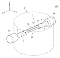
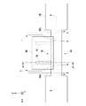
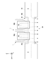
図1は、本発明の第1実施形態におけるガス分析装置100の概要を示す斜視図である。ガス分析装置100は、煙道60内を流れる分析対象ガス1を分析する。本例では、分析対象ガス1は、Z軸方向に流れる。煙道60は、ボイラまたは燃焼炉から排出されるガスの流路であってよい。ボイラまたは燃焼炉は、石炭、重油、またはごみを燃焼してよい。但し、煙道60は、ガス流路に限られない。本明細書における煙道60は、分析対象ガス1が流れる内部空間を含む機器であればよく、容器、煙突、排気ダクト、脱硝装置、化学プラント設備、鉄鋼プラント設備、および加熱炉等の各種機器であってよい。
FIG. 1 is a perspective view showing an outline of a
ガス分析装置100は、測定用のガスを煙道60外部に抽出不要な直接挿入式のレーザー式ガス分析計であってよい。ガス分析装置100は、照射部10および受光部20を備える。照射部10および受光部20は、煙道60の外部に配置される。照射部10と受光部20とは、煙道60を挟むように対向して配置される。本例では、照射部10と受光部20とは、X軸方向に沿って配置される。照射部10は、煙道60内を流れる分析対象ガス1に対してレーザー光2を照射する。受光部20は、分析対象ガス1を通過したレーザー光2を受光する。
The
本例のガス分析装置100は、照射部10と受光部20との間に配置された一体の筒30を備える。一体の筒30とは、照射部10と受光部20との間を連結する管状体を意味する。一体の筒30は、照射部10と受光部20との間で分断していない限り、複数の筒が継ぎ合わされて構成されてよい。筒30は、レーザー光2が内部を通過するように配置される。本例の筒30は、長手方向がX軸方向に平行するように配置される。レーザー光2が筒30の内壁によって干渉されないためには、レーザー光2が筒30の中心軸付近を通過することが好ましい。
The
筒30の管壁には、第1孔32および第2孔34が形成されている。第1孔32は、分析対象ガス1の上流側に面する。一方、第2孔34は、分析対象ガス1の下流側に面する。第2孔34は、第1孔32と対向する位置に設けられる。分析対象ガス1は、第1孔32から流入して第2孔34から流出する。したがって、第1孔32と第2孔34に挟まれた空間領域は、分析対象ガス雰囲気に晒される。第1孔32と第2孔34に挟まれた空間領域において、レーザー光2は、分析対象ガス1を通過する。なお、分析対象ガス1が照射部10側および受光部20側に流入しないように、筒30のX軸方向における両端から中央に向かってパージガス6およびパージガス8が筒30内に導入されてよい。
A
ガス分析装置100は、受光部20による受光量に基づいて吸収スペクトルを分析する。ガス分析装置100は、吸収スペクトルから、分析対象ガス1中に含まれる対象物質の濃度を分析する。対象物質は、HCl、NH3、O2、CO、CO2、HF、CH4、NOXおよびH2Oなどのガス成分であってよい。本明細書において分析対象ガス1は、特に限定されない。分析対象ガス1は、乾留ガス、発生ガス、排気ガス、鉄鋼プラントガス、プロセスガス、および炉内ガスなどの各種ガスであってよい。
The
ガス分析装置100は、特定の波長におけるレーザー光2の減衰量に基づいて対象物質の濃度を分析してよい。具体的には、ランベルト・ベール(Lambert‐Beer)の法則により、レーザー光2の減衰量は、対象物質の濃度とその物質が存在する領域の測定光路長とに依存する。ランベルト・ベールの式を[数1]に示す。本例では、測定光路長Lsが、第1孔32のX軸方向における長さによって規定される。ガス分析装置100による処理自体は、従来のレーザー式ガス分析装置と同様であるので、詳しい説明は省略する。
The
[数1]
I(L)=I(O)・exp[−ks・ns・Ls]
ここで、I(L)は、受光量である。
I(O)は、照射光量(発光量)である。
ksは、ガス係数である。
nsは、対象物質の濃度(vol/%)である。
Lsは、測定光路長である。
[Equation 1]
I (L) = I (O) · exp [−ks · ns · Ls]
Here, I (L) is the amount of received light.
I (O) is an irradiation light amount (light emission amount).
ks is a gas coefficient.
ns is the concentration (vol /%) of the target substance.
Ls is the measurement optical path length.
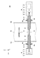
図2は、本発明の第1実施形態におけるガス分析装置100の断面図である。図2においては、煙道60に取り付けられた状態のガス分析装置100を示している。本例では、煙道60は、Z軸方向に伸びる円筒管状に形成されているが、煙道60の形状は、この場合に限定されない。ガス分析装置100が取り付けられる煙道60は、0.5m以上の煙道幅を有してよい。一例では、煙道幅は、2m以上20m以下である。煙道幅は、分析対象ガス1の流れの方向に垂直な方向の煙道の側壁間の間隔であってよい。
FIG. 2 is a cross-sectional view of the
煙道60において、互いに対向する側壁62aおよび側壁62bの各部分に孔が形成されている。側壁62aおよび側壁62bは、それぞれ照射部10側および受光部20側の側壁である。側壁62aおよび側壁62bに形成された孔に筒30が挿入されて、筒30が煙道60に固定されてよい。筒30は、防食性の観点から、ステンレスで形成されてよい。但し、筒30の材質は限定されない。筒30の内径は、筒30の中を通過するレーザー光2が筒30の内側面と干渉しない程度に大きく、筒30内を流れるパージガス6、8の流速が低くなりすぎない程度に小さくてよい。一例では、筒30の内径は、1cm以上5cm以下である。
In the
筒30は、煙道60の側壁62aおよび側壁62bから煙道60の外部に突出する。筒30は、照射部10側の突出部分にフランジ36aを備えてよい。フランジ36aと照射部10との間には、照射部側連結管30aが設けられてよい。本例の照射部側連結管30aには、フランジ37aが設けられている。本例では、フランジ36aとフランジ37aを連結することで、筒30と照射部側連結管30aとが連通する。
The
筒30は、受光部20側の部分においても、照射部10側の部分と同様の構成を有してよい。具体的には、筒30は、受光部20側の突出部分にフランジ36bを備えてよい。フランジ36bと受光部20との間には、受光部側連結管30bが設けられてよい。本例では、フランジ36bとフランジ37bを連結することで、筒30と受光部側連結管30bとが連通する。なお、照射部側連結管30a、フランジ37a、フランジ36a、筒30、フランジ36b、フランジ37b、および受光部側連結管30bは、この並び順で、照射部10と受光部20との間を連結する管状体を構成しているので、これら全体が一体の筒を構成しているといえる。
The
以上のようにフランジ36(36a、36b)およびフランジ37(37a、37b)を用いることによって、筒30の煙道60への取り付けと、フランジ37を介する照射部10および受光部20の取り付けとを別々に施工することができる。したがって、本例のガス分析装置100を煙道60に取り付けやすくなる。但し、ガス分析装置100は、この場合に限られず、筒30が直接的に照射部10および受光部20に接続されてもよい。
As described above, by using the flange 36 (36a, 36b) and the flange 37 (37a, 37b), the attachment of the
照射部10は、レーザー素子12、コリメートレンズ14、筐体16、および照射部側透光窓18を含む。レーザー素子12は、分布帰還型(DFB)レーザーであってもよく、垂直共振器面発光レーザー(Vertical Cavity Surface Emitting LASER)であってもよい。レーザー素子12は、出力するレーザー光2の波長を変更可能な波長可変レーザー素子であってよい。コリメートレンズ14は、レーザー素子12から出射されたレーザー光2を平行光線とする。
The
筐体16は、内部に、レーザー素子12およびコリメートレンズ14を格納する。筐体16の一部には、照射部側透光窓18が設けられている。コリメートレンズ14を通過したレーザー光2は、照射部側透光窓18を通過して筐体16の外部へ進む。照射部側透光窓18は、レーザー光2の光軸に対する垂直面から傾いて設けられてよい。照射部側透光窓18を囲むように、照射部側連結管30aが筐体16に固定される。照射部側連結管30aの端部は、照射部側透光窓18および筐体16によって封止されてよい。
The
受光部20は、集光レンズ22、受光素子24、信号処理部25、筐体26、および受光部側透光窓28を含む。集光レンズ22は、分析対象ガス1を通過したレーザー光2を受光素子24に集光する。受光素子24は、受光量に応じて電気信号を出力する素子である。例えば、受光素子24は、フォトダイオードまたはフォトトランジスタを有する。受光素子24は、受光量に応じた電流を出力してよい。信号処理部25は、受光素子24からの電流を受けて電圧に変換してよい。信号処理部25は、変換された電圧を検波およびフィルタ処理して、ノイズが除去された信号を生成してよい。信号処理部25は、ノイズが除去された信号を用いて、対象物質の濃度を算出してよい。
The
筐体26は、内部に、集光レンズ22、受光素子24、および信号処理部25を格納する。筐体26の一部には、受光部側透光窓28が設けられている。受光部側透光窓28を通過したレーザー光2が筐体26内に入射する。受光部側透光窓28は、レーザー光2の光軸に対する垂直面から傾いて設けられてよい。受光部側透光窓28を囲むように、受光部側連結管30bが筐体26に固定される。受光部側連結管30bの端部は、受光部側透光窓28および筐体26によって封止されてよい。
The
ガス分析装置100は、パージガス6、8を導入するための照射部側導入部42および受光部側導入部44を備える。照射部側導入部42は、筒30の照射部10側の端部からパージガス6を筒30内に導入する。一方、受光部側導入部44は、筒30の受光部20側の端部からパージガス8を筒30内に導入する。パージガス6、8は、空気または窒素ガスであってよい。
The
本明細書において、筒30の照射部10側の端部とは、第1孔32を基準に照射部10側に位置する筒30の領域を意味し、特に、側壁62aと照射部10の間における筒30(あるいは、照射部側連結管30a)の領域を意味する。本明細書において、筒30の受光部20側の端部とは、第1孔32を基準に受光部20側に位置する筒30の領域を意味し、特に、側壁62bと受光部20の間における筒30(あるいは受光部側連結管30b)の領域を意味する。
In this specification, the end of the
照射部側導入部42および受光部側導入部44は、それぞれパージガス流入口であってよい。本例では、照射部側導入部42および受光部側導入部44は、煙道60の外部に設けられる。本例の照射部側導入部42は、照射部側連結管30aに設けられ、本例の受光部側導入部44は、受光部側連結管30bに設けられる。照射部側導入部42から導入されたパージガス6は、筒30内を満たしつつ、煙道60の中央に向かって流れる。同様に、受光部側導入部44から導入されたパージガス8は、煙道60の中央に向かって流れる。パージガス6およびパージガス8は、第2孔34から筒30の外に排出される。
The irradiation part
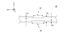
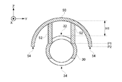
図3は、筒30の側面図である。第2孔34は、第1孔32と対向するように分析対象ガス1の下流側に配置される。第2孔34は、筒30をZ軸方向から見た外形が、第1孔32の外形を包含するように配置されてよい。第2孔34は、開口面積が第1孔32より大きい。このように第1孔32および第2孔34を形成することによって、第1孔32を通過した分析対象ガス1が第2孔34を通過するときの圧力損失を低減することができる。したがって、分析対象ガス1が第2孔34を通過せずに筒30内を照射部10側および受光部20側に流入しにくくすることができる。
FIG. 3 is a side view of the
第1孔32と第2孔34は、X軸方向における中心位置が一致してよく、Y軸方向における中心位置が一致してよい。第1孔32のX軸方向(長軸方向)における長さL1は、第2孔34のX軸方向における長さL2より短くてよい。第1孔32の長軸方向の長さL1は、0.3m以上1m以下であってよい。一例として、長さL1は0.5mである。本例のガス分析装置100において、第1孔32の長軸方向の長さL1に亘る領域が、分析対象ガス1に晒されることとなり、長さL1に応じて測定光路長Lsが定まる。
The
第1孔32は、筒30の表面の切欠きであってよい。筒30をY軸方向から見た場合の第1孔32の切欠きの厚さD2は、一例として、筒30の外径D1の1/4であってよい。第2孔34の切欠きの厚さD3も、筒30の外径D1の1/4であってよい。但し、厚さD3が厚さD2より大きくてもよい。この場合、第2孔34のY軸方向の幅が第1孔32より大きくなり、第1孔32を通過するときの圧力損失を低減できる。
The
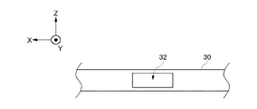
図4は、筒30の上面図である。第1孔32は、長方形状に形成されてよい。但し、本例と異なり、第1孔32は、楕円形に形成されてもよい。第1孔32は、筒30の長手方向(X軸方向)に伸びる長軸を有し、Y軸方向に伸びる短軸を有してよい。第2孔34も、X軸方向に伸びる長軸を持った長方形または楕円形に形成されてよい。第1孔32および第2孔34の長軸が筒30の長手方向に伸びることによって、筒30の径が細い場合であっても、分析感度を維持できる測定光路長Lsを確保することができる。
FIG. 4 is a top view of the
本例のガス分析装置100によれば、分析対象ガス1中に存在するミストおよびダストによる分析結果への影響を軽減することができる。本例では、ミストおよびダストによる影響は、第1孔32および第2孔34によって開口されている領域に限定される。特に、煙道60の幅が大きくて、照射部10と受光部20との距離を大きくとらなければガス分析装置100を設置できない環境であっても、測定光路長Lsを煙道60の幅より短い長さとして、ミストおよびダストの影響を軽減することができる。ミストおよびダストの影響が軽減されるため、ガス分析装置100は、対象物質の濃度を安定して分析することができる。
According to the
本例のガス分析装置100によれば、照射部10から第1孔32に至る領域において筒30内はパージガス6によって満たされる。同様に、受光部20から第1孔32に至る領域において筒30内はパージガス8によって満たされる。したがって、分析対象ガス1は、第1孔32および第2孔34から照射部10側および受光部20側に流入しないので、測定光路長Ls以外の領域におけるレーザー光2の減衰を防止することができる。
According to the
煙道60内の分析対象ガス1の流れの方向(Z軸方向)に整列されるように第1孔32と第2孔34とが配置されるので、分析対象ガス1が効果的に第1孔32から流入し第2孔34から流出する。したがって、筒30内において、測定光路長Lsに対応する領域においては、第1孔32から第2孔34へ向かう方向に分析対象ガス1の流れが生じる。測定光路長Lsに対応する領域においては、パージガス6、8は、分析対象ガス1の流れによってZ軸方向に流されて、第2孔34から排出される。それゆえ、パージガス6、8が測定光路長Lsに対応する領域に深く侵入することが防止される。
Since the
本例のガス分析装置100によれば、筒30は、レーザー光2が内部を通過するように照射部10と受光部20との間に配置された一体の筒であるので、煙道60の照射部10側の側壁62aと受光部20側の側壁62bとの間で両持ち支持される。したがって、筒30が片持ち支持される場合と比べて、筒30の撓みおよび曲りが軽減され、レーザー光2の光軸のずれを防止できる。
According to the
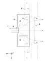
図5は、本発明の第2実施形態におけるガス分析装置100の側面図である。図6は、本発明の第2実施形態におけるガス分析装置100のA‐A´線に沿う断面図である。本例のガス分析装置100は、カバー部50を備える。他の構造は、第1実施形態のガス分析装置100と同様である。カバー部50は、ダストおよびミストの影響を軽減するための庇である。カバー部50は、防食性の観点から、ステンレスで形成されてよい。但し、筒30の材質は限定されない。
FIG. 5 is a side view of the
カバー部50は、筒30と離れて形成される。カバー部50が筒30と離れて形成されるとは、カバー部50と筒30とがZ軸方向に離間して設けられることを意味する。本例では、図6に示されるとおり、筒30の外側面とカバー部50の内側面とはZ軸方向に離間距離H1だけ離れている。一例として、離間距離H1は、筒30の直径以上であってよい。カバー部50は、支持部52を介して筒30に固定されてよい。
The
カバー部50が、筒30と離れて形成されるので、第1孔32が設けられた領域、すなわち測定光路長Lsに対応する領域に分析対象ガス1が拡散によって十分に入り込むことができる。したがって、測定光路長Lsに対応する領域において、対象物質の濃度が本来の濃度と異なってしまうことを防止できる。一方、ダストおよびミストは、対象物質である分子と比べて、粒径が大きくて重い。それゆえ、ダストおよびミストは、対象物質である分子と比べて、拡散しづらいので、第1孔32が設けられた領域に十分に入り込むことが困難である。したがって、カバー部50を設けることによって、ダストおよびミストの影響を軽減しつつ、対象物質の濃度を正確に分析することができる。
Since the
カバー部50の下端54は、第1孔32より下側まで延伸してよい。本例では、分析対象ガス1の上流側を上とし、分析対象ガス1の下流側を下とする。本例では、カバー部50の下端54の位置P2が、第1孔32の切欠きの上面の位置P1より低い。このように、カバー部50の下端54が、第1孔32より下側まで延伸していることによって、カバー部50に積もったダストが第1孔32内に落下することを防止することができる。
The
図5に示されるとおり、本例のカバー部50は、第1孔32の長軸方向(X軸方向)における中央部を覆う。カバー部50は、第1孔32の長軸方向における端部38a、38bを覆っていない。カバー部50が第1孔32の端部38aを覆っていないので、第1孔32の端部38aにおいては、カバー部50によって分析対象ガス1の流れが遮断されず、分析対象ガス1の流れが確保される。したがって、パージガス6は、第1孔32の端部38a付近の分析対象ガス1の流れによってZ軸方向に流されて、第2孔34から排出される。それゆえ、パージガス6が、測定光路長Lsに対応する領域に深く侵入することが防止される。同様に、パージガス8も、測定光路長Lsに対応する領域に深く侵入することが防止される。
As shown in FIG. 5, the
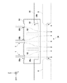
図7は、第2実施形態におけるガス分析装置100の変形例を示す側面図である。本例のガス分析装置100は、カバー部50が第1孔32の全体を覆う。本明細書において、カバー部50が第1孔32の全体を覆うとは、カバー部50のX軸方向の長さが第1孔32のX軸方向の長さより長く、かつ、カバー部50のY軸方向の長さが第1孔32のY軸方向の長さより長いことを意味する。カバー部50には、分析対象ガス1を通過させる孔部56が形成されている。カバー部50の違いを除いて、他の構造は、図5に示されるガス分析装置100と同様である。
FIG. 7 is a side view showing a modification of the
孔部56は、カバー部50のX軸方向における中央部に形成されてよい。本例の孔部56の大きさは、第1孔32のY軸方向の幅より小さい。孔部56の大きさは、ダストおよびミストによって目詰まりしないように定められてよい。
The
本例のガス分析装置100によれば、庇として機能するカバー部50が第1孔32より大きく、カバー部50が第1孔32の全体を覆っている。したがって、ミストおよびダストの影響を更に低減できる。孔部56によって、第1孔32から第2孔34への分析対象ガス1の流れを確保できるので、パージガス6、8が、第1孔32が形成されている領域に深く侵入することが防止される。
According to the
本例のガス分析装置100において、図5に示されるように、カバー部50が、第1孔32の長軸方向における中央部を覆っていて、第1孔32の長軸方向における端部38を覆っていないように形成しつつ、孔部56を設けてもよい。
In the
図8は、第2実施形態におけるガス分析装置100の他の変形例を示す側面図である。本例のガス分析装置100は、カバー部50に、孔部56a、孔部56b、および孔部56cが形成されている。他の構造は、図7に示される例と同様である。複数の孔部56のうち、孔部56bは、カバー部50のX軸方向における中央部に形成される。孔部56aおよび孔部56cは、第1孔32の長軸方向における端部38aおよび端部38bと対向する位置に形成されてよい。但し、カバー部50に形成される複数の孔部の数および位置は、制限されない。カバー部50には、孔部56aと孔部56cが形成され、孔部56bが形成されなくてもよい。
FIG. 8 is a side view showing another modification of the
カバー部50に、孔部56が複数形成されることによって、孔部56が一つの場合と比べて、パージガス6、8が、第1孔32が形成されている領域に深く侵入することを防止しやすい。特に、孔部56aおよび孔部56cが、第1孔32の長軸方向における端部38a、38bと対向する位置に形成されることによって、パージガス6、8が光路測定長L1に対応する領域に深く侵入することを防止しやすい。
By forming a plurality of
第1孔32の端部38aにおいては、カバー部50によって分析対象ガス1の流れが遮断されず、分析対象ガス1の流れを確保できる。したがって、パージガス6は、孔部56aを通過した分析対象ガス1の流れによってZ軸方向に流されて、第2孔34から排出される。それゆえ、パージガス6は、測定光路長Lsに対応する領域に深く侵入しない。同様に、パージガス8も、測定光路長Lsに対応する領域に深く侵入しない。
At the
図9は、第2実施形態におけるガス分析装置100の他の変形例を示す側面図である。本例のガス分析装置100では、カバー部50が、複数のカバー部50a、50bに分割されている。複数のカバー部50aおよびカバー部50bは、予め定められた間隙を開けてX軸方向に沿って配列されてよい。他の構造は、図5に示される例と同様である。隣接する複数のカバー部50a、50bの間の間隙は、分析対象ガス1の流れを遮断せず、孔部56bと同様の機能をはたす。したがって、本変形例によっても、パージガス6およびパージガス8が測定光路長に対応する領域に深く侵入することが防止される。本例では、カバー部50が2つのカバー部50aおよび50bに分割されているが、カバー部50は、3個以上のカバー部に分割されてもよい。
FIG. 9 is a side view showing another modification of the
以上、本発明を実施の形態を用いて説明したが、本発明の技術的範囲は上記実施の形態に記載の範囲には限定されない。各実施形態および各変形例は、相互に組み合わせることができる。上記実施の形態に、多様な変更又は改良を加えることが可能であることが当業者に明らかである。その様な変更又は改良を加えた形態も本発明の技術的範囲に含まれ得ることが、特許請求の範囲の記載から明らかである。 As mentioned above, although this invention was demonstrated using embodiment, the technical scope of this invention is not limited to the range as described in the said embodiment. Each embodiment and each modification can be combined with each other. It will be apparent to those skilled in the art that various modifications or improvements can be added to the above embodiment. It is apparent from the description of the scope of claims that embodiments with such changes or improvements can be included in the technical scope of the present invention.
1・・・分析対象ガス、2・・・レーザー光、6・・・パージガス、8・・・パージガス、10・・・照射部、12・・・レーザー素子、14・・・コリメートレンズ、16・・・筐体、18・・・照射部側透光窓、20・・・受光部、22・・・集光レンズ、24・・・受光素子、25・・・信号処理部、26・・・筐体、28・・・受光部側透光窓、30・・・筒、30a・・・照射部側連結管、30b・・・受光部側連結管、32・・・第1孔、34・・・第2孔、36・・・フランジ、37・・・フランジ、38・・・端部、42・・・照射部側導入部、44・・・受光部側導入部、50・・・カバー部、52・・・支持部、54・・・下端、56・・・孔部、60・・・煙道、62・・・側壁、100・・・ガス分析装置
DESCRIPTION OF
Claims (11)
前記煙道を挟むように前記照射部と対向して配置されて、前記分析対象ガスを通過した前記レーザー光を受光する受光部と、
前記レーザー光が内部を通過するように前記照射部と前記受光部との間に配置され、前記煙道内において、前記分析対象ガスの上流側に面する第1孔と前記分析対象ガスの下流側に面する第2孔とが形成された一体の筒と、を備える
ガス分析装置。 An irradiation unit for irradiating the gas to be analyzed flowing in the flue with laser light;
A light receiving unit that is disposed opposite the irradiation unit so as to sandwich the flue, and that receives the laser light that has passed through the analysis target gas;
A first hole facing the upstream side of the analysis target gas and a downstream side of the analysis target gas in the flue, disposed between the irradiation unit and the light receiving unit so that the laser light passes through the inside A gas analysis apparatus comprising: an integral cylinder formed with a second hole facing the surface.
前記筒の受光部側の端部からパージガスを前記筒内に導入する受光部側導入部と、
を備える請求項1に記載のガス分析装置。 An irradiation part side introduction part for introducing purge gas into the cylinder from an end part on the irradiation part side of the cylinder;
A light receiving part side introduction part for introducing purge gas into the cylinder from an end part on the light receiving part side of the cylinder;
A gas analyzer according to claim 1.
請求項1または2に記載のガス分析装置。 3. The gas analyzer according to claim 1, wherein the second hole is disposed downstream of the analysis target gas so as to face the first hole, and has an opening area larger than the first hole.
請求項1から3の何れか1項に記載のガス分析装置。 4. The gas analyzer according to claim 1, wherein the first hole and the second hole have a long axis extending in a longitudinal direction of the cylinder. 5.
請求項1から4の何れか1項に記載のガス分析装置。 The gas analyzer according to any one of claims 1 to 4, further comprising a cover portion that is formed apart from the cylinder and partially covers the first hole.
請求項5に記載のガス分析装置。 The said cover part has covered the center part in the major axis direction of the said 1st hole which has a long axis extended in the longitudinal direction of the said cylinder, and does not cover the edge part in the major axis direction of the said 1st hole. The gas analyzer described in 1.
請求項5に記載のガス分析装置。 The gas analysis apparatus according to claim 5, wherein the cover part is formed with a hole through which the analysis target gas passes.
請求項7に記載のガス分析装置。 The gas analysis apparatus according to claim 7, wherein the cover portion covers the entire first hole, and the hole portion is formed.
請求項7または8に記載のガス分析装置。 The gas analysis apparatus according to claim 7 or 8, wherein the cover part has a plurality of holes.
請求項5から9の何れか1項に記載のガス分析装置。 The gas analyzer according to claim 5, wherein the cover part is divided into a plurality of parts.
請求項5から10の何れか1項に記載のガス分析装置。 11. The gas analyzer according to claim 5, wherein a lower end of the cover portion extends downward from the first hole.
Priority Applications (3)
| Application Number | Priority Date | Filing Date | Title |
|---|---|---|---|
| JP2016138353A JP6766488B2 (en) | 2016-07-13 | 2016-07-13 | Gas analyzer |
| TW106117433A TWI716598B (en) | 2016-07-13 | 2017-05-25 | Gas analysis device |
| CN201710397564.7A CN107621459A (en) | 2016-07-13 | 2017-05-31 | Gas analyzing apparatus |
Applications Claiming Priority (1)
| Application Number | Priority Date | Filing Date | Title |
|---|---|---|---|
| JP2016138353A JP6766488B2 (en) | 2016-07-13 | 2016-07-13 | Gas analyzer |
Publications (2)
| Publication Number | Publication Date |
|---|---|
| JP2018009859A true JP2018009859A (en) | 2018-01-18 |
| JP6766488B2 JP6766488B2 (en) | 2020-10-14 |
Family
ID=60995357
Family Applications (1)
| Application Number | Title | Priority Date | Filing Date |
|---|---|---|---|
| JP2016138353A Active JP6766488B2 (en) | 2016-07-13 | 2016-07-13 | Gas analyzer |
Country Status (3)
| Country | Link |
|---|---|
| JP (1) | JP6766488B2 (en) |
| CN (1) | CN107621459A (en) |
| TW (1) | TWI716598B (en) |
Families Citing this family (3)
| Publication number | Priority date | Publication date | Assignee | Title |
|---|---|---|---|---|
| CN114659984A (en) * | 2020-12-23 | 2022-06-24 | 安徽皖仪科技股份有限公司 | Open light absorption cell |
| WO2022259680A1 (en) | 2021-06-08 | 2022-12-15 | 株式会社堀場エステック | Gas analysis device and laser light transmission mechanism |
| CN116577246A (en) * | 2023-05-17 | 2023-08-11 | 浙江百能科技有限公司 | Flue gas component measuring device |
Citations (8)
| Publication number | Priority date | Publication date | Assignee | Title |
|---|---|---|---|---|
| JPS62184458U (en) * | 1986-05-13 | 1987-11-24 | ||
| JPH0368048U (en) * | 1989-11-02 | 1991-07-03 | ||
| US6320190B1 (en) * | 1998-05-15 | 2001-11-20 | Trevor Richard Voevodin | Air shield for a particle detection system |
| JP2012053038A (en) * | 2010-08-04 | 2012-03-15 | Horiba Ltd | Gas analysis probe |
| JP2013130509A (en) * | 2011-12-22 | 2013-07-04 | Horiba Ltd | Calibration method and calibration device for moisture concentration measurement device |
| JP2013134229A (en) * | 2011-12-27 | 2013-07-08 | Horiba Ltd | Gas analyzer |
| JP2013134232A (en) * | 2011-12-27 | 2013-07-08 | Horiba Ltd | Gas analyzer |
| US20150077754A1 (en) * | 2013-07-12 | 2015-03-19 | Siemens Aktiengesellschaft | Process interface of a process gas analyzer operating by the transmitted light method |
Family Cites Families (19)
| Publication number | Priority date | Publication date | Assignee | Title |
|---|---|---|---|---|
| CN1032666C (en) * | 1991-11-18 | 1996-08-28 | 葛兹国际有限公司 | Improved gas sample chamber |
| DE4443016A1 (en) * | 1994-12-02 | 1996-06-05 | Sick Optik Elektronik Erwin | Spectral analyser of gas concentration |
| AU743192B2 (en) * | 1998-05-15 | 2002-01-17 | Trevor Richard Voevodin | Air shield for a particle detection system |
| CN1462874A (en) * | 2003-06-24 | 2003-12-24 | 清华大学 | Method and device for measuring density of carbon monoxide in flue gases of combustion equipment |
| DE102004028420B3 (en) * | 2004-06-04 | 2006-02-09 | Fraunhofer-Gesellschaft zur Förderung der angewandten Forschung e.V. | Apparatus and method for the optical detection of substances contained in exhaust gases of chemical processes |
| JP4984706B2 (en) * | 2006-07-19 | 2012-07-25 | 株式会社デンソー | Manufacturing method of microstructure |
| CN201298012Y (en) * | 2008-09-26 | 2009-08-26 | 朱一川 | Microcomputer laser dust meter |
| CN201402247Y (en) * | 2008-12-30 | 2010-02-10 | 中国科学院安徽光学精密机械研究所 | Tunable laser diode dual-path industrial flue online monitoring device |
| JP6416453B2 (en) * | 2011-08-12 | 2018-10-31 | 株式会社堀場製作所 | Gas analyzer |
| EP3644043B1 (en) * | 2011-12-27 | 2023-10-18 | HORIBA, Ltd. | Gas analyzing apparatus |
| CN102539365A (en) * | 2011-12-28 | 2012-07-04 | 昆明理工大学 | Motor vehicle tail gas detection device with nitrogen molecular laser and using method thereof |
| CN203216845U (en) * | 2012-12-29 | 2013-09-25 | 聚光科技(杭州)股份有限公司 | Laser gas analyzing device |
| CN103091285B (en) * | 2012-12-29 | 2016-04-27 | 聚光科技(杭州)股份有限公司 | Laser gas analysis device and method |
| JP6128361B2 (en) * | 2014-05-30 | 2017-05-17 | 富士電機株式会社 | Multi-component laser gas analyzer |
| US10094215B2 (en) * | 2014-11-11 | 2018-10-09 | Iball Instruments, Llc | Mudlogging device with dual interferometers |
| CN104914070B (en) * | 2015-06-18 | 2017-08-04 | 武汉新烽光电科技有限公司 | A kind of explosion-proof antifogging type laser gas detector air chamber |
| CN105486652A (en) * | 2015-10-23 | 2016-04-13 | 成都市亿泰科技有限公司 | Photonic-crystal-based controllable non-dispersive infrared gas sensor |
| CN205157410U (en) * | 2015-11-14 | 2016-04-13 | 杭州绰美科技有限公司 | Flue gas monitoring devices |
| CN105738310A (en) * | 2016-04-20 | 2016-07-06 | 华北理工大学 | A device and method for detecting the concentration of three gases including SO2, NO2 and NO in a dusty environment |
-
2016
- 2016-07-13 JP JP2016138353A patent/JP6766488B2/en active Active
-
2017
- 2017-05-25 TW TW106117433A patent/TWI716598B/en active
- 2017-05-31 CN CN201710397564.7A patent/CN107621459A/en active Pending
Patent Citations (8)
| Publication number | Priority date | Publication date | Assignee | Title |
|---|---|---|---|---|
| JPS62184458U (en) * | 1986-05-13 | 1987-11-24 | ||
| JPH0368048U (en) * | 1989-11-02 | 1991-07-03 | ||
| US6320190B1 (en) * | 1998-05-15 | 2001-11-20 | Trevor Richard Voevodin | Air shield for a particle detection system |
| JP2012053038A (en) * | 2010-08-04 | 2012-03-15 | Horiba Ltd | Gas analysis probe |
| JP2013130509A (en) * | 2011-12-22 | 2013-07-04 | Horiba Ltd | Calibration method and calibration device for moisture concentration measurement device |
| JP2013134229A (en) * | 2011-12-27 | 2013-07-08 | Horiba Ltd | Gas analyzer |
| JP2013134232A (en) * | 2011-12-27 | 2013-07-08 | Horiba Ltd | Gas analyzer |
| US20150077754A1 (en) * | 2013-07-12 | 2015-03-19 | Siemens Aktiengesellschaft | Process interface of a process gas analyzer operating by the transmitted light method |
Also Published As
| Publication number | Publication date |
|---|---|
| JP6766488B2 (en) | 2020-10-14 |
| TW201802452A (en) | 2018-01-16 |
| TWI716598B (en) | 2021-01-21 |
| CN107621459A (en) | 2018-01-23 |
Similar Documents
| Publication | Publication Date | Title |
|---|---|---|
| US11940370B2 (en) | Particulate matter sensor device | |
| JP6561587B2 (en) | Analytical apparatus and exhaust gas treatment system | |
| US8237926B2 (en) | Method and apparatus for measuring density | |
| KR101905275B1 (en) | Particle sensor and electronic apparatus equipped with the same | |
| US20140183380A1 (en) | Measuring unit and gas analyzing apparatus | |
| US8749788B2 (en) | Optoelectronic apparatus for gas analysis and method | |
| JP2018009859A (en) | Gas analyzer | |
| EP1972925A1 (en) | Exhaust gas analyzing device and exhaust gas analyzing method | |
| US11022547B2 (en) | Optical gas sensor | |
| KR20110067049A (en) | Appropriate device for spectral analysis of high concentration gases | |
| US8210035B2 (en) | Collection medium and collection amount measuring apparatus, and measuring method, program, and recording medium of the same | |
| US10677690B2 (en) | Test probe for a filter | |
| EP3217163B1 (en) | Analysis device and exhaust gas treatment device | |
| CN104280342A (en) | Process interface of process gas analyzer working according to transmission light method | |
| JP2018054366A (en) | Analyzer and sampling pipe | |
| EP2944939A1 (en) | Exhaust gas sampling mechanism and exhaust gas analysis apparatus | |
| JP4878981B2 (en) | Gas analyzer | |
| JP5989698B2 (en) | Laser gas analyzer | |
| JP6604106B2 (en) | Exhaust gas analyzer | |
| JP2014115200A (en) | Measuring apparatus for gas composition in gas using laser measurement | |
| CN215218551U (en) | Gas-liquid separator for atomic fluorescence photometer | |
| CN210923462U (en) | Gas concentration detection device based on NDUV technology | |
| JP2010151693A (en) | Gas analyzer | |
| CN114279910A (en) | Mounting unit for mounting a sensor device on a wall that delimits a gas flow | |
| JP2020030112A (en) | Laser analyzer |
Legal Events
| Date | Code | Title | Description |
|---|---|---|---|
| A621 | Written request for application examination |
Free format text: JAPANESE INTERMEDIATE CODE: A621 Effective date: 20190613 |
|
| A977 | Report on retrieval |
Free format text: JAPANESE INTERMEDIATE CODE: A971007 Effective date: 20200325 |
|
| A131 | Notification of reasons for refusal |
Free format text: JAPANESE INTERMEDIATE CODE: A131 Effective date: 20200428 |
|
| A521 | Request for written amendment filed |
Free format text: JAPANESE INTERMEDIATE CODE: A523 Effective date: 20200624 |
|
| TRDD | Decision of grant or rejection written | ||
| A01 | Written decision to grant a patent or to grant a registration (utility model) |
Free format text: JAPANESE INTERMEDIATE CODE: A01 Effective date: 20200818 |
|
| A61 | First payment of annual fees (during grant procedure) |
Free format text: JAPANESE INTERMEDIATE CODE: A61 Effective date: 20200831 |
|
| R150 | Certificate of patent or registration of utility model |
Ref document number: 6766488 Country of ref document: JP Free format text: JAPANESE INTERMEDIATE CODE: R150 |
|
| R250 | Receipt of annual fees |
Free format text: JAPANESE INTERMEDIATE CODE: R250 |
|
| R250 | Receipt of annual fees |
Free format text: JAPANESE INTERMEDIATE CODE: R250 |
|
| R250 | Receipt of annual fees |
Free format text: JAPANESE INTERMEDIATE CODE: R250 |