JP2018009843A - Test system and hydraulic pump device - Google Patents
Test system and hydraulic pump device Download PDFInfo
- Publication number
- JP2018009843A JP2018009843A JP2016137811A JP2016137811A JP2018009843A JP 2018009843 A JP2018009843 A JP 2018009843A JP 2016137811 A JP2016137811 A JP 2016137811A JP 2016137811 A JP2016137811 A JP 2016137811A JP 2018009843 A JP2018009843 A JP 2018009843A
- Authority
- JP
- Japan
- Prior art keywords
- hydraulic oil
- displacement amount
- stroke sensor
- tensile force
- hydraulic pump
- Prior art date
- Legal status (The legal status is an assumption and is not a legal conclusion. Google has not performed a legal analysis and makes no representation as to the accuracy of the status listed.)
- Granted
Links
Images
Landscapes
- Investigating Strength Of Materials By Application Of Mechanical Stress (AREA)
Abstract
Description
本発明は、試験対象物に引張力を付与するジャッキ装置と、ジャッキ装置に作動油を供給する油圧ポンプ装置とを備え、試験対象物に対する所定の試験を行う試験システム等に関する。 The present invention relates to a test system that includes a jack device that applies a tensile force to a test object and a hydraulic pump device that supplies hydraulic oil to the jack device, and performs a predetermined test on the test object.
従来、トンネルの崩壊を抑止するために、ロックボルトをトンネルの壁面から地山の内部に挿入し、定着させることが行われている。このようなロックボルトの施工を管理するために、引抜試験が行われる。 Conventionally, in order to suppress the collapse of the tunnel, a lock bolt is inserted from the wall surface of the tunnel into the ground and fixed. In order to manage the construction of such lock bolts, a pull-out test is performed.
ロックボルトの引抜試験方法としては、例えば、ロックボルトの突出部にセンターホールジャッキをセットし、ロックボルトに加えられた荷重(引張力:例えば、引張力に対応する油圧)を測定する荷重計をみながら手動ポンプを操作してセンターホールジャッキに作動油を供給することによりロックボルトに引張力を付与するとともに、ロックボルトの先端に取り付けたピアノ線を介してダイヤルゲージによりロックボルトの変位量を測定する方法が知られている。また、センターホールジャッキのストロークを目盛式ダイヤルゲージで測定することにより、ロックボルトの変位量を測定する方法も知られている。 As a method for pulling out the lock bolt, for example, a center hole jack is set on the protruding portion of the lock bolt, and a load meter that measures the load applied to the lock bolt (tensile force: for example, hydraulic pressure corresponding to the tensile force) is used. While operating the manual pump, hydraulic oil is supplied to the center hole jack to apply tension to the lock bolt, and the displacement of the lock bolt is adjusted by a dial gauge via a piano wire attached to the tip of the lock bolt. Methods for measuring are known. Also known is a method of measuring the displacement amount of the lock bolt by measuring the stroke of the center hole jack with a scale dial gauge.
このような引抜試験方法において、油圧変動を携帯用ペン書オシログラフで記録するようにした技術が知られている(例えば、特許文献1)。 In such a pull-out test method, a technique is known in which hydraulic pressure fluctuations are recorded using a portable pen oscillograph (for example, Patent Document 1).
ロックボルトの引抜試験は、例えば、手動ポンプを操作しながら荷重計を読み上げる人と、荷重が読み上げられた時点におけるロックボルトの変位量を確認してメモをする人との少なくとも二人が必要となっていた。 The lock bolt pull-out test requires, for example, at least two people: a person who reads a load meter while operating a manual pump and a person who checks the amount of displacement of the lock bolt at the time the load is read and notes it. It was.
また、このような方法では、ロックボルトへの荷重が確認された時点と、変位量を確認した時点とが、時間的にずれてしまって、同時点の測定値として取り扱うことができず、試験結果が正確に得られない虞がある。 In addition, in such a method, the time point when the load on the lock bolt is confirmed and the time point when the displacement amount is confirmed are shifted in time, and cannot be handled as measured values at the same time, There is a possibility that the result cannot be obtained accurately.
また、ロックボルトの引抜試験だけでなく、例えば、グラウンドアンカーのリフトオフ試験のように、ポンプを操作しながら荷重計により試験対象物への荷重を確認し、その時点における試験対象物に関わる変位量を確認する必要のある試験でも同様な問題が発生する虞がある。 In addition to the lock bolt pull-out test, for example, the load on the test object is confirmed with a load meter while operating the pump, as in the lift-off test of the ground anchor, and the displacement related to the test object at that time A similar problem may occur even in tests that require confirmation.
本発明は、上記事情に鑑みてなされたものであり、その目的は、試験対象物に付与した引張力を特定可能な情報と、引張力を付与した際の試験対象物の変位量とを容易且つ適切に取得することのできる技術を提供することにある。 The present invention has been made in view of the above circumstances, and its purpose is to easily provide information that can specify the tensile force applied to the test object and the amount of displacement of the test object when the tensile force is applied. And it is providing the technique which can be acquired appropriately.
上記目的を達成するため、本発明の第1の観点に係る試験システムは、所定の試験対象物に対して引張力を付与するためのジャッキ装置と、ジャッキ装置に作動油を供給する油圧ポンプ装置とを備える試験システムであって、ジャッキ装置は、供給される作動油の圧力に応じて所定方向に移動して、試験対象物に引張力を付与可能なピストンロッドと、電力の供給を受けて、ピストンロッドの変位量を示す変位量情報を出力するストロークセンサと、を備え、油圧ポンプ装置は、作動油を貯溜する作動油タンクと、電力を供給可能なバッテリと、電力により動作して作動油タンクの作動油をジャッキ装置に供給可能な油圧ポンプと、バッテリの電力をストロークセンサに供給可能な電力供給部と、ストロークセンサからの変位量情報を入力する入力部と、油圧ポンプにより供給される作動油の圧力を示す圧力情報を検出する圧力センサと、ストロークセンサからの変位量情報に基づく変位量と、圧力情報に基づくジャッキ装置の引張力を特定可能な引張力情報とを対応付けて、記憶または外部に出力可能な処理部と、を備える。 To achieve the above object, a test system according to a first aspect of the present invention includes a jack device for applying a tensile force to a predetermined test object, and a hydraulic pump device for supplying hydraulic oil to the jack device. The jack device moves in a predetermined direction according to the pressure of the supplied hydraulic oil, and receives a supply of electric power and a piston rod that can apply a tensile force to the test object. And a stroke sensor that outputs displacement amount information indicating the displacement amount of the piston rod, and the hydraulic pump device operates by operating with electric power, a hydraulic oil tank that stores hydraulic oil, a battery that can supply electric power, and the like. A hydraulic pump that can supply hydraulic oil from the oil tank to the jack device, a power supply unit that can supply battery power to the stroke sensor, and displacement amount information from the stroke sensor It is possible to specify the input unit, the pressure sensor that detects the pressure information indicating the pressure of the hydraulic oil supplied by the hydraulic pump, the displacement amount based on the displacement amount information from the stroke sensor, and the tensile force of the jack device based on the pressure information And a processing unit capable of storing or outputting the information to the outside in association with each other.
上記試験システムにおいて、処理部は、外部装置を通信可能に接続する接続部を有し、接続部に対して接続された外部装置に対して変位量及び引張力情報を出力可能であってもよい。 In the test system, the processing unit may include a connection unit that connects the external device so as to communicate with each other, and may output displacement amount and tensile force information to the external device connected to the connection unit. .
また、上記試験システムにおいて、処理部は、変位量及び引張力情報を無線送信可能であってもよい。 In the test system, the processing unit may be capable of wirelessly transmitting the displacement amount and the tensile force information.
また、上記試験システムにおいて、ピストンロッドは、円筒形状であり、ストロークセンサは、ピストンロッドの外周に接触して配置され、ピストンロッドの所定方向の移動に伴って回転するローラを備え、ローラの回転に応じて変位量情報を出力するようにしてもよい。 In the above test system, the piston rod has a cylindrical shape, and the stroke sensor is disposed in contact with the outer periphery of the piston rod and includes a roller that rotates as the piston rod moves in a predetermined direction. The displacement amount information may be output according to the above.
また、上記試験システムにおいて、ピストンロッドを所定方向に移動可能に収容するシリンダチューブを備え、ストロークセンサは、シリンダチューブのピストンロッドが伸縮する側の面に設けられていてもよい。 The test system may further include a cylinder tube that accommodates the piston rod so as to be movable in a predetermined direction, and the stroke sensor may be provided on a surface of the cylinder tube on the side where the piston rod expands and contracts.
また、上記目的を達成するため、本発明の第2の観点に係る油圧ポンプ装置は、所定の試験対象物に対して引張力を付与するジャッキ装置に作動油を供給する油圧ポンプ装置であって、作動油を貯溜する作動油タンクと、電力を供給可能なバッテリと、電力により動作して作動油タンクの作動油をジャッキ装置に供給可能な油圧ポンプと、バッテリの電力を外部のストロークセンサに供給可能な電力供給部と、ストロークセンサからの変位量情報を入力する入力部と、油圧ポンプにより供給される作動油の圧力を示す圧力情報を検出する圧力センサと、ストロークセンサからの変位量情報に基づく変位量と、圧力情報に基づくジャッキ装置の引張力を特定可能な引張力情報とを対応付けて、記憶可能、または外部に出力可能な処理部と、を備える。 In order to achieve the above object, a hydraulic pump device according to a second aspect of the present invention is a hydraulic pump device that supplies hydraulic oil to a jack device that applies a tensile force to a predetermined test object. , A hydraulic oil tank for storing hydraulic oil, a battery capable of supplying electric power, a hydraulic pump that operates by electric power and can supply hydraulic oil from the hydraulic oil tank to the jack device, and electric power of the battery to an external stroke sensor Supplyable power supply unit, input unit for inputting displacement amount information from the stroke sensor, pressure sensor for detecting pressure information indicating the pressure of hydraulic oil supplied by the hydraulic pump, and displacement amount information from the stroke sensor A processing unit capable of storing or outputting the displacement amount based on the pressure and the tensile force information that can specify the tensile force of the jack device based on the pressure information in association with each other. That.
本発明によれば、試験対象物に付与した引張力を特定可能な情報と、引張力を付与した際の試験対象物の変位量とを容易且つ適切に取得することのできる技術を提供することにある。 According to the present invention, there is provided a technique capable of easily and appropriately acquiring information capable of specifying a tensile force applied to a test object and a displacement amount of the test object when the tensile force is applied. It is in.
以下、添付図面に基づいて、本発明の一実施形態に係る試験システムを説明する。同一の部品には同一の符号を付してあり、それらの名称および機能も同じである。したがって、それらについての詳細な説明は繰返さない。 Hereinafter, a test system according to an embodiment of the present invention will be described with reference to the accompanying drawings. The same parts are denoted by the same reference numerals, and their names and functions are also the same. Therefore, detailed description thereof will not be repeated.
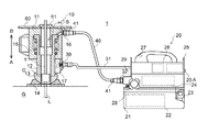
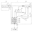
図1は、本発明の一実施形態に係る試験システムの全体構成図である。なお、図1では、ジャッキ装置10と、試験対象物の一例であるロックボルトLとが固定されている状態を示している。図2は、本発明の一実施形態に係る試験システムにおける一部の電気的な接続関係を示す図である。
FIG. 1 is an overall configuration diagram of a test system according to an embodiment of the present invention. In addition, in FIG. 1, the state which the
試験システム1は、ロックボルトLの引抜試験を行うためのシステムであり、ロックボルトLに引張力を付与するためのジャッキ装置10と、ジャッキ装置10に電力や作動油を供給する油圧ポンプ装置20と、ジャッキ装置10と油圧ポンプ装置20との間の作動油を流通させる耐圧ホース40とを有する。
The
ジャッキ装置10は、中央に貫通孔Hが形成された中空のジャッキ装置であり、シリンダチューブ11と、ピストンロッド12と、球ヘッド13と、球座14と、スプリング15と、カプラ16と、ストロークセンサ17とを備える。
The
シリンダチューブ11は、中空の円筒状部材であり、内周側壁と、外周側壁との間にピストンロッド12の一端側を所定方向に移動可能なように収容するとともに、供給される作動油を収容可能なシリンダSが形成されている。シリンダチューブ11は、1つの部材により構成されていても、複数の部材により構成されていてもよい。
The
ピストンロッド12は、一方側(図面B方向側)の端部がシリンダチューブ11により構成されたシリンダSに収容され、シリンダS内に供給される作動油に応じて、シリンダチューブ11に対してAB方向に移動可能となっている。ピストンロッド12は、スプリング15により、シリンダSにおける作動油が満たされる空間(作動油室)を狭くする方向(シリンダチューブ11に対して図面B方向)に移動するように付勢されている。したがって、ピストンロッド12は、シリンダS内に供給される作動油の圧力がスプリング15の付勢力に屈する場合、例えば、後述するレリースバルブ28が開弁されて作動油が排出されている場合には、作動油室が狭くなるように移動する。なお、ピストンロッド12は、1つの部材により構成されていても、複数の部材により構成されていてもよい。
The
球ヘッド13は、一端側(B方向側)にピストンロッド12の先端が固定され、他端側(A方向側)に球面状の面が形成されている。球座14は、ロックボルトLの取付面Gと接触する部分であり、取付面Gと反対側(B方向側)の面は、球ヘッド13の球面状の面と摺動可能な凹状の球面となっている。球ヘッド13及び球座14によると、球座14をジャッキ装置10の貫通孔Hの軸に対して所定角度の範囲内(例えば、±5度)で調整することができ、ロックボルトLの取付面Gに対する突出方向が垂直方向からずれていた場合であっても、ジャッキ装置10の貫通孔HをロックボルトLの突出方向に適切に調整でき、ロックボルトLに適切にジャッキ装置10を接続することができる。
In the spherical head 13, the tip of the
カプラ16は、シリンダSに連通する配管の先端に取り付けられ、耐圧ホース40の後述するカプラ41と着脱自在となっている。
The
ストロークセンサ17は、油圧ポンプ装置20の後述するDC−DC変換器26から供給される電力により動作し、シリンダチューブ11に対するピストンロッド12の変位量を示す変位量情報を検出し、油圧ポンプ装置20に出力する。ここで、ジャッキ装置10とロックボルトLとを接続している場合においては、ピストンロッド12の変位量が、ロックボルトL(又はロックボルトL及びテンションバーT)の変位量(延び量)に相当する。ストロークセンサ17は、例えば、ピストンロッド12が所定量移動するごとに、変位量情報として1つのパルスを出力する。ストローククセンサ17は、シリンダチューブ11のピストンロッド12の延びる側(B方向側)の面に固定されている。ストロークセンサ17の詳細については後述する。
The
ここで、ジャッキ装置10とロックボルトLとの接続について説明する。
Here, the connection between the
ロックボルトLの取付面Gからの突出長さがジャッキ装置10との接続に十分でない場合、すなわち、ジャッキ装置10の貫通孔Hに通した際に、ジャッキ装置10の他端側(B方向側)から突出する長さが十分にない場合には、ロックボルトLには、接続カプラCを介してテンションバーTが接続される。なお、突出長さが十分であれば、ロックボルトLにテンションバーTを接続しなくてもよい。
When the protruding length of the lock bolt L from the mounting surface G is not sufficient for connection with the
以下、ロックボルトLにテンションバーTが接続されている場合を例に説明する。 Hereinafter, the case where the tension bar T is connected to the lock bolt L will be described as an example.
この状態で、ロックボルトL及びテンションバーTをジャッキ装置10の貫通孔Hに挿通する。次いで、当て板60に、ジャッキ装置10のB方向に突出しているテンションバーTを通す。更に、テンションバーTの先端側に固定用のナット61を螺合させ、ジャッキ装置10が取付面Gと、当て板60との間で固定されるまでナット61を締付ける。これによって、ロックボルトLとジャッキ装置10との接続が完了する。
In this state, the lock bolt L and the tension bar T are inserted into the through hole H of the
油圧ポンプ装置20は、例えば、5kg程度の携帯可能な装置であり、本体筐体21と、作動油タンク22と、バッテリ23と、油圧ポンプ24と、USBボード25と、DC−DC変換器26と、スイッチ27と、レリースバルブ28と、圧力センサ29と、コネクタ30と、ケーブル31と、カプラ32と、を備える。ここで、本実施形態では、電力供給部は、DC−DC変換器26、コネクタ30、及びケーブル31により構成される。本実施形態では、本体筐体21内に、作動油タンク22と、油圧ポンプ24と、USBボード25と、DC−DC変換器26と、スイッチ27と、が収容されている。
The
作動油タンク22は、油圧ポンプ24により供給する作動油を貯溜する。なお、作動油タンク22には、図示しない給油口から作動油を注ぐことができるようになっている。
The
バッテリ23は、例えば、リチウムイオン電池であり、各部に電力を供給する。本実施形態では、バッテリ23は、例えば、14V〜18Vの電圧の電流を供給可能である。バッテリ23は、本体筐体21に着脱可能となっている。
The
油圧ポンプ24は、バッテリ23からの電力の供給を受けて、作動油タンク22に貯留された作動油を供給する。
The
DC−DC変換器26は、バッテリ23から供給される電圧を、各部(ストロークセンサ17、圧力センサ29、USBボード25)の動作に適した電圧に変換して各部に供給する。本実施形態では、ストロークセンサ17及び圧力センサ29に対しては、12Vの電圧の電流を供給し、USBボード25に対しては、5Vの電圧の電流を供給する。
The DC-
スイッチ27は、バッテリ23から油圧ポンプ24の図示しないモータへの電力の供給の断接を行う。
The
レリースバルブ28は、開弁することにより、油圧ポンプ24により供給されている作動油を作動油タンク22へ排出可能なバルブである。
The
圧力センサ29は、DC−DC変換器26から供給される電力により動作し、油圧ポンプ24により供給されている作動油の圧力を示す圧力値(圧力情報)を測定して、USBボード25に出力する。
The
ケーブル31は、例えば、5m程度の長さを有しており、DC−DC変換器26からストロークセンサ17に電力を供給するための配線と、ストロークセンサ17からUSBボード25に対して変位量情報を送信するための配線とを含む。
The
コネクタ30は、ケーブル31の先端に設けられ、ストロークセンサ17の後述するコネクタ57に着脱可能となっている。
The
カプラ32は、油圧ポンプ24から供給される作動油が流れる配管の先端に取り付けられ、耐圧ホース40の後述するカプラ41と着脱自在となっている。
The
USBボード25は、公知のプロセッサ、ROM、RAM、入力ポート、出力ポート等を備えている。USBボード25は、バッテリ23からDC−DC変換器26を介して供給される電力により動作する。本実施形態では、USBボード25は、USB(Universal Serial Bus)形式に従ったデータの送受信が可能な外部装置と接続可能な接続部の一例としてのUSBポート25Aを有する。USBボード25としては、例えば、テクノウェーブ株式会社製のマイコンボード(USBM3069−S)を用いることができる。
The
USBボード25は、圧力情報処理部25Bと、入力部の一例としての変位情報処理部25Cと、処理部の一例としての出力処理部25Dとを一部の機能要素として有する。
The
圧力情報処理部25Bは、圧力センサ29から圧力値を受け取り、出力処理部25Dに渡す。変位情報処理部25Cは、ケーブル31を介して、ストロークセンサ17から送信される変位量情報を受信し、ピストンロッド12の変位量を特定し、特定した変位量を出力処理部25Dに渡す。本実施形態では、変位情報処理部25Cは、ストロークセンサ17からのパルス信号中のパルスをカウントすることにより、変位量を特定する。
The pressure
出力処理部25Dは、圧力情報処理部25Bから受け取った圧力値(引張力情報の一例)と、その時点において、変位情報処理部25Cから受け取ったピストンロッド12の変位量とを対応付けて、USBポート25Aに接続された外部装置の一例であるUSB対応機器70に出力する。USB対応機器70としては、出力されたデータを記憶するUSBメモリ(USBフラッシュメモリドライブ)であってもよく、出力されたデータを受け取るPC(Personal Computer)であってもよい。例えば、USB対応機器70をPCとする場合においては、出力処理部25Dから出力される圧力値と、ピストンロッド12の変位量とから、リアルタイムにロックボルトLの変位量と荷重(引張力)とのグラフを表示させるようにしてもよい。なお、ロックボルトLに対する荷重は、使用しているジャッキ装置10における作動油の圧力値とジャッキ装置10の荷重との関係に基づいて、圧力値から特定することができる。
The
耐圧ホース40は、油圧ポンプ装置20とジャッキ装置10との間の作動油を流通させるホースであり、油圧ポンプ装置20からジャッキ装置10に供給する作動油の最大の圧力に耐え得るようになっている。耐圧ホース40の両端には、カプラ41が接続されている。カプラ41は、ジャッキ装置10のカプラ16と、油圧ポンプ装置20のカプラ32とのいずれに対しても着脱可能となっている。
The pressure-
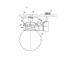
次に、ジャッキ装置10のストロークセンサ17について詳細に説明する。
Next, the
図3は、本発明の一実施形態に係るジャッキ装置のストロークセンサ周りの図である。 FIG. 3 is a view around the stroke sensor of the jack device according to the embodiment of the present invention.
ストロークセンサ17は、シリンダチューブ11のA方向側(ピストンロッド12が伸びる側)の面に固定されるベース部50と、ベース部50にスプリング52を介して接続され、ピストンロッド12側に付勢されたセンサヘッド部51と、ピストンロッド12の外周に当接され、ピストンロッド12のAB方向の移動に従動して回転するローラ53と、ローラ53が一体回転可能に接続され、センサヘッド部51に軸受55を介して回転可能に支持されたローラ軸54と、電力の供給を受けて動作することにより、ローラ軸54の回転を検出して、ピストンロッド12の所定量の移動ごとに1つのパルスを出力するセンサ回路56と、油圧ポンプ装置20のコネクタ30を接続可能なコネクタ57と、を有する。
The
次に、試験システム1による引張試験方法について説明する。
Next, a tensile test method using the
引張試験を行う準備として、まず、試験の対象とするロックボルトLに対して接続カプラCを介してテンションバーTを接続し、ロックボルトL及びテンションバーTをジャッキ装置10に固定する。すなわち、ジャッキ装置10の貫通孔Hにロックボルト及びテンションバーTを挿通し、当て板60にジャッキ装置10の貫通孔Hから飛び出ているテンションバーTを通し、テンションバーTの先端側から固定用のナット61を締め付ける。
As preparation for performing the tensile test, first, the tension bar T is connected to the lock bolt L to be tested through the connection coupler C, and the lock bolt L and the tension bar T are fixed to the
次いで、耐圧ホース40の一方のカプラ41を、ジャッキ装置10のカプラ16と接続し、耐圧ホース40の他方のカプラ41を、油圧ポンプ装置20のカプラ32と接続する。これにより、油圧ポンプ装置20からジャッキ装置10への作動油の供給経路が完成する。
Next, one
また、油圧ポンプ装置20のコネクタ30をジャッキ装置10のストロークセンサ17のコネクタ57に接続する。これにより、油圧ポンプ装置20からの電力がストロークセンサ17に供給可能となり、ストロークセンサ17からのパルス信号が油圧ポンプ装置20に出力可能となる。
Further, the
また、油圧ポンプ装置20のUSBポート25AにUSB対応装置70(ここでは、例えば、USBメモリ)を接続する。
Also, a USB compatible device 70 (here, for example, a USB memory) is connected to the USB port 25A of the
これにより、引張試験の準備が完了する。なお、引張試験の準備における各手順は、上記した順番に限られず、同一の状態にすることができるのであれば、任意の順番でよい。 This completes the preparation for the tensile test. In addition, each procedure in preparation for the tensile test is not limited to the order described above, and may be in any order as long as the same state can be obtained.
このように準備が完了すると、油圧ポンプ装置20のスイッチ27をオンにすることにより、ロックボルトLの引張試験を行うことができる。
When the preparation is completed in this way, the tensile test of the lock bolt L can be performed by turning on the
油圧ポンプ装置20のスイッチ27がオンにされて、ロックボルトLの引張試験が開始されると、油圧ポンプ装置20の油圧ポンプ24が動作し、耐圧ホース40を介して、ジャッキ装置10への作動油の供給が開始される。
When the
ジャッキ装置10への作動油の供給が開始されると、油圧ポンプ24により供給される作動油の圧力が徐々に上昇することとなる。供給されている作動油の圧力は、圧力センサ29に測定されて、圧力値がUSBボード25に出力される。これと並行して、ジャッキ装置10では、耐圧ホース40を介して作動油が供給されると、シリンダSに作動油が供給されるようになり、ピストンロッド12がシリンダチューブ11に対してA方向に移動される。
When the supply of hydraulic oil to the
この際には、ストロークセンサ17には、油圧ポンプ装置20から電力が供給されているので、ピストンロッド12がシリンダチューブ11に対してA方向に移動すると、ストロークセンサ17のローラ53がピストンロッド12に従動して回転することとなる。この結果、ストロークセンサ17は、ピストンロッド12の移動量に応じたパルスを含むパルス信号を、ケーブル31を介して油圧ポンプ装置20のUSBボード25に出力することとなる。
At this time, since electric power is supplied to the
油圧ポンプ装置20のUSBボード25では、圧力情報処理部25Bは、圧力センサ29からの圧力値を受け取り、変位情報処理部25Cは、ストロークセンサ17からのパルス信号に基づいて変位量を特定し、出力処理部25Dは、圧力情報処理部25Bから受け取った圧力値と、その時点における特定した変位量とを、USBポート25Aに接続されたUSB対応装置70に出力する。これにより、USB対応装置70では、圧力値と変位量とを関連付けて記憶したり、利用したりすることができる。
In the
以上説明したように、本実施形態に係る試験システム1によると、油圧ポンプ装置20からジャッキ装置10に供給する作動油の圧力値を測定し、また、油圧ポンプ装置20からジャッキ装置10のストロークセンサ17に電力を供給するとともに、ストロークセンサ17により検出されたピストンロッド12の変位を示すパルス信号を油圧ポンプ装置20で受信するようにし、供給する作動油の圧力値と、パルス信号に基づくピストンロッド12の変位量とを対応付けて出力するようにしたので、ロックボルトLの引張試験に必要なデータを容易且つ適切に出力することができる。また、圧力値と、変位量とを別の人が読む必要がないため、引張試験に必要な人員の数を低減することができる。
As described above, according to the
また、上記実施形態に係る試験システム1によると、ピストンロッド12の変位量を測定するストロークセンサ17を、シリンダチューブ11のピストンロッド12の延びる側に固定するようにしたので、ストロークセンサ17がシリンダチューブ11よりもB方向側に突出してしまうことがなく、外部からの接触を適切に低減することができ、ストロークセンサ17による測定又は測定精度に悪影響を与える状況を低減することができる。
Further, according to the
また、上記実施形態に係る試験システム1によると、ピストンロッド12の外周側、すなわち、ジャッキ装置10の内部側に向けたローラ53によりピストンロッド12の変位を測定するようにしたので、ストロークセンサ17がシリンダチューブ11の径方向外側に突出する量を低減することができるので、外部からの接触を適切に低減することができ、ストロークセンサ17の測定又は測定精度に悪影響を与える状況を低減することができる。
Further, according to the
なお、本発明は、上述の実施形態、実施例に限定されるものではなく、本発明の趣旨を逸脱しない範囲で、適宜変形して実施することが可能である。 The present invention is not limited to the above-described embodiments and examples, and can be appropriately modified and implemented without departing from the spirit of the present invention.
例えば、上記実施形態では、ロックボルトLを試験対象物としていたが、本発明はこれに限られず、グラウンドアンカーを試験対象物としてもよく、要は、ジャッキ装置により試験対象物に付与した引張力を特定可能な情報と、試験対象物に関する変位量とが必要となる試験の対象となる物であればよい。 For example, in the above embodiment, the lock bolt L is the test object. However, the present invention is not limited to this, and the ground anchor may be the test object. In short, the tensile force applied to the test object by the jack device. As long as it is information that can identify the object and the amount of displacement with respect to the test object, it may be an object to be tested.
また、上記実施形態では、USBボード25は、ジャッキ装置10の引張力情報として、圧力値を出力するようにしていたが、本発明はこれに限られず、ジャッキ装置10における作動油の圧力値と引張力との関係を予め把握しておき、USBボード25が、把握している関係に従って圧力値から引張力を特定し、特定した引張力を引張力情報として出力するようにしてもよい。
In the above embodiment, the
また、上記実施形態では、USBポート25Aを介して外部装置に圧力値及び変位量を出力するようにしていたが、本発明はこれに限られず、USBボード25に無線送信する機能を備え、無線通信可能な外部装置(PCやタブレット等)に無線送信するようにしてもよい。
In the above embodiment, the pressure value and the displacement amount are output to the external device via the USB port 25A. However, the present invention is not limited to this, and has a function of wirelessly transmitting to the
また、上記実施形態では、USBポート25Aを介して外部装置に出力するようにしていたが、本発明はこれに限られず、USBボード25に記憶装置を備えるようにして、その記憶装置に圧力値及び引張力情報を記憶するようにし、USBポート25Aに接続された外部装置がその記憶装置から圧力値及び引張力情報を取り出せるようにしてもよい。
Further, in the above embodiment, output is made to the external device via the USB port 25A. However, the present invention is not limited to this, and the
また、上記実施形態では、USBボード25は、バッテリ23から電力の供給を受けて動作するようにしていたが、本発明はこれに限られず、例えば、USBポート25Aを介して接続された外部装置から供給される電力(バスパワー)により動作するようにしてもよい。
In the above embodiment, the
また、上記実施形態では、USB形式のコネクタにより外部装置と接続可能にしていたが、本発明はこれに限られず、別のインターフェース形式のコネクタにより外部装置と接続するようにしてもよい。 In the above-described embodiment, the external device can be connected with the USB connector. However, the present invention is not limited to this, and the external device may be connected with another interface connector.
また、上記実施形態では、ストロークセンサとして、ローラ53を備えた接触式のストロークセンサとしていたが、本発明はこれに限られず、別形式の接触式のストロークセンサとしてもよく、非接触式のストロークセンサとしてもよい。
In the above embodiment, the contact type stroke sensor provided with the
1…試験システム、10…ジャッキ装置、11…シリンダチューブ、12…ピストンロッド、13…球ヘッド、14…球座、15…スプリング、16…カプラ、17…ストロークセンサ、20…油圧ポンプ装置、21…本体筐体、22…作動油タンク、23…バッテリ、24…油圧ポンプ、25…USBボード、25A…USBポート、26…DC−DC変換器、27…スイッチ、28…レリースバルブ、29…圧力センサ、30…コネクタ、31…ケーブル、32…カプラ、40…耐圧ホース、41…カプラ、50…ベース部、51…センサヘッド部、52…スプリング、53…ローラ、54…ローラ軸、55…軸受、56…センサ回路、57…コネクタ
DESCRIPTION OF
Claims (6)
前記ジャッキ装置は、
供給される前記作動油の圧力に応じて所定方向に移動して、前記試験対象物に引張力を付与可能なピストンロッドと、
電力の供給を受けて、前記ピストンロッドの変位量を示す変位量情報を出力するストロークセンサと、を備え、
前記油圧ポンプ装置は、
前記作動油を貯溜する作動油タンクと、
電力を供給可能なバッテリと、
前記電力により動作して前記作動油タンクの前記作動油を前記ジャッキ装置に供給可能な油圧ポンプと、
前記バッテリの電力を前記ストロークセンサに供給可能な電力供給部と、
前記ストロークセンサからの変位量情報を入力する入力部と、
前記油圧ポンプにより供給される前記作動油の圧力を示す圧力情報を検出する圧力センサと、
前記ストロークセンサからの前記変位量情報に基づく変位量と、前記圧力情報に基づく前記ジャッキ装置の前記引張力を特定可能な引張力情報とを対応付けて、記憶または外部に出力可能な処理部と、を備える
試験システム。 A test system comprising a jack device for applying a tensile force to a predetermined test object, and a hydraulic pump device for supplying hydraulic oil to the jack device,
The jack device is
A piston rod that moves in a predetermined direction according to the pressure of the supplied hydraulic oil and can apply a tensile force to the test object;
A stroke sensor that receives power supply and outputs displacement amount information indicating the displacement amount of the piston rod; and
The hydraulic pump device is
A hydraulic oil tank for storing the hydraulic oil;
A battery capable of supplying power;
A hydraulic pump operable by the electric power and capable of supplying the hydraulic oil in the hydraulic oil tank to the jack device;
An electric power supply unit capable of supplying electric power of the battery to the stroke sensor;
An input unit for inputting displacement amount information from the stroke sensor;
A pressure sensor for detecting pressure information indicating the pressure of the hydraulic oil supplied by the hydraulic pump;
A processing unit capable of storing or outputting the displacement amount based on the displacement amount information from the stroke sensor and the tensile force information capable of specifying the tensile force of the jack device based on the pressure information in association with each other. A testing system comprising:
請求項1に記載の試験システム。 2. The processing unit includes a connection unit that connects an external device to be communicable, and is capable of outputting the displacement amount and the tensile force information to the external device connected to the connection unit. Test system as described in.
請求項1に記載の試験システム。 The test system according to claim 1, wherein the processing unit can wirelessly transmit the displacement amount and the tensile force information.
前記ストロークセンサは、前記ピストンロッドの外周に接触して配置され、前記ピストンロッドの前記所定方向の移動に伴って回転するローラを備え、前記ローラの回転に応じて前記変位量情報を出力する
請求項1から請求項3の何れか一項に記載の試験システム。 The piston rod has a cylindrical shape,
The stroke sensor is disposed in contact with the outer periphery of the piston rod, and includes a roller that rotates as the piston rod moves in the predetermined direction, and outputs the displacement amount information according to the rotation of the roller. The test system according to any one of claims 1 to 3.
前記ストロークセンサは、前記シリンダチューブの前記ピストンロッドが伸縮する側の面に設けられている
請求項1から請求項4の何れか一項に記載の試験システム。 A cylinder tube for accommodating the piston rod movably in the predetermined direction;
The test system according to any one of claims 1 to 4, wherein the stroke sensor is provided on a surface of the cylinder tube on a side on which the piston rod expands and contracts.
前記作動油を貯溜する作動油タンクと、
電力を供給可能なバッテリと、
前記電力により動作して前記作動油タンクの前記作動油を前記ジャッキ装置に供給可能な油圧ポンプと、
前記バッテリの電力を外部のストロークセンサに供給可能な電力供給部と、
前記ストロークセンサからの変位量情報を入力する入力部と、
前記油圧ポンプにより供給される前記作動油の圧力を示す圧力情報を検出する圧力センサと、
前記ストロークセンサからの前記変位量情報に基づく変位量と、前記圧力情報に基づく前記ジャッキ装置の前記引張力を特定可能な引張力情報とを対応付けて、記憶可能、または外部に出力可能な処理部と、
を備える油圧ポンプ装置。 A hydraulic pump device that supplies hydraulic oil to a jack device that applies a tensile force to a predetermined test object,
A hydraulic oil tank for storing the hydraulic oil;
A battery capable of supplying power;
A hydraulic pump operable by the electric power and capable of supplying the hydraulic oil in the hydraulic oil tank to the jack device;
An electric power supply unit capable of supplying electric power of the battery to an external stroke sensor;
An input unit for inputting displacement amount information from the stroke sensor;
A pressure sensor for detecting pressure information indicating the pressure of the hydraulic oil supplied by the hydraulic pump;
Processing that can be stored in association with the displacement amount based on the displacement amount information from the stroke sensor and the tensile force information that can specify the tensile force of the jack device based on the pressure information, and can be stored externally And
A hydraulic pump device comprising:
Priority Applications (1)
| Application Number | Priority Date | Filing Date | Title |
|---|---|---|---|
| JP2016137811A JP6774239B2 (en) | 2016-07-12 | 2016-07-12 | Test system and hydraulic pump device |
Applications Claiming Priority (1)
| Application Number | Priority Date | Filing Date | Title |
|---|---|---|---|
| JP2016137811A JP6774239B2 (en) | 2016-07-12 | 2016-07-12 | Test system and hydraulic pump device |
Publications (2)
| Publication Number | Publication Date |
|---|---|
| JP2018009843A true JP2018009843A (en) | 2018-01-18 |
| JP6774239B2 JP6774239B2 (en) | 2020-10-21 |
Family
ID=60995355
Family Applications (1)
| Application Number | Title | Priority Date | Filing Date |
|---|---|---|---|
| JP2016137811A Active JP6774239B2 (en) | 2016-07-12 | 2016-07-12 | Test system and hydraulic pump device |
Country Status (1)
| Country | Link |
|---|---|
| JP (1) | JP6774239B2 (en) |
Cited By (7)
| Publication number | Priority date | Publication date | Assignee | Title |
|---|---|---|---|---|
| CN108964375A (en) * | 2018-05-30 | 2018-12-07 | 大唐东北电力试验研究院有限公司 | A kind of generator core intelligent hydraulic tension device |
| CN110057674A (en) * | 2019-05-13 | 2019-07-26 | 交通运输部公路科学研究所 | A kind of stabilized with inorganic binder material static uniaxial direct tensile modulus of resilience test method |
| CN110410384A (en) * | 2019-09-01 | 2019-11-05 | 宋彦宏 | A kind of the coming oil measurement indicator and detection method of fluid pressure line |
| JP7122064B2 (en) | 2018-06-06 | 2022-08-19 | 鹿島建設株式会社 | Pull-out test structure, ground reinforcement structure construction method, pull-out test equipment |
| CN115538501A (en) * | 2022-10-12 | 2022-12-30 | 西南交通大学 | An Anti-floating Anchor Pullout Test Device |
| CN119043927A (en) * | 2024-10-30 | 2024-11-29 | 东南大学溧阳基础设施安全与智慧技术创新中心 | Hydraulic power check out test set for mechanical test apparatus |
| CN119574318A (en) * | 2024-12-03 | 2025-03-07 | 洛阳师范学院 | Prestressed tendon shrinkage loss detection method and system based on unloading flow detection |
Citations (6)
| Publication number | Priority date | Publication date | Assignee | Title |
|---|---|---|---|---|
| US4302978A (en) * | 1971-06-16 | 1981-12-01 | Dykmans Maximiliaan J | Means and techniques useful in stressing cable |
| JPS5811831A (en) * | 1981-07-15 | 1983-01-22 | Japanese National Railways<Jnr> | Extracting and testing method for locking bolt |
| JPS6073911A (en) * | 1983-09-29 | 1985-04-26 | Meisho Kk | Tension test method and tension test device for ground anchor |
| JPH08285747A (en) * | 1995-04-17 | 1996-11-01 | Kyushu Electric Power Co Inc | Method and apparatus for shearing test in boring hole of soft rock bed |
| JP2002257654A (en) * | 2001-02-28 | 2002-09-11 | Taisei Corp | Tension measuring device |
| JP2010181387A (en) * | 2009-02-09 | 2010-08-19 | Taikoh Giken:Kk | Device for testing soil bearing with fixed beam in caisson work room, and soil bearing test method |
-
2016
- 2016-07-12 JP JP2016137811A patent/JP6774239B2/en active Active
Patent Citations (6)
| Publication number | Priority date | Publication date | Assignee | Title |
|---|---|---|---|---|
| US4302978A (en) * | 1971-06-16 | 1981-12-01 | Dykmans Maximiliaan J | Means and techniques useful in stressing cable |
| JPS5811831A (en) * | 1981-07-15 | 1983-01-22 | Japanese National Railways<Jnr> | Extracting and testing method for locking bolt |
| JPS6073911A (en) * | 1983-09-29 | 1985-04-26 | Meisho Kk | Tension test method and tension test device for ground anchor |
| JPH08285747A (en) * | 1995-04-17 | 1996-11-01 | Kyushu Electric Power Co Inc | Method and apparatus for shearing test in boring hole of soft rock bed |
| JP2002257654A (en) * | 2001-02-28 | 2002-09-11 | Taisei Corp | Tension measuring device |
| JP2010181387A (en) * | 2009-02-09 | 2010-08-19 | Taikoh Giken:Kk | Device for testing soil bearing with fixed beam in caisson work room, and soil bearing test method |
Cited By (9)
| Publication number | Priority date | Publication date | Assignee | Title |
|---|---|---|---|---|
| CN108964375A (en) * | 2018-05-30 | 2018-12-07 | 大唐东北电力试验研究院有限公司 | A kind of generator core intelligent hydraulic tension device |
| CN108964375B (en) * | 2018-05-30 | 2024-02-06 | 大唐保定热电厂 | Intelligent hydraulic tensioning device for generator iron core |
| JP7122064B2 (en) | 2018-06-06 | 2022-08-19 | 鹿島建設株式会社 | Pull-out test structure, ground reinforcement structure construction method, pull-out test equipment |
| CN110057674A (en) * | 2019-05-13 | 2019-07-26 | 交通运输部公路科学研究所 | A kind of stabilized with inorganic binder material static uniaxial direct tensile modulus of resilience test method |
| CN110410384A (en) * | 2019-09-01 | 2019-11-05 | 宋彦宏 | A kind of the coming oil measurement indicator and detection method of fluid pressure line |
| CN110410384B (en) * | 2019-09-01 | 2024-03-08 | 宋彦宏 | An oil measuring indicator and detection method for hydraulic pipelines |
| CN115538501A (en) * | 2022-10-12 | 2022-12-30 | 西南交通大学 | An Anti-floating Anchor Pullout Test Device |
| CN119043927A (en) * | 2024-10-30 | 2024-11-29 | 东南大学溧阳基础设施安全与智慧技术创新中心 | Hydraulic power check out test set for mechanical test apparatus |
| CN119574318A (en) * | 2024-12-03 | 2025-03-07 | 洛阳师范学院 | Prestressed tendon shrinkage loss detection method and system based on unloading flow detection |
Also Published As
| Publication number | Publication date |
|---|---|
| JP6774239B2 (en) | 2020-10-21 |
Similar Documents
| Publication | Publication Date | Title |
|---|---|---|
| JP2018009843A (en) | Test system and hydraulic pump device | |
| KR101692073B1 (en) | Wireless data transmitting and receiving system | |
| TWI659200B (en) | Force measurement system for sports equipment | |
| US20160161354A1 (en) | Calibration tool for torque wrench | |
| US10017234B2 (en) | System for determining a bending moment on an oar and method for determining the power on an oar | |
| US20150301088A1 (en) | Current measurement device and current measurement method | |
| JP6338760B1 (en) | Peening calibration unit, battery pack and system | |
| US8922199B2 (en) | Magnetic sensing device for fasteners | |
| CN104422372A (en) | Aperture measurement device | |
| US20170097249A1 (en) | Sensor and cable with local wireless read and write capability and methods of using same | |
| US10612992B2 (en) | Strain gauge detection and orientation system | |
| JP2014119585A (en) | Measuring apparatus | |
| JP7050039B2 (en) | Pressure gauge | |
| JP2017223499A (en) | Instrument | |
| US20170192405A1 (en) | Condition monitoring device and monitoring system using the same | |
| EP1238246B1 (en) | Apparatus and system for measuring a parameter within a closed environment | |
| CN106871958B (en) | Measuring system | |
| CN110672264A (en) | Detection system and detection method for pressure sensor of micro-electro-mechanical system | |
| US20170269130A1 (en) | Clip-On Ammeter | |
| KR102164812B1 (en) | Smart tester for electrical and electronic equipment | |
| CN214538276U (en) | Wireless passive temperature measurement sensor | |
| CN219455222U (en) | Water level gauge | |
| CN213021810U (en) | Based on two-wire system voltage formula liquid level measurement device | |
| KR200258750Y1 (en) | DC voltage is insulation resistance measuring instrument that measuring is possible | |
| RU2762155C1 (en) | Apparatus for measuring torque, configured to be connected with a fastening tool |
Legal Events
| Date | Code | Title | Description |
|---|---|---|---|
| A621 | Written request for application examination |
Free format text: JAPANESE INTERMEDIATE CODE: A621 Effective date: 20190626 |
|
| A977 | Report on retrieval |
Free format text: JAPANESE INTERMEDIATE CODE: A971007 Effective date: 20200219 |
|
| A131 | Notification of reasons for refusal |
Free format text: JAPANESE INTERMEDIATE CODE: A131 Effective date: 20200225 |
|
| A521 | Request for written amendment filed |
Free format text: JAPANESE INTERMEDIATE CODE: A523 Effective date: 20200415 |
|
| TRDD | Decision of grant or rejection written | ||
| A01 | Written decision to grant a patent or to grant a registration (utility model) |
Free format text: JAPANESE INTERMEDIATE CODE: A01 Effective date: 20200923 |
|
| A61 | First payment of annual fees (during grant procedure) |
Free format text: JAPANESE INTERMEDIATE CODE: A61 Effective date: 20201002 |
|
| R150 | Certificate of patent or registration of utility model |
Ref document number: 6774239 Country of ref document: JP Free format text: JAPANESE INTERMEDIATE CODE: R150 |
|
| R250 | Receipt of annual fees |
Free format text: JAPANESE INTERMEDIATE CODE: R250 |
|
| R250 | Receipt of annual fees |
Free format text: JAPANESE INTERMEDIATE CODE: R250 |
|
| R250 | Receipt of annual fees |
Free format text: JAPANESE INTERMEDIATE CODE: R250 |