JP2018009818A - Motor equipment - Google Patents
Motor equipment Download PDFInfo
- Publication number
- JP2018009818A JP2018009818A JP2016137123A JP2016137123A JP2018009818A JP 2018009818 A JP2018009818 A JP 2018009818A JP 2016137123 A JP2016137123 A JP 2016137123A JP 2016137123 A JP2016137123 A JP 2016137123A JP 2018009818 A JP2018009818 A JP 2018009818A
- Authority
- JP
- Japan
- Prior art keywords
- signal processing
- magnetic sensor
- processing circuit
- sensor unit
- motor
- Prior art date
- Legal status (The legal status is an assumption and is not a legal conclusion. Google has not performed a legal analysis and makes no representation as to the accuracy of the status listed.)
- Pending
Links
Images
Classifications
-
- H—ELECTRICITY
- H02—GENERATION; CONVERSION OR DISTRIBUTION OF ELECTRIC POWER
- H02K—DYNAMO-ELECTRIC MACHINES
- H02K11/00—Structural association of dynamo-electric machines with electric components or with devices for shielding, monitoring or protection
- H02K11/30—Structural association with control circuits or drive circuits
- H02K11/33—Drive circuits, e.g. power electronics
-
- G—PHYSICS
- G01—MEASURING; TESTING
- G01D—MEASURING NOT SPECIALLY ADAPTED FOR A SPECIFIC VARIABLE; ARRANGEMENTS FOR MEASURING TWO OR MORE VARIABLES NOT COVERED IN A SINGLE OTHER SUBCLASS; TARIFF METERING APPARATUS; MEASURING OR TESTING NOT OTHERWISE PROVIDED FOR
- G01D5/00—Mechanical means for transferring the output of a sensing member; Means for converting the output of a sensing member to another variable where the form or nature of the sensing member does not constrain the means for converting; Transducers not specially adapted for a specific variable
- G01D5/12—Mechanical means for transferring the output of a sensing member; Means for converting the output of a sensing member to another variable where the form or nature of the sensing member does not constrain the means for converting; Transducers not specially adapted for a specific variable using electric or magnetic means
- G01D5/14—Mechanical means for transferring the output of a sensing member; Means for converting the output of a sensing member to another variable where the form or nature of the sensing member does not constrain the means for converting; Transducers not specially adapted for a specific variable using electric or magnetic means influencing the magnitude of a current or voltage
- G01D5/142—Mechanical means for transferring the output of a sensing member; Means for converting the output of a sensing member to another variable where the form or nature of the sensing member does not constrain the means for converting; Transducers not specially adapted for a specific variable using electric or magnetic means influencing the magnitude of a current or voltage using Hall-effect devices
- G01D5/145—Mechanical means for transferring the output of a sensing member; Means for converting the output of a sensing member to another variable where the form or nature of the sensing member does not constrain the means for converting; Transducers not specially adapted for a specific variable using electric or magnetic means influencing the magnitude of a current or voltage using Hall-effect devices influenced by the relative movement between the Hall device and magnetic fields
-
- H—ELECTRICITY
- H02—GENERATION; CONVERSION OR DISTRIBUTION OF ELECTRIC POWER
- H02K—DYNAMO-ELECTRIC MACHINES
- H02K11/00—Structural association of dynamo-electric machines with electric components or with devices for shielding, monitoring or protection
- H02K11/20—Structural association of dynamo-electric machines with electric components or with devices for shielding, monitoring or protection for measuring, monitoring, testing, protecting or switching
- H02K11/21—Devices for sensing speed or position, or actuated thereby
- H02K11/215—Magnetic effect devices, e.g. Hall-effect or magneto-resistive elements
Landscapes
- Engineering & Computer Science (AREA)
- Microelectronics & Electronic Packaging (AREA)
- Power Engineering (AREA)
- Physics & Mathematics (AREA)
- General Physics & Mathematics (AREA)
- Transmission And Conversion Of Sensor Element Output (AREA)
- Measurement Of Length, Angles, Or The Like Using Electric Or Magnetic Means (AREA)
- Inverter Devices (AREA)
- Power Steering Mechanism (AREA)
Abstract
【課題】2つの信号処理回路の間のノイズの影響をより均一化したモータ装置を提供する。
【解決手段】回転角センサ60は、バイアス磁石61、磁気センサ部62、第1信号処理回路63a、および第2信号処理回路63bを有している。第1信号処理回路63aは、基板21の長手方向において、回転軸11の軸心の延長線上にある磁気センサ部62を基準として、第2信号処理回路63bと対称的に配置されている。また、インバータ40も、基板21の長手方向において、磁気センサ部62を基準として、インバータ50と対称的に配置されている。
【選択図】図3A motor device in which the influence of noise between two signal processing circuits is made more uniform is provided.
A rotation angle sensor 60 includes a bias magnet 61, a magnetic sensor unit 62, a first signal processing circuit 63a, and a second signal processing circuit 63b. The first signal processing circuit 63a is arranged symmetrically with the second signal processing circuit 63b in the longitudinal direction of the substrate 21 with reference to the magnetic sensor unit 62 on the extension line of the axis of the rotating shaft 11. The inverter 40 is also arranged symmetrically with the inverter 50 with respect to the magnetic sensor unit 62 in the longitudinal direction of the substrate 21.
[Selection] Figure 3
Description
本発明は、モータ装置に関する。 The present invention relates to a motor device.
従来、特許文献1に記載されるように、モータ装置を駆動源とする電動パワーステアリング装置が知られている。このモータ装置には、モータとモータを制御する制御装置とが一体的に設けられているものがある。
Conventionally, as described in
ところで、この制御装置には、モータの回転角を検出する回転角センサが設けられる。この回転角センサは、モータの回転軸に取り付けられた磁石の回転により生じる磁界の変化を検出する磁気センサ部と、磁気センサ部からの出力信号に基づいて回転角を演算する信号処理回路とを備えている。制御装置は、回転角センサから検出された回転角に基づいて、モータの駆動を制御する。 By the way, this control device is provided with a rotation angle sensor for detecting the rotation angle of the motor. The rotation angle sensor includes a magnetic sensor unit that detects a change in a magnetic field generated by rotation of a magnet attached to a rotation shaft of a motor, and a signal processing circuit that calculates a rotation angle based on an output signal from the magnetic sensor unit. I have. The control device controls driving of the motor based on the rotation angle detected from the rotation angle sensor.
ところで、近年、冗長化の観点から1つのモータに対して、2つの回転角センサを設ける回路構成も考えられている。これに伴って、1つのモータに対して2つの磁気センサ部と、2つの信号処理回路とが設けられる。しかし、単純に回転角センサを冗長化するだけでは、ノイズの影響が2つの信号処理回路の間で異なることにより、2つの信号処理回路から出力される出力値(回転角)の間で誤差が生じてしまう。 Incidentally, in recent years, from the viewpoint of redundancy, a circuit configuration in which two rotation angle sensors are provided for one motor has been considered. Accordingly, two magnetic sensor units and two signal processing circuits are provided for one motor. However, if the rotation angle sensor is simply made redundant, the influence of noise differs between the two signal processing circuits, so that an error occurs between the output values (rotation angles) output from the two signal processing circuits. It will occur.
本発明の目的は、2つの信号処理回路の間のノイズの影響をより均一化したモータ装置を提供することにある。 An object of the present invention is to provide a motor device in which the influence of noise between two signal processing circuits is made more uniform.
上記目的を達成しうるモータ装置は、回転軸を有するモータと、前記回転軸の回転角を検出する回転角センサと、前記モータにおける前記回転軸の一端部に設けられ、前記回転角センサを通じて検出される回転角に基づいて前記モータの駆動を制御する制御部と、を備えるモータ装置において、前記回転角センサは、前記回転軸における前記一端部に設けられる磁石と、前記磁石に対向して設けられ、前記磁石の回転に伴う磁界の変化に対応した出力信号を生成する磁気センサ部と、前記磁気センサ部に対して対称的に設けられて、前記出力信号を処理する少なくとも2つの信号処理回路と、を備えている。 A motor device that can achieve the above object is provided with a motor having a rotation shaft, a rotation angle sensor that detects a rotation angle of the rotation shaft, and one end of the rotation shaft of the motor, and is detected through the rotation angle sensor. A control unit that controls driving of the motor based on a rotation angle that is generated, wherein the rotation angle sensor is provided opposite to the magnet provided at the one end of the rotation shaft and the magnet. A magnetic sensor unit that generates an output signal corresponding to a change in a magnetic field accompanying rotation of the magnet, and at least two signal processing circuits that are provided symmetrically with respect to the magnetic sensor unit and that process the output signal And.
この構成によれば、少なくとも2つの信号処理回路が磁気センサ部に対して対称的に設けられているため、磁石から発生する磁界は、少なくとも2つの信号処理回路に対して等しくノイズとして影響する。このため、より少なくとも2つの信号処理回路の間のノイズの影響を均一化することができる。 According to this configuration, since at least two signal processing circuits are provided symmetrically with respect to the magnetic sensor unit, the magnetic field generated from the magnet affects the at least two signal processing circuits equally as noise. For this reason, the influence of noise between at least two signal processing circuits can be made more uniform.
上記のモータ装置において、前記磁気センサ部および前記少なくとも2つの信号処理回路は、同一の基板上に設けられ、前記少なくとも2つの信号処理回路は、前記回転軸の軸方向からみたとき、前記磁気センサ部に対して対称的に設けられることが好ましい。 In the above motor device, the magnetic sensor unit and the at least two signal processing circuits are provided on the same substrate, and the at least two signal processing circuits have the magnetic sensor when viewed from the axial direction of the rotating shaft. It is preferable to be provided symmetrically with respect to the part.
この構成によれば、回転軸の軸方向からみたとき、同一の基板上に対称的に少なくとも2つの信号処理部が設けられることにより、磁石から発生する磁界は、少なくとも2つの信号処理回路に等しくノイズとして影響する。 According to this configuration, when viewed from the axial direction of the rotating shaft, the magnetic field generated from the magnet is equal to at least two signal processing circuits by providing at least two signal processing units symmetrically on the same substrate. It affects as noise.
上記のモータ装置において、前記モータに電力を供給する少なくとも2つの駆動回路を含むノイズ源は、前記回転軸の軸方向からみて、前記磁気センサ部に対して対称的に設けられることが好ましい。 In the motor device described above, it is preferable that a noise source including at least two drive circuits for supplying electric power to the motor is provided symmetrically with respect to the magnetic sensor unit when viewed from the axial direction of the rotating shaft.
この構成によれば、少なくとも2つの駆動回路を含むノイズ源が磁気センサ部に対して対称的に設けられることにより、ノイズ源から少なくとも2つの信号処理回路に対して作用するノイズの影響を等しくすることができ、少なくとも2つの信号処理回路の間のノイズの影響を均一化できる。 According to this configuration, the noise source including at least two drive circuits is provided symmetrically with respect to the magnetic sensor unit, thereby equalizing the influence of noise acting on the at least two signal processing circuits from the noise source. The influence of noise between at least two signal processing circuits can be made uniform.
上記のモータ装置において、前記少なくとも2つの信号処理回路として、前記磁気センサ部に対して対称的に2つの信号処理回路が設けられており、前記回転軸の軸方向からみて、前記磁気センサ部は、前記回転軸の中心を基準として、対称的に2つ設けられており、2つの前記磁気センサ部の対称軸は、前記2つの信号処理回路の対称軸と直交していることが好ましい。 In the motor device, as the at least two signal processing circuits, two signal processing circuits are provided symmetrically with respect to the magnetic sensor unit, and when viewed from the axial direction of the rotating shaft, the magnetic sensor unit is Preferably, two symmetrically provided with respect to the center of the rotation axis, and the symmetry axes of the two magnetic sensor units are orthogonal to the symmetry axes of the two signal processing circuits.
この構成によれば、磁気センサ部の対称軸と信号処理回路の対称軸とが直交していることにより、ノイズ源の配置が多少非対称であっても、磁気センサ部あるいは信号処理回路のいずれか一方に偏ってノイズの影響が作用することが抑制される。 According to this configuration, since the symmetry axis of the magnetic sensor unit and the symmetry axis of the signal processing circuit are orthogonal to each other, either the magnetic sensor unit or the signal processing circuit can be used even if the noise source arrangement is somewhat asymmetric. The influence of noise acting on one side is suppressed.
上記のモータ装置において、前記少なくとも2つの信号処理回路として、前記磁気センサ部に対して対称的に2つの信号処理回路が設けられており、前記回転軸の軸方向からみて、前記磁気センサ部は、前記回転軸の中心を基準として、対称的に2つ設けられており、2つの前記磁気センサ部の対称軸は、前記2つの信号処理回路の対称軸と一致または平行であってもよい。 In the motor device, as the at least two signal processing circuits, two signal processing circuits are provided symmetrically with respect to the magnetic sensor unit, and when viewed from the axial direction of the rotating shaft, the magnetic sensor unit is The two symmetry axes of the two magnetic sensor units may be coincident with or parallel to the symmetry axes of the two signal processing circuits.
この構成によれば、磁気センサ部の対称軸と信号処理回路の対称軸とが直交していることにより、ノイズ源を磁気センサ部に対して対称的に設けた場合、いずれか一方の信号処理回路に偏ってノイズの影響が作用することが抑制される。 According to this configuration, when the noise source is provided symmetrically with respect to the magnetic sensor unit because the symmetry axis of the magnetic sensor unit and the symmetry axis of the signal processing circuit are orthogonal, either one of the signal processing The influence of noise on the circuit is suppressed.
本発明のモータ装置によれば、より2つの信号処理回路の間のノイズの影響を均一化できる。 According to the motor device of the present invention, the influence of noise between the two signal processing circuits can be made more uniform.
以下、モータ装置の一実施形態を説明する。本実施形態のモータ装置は、たとえば電動パワーステアリング装置の駆動源として使用される。
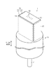
図1に示すように、モータ装置1は、モータ10、制御装置20、およびヒートシンク30を有する。モータ10は、回転軸11を有している。回転軸11の第1の端部は図1中の下方に突出している。制御装置20は、基板21,22を有している。制御装置20は、モータ10の駆動を制御する。ヒートシンク30および基板21,22は、モータ10の軸方向における端部(図1中の上端)に設けられている。ヒートシンク30は直方体状に設けられている。基板21,22は、それぞれ長方形状の板状に設けられている。基板21は、モータ10の軸方向に対して直交する向きで、ヒートシンク30におけるモータ10と反対側の端部に固定されている。また、基板22は、基板21とモータ10との間において、モータ10の軸線に沿うようにヒートシンク30の側面に設けられている。
Hereinafter, an embodiment of the motor device will be described. The motor device of this embodiment is used as a drive source of an electric power steering device, for example.
As shown in FIG. 1, the
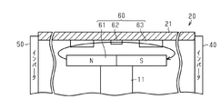
ヒートシンク30において、基板22が設けられた側面に対して直交する2つの側面には、インバータ40,50がそれぞれ設けられている。インバータ40,50は、モータ10の軸線に沿う方向において、基板21とモータ10との間に位置している。インバータ40は、ヒートシンク30を間に介して、インバータ50と対向して設けられている。なお、ヒートシンク30は、インバータ40,50の放熱を促進するために設けられている。また、モータ装置1には、インバータ40,50に近接して図示しないチョークコイルが設けられている。
In the
図2に示すように、制御装置20には、回転軸11の回転角を検出する回転角センサ60が設けられている。回転角センサ60は、円柱状のバイアス磁石61、磁気センサ部62、および信号処理回路63を有している。磁気センサ部62としては、たとえばMRセンサ(磁気抵抗効果センサ)などが採用される。バイアス磁石61は、回転軸11の第2の端部(図2中の上端)に固定されている。磁気センサ部62は、基板21に設けられている。磁気センサ部62は、回転軸11の軸線に沿う方向において、バイアス磁石61と対向している。なお、図2では、図面の簡略化のためにヒートシンク30などを省略して図示している。
As shown in FIG. 2, the
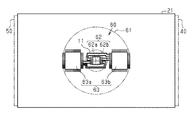
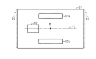
また、図3に示すように、信号処理回路63も基板21に設けられている。信号処理回路63は、磁気センサ部62と同一平面上に設けられている。信号処理回路63は、第1信号処理回路63aおよび第2信号処理回路63bを有している。第1信号処理回路63a、第2信号処理回路63b、および磁気センサ部62は、回転軸11の軸方向に対して直交する方向において、同一直線上に位置している。回転軸11の軸方向に対して直交する方向において、第1信号処理回路63aと磁気センサ部62との間の距離は、第2信号処理回路63bと磁気センサ部62との間の距離とほとんど等しい。第1信号処理回路63aは、基板21の長手方向において、磁気センサ部62を基準として、第2信号処理回路63bと対称的に配置されている。また、インバータ40も、基板21の長手方向において、磁気センサ部62を基準として、インバータ50と対称的に配置されている。このため、回転軸11の軸方向に対して直交する方向において、第1信号処理回路63aとインバータ50との間の距離は、第2信号処理回路63bとインバータ40との間の距離とほとんど同じである。また、インバータ40,50に限らず、チョークコイルを始めとする様々なノイズ源に対して第1信号処理回路63aおよび第2信号処理回路63bは、対称的あるいは等しい距離で配置されていることが好ましい。
Further, as shown in FIG. 3, the
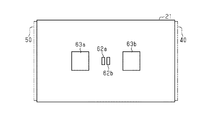
図3に示すように、回転軸11の軸方向から見て、磁気センサ部62、第1信号処理回路63a、および第2信号処理回路63bは、それぞれ四角形のICチップとして設けられている。磁気センサ部62の4つの側面には、それぞれ複数の端子が延びている。また、第1信号処理回路63aおよび第2信号処理回路63bの各側面にも、複数の端子が設けられている。磁気センサ部62は、第1磁気センサ部62aおよび第2磁気センサ部62bを有している。第1磁気センサ部62aにおける第1信号処理回路63aと対向する2つの端子が、第1信号処理回路63aにおける第1磁気センサ部62aと対向する2つの端子とそれぞれ接続されている。また、第1磁気センサ部62aにおける第2信号処理回路63bと対向する2つの端子(第1磁気センサ部62aにおける第1信号処理回路63aと反対側の端部に設けられた端子)は、第1信号処理回路63aにおける第1磁気センサ部62aと対向する2つの端子とそれぞれ接続されている。
As shown in FIG. 3, when viewed from the axial direction of the
また、第2磁気センサ部62bにおける第1信号処理回路63aと対向する2つの端子は、第2信号処理回路63bにおける第2磁気センサ部62bと対向する2つの端子と接続されている。第2磁気センサ部62bにおける第2信号処理回路63bと対向する2つの端子は、第2信号処理回路63bにおける第2磁気センサ部62bと対向する2つの端子と接続されている。第1磁気センサ部62aおよび第2磁気センサ部62bは、回転軸11の軸方向から見たとき、回転軸11の軸心に対して、対称に設けられている。また、第1磁気センサ部62aおよび第2磁気センサ部62bの対称軸は、第1信号処理回路63aおよび第2信号処理回路63bの対称軸と直交している。
In addition, the two terminals facing the first
第1磁気センサ部62aと第1信号処理回路63aとの間の接続経路、および第2磁気センサ部62bと第2信号処理回路63bとの間の接続経路を介して、第1磁気センサ部62aおよび第2磁気センサ部62bにより生成される電気信号(出力電圧)が第1信号処理回路63aおよび第2信号処理回路63bへ送られる。
The first
第1信号処理回路63aおよび第2信号処理回路63bは、取り込んだ電気信号に基づいて、回転軸11の回転角を検出する。
つぎに、磁気センサ部62の回路構成について詳しく説明する。磁気センサ部62は、バイアス磁石61から付与されるバイアス磁石の向きに応じた電気信号を生成する。
The first
Next, the circuit configuration of the
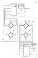
図4に示すように、第1磁気センサ部62aは、第1ブリッジ回路70および第2ブリッジ回路80を備えている。また、第1信号処理回路63aには、オペアンプ部64aおよびマイクロプロセッサ65aが設けられている。
As shown in FIG. 4, the first
第1ブリッジ回路70および第2ブリッジ回路80は、それぞれ4つのMR(磁気抵抗)素子がブリッジ状に配置されてなる。たとえば、第1ブリッジ回路では、4つのMR素子のうち2つのMR素子が直列接続されることにより第1のハーフブリッジが構成され、残る2つのMR素子が直接接続されることにより第2のハーフブリッジが構成されている。これら2つのハーフブリッジは、それぞれ電源(電源電圧「+Vcc」)とグランドとの間に並列に接続されている。第1ブリッジ回路70は、2つのハーフブリッジの中点電位を、それぞれ第1および第2の電気信号としてオペアンプ部64aへ出力する。同様に、第2ブリッジ回路80は、2つのハーフブリッジの中点電位を、それぞれ第3および第4の電気信号としてオペアンプ部64aへ出力する。回転軸11とともにバイアス磁石61が回転すると、第1磁気センサ部62aおよび第2磁気センサ部62bの各MR素子の抵抗値が変化する。各MR素子の抵抗値が変化することにより、各電気信号が変化する。すなわち、各電気信号は、回転軸11の回転角に応じて変化する。
Each of the
これら第1〜第4の電気信号は、sinまたはcosによって表すことができる。たとえば、第1の電気信号は、回転軸11の回転角に対して正弦波状に変化するsin信号であり、第2の電気信号は、第1の電気信号に対して180度だけ位相がずれた−sin信号である。また、第3の電気信号は、回転軸11の回転角に対して余弦波状に変化するcos信号であり、第4の電気信号は、第3の電気信号に対して180度だけ位相がずれた−cos信号である。
These first to fourth electric signals can be represented by sin or cos. For example, the first electric signal is a sin signal that changes in a sine wave shape with respect to the rotation angle of the
オペアンプ部64a(第1信号処理回路63a)は、第1磁気センサ部62aから受け取った第1〜第4の電気信号を所定のサンプリング周期で取り込む。オペアンプ部64aは、たとえば第1の電気信号と第2の電気信号との差分、および第3の電気信号と第4の電気信号との差分をそれぞれ出力する。
The
マイクロプロセッサ65aは、第1の電気信号と第2の電気信号との差分、および第3の電気信号と第4の電気信号との差分を取り込み、これらの差分値に基づき、逆正接値を演算することにより、回転軸11の回転角を検出する。
The
また、第2信号処理回路63bについても、第1信号処理回路63aと同様に、オペアンプ部64bおよびマイクロプロセッサ65bを有している。第2磁気センサ部62bの第3ブリッジ回路90および第4ブリッジ回路100は、第5〜第8の電気信号を出力する。オペアンプ部64bは第5〜第8の電気信号から差分値を演算し、この差分値に基づいてマイクロプロセッサ65bは回転軸11の回転角を検出する。
Similarly to the first
制御装置20は、マイクロプロセッサ65aにより演算された回転角、およびマイクロプロセッサ65bにより演算された回転角に基づいて、モータ10の駆動を制御する(図1参照)。
The
本実施形態の作用および効果について説明する。
回転角センサ60に、第1磁気センサ部62aおよび第1信号処理回路63a、ならびに第2磁気センサ部62bおよび第2信号処理回路63bが冗長的に設けられている。このため、第1磁気センサ部62aおよび第1信号処理回路63a、または第2磁気センサ部62bおよび第2信号処理回路63bに異常が発生した場合であっても、制御装置20は、モータ10の駆動の制御を継続することができる。制御装置20は、たとえば第1磁気センサ部62aで異常が発生した場合、第2磁気センサ部62bおよび第2信号処理回路63bによって検出された回転角を用いてモータ10の駆動の制御を継続すればよい。
The operation and effect of this embodiment will be described.
The
また、第1信号処理回路63aおよび第2信号処理回路63bは、磁気センサ部62を基準として、対称的に設けられている。インバータ40およびインバータ50も磁気センサ部62を基準として対称的に設けられている。このため、第1信号処理回路63aと第2信号処理回路63bとの間で、インバータ40,50のスイッチングノイズを始めとした各種のノイズによる影響に差が生じることが抑制される。第1信号処理回路63aとインバータ50との間の距離、および第2信号処理回路63bとインバータ40との間の距離がほとんど等しいため、インバータ50から第1信号処理回路63aに加わるノイズの影響は、インバータ40から第2信号処理回路63bに加わるノイズの影響とほとんど等しくなる。このため、第1信号処理回路63aと第2信号処理回路63bとの間のノイズの影響は均一化される。これにより、ノイズの影響によって、第1信号処理回路63aのマイクロプロセッサ65aにより演算される回転角と、第2信号処理回路63bのマイクロプロセッサ65bにより演算される回転角とが、ノイズの影響によって異なる値であると判定されることを抑制できる。
Further, the first
また、インバータ40,50以外の他のノイズ源についても、他のノイズ源と第1信号処理回路63aとの間の距離、および他のノイズ源と第2信号処理回路63bとの間の距離をほとんど等しくすることにより、他のノイズ源から第1信号処理回路63aおよび第2信号処理回路63bに加わるノイズの影響は均一化される。
For other noise sources other than the
また、第1信号処理回路63aおよび第2信号処理回路63bが磁気センサ部62に対して対称的に設けられることにより、バイアス磁石61の回転に伴って変化する磁気は、第1信号処理回路63aおよび第2信号処理回路63bにほとんど等しく作用する。このため、この磁気の変化がノイズとして、第1信号処理回路63aおよび第2信号処理回路63bに作用した場合であっても、第1信号処理回路63aおよび第2信号処理回路63bに加わるバイアス磁石61によるノイズの影響は均一化される。
Further, since the first
なお、各実施形態は次のように変更してもよい。以下の他の実施形態は、技術的に矛盾しない範囲において、互いに組み合わせることができる。
・本実施形態では、信号処理回路63(第1信号処理回路63aおよび第2信号処理回路63b)は、取り込んだ電気信号に基づいて回転軸11の回転角を検出したが、これに限らない。たとえば、信号処理回路63は、取り込んだ電気信号に基づいて、回転軸11の回転角のうちの基礎成分を演算してもよい。一例としては、信号処理回路63は、オペアンプ部64aのみが設けられ、信号処理回路63とは別に設けられる制御装置が、オペアンプ部64aからの出力値に基づいて、回転軸11の回転角を演算する。この場合、回転角の基礎成分は、オペアンプ部64aからの出力値である。
Each embodiment may be changed as follows. The following other embodiments can be combined with each other within a technically consistent range.
In the present embodiment, the signal processing circuit 63 (the first
・本実施形態では、基板21の長手方向において、磁気センサ部62を基準として、第1信号処理回路63aおよび第2信号処理回路63bが対称的に設けられたが、これに限らない。たとえば、基板21の短手方向において、磁気センサ部62を基準として、第1信号処理回路63aおよび第2信号処理回路63bが対称的に設けられてもよい。また、インバータ40,50を始めとするノイズ源の位置に対して、第1信号処理回路63aおよび第2信号処理回路63bが対称的に設けられるのであれば、どのように設けてもよい。たとえば、図5に示すように、磁気センサ部62を通り、かつ第1信号処理回路63aと第2信号処理回路63bとの間の中点Mを通る直線Lを基準に、第1信号処理回路63aおよび第2信号処理回路63bが対称的に設けられればよい。
In the present embodiment, the first
・本実施形態では、インバータ40,50が磁気センサ部62と対称的に設けられたが、これに限らない。たとえば、信号処理回路63がノイズ源であるインバータ40,50と十分離れている等の理由により、インバータ40,50のノイズの影響が信号処理回路63にほとんど作用しないのであれば、インバータ40,50が磁気センサ部62に対して非対称であってもよい。
In the present embodiment, the
・ノイズ源であるインバータ40,50、磁気センサ部62、および信号処理回路63は、同一基板上に実装されていてもよい。
・第1信号処理回路63aおよび第2信号処理回路63bの磁気センサ部62に対する対称性は、第1信号処理回路63aに対するノイズの影響と第2信号処理回路63bに対するノイズの影響との差がある程度(たとえば閾値よりも)小さくなる程度であればよい。
The
The symmetry of the first
・本実施形態では、磁気センサ部62は、第1磁気センサ部62aおよび第2磁気センサ部62bにより構成されたが、これに限らなくてよい。すなわち、第1信号処理回路63aおよび第2信号処理回路63bが同じ磁気センサ部に接続されてもよい。
-In this embodiment, although the
・本実施形態では、第1磁気センサ部62aおよび第2磁気センサ部62bの対称軸は、第1信号処理回路63aおよび第2信号処理回路63bの対称軸と直交していたが、これに限らない。たとえば、図6に示すように、本実施形態では、第1磁気センサ部62aおよび第2磁気センサ部62bの対称軸は、第1信号処理回路63aおよび第2信号処理回路63bの対称軸と平行であってもよい(または一致していてもよい)。
In the present embodiment, the symmetry axes of the first
・本実施形態では、基板21の短手方向において、第1磁気センサ部62aおよび第2磁気センサ部62bは対称的に設けられたが、基板21の長手方向において、第1磁気センサ部62aおよび第2磁気センサ部62bが対称的に設けられてもよいし、非対称であってもよい。
In the present embodiment, the first
・本実施形態では、信号処理回路63は第1信号処理回路63aおよび第2信号処理回路63bの2つの信号処理回路を有していたが、これに限らない。すなわち、信号処理回路63は、3つ以上の信号処理回路から構成されていてもよい。この場合、3つ以上の信号処理回路は、磁気センサ部62を基準として互いに対称的に配置されている。
In the present embodiment, the
・本実施形態では、磁気センサ部62として、たとえばMRセンサが採用されたが、これに限らない。たとえば、磁気センサ部62として、たとえばホールセンサなどの他の磁気センサが用いられてもよい。
In the present embodiment, for example, an MR sensor is used as the
1…モータ装置、10…モータ、20…制御装置、21,22…基板、30…ヒートシンク、40,50…インバータ、60…回転角センサ、61…バイアス磁石、62…磁気センサ部、62a…第1磁気センサ部、62b…第2磁気センサ部、63…信号処理回路、63a…第1信号処理回路、63b…第2信号処理回路、64a,64b…オペアンプ部、65a,65b…マイクロプロセッサ、70,80,90,100…第1〜第4ブリッジ回路。
DESCRIPTION OF
Claims (5)
前記回転角センサは、
前記回転軸における前記一端部に設けられる磁石と、
前記磁石に対向して設けられ、前記磁石の回転に伴う磁界の変化に対応した出力信号を生成する磁気センサ部と、
前記磁気センサ部に対して対称的に設けられて、前記出力信号を処理する少なくとも2つの信号処理回路と、を備えるモータ装置。 A motor having a rotation shaft, a rotation angle sensor for detecting a rotation angle of the rotation shaft, and one end portion of the rotation shaft in the motor, and based on a rotation angle detected through the rotation angle sensor; In a motor device comprising a control unit that controls driving,
The rotation angle sensor is
A magnet provided at the one end of the rotating shaft;
A magnetic sensor unit that is provided facing the magnet and generates an output signal corresponding to a change in a magnetic field accompanying rotation of the magnet;
A motor device comprising: at least two signal processing circuits which are provided symmetrically with respect to the magnetic sensor unit and process the output signal.
前記磁気センサ部および前記少なくとも2つの信号処理回路は、同一の基板上に設けられ、
前記少なくとも2つの信号処理回路は、前記回転軸の軸方向からみたとき、前記磁気センサ部に対して対称的に設けられるモータ装置。 The motor device according to claim 1,
The magnetic sensor unit and the at least two signal processing circuits are provided on the same substrate,
The motor device, wherein the at least two signal processing circuits are provided symmetrically with respect to the magnetic sensor unit when viewed from an axial direction of the rotating shaft.
前記モータに電力を供給する少なくとも2つの駆動回路を含むノイズ源は、前記回転軸の軸方向からみて、前記磁気センサ部に対して対称的に設けられるモータ装置。 The motor device according to claim 1,
A noise source including at least two drive circuits for supplying electric power to the motor is provided symmetrically with respect to the magnetic sensor unit when viewed from the axial direction of the rotating shaft.
前記少なくとも2つの信号処理回路として、前記磁気センサ部に対して対称的に2つの信号処理回路が設けられており、
前記回転軸の軸方向からみて、前記磁気センサ部は、前記回転軸の中心を基準として、対称的に2つ設けられており、
2つの前記磁気センサ部の対称軸は、前記2つの信号処理回路の対称軸と直交しているモータ装置。 The motor apparatus as described in any one of Claims 1-3 WHEREIN:
As the at least two signal processing circuits, two signal processing circuits are provided symmetrically with respect to the magnetic sensor unit,
When viewed from the axial direction of the rotating shaft, the magnetic sensor section is provided symmetrically with respect to the center of the rotating shaft,
The motor device in which the symmetry axis of the two magnetic sensor units is orthogonal to the symmetry axis of the two signal processing circuits.
前記少なくとも2つの信号処理回路として、前記磁気センサ部に対して対称的に2つの信号処理回路が設けられており、
前記回転軸の軸方向からみて、前記磁気センサ部は、前記回転軸の中心を基準として、対称的に2つ設けられており、
2つの前記磁気センサ部の対称軸は、前記2つの信号処理回路の対称軸と一致または平行であるモータ装置。 The motor apparatus as described in any one of Claims 1-3 WHEREIN:
As the at least two signal processing circuits, two signal processing circuits are provided symmetrically with respect to the magnetic sensor unit,
When viewed from the axial direction of the rotating shaft, the magnetic sensor section is provided symmetrically with respect to the center of the rotating shaft,
The motor device in which the symmetry axis of the two magnetic sensor units is coincident with or parallel to the symmetry axis of the two signal processing circuits.
Priority Applications (4)
| Application Number | Priority Date | Filing Date | Title |
|---|---|---|---|
| JP2016137123A JP2018009818A (en) | 2016-07-11 | 2016-07-11 | Motor equipment |
| US15/640,777 US10491084B2 (en) | 2016-07-11 | 2017-07-03 | Motor device |
| EP17179941.4A EP3270112B1 (en) | 2016-07-11 | 2017-07-06 | Motor device |
| CN201710556485.6A CN107612231A (en) | 2016-07-11 | 2017-07-10 | Motor apparatus |
Applications Claiming Priority (1)
| Application Number | Priority Date | Filing Date | Title |
|---|---|---|---|
| JP2016137123A JP2018009818A (en) | 2016-07-11 | 2016-07-11 | Motor equipment |
Publications (1)
| Publication Number | Publication Date |
|---|---|
| JP2018009818A true JP2018009818A (en) | 2018-01-18 |
Family
ID=59296768
Family Applications (1)
| Application Number | Title | Priority Date | Filing Date |
|---|---|---|---|
| JP2016137123A Pending JP2018009818A (en) | 2016-07-11 | 2016-07-11 | Motor equipment |
Country Status (4)
| Country | Link |
|---|---|
| US (1) | US10491084B2 (en) |
| EP (1) | EP3270112B1 (en) |
| JP (1) | JP2018009818A (en) |
| CN (1) | CN107612231A (en) |
Cited By (3)
| Publication number | Priority date | Publication date | Assignee | Title |
|---|---|---|---|---|
| WO2021199586A1 (en) * | 2020-03-31 | 2021-10-07 | 本田技研工業株式会社 | Motor structure |
| JP2022052201A (en) * | 2020-09-23 | 2022-04-04 | 多摩川精機株式会社 | Flat motor structure |
| WO2023002779A1 (en) * | 2021-07-21 | 2023-01-26 | 日立Astemo株式会社 | Power steering device |
Families Citing this family (5)
| Publication number | Priority date | Publication date | Assignee | Title |
|---|---|---|---|---|
| CN109029509A (en) * | 2018-07-13 | 2018-12-18 | 株洲时菱交通设备有限公司 | A kind of redundance type magnetic coder |
| US11573072B2 (en) * | 2018-12-13 | 2023-02-07 | Analog Devices International Unlimited Company | Magnetic position determination systems and methods |
| EP3731376A1 (en) | 2019-04-24 | 2020-10-28 | Black & Decker Inc. | Outer rotor brushless motor stator mount |
| US11231297B2 (en) | 2020-01-09 | 2022-01-25 | Robert Bosch Gmbh | Providing availability of rotary position sensor information after hardware failures |
| DE102023135412A1 (en) * | 2023-12-15 | 2025-06-18 | Rheintacho Messtechnik Gmbh | Motion sensor and corresponding method for detecting a movement |
Citations (5)
| Publication number | Priority date | Publication date | Assignee | Title |
|---|---|---|---|---|
| JPH09329460A (en) * | 1996-03-02 | 1997-12-22 | Deutsche Itt Ind Gmbh | Monolithic integrated sensor circuit |
| EP2031354A2 (en) * | 2007-08-30 | 2009-03-04 | Hitachi Ltd. | Physical quantity conversion sensor and motor control system using the same |
| US20140046625A1 (en) * | 2012-08-07 | 2014-02-13 | Micronas Gmbh | Method for determining an angle of rotation |
| US20150219472A1 (en) * | 2014-02-06 | 2015-08-06 | Infineon Technologies Ag | Axial and perpendicular angle sensor in single package |
| JP2017191093A (en) * | 2016-04-06 | 2017-10-19 | 株式会社デンソー | Rotation detection device and electric power steering device using the same |
Family Cites Families (10)
| Publication number | Priority date | Publication date | Assignee | Title |
|---|---|---|---|---|
| DK139006B (en) * | 1976-02-19 | 1978-11-27 | Ib Thomsen | Detector for sensing the angular position of a position of a compass magnet belonging to a magnetic compass. |
| EP0916074B1 (en) * | 1997-05-29 | 2003-07-30 | AMS International AG | Magnetic rotation sensor |
| DE10233080A1 (en) | 2002-07-19 | 2004-02-12 | Fernsteuergeräte Kurt Oelsch GmbH | sensor device |
| WO2008080078A2 (en) * | 2006-12-22 | 2008-07-03 | Lord Corporation | Operator interface controllable brake with field responsive material |
| WO2009033127A2 (en) * | 2007-09-07 | 2009-03-12 | Joral Devices, Llc | Rotary magnetic encoder assembly, chip and method |
| DE102009042473B4 (en) * | 2009-09-24 | 2019-01-24 | Continental Automotive Gmbh | Method for evaluating signals of an angle sensor |
| US9000763B2 (en) * | 2011-02-28 | 2015-04-07 | Infineon Technologies Ag | 3-D magnetic sensor |
| WO2013127962A1 (en) | 2012-02-29 | 2013-09-06 | Zentrum Mikroelektronik Dresden Ag | Apparatus and method for the redundant, absolute position determination of a movable body |
| JP2015206606A (en) | 2014-04-17 | 2015-11-19 | 株式会社ジェイテクト | motor |
| JP6160576B2 (en) * | 2014-07-31 | 2017-07-12 | 株式会社デンソー | DRIVE DEVICE AND ELECTRIC POWER STEERING DEVICE USING THE SAME |
-
2016
- 2016-07-11 JP JP2016137123A patent/JP2018009818A/en active Pending
-
2017
- 2017-07-03 US US15/640,777 patent/US10491084B2/en not_active Expired - Fee Related
- 2017-07-06 EP EP17179941.4A patent/EP3270112B1/en active Active
- 2017-07-10 CN CN201710556485.6A patent/CN107612231A/en active Pending
Patent Citations (6)
| Publication number | Priority date | Publication date | Assignee | Title |
|---|---|---|---|---|
| JPH09329460A (en) * | 1996-03-02 | 1997-12-22 | Deutsche Itt Ind Gmbh | Monolithic integrated sensor circuit |
| EP2031354A2 (en) * | 2007-08-30 | 2009-03-04 | Hitachi Ltd. | Physical quantity conversion sensor and motor control system using the same |
| JP2009058291A (en) * | 2007-08-30 | 2009-03-19 | Hitachi Ltd | Physical quantity conversion sensor and motor control system using the same |
| US20140046625A1 (en) * | 2012-08-07 | 2014-02-13 | Micronas Gmbh | Method for determining an angle of rotation |
| US20150219472A1 (en) * | 2014-02-06 | 2015-08-06 | Infineon Technologies Ag | Axial and perpendicular angle sensor in single package |
| JP2017191093A (en) * | 2016-04-06 | 2017-10-19 | 株式会社デンソー | Rotation detection device and electric power steering device using the same |
Cited By (4)
| Publication number | Priority date | Publication date | Assignee | Title |
|---|---|---|---|---|
| WO2021199586A1 (en) * | 2020-03-31 | 2021-10-07 | 本田技研工業株式会社 | Motor structure |
| JPWO2021199586A1 (en) * | 2020-03-31 | 2021-10-07 | ||
| JP2022052201A (en) * | 2020-09-23 | 2022-04-04 | 多摩川精機株式会社 | Flat motor structure |
| WO2023002779A1 (en) * | 2021-07-21 | 2023-01-26 | 日立Astemo株式会社 | Power steering device |
Also Published As
| Publication number | Publication date |
|---|---|
| US10491084B2 (en) | 2019-11-26 |
| EP3270112B1 (en) | 2020-01-01 |
| US20180013334A1 (en) | 2018-01-11 |
| EP3270112A1 (en) | 2018-01-17 |
| CN107612231A (en) | 2018-01-19 |
Similar Documents
| Publication | Publication Date | Title |
|---|---|---|
| JP2018009818A (en) | Motor equipment | |
| KR101737765B1 (en) | Apparatus and method for the redundant, absolute position determination of a movable body | |
| JP6455111B2 (en) | Rotation angle detector | |
| JP6033529B2 (en) | Detection device and current sensor | |
| JP3848670B1 (en) | Rotation angle detector | |
| US9851221B2 (en) | Hall sensor insensitive to external magnetic fields | |
| US20140285188A1 (en) | Detection circuit, semiconductor integrated circuit device, magnetic field rotation angle detection device, and electronic device | |
| JP2008541116A (en) | Reliable wheel rotation speed detection array device | |
| JP6319538B1 (en) | Rotation angle detector and torque sensor | |
| KR101521384B1 (en) | Mounting substrate | |
| JP2016050841A (en) | Magnetism detection device | |
| JP6473951B2 (en) | Rotation angle detector | |
| JP6455314B2 (en) | Rotation detector | |
| KR102071753B1 (en) | Magnetism-sensor device | |
| JP2021076480A (en) | Position detection device | |
| WO2014147996A1 (en) | Current sensor | |
| JP2013142604A (en) | Current sensor | |
| JP5973892B2 (en) | Magnetic detection switch and shift lever device using the magnetic detection switch | |
| JP4737372B2 (en) | Rotation angle detector | |
| JP2023088219A (en) | Angle sensor device and angle detection device | |
| JP2015090316A (en) | Current sensor | |
| WO2016190040A1 (en) | Rotation detector | |
| US20140125328A1 (en) | Magnetic detection device | |
| JP2015052556A (en) | Magnetic position detector | |
| JP2015052557A (en) | Magnetic position detector |
Legal Events
| Date | Code | Title | Description |
|---|---|---|---|
| A621 | Written request for application examination |
Free format text: JAPANESE INTERMEDIATE CODE: A621 Effective date: 20190618 |
|
| A977 | Report on retrieval |
Free format text: JAPANESE INTERMEDIATE CODE: A971007 Effective date: 20200520 |
|
| A131 | Notification of reasons for refusal |
Free format text: JAPANESE INTERMEDIATE CODE: A131 Effective date: 20200602 |
|
| A521 | Request for written amendment filed |
Free format text: JAPANESE INTERMEDIATE CODE: A523 Effective date: 20200729 |
|
| A02 | Decision of refusal |
Free format text: JAPANESE INTERMEDIATE CODE: A02 Effective date: 20200825 |