JP2017534012A - High drive ratio suspension shaft centrifugal supercharger with planetary gear mechanism - Google Patents
High drive ratio suspension shaft centrifugal supercharger with planetary gear mechanism Download PDFInfo
- Publication number
- JP2017534012A JP2017534012A JP2017512841A JP2017512841A JP2017534012A JP 2017534012 A JP2017534012 A JP 2017534012A JP 2017512841 A JP2017512841 A JP 2017512841A JP 2017512841 A JP2017512841 A JP 2017512841A JP 2017534012 A JP2017534012 A JP 2017534012A
- Authority
- JP
- Japan
- Prior art keywords
- friction wheel
- wheel
- suspension
- gear
- friction
- Prior art date
- Legal status (The legal status is an assumption and is not a legal conclusion. Google has not performed a legal analysis and makes no representation as to the accuracy of the status listed.)
- Pending
Links
Images


Classifications
-
- F—MECHANICAL ENGINEERING; LIGHTING; HEATING; WEAPONS; BLASTING
- F02—COMBUSTION ENGINES; HOT-GAS OR COMBUSTION-PRODUCT ENGINE PLANTS
- F02B—INTERNAL-COMBUSTION PISTON ENGINES; COMBUSTION ENGINES IN GENERAL
- F02B33/00—Engines characterised by provision of pumps for charging or scavenging
- F02B33/32—Engines with pumps other than of reciprocating-piston type
- F02B33/34—Engines with pumps other than of reciprocating-piston type with rotary pumps
- F02B33/40—Engines with pumps other than of reciprocating-piston type with rotary pumps of non-positive-displacement type
-
- F—MECHANICAL ENGINEERING; LIGHTING; HEATING; WEAPONS; BLASTING
- F04—POSITIVE - DISPLACEMENT MACHINES FOR LIQUIDS; PUMPS FOR LIQUIDS OR ELASTIC FLUIDS
- F04D—NON-POSITIVE-DISPLACEMENT PUMPS
- F04D29/00—Details, component parts, or accessories
- F04D29/58—Cooling; Heating; Diminishing heat transfer
- F04D29/5806—Cooling the drive system
-
- F—MECHANICAL ENGINEERING; LIGHTING; HEATING; WEAPONS; BLASTING
- F02—COMBUSTION ENGINES; HOT-GAS OR COMBUSTION-PRODUCT ENGINE PLANTS
- F02B—INTERNAL-COMBUSTION PISTON ENGINES; COMBUSTION ENGINES IN GENERAL
- F02B39/00—Component parts, details, or accessories relating to, driven charging or scavenging pumps, not provided for in groups F02B33/00 - F02B37/00
- F02B39/02—Drives of pumps; Varying pump drive gear ratio
- F02B39/04—Mechanical drives; Variable-gear-ratio drives
- F02B39/06—Mechanical drives; Variable-gear-ratio drives the engine torque being divided by a differential gear for driving a pump and the engine output shaft
-
- F—MECHANICAL ENGINEERING; LIGHTING; HEATING; WEAPONS; BLASTING
- F04—POSITIVE - DISPLACEMENT MACHINES FOR LIQUIDS; PUMPS FOR LIQUIDS OR ELASTIC FLUIDS
- F04D—NON-POSITIVE-DISPLACEMENT PUMPS
- F04D17/00—Radial-flow pumps, e.g. centrifugal pumps; Helico-centrifugal pumps
- F04D17/02—Radial-flow pumps, e.g. centrifugal pumps; Helico-centrifugal pumps having non-centrifugal stages, e.g. centripetal
- F04D17/025—Radial-flow pumps, e.g. centrifugal pumps; Helico-centrifugal pumps having non-centrifugal stages, e.g. centripetal comprising axial flow and radial flow stages
-
- F—MECHANICAL ENGINEERING; LIGHTING; HEATING; WEAPONS; BLASTING
- F04—POSITIVE - DISPLACEMENT MACHINES FOR LIQUIDS; PUMPS FOR LIQUIDS OR ELASTIC FLUIDS
- F04D—NON-POSITIVE-DISPLACEMENT PUMPS
- F04D25/00—Pumping installations or systems
- F04D25/02—Units comprising pumps and their driving means
- F04D25/028—Units comprising pumps and their driving means the driving means being a planetary gear
-
- F—MECHANICAL ENGINEERING; LIGHTING; HEATING; WEAPONS; BLASTING
- F04—POSITIVE - DISPLACEMENT MACHINES FOR LIQUIDS; PUMPS FOR LIQUIDS OR ELASTIC FLUIDS
- F04D—NON-POSITIVE-DISPLACEMENT PUMPS
- F04D29/00—Details, component parts, or accessories
- F04D29/40—Casings; Connections of working fluid
- F04D29/42—Casings; Connections of working fluid for radial or helico-centrifugal pumps
- F04D29/4206—Casings; Connections of working fluid for radial or helico-centrifugal pumps especially adapted for elastic fluid pumps
- F04D29/4226—Fan casings
-
- F—MECHANICAL ENGINEERING; LIGHTING; HEATING; WEAPONS; BLASTING
- F16—ENGINEERING ELEMENTS AND UNITS; GENERAL MEASURES FOR PRODUCING AND MAINTAINING EFFECTIVE FUNCTIONING OF MACHINES OR INSTALLATIONS; THERMAL INSULATION IN GENERAL
- F16H—GEARING
- F16H1/00—Toothed gearings for conveying rotary motion
- F16H1/28—Toothed gearings for conveying rotary motion with gears having orbital motion
- F16H1/32—Toothed gearings for conveying rotary motion with gears having orbital motion in which the central axis of the gearing lies inside the periphery of an orbital gear
-
- F—MECHANICAL ENGINEERING; LIGHTING; HEATING; WEAPONS; BLASTING
- F16—ENGINEERING ELEMENTS AND UNITS; GENERAL MEASURES FOR PRODUCING AND MAINTAINING EFFECTIVE FUNCTIONING OF MACHINES OR INSTALLATIONS; THERMAL INSULATION IN GENERAL
- F16H—GEARING
- F16H13/00—Gearing for conveying rotary motion with constant gear ratio by friction between rotary members
- F16H13/02—Gearing for conveying rotary motion with constant gear ratio by friction between rotary members without members having orbital motion
-
- F—MECHANICAL ENGINEERING; LIGHTING; HEATING; WEAPONS; BLASTING
- F16—ENGINEERING ELEMENTS AND UNITS; GENERAL MEASURES FOR PRODUCING AND MAINTAINING EFFECTIVE FUNCTIONING OF MACHINES OR INSTALLATIONS; THERMAL INSULATION IN GENERAL
- F16H—GEARING
- F16H13/00—Gearing for conveying rotary motion with constant gear ratio by friction between rotary members
- F16H13/06—Gearing for conveying rotary motion with constant gear ratio by friction between rotary members with members having orbital motion
- F16H13/08—Gearing for conveying rotary motion with constant gear ratio by friction between rotary members with members having orbital motion with balls or with rollers acting in a similar manner
-
- F—MECHANICAL ENGINEERING; LIGHTING; HEATING; WEAPONS; BLASTING
- F16—ENGINEERING ELEMENTS AND UNITS; GENERAL MEASURES FOR PRODUCING AND MAINTAINING EFFECTIVE FUNCTIONING OF MACHINES OR INSTALLATIONS; THERMAL INSULATION IN GENERAL
- F16H—GEARING
- F16H37/00—Combinations of mechanical gearings, not provided for in groups F16H1/00 - F16H35/00
- F16H37/02—Combinations of mechanical gearings, not provided for in groups F16H1/00 - F16H35/00 comprising essentially only toothed or friction gearings
-
- F—MECHANICAL ENGINEERING; LIGHTING; HEATING; WEAPONS; BLASTING
- F16—ENGINEERING ELEMENTS AND UNITS; GENERAL MEASURES FOR PRODUCING AND MAINTAINING EFFECTIVE FUNCTIONING OF MACHINES OR INSTALLATIONS; THERMAL INSULATION IN GENERAL
- F16H—GEARING
- F16H55/00—Elements with teeth or friction surfaces for conveying motion; Worms, pulleys or sheaves for gearing mechanisms
- F16H55/32—Friction members
- F16H55/34—Non-adjustable friction discs
-
- F—MECHANICAL ENGINEERING; LIGHTING; HEATING; WEAPONS; BLASTING
- F16—ENGINEERING ELEMENTS AND UNITS; GENERAL MEASURES FOR PRODUCING AND MAINTAINING EFFECTIVE FUNCTIONING OF MACHINES OR INSTALLATIONS; THERMAL INSULATION IN GENERAL
- F16H—GEARING
- F16H57/00—General details of gearing
- F16H57/08—General details of gearing of gearings with members having orbital motion
-
- F—MECHANICAL ENGINEERING; LIGHTING; HEATING; WEAPONS; BLASTING
- F16—ENGINEERING ELEMENTS AND UNITS; GENERAL MEASURES FOR PRODUCING AND MAINTAINING EFFECTIVE FUNCTIONING OF MACHINES OR INSTALLATIONS; THERMAL INSULATION IN GENERAL
- F16H—GEARING
- F16H1/00—Toothed gearings for conveying rotary motion
- F16H1/28—Toothed gearings for conveying rotary motion with gears having orbital motion
-
- F—MECHANICAL ENGINEERING; LIGHTING; HEATING; WEAPONS; BLASTING
- F16—ENGINEERING ELEMENTS AND UNITS; GENERAL MEASURES FOR PRODUCING AND MAINTAINING EFFECTIVE FUNCTIONING OF MACHINES OR INSTALLATIONS; THERMAL INSULATION IN GENERAL
- F16H—GEARING
- F16H57/00—General details of gearing
- F16H57/04—Features relating to lubrication or cooling or heating
- F16H57/0412—Cooling or heating; Control of temperature
- F16H57/0415—Air cooling or ventilation; Heat exchangers; Thermal insulations
- F16H57/0417—Heat exchangers adapted or integrated in the gearing
-
- F—MECHANICAL ENGINEERING; LIGHTING; HEATING; WEAPONS; BLASTING
- F16—ENGINEERING ELEMENTS AND UNITS; GENERAL MEASURES FOR PRODUCING AND MAINTAINING EFFECTIVE FUNCTIONING OF MACHINES OR INSTALLATIONS; THERMAL INSULATION IN GENERAL
- F16H—GEARING
- F16H57/00—General details of gearing
- F16H57/04—Features relating to lubrication or cooling or heating
- F16H57/0434—Features relating to lubrication or cooling or heating relating to lubrication supply, e.g. pumps ; Pressure control
- F16H57/0441—Arrangements of pumps
-
- F—MECHANICAL ENGINEERING; LIGHTING; HEATING; WEAPONS; BLASTING
- F16—ENGINEERING ELEMENTS AND UNITS; GENERAL MEASURES FOR PRODUCING AND MAINTAINING EFFECTIVE FUNCTIONING OF MACHINES OR INSTALLATIONS; THERMAL INSULATION IN GENERAL
- F16H—GEARING
- F16H57/00—General details of gearing
- F16H57/04—Features relating to lubrication or cooling or heating
- F16H57/0467—Elements of gearings to be lubricated, cooled or heated
- F16H57/0479—Gears or bearings on planet carriers
-
- F—MECHANICAL ENGINEERING; LIGHTING; HEATING; WEAPONS; BLASTING
- F16—ENGINEERING ELEMENTS AND UNITS; GENERAL MEASURES FOR PRODUCING AND MAINTAINING EFFECTIVE FUNCTIONING OF MACHINES OR INSTALLATIONS; THERMAL INSULATION IN GENERAL
- F16H—GEARING
- F16H57/00—General details of gearing
- F16H57/04—Features relating to lubrication or cooling or heating
- F16H57/048—Type of gearings to be lubricated, cooled or heated
- F16H57/0482—Gearings with gears having orbital motion
- F16H57/0486—Gearings with gears having orbital motion with fixed gear ratio
Abstract
【課題】【解決手段】 プーリー(11)、遊星歯車機構(12)、摩擦ホイール(13)及びサスペンション・スピンドル(14)からなるドライブユニット(1)、ファン昇圧ユニット(2)及び冷却ユニットを含み、遊星歯車機構がある高ドライブ比のサスペンションシャフトの遠心過給機。その中、遊星歯車機構(12)はギアボックス(203)にある太陽歯車(201)及び遊星歯車(202)の3つを含み、太陽歯車(201)はプーリー(11)と同軸で取り付けられ、同時に回転し、遊星歯車(202)の3つは120度で対称に太陽歯車の周りにあり、太陽歯車とエンゲージメント及びフォローを保ち、摩擦ホイール(13)は密封箱(131)にある摩擦ホイールを含み、遊星歯車(202)に対応して同軸で設置され、サスペンション・スピンドル(14)は摩擦ホイールの表面と接触摩擦を形成し、摩擦ホイールに駆動されて一同に回転し、冷却ユニットはギアボックス及び密封箱の内部にある高温潤滑油を汲み出し、冷却させてから返させる。この過給機は機械全体のドライブ精度及び増速比を向上させる同時に、耐用期間が長く、搭載しやすく、放熱性能がよく、騒音が低いという長所がある。【選択図】図1A drive unit (1) comprising a pulley (11), a planetary gear mechanism (12), a friction wheel (13) and a suspension spindle (14), a fan boosting unit (2) and a cooling unit, Centrifugal supercharger with high drive ratio suspension shaft with planetary gear mechanism. Among them, the planetary gear mechanism (12) includes three sun gears (201) and planetary gears (202) in the gear box (203), and the sun gear (201) is mounted coaxially with the pulley (11), Rotating at the same time, three of the planetary gears (202) are symmetrically around the sun gear at 120 degrees, keeping the sun gear engaged and follow, and the friction wheel (13) is the friction wheel in the sealed box (131) The suspension spindle (14) forms contact friction with the surface of the friction wheel and is driven by the friction wheel to rotate together. The cooling unit is a gearbox. And pump out the high temperature lubricating oil inside the sealed box, let it cool, and return it. This supercharger improves the drive accuracy and speed increase ratio of the entire machine, and at the same time has a long service life, is easy to install, has good heat dissipation performance, and has low noise. [Selection] Figure 1
Description
本発明は内燃発動機部品関係の技術、更に具体的に、遊星歯車機構のある高ドライブ比のサスペンションシャフトの遠心過給機に関する。 The present invention relates to a technology related to an internal combustion engine component, and more particularly to a centrifugal supercharger for a suspension shaft having a high drive ratio with a planetary gear mechanism.
内燃発動機の効率及び出力を向上するために、空気がシリンダーに入るまで過給機で圧縮されるのは普通である。それにより、同じシリンダー体積で燃料の燃焼に更に多く空気を吸い込み、出力の向上に達成できる。 In order to improve the efficiency and output of an internal combustion engine, it is common for air to be compressed with a turbocharger until it enters the cylinder. Thereby, more air is sucked into the combustion of fuel with the same cylinder volume, and an improvement in output can be achieved.
従来の発動機過給機は機械による過給及びタービンによる過給などの区分がある。その中、機械による過給は遠心型機械による過給、螺旋型過給及びルッツ型機械による過給などを含み、直接に発動機で過給機を駆動し、高密度の空気をシリンダーに送り込んで発動機の出力を向上できるので、動作が信頼でき、リニア追従性がよく、発動機の低速運転の場合に動作が優れたが、高速運転の場合に過給の効果が望ましくなく、騒音が大きすぎたものである。 Conventional motor superchargers are classified into supercharging by a machine and supercharging by a turbine. Among them, supercharging by machines includes supercharging by centrifugal machines, spiral supercharging, supercharging by Lutz machines, etc., directly driving the supercharger with a motor and feeding high-density air into the cylinder. Can improve the output of the engine, so the operation is reliable, the linear followability is good, the operation is excellent when the engine is operating at low speed, but the effect of supercharging is not desirable and the noise is high when operating at high speed It was too big.
本発明者は2010年に請求した特許CN101010593788.3で摩擦ホイール高速サスペンションシャフトの遠心過給機を提出した。その中、新規サスペンション・スピンドル及び関係の摩擦ホイールの構成の設計により回転数が向上しがたく、体積が大きく、効率が低いという従来の機械型過給機の課題を解決した同時に、構成が簡単であり、製造しやすい。しかしながら、その後の数年にわたる利用及び実測によると、その遠心過給機に下記の解決しなければいけない課題がある。 The present inventor submitted a centrifugal supercharger for friction wheel high speed suspension shaft in patent CN101010593788.3 claimed in 2010. Among them, the design of the new suspension spindle and related friction wheel configuration has solved the problems of the conventional mechanical supercharger, which is difficult to improve the rotation speed, large volume and low efficiency, and at the same time the configuration is simple It is easy to manufacture. However, according to utilization and actual measurement over the next several years, the centrifugal supercharger has the following problems that must be solved.
1)その第1段のドライブでプーリーの3つで発動機の動力を摩擦ホイールに伝えるが、荷重をかけると力を受けないプーリーがあるので、そのプーリーと摩擦ホイールとの間の荷重がゼロとなり、中心軸の滑り率の向上及び伝動効率の低下の原因となる。 1) In the first stage drive, the power of the engine is transmitted to the friction wheel with three pulleys, but when there is a load, there is a pulley that does not receive the force, so the load between the pulley and the friction wheel is zero As a result, the slip rate of the central shaft is improved and the transmission efficiency is reduced.
2)ドライブに複数のプーリーが必要であるので、発動機に搭載する場合に搭載箇所が大いに制限され、設計でも取付けでも困難である。 2) Since a plurality of pulleys are required for the drive, the mounting location is greatly limited when mounted on a motor, making it difficult to design and install.
3)主な部品として、その遠心過給機の摩擦ホイールはホイールコア、ゴムリング、鋼製ホイールセット及び磁気リングからなるが、ベンチ試験によると、回転中にゴムリングが同時に回転圧力及び円周引張力を受けるので、長期間に運転してから高周波数の耐圧力及び引張力が恢復しがたい歪みないし断裂の原因となり、中心軸及び摩擦ホイールの周期的滑りまたは過給システム全体の失効として現れる。これは回転数が向上してから特に顕著に現れる。 3) Friction wheels of the centrifugal supercharger consist of a wheel core, rubber ring, steel wheel set and magnetic ring as main parts, but according to the bench test, the rubber ring simultaneously rotates with the rotation pressure and circumference during rotation. Because it is subjected to tensile force, high frequency pressure resistance and tensile force can cause irreversible distortion or tearing after operating for a long period of time, causing periodic slip of center shaft and friction wheel or invalidation of entire supercharging system appear. This is particularly noticeable after the rotational speed is improved.
4)従来、ファンで摩擦ホイールの冷却を行う。これは過給機のドライブ効率が低中段ある場合に適切であるが、ドライブ効率が高く向上する場合、冷却の効果が有限であり、ファンの出力の向上だけで冷却の効果を保証でき、全体の荷重が向上する同時に、システムの騒音も顕著に大きくなる。 4) Conventionally, the friction wheel is cooled by a fan. This is appropriate when the drive efficiency of the turbocharger is low and middle, but if the drive efficiency is high and improved, the cooling effect is finite and the cooling effect can be guaranteed only by improving the fan output. At the same time, the system noise is significantly increased.
従来の技術の前記の欠陥または改善上の需要に鑑みて、本発明は遊星歯車機構のある高ドライブ比のサスペンションシャフトの遠心過給機を提供する。その中、その全体上の構成、ドライブの過程及びドライブユニット、摩擦ホイール及び冷却ユニットのような複数の主要部品の構成及び素の設置方式に対する改善により発動機の出力及びトルクを向上できる上、高速運転になっても顕著に全体上のドライブ精度及び増速比を向上でき、耐用期間が長く、搭載しやすく、放熱性能がよく、騒音が低いので、特に排気量の小さい様々な自家用車及びファーム車に適する。 In view of the above-mentioned deficiencies or improvements in the prior art, the present invention provides a high drive ratio suspension shaft centrifugal supercharger with a planetary gear mechanism. Among them, the output and torque of the engine can be improved by improving the overall configuration, the drive process and the configuration of multiple main parts such as the drive unit, friction wheel and cooling unit, and the installation method of the prime mover, and high speed operation However, it can significantly improve the overall drive accuracy and speed ratio, has a long service life, is easy to install, has good heat dissipation performance, and has low noise. Suitable for.
上述の目的に達成するために、本発明ではドライブユニット、ファン昇圧ユニット及び冷却ユニットを含み、遊星歯車機構及び下記の特徴がある高ドライブ比のサスペンションシャフトの遠心過給機を提供する。 In order to achieve the above-mentioned object, the present invention provides a centrifugal supercharger for a suspension shaft having a planetary gear mechanism and a high drive ratio having the following characteristics, including a drive unit, a fan boosting unit and a cooling unit.
前記のドライブユニットはプーリー、遊星歯車機構、摩擦ホイール及びサスペンション・スピンドルからなる。その中、プーリーはドライブ・ベルトにより発動機と直接に連結し、駆動され、遊星歯車機構は共にギアボックスにある太陽歯車及び遊星歯車の3つを含む。当該太陽歯車は前記のギアボックスを貫通して前記のプーリーと同軸で取り付けられ、一同に回転し、遊星歯車の3つが各々ドライブ・シャフトにより対称して前記の太陽歯車の周りに設置されていて、太陽歯車とエンゲージメント及びローを保ち、摩擦ホイールは共に密封箱にある摩擦ホイールの3組を含む。摩擦ホイールの3組は前記の遊星歯車に対応して各々同軸で前記のドライブ・シャフトにあり、一番目の同じ平面にある前摩擦ホイール及び二番目の同じ平面にある後摩擦ホイールに分けられ、サスペンション・スピンドルはその前後端でそれぞれ前記の前摩擦ホイール及び後摩擦ホイールの表面と接触摩擦を形成し、摩擦ホイールの3つ及び摩擦リングの6つの外径を支持点として共にサスペンション・スピンドルを支持し、一同に回転するようにそれを駆動する。なお、前記のギアボックスと前記の密封箱は一体に結合し、内腔が通じ合っていて潤滑油(軽質潤滑油など)が注入されている。 The drive unit includes a pulley, a planetary gear mechanism, a friction wheel, and a suspension spindle. Among them, the pulley is directly connected to and driven by a drive belt by a drive belt, and the planetary gear mechanism includes a sun gear and a planetary gear, both in a gearbox. The sun gear passes through the gear box and is mounted coaxially with the pulley, rotates together, and three of the planetary gears are respectively installed around the sun gear symmetrically by the drive shaft. Keeping the sun gear and engagement and low, the friction wheel includes three sets of friction wheels, both in a sealed box. The three sets of friction wheels are respectively coaxial and corresponding to the planetary gears on the drive shaft, divided into a front friction wheel on the first same plane and a rear friction wheel on the second same plane, The suspension spindle forms contact friction with the front and rear friction wheel surfaces at the front and rear ends of the suspension spindle, and supports the suspension spindle together with the three outer diameters of the friction wheel and the friction ring as the supporting points. And drive it to rotate all together. Note that the gear box and the sealed box are integrally coupled, the inner cavity communicates, and lubricating oil (light lubricating oil or the like) is injected.
前記のファン昇圧ユニットはキャビネット、キャビネットにある軸方向のイントレットと半径方向のアウトレット、及びキャビネットの内部にある遠心羽根車グループと軸方向の羽根車グループを含む。その中、遠心羽根車グループと軸方向の羽根車グループは相次ぎに前記のサスペンション・スピンドルの尾部に嵌められていて、それによりそのサスペンション・スピンドルに駆動されて回転し、気流が軸方向のイントレットから加速して半径方向のアウトレットへ流れるようにし、昇圧の機能を発揮する。 The fan boost unit includes a cabinet, an axial inlet and a radial outlet in the cabinet, and a centrifugal impeller group and an axial impeller group inside the cabinet. Among them, the centrifugal impeller group and the axial impeller group are successively fitted on the tail part of the suspension spindle, and are driven and rotated by the suspension spindle so that the airflow is axially introduced. Accelerates and flows to the outlet in the radial direction.
前記の冷却ユニットはギアポンプ及び油冷却器を含む。その中、ギアポンプは前記のギアボックスに内蔵し、前記の太陽歯車、遊星歯車、摩擦ホイール及びサスペンション・スピンドルの回転により温度が高くなっている潤滑油を前記の油冷却器に汲み出す。油冷却器は潤滑油を冷却して前記の密封箱に戻させるようにする。冷却潤滑油の回路に電動ポンプを搭載して油が循環して流れるようにしてもいい。 The cooling unit includes a gear pump and an oil cooler. Among them, the gear pump is incorporated in the gear box, and pumps the lubricating oil whose temperature is increased by the rotation of the sun gear, the planetary gear, the friction wheel, and the suspension spindle to the oil cooler. The oil cooler cools the lubricating oil back into the sealed box. An electric pump may be mounted on the cooling lubricating oil circuit so that the oil circulates and flows.
前記の通りに、遊星歯車機構でドライブシステムを構築するので、効果的にゼロ荷重の発生を避け、更に伝動システム全体の精度及び効率を向上でき、特に速度の1段を追加でき、即ちプーリー-太陽歯車、太陽歯車-衛星歯車及び摩擦ホイール-サスペンション・スピンドルによる三段の増速システムを形成し、顕著に従来の十分ではない増速比を改善し、運転が高速段に達しても過給効果が望ましい。それに、複数のプーリーが不要となるので、太陽歯車の歯車軸がギアボックスを貫通し、軸にドライブ・ベルトを取り付けるだけでプーリー及び発動機の動力部との連結に達成でき、搭載箇所の設計が困難である課題がなくなる同時に、摩擦ホイール回転数のずれも解決された。なお、ギアボックス及び密封箱の一括設計により、各軸、ホイール及び歯車の間の複数の接触に良好な潤滑を提供する同時に、充分に冷却効果に達成できる。実測によると、この過給機は全体的性能が従来の製品より大いに向上し、主軸の回転数最大値が72000R/分から100000R/分以上に向上し、ベンチ連続変速測定で1000時間の連続稼働時間が3000時間以上に向上し、装置全体の摩擦騒音が顕著に低下した。 As described above, since the drive system is constructed with the planetary gear mechanism, it is possible to effectively avoid the generation of zero load, and further improve the accuracy and efficiency of the entire transmission system, and in particular, one speed stage can be added, that is, pulley- Forming a three-stage speed-up system with sun gear, sun gear-satellite gear and friction wheel-suspension spindle, remarkably improving the speed ratio that is not sufficient in the past, and supercharging even when the operation reaches high speed The effect is desirable. In addition, since a plurality of pulleys are not required, the gear shaft of the sun gear penetrates the gearbox and can be connected to the pulley and the power unit of the engine simply by attaching the drive belt to the shaft, and the design of the mounting location At the same time, the problem of difficult rotation was eliminated, and at the same time, the deviation of the rotational speed of the friction wheel was solved. In addition, the collective design of the gear box and the sealed box can provide good lubrication for a plurality of contacts between the shafts, wheels, and gears, and at the same time achieve a sufficient cooling effect. According to actual measurements, the overall performance of this turbocharger is greatly improved compared to conventional products, the maximum value of the spindle speed has been increased from 72000R / min to over 100,000R / min, and 1000 hours of continuous running time is measured by continuous bench shift measurement. Improved over 3000 hours, and the friction noise of the entire device was significantly reduced.
更に、前記の各摩擦ホイールにとって、裏から表まで相次ぎにホイールコア、弾性ゴムリング及びホイールセットを含む。その中、ホイールコアはその中央で前記のドライブ・シャフトに嵌め、表の円周方向に沿って対称に表に突出する1番目の歯の複数があり、弾性ゴムリングの裏に前記の1番目の歯と協力する裏歯溝の複数があり、それによりホイールコアに付けられ、ホイールセットの裏に円周方向に沿って裏に突出する2番目の歯の複数があり、弾性ゴムリングの表にも前記の2番目の歯と協力する表歯溝の複数があり、それによりホイールセットとの取付けを行う。なお、前記の1番目の歯、2番目の歯は構成が同じであり、互いに交差して対称に分布している。 Further, each of the friction wheels includes a wheel core, an elastic rubber ring, and a wheel set successively from the back to the front. Among them, the wheel core is fitted to the drive shaft at the center, and there are a plurality of first teeth protruding symmetrically along the circumferential direction of the front, and the first of the teeth is behind the elastic rubber ring. There are a plurality of back teeth grooves that cooperate with the teeth of the wheel, thereby being attached to the wheel core, and on the back of the wheel set there are a plurality of second teeth protruding back along the circumferential direction, and the surface of the elastic rubber ring There are also a plurality of superficial grooves that cooperate with the second tooth, thereby attaching to the wheel set. The first tooth and the second tooth have the same configuration and are distributed symmetrically so as to cross each other.
摩擦ホイールの具体的な構成に関する前記の設計により、組立が完成してから、弾性ゴムリングは膨潤力があり、裏、表歯溝により更にホイールコア及びホイールセットとの精密な嵌め合い及びドライブ精度を確保する。回転の場合、1番目の歯が弾性ゴムリングを押し、ゴムリング表歯溝が続いて2番目の歯を駆動して、摩擦ホイールが連続してドライブ・シャフトに沿って安定に回転するようにし、回転の全過程にゴムリングが主に半径方向の円周の押出し圧力を受け、引張力を受けることがほとんどないので、極高速運転(90000R/分など)の場合にも中心軸及び摩擦ホイールの周期的滑りまたは過給システムの失効が発生することがない。それと同時に、構成の信頼性及び耐用期間が顕著に向上するので、頻繁に高速回転が必要である場合にとって特に重要である。 With the above design for the specific configuration of the friction wheel, after the assembly is completed, the elastic rubber ring has a swelling force, and the back and front teeth groove, and further precise fitting with the wheel core and wheel set and drive accuracy Secure. In the case of rotation, the first tooth pushes the elastic rubber ring and the rubber ring superficial groove follows to drive the second tooth so that the friction wheel continuously rotates along the drive shaft stably. The rubber ring is mainly subjected to radial circumferential extrusion pressure during the entire rotation process, and hardly receives tensile force, so the center shaft and friction wheel can be used even at extremely high speed operation (90000R / min, etc.). No periodic slipping or supercharging system expires. At the same time, the reliability and lifetime of the configuration is significantly improved, which is particularly important when frequent high speed rotation is required.
更に、前記の太陽歯車と遊星歯車との間の歯数比が1:1.5、前記の摩擦ホイールの直径とサスペンション・スピンドルとの間の直径比が1:4.456に設計され、総ドライブ比が6.68である。 Furthermore, the gear ratio between the sun gear and the planetary gear is designed to be 1: 1.5, the diameter ratio between the friction wheel and the suspension spindle is designed to be 1: 4.456, and the total drive ratio is 6.68. It is.
三段増速ドライブで設計する場合、ドライブシステムの主な仕様が最終に取得できる過給効果に同様に重要であるので、本発明では発動機応用の特徴に応じて歯車及び摩擦ホイールなどの仕様を前記のパラメータに特定するので、プーリーが1周りに回転して6.68周りに回転するようにサスペンション・スピンドルを駆動する。それと同時に、ファン羽根車グループの回転数を6.68倍に向上する。多くの対比測定によると、この増速比により高速段でも満足的な過給効果を提供できる同時に、長期間の持続的稼働の信頼性及び伝動効率も確保できる。 When designing with a three-speed drive, the main specifications of the drive system are equally important for the supercharging effect that can be finally obtained, so in the present invention, the specifications of gears and friction wheels, etc. according to the characteristics of the motor application , The suspension spindle is driven so that the pulley rotates around 1 and rotates around 6.68. At the same time, the fan impeller group speed is increased by 6.68 times. According to many contrast measurements, this speed increase ratio can provide a satisfactory supercharging effect even at a high speed stage, and at the same time can ensure the reliability and transmission efficiency of long-term continuous operation.
更に、前記のギアポンプはオイルポンプに交換してギアボックスの外部に搭載できる。 Furthermore, the gear pump can be replaced with an oil pump and mounted outside the gear box.
更に、前記のホイールコアがアルミ合金製ホイールコア、前記の弾性ゴムリングの素材が水素化ニトリルゴムのような温度幅の広い素材、前記のホイールセットが軸受鋼製である。 Furthermore, the wheel core is made of an aluminum alloy, the elastic rubber ring is made of a material having a wide temperature range such as hydrogenated nitrile rubber, and the wheel set is made of bearing steel.
全体として、従来の技術より、本発明による前記の技術案は技術上の長所が主に次の通りである。 Overall, the technical advantages of the present invention according to the present invention are mainly as follows from the prior art.
1.ドライブシステムの部品、構成及び設置方式に関する設計により三段の効率向上の激励を取得し、従来の過給機のゼロ荷重の現象を克服し、効果的に利得比及び伝動効率のボトルネック課題できる。測定によると、その最高回転数が100000R/分以上に達成できる。それと同時に、発動機に搭載にすること関する設計に便利であり、特に高速段の過給効果を顕著に改善した。 1. The drive system components, configuration and installation system design encourages three-stage efficiency improvement, overcomes the zero-load phenomenon of conventional turbochargers, and can effectively bottleneck the gain ratio and transmission efficiency . According to the measurement, the maximum rotation speed can be achieved over 100,000R / min. At the same time, it is convenient for the design related to mounting on the motor, and especially the supercharging effect of the high speed stage is remarkably improved.
2.摩擦ホイールの具体的な構成に対する改善により、コストの高い磁気リング部品が不要となり、製造が容易になった。なお、長い耐用期間にあっても、摩擦ホイールも支持及びドライブで良好に役に立ち、周期的滑り及び断裂のおそれがないので、ドライブシステムの回転精度が向上する同時に、信頼性及び耐用期間の向上にも役に立つ。 2. Improvements to the specific configuration of the friction wheel eliminates the need for costly magnetic ring components and facilitates manufacture. Even during a long service life, the friction wheel is also useful for support and drive, and there is no risk of periodic slipping and tearing, which improves the rotational accuracy of the drive system and at the same time improves reliability and service life. Also useful.
3.測定によると、ギアボックス、密封箱及び冷却システムに対する設計により、良好な潤滑を提供する同時に、充分に冷却効果を取得でき、ベンチ連続変速の測定結果によると、連続的稼働時間が従来の製品の1000時間から3000時間以上に向上できる。この一括設計ではコンパクト、適切な取付けフレームも提供し、装置全体の摩擦騒音が顕著に低下した。 3. Measurements show that the gearbox, sealed box and cooling system design provide good lubrication while at the same time providing sufficient cooling effect, and the continuous bench shift measurement results show that the continuous running time It can be improved from 1000 hours to over 3000 hours. This collective design also provided a compact and appropriate mounting frame, which significantly reduced the friction noise of the entire device.
4.本発明によるサスペンションシャフトの遠心過給機は全体の構成がコンパクトであり、立ち上げ及び取付けに便利であり、ドライブ比が高く、長期間に使用しても安全であり、信頼でき、装置全体の騒音が低く、高速段にあっても満足的な過給効果を提供できるので、特に排気量1.0L〜2.0L(例えば1.2L或は1.6L)の小排気量の車、及び高原、山地などのための各種の自家用車またはファーム車に適する。 4). The centrifugal supercharger of the suspension shaft according to the present invention has a compact overall configuration, is convenient for start-up and installation, has a high drive ratio, is safe even when used for a long period of time, and is reliable. Low noise and can provide a satisfactory supercharging effect even at high speeds, especially cars with small displacements of 1.0L to 2.0L (eg 1.2L or 1.6L), highlands, mountains, etc. Suitable for various kinds of private cars or farm cars.
次に、図及び実例と結び合わせて本発明について詳しく説明する。ちなみに、ここの実例が本発明について説明するためのものだけであり、本発明を限定するものではない。なお、本発明に関する下記の各実施方式に関する技術上の特徴は対立しない限り相互に組み合うことができる。 Next, the present invention will be described in detail in conjunction with the drawings and examples. By the way, the examples here are only for explaining the present invention and are not intended to limit the present invention. It should be noted that the technical features related to the following respective implementation modes relating to the present invention can be combined with each other as long as there is no conflict.
図1は本発明による遠心過給機の全体の構成及レイアウト図である。図1の通りに、当該遠心過給機は主にドライブユニット1、ファン昇圧ユニット2及び冷却ユニット3などの機能ユニットを含む。その中、従来の機械型過給機の各種課題について、同時に、本発明者のこの前の製品の応用実践及びベンチの測定結果(詳細は「背景技術」を参照すること)を参照して当該機能部品の構成及びその設置方式を検討し、装置全体の増速比の向上、高速段の過給効果の確保、騒音降下、全体的性能の改善及び長期使用の場合の信頼性などの目的に達成するようにする。 FIG. 1 is an overall configuration and layout diagram of a centrifugal supercharger according to the present invention. As shown in FIG. 1, the centrifugal supercharger mainly includes functional units such as a drive unit 1, a fan boosting unit 2, and a cooling unit 3. Among them, regarding various problems of the conventional mechanical supercharger, at the same time, refer to the application practice of the previous product of the present inventor and the measurement result of the bench (for details, refer to “Background Art”). Examine the composition of functional parts and their installation methods, and improve the overall gear ratio, ensure high-speed supercharging effect, reduce noise, improve overall performance, and improve reliability in long-term use. To achieve.
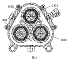
具体的に、図1及び2の通りに、前記のドライブユニット1はプーリー11、遊星歯車機構12、摩擦ホイール組13及びサスペンション・スピンドル14からなる。例として、プーリー11はドライブ・ベルトにより発動機の動力部と直接に連結して駆動の動力を取得する。本発明による重要な改善の一つとして、遊星歯車機構12は共にギアボックス203にある太陽歯車201及び遊星歯車202の3つを含む。当該太陽歯車201は直径が長く、一同に回転するように、その一端(図1の中の左端)が直接にギアボックス203を貫通し、プーリー11と同軸でドライブ・シャフト取り付けられ、遊星歯車202の3つは構成が同じであり、直径が短く、それぞれ自体のドライブ・シャフト204及びその関係の遊星キャリアにより対称に太陽歯車201の周りに設置され、太陽歯車201とエンゲージメントを保つ。それにより、大歯車が回転する場合にそれとエンゲージメントする小歯車の3つを駆動して同期に回転する。例として、摩擦ホイール組13は3組を含み、各組の数量を摩擦ホイールの2つにしてそれぞれ前後に設置してもいい(もちろん、各組に更に多くの摩擦ホイールを含んでもいい。本発明でドライブ効率と構成のコンパクトさとの間のバランスを考えて前後配置の二重摩擦ホイールの形式にした。なお、優先して各摩擦ホイールをサスペンションシャフの半径方向の120度で配置する)。摩擦ホイール組13のすべての摩擦ホイール132が密封箱131、即ち摩擦ホイール箱の内部にあり、且つ各組の摩擦ホイールがそれぞれ遊星歯車の1つに対応し、同軸を保ってドライブ・シャフト204にあるので、遊星歯車同期に回転する場合に同一の軸に固定された摩擦ホイールの一組を駆動して回転させる。なお、図4の通りに、この摩擦ホイールの三組で、ドライブ・シャフトの前端にある摩擦ホイールが共に同一の平面にあるので、回転する場合に運動軌跡も同一の平面にあり、前摩擦ホイールの3つの中心点の連結線が優先して正三角形を形成し、ホイールの3つの縁部が支持点の3つとして共にサスペンション・スピンドルの前端を支持し、摩擦接触によりそれを駆動して回転させる。前記の摩擦ホイールの三組で、ドライブ・シャフトの後端にある摩擦ホイールが同様に他の同一の平面で保ち、前記と同じ方式でサスペンション・スピンドルの後端を支持し、前摩擦ホイールと共同して働いてドライブの過程を実行する。サスペンション・スピンドル14はその前後端でそれぞれ前摩擦ホイールの3つ及び後摩擦ホイールの3つの表面と接触摩擦を形成するので、軸受がなくても同期の高速回転を実行できる。
Specifically, as shown in FIGS. 1 and 2, the drive unit 1 includes a
それにより、ドライブシステムにプーリーの3つが不要となるので、効果的にプーリーと摩擦ホイールとの間の高すぎたゼロ荷重及び滑り率の課題を解決できる上、発動機への搭載にも非常に便利であり。これは従来の各種の車における装置改造及び製品適用性の拡大に対しても非常に重要である。特に、ギアボックスに増速の1段を添加したので、全体的増速比が顕著に向上した。太陽歯車と遊星歯車の歯数比が1:1.5、摩擦ホイールとサスペンション・スピンドルとの直径比が1:4.456という優先のドライブパラメータを例にすると、過給機の回転数比が6.68倍、発動機の主軸プーリーから過給機プーリーまでの増速比が1:2.5となるので、総ドライブ比が16.7倍となり、プーリーがホイールの1つを駆動すると、6.68周りに回転するようにサスペンション・スピンドルを駆動でき、サスペンション・スピンドルにあるファン羽根車グループ回転数同時に16.7倍に向上しているので、ファン昇圧ユニットからの気流の増速が更に速くなり、圧力が向上し、気流が大きくなるので、稼働効率及び過給効果が大いに改善される。 This eliminates the need for three pulleys in the drive system, effectively solving the problem of excessively high zero load and slippage between the pulley and the friction wheel, as well as being mounted on the motor. It is convenient. This is also very important for retrofitting equipment and increasing product applicability in various conventional vehicles. In particular, the addition of one speed increase to the gearbox significantly improved the overall speed increase ratio. Taking the priority drive parameters of the sun gear and planetary gear ratio of 1: 1.5 and the friction wheel to suspension spindle diameter ratio of 1: 4.456 as an example, the turbocharger speed ratio is 6.68 times Since the speed ratio from the main spindle pulley to the turbocharger pulley is 1: 2.5, the total drive ratio is 16.7 times, and when the pulley drives one of the wheels, the suspension spindle rotates around 6.68 Since the fan impeller group speed on the suspension spindle is simultaneously improved by 16.7 times, the speed of the air flow from the fan boost unit is further increased, the pressure is improved, and the air flow is increased. The operating efficiency and supercharging effect are greatly improved.
ファン昇圧ユニット2はキャビネット21、キャビネット21にある軸方向のイントレット22と半径方向のアウトレット23、及びキャビネット21の内部にある遠心羽根車グループ24と軸方向の羽根車グループ25を含むことができる上、軸方向の空気通路、羽根車室及び棚なども設置できる。その中、遠心羽根車グループ24と軸方向の羽根車グループ25は相次ぎにサスペンション・スピンドル14の尾部(図1で右端に表示される)に嵌められていて、それによりそのサスペンション・スピンドルに駆動されて同期回転を行い、気流が軸方向のイントレット22から加速して半径方向のアウトレット23に流れるようにして過給機能を発揮する。
The fan boosting unit 2 can include a
本発明による重要な改善のもう一つとして、ギアボックス203と密封箱131がつながっていて一括設計され、二者の内腔が通じ合っていて潤滑油が注入されている。その協力措置として、本発明では冷却及び降温のための冷却ユニットも設置する。当該冷却ユニットはギアポンプ及び油冷却器などを含む。その中、ギアポンプは直接にギアボックスに内蔵された一部の歯車ユニットを利用でき、太陽歯車201、遊星歯車202、摩擦ホイール132及びサスペンション・スピンドル14の間の高速回転により温度が向上した潤滑オイルを汲み出し、油冷却器に送って降温処理を行い、密封箱131に返す。なお、ギアポンプで外部の電動オイルポンプを代替して更に機器の体積を小さくし、構成のコンパクトさを向上してもいい。
As another important improvement according to the present invention, the
前記の通りに設計を行ったのは、ドライブユニットでの摩擦力が直接に装置全体の負荷力及びドライブ効率に影響を及ぼすことを考えたからである。従来の通りに潤滑脂またはファンで冷却を行う場合、中低回転数の場合に適用するが、ドライブ効率が所定の程度に達してから、冷却効果が非常に有限的になり、ファン出力の向上がシステム騒音の迅速的な悪化につながる。よって、本発明で摩擦ホイール箱を密封体にし、ギアボックスと一体化の組合せ設計を行い、通じている腔に潤滑油を注入する。それにより複数の歯車、摩擦ホイール、ドライブ・シャフト、軸受及びサスペンション・スピンドルなどに充分に潤滑を提供できる上、騒音の向上がないで良好な冷却効果を提供することも確保できる。前記の全体上の構成設計により、本発明による遠心過給機は主軸の回転数の最大値が72000R/分から100000R/分以上に向上できる。なお、ベンチ連続変速の測定結果によると、連続的稼働時間が従来の製品の1000時間から3000時間以上に向上できるので、実際な応用上の価値が更に高い。 The reason for designing as described above is that the friction force in the drive unit directly affects the load force and drive efficiency of the entire apparatus. When cooling with grease or a fan as before, it is applied to medium and low rotation speeds, but after the drive efficiency reaches a predetermined level, the cooling effect becomes very finite and the fan output is improved. Will lead to rapid deterioration of system noise. Therefore, according to the present invention, the friction wheel box is used as a sealed body, and the combination design is integrated with the gear box, and the lubricating oil is injected into the communicating cavity. As a result, sufficient lubrication can be provided to a plurality of gears, friction wheels, drive shafts, bearings, suspension spindles, and the like, and a good cooling effect can be ensured without increasing noise. With the above overall structural design, the centrifugal turbocharger according to the present invention can improve the maximum value of the rotational speed of the main shaft from 72000 R / min to 100000 R / min or more. In addition, according to the measurement result of the bench continuous shift, the continuous operation time can be improved from 1000 hours to 3000 hours or more of the conventional product, so the practical application value is even higher.
図3は本発明による新型摩擦ホイールの構成の断面図である。本発明のもう一つの重要な性改善として、この摩擦ホイールは最大回転数の向上及び回転精度と長期間運転の信頼性の確保などに対して同様に重要な働きを発揮している。 FIG. 3 is a cross-sectional view of the configuration of a new friction wheel according to the present invention. As another important improvement in the present invention, the friction wheel also plays an important role in improving the maximum rotational speed and ensuring the rotational accuracy and reliability of long-term operation.
具体的に、例として、各摩擦ホイール132裏から表まで相次ぎにアルミホイールのためのホイールコア1321、弾性ゴムリング1322及びホイールセット1323を含む。その中、ホイールコアはその中央で各ドライブ・シャフト204に嵌められて遊星歯車と同軸を保ち、表の円周方向に沿って対称に表に突出する1番目の歯の複数があり、弾性ゴムリング1322の裏に1番目の歯と協力する裏歯溝の複数があり、それによりしっかり吻合してホイールコアに付けられ、ホイールセット1323の裏に円周方向に沿って裏に突出する2番目の歯の複数があり、弾性ゴムリング1322の外表面に同様に2番目の歯と協力する表歯溝の複数があり、それによりホイールセットとの取付けを行う。なお、前記の1番目の歯、2番目の歯は構成が同じであり、互いに交差して対称に分布している。
Specifically, as an example, each
摩擦ホイールの構成に関する前記の設計により、組立が完成してから、ゴムリングに膨潤力があり、且つ1番目の歯及び2番目の歯とずらして嵌め合う裏表の歯溝があるので、ホイールコア及びホイールセットとの精密な嵌め合い及びドライブ精度が更に確保される。アルミホイールが回転する場合、アルミホイール歯がゴム部品押し、ゴム部品の歯溝が摩擦リング歯、摩擦リングが中心軸を駆動して回転させる。この場合、ゴム部品は主に半径方向の円周の押出し圧力を受け、引張力がほとんどない。よって、ゴム部品は耐用期間が長くなる。更に重要なのは、摩擦ホイールの回転数のピークが更に向上し、極高速運転の場合にも中心軸及び摩擦ホイールの周期的滑りまたは過給システムの失効のおそれがない。 With the above design for the configuration of the friction wheel, since the rubber ring has swelling power after assembly is completed and there is a back and front tooth gap that fits with the first and second teeth, the wheel core In addition, precise fitting with the wheel set and drive accuracy are further ensured. When the aluminum wheel rotates, the aluminum wheel teeth push the rubber part, the tooth groove of the rubber part drives the friction ring teeth, and the friction ring drives the central axis to rotate. In this case, the rubber component is mainly subjected to a radial circumferential extrusion pressure and has almost no tensile force. Therefore, the rubber component has a long service life. More importantly, the peak speed of the friction wheel is further improved, and there is no risk of periodic slippage of the central shaft and friction wheel or deactivation of the supercharging system even at very high speed operation.
まとめて言うと、本発明による遊星歯車機構のあるサスペンションシャフトの遠心過給機は発動機の出力及びトルクを向上する同時に、運転が高速段に達してからも顕著に装置全体のドライブ精度及び増速比を向上でき、耐用期間が長く、搭載しやすく、放熱性能がよく、騒音が低いので、特に各種のクランクシャフトシステムの発動機への搭載、及び排気量が例として1.4L、1.6Lである自家用車及びファーム車などに適し、出力の向上、トルクの増大及び排出の削減などで役に立つ。 In summary, the centrifugal turbocharger of the suspension shaft with the planetary gear mechanism according to the present invention improves the output and torque of the motor, and at the same time, significantly improves the drive accuracy and increase of the entire device even after the operation reaches a high speed stage. The speed ratio can be improved, the service life is long, it is easy to install, the heat dissipation performance is good, and the noise is low. Especially, it is mounted on the engine of various crankshaft systems and the displacement is 1.4L, 1.6L as an example It is suitable for some private cars and farm cars, and is useful for improving output, increasing torque and reducing emissions.
前記が本発明の実例だけであり、本発明を制限するものではなく、本発明の精神及び原則の範囲にあるいかなる改訂、同等の交換または改善などの全部が本発明の範囲に属する。 The foregoing is only illustrative of the present invention and is not intended to limit the present invention, and all revisions, equivalent replacements or improvements within the spirit and principle of the present invention are within the scope of the present invention.
1…ドライブユニット 2…ファン昇圧ユニット 11…プーリー 12…遊星歯車機構 13…摩擦ホイール組 14…サスペンション・スピンドル 21…キャビネット 22…軸方向のイントレット 23…半径方向のアウトレット 24…遠心羽根車グループ 25…軸方向の羽根車グループ 201…太陽歯車 202…遊星歯車 203…ギアボックス 204…ドライブ・シャフト 131…密封箱 132…摩擦ホイール 1321…ホイールコア 1322…弾性ゴムリング 1323…ホイールセット
1 ... Drive unit 2 ...
Claims (5)
前記のドライブユニット(1)はプーリー(11)、遊星歯車機構(12)、摩擦ホイール(13)及びサスペンション・スピンドル(14)からなる。その中、プーリー(11)はドライブ・ベルトにより発動機と直接に連結し、駆動され、遊星歯車機構(2)共にギアボックス(203)にある太陽歯車(201)及び遊星歯車(202)の3つを含み、当該太陽歯車(201)は前記のギアボックス(203)を貫通して前記のプーリー(11)と同軸で取り付けられ、一同に回転し、遊星歯車(202)の3つが各々ドライブ・シャフト(204)により120度で対称して前記の太陽歯車(201)の周りにあり、太陽歯車とエンゲージメント及びローを保ち、摩擦ホイール(13)は共に密封箱(131)にある摩擦ホイールの3組を含む。摩擦ホイールの3組は前記の遊星歯車(202)に対応して各々同軸で前記のドライブ・シャフト(204)にあり、一番目の同じ平面にある前摩擦ホイール及び二番目の同じ平面にある後摩擦ホイールに分けられ、サスペンション・スピンドル(14)はその前後端でそれぞれ前記の前摩擦ホイール及び後摩擦ホイールの表面と接触摩擦を形成し、摩擦ホイールの3つは120°で摩擦リングの6つの外径を支持点として共にサスペンション・スピンドルを支持し、一同に回転するようにそれを駆動する。なお、前記のギアボックス(203)と前記の密封箱(131)は一体に結合し、内腔が通じ合っていて潤滑油が注入されている。
前記のファン昇圧ユニット(2)はキャビネット(21)、キャビネット(21)にある軸方向のイントレット(22)と半径方向のアウトレット(23)、及びキャビネット(21)の内部にある遠心羽根車グループ(24)と軸方向の羽根車グループ(25)を含む。その中、遠心羽根車グループ(25)と軸方向の羽根車グループ(24)は相次ぎに前記のサスペンション・スピンドル(14)の尾部に嵌められていて、それによりそのサスペンション・スピンドルに駆動されて回転し、気流が軸方向のイントレット(22)から加速して半径方向のアウトレット(23)へ流れるようにし、昇圧の機能を発揮する。
前記の冷却ユニットはギアポンプ及び油冷却器を含む。その中、ギアポンプは前記のギアボックスに内蔵し、前記の太陽歯車、遊星歯車、摩擦ホイール及びサスペンション・スピンドルの回転により温度が高くなっている潤滑油を前記の油冷却器に汲み出す。油冷却器は潤滑油を冷却して前記の密封箱(131)に戻させるようにする。 A centrifugal supercharger for a suspension shaft with a high drive ratio including a drive unit, a fan boost unit and a cooling unit, and a planetary gear mechanism and the following characteristics.
The drive unit (1) includes a pulley (11), a planetary gear mechanism (12), a friction wheel (13), and a suspension spindle (14). Among them, the pulley (11) is directly connected to the motor by the drive belt and is driven, and the planetary gear mechanism (2) is the sun gear (201) and planetary gear (202) 3 in the gearbox (203). The sun gear (201) passes through the gear box (203), is coaxially mounted with the pulley (11), rotates together, and the three planetary gears (202) 3 of the friction wheel located around the sun gear (201) symmetrically at 120 degrees by the shaft (204), keeping the sun gear and engagement and low, and the friction wheel (13) together in the sealed box (131). Includes pairs. Three sets of friction wheels are co-axial with the drive shaft (204), corresponding to the planetary gear (202), respectively, the first friction wheel in the same plane and the second in the same plane The suspension spindle (14) forms contact friction with the front and rear friction wheel surfaces at the front and rear ends, respectively, and three of the friction wheels are 120 ° and six of the friction rings The suspension spindle is supported together with the outer diameter as a supporting point, and it is driven to rotate together. Note that the gear box (203) and the sealed box (131) are integrally coupled, and the inner cavity communicates with the lubricating oil.
The fan boosting unit (2) includes a cabinet (21), an axial inlet (22) and a radial outlet (23) in the cabinet (21), and a centrifugal impeller group in the cabinet (21). (24) and axial impeller group (25) included. Among them, the centrifugal impeller group (25) and the axial impeller group (24) are successively fitted on the tails of the suspension spindle (14), thereby being driven and rotated by the suspension spindle. The air flow is accelerated from the axial inlet (22) and flows to the radial outlet (23), thereby exerting a boosting function.
The cooling unit includes a gear pump and an oil cooler. Among them, the gear pump is incorporated in the gear box, and pumps the lubricating oil whose temperature is increased by the rotation of the sun gear, the planetary gear, the friction wheel, and the suspension spindle to the oil cooler. The oil cooler cools the lubricating oil back to the sealed box (131).
前記の各摩擦ホイール(132)にとって、裏から表まで相次ぎにホイールコア(1321)、弾性ゴムリング(1322)及びホイールセット(1323)を含むことを特徴とする請求項1に記載のサスペンションシャフトの遠心過給機。 The wheel core (1321) is fitted to the drive shaft (204) at the center, and there are a plurality of first teeth that protrude symmetrically along the circumferential direction of the table, and the elastic rubber ring (1322) The back has a plurality of back tooth grooves cooperating with the first tooth, so that it is attached to the wheel core (1321) and protrudes back along the circumferential direction on the back of the wheel set (1323) The elastic rubber ring (1322) also has a front tooth groove cooperating with the second tooth, thereby mounting with the wheel set (1323). The first tooth and the second tooth have the same configuration and are distributed symmetrically across each other.
The suspension shaft according to claim 1, wherein each friction wheel (132) includes a wheel core (1321), an elastic rubber ring (1322), and a wheel set (1323) successively from the back to the front. Centrifugal supercharger.
Applications Claiming Priority (3)
| Application Number | Priority Date | Filing Date | Title |
|---|---|---|---|
| CN201410580117.1A CN104454145B (en) | 2014-10-24 | 2014-10-24 | A kind of high transmission ratio suspended-spindle centrifugal supercharger possessing planetary gears |
| CN201410580117.1 | 2014-10-24 | ||
| PCT/CN2015/092156 WO2016062225A1 (en) | 2014-10-24 | 2015-10-19 | High-transmission-ratio suspension shaft centrifugal supercharger having planetary gear mechanism |
Publications (1)
| Publication Number | Publication Date |
|---|---|
| JP2017534012A true JP2017534012A (en) | 2017-11-16 |
Family
ID=52900796
Family Applications (1)
| Application Number | Title | Priority Date | Filing Date |
|---|---|---|---|
| JP2017512841A Pending JP2017534012A (en) | 2014-10-24 | 2015-10-19 | High drive ratio suspension shaft centrifugal supercharger with planetary gear mechanism |
Country Status (6)
| Country | Link |
|---|---|
| US (1) | US10309418B2 (en) |
| EP (1) | EP3179068B1 (en) |
| JP (1) | JP2017534012A (en) |
| KR (1) | KR20170053701A (en) |
| CN (1) | CN104454145B (en) |
| WO (1) | WO2016062225A1 (en) |
Families Citing this family (15)
| Publication number | Priority date | Publication date | Assignee | Title |
|---|---|---|---|---|
| CN104454145B (en) | 2014-10-24 | 2016-08-10 | 黄石炫轺者动力科技有限公司 | A kind of high transmission ratio suspended-spindle centrifugal supercharger possessing planetary gears |
| CN106944927B (en) * | 2017-05-04 | 2019-09-06 | 无锡市海鸿精工机械制造有限公司 | A kind of ultrahigh speed bistrique |
| CN107131049B (en) * | 2017-06-23 | 2023-06-23 | 黄石炫轺者动力科技有限公司 | Suspension shaft centrifugal supercharger suitable for extremely high rotating speed working condition |
| CN107100720A (en) * | 2017-06-23 | 2017-08-29 | 黄石炫轺者动力科技有限公司 | A kind of lost pressure cooling system and the centrifugal supercharger with the cooling system |
| CN107120184B (en) * | 2017-06-23 | 2023-06-23 | 黄石炫轺者动力科技有限公司 | Suspension shaft centrifugal supercharger with axial limiting characteristic |
| CN107420189B (en) * | 2017-06-23 | 2023-06-23 | 黄石炫轺者动力科技有限公司 | Supercharging power transmission assembly for suspension shaft centrifugal supercharger and centrifugal supercharger |
| CN107091147B (en) * | 2017-06-23 | 2023-07-25 | 黄石炫轺者动力科技有限公司 | Elastic rigid friction wheel assembly for suspension shaft centrifugal supercharger and centrifugal supercharger |
| CN109322984B (en) * | 2018-12-19 | 2021-11-30 | 江苏晟楠电子科技股份有限公司 | High-speed gear box |
| CN109854683B (en) * | 2018-12-19 | 2024-02-09 | 温州职业技术学院 | Fan-in-fan inter-vehicle ceiling fan with planet carrier and inner gear ring connected in series for speed control |
| CN109469637B (en) * | 2018-12-19 | 2024-02-09 | 温州职业技术学院 | Middle fan compartment ceiling fan with double rows of planetary gear trains for decelerating |
| CN109915566B (en) * | 2019-03-29 | 2022-03-08 | 重庆大学 | Self-elevating ocean platform lifting gear box |
| CN110345200B (en) * | 2019-06-05 | 2022-09-27 | 宁波智启机电有限公司 | Tubular motor speed reducer |
| CN113672054B (en) * | 2021-08-23 | 2022-07-15 | 江苏芯安集成电路设计有限公司 | Single chip microcomputer signal processor |
| CN114033817B (en) * | 2021-11-12 | 2022-09-20 | 北京科技大学 | Self-cooling hydraulic retarder for heavy vehicle |
| CN116423136B (en) * | 2023-06-13 | 2023-08-29 | 成都市鸿侠科技有限责任公司 | Front-section four-inner-skin cutting and welding tool |
Citations (2)
| Publication number | Priority date | Publication date | Assignee | Title |
|---|---|---|---|---|
| US6634853B1 (en) * | 2002-07-24 | 2003-10-21 | Sea Solar Power, Inc. | Compact centrifugal compressor |
| CN102022179A (en) * | 2010-12-17 | 2011-04-20 | 王治方 | Friction wheel high-speed suspension shaft centrifugal booster |
Family Cites Families (19)
| Publication number | Priority date | Publication date | Assignee | Title |
|---|---|---|---|---|
| GB398833A (en) * | 1932-03-12 | 1933-09-12 | Frank Bernard Halford | Improvements in or relating to mechanism for driving the impeller of a supercharger for an internal combustion engine |
| US3420122A (en) * | 1965-11-11 | 1969-01-07 | Kenzo Okabe | Infinitely variable friction drive |
| JPH03107530A (en) * | 1989-09-20 | 1991-05-07 | Fuji Heavy Ind Ltd | Traction control device for engine with supercharger |
| JPH0633782A (en) * | 1992-07-20 | 1994-02-08 | Tochigi Fuji Ind Co Ltd | Mechanical supercharger |
| US5545101A (en) * | 1993-07-20 | 1996-08-13 | Ntn Corporation | Friction type continuously variable transmission |
| GB2300450A (en) * | 1994-01-25 | 1996-11-06 | Komatsu Mfg Co Ltd | Differential driving supercharger and method for controlling the same |
| JPH10103074A (en) | 1996-10-02 | 1998-04-21 | Tochigi Fuji Ind Co Ltd | Auxiliary machine driving gear |
| JPH11294548A (en) * | 1998-04-08 | 1999-10-29 | Ntn Corp | Supercharger and multi-stage roller accelerator used therefor |
| JP2003343435A (en) * | 2002-05-30 | 2003-12-03 | Nsk Ltd | High speed fluid device |
| JP2004360487A (en) * | 2003-06-02 | 2004-12-24 | Honda Motor Co Ltd | Supercharger with planetary gear mechanism |
| CA2766452A1 (en) * | 2009-06-09 | 2010-12-16 | Magna Powertrain Inc. | Dual power input fluid pump |
| CN201884118U (en) * | 2010-12-17 | 2011-06-29 | 王治方 | Friction-pulley high-speed suspended-spindle centrifugal supercharger |
| CN102536440A (en) | 2012-01-12 | 2012-07-04 | 常州新瑞汽车配件制造有限公司 | Planetary gear transmission supercharger |
| CN102817710B (en) * | 2012-09-04 | 2016-03-02 | 杭州闪鹿科技有限公司 | centrifugal mechanical supercharger |
| CN102953804B (en) * | 2012-11-16 | 2015-11-11 | 长城汽车股份有限公司 | Mechanical supercharger driving mechanism and there is the motor of this mechanism |
| CN203285535U (en) * | 2013-05-29 | 2013-11-13 | 冯天泉 | Mechanical turbine pressurizer |
| US20150330295A1 (en) * | 2014-05-14 | 2015-11-19 | Southwest Research Institute | Planetary Gear Set To Provide Speed Control For Belt-Driven Engine Accessory |
| CN204186466U (en) | 2014-10-24 | 2015-03-04 | 黄石炫轺者动力科技有限公司 | A kind of high transmission ratio suspended-spindle centrifugal supercharger possessing planetary gears |
| CN104454145B (en) | 2014-10-24 | 2016-08-10 | 黄石炫轺者动力科技有限公司 | A kind of high transmission ratio suspended-spindle centrifugal supercharger possessing planetary gears |
-
2014
- 2014-10-24 CN CN201410580117.1A patent/CN104454145B/en not_active Expired - Fee Related
-
2015
- 2015-10-19 KR KR1020177009691A patent/KR20170053701A/en not_active Application Discontinuation
- 2015-10-19 US US15/506,642 patent/US10309418B2/en active Active - Reinstated
- 2015-10-19 JP JP2017512841A patent/JP2017534012A/en active Pending
- 2015-10-19 WO PCT/CN2015/092156 patent/WO2016062225A1/en active Application Filing
- 2015-10-19 EP EP15853240.8A patent/EP3179068B1/en active Active
Patent Citations (2)
| Publication number | Priority date | Publication date | Assignee | Title |
|---|---|---|---|---|
| US6634853B1 (en) * | 2002-07-24 | 2003-10-21 | Sea Solar Power, Inc. | Compact centrifugal compressor |
| CN102022179A (en) * | 2010-12-17 | 2011-04-20 | 王治方 | Friction wheel high-speed suspension shaft centrifugal booster |
Also Published As
| Publication number | Publication date |
|---|---|
| CN104454145B (en) | 2016-08-10 |
| CN104454145A (en) | 2015-03-25 |
| WO2016062225A1 (en) | 2016-04-28 |
| EP3179068A1 (en) | 2017-06-14 |
| US10309418B2 (en) | 2019-06-04 |
| US20170284416A1 (en) | 2017-10-05 |
| EP3179068B1 (en) | 2018-09-12 |
| KR20170053701A (en) | 2017-05-16 |
| EP3179068A4 (en) | 2017-11-22 |
Similar Documents
| Publication | Publication Date | Title |
|---|---|---|
| JP2017534012A (en) | High drive ratio suspension shaft centrifugal supercharger with planetary gear mechanism | |
| CN205858948U (en) | A kind of highway turbine supercharger | |
| TWI226415B (en) | Supercharger | |
| CN109882552B (en) | Two-stage plane steel ball speed reducer | |
| US20160121708A1 (en) | Hybrid drive assembly | |
| US9086012B2 (en) | Supercharger coupling | |
| CN106195136B (en) | A kind of gear-driven fan (GTF) motor gear transmission device | |
| US9759218B2 (en) | Supercharger with sun gear and planetary gears | |
| CN204186466U (en) | A kind of high transmission ratio suspended-spindle centrifugal supercharger possessing planetary gears | |
| CN110132576B (en) | Gear box test bench | |
| CN201350802Y (en) | Electric wheel hub | |
| CN106481736A (en) | Double motive power driving gear-boxes and freewheel clutch integrated | |
| CN106931101A (en) | For the planetary transmission of electric automobile | |
| CN208530274U (en) | A kind of hybrid power power motor | |
| CN215065140U (en) | Aviation dual-rotor comprehensive vibration test experiment table | |
| CN206280440U (en) | Double motive power driving gear-boxes and freewheel clutch are integrated | |
| CN110374892A (en) | A kind of centrifugal two-stage air compressor of high-speed direct-drive | |
| CN109538745A (en) | The connection spline lubricating structure of electric commercial vehicle motor and gearbox | |
| CN104930165A (en) | Wind turbine gearbox and sun gear and planet carrier spline pair connection structure thereof | |
| CN215763202U (en) | Coaxial type drive lubricating structure | |
| CN209557628U (en) | The connection spline lubricating structure of electric commercial vehicle motor and gearbox | |
| CN208849612U (en) | A kind of high stability electric pushrod | |
| CN108150615B (en) | Submerged planetary reducer | |
| EP2767718A1 (en) | Supercharger coupling | |
| CN215861612U (en) | Low-vibration forced lubrication idler gear assembly |
Legal Events
| Date | Code | Title | Description |
|---|---|---|---|
| A977 | Report on retrieval |
Free format text: JAPANESE INTERMEDIATE CODE: A971007 Effective date: 20180309 |
|
| A131 | Notification of reasons for refusal |
Free format text: JAPANESE INTERMEDIATE CODE: A131 Effective date: 20180319 |
|
| A02 | Decision of refusal |
Free format text: JAPANESE INTERMEDIATE CODE: A02 Effective date: 20181009 |