JP2017532929A - Auxiliary generator for vehicles that produces power using inertial force - Google Patents
Auxiliary generator for vehicles that produces power using inertial force Download PDFInfo
- Publication number
- JP2017532929A JP2017532929A JP2016575661A JP2016575661A JP2017532929A JP 2017532929 A JP2017532929 A JP 2017532929A JP 2016575661 A JP2016575661 A JP 2016575661A JP 2016575661 A JP2016575661 A JP 2016575661A JP 2017532929 A JP2017532929 A JP 2017532929A
- Authority
- JP
- Japan
- Prior art keywords
- vehicle
- sphere
- power generation
- auxiliary generator
- pipe
- Prior art date
- Legal status (The legal status is an assumption and is not a legal conclusion. Google has not performed a legal analysis and makes no representation as to the accuracy of the status listed.)
- Granted
Links
- 238000010248 power generation Methods 0.000 claims abstract description 83
- 230000005611 electricity Effects 0.000 claims abstract description 17
- 239000002131 composite material Substances 0.000 claims description 9
- BASFCYQUMIYNBI-UHFFFAOYSA-N platinum Chemical compound [Pt] BASFCYQUMIYNBI-UHFFFAOYSA-N 0.000 claims description 4
- 229920000049 Carbon (fiber) Polymers 0.000 claims description 2
- 239000004917 carbon fiber Substances 0.000 claims description 2
- 239000003365 glass fiber Substances 0.000 claims description 2
- VNWKTOKETHGBQD-UHFFFAOYSA-N methane Chemical compound C VNWKTOKETHGBQD-UHFFFAOYSA-N 0.000 claims description 2
- 229910052697 platinum Inorganic materials 0.000 claims description 2
- 239000002861 polymer material Substances 0.000 claims description 2
- WFKWXMTUELFFGS-UHFFFAOYSA-N tungsten Chemical group [W] WFKWXMTUELFFGS-UHFFFAOYSA-N 0.000 claims description 2
- 229910052721 tungsten Inorganic materials 0.000 claims description 2
- 239000010937 tungsten Substances 0.000 claims description 2
- 238000002485 combustion reaction Methods 0.000 description 4
- 230000007423 decrease Effects 0.000 description 4
- 238000010586 diagram Methods 0.000 description 4
- 238000003825 pressing Methods 0.000 description 3
- 239000002803 fossil fuel Substances 0.000 description 2
- 229910052451 lead zirconate titanate Inorganic materials 0.000 description 2
- 229910052751 metal Inorganic materials 0.000 description 2
- 239000002184 metal Substances 0.000 description 2
- 238000000034 method Methods 0.000 description 2
- 230000001172 regenerating effect Effects 0.000 description 2
- RYGMFSIKBFXOCR-UHFFFAOYSA-N Copper Chemical compound [Cu] RYGMFSIKBFXOCR-UHFFFAOYSA-N 0.000 description 1
- WHXSMMKQMYFTQS-UHFFFAOYSA-N Lithium Chemical compound [Li] WHXSMMKQMYFTQS-UHFFFAOYSA-N 0.000 description 1
- 230000001133 acceleration Effects 0.000 description 1
- 229910052782 aluminium Inorganic materials 0.000 description 1
- XAGFODPZIPBFFR-UHFFFAOYSA-N aluminium Chemical compound [Al] XAGFODPZIPBFFR-UHFFFAOYSA-N 0.000 description 1
- 229910002113 barium titanate Inorganic materials 0.000 description 1
- JRPBQTZRNDNNOP-UHFFFAOYSA-N barium titanate Chemical compound [Ba+2].[Ba+2].[O-][Ti]([O-])([O-])[O-] JRPBQTZRNDNNOP-UHFFFAOYSA-N 0.000 description 1
- 239000000919 ceramic Substances 0.000 description 1
- 239000004020 conductor Substances 0.000 description 1
- 229910052802 copper Inorganic materials 0.000 description 1
- 239000010949 copper Substances 0.000 description 1
- 230000007613 environmental effect Effects 0.000 description 1
- 239000003344 environmental pollutant Substances 0.000 description 1
- 238000002474 experimental method Methods 0.000 description 1
- HFGPZNIAWCZYJU-UHFFFAOYSA-N lead zirconate titanate Chemical compound [O-2].[O-2].[O-2].[O-2].[O-2].[Ti+4].[Zr+4].[Pb+2] HFGPZNIAWCZYJU-UHFFFAOYSA-N 0.000 description 1
- 229910052744 lithium Inorganic materials 0.000 description 1
- 239000012528 membrane Substances 0.000 description 1
- 239000007769 metal material Substances 0.000 description 1
- 238000012986 modification Methods 0.000 description 1
- 230000004048 modification Effects 0.000 description 1
- 231100000719 pollutant Toxicity 0.000 description 1
- 239000011347 resin Substances 0.000 description 1
- 229920005989 resin Polymers 0.000 description 1
- 238000000926 separation method Methods 0.000 description 1
- 238000005245 sintering Methods 0.000 description 1
- 230000002459 sustained effect Effects 0.000 description 1
Images


Classifications
-
- H—ELECTRICITY
- H02—GENERATION; CONVERSION OR DISTRIBUTION OF ELECTRIC POWER
- H02N—ELECTRIC MACHINES NOT OTHERWISE PROVIDED FOR
- H02N2/00—Electric machines in general using piezoelectric effect, electrostriction or magnetostriction
- H02N2/18—Electric machines in general using piezoelectric effect, electrostriction or magnetostriction producing electrical output from mechanical input, e.g. generators
-
- B—PERFORMING OPERATIONS; TRANSPORTING
- B60—VEHICLES IN GENERAL
- B60L—PROPULSION OF ELECTRICALLY-PROPELLED VEHICLES; SUPPLYING ELECTRIC POWER FOR AUXILIARY EQUIPMENT OF ELECTRICALLY-PROPELLED VEHICLES; ELECTRODYNAMIC BRAKE SYSTEMS FOR VEHICLES IN GENERAL; MAGNETIC SUSPENSION OR LEVITATION FOR VEHICLES; MONITORING OPERATING VARIABLES OF ELECTRICALLY-PROPELLED VEHICLES; ELECTRIC SAFETY DEVICES FOR ELECTRICALLY-PROPELLED VEHICLES
- B60L8/00—Electric propulsion with power supply from forces of nature, e.g. sun or wind
-
- B—PERFORMING OPERATIONS; TRANSPORTING
- B60—VEHICLES IN GENERAL
- B60L—PROPULSION OF ELECTRICALLY-PROPELLED VEHICLES; SUPPLYING ELECTRIC POWER FOR AUXILIARY EQUIPMENT OF ELECTRICALLY-PROPELLED VEHICLES; ELECTRODYNAMIC BRAKE SYSTEMS FOR VEHICLES IN GENERAL; MAGNETIC SUSPENSION OR LEVITATION FOR VEHICLES; MONITORING OPERATING VARIABLES OF ELECTRICALLY-PROPELLED VEHICLES; ELECTRIC SAFETY DEVICES FOR ELECTRICALLY-PROPELLED VEHICLES
- B60L50/00—Electric propulsion with power supplied within the vehicle
- B60L50/30—Electric propulsion with power supplied within the vehicle using propulsion power stored mechanically, e.g. in fly-wheels
-
- B—PERFORMING OPERATIONS; TRANSPORTING
- B60—VEHICLES IN GENERAL
- B60W—CONJOINT CONTROL OF VEHICLE SUB-UNITS OF DIFFERENT TYPE OR DIFFERENT FUNCTION; CONTROL SYSTEMS SPECIALLY ADAPTED FOR HYBRID VEHICLES; ROAD VEHICLE DRIVE CONTROL SYSTEMS FOR PURPOSES NOT RELATED TO THE CONTROL OF A PARTICULAR SUB-UNIT
- B60W20/00—Control systems specially adapted for hybrid vehicles
-
- H—ELECTRICITY
- H02—GENERATION; CONVERSION OR DISTRIBUTION OF ELECTRIC POWER
- H02J—CIRCUIT ARRANGEMENTS OR SYSTEMS FOR SUPPLYING OR DISTRIBUTING ELECTRIC POWER; SYSTEMS FOR STORING ELECTRIC ENERGY
- H02J7/00—Circuit arrangements for charging or depolarising batteries or for supplying loads from batteries
- H02J7/14—Circuit arrangements for charging or depolarising batteries or for supplying loads from batteries for charging batteries from dynamo-electric generators driven at varying speed, e.g. on vehicle
- H02J7/1423—Circuit arrangements for charging or depolarising batteries or for supplying loads from batteries for charging batteries from dynamo-electric generators driven at varying speed, e.g. on vehicle with multiple batteries
-
- H—ELECTRICITY
- H02—GENERATION; CONVERSION OR DISTRIBUTION OF ELECTRIC POWER
- H02N—ELECTRIC MACHINES NOT OTHERWISE PROVIDED FOR
- H02N1/00—Electrostatic generators or motors using a solid moving electrostatic charge carrier
- H02N1/04—Friction generators
-
- H—ELECTRICITY
- H02—GENERATION; CONVERSION OR DISTRIBUTION OF ELECTRIC POWER
- H02N—ELECTRIC MACHINES NOT OTHERWISE PROVIDED FOR
- H02N2/00—Electric machines in general using piezoelectric effect, electrostriction or magnetostriction
- H02N2/18—Electric machines in general using piezoelectric effect, electrostriction or magnetostriction producing electrical output from mechanical input, e.g. generators
- H02N2/183—Electric machines in general using piezoelectric effect, electrostriction or magnetostriction producing electrical output from mechanical input, e.g. generators using impacting bodies
-
- H—ELECTRICITY
- H10—SEMICONDUCTOR DEVICES; ELECTRIC SOLID-STATE DEVICES NOT OTHERWISE PROVIDED FOR
- H10N—ELECTRIC SOLID-STATE DEVICES NOT OTHERWISE PROVIDED FOR
- H10N30/00—Piezoelectric or electrostrictive devices
- H10N30/30—Piezoelectric or electrostrictive devices with mechanical input and electrical output, e.g. functioning as generators or sensors
-
- H—ELECTRICITY
- H02—GENERATION; CONVERSION OR DISTRIBUTION OF ELECTRIC POWER
- H02J—CIRCUIT ARRANGEMENTS OR SYSTEMS FOR SUPPLYING OR DISTRIBUTING ELECTRIC POWER; SYSTEMS FOR STORING ELECTRIC ENERGY
- H02J7/00—Circuit arrangements for charging or depolarising batteries or for supplying loads from batteries
- H02J7/14—Circuit arrangements for charging or depolarising batteries or for supplying loads from batteries for charging batteries from dynamo-electric generators driven at varying speed, e.g. on vehicle
- H02J7/1415—Circuit arrangements for charging or depolarising batteries or for supplying loads from batteries for charging batteries from dynamo-electric generators driven at varying speed, e.g. on vehicle with a generator driven by a prime mover other than the motor of a vehicle
-
- H—ELECTRICITY
- H02—GENERATION; CONVERSION OR DISTRIBUTION OF ELECTRIC POWER
- H02J—CIRCUIT ARRANGEMENTS OR SYSTEMS FOR SUPPLYING OR DISTRIBUTING ELECTRIC POWER; SYSTEMS FOR STORING ELECTRIC ENERGY
- H02J7/00—Circuit arrangements for charging or depolarising batteries or for supplying loads from batteries
- H02J7/32—Circuit arrangements for charging or depolarising batteries or for supplying loads from batteries for charging batteries from a charging set comprising a non-electric prime mover rotating at constant speed
-
- Y—GENERAL TAGGING OF NEW TECHNOLOGICAL DEVELOPMENTS; GENERAL TAGGING OF CROSS-SECTIONAL TECHNOLOGIES SPANNING OVER SEVERAL SECTIONS OF THE IPC; TECHNICAL SUBJECTS COVERED BY FORMER USPC CROSS-REFERENCE ART COLLECTIONS [XRACs] AND DIGESTS
- Y02—TECHNOLOGIES OR APPLICATIONS FOR MITIGATION OR ADAPTATION AGAINST CLIMATE CHANGE
- Y02T—CLIMATE CHANGE MITIGATION TECHNOLOGIES RELATED TO TRANSPORTATION
- Y02T10/00—Road transport of goods or passengers
- Y02T10/60—Other road transportation technologies with climate change mitigation effect
- Y02T10/70—Energy storage systems for electromobility, e.g. batteries
Abstract
本発明は、車両の運動エネルギーを電気的エネルギーに変換する車両用補助発電機であって、車両の運動による慣性力によって車両の運動方向の対向方向に運動する慣性球体;前記運動する慣性球体を内部に収容する1つ以上の固定管;前記固定管の内部に装着されており、前記慣性球体の運動によって電気的エネルギーを発生させる発電部材;及び前記発電部材に電気的に接続されており、前記発電部材から発生した電気的エネルギーを収容して利用可能な電気に変換する変換器;を含むことを特徴とする補助発電機を提供する。The present invention is an auxiliary generator for a vehicle that converts kinetic energy of a vehicle into electrical energy, and is an inertia sphere that moves in an opposite direction to the direction of movement of the vehicle by an inertial force caused by the motion of the vehicle; One or more fixed pipes housed inside; a power generation member mounted inside the fixed pipe and generating electrical energy by movement of the inertial sphere; and electrically connected to the power generation member; An auxiliary generator comprising: a converter that receives electrical energy generated from the power generation member and converts it into usable electricity.
Description
本出願は、2014年09月04日付けの韓国特許出願第10−2014−011744号に基づく優先権の利益を主張し、当該韓国特許出願の文献に開示された全ての内容は本明細書の一部として含まれる。 This application claims the benefit of priority based on Korean Patent Application No. 10-2014-011744 dated September 04, 2014, and all the contents disclosed in the literature of the Korean Patent Application are hereby incorporated by reference. Included as part.
本発明は、慣性力を用いて電力を生産する車両用補助発電機に関する。 The present invention relates to an auxiliary generator for a vehicle that generates electric power using inertial force.
ハイブリッド電気自動車(HEV;Hybrid Electric Vehicle)は、内燃機関のエンジン及びバッテリーの電源を用いたモータを動力源として使用する車両であって、化石燃料の枯渇による次世代運送手段として多くの関心を集めている。 A hybrid electric vehicle (HEV) is a vehicle that uses a motor using an internal combustion engine engine and a battery power source as a power source, and has attracted a lot of interest as a next-generation transportation means by depletion of fossil fuels. ing.
このようなハイブリッド電気自動車は、高速走行において内燃機関で運行する一方、バッテリーの電力を通じて低速走行においてモータで運行する車両である。 Such a hybrid electric vehicle is a vehicle that is operated by an internal combustion engine in high-speed traveling and is operated by a motor in low-speed traveling through battery power.
また、内燃機関を使用せず、バッテリーと電気モータのみで運行する電気自動車も多くの関心を集めている。このような電気自動車は、バッテリーに蓄積された電気を動力として使用して電気モータを駆動させることによって走行するようになり、構造が簡単で、耐久性に優れ、運転及び整備が容易であり、さらに、汚染物質が排出されないことによって環境保護に寄与するという点で広く開発されている。 In addition, an electric vehicle that does not use an internal combustion engine and operates only with a battery and an electric motor has attracted much interest. Such an electric vehicle is driven by driving an electric motor using electricity stored in a battery as power, has a simple structure, excellent durability, and is easy to operate and maintain. Furthermore, it has been widely developed in that it contributes to environmental protection by preventing pollutants from being discharged.
このようなハイブリッド電気自動車及び電気自動車は、従来の化石燃料を用いた車両に比べて運行費と維持費が少なくかかるという点で、その利用が増加すると予想されている。 The use of such hybrid electric vehicles and electric vehicles is expected to increase in that they are less expensive to operate and maintain than conventional vehicles using fossil fuels.
しかし、ハイブリッド電気自動車及び電気自動車に使用されるバッテリーは、電気容量の限界により、内燃機関に比べて走行距離が短いという欠点を有しているところ、持続的なバッテリーの充電が可能なシステムが備えられなければならない。 However, the batteries used in hybrid electric vehicles and electric vehicles have the drawback of having a shorter mileage than internal combustion engines due to the limitations of electric capacity. Must be provided.
そのために、ハイブリッド電気自動車及び電気自動車は、高速走行時の余裕駆動力または制動によるエネルギー回生システムを通じてバッテリーを充電する方式を使用しているが、このようなエネルギー回生システムのみでは走行距離を改善するのに限界がある。 For this reason, hybrid electric vehicles and electric vehicles use a method of charging a battery through an energy regenerative system based on marginal driving force or braking during high-speed driving, but the mileage is improved only by such an energy regenerative system. There is a limit.
したがって、ハイブリッド電気自動車または電気自動車でバッテリーを持続的に充電させることで、これらの車両の走行距離を延ばす技術に対する必要性が非常に高いのが実情である。 Therefore, the actual situation is that there is a very high need for a technique for extending the travel distance of these vehicles by continuously charging the battery with a hybrid electric vehicle or an electric vehicle.
本発明は、上記のような従来技術の問題点及び過去から要請されてきた技術的課題を解決することを目的とする。 An object of the present invention is to solve the above-described problems of the prior art and technical problems that have been requested from the past.
本出願の発明者らは、鋭意研究と様々な実験を重ねた結果、後述するように、車両の運動エネルギーを電気的エネルギーに変換する車両用補助発電機を用いて、バッテリーの充電を持続的に行うことができ、それによって、車両の走行距離を改善できることを確認し、本発明を完成するに至った。 As a result of intensive research and various experiments, the inventors of the present application have sustained battery charging using an auxiliary generator for a vehicle that converts kinetic energy of the vehicle into electrical energy, as will be described later. It was confirmed that it was possible to improve the mileage of the vehicle, thereby completing the present invention.
このような目的を達成するための本発明に係る補助発電機は、車両の運動エネルギーを電気的エネルギーに変換する車両用補助発電機であって、
車両の運動による慣性力によって車両の運動方向の対向方向に運動する慣性球体;
前記運動する慣性球体を内部に収容する1つ以上の固定管;
前記固定管の内部に装着されており、前記慣性球体の運動によって電気的エネルギーを発生させる発電部材;及び
前記発電部材に電気的に接続されており、前記発電部材から発生した電気的エネルギーを収容して利用可能な電気に変換する変換器;
を含むことを特徴とする。
An auxiliary generator according to the present invention for achieving such an object is an auxiliary generator for a vehicle that converts kinetic energy of a vehicle into electrical energy,
An inertia sphere that moves in a direction opposite to the direction of movement of the vehicle by the inertial force of the movement of the vehicle;
One or more fixed tubes that house the moving inertial spheres therein;
A power generation member mounted inside the fixed tube and generating electrical energy by movement of the inertial sphere; and electrically connected to the power generation member and containing electrical energy generated from the power generation member Converter to convert to available electricity;
It is characterized by including.
すなわち、本発明に係る補助発電機は、車両の運行による運動エネルギーを、前述した特別な構造を通じて電気的エネルギーに変換できるところ、車両の運行と同時に電気的エネルギーを得ることができ、それによって、バッテリーを持続的に充電することができるので、車両の走行距離を改善することができる。 That is, the auxiliary generator according to the present invention can convert the kinetic energy from the operation of the vehicle into the electric energy through the special structure described above, and can obtain the electric energy at the same time as the operation of the vehicle. Since the battery can be continuously charged, the mileage of the vehicle can be improved.
前記発電部材の非制限的な例として、前記発電部材は圧電素子であってもよい。圧電素子は、チタン酸ジルコン酸鉛(PZT)またはチタン酸バリウムを焼結した圧電セラミックであってもよいが、これらに限定されるものではない。 As a non-limiting example of the power generation member, the power generation member may be a piezoelectric element. The piezoelectric element may be a piezoelectric ceramic obtained by sintering lead zirconate titanate (PZT) or barium titanate, but is not limited thereto.
前記圧電素子は、固定管の内部全面に設置されてもよく、このとき、前記慣性球体が慣性力によって運動しながら圧電素子に直接圧力を加えることによって、圧電素子が電気的エネルギーを発生させることができる。 The piezoelectric element may be installed on the entire inner surface of the fixed tube. At this time, the piezoelectric element generates electrical energy by directly applying pressure to the piezoelectric element while the inertial sphere moves by inertial force. Can do.
このような構造では、圧電素子が変換器と電気的に接続されており、慣性球体が固定管に沿って運動しながら圧電素子に圧力を提供して、圧電素子が電気的エネルギーを発生させることができる。このように発生した電気的エネルギーである電気は変換器に移送され、移送された電気は、変換器で利用可能な電気に変換されて、車両の電池セルを充電したり、モータに動力として使用したりすることができる。 In such a structure, the piezoelectric element is electrically connected to the transducer, and the inertial sphere moves along the fixed tube to provide pressure to the piezoelectric element so that the piezoelectric element generates electrical energy. Can do. The electric energy generated in this way is transferred to the converter, and the transferred electricity is converted into electricity that can be used by the converter to charge the battery cells of the vehicle or use it as power for the motor. You can do it.
また、慣性球体が固定管に沿って運動することによって圧力を提供すること以外にも、車両が運行するとき、外力によって振動が発生するようになり、このとき、車両の振動に対応して、慣性球体が固定管の内部で運動するようになり、固定管の内面に装着された圧電素子の様々な部分に圧力を提供することができる。 In addition to providing pressure by moving the inertial sphere along the fixed tube, when the vehicle is operated, vibration is generated by an external force. At this time, in response to the vibration of the vehicle, The inertial sphere moves within the fixed tube and can provide pressure to various portions of the piezoelectric element mounted on the inner surface of the fixed tube.
したがって、慣性球体は、固定管内で様々に動くことができるように、固定管の内径に比べて小さい大きさが好ましく、詳細には、固定管の内径に比べて50%〜80%の大きさからなることができる。 Therefore, the size of the inertia sphere is preferably smaller than the inner diameter of the fixed tube so that the inertia sphere can move variously in the fixed tube, and more specifically, the size is 50% to 80% compared to the inner diameter of the fixed tube. Can consist of
前記慣性球体の大きさが前記範囲よりも小さい場合には、圧電素子に十分な圧力を提供することができず、圧電素子と接触する可能性が減少するため好ましくなく、前記範囲よりも大きい場合には、慣性球体が圧電素子との摩擦により運動速度が低下し、それによって、圧電素子の電気的エネルギーの発生量が減少することがある。 When the size of the inertial sphere is smaller than the above range, it is not preferable because sufficient pressure cannot be provided to the piezoelectric element and the possibility of contact with the piezoelectric element is reduced. In some cases, the movement speed of the inertial sphere decreases due to friction with the piezoelectric element, and thereby the amount of electrical energy generated by the piezoelectric element decreases.
前記発電部材の他の非制限的な例として、前記発電部材は、前記固定管の内部に装着されており、前記慣性球体の運動によって回転運動する発電球体を含み、発電球体が回転運動しながら発生する摩擦力により摩擦電気を発生させる発電ベアリングであってもよい。 As another non-limiting example of the power generation member, the power generation member is mounted inside the fixed tube, and includes a power generation sphere that rotates by movement of the inertial sphere, while the power generation sphere rotates. It may be a power generation bearing that generates triboelectricity by the generated frictional force.
具体的に、前記発電ベアリングは、リング状からなる一対の固定部をさらに含み、前記発電球体が固定部の間に2つ以上装着されている構造であってもよい。 Specifically, the power generation bearing may further include a pair of fixing portions having a ring shape, and two or more power generation spheres may be mounted between the fixing portions.
ここで、前記一対の固定部は、これらの間に2つ以上の回転軸が形成されており、前記回転軸を中心に発電球体が回転するように、発電球体が回転軸に装着されてもよい。 Here, the pair of fixed portions have two or more rotation shafts formed between them, and the power generation sphere is mounted on the rotation shaft so that the power generation sphere rotates around the rotation shaft. Good.
このような発電球体は、回転運動のために球状の形状であってもよく、回転運動時に回転軸と摩擦して摩擦電気を発生させることができるように、不導体であるプラスチックからなることができる。また、回転軸もまた、摩擦電気の発生が容易なプラスチックからなることができる。 Such a power generation sphere may have a spherical shape for rotational movement, and may be made of a non-conductive plastic so that frictional electricity can be generated by friction with the rotational shaft during the rotational movement. it can. The rotating shaft can also be made of a plastic that easily generates triboelectricity.
前記発電球体の回転により発生した摩擦電気は、回転軸で発電ベアリングに捕集され、捕集された摩擦電気は、発電ベアリングに電気的に接続された変換器に捕集されて電気に変換され得る。したがって、発電ベアリングは、電気伝導性の金属素材であってもよく、詳細には、アルミニウム又は銅のような電気伝導性素材からなることができるが、これらに限定されるものではない。 The triboelectricity generated by the rotation of the power generation sphere is collected on a power generation bearing by a rotating shaft, and the collected triboelectricity is collected by a converter electrically connected to the power generation bearing and converted into electricity. obtain. Therefore, the power generation bearing may be made of an electrically conductive metal material, and specifically, may be made of an electrically conductive material such as aluminum or copper, but is not limited thereto.
前記発電球体の回転運動は慣性球体の運動によって達成され得る。すなわち、前記慣性球体が固定管の内部で運動するとき、固定管の内部に装着された発電ベアリングの発電球体と接触するようになり、このとき、発電球体は、慣性球体の運動方向に対して対向方向に回転力を得て回転するようになる。すなわち、慣性球体の運動速度が発電球体の回転力を決定する。 The rotational movement of the power generation sphere can be achieved by the movement of an inertial sphere. That is, when the inertial sphere moves inside the fixed pipe, it comes into contact with the power generation sphere of the power generation bearing mounted inside the fixed pipe. The rotating force is obtained in the opposite direction. That is, the motion speed of the inertia sphere determines the rotational force of the power generation sphere.
したがって、慣性球体は、運動速度が低下しないと共に、発電ベアリングを通過できる大きさからなることができ、詳細には、発電ベアリングの内径に比べて50%〜80%の大きさからなることができる。 Accordingly, the inertial sphere may have a size that does not decrease the motion speed and can pass through the power generation bearing, and more specifically, may have a size of 50% to 80% compared to the inner diameter of the power generation bearing. .
前記慣性球体の大きさが前記範囲よりも小さい場合には、発電ベアリングを容易に通過する一方、発電球体と接触する可能性が減少するため、発電球体の回転運動を誘導することが難しく、前記範囲よりも大きい場合には、慣性球体が発電ベアリングを容易に通過することができないため、慣性球体の運動速度が低下し、それによって、発電球体の回転力が減少することがあるため、好ましくない。 When the size of the inertial sphere is smaller than the above range, while passing easily through the power generation bearing, the possibility of contact with the power generation sphere decreases, so it is difficult to induce the rotational motion of the power generation sphere, If it is larger than the range, the inertial sphere cannot easily pass through the power generation bearing, which is not preferable because the speed of movement of the inertial sphere may be reduced, thereby reducing the rotational force of the power generation sphere. .
また、前記慣性球体は、高い慣性力を得るために、密度の高い金属からなることができ、詳細には、タングステン又は白金であってもよいが、これらに限定されるものではない。 Further, the inertia sphere may be made of a metal having a high density in order to obtain a high inertia force, and may be tungsten or platinum in detail, but is not limited thereto.
一方、一具体例において、前記固定管は、それぞれ異なる方向に向かう2つ以上の管が結合された構造からなることができる。 On the other hand, in one embodiment, the fixed tube may have a structure in which two or more tubes that are directed in different directions are combined.
具体的に、前記固定管は、車両の幅方向に対して水平な第1管、車両の長手方向に対して水平な第2管、及び車両の高さ方向に対して平行な第3管を含むことができる。 Specifically, the fixed pipe includes a first pipe that is horizontal to the width direction of the vehicle, a second pipe that is horizontal to the longitudinal direction of the vehicle, and a third pipe that is parallel to the height direction of the vehicle. Can be included.
ここで、前記の方向に配置された第1管、第2管及び第3管は、互いに直交する形態で結合された構造であってもよく、これらが結合された構造は、車両の内部構造に応じて弾力的に構成して結合することができる。 Here, the first tube, the second tube, and the third tube arranged in the above direction may be coupled in a form orthogonal to each other, and the combined structure is an internal structure of the vehicle. It can be elastically configured and coupled in accordance with.
また、前記第1管、第2管及び第3管は、それぞれその内部に慣性球体を含むことができる。 In addition, the first tube, the second tube, and the third tube may each include an inertia sphere.
ここで、前記第1管、第2管及び第3管は、それぞれその内部に2つ以上の発電ベアリングが装着されている構造であってもよい。 Here, each of the first pipe, the second pipe, and the third pipe may have a structure in which two or more power generation bearings are mounted therein.
これとは異なり、前記第1管、第2管及び第3管は、それぞれその内面全体に圧電素子が装着されている構造であってもよい。 Unlike this, each of the first tube, the second tube, and the third tube may have a structure in which a piezoelectric element is attached to the entire inner surface thereof.
このような構造は、それぞれの第1管、第2管及び第3管を通じて慣性球体が様々な方向で慣性力を得ることができるところ、車両の様々な動きによる運動エネルギーを用いて電気的エネルギーを生産することができる。 In such a structure, the inertial sphere can obtain an inertial force in various directions through the first tube, the second tube, and the third tube. Can be produced.
例えば、車両の幅方向に対して水平な第1管の場合、それの慣性球体は、車両が左側又は右側に運動するとき、車両の運動方向の対向方向に第1管の内部で運動できるので、車両の左右運動による運動エネルギーを電気的エネルギーに変換することができる。 For example, in the case of a first pipe that is horizontal with respect to the width direction of the vehicle, its inertia sphere can move inside the first pipe in a direction opposite to the direction of movement of the vehicle when the vehicle moves to the left or right. The kinetic energy due to the left and right movement of the vehicle can be converted into electrical energy.
これとは異なり、車両の長手方向に対して水平な第2管の場合、それの慣性球体は、車両が制動するときに車両の前方に運動し、車両が加速するときに車両の後方に運動できるので、車両の直線運動による運動エネルギーを電気的エネルギーに変換することができる。 In contrast, in the case of a second tube that is horizontal to the longitudinal direction of the vehicle, its inertia sphere moves forward of the vehicle when the vehicle brakes and moves backward of the vehicle when the vehicle accelerates. Therefore, the kinetic energy due to the linear motion of the vehicle can be converted into electrical energy.
さらに、車両の高さ方向に対して平行な第3管の場合には、それの慣性球体は、車両が振動により上向き又は下向きに運動するとき、車両の運動方向の対向方向に第3管の内部で運動できるので、車両の振動による運動エネルギーを電気的エネルギーに変換することができる。 Further, in the case of the third tube parallel to the vehicle height direction, the inertia sphere of the third tube is opposite to the vehicle movement direction when the vehicle moves upward or downward due to vibration. Since it can move inside, the kinetic energy generated by the vibration of the vehicle can be converted into electrical energy.
これとは異なり、前記第1管、第2管及び第3管は、それぞれその内面全体に圧電素子及び発電ベアリングが共に装着されている構造であってもよい。 Alternatively, the first tube, the second tube, and the third tube may have a structure in which a piezoelectric element and a power generation bearing are mounted on the entire inner surface.
同様に、このような構造は、車両の様々な動きによる慣性球体の運動エネルギーが圧電素子に圧力を印加し、発電ベアリングの発電球体に回転力を提供して、効果的に電気的エネルギーを生産することができる。 Similarly, such a structure effectively produces electrical energy by the kinetic energy of the inertial sphere due to various movements of the vehicle, applying pressure to the piezoelectric element and providing rotational force to the power generation sphere of the power generation bearing. can do.
したがって、本発明に係る補助発電機は、上述したように、自動車の運行と同時に自然に発生する慣性力で固定管の内部の慣性球体を運動させ、この慣性球体が、圧電素子及び/又は発電ベアリングに電気的エネルギーの生産が可能な外力を提供し、結果的に、車両の運動エネルギーを電気的エネルギーに変換することができる。また、固定管を様々な方向に配置して、車両の上、下、左、右及び直線運動による様々な運動エネルギーを電気的エネルギーに変換することができる構造的特徴を有する。 Therefore, as described above, the auxiliary generator according to the present invention moves the inertial sphere inside the fixed tube with the inertial force that is naturally generated simultaneously with the operation of the automobile, and this inertial sphere is used as the piezoelectric element and / or the power generation. The bearing can be provided with an external force capable of producing electrical energy, and as a result, the kinetic energy of the vehicle can be converted into electrical energy. Moreover, it has the structural feature which can arrange | position a fixed pipe | tube in various directions and can convert the various kinetic energy by the upper, lower, left, right, and linear motion of a vehicle into electrical energy.
一具体例において、前記固定管は、電気絶縁性の高分子素材または複合素材からなることができ、詳細には、重量が非常に低い複合素材からなることができる。このような複合素材は、例えば、炭素繊維複合素材またはガラス繊維複合素材であってもよいが、前記例に限定されるものではない。 In one embodiment, the fixed tube may be made of an electrically insulating polymer material or a composite material, and more specifically, a composite material having a very low weight. Such a composite material may be, for example, a carbon fiber composite material or a glass fiber composite material, but is not limited to the above example.
本発明はまた、前記補助発電機、及び前記補助発電機から生産された電力によって充電可能な電池セルを2つ以上含む、車両を提供する。 The present invention also provides a vehicle including the auxiliary generator and two or more battery cells that can be charged by electric power produced from the auxiliary generator.
前記電池セルは、正極と負極との間に分離膜が介在した構造の電極組立体が、金属層及び樹脂層を含むラミネートシートの電池ケースに密封されているパウチ型二次電池であってもよく、このような電池セルはリチウム二次電池であってもよい。 The battery cell may be a pouch-type secondary battery in which an electrode assembly having a structure in which a separation membrane is interposed between a positive electrode and a negative electrode is sealed in a battery case of a laminate sheet including a metal layer and a resin layer. Such a battery cell may be a lithium secondary battery.
また、前記2つ以上の電池セルは、特定の構造で積層して大容量の電池モジュールを構成することもできる。 Further, the two or more battery cells may be stacked with a specific structure to constitute a large capacity battery module.
前記車両は、電気自動車、ハイブリッド電気自動車、及びプラグインハイブリッド電気自動車からなる群から選択されるいずれか1つであってもよいが、これらのみに限定されるものではない。 The vehicle may be any one selected from the group consisting of an electric vehicle, a hybrid electric vehicle, and a plug-in hybrid electric vehicle, but is not limited thereto.
以下では、本発明の実施例に係る図面を参照して説明するが、これは、本発明のより容易な理解のためのもので、本発明の範疇がそれによって限定されるものではない。 Hereinafter, the present invention will be described with reference to the drawings according to an embodiment of the present invention, but this is for easier understanding of the present invention, and the scope of the present invention is not limited thereby.
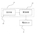
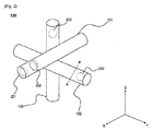
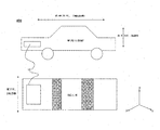
図1には、本発明に係る補助発電機が模式的に示されており、図2には、図1の固定管が具体的に示されており、図3には、図2のA−A’線に沿う固定管の垂直断面が示されており、図4には、図2の発電ベアリングが具体的に示されており、図5には、本発明に係る補助発電機が搭載された車両が示されている。 FIG. 1 schematically shows an auxiliary generator according to the present invention, FIG. 2 specifically shows the fixed pipe of FIG. 1, and FIG. A vertical section of the fixed tube along the line A ′ is shown, FIG. 4 specifically shows the power generation bearing of FIG. 2, and FIG. 5 is equipped with the auxiliary generator according to the present invention. The vehicle is shown.
まず、図1乃至図3を共に参照すると、補助発電機10は、固定管100、固定管100の内面に装着された圧電素子210、固定管100の内部に装着された発電ベアリング300、固定管100の内部で運動する慣性球体201,202,203、及び圧電素子210と発電ベアリング300から摩擦電気を収容して電気に変換する変換器120で構成されている。
1 to 3, the
図1に示したように、固定管の内部で慣性球体201,202,203が運動しながら圧電素子と発電ベアリング300が発生させた電気は、これらに電気的に接続された変換器120に移送され、変換器120は、収容した電気を電池セル20を充電できる電流に変換し、一定の電圧で電池セル20を充電する。
As shown in FIG. 1, the electricity generated by the piezoelectric element and the power generation bearing 300 while the
図2乃至図5を共に参照すると、固定管100は、それぞれ異なる方向に向かう第1管101、第2管102及び第3管103からなっている。
2 to 5, the fixed
具体的に、第1管101は、車両400の幅方向に水平なX軸に向かう状態で、第2管102及び第3管103と直交する形態で結合されており、第2管102は、車両400の長手方向に水平なY軸に向かう状態で、第1管101及び第3管103と直角をなす状態で結合されており、第3管103は、車両400の高さ方向に水平なZ軸に向かう状態で、第1管101及び第2管102と直角をなす状態で結合されている。
Specifically, the
以下では、説明の便宜上、図2での一つの発電ベアリング300、及び第2管を例に挙げて圧電素子210を示したが、これは例示的なもので、前記発電ベアリング300は、第1管101〜第3管103にそれぞれ2つ以上装着されており、第1管〜第3管の内面全体に圧電素子が装着されてもよいことは勿論であり、各管の長さ及び所望の電気的エネルギー量を考慮して、発電ベアリング300及び圧電素子210を弾力的に配置することができる。
In the following, for convenience of explanation, the
第1管101の内部には圧電素子(図示せず)及び発電ベアリング300が装着されており、第1管101に沿ってX軸方向に運動するように慣性球体201が内蔵されている。第2管102の内部には圧電素子210及び発電ベアリング(図示せず)が装着されており、第2管102に沿ってY軸方向に運動するように慣性球体202が内蔵されている。第3管103の内部には圧電素子(図示せず)及び発電ベアリング(図示せず)が装着されており、第3管103に沿ってZ軸方向に運動するように慣性球体203が内蔵されている。
A piezoelectric element (not shown) and a power generation bearing 300 are mounted inside the
発電ベアリング300は、リング状からなる一対の固定部302,304の間に多数の発電球体308が回転軸(図示せず)に装着されている構造となっている。リング状の発電ベアリング300は、慣性球体201が通過できるように開口310が形成されており、開口310の内部に発電球体308の一部が突出している。したがって、慣性球体201が発電ベアリング300の開口310を通過するとき、突出した発電球体308が慣性球体201と接触し、慣性球体201の運動方向の対向方向への回転力を得て回転するようになる。このとき、発電球体308が回転しながら、回転軸と摩擦電気を発生させる。
The power generation bearing 300 has a structure in which a large number of
一方、図5に示された車両400は補助発電機10を車両の内部に含んでおり、車両400の幅方向であるX軸方向(左側又は右側)に運動する場合、第1管101に内蔵された慣性球体201は、車両400の運動方向の対向方向に慣性力を得ることで第1管101内で運動するようになる。このとき、慣性球体201が運動しながら、圧電素子を進行方向に沿って押圧するようになり、圧電素子は、瞬間的に圧力が変化することによって電気を生産する。また、慣性球体は、発電ベアリング300の発電球体308を回転させ、発電球体308の回転運動が電気的エネルギーに変換される。
On the other hand, the
また、車両400の長手方向であるY軸方向に加速又は減速運動する場合、第2管102に内蔵された慣性球体は、車両400の加速又は減速に伴い、加速又は減速方向の対向方向に慣性力を得て運動するようになり、このとき、慣性球体202が運動しながら、圧電素子を進行方向に沿って押圧するようになり、圧電素子は、瞬間的に圧力が変化することによって電気を生産する。また、慣性球体202は、発電ベアリング(図示せず)の発電球体(図示せず)を回転させ、発電球体(図示せず)の回転運動が電気的エネルギーに変換される。
In addition, when the
同様に、車両400の高さ方向であるZ軸方向に車両400が上向きに運動する場合、第3管103に内蔵された慣性球体203は、下向きに慣性力を得て運動するようになり、Z軸方向に車両400が下向きに運動する場合、慣性球体203は、上向きに慣性力を得て運動するようになることによって、慣性球体が圧電素子及び発電ベアリングに圧力及び回転力を提供して電気を生産することができる。同時に、車両400が上向き又は下向きに運動する場合に、第1管101及び第2管102の慣性球体201,202は、第1管101及び第2管102の内部で車両400の運動方向に沿って上向き又は下向きに激しく揺れながら圧電素子210に圧力を印加し、それによって、圧電素子210が電気的エネルギーを発生させることができる。
Similarly, when the
以上、図面を参照して説明したように、本発明に係る補助発電機は、車両の運行による運動エネルギーで固定管の内部の慣性球体が運動するようにし、この慣性球体の運動で圧電素子及び発電ベアリングを通じて電気的エネルギーを発生させるため、車両の運行と同時に電気的エネルギーを得ることができる構造的特徴を有する。したがって、本発明に係る補助発電装置は、電気を用いる車両の運行距離を増加させることができる。 As described above with reference to the drawings, the auxiliary generator according to the present invention causes the inertial sphere inside the fixed tube to move with the kinetic energy due to the operation of the vehicle, and the movement of the inertial sphere causes the piezoelectric element and Since the electric energy is generated through the power generation bearing, the electric energy can be obtained simultaneously with the operation of the vehicle. Therefore, the auxiliary power generator according to the present invention can increase the travel distance of a vehicle using electricity.
本発明の属する分野における通常の知識を有する者であれば、上記内容に基づいて本発明の範疇内で様々な応用及び変形を行うことが可能であろう。 A person having ordinary knowledge in the field to which the present invention belongs can make various applications and modifications within the scope of the present invention based on the above contents.
以上で説明したように、本発明に係る補助発電機は、車両の運行による運動エネルギーを、前述した特別な構造を通じて電気的エネルギーに変換できるところ、車両の運行と同時に電気的エネルギーを得ることができ、それによって、バッテリーを持続的に充電することができるので、車両の走行距離を改善することができる。 As described above, the auxiliary generator according to the present invention can convert the kinetic energy from the operation of the vehicle into the electric energy through the special structure described above, and can obtain the electric energy simultaneously with the operation of the vehicle. Thus, the battery can be continuously charged, so that the mileage of the vehicle can be improved.
10 補助発電機
20 電池セル
100 固定管
101 第1管
102 第2管
103 第3管
120 変換器
201 慣性球体
202 慣性球体
203 慣性球体
210 圧電素子
300 発電ベアリング
302 固定部
304 固定部
308 発電球体
310 開口
400 車両
10
Claims (20)
車両の運動による慣性力によって車両の運動方向の対向方向に運動する慣性球体と、
前記運動する慣性球体を内部に収容する1つ以上の固定管と、
前記固定管の内部に装着されており、前記慣性球体の運動によって電気的エネルギーを発生させる発電部材と、
前記発電部材に電気的に接続されており、前記発電部材から発生した電気的エネルギーを収容して利用可能な電気に変換する変換器と
を含むことを特徴とする、補助発電機。 An auxiliary generator for a vehicle that converts kinetic energy of a vehicle into electrical energy,
An inertia sphere that moves in a direction opposite to the direction of movement of the vehicle by the inertial force of the movement of the vehicle;
One or more fixed tubes that house the moving inertial spheres therein;
A power generation member mounted inside the fixed tube and generating electrical energy by movement of the inertial sphere;
An auxiliary generator, comprising: a converter that is electrically connected to the power generation member and that converts electrical energy generated from the power generation member into usable electricity.
Applications Claiming Priority (3)
| Application Number | Priority Date | Filing Date | Title |
|---|---|---|---|
| KR1020140117448A KR101709536B1 (en) | 2014-09-04 | 2014-09-04 | Auxiliary Generator for Vehicle of Generating Electrical Power through Inertial Force |
| KR10-2014-0117448 | 2014-09-04 | ||
| PCT/KR2015/006848 WO2016035989A1 (en) | 2014-09-04 | 2015-07-03 | Vehicle auxiliary generator for generating power through inertial force |
Publications (2)
| Publication Number | Publication Date |
|---|---|
| JP2017532929A true JP2017532929A (en) | 2017-11-02 |
| JP6483731B2 JP6483731B2 (en) | 2019-03-13 |
Family
ID=55397343
Family Applications (1)
| Application Number | Title | Priority Date | Filing Date |
|---|---|---|---|
| JP2016575661A Active JP6483731B2 (en) | 2014-09-04 | 2015-07-03 | Auxiliary generator for vehicles that produces power using inertial force |
Country Status (6)
| Country | Link |
|---|---|
| US (1) | US10305398B2 (en) |
| EP (1) | EP3151372B1 (en) |
| JP (1) | JP6483731B2 (en) |
| KR (1) | KR101709536B1 (en) |
| CN (2) | CN105406763B (en) |
| WO (1) | WO2016035989A1 (en) |
Families Citing this family (2)
| Publication number | Priority date | Publication date | Assignee | Title |
|---|---|---|---|---|
| KR101709536B1 (en) * | 2014-09-04 | 2017-02-23 | 주식회사 엘지화학 | Auxiliary Generator for Vehicle of Generating Electrical Power through Inertial Force |
| CN112583297B (en) * | 2020-11-25 | 2022-03-08 | 江苏科技大学 | Friction nanometer generator based on fiber sliding and preparation method thereof |
Citations (4)
| Publication number | Priority date | Publication date | Assignee | Title |
|---|---|---|---|---|
| JP2003061368A (en) * | 2001-08-17 | 2003-02-28 | Nec Tokin Ceramics Corp | Piezoelectric power-generating unit |
| JP2003209980A (en) * | 2001-11-12 | 2003-07-25 | Jigyo Sozo Kenkyusho:Kk | Oscillatory generator |
| JP2009240011A (en) * | 2008-03-26 | 2009-10-15 | Saitama Univ | Power generation device and luminous buoy |
| JP2015517072A (en) * | 2012-04-24 | 2015-06-18 | アクティエボラゲット・エスコーエッフ | Bearing with built-in power generation mechanism |
Family Cites Families (18)
| Publication number | Priority date | Publication date | Assignee | Title |
|---|---|---|---|---|
| CN85104971A (en) | 1985-06-22 | 1987-02-18 | 孙寅贵 | Efficient electric driving system resort to vehicle's jolt |
| US5801475A (en) * | 1993-09-30 | 1998-09-01 | Mitsuteru Kimura | Piezo-electricity generation device |
| KR950017769U (en) * | 1993-12-23 | 1995-07-22 | Electric generator using inertial object during acceleration and deceleration of vehicle | |
| JP2001320887A (en) * | 2000-05-08 | 2001-11-16 | Mg:Kk | Swinging generator |
| AU2001278697A1 (en) * | 2000-08-11 | 2002-02-25 | Ecchandes Inc. | Overlapping type piezoelectric stator, overlapping type piezoelectric acturator and applications thereof |
| JP2004187429A (en) * | 2002-12-04 | 2004-07-02 | Tokai Rika Co Ltd | Generator and tire inner pressure detection device |
| WO2007121382A2 (en) | 2006-04-14 | 2007-10-25 | Ciiis, Llc | Power generator having a plurality of arranged power generator units |
| US7777396B2 (en) * | 2006-06-06 | 2010-08-17 | Omnitek Partners Llc | Impact powered devices |
| KR100982212B1 (en) | 2008-06-24 | 2010-09-14 | (주)맥신 | Generatror for vehicle |
| JP2010035368A (en) | 2008-07-30 | 2010-02-12 | Ricoh Co Ltd | Piezoelectric power generator |
| JP2010196669A (en) * | 2009-02-27 | 2010-09-09 | Yuho:Kk | Wind turbine generator |
| JP2011069402A (en) * | 2009-09-24 | 2011-04-07 | Ntn Corp | Bearing device with power generation function, and bearing device for vehicle using the same |
| JP2011093505A (en) * | 2009-10-27 | 2011-05-12 | Jiro Sugimura | Mounted-type vibration power generation system |
| GB2484324A (en) * | 2010-10-07 | 2012-04-11 | Adnan Mansoor | Power generating apparatus for a vessel, eg a ship or boat |
| WO2013028092A1 (en) * | 2011-08-24 | 2013-02-28 | Dostiiari Nasir Nadir Ogly | Piezo-electric source of electrical energy for vehicles |
| US9425712B2 (en) * | 2011-09-16 | 2016-08-23 | Harmonic Drive Systems Inc. | Vibration power-generating strain wave gearing |
| GB201207987D0 (en) | 2012-05-04 | 2012-06-20 | Imp Innovations Ltd | Power generation device |
| KR101709536B1 (en) | 2014-09-04 | 2017-02-23 | 주식회사 엘지화학 | Auxiliary Generator for Vehicle of Generating Electrical Power through Inertial Force |
-
2014
- 2014-09-04 KR KR1020140117448A patent/KR101709536B1/en active IP Right Grant
-
2015
- 2015-07-03 US US15/323,296 patent/US10305398B2/en active Active
- 2015-07-03 JP JP2016575661A patent/JP6483731B2/en active Active
- 2015-07-03 EP EP15838248.1A patent/EP3151372B1/en active Active
- 2015-07-03 WO PCT/KR2015/006848 patent/WO2016035989A1/en active Application Filing
- 2015-08-20 CN CN201510516174.8A patent/CN105406763B/en active Active
- 2015-08-20 CN CN201520632013.0U patent/CN205070842U/en active Active
Patent Citations (4)
| Publication number | Priority date | Publication date | Assignee | Title |
|---|---|---|---|---|
| JP2003061368A (en) * | 2001-08-17 | 2003-02-28 | Nec Tokin Ceramics Corp | Piezoelectric power-generating unit |
| JP2003209980A (en) * | 2001-11-12 | 2003-07-25 | Jigyo Sozo Kenkyusho:Kk | Oscillatory generator |
| JP2009240011A (en) * | 2008-03-26 | 2009-10-15 | Saitama Univ | Power generation device and luminous buoy |
| JP2015517072A (en) * | 2012-04-24 | 2015-06-18 | アクティエボラゲット・エスコーエッフ | Bearing with built-in power generation mechanism |
Also Published As
| Publication number | Publication date |
|---|---|
| KR101709536B1 (en) | 2017-02-23 |
| US10305398B2 (en) | 2019-05-28 |
| EP3151372A1 (en) | 2017-04-05 |
| EP3151372B1 (en) | 2021-03-03 |
| CN205070842U (en) | 2016-03-02 |
| KR20160028677A (en) | 2016-03-14 |
| JP6483731B2 (en) | 2019-03-13 |
| US20170170750A1 (en) | 2017-06-15 |
| CN105406763A (en) | 2016-03-16 |
| CN105406763B (en) | 2018-10-12 |
| EP3151372A4 (en) | 2017-08-23 |
| WO2016035989A1 (en) | 2016-03-10 |
Similar Documents
| Publication | Publication Date | Title |
|---|---|---|
| Wang et al. | Self-powered wind sensor system for detecting wind speed and direction based on a triboelectric nanogenerator | |
| Han et al. | Si@ void@ C nanofibers fabricated using a self-powered electrospinning system for lithium-ion batteries | |
| CN105114503B (en) | Automobile energy-feedback type damper | |
| He et al. | 3D full-space triboelectric-electromagnetic hybrid nanogenerator for high-efficient mechanical energy harvesting in vibration system | |
| Balakrishnan et al. | Nanostructured ceramic oxides for supercapacitor applications | |
| KR101637809B1 (en) | Rear tray for vehicle having energy harvesting elements | |
| CN204985479U (en) | Car energy repayment bumper shock absorber | |
| JP6483731B2 (en) | Auxiliary generator for vehicles that produces power using inertial force | |
| CN104426425A (en) | Inertial power generation device with power generating unit and acceleration direction detection device | |
| Tang et al. | A hybrid kinetic energy harvester for applications in electric driverless buses | |
| CN203554326U (en) | Friction power generator | |
| US20170028835A1 (en) | Electric Vehicle | |
| JP2017501929A (en) | Energy harvesting system for vehicles | |
| CN106487269A (en) | A kind of TRT and the sea water generator including this TRT | |
| CN108448939B (en) | composite piezoelectric-thermoelectric automobile exhaust micro energy collector | |
| JP2013048536A (en) | Linear power generation device | |
| KR101217128B1 (en) | Self-generation appatarus for automobile | |
| CN205498652U (en) | Electric automobile increases journey device | |
| US10848046B2 (en) | Electro-magnetic generator for vehicle and power plant | |
| KR20170018702A (en) | Apparatus for generating of electric power | |
| KR102383661B1 (en) | Electric Generating System Using Vehicle Wheel Tire | |
| CN101077691A (en) | Walking device | |
| Trzaska | Effective harvesting of braking energy in electric cars | |
| CN101633299A (en) | Method for absorbing and utilizing vibration energy and power energy | |
| WO2024070681A1 (en) | Electric vehicle |
Legal Events
| Date | Code | Title | Description |
|---|---|---|---|
| A977 | Report on retrieval |
Free format text: JAPANESE INTERMEDIATE CODE: A971007 Effective date: 20180523 |
|
| A131 | Notification of reasons for refusal |
Free format text: JAPANESE INTERMEDIATE CODE: A131 Effective date: 20180528 |
|
| A521 | Request for written amendment filed |
Free format text: JAPANESE INTERMEDIATE CODE: A523 Effective date: 20180815 |
|
| TRDD | Decision of grant or rejection written | ||
| A01 | Written decision to grant a patent or to grant a registration (utility model) |
Free format text: JAPANESE INTERMEDIATE CODE: A01 Effective date: 20190121 |
|
| A61 | First payment of annual fees (during grant procedure) |
Free format text: JAPANESE INTERMEDIATE CODE: A61 Effective date: 20190214 |
|
| R150 | Certificate of patent or registration of utility model |
Ref document number: 6483731 Country of ref document: JP Free format text: JAPANESE INTERMEDIATE CODE: R150 |
|
| R250 | Receipt of annual fees |
Free format text: JAPANESE INTERMEDIATE CODE: R250 |
|
| S111 | Request for change of ownership or part of ownership |
Free format text: JAPANESE INTERMEDIATE CODE: R313111 |
|
| R350 | Written notification of registration of transfer |
Free format text: JAPANESE INTERMEDIATE CODE: R350 |
|
| R250 | Receipt of annual fees |
Free format text: JAPANESE INTERMEDIATE CODE: R250 |
|
| R250 | Receipt of annual fees |
Free format text: JAPANESE INTERMEDIATE CODE: R250 |