JP2017528406A - Method of forming a molded glass article from a glass sheet - Google Patents
Method of forming a molded glass article from a glass sheet Download PDFInfo
- Publication number
- JP2017528406A JP2017528406A JP2017509647A JP2017509647A JP2017528406A JP 2017528406 A JP2017528406 A JP 2017528406A JP 2017509647 A JP2017509647 A JP 2017509647A JP 2017509647 A JP2017509647 A JP 2017509647A JP 2017528406 A JP2017528406 A JP 2017528406A
- Authority
- JP
- Japan
- Prior art keywords
- glass
- mold
- glass sheet
- article
- temperature
- Prior art date
- Legal status (The legal status is an assumption and is not a legal conclusion. Google has not performed a legal analysis and makes no representation as to the accuracy of the status listed.)
- Ceased
Links
Images


Classifications
-
- B—PERFORMING OPERATIONS; TRANSPORTING
- B32—LAYERED PRODUCTS
- B32B—LAYERED PRODUCTS, i.e. PRODUCTS BUILT-UP OF STRATA OF FLAT OR NON-FLAT, e.g. CELLULAR OR HONEYCOMB, FORM
- B32B17/00—Layered products essentially comprising sheet glass, or glass, slag, or like fibres
- B32B17/06—Layered products essentially comprising sheet glass, or glass, slag, or like fibres comprising glass as the main or only constituent of a layer, next to another layer of a specific material
- B32B17/10—Layered products essentially comprising sheet glass, or glass, slag, or like fibres comprising glass as the main or only constituent of a layer, next to another layer of a specific material of synthetic resin
-
- C—CHEMISTRY; METALLURGY
- C03—GLASS; MINERAL OR SLAG WOOL
- C03B—MANUFACTURE, SHAPING, OR SUPPLEMENTARY PROCESSES
- C03B23/00—Re-forming shaped glass
- C03B23/02—Re-forming glass sheets
- C03B23/023—Re-forming glass sheets by bending
- C03B23/035—Re-forming glass sheets by bending using a gas cushion or by changing gas pressure, e.g. by applying vacuum or blowing for supporting the glass while bending
- C03B23/0352—Re-forming glass sheets by bending using a gas cushion or by changing gas pressure, e.g. by applying vacuum or blowing for supporting the glass while bending by suction or blowing out for providing the deformation force to bend the glass sheet
-
- B32B17/064—
-
- B—PERFORMING OPERATIONS; TRANSPORTING
- B32—LAYERED PRODUCTS
- B32B—LAYERED PRODUCTS, i.e. PRODUCTS BUILT-UP OF STRATA OF FLAT OR NON-FLAT, e.g. CELLULAR OR HONEYCOMB, FORM
- B32B7/00—Layered products characterised by the relation between layers; Layered products characterised by the relative orientation of features between layers, or by the relative values of a measurable parameter between layers, i.e. products comprising layers having different physical, chemical or physicochemical properties; Layered products characterised by the interconnection of layers
- B32B7/04—Interconnection of layers
- B32B7/12—Interconnection of layers using interposed adhesives or interposed materials with bonding properties
-
- C—CHEMISTRY; METALLURGY
- C03—GLASS; MINERAL OR SLAG WOOL
- C03B—MANUFACTURE, SHAPING, OR SUPPLEMENTARY PROCESSES
- C03B23/00—Re-forming shaped glass
- C03B23/02—Re-forming glass sheets
- C03B23/023—Re-forming glass sheets by bending
- C03B23/0235—Re-forming glass sheets by bending involving applying local or additional heating, cooling or insulating means
-
- C—CHEMISTRY; METALLURGY
- C03—GLASS; MINERAL OR SLAG WOOL
- C03B—MANUFACTURE, SHAPING, OR SUPPLEMENTARY PROCESSES
- C03B23/00—Re-forming shaped glass
- C03B23/02—Re-forming glass sheets
- C03B23/023—Re-forming glass sheets by bending
- C03B23/035—Re-forming glass sheets by bending using a gas cushion or by changing gas pressure, e.g. by applying vacuum or blowing for supporting the glass while bending
- C03B23/0352—Re-forming glass sheets by bending using a gas cushion or by changing gas pressure, e.g. by applying vacuum or blowing for supporting the glass while bending by suction or blowing out for providing the deformation force to bend the glass sheet
- C03B23/0355—Re-forming glass sheets by bending using a gas cushion or by changing gas pressure, e.g. by applying vacuum or blowing for supporting the glass while bending by suction or blowing out for providing the deformation force to bend the glass sheet by blowing without suction directly on the glass sheet
-
- C—CHEMISTRY; METALLURGY
- C03—GLASS; MINERAL OR SLAG WOOL
- C03B—MANUFACTURE, SHAPING, OR SUPPLEMENTARY PROCESSES
- C03B23/00—Re-forming shaped glass
- C03B23/02—Re-forming glass sheets
- C03B23/023—Re-forming glass sheets by bending
- C03B23/035—Re-forming glass sheets by bending using a gas cushion or by changing gas pressure, e.g. by applying vacuum or blowing for supporting the glass while bending
- C03B23/0352—Re-forming glass sheets by bending using a gas cushion or by changing gas pressure, e.g. by applying vacuum or blowing for supporting the glass while bending by suction or blowing out for providing the deformation force to bend the glass sheet
- C03B23/0357—Re-forming glass sheets by bending using a gas cushion or by changing gas pressure, e.g. by applying vacuum or blowing for supporting the glass while bending by suction or blowing out for providing the deformation force to bend the glass sheet by suction without blowing, e.g. with vacuum or by venturi effect
-
- Y—GENERAL TAGGING OF NEW TECHNOLOGICAL DEVELOPMENTS; GENERAL TAGGING OF CROSS-SECTIONAL TECHNOLOGIES SPANNING OVER SEVERAL SECTIONS OF THE IPC; TECHNICAL SUBJECTS COVERED BY FORMER USPC CROSS-REFERENCE ART COLLECTIONS [XRACs] AND DIGESTS
- Y02—TECHNOLOGIES OR APPLICATIONS FOR MITIGATION OR ADAPTATION AGAINST CLIMATE CHANGE
- Y02P—CLIMATE CHANGE MITIGATION TECHNOLOGIES IN THE PRODUCTION OR PROCESSING OF GOODS
- Y02P40/00—Technologies relating to the processing of minerals
- Y02P40/50—Glass production, e.g. reusing waste heat during processing or shaping
- Y02P40/57—Improving the yield, e-g- reduction of reject rates
Landscapes
- Chemical & Material Sciences (AREA)
- Engineering & Computer Science (AREA)
- Materials Engineering (AREA)
- Organic Chemistry (AREA)
- Re-Forming, After-Treatment, Cutting And Transporting Of Glass Products (AREA)
- Surface Treatment Of Glass (AREA)
- Glass Compositions (AREA)
Abstract
ガラスシートから3Dガラス物品を成形する方法は、上記3Dガラス物品の3D表面プロファイルに対応する3D表面プロファイルを有する金型表面を含む金型組立体上に、ガラスシートを配置するステップを含む。上記ガラスシートは、成形温度まで加熱される。上記成形温度は、上記金型表面の温度より高い。加熱された上記ガラスシートは、上記金型表面に対向する上記ガラスシートの第1の表面に対して加圧ガスを印加することにより上記金型表面上に押し付けられ、これにより上記ガラスシートを上記金型表面に適合させ、このとき上記ガラスシートは、上記金型表面の温度を超える成形温度にある。A method of forming a 3D glass article from a glass sheet includes placing the glass sheet on a mold assembly that includes a mold surface having a 3D surface profile corresponding to the 3D surface profile of the 3D glass article. The glass sheet is heated to the molding temperature. The molding temperature is higher than the temperature of the mold surface. The heated glass sheet is pressed onto the mold surface by applying a pressurized gas to the first surface of the glass sheet facing the mold surface, whereby the glass sheet is Adapted to the mold surface, the glass sheet is now at a molding temperature that exceeds the temperature of the mold surface.
Description
本出願は、2014年8月20日出願の米国特許第62/039552号の優先権の利益を主張するものであり、上記特許の内容は参照によりその全体が本明細書に援用される。 This application claims the benefit of priority of US Patent No. 62/039552 filed Aug. 20, 2014, the contents of which are hereby incorporated by reference in their entirety.
本開示は、ガラスシートから成形ガラス物品を成形することに関する。 The present disclosure relates to molding molded glass articles from glass sheets.
ラップトップ、タブレット及びスマートフォンといった携帯電子デバイス用の、3次元(3D)ガラスカバーに対する需要が存在する。特に望ましい3Dガラスカバーは、ディスプレイとの対話のための2次元(2D)表面と、ディスプレイの縁部を包むための3D表面との組み合わせを有する。上記3D表面は非可展面、即ち歪曲させずに平面上へと開く又は広げることができない表面であり得、屈曲、角及び湾曲のいずれの組み合わせを含み得る。上記屈曲はきつく、かつ急であり得る。上記湾曲は不規則であり得る。このような3Dガラスカバーは、複雑であり、正確に作製することが困難である。 There is a need for three-dimensional (3D) glass covers for portable electronic devices such as laptops, tablets and smartphones. A particularly desirable 3D glass cover has a combination of a two-dimensional (2D) surface for interaction with the display and a 3D surface for wrapping the edges of the display. The 3D surface can be a non-developable surface, i.e., a surface that cannot be opened or expanded into a plane without distortion, and can include any combination of bends, corners, and curves. The bending can be tight and steep. The curvature can be irregular. Such a 3D glass cover is complicated and difficult to produce accurately.
例えば0.3mm超の比較的厚いガラスシートに関して、2Dガラスシートから3Dガラス物品を成形するために、熱改質が用いられている。熱改質は、2Dガラスシートを成形温度まで加熱し、その後上記2Dガラスシートを3D形状に改質することを伴う。2Dガラスシートを金型に対して落とし込む又は押圧することにより改質を行う場合、良好なガラス表面品質を維持するために、及びガラスと金型との反応を回避するために、ガラスの温度をガラスの軟化点未満に保つことが望ましい。軟化点未満では、ガラスは高い粘度を有し、屈曲、角及び湾曲等の複雑な形状に改質するために高圧を必要とする。従来のガラス熱改質においては、プランジャを用いて必要とされる高圧を印加する。プランジャはガラスに接触し、ガラスを金型に対して押圧する。 For example, for relatively thick glass sheets greater than 0.3 mm, thermal modification has been used to form 3D glass articles from 2D glass sheets. Thermal modification involves heating the 2D glass sheet to the molding temperature and then modifying the 2D glass sheet into a 3D shape. When modifying by dropping or pressing the 2D glass sheet against the mold, the glass temperature is set to maintain good glass surface quality and to avoid reaction between the glass and the mold. It is desirable to keep it below the softening point of the glass. Below the softening point, the glass has a high viscosity and requires high pressure to modify it into complex shapes such as bends, corners and curves. In the conventional glass thermal reforming, a required high pressure is applied using a plunger. The plunger contacts the glass and presses the glass against the mold.
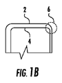
厚さが均一な3Dガラス物品を得るために、プランジャがガラスを金型に対して押圧する間、プランジャ表面と金型表面との間の間隙は均一でなければならない。図1Aは、プランジャ表面2と金型表面4との間の均一な間隙の例を示す。しかしながら、金型の機械加工における小さな誤差、及び金型とプランジャとの位置合わせ誤差により、プランジャ表面と金型表面との間の間隙が均一でないことが多い。図1Bは、プランジャの金型との位置合わせ不良による、プランジャ表面2と金型表面4との間の不均一な間隙(例えば8)を示す。
In order to obtain a 3D glass article of uniform thickness, the gap between the plunger surface and the mold surface must be uniform while the plunger presses the glass against the mold. FIG. 1A shows an example of a uniform gap between the
不均一な間隙は、ガラスの一部の領域における過度の押圧、及びガラスの他の領域における不十分な押圧をもたらす。過度の押圧は、3Dガラス物品における顕著な光学的歪みとして現れ得るガラスの薄化を引き起こし得る。不十分な押圧は、3Dガラス中に、特に、屈曲、角及び湾曲を含むガラス物品の複雑な領域に、しわを引き起こし得る。例えば10マイクロメートル程度の小さな機械加工誤差は、過度な押圧及び/又は不十分な押圧を生成することになる不均一な間隙をもたらし得る。また、プランジャ表面、金型表面、又は成形に関与する他の機器の回避できない熱膨張も、間隙の均一性に影響を及ぼし得る。押圧中、プランジャはまたガラスを伸展させ得、これにより、プランジャ表面と金型表面との間のガラスの厚さが変化する。従って、たとえプランジャ表面と金型表面との間の間隙が完璧であったとしても、ガラスの伸展が、厚さが不均一な3Dガラスをもたらし得る。金型表面又はプランジャ表面は、伸展の結果としての、ガラスの厚さの予期される変化を補償するよう設計してよい。しかしながらこれは、プランジャ表面と金型表面との間の不均一な間隙をもたらし得、これは上述の通り、ガラスの一部の領域における過度の押圧、及びガラスの他の領域における不十分な押圧をもたらし得る。 A non-uniform gap results in excessive pressing in some areas of the glass and insufficient pressing in other areas of the glass. Excessive pressing can cause glass thinning that can manifest as significant optical distortion in 3D glass articles. Insufficient pressing can cause wrinkles in 3D glass, especially in complex areas of the glass article including bends, corners and curvatures. Machining errors as small as 10 micrometers, for example, can result in non-uniform gaps that will produce excessive and / or insufficient pressure. In addition, unavoidable thermal expansion of the plunger surface, mold surface, or other equipment involved in molding can also affect the uniformity of the gap. During pressing, the plunger can also stretch the glass, which changes the glass thickness between the plunger surface and the mold surface. Thus, even if the gap between the plunger surface and the mold surface is perfect, glass stretching can result in 3D glass with non-uniform thickness. The mold surface or plunger surface may be designed to compensate for the expected change in glass thickness as a result of stretching. However, this can result in a non-uniform gap between the plunger surface and the mold surface, which, as described above, is excessive pressing in some areas of the glass and insufficient pressing in other areas of the glass. Can bring
従って、2Dシートから3Dガラス物品を確実に成形する方法であって、特に2Dシートが、厚さが約0.3mm以下の極薄フレキシブルガラスで成形されている、方法に関するニーズが存在する。 Accordingly, there is a need for a method for reliably forming a 3D glass article from a 2D sheet, particularly where the 2D sheet is formed from ultrathin flexible glass having a thickness of about 0.3 mm or less.
本明細書で開示する成形プロセスは、光学的歪み及び厳しい寸法制御なしに、ガラスシート(例えばフレキシブルガラスシート)から高品質な非可展形状を成形することを可能とする。引っかき及び摩耗保護等の様々な特性を提供するために、これらの3Dガラス物品の片側又は両側にプラスチックを積層できる。 The molding process disclosed herein allows high quality non-developable shapes to be molded from glass sheets (eg, flexible glass sheets) without optical distortion and tight dimensional control. Plastics can be laminated on one or both sides of these 3D glass articles to provide various properties such as scratch and wear protection.
ガラスは典型的には、プラスチック材料よりも良好な耐引っかき性及び耐摩耗性を有する。ガラスはまた、プラスチック材料と比較して、表面の損傷なしに容易に清掃でき、物体が、プラスチック内に埋まることができるようにはガラス内に埋まることがない。サンバイザー、サングラス、スキー用ゴーグル、度付きゴーグル等のような多数の透明ポリマー製品は非可展形状であり、ポリカーボネート又は同様の材料から作製される。本明細書で開示するように、ガラスシートをこのような非可展形状に成形して、プラスチック材料を積層することにより、完成した物品の寿命、透明度及びメンテナンスを向上させることができる。3D物品はまた、屈曲OLEDディスプレイ又は他の電子製品を成形するために使用してよい。 Glass typically has better scratch and abrasion resistance than plastic materials. Glass is also easier to clean without damaging the surface compared to plastic materials, and objects are not embedded in the glass so that they can be embedded in plastic. Many transparent polymer products, such as sun visors, sunglasses, ski goggles, prescription goggles, etc., are non-developable shapes and are made from polycarbonate or similar materials. As disclosed herein, the life, transparency and maintenance of the finished article can be improved by molding the glass sheet into such a non-developable shape and laminating the plastic material. The 3D article may also be used to shape a bent OLED display or other electronic product.
更なる特徴及び利点は、以下の「発明を実施するための形態」に記載され、またその一部は、「発明を実施するための形態」から当業者には容易に明らかとなり、又は本説明及び添付の図面に例示されているような実施形態を実施することによって認識されるだろう。以上の「発明の概要」及び以下の「発明を実施するための形態」はいずれも、開示される主題の単なる例であり、請求される主題の性質及び特徴を理解するための概観又は枠組みを提供することを意図したものであることを理解されたい。 Additional features and advantages are described below in the Detailed Description, some of which will be readily apparent to those skilled in the art from the Detailed Description, or the description And an embodiment as illustrated in the accompanying drawings will be appreciated. Both the foregoing "Summary of Invention" and the following "Mode for Carrying Out the Invention" are merely examples of the disclosed subject matter and provide an overview or framework for understanding the nature and characteristics of the claimed subject matter. It should be understood that it is intended to be provided.
添付の図面は、本開示の原理の更なる理解を提供するために含まれているものであり、本明細書に組み込まれて本明細書の一部を構成する。図面は1つ又は複数の実施形態を図示しており、本説明と併せて、本記事の原理及び動作を例として説明する役割を果たす。本明細書及び図面において開示される実施形態の様々な特徴は、いずれのあらゆる組み合わせで使用できることを理解されたい。非限定的な例として、本開示のこれら様々な特徴は、以下の態様に従って互いに組み合わせてよい。 The accompanying drawings are included to provide a further understanding of the principles of the disclosure and are incorporated in and constitute a part of this specification. The drawings illustrate one or more embodiments and, together with this description, serve to illustrate the principles and operations of this article. It should be understood that the various features of the embodiments disclosed herein and in the drawings can be used in any combination. By way of non-limiting example, these various features of the present disclosure may be combined with each other according to the following aspects.
第1の態様によると、ガラスシートから3Dガラス物品を成形する方法が提供され、上記方法は、上記3Dガラス物品の3D表面プロファイルに対応する3D表面プロファイルを有する金型表面を含む金型組立体上に、ガラスシートを配置するステップを含む。上記ガラスシートは、成形温度まで加熱される。上記成形温度は、上記金型表面の温度より高い。加熱された上記ガラスシートは、上記金型表面に対向する上記ガラスシートの第1の表面に対して加圧ガスを印加することにより上記金型表面上に押し付けられ、これにより上記ガラスシートを上記金型表面に適合させ、このとき上記ガラスシートは、上記金型表面の温度を超える成形温度にある。 According to a first aspect, a method for forming a 3D glass article from a glass sheet is provided, the method comprising a mold assembly comprising a mold surface having a 3D surface profile corresponding to the 3D surface profile of the 3D glass article. There is a step of placing a glass sheet on top. The glass sheet is heated to the molding temperature. The molding temperature is higher than the temperature of the mold surface. The heated glass sheet is pressed onto the mold surface by applying a pressurized gas to the first surface of the glass sheet facing the mold surface, whereby the glass sheet is Adapted to the mold surface, the glass sheet is now at a molding temperature that exceeds the temperature of the mold surface.
第2の態様によると、上記ガラスシートが、約0.3mm以下の厚さを備えるフレキシブルガラスシートである態様1の方法が提供される。
According to a second aspect, there is provided the method of
第3の態様によると、上記加熱されたガラスシートを上記金型表面上に押し付ける上記ステップが、上記第1の表面に対向する上記ガラスシートの第2の表面に真空を印加するステップを含む態様1又は態様2の方法が提供される。
According to a third aspect, the step of pressing the heated glass sheet onto the mold surface includes a step of applying a vacuum to the second surface of the glass sheet facing the first surface. A method of 1 or
第4の態様によると、上記加圧ガスが加熱される態様1〜3のいずれか1つの方法が提供される。 According to the 4th aspect, the method of any one of the aspects 1-3 with which the said pressurized gas is heated is provided.
第5の態様によると、上記方法が更に、圧力キャップ組立体を用いて上記金型組立体を密閉して、上記圧力キャップ組立体と上記金型組立体との間に加圧チャンバを形成するステップを含み、上記加圧ガスは約10psi〜約60psiである態様1〜4のいずれか1つの方法が提供される。 According to a fifth aspect, the method further includes sealing the mold assembly with a pressure cap assembly to form a pressurized chamber between the pressure cap assembly and the mold assembly. A method according to any one of aspects 1-4, wherein the pressurized gas is from about 10 psi to about 60 psi.
第6の態様によると、上記方法が更に、上記圧力キャップ組立体を約800℃〜約950℃の温度まで加熱し、これによって上記ガラスシートを放射加熱するステップを含む態様5の方法が提供される。
According to a sixth aspect, there is provided the method of
第7の態様によると、上記ガラスシートの成形温度が、上記加熱されたガラスシートを上記金型表面上に押し付ける上記ステップの間、上記金型表面の温度より少なくとも約25℃高い態様1〜6のいずれか1つの方法が提供される。 According to a seventh aspect, aspects 1-6, wherein the molding temperature of the glass sheet is at least about 25 ° C. higher than the temperature of the mold surface during the step of pressing the heated glass sheet onto the mold surface. Any one of the methods is provided.
第8の態様によると、上記ガラスシートの成形温度が、上記加熱されたガラスシートを上記金型表面上に押し付ける上記ステップの間、上記金型表面の温度より約25℃〜約100℃高い態様1〜7のいずれか1つの方法が提供される。 According to an eighth aspect, the molding temperature of the glass sheet is about 25 ° C. to about 100 ° C. higher than the temperature of the mold surface during the step of pressing the heated glass sheet onto the mold surface Any one method of 1-7 is provided.
第9の態様によると、上記方法が更に、上記加熱されたガラスシートを上記金型表面上に押し付ける上記ステップの後に、上記ガラスシートを冷却して、上記3Dガラス物品を成形するステップを含む態様1〜8のいずれか1つの方法が提供される。 According to a ninth aspect, the method further comprises the step of cooling the glass sheet to form the 3D glass article after the step of pressing the heated glass sheet onto the mold surface. Any one method of 1-8 is provided.
第10の態様によると、上記方法が更に、上記3Dガラス物品にポリマー層を塗布するステップを含む態様1〜9のいずれか1つの方法が提供される。 According to a tenth aspect, there is provided the method of any one of aspects 1-9, wherein the method further comprises applying a polymer layer to the 3D glass article.
第11の態様によると、ガラスシートから3Dガラス物品を成形するための装置が提供され、上記装置は、上記3Dガラス物品の3D表面プロファイルに対応する3D表面プロファイルを有する金型表面を有する、金型組立体を含む。圧力キャップ組立体は、上記金型組立体に係合して、上記圧力キャップ組立体と上記金型組立体との間に加圧キャビティを提供する。上記圧力キャップ組立体は、上記ガラスシートを上記金型表面の温度を超える成形温度まで加熱するよう構成されたヒータを含む。 According to an eleventh aspect, there is provided an apparatus for forming a 3D glass article from a glass sheet, the apparatus having a mold surface having a 3D surface profile corresponding to the 3D surface profile of the 3D glass article. Includes mold assembly. A pressure cap assembly engages the mold assembly to provide a pressurized cavity between the pressure cap assembly and the mold assembly. The pressure cap assembly includes a heater configured to heat the glass sheet to a molding temperature that exceeds the temperature of the mold surface.
第12の態様によると、上記ガラスシートが、0.3mm以下の厚さを有するフレキシブルガラスシートである態様11の装置が提供される。
According to a twelfth aspect, there is provided the apparatus according to
第13の態様によると、上記ヒータが、上記ガラスシートを上記金型表面の温度より少なくとも約25℃高い成形温度まで加熱するよう構成される態様11又は態様12の装置が提供される。
According to a thirteenth aspect, there is provided the apparatus of
第14の態様によると、上記ヒータが、上記フレキシブルガラスシートを上記金型表面の温度より約25℃〜約100℃高い成形温度まで加熱するよう構成される態様11〜13のうちのいずれか1つの装置が提供される。 According to a fourteenth aspect, any one of aspects 11-13, wherein the heater is configured to heat the flexible glass sheet to a molding temperature that is about 25 ° C. to about 100 ° C. higher than the temperature of the mold surface. One device is provided.
第15の態様によると、上記金型表面が金型キャビティを画定し、1つ又は複数のポートは、上記金型キャビティ内で負圧を印加するために、上記金型表面を横断する態様11〜14のうちのいずれか1つの装置が提供される。 According to a fifteenth aspect, the mold surface defines a mold cavity and the one or more ports traverse the mold surface to apply a negative pressure within the mold cavity. A device of any one of -14 is provided.
第16の態様によると、上記圧力キャップ組立体が、上記加圧ガスを受け取るためのプレナムチャンバを有するプレナムと、上記プレナムチャンバに隣接して設置され、上記金型表面から離間した流路構造体とを含む態様11〜15のうちのいずれか1つの装置が提供される。 According to a sixteenth aspect, the pressure cap assembly includes a plenum having a plenum chamber for receiving the pressurized gas, and a flow path structure disposed adjacent to the plenum chamber and spaced from the mold surface. The apparatus of any one of the aspects 11-15 containing these is provided.
第17の態様によると、上記圧力キャップ組立体が上記金型組立体から取り外し可能である態様11〜16のうちのいずれか1つの装置が提供される。 According to a seventeenth aspect, there is provided the apparatus of any one of aspects 11-16, wherein the pressure cap assembly is removable from the mold assembly.
第18の態様によると、ガラスシートから成形される3D物品が提供される。上記物品は、非平面構成を有するガラス層を含み、上記非平面構成は、上記3Dガラス物品の3D表面プロファイルに対応する3D表面プロファイルを有する金型表面を有する金型組立体を使用して成形される。上記ガラス層の表面にポリマー層を塗布し、ここで上記ガラス層は非平面構成である。上記ガラスシートは、上記金型表面の温度より高い成形温度において非平面構成へと成形される。 According to an eighteenth aspect, a 3D article molded from a glass sheet is provided. The article includes a glass layer having a non-planar configuration, wherein the non-planar configuration is molded using a mold assembly having a mold surface having a 3D surface profile corresponding to the 3D surface profile of the 3D glass article. Is done. A polymer layer is applied to the surface of the glass layer, where the glass layer has a non-planar configuration. The glass sheet is molded into a non-planar configuration at a molding temperature higher than the temperature of the mold surface.
第19の態様によると、上記ポリマー層が、上記ガラス層上にオーバモールドされるオーバモールド層である態様18の物品が提供される。 According to a nineteenth aspect, there is provided the article of aspect 18, wherein the polymer layer is an overmold layer overmolded onto the glass layer.
第20の態様によると、上記ポリマー層が上記ガラス層上に積層される態様18又は19の物品が提供される。 According to a twentieth aspect, there is provided the article of aspect 18 or 19, wherein the polymer layer is laminated on the glass layer.
第21の態様によると、上記物品が更に、上記ポリマー層と上記ガラス層との間に接着層を備える態様18〜20のうちのいずれか1つの物品が提供される。 According to a twenty-first aspect, there is provided the article according to any one of aspects 18 to 20, wherein the article further comprises an adhesive layer between the polymer layer and the glass layer.
第22の態様によると、上記ポリマー層が、上記ガラス層に圧縮応力を導入する態様18〜21のうちのいずれか1つの物品が提供される。 According to a twenty-second aspect, there is provided the article according to any one of aspects 18 to 21, wherein the polymer layer introduces compressive stress into the glass layer.
第23の態様によると、上記ガラス層が約0.3mm以下の厚さを有する態様18〜22のうちのいずれか1つの物品が提供される。 According to a twenty-third aspect, there is provided the article of any one of aspects 18-22, wherein the glass layer has a thickness of about 0.3 mm or less.
以下の「発明を実施するための形態」において、本開示の様々な原理の完全な理解を提供するために、説明を目的とし、限定を目的としない、具体的な詳細を開示する例示的な実施形態を示す。しかしながら、本開示の便益を得た当業者には、本開示は、本明細書で開示する具体的な詳細から逸脱した他の実施形態においても実施してよいことが明らかだろう。更に、周知のデバイス、方法及び材料の説明は、本開示の様々な原理の説明を不明瞭にしないために、省略する場合がある。最後に、可能な場合は常に、同様の参照符号は同様の要素を指す。 In the following Detailed Description, for purposes of explanation and not limitation, illustrative examples disclosing specific details in order to provide a thorough understanding of the various principles of the disclosure. An embodiment is shown. However, it will be apparent to those skilled in the art having the benefit of this disclosure that the present disclosure may be practiced in other embodiments that depart from the specific details disclosed herein. Moreover, descriptions of well-known devices, methods, and materials may be omitted so as not to obscure the description of various principles of the present disclosure. Finally, wherever possible, like reference numerals refer to like elements.
本明細書において範囲は、「約(about)」1つの特定の値から、及び/又は「約」別の特定の値までとして表すことができる。このような範囲が表される場合、別の実施形態は、上記1つの特定の値から、及び/又は上記別の特定の値までを含む。同様に、値が先行詞「約」の使用により近似値として表される場合、特定の値は別の実施形態を成形することが理解されるだろう。更に、各範囲の終点は、他方の終点に関して及び他方の終点とは関係なく重要であることが理解されるだろう。 Ranges herein may be expressed as from “about” one particular value and / or to “about” another particular value. When such a range is expressed, another embodiment includes from the one particular value and / or to the other particular value. Similarly, when values are expressed as approximations, by use of the antecedent “about,” it will be understood that the particular value forms another embodiment. Further, it will be appreciated that the end point of each range is important with respect to the other end point and independent of the other end point.
本明細書において使用する方向に関する用語(例えば上(up)、下(down)、右(right)、左(left)、前(front)、後ろ(back)、頂部(top)、底部(bottom))は、描かれた図面を参照してなされたものにすぎず、絶対的な配向を暗示することを意図していない。 Directional terms used herein (eg, up, down, right, left, front, back, top, bottom) ) Is only made with reference to the drawings, and is not intended to imply absolute orientation.
明示的に述べられている場合を除き、本明細書に示すいずれの方法が、該方法のステップをある具体的な順序で実施することを要求するものとして解釈されることは、全く意図されていない。従って、ある方法クレームが、その複数のステップが従うべき順序を実際に列挙していない、又はそうでなくても、上記複数のステップがある特定の順序に限定されることが請求項若しくは本説明において明示的に述べられていない場合、いかなる点においても、ある順序が推定されることは全く意図されていない。これは:ステップ又は操作フローの構成に関する論理の問題;文法構成又は句読法から引き出される単純な意味;明細書中に記載される実施形態の数又はタイプを含む、解釈に関するいずれの可能な非表現基準に対して成り立つ。 Except where expressly stated otherwise, any method presented herein is not intended to be construed as requiring that the steps of the method be performed in a specific order. Absent. Thus, the claims or the present description that a method claim does not actually enumerate the order in which the steps are to be followed, or is otherwise limited to a particular order. It is not intended that any order be inferred in any way unless explicitly stated in. This is: logic issues regarding the construction of steps or operational flows; simple meaning derived from grammar construction or punctuation; any possible non-representation regarding interpretation, including the number or type of embodiments described in the specification It holds for the standard.
本明細書において使用する場合、名詞は、文脈がはっきりと指示する場合を除き、複数の指示対象を指す。従って、例えばある「構成要素(component)」に対する言及は、文脈がはっきりと指示する場合を除き、2つ以上のこのような構成要素を有する複数の態様を含む。 As used herein, a noun refers to a plurality of referents unless the context clearly indicates otherwise. Thus, for example, reference to “a component” includes a plurality of aspects having two or more such components, unless the context clearly indicates otherwise.
フレキシブルガラス基板は、湾曲した又は適合性形状を、例として電子装置、包装及び建築用途において使用可能とすることができる。本明細書に記載される実施形態は一般に、
圧力キャップ組立体から送達される高温加圧ガスを使用して、2Dガラスシート(例えばフレキシブルガラスシート)から3Dガラス物品を成形することに関し、上記高温ガスは、成形プロセス中に上記ガラスシートの放射加熱を提供するために、金型温度より高い温度にある。高温加圧ガスをガラスシートに均一に印加してよく、又は差分を有して、例えば屈曲、角及び湾曲を含む上記ガラスシートの領域等の比較的高い成形圧力を必要とするガラスシートの領域に対して比較的高濃度で印加してよい。一般に、上記プロセスは:上記ガラスシートを金型組立体上に、金型キャビティを覆うように配置するステップ;上記圧力キャップ組立体(又は少なくともその一部分)を事前に選択した温度まで予熱し、上記圧力キャップ組立体からの放射加熱を用いて上記ガラスシートを加熱し、これによって、上記金型組立体が上記ガラスシートより冷たくなるように、上記ガラスシートと上記金型組立体との間に温度差を提供する、ステップ;高温加圧ガスを印加して、上記ガラス物品の3D形状を完成させるステップ;及び上記3Dガラス物品を冷却するステップを含んでよい。
Flexible glass substrates can allow curved or conformable shapes to be used in electronic devices, packaging and architectural applications, for example. The embodiments described herein are generally
With respect to forming a 3D glass article from a 2D glass sheet (eg, a flexible glass sheet) using hot pressurized gas delivered from a pressure cap assembly, the hot gas is emitted from the glass sheet during the forming process. To provide heating, be at a temperature above the mold temperature. Regions of the glass sheet that require a relatively high forming pressure, such as regions of the glass sheet that may be uniformly applied to the glass sheet or have a difference, for example, bends, corners, and curves May be applied at a relatively high concentration. In general, the process includes: placing the glass sheet on a mold assembly over a mold cavity; preheating the pressure cap assembly (or at least a portion thereof) to a preselected temperature; Radiation heating from the pressure cap assembly is used to heat the glass sheet, thereby causing the temperature between the glass sheet and the mold assembly so that the mold assembly is cooler than the glass sheet. Providing a difference; applying hot pressurized gas to complete the 3D shape of the glass article; and cooling the 3D glass article.
3Dガラス物品は一般に、非平面構成を有する。本明細書において使用する場合、用語「非平面構成(non−planar formation)」は、ガラス物品の少なくとも一部分が外向きに、又はフレキシブルガラスシートの元の展開構成によって画定されるある平面に対してある角度をなして延在する、3D形状を指す。ガラスシートから成形された上記3Dガラス物品は、1又は複数の隆起又は湾曲部分を有してよい。3Dガラス物品は、成形プロセスによるいずれの外力なしに、自立した物体として非平面構成を保持できる。 3D glass articles generally have a non-planar configuration. As used herein, the term “non-planar formation” refers to a plane in which at least a portion of the glass article is defined outwardly or by the original unfolded configuration of the flexible glass sheet. Refers to a 3D shape that extends at an angle. The 3D glass article formed from a glass sheet may have one or more raised or curved portions. The 3D glass article can hold a non-planar configuration as a free-standing object without any external force due to the molding process.
いくつかの実施形態では、ガラスシートは、フレキシブルガラスシートである。本明細書に記載するフレキシブルガラスシートは、例えば0.3、0.275、0.25、0.225、0.2、0.19、0.18、0.17、0.16、0.15、0.14、0.13、0.12、0.11、0.10、0.09、0.08、0.07、0.06、0.05、0.04、0.03、0.02、又は0.01mmを含む、約0.01〜0.05mm、約0.05〜0.1mm、約0.1〜0.15mm、約0.15〜0.3mmを含むがこれらに限定されない約0.3mm以下の厚さを有してよい。このガラスシートは、ガラス、ガラスセラミック、セラミック材料又はこれらの複合体で成形してよい。言及する際の便宜のためだけに、用語「フレキシブルガラスシート」「ガラス層」又は「フレキシブルガラス基板」を明細書全体で使用する場合があるが、このような基板又は層は代わりにこれらの材料のうちのいずれから作製できる。高品質ガラス基板を成形するフュージョンプロセス(例えばダウンドロープロセス)を用いて、ガラスシートを成形できる。フュージョンプロセスにおいて製造されたガラスシートは、他の方法で製造されたガラスシートと比べて、優れた平坦性及び平滑性を有する表面を有し得る。フュージョンプロセスは、米国特許第3,338,696号明細書及び第3,682,609号明細書に記載されている。他の好適なガラス基板成形方法としては、フロートプロセス、アップドロー及びスロットドロー法が挙げられる。 In some embodiments, the glass sheet is a flexible glass sheet. The flexible glass sheet described in the present specification is, for example, 0.3, 0.275, 0.25, 0.225, 0.2, 0.19, 0.18, 0.17, 0.16,. 15, 0.14, 0.13, 0.12, 0.11, 0.10, 0.09, 0.08, 0.07, 0.06, 0.05, 0.04, 0.03, Including about 0.01-0.05 mm, about 0.05-0.1 mm, about 0.1-0.15 mm, about 0.15-0.3 mm, including 0.02 or 0.01 mm It may have a thickness of not more than about 0.3 mm. The glass sheet may be formed of glass, glass ceramic, ceramic material or a composite thereof. For the sake of convenience only, the terms “flexible glass sheet”, “glass layer” or “flexible glass substrate” may be used throughout the specification, but such a substrate or layer is instead used in these materials. Can be made from any of these. A glass sheet can be formed using a fusion process (eg, a downdraw process) that forms a high quality glass substrate. A glass sheet produced in a fusion process may have a surface with superior flatness and smoothness as compared to glass sheets produced by other methods. The fusion process is described in US Pat. Nos. 3,338,696 and 3,682,609. Other suitable glass substrate forming methods include a float process, an up draw and a slot draw method.
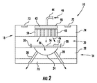
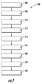
図2を参照すると、2Dフレキシブルガラスシート12から3Dガラス物品を成形するための方法及び装置10が示されている。装置10は、金型組立体14及び圧力キャップ組立体16を含み、上記圧力キャップ組立体16は、金型組立体14に接続されて、圧力キャップ組立体16と金型組立体14との間に加圧成形キャビティ20を成形する。金型組立体14は、成形されることになるガラス物品の所望の3D形状に対応する3D表面プロファイルを有する金型表面24を有する。金型表面24は、凹状であり、金型キャビティ26を画定するものとして示されているが、凸状、凸凹、平坦、及び湾曲領域等といった他の形状を使用してよい。フレキシブルガラスシート12は、金型本体22上の、金型キャビティ26の中に又は金型表面24に対して落とし込まれる位置に配置される。ポート又は孔28を金型本体22に設けてよい。ポート28は、金型本体22から金型表面24まで延在してよい。一実施形態では、ポート28は、金型表面24の角に配置される。他の実施形態では、ポート28は、金型表面24の角及び底部に、又は金型表面24の底部だけに配置してよい。ポート28は、金型キャビティ26に真空を印加するための真空ポートとして、又は金型キャビティ26内に閉じ込められたガスを取り出すための排出ポートとして機能できる。金型本体22上に位置合わせピン30を設けて、フレキシブルガラスシート12の金型キャビティ20との位置合わせを支援してよい。
Referring to FIG. 2, a method and
金型本体22は、例えばフレキシブルガラスシートからガラス物品を成形する間に直面することになる高温に耐えることができる材料で作製してよい。金型材料は、成形条件下でガラスと反応しない(若しくはガラスに粘着しない)材料であってよく、又は金型表面24は、成形条件下でガラスと反応しない(若しくはガラスに粘着しない)コーティング材料でコーティングしてよい。一実施形態では、金型本体22はグラファイト等の非反応性炭素材料で作製され、金型表面24は、金型表面24がガラスと接触した場合にガラスに欠陥が導入されることを回避するために高度に研磨される。別の実施形態では、金型本体22は、炭化ケイ素、炭化タングステン、及び窒化ケイ素等の高密度セラミック材料で作製され、金型表面24は、グラファイト等の非反応性炭素材料でコーティングされる。別の実施形態では、金型本体22は、Inconel 718、Inconel 600、ニッケル‐クロム合金等の超合金で作製され、金型表面24は、窒化チタンアルミニウム等の硬質セラミック材料でコーティングされる。一実施形態では、コーティング材料を備える又は備えない金型表面24は、約10nm以下の表面粗度Raを有する。金型本体22のために炭素材料が使用される、又は金型表面24のために炭素コーティング材料が使用される実施形態では、ガラス物品の成形は不活性雰囲気において実施できる。
The
圧力キャップ組立体16は、金型組立体14の頂部上に設置される。圧力キャップ組立体16が金型組立体14上に設置される場合、圧力キャビティ20は圧力キャップ組立体16と金型組立体14との間に成形される。圧力キャップ組立体16はプレナムチャンバ42を含むプレナム40を含み、上記プレナムチャンバ42は、導管44を介して、窒素又はいずれの他の好適なガスであってよい高温加圧ガス46源に接続される。圧力キャップ組立体16は、流路構造体48を含み、上記流路構造体48は、プレナムチャンバ42の下側に設置され、金型本体22の上方に位置決めされる。流路構造体48は、例えば流路50を含む穿孔されたプレートであってよく、上記流路50を通して、プレナムチャンバ42内の加圧ガス46を、圧力キャビティ20へと配向でき、また金型表面24に向かって配向できる。流路構造体48を含む圧力キャップ組立体16は、フレキシブルガラスシート12が成形物品へと改質される条件下で汚染物質を生成しない材料で成形してよい。
The
圧力キャビティ20は、プレナム40及び流路構造体48を通して圧力キャビティ20へと高温加圧ガス46を送達する前に、圧力キャップ組立体16と金型組立体14との間を密閉してよい。圧力キャビティ20は、圧力キャップ組立体16に対して力を印加することにより密閉してよく、これにより圧力キャップ組立体16は金型本体22の頂部に対して下向きに固定する。ラム又は他の好適なデバイスを使用して、力を印加してよい。密閉条件を維持するために、密閉用圧力は、圧力キャビティ20に送達される高温加圧ガス46の圧力より高くてよい。
The
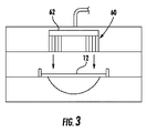
図示した実施形態では、流路構造体48は、プレナムチャンバ42の底部全体を占有し、フレキシブルガラスシート12の頂面56全体にわたって高温加圧ガス46を配向する。流路構造体48における孔の分布及びサイズが均一である場合、高温加圧ガス46は、フレキシブルガラスシート12の表面56全体にわたって略均一に配向される。図3は、流路構造体60がプレナムチャンバ62の縁部に配置され、フレキシブルガラスシート12の頂面56に対する高温加圧ガス46の、差分を有する印加を可能とする代替的配置を示す。流路構造体60の形状は環状であってよい。あるいは、プレナムチャンバ62の縁部に沿って配設された複数の流路構造体を使用してよい。図3に示す配置では、流路構造体60は、フレキシブルガラスシート12の周縁に高温加圧ガスを配向する。この周縁は高い成形圧力が必要である箇所、例えば屈曲、角又は湾曲が成形される箇所であり得る。一般に、プレナム上の流路構造体の位置は、流路構造体を通して送達される高温加圧ガスの焦点を決定し、流路構造体の配置、並びに流路構造体の間隔及び流路構造体における孔は、成形されることになる3D形状に合わせてよい。金型上のフレキシブルガラスシートの選択された領域に高温加圧ガスを配向する、又は金型本体上のフレキシブルガラスシートにわたって高温加圧ガスを、差分を有するように配向する、図3に示すような流路構造体は、指向性流路構造体と呼んでよい。
In the illustrated embodiment, the
いくつかの実施形態では、高温加圧ガス46を圧力キャビティ20内に送達する前に、圧力キャビティ20を密閉しなくてよい。図3における流路構造体60等の指向性流路構造体は、フレキシブルガラスシート12から短い距離(例えば約5mm以下)内に位置決めしてよい。上記短い距離は、高圧力成形を必要とするフレキシブルガラスシート12の所望の領域に限定される指向性流路構造体を通して印加される指向性ジェットを提供できる。この指向性ジェットの高い速度を用いて、フレキシブルガラスシート12の所望の領域内にポイント又はライン圧力を生成してよい。この場合圧力キャビティ20は密閉されていないため、圧力キャビティ20内の平衡圧力は確立されない。従ってフレキシブルガラスシート12の所望の領域のみが、高速ガス噴射圧力を受承できる。
In some embodiments, the
図2に示すように、金型組立体14は、真空チャック70上に配置してよい。他の実施形態では、真空チャック70を使用しなくてよい。加圧ガス46及び圧力キャップ本体74を加熱するために、加熱要素72を圧力キャップ組立体16に配置してよい。圧力キャップ本体74を加熱することにより、フレキシブルガラスシート12の放射加熱が可能となる。いくつかの実施形態では、ヒータは、直接的に、又は圧力キャップ本体74を通して間接的にフレキシブルガラスに放射熱を送達するよう位置決めされたIRヒータであってよい。いくつかの実施形態では、金型表面24において、フレキシブルガラスシート12と金型本体22との間に温度差が提供される。例えば上記温度差は、ガラス物品成形プロセス中、少なくとも約25℃、例えば少なくとも約50℃、例えば約25℃〜約100℃である。IR又は抵抗ヒータ等のいずれの好適なヒータを使用してよい。
As shown in FIG. 2, the
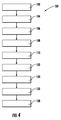
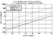
図4を参照すると、3Dガラス物品を成形する例示的な方法100が示されている。この実施形態では、フュージョンドロープロセス等のいずれの好適なプロセスを用いて、ステップ102において、連続的なフレキシブルガラスリボンを成形してよい。ステップ104において、レーザ切断、スコーリング及び破壊等のいずれの好適な切断プロセスを用いて、フレキシブルガラスシートを連続的なフレキシブルガラスリボンから取り外してよい。ステップ106において、例えば特に切断縁部における研磨、エッチング、縁部コーティング等によってフレキシブルガラスシートを縁部強化することが望ましい場合がある。ステップ108において、フレキシブルガラスシートを金型組立体14内に配置する前に、フレキシブルガラスシートを(例えば成形温度未満の温度に)予熱してよい。他の実施形態では、フレキシブルガラスシートを金型組立体14内で予熱してよい。ステップ110において、フレキシブルガラスシートを、金型組立体14と圧力キャップ組立体16との間の圧力キャビティ20内に配置してよい。いくつかの実施形態では、金型本体22上にフレキシブルガラスシートを配置する前に、金型本体22を予熱してよい。いくつかの実施形態では、位置合わせピン30を使用して、フレキシブルガラスシートを金型本体22上に配置してよい。フレキシブルガラスシートを金型上に配置した後、中赤外線加熱要素又はエミッタプレートを使用して、上述したように所望のガラスの粘度又は粘度範囲に対応する成形温度に、フレキシブルガラスシートを加熱してよい。金型組立体14はその後、圧力キャップ組立体16の下に移動される又は送られる。図5は、0.13mm、0.2mm及び0.7mm厚のガラスシートに関する、成形にかかる時間と、3mmの曲げ半径を有する皿形状のガラスの粘度との例示的な関係を示す。図に示すように、比較的薄いガラスシートは、比較的厚いガラスシートに比べて、より高い粘度で改質できる。
Referring to FIG. 4, an
一実施形態では、フレキシブルガラスシート及び金型本体22は、これらの両方が、フレキシブルガラスシートの3Dガラス物品への成形を開始する時点までに同一の温度となるように、加熱される。このタイプの加熱のために、金型本体22は、グラファイト等の非反応性炭素材料で、又は炭素コーティング材料でコーティングされた高密度セラミック材料で作製してよい。加熱は、不活性雰囲気において実施してよい。別の実施形態では、フレキシブルガラスシートを金型本体22上にある間に加熱してよく、これにより、金型本体22の温度はフレキシブルガラスシートの温度より低くなり、例えば金型本体22の温度はフレキシブルガラスシートの温度より25℃〜100℃低くなり得る。この加熱のために中赤外線ヒータを使用してよい。金型本体22は、硬質セラミックコーティングを有する超合金で作製してよい。この材料を用いた場合、加熱を不活性又は不活性でない雰囲気において実施できる。
In one embodiment, the flexible glass sheet and
フレキシブルガラスシート及び金型本体22を加熱した後、ステップ122において、金型キャビティ26に真空を印加して、フレキシブルガラスシートの底面を金型表面24に対して引き込み、フレキシブルガラスシートを金型表面24に対して密閉する。真空が印加される前に、フレキシブルガラスシートを既に、重力により金型表面24に対して落とし込み始めてよい。一実施形態では、印加される真空は、2〜10(Hg)の範囲で印加してよい。高温加圧ガス46は、プレナム40及び圧力チャンバ42を通して、部分的に成形されたフレキシブルガラスシートの頂面に対して印加される。高温加圧ガス46は、フレキシブルガラスシートを金型表面24に完全に適合させるのに必要な圧力を提供する。高温加圧ガスの温度は、107Poise(106Pa・s)〜1011Poise(1010Pa・s)のガラスの粘度範囲に対応する上述の温度範囲内である。圧力キャップ組立体16及び/又はN2温度が800℃超、例えば870℃〜950℃となることが望ましい場合があり、これにより、圧力成形中にフレキシブルガラスシートを放射加熱して、フレキシブルガラスシートを低粘度にとどめ、比較的速い速度で金型の形状に適合させることを可能とする。高温加圧ガスの温度は、フレキシブルガラスシートの温度と同一であっても、異なっていてもよい。一実施形態では、高温加圧ガスの温度は、フレキシブルガラスシートの温度の80℃以内である。高温加圧ガスの温度は、フレキシブルガラスシートの温度と同一であるか、又はこれより高いか、又は低くてよい。フレキシブルガラスシートの温度より高い温度における高温加圧ガスの噴出は、フレキシブルガラスシートに選択的に印加してよい。流路構造体60は、高温加圧ガスの噴出が指向的に、即ち噴出が必要なフレキシブルガラスシートの領域にのみ印加されるように設計してよい。3D形状を成形するためのガス圧力は、接触成形に用いられるプランジャ圧力に相当し得る。成形されることになる3D形状及びガラスの粘度に応じて、この圧力を10psi〜60psiの範囲内としてよい。
After heating the flexible glass sheet and the
既に上述したように、高温加圧ガス46をフレキシブルガラスシートに印加する前に、圧力キャビティ20を密閉してよい。フレキシブルガラスシートが圧力キャップ組立体16からの放射によって加熱される場合、フレキシブルガラスシートの加熱前、加熱中又は加熱後に、圧力キャビティ20を密閉してよい。あるいは、圧力キャビティ20が密閉されることになる場合、圧力キャビティ20は、フレキシブルガラスシートが放射を用いて金型本体22上で直接的に加熱される場合は、フレキシブルガラスシートの加熱後に密閉するべきである。高温加圧ガス46をフレキシブルガラスシートに印加する数秒前に、真空を金型キャビティ26に印加できる。高温加圧ガス46をガラスシートに印加する期間の一部又は全体にわたって真空を維持でき、この場合、真空は金型本体22上のフレキシブルガラスシートの位置を維持でき、これにより高温加圧ガス46が印加されたときにフレキシブルガラスシートは移動せず、また加圧ガスはフレキシブルガラスシートの真下を流れることができない。開始時のフレキシブルガラスシートが金型キャビティ26より大きく、これが金型キャビティ26を覆っている場合、真空を用いることなく、フレキシブルガラスシートを3Dガラス物品へと成形できる。真空を用いて又は用いずに成形する間、金型キャビティ26内のポートを使用して金型キャビティ26内に閉じ込められたガスを排出してよい。
As already mentioned above, the
3Dガラス物品を成形した後、ステップ130において、高温加圧ガス46の圧力キャビティ20への流れは、停止されるか、又は比較的低温の加圧ガス流に置き換えられる。続いて3Dガラス物品は、比較的低温の加圧ガスを用いて又は用いずに、アニール点付近まで冷却される。この比較的低温の加圧ガスは、3Dガラス物品のより急速な冷却を支援できる。一実施形態では、上記比較的低温の加圧ガスが3Dガラス物品の冷却に使用される場合、上記比較的低温の加圧ガスの温度は、ガラス転移温度プラス又はマイナス0℃に対応する温度範囲から選択される。別の実施形態では、上記比較的低温の加圧ガスが3Dガラス物品の冷却に使用される場合、上記比較的低温の加圧ガスの温度は、冷却中の金型本体22の温度に一致するよう調整される。これは、熱電対等のセンサを用いて金型本体22の温度を監視し、センサの出力を使用して上記比較的低温の加圧ガスの温度を調整することにより、達成してよい。上記比較的低温の加圧ガスの圧力は、高温加圧ガスの圧力未満であるか又はこれと同一であってよい。3Dガラス物品の冷却は、ガラス物品の厚さにわたる、ガラス物品の長さに沿った、及びガラス物品の幅に沿った温度差(デルタT)を、最小化するものである。また、金型組立体を加圧ガスによって冷却して、金型の冷却を加速してもよい。
After forming the 3D glass article, in
デルタTは、ガラス物品の厚さにわたり、並びにガラス物品の長さ及び幅に沿って10℃未満であってよい。冷却中のデルタTが小さくなればなるほど、ガラス物品内中の応力も低くなる。冷却中にガラス物品中に高い応力が生成された場合、ガラス物品は応力に応答して歪み得る。従って、冷却中にガラス物品中に高い応力が生成されることを回避することが望ましい場合がある。3Dガラス物品の両側に温度制御されたガス流を印加することにより、3Dガラス物品を対流冷却できる。上述のように、比較的低温の加圧ガスは、プレナム40及びプレナムチャンバ42を通して3Dガラス物品の頂面に印加でき、上記比較的低温の加圧ガスと同様の特性を有し得る温度制御されたガス流は、金型キャビティ26内のポートを通して3Dガラスの底面に印加できる。ポートを通して供給されたガスの圧力は、ステップ132における冷却中に3Dガラス物品を金型キャビティ26から持ち上げる正味の力が生成されるようなものであってよい。金型本体22は、金型本体22がガラスより大きな熱質量を有するため、ガラスより遥かに遅い速度で冷却できる。金型本体22のこの徐冷は、ガラスの厚さにわたって大きなデルタTを生成できる。冷却中にガラスを金型本体22から持ち上げることにより、この大きなデルタTを回避するのを助けることができる。
The Delta T may be less than 10 ° C. across the thickness of the glass article and along the length and width of the glass article. The smaller the delta T during cooling, the lower the stress in the glass article. If high stress is generated in the glass article during cooling, the glass article can be distorted in response to the stress. Thus, it may be desirable to avoid creating high stresses in the glass article during cooling. By applying a temperature-controlled gas stream to both sides of the 3D glass article, the 3D glass article can be convectively cooled. As mentioned above, a relatively cold pressurized gas can be applied to the top surface of the 3D glass article through the
緩やかな輪郭は、比較的高いガラスの粘度、例えば109Poise(108Pa・s)〜1011Poise(1010Pa・s)において成形でき、きつい屈曲及び鋭い角は比較的低い粘度107Poise(106Pa・s)〜108Poise(107Pa・s)において成形し得る。この比較的低い粘度により、ガラスは金型により良好に適合できる。しかしながら、低粘度では良好なガラス表面化粧を達成することが困難になり得る。というのは、これによりガラス表面により容易に欠陥が刻まれ得るためである。低粘度における成形は例えば、オレンジピールを生成し得るガラスの再沸騰を引き起こし得る。比較的低いガラスの粘度では、金型表面内の真空又は排出ポートをガラス中に押し込むことができる。その一方で、高いガラスの粘度では、良好な表面化粧を達成できる。従って、3Dガラスにおいて良好なガラス表面化粧及び厳しい寸法公差の両方を達成するために、高温加圧ガスによってガラスに印加される圧力、ガラスの粘度、及び上記高温加圧ガスの圧力が印加される場所を最適化できる。良好な表面化粧を維持しながら厳しい寸法公差を得るための、複数の選択肢が存在する。 The gentle contour can be molded at relatively high glass viscosities, such as 10 9 Poise (10 8 Pa · s) to 10 11 Poise (10 10 Pa · s), with tight bends and sharp corners having a relatively low viscosity of 10 7. Poise (10 6 Pa · s) to 10 8 Poise (10 7 Pa · s) can be formed. Due to this relatively low viscosity, the glass can be better adapted to the mold. However, low viscosity can make it difficult to achieve good glass surface makeup. This is because defects can be easily carved into the glass surface. Molding at low viscosity can cause, for example, reboiling of the glass that can produce orange peel. At relatively low glass viscosities, a vacuum or exhaust port in the mold surface can be forced into the glass. On the other hand, good surface makeup can be achieved at high glass viscosities. Thus, to achieve both good glass surface makeup and tight dimensional tolerances in 3D glass, the pressure applied to the glass by the hot pressurized gas, the viscosity of the glass, and the pressure of the hot pressurized gas are applied. You can optimize the location. There are multiple options for obtaining tight dimensional tolerances while maintaining good surface makeup.
1つの選択肢は、金型における輪郭補正を用いることであってよい。例えば、きつい屈曲を有する3D形状を成形するために、金型を、最終的な形状よりきつい曲げ半径及び急な側壁接線角度の壁を有して設計できる。例えば、成形されることになる皿の側壁接線角度が60°である場合、そして良好なガラス表面化粧を維持するために皿をlog粘度9.5において皿を成形することが望まれる場合、成形プロセスは、金型の輪郭が補正されない場合は側壁接線角度が46°の、即ち所望の角度より14°小さい皿を製造してよい。ガラスの粘度を低下させることなく側壁接線角度を増大させるために、金型の輪郭を補償して、理想の形状と成形された物品において測定された角度との差だけ、側壁接線角度を増大させることができる。上述の例では、補償された金型は74°の側壁接線角度を有し得る。形状を成形するために必要な圧力が高温加圧ガスによって提供されていることにより、懸念すべきプランジャと金型との間隙が存在しないため、この輪郭補正を行うこと、及び厚さが均一なガラス物品を達成することが可能である。 One option may be to use contour correction in the mold. For example, to mold a 3D shape with tight bends, the mold can be designed with walls with tighter bend radii and steep sidewall tangent angles than the final shape. For example, if the side wall tangent angle of the dish to be molded is 60 ° and if it is desired to mold the dish at a log viscosity of 9.5 to maintain a good glass surface makeup The process may produce a dish with a side wall tangent angle of 46 ° if the mold profile is not corrected, ie, 14 ° smaller than the desired angle. In order to increase the sidewall tangent angle without reducing the viscosity of the glass, the contour of the mold is compensated to increase the sidewall tangent angle by the difference between the ideal shape and the angle measured in the molded article. be able to. In the above example, the compensated mold may have a 74 ° sidewall tangent angle. Because the pressure required to mold the shape is provided by the hot pressurized gas, there is no gap between the plunger and the mold to be worried about, so this contour correction is performed and the thickness is uniform It is possible to achieve glass articles.
別の選択肢は、金型に対して高程度の研磨を用いることであり、これにより、ガラス表面上に欠陥を生成することなくガラスの粘度を低下させることができる。金型表面は、表面粗度Ra<10を有するよう作製でき、また非粘着性又は非反応性となるよう作製できる。例えば、ガラス状グラファイトコーティングを金型表面に対して使用してよい。また、真空又は排出ポートを、金型の角のみに、即ち圧力成形中にガラスが最後に金型に接触する場所に配置できる。 Another option is to use a high degree of polishing for the mold, which can reduce the viscosity of the glass without creating defects on the glass surface. The mold surface can be made to have a surface roughness Ra <10 and can be made non-adhesive or non-reactive. For example, a glassy graphite coating may be used for the mold surface. Also, vacuum or exhaust ports can be placed only at the corners of the mold, i.e. where the glass last contacts the mold during pressure molding.
別の選択肢は、図3に示すもの等のように、指向性プレナムを使用することであり、ここで高温ガスの圧力は、複雑な領域、例えばガラスの屈曲又は角を含む領域に向かって配向される。ガラスの温度より高い50℃〜150℃の温度の加圧ガスの噴出を、指向性吐出として印加することにより、上記複雑な領域においてガラスの温度を優先的に上昇させてガラスの粘度を低下させることができる。 Another option is to use a directional plenum, such as that shown in FIG. 3, where the hot gas pressure is oriented towards a complex area, such as one containing glass bends or corners. Is done. By applying a jet of pressurized gas having a temperature of 50 ° C. to 150 ° C., which is higher than the temperature of the glass, as directional discharge, the glass temperature is preferentially increased in the complex region to reduce the viscosity of the glass. be able to.
更に別の選択肢は、ガラスシートの3D領域(即ち屈曲、角及び湾曲のいずれの組み合わせを含む3D形状に成形されることになる領域)の上方で小型ヒータを使用することである。例えば、3D領域におけるガラスは、ガラスシートの2D領域(即ち3D形状へと成形されない残留領域)におけるガラスより10〜30℃高く加熱してよい。これは、上述の指向性ジェットの使用と組み合わせることができる。 Yet another option is to use a small heater above the 3D area of the glass sheet (ie, the area that will be formed into a 3D shape that includes any combination of bends, corners and curves). For example, the glass in the 3D region may be heated 10-30 ° C. higher than the glass in the 2D region of the glass sheet (ie, the remaining region that is not formed into a 3D shape). This can be combined with the use of the directional jet described above.
別の選択肢は、金型内にヒータを設けて、金型の3D領域(即ちガラスシートの3D領域の成形に使用されることになる領域)を、金型の2D領域の温度より高い温度まで加熱することである。金型の3D領域は、金型の2D領域(又は平坦領域)の温度より10〜30℃高い温度まで加熱してよい。これは、上述の指向性ジェットの使用と組み合わせることができる。別の選択肢は、ガラスシートの上方及び近くに放射ヒータを設けて、ガラスシートの3D領域に放射加熱を施すことであり、これによって、ガラスシートの2D領域を比較的低温に維持しながら、3D形状へと加工する必要があるガラスシートの小さな領域を優先的に軟化させる。2D領域を3D領域より低温に維持することにより、2D領域における美しい表面仕上げを維持できる。 Another option is to provide a heater in the mold to move the 3D area of the mold (ie the area that will be used for molding the 3D area of the glass sheet) to a temperature higher than the temperature of the 2D area of the mold. It is to heat. The 3D region of the mold may be heated to a temperature that is 10-30 ° C. higher than the temperature of the 2D region (or flat region) of the mold. This can be combined with the use of the directional jet described above. Another option is to provide a radiant heater above and near the glass sheet to provide radiant heating to the 3D region of the glass sheet, thereby keeping the 2D region of the glass sheet relatively cool. Preferentially soften small areas of the glass sheet that need to be processed into shape. By maintaining the 2D region at a lower temperature than the 3D region, a beautiful surface finish in the 2D region can be maintained.
ステップ138で示されるようないくつかの実施形態では、3Dガラス物品の成形後に、3Dガラス物品にポリマー層を設けてよい。例えば予め成形されたポリマーシートを用いて、又はポリマー層をガラス層上にオーバモールドする若しくは別の方法で塗布する(例えばコーティングする、噴霧する等)ことにより、ポリマー層を積層してよい。ガラスは本質的に強靭な材料であるが、その強度(信頼性)は、ガラスの表面欠陥又はひびのサイズ密度分布、及び長期にわたる材料に対する応力の累積曝露の関数である。いくつかの実施形態では、1つ若しくは複数の追加のガラス層及び/又は1つ若しくは複数のポリマー層等の非ガラス層を追加することにより、3Dガラス物品を強化してよい。例として図6を参照すると、3Dガラス物品150は、再成形済みフレキシブルガラスシートで成形されたガラス層152と、ガラス層152の内面156(及び/又は外面157)に対して積層されるポリマー層154とを含んでよい。いくつかの実施形態では、接着層158を用いて、ポリマー層154とガラス層152とを積層してよい。いくつかの実施形態では、ポリマー層とフレキシブルガラス層との熱膨張係数(CTE)ミスマッチを利用して、ポリマー層を昇温させたフレキシブルガラス基板に積層した後、徐冷してよい。このような昇温積層アプローチは、積層構造体が冷却されると、フレキシブルガラス基板の厚さにわたって均一に分布した残留圧縮応力を生成できる。
In some embodiments, such as shown at
フレキシブルガラス基板を強化するためのプロセスは、ポリマー層と3Dガラス物品とを昇温下で積層した後に徐冷して、3Dガラス物品の厚さにわたる残留圧縮応力を生成することにより、ポリマー層と3Dガラス物品との大きなCTEミスマッチ(例えば約2倍以上、例えば約5倍以上、例えば約10倍以上)を利用してよい。いくつかの実施形態では、CTEミスマッチは少なくとも約3ppm/℃以上、例えば約6ppm/℃以上、例えば約9ppm/℃以上、例えば約12ppm/℃以上、例えば約15ppm/℃以上、例えば約20ppm/℃以上、例えば約27ppm/℃以上、例えば約50ppm/℃以上であってよい。 A process for strengthening a flexible glass substrate includes the steps of laminating a polymer layer and a 3D glass article at an elevated temperature followed by slow cooling to produce a residual compressive stress across the thickness of the 3D glass article, A large CTE mismatch (eg, about 2 times or more, eg, about 5 times or more, eg, about 10 times or more) with a 3D glass article may be utilized. In some embodiments, the CTE mismatch is at least about 3 ppm / ° C or higher, such as about 6 ppm / ° C or higher, such as about 9 ppm / ° C or higher, such as about 12 ppm / ° C or higher, such as about 15 ppm / ° C or higher, such as about 20 ppm / ° C. For example, it may be about 27 ppm / ° C. or higher, for example, about 50 ppm / ° C. or higher.
ここで図7を参照すると、3Dガラス物品を成形する方法200の別の実施形態が示されている。この実施形態では、フレキシブルガラスシートはステップ202において提供される。この実施形態では、フレキシブルガラスシートを、図8の金型キャビティ204及び206等の複数の金型キャビティにわたって延在するよう、サイズ設定してよい。フレキシブルガラスシートは、フュージョンドロープロセス等のいずれの好適なプロセスを用いて成形してよい。ステップ205において、フレキシブルガラスシートを、金型組立体208と圧力キャップ組立体との間の圧力キャビティ内に配置してよい。いくつかの実施形態では、金型組立体208上にフレキシブルガラスシートを配置する前に、金型組立体208を予熱してよい。フレキシブルガラスシートを圧力キャビティ内に配置した後、ステップ210において、上述したように、圧力キャップ組立体を用いて、所望のガラスの粘度又は粘度範囲に対応する成形温度まで、フレキシブルガラスシートを加熱してよい。
Referring now to FIG. 7, another embodiment of a
再び図7を参照すると、フレキシブルガラスシートを加熱した後、ステップ212において、金型キャビティに真空を印加して、フレキシブルガラスシートの底面を金型表面に対して引き込み、フレキシブルガラスシートを金型表面に対して密閉する。圧力キャップ組立体から、部分的に成形されたガラスシートの頂面に、高温加圧ガスが印加される。高温加圧ガスは、フレキシブルガラスシートを金型表面に完全に適合させるために必要な圧力を提供する。成形後、ステップ214において、高温加圧ガスの圧力キャビティへの流れは、停止されるか、又は比較的低温の加圧ガス流に置き換えられ、ステップ216において、ガラスはガラスの歪み点未満まで冷却され、ガラスは金型キャビティから取り外される。
Referring to FIG. 7 again, after heating the flexible glass sheet, in
図9も参照すると、ステップ222において、ガラスシート220の成形された領域218の周りを切断することによって、3Dガラス物品を成形してよい。レーザ切断、機械的及びウォータージェット切断等のいずれの好適な切断方法を用いてよい。ステップ224において、例えば研磨、エッチング、縁部コーティング等によって3Dガラス物品を縁部強化することが望ましい場合がある。ステップ226で示されるようないくつかの実施形態では、3Dガラス物品の成形後、3Dガラス物品にポリマー層を設けてよい。例えば予め成形されたポリマーシートを用いて、又はポリマー層をガラス層状にオーバモールドすることにより、ポリマー層を積層してよい。ポリマー層とガラス層との間に接着層を使用してよい。他の実施形態では、成形された領域218の周りを切断する前に、ポリマー層をガラスシート220に塗布してよい。このようにして、成形された領域の周りを切断することにより、ガラス物品を、その個々のポリマーと共に取り外すことができる。
Referring also to FIG. 9, in
本明細書に記載する3Dガラス物品において使用するためのポリマー層としては、例えばポリエチレンテレフタレート(PET)、ポリエチレンナフタレート(PEN)、エチレンテトラフルオロエチレン(ETFE)、エチレン酢酸ビニル(EVA)又はサーモポリマーポリオレフィン(TPO(商標)−ポリエチレン、ポリプロピレン、ブロックコポリマーポリプロピレン(BCPP)又はゴムのポリマー/フィラー混合物)、ポリエステル、ポリカーボネート、ポリビニルブテラート、ポリ塩化ビニル、ポリエチレン及び置換ポリエチレン、ポリヒドロキシブチラート、ポリヒドロキシビニルブチラート、ポリエーテルイミド、ポリアミド、ポリエチレンナフタレート、ポリイミド、ポリエーテル、ポリスルホン、ポリビニルアセチレン、透明熱可塑性物質、透明ポリブタジエン、ポリシアノアクリレート、セルロース系ポリマー、ポリアクリレート及びポリメタクリレート、ポリビニルアルコール、ポリスルフィド、ポリビニルブチラール、ポリメチルメタクリレート並びにポリシロキサンのうちのいずれの1つ以上である、様々なポリマーが挙げられる。また、プレポリマー又はプレコンパウンドとして堆積/コーティングでき、その後変質できる、エポキシ樹脂、ポリウレタン、フェノールホルムアルデヒド樹脂、及びメラミンホルムアルデヒド樹脂等のポリマー類を使用することもできる。多くのディスプレイ及び電気的用途には、アクリル系樹脂、シリコーン、及びこのような構造補助層、例えばDuPontから市販されているSentryGlas(登録商標)が好まれる場合が多い。ポリマー層は、一部の用途に関しては透明であってよいが、他の用途に関しては透明である必要はない。 Polymer layers for use in the 3D glass articles described herein include, for example, polyethylene terephthalate (PET), polyethylene naphthalate (PEN), ethylene tetrafluoroethylene (ETFE), ethylene vinyl acetate (EVA), or a thermopolymer. Polyolefin (TPO ™ -polyethylene, polypropylene, block copolymer polypropylene (BCPP) or rubber polymer / filler mixture), polyester, polycarbonate, polyvinyl butyrate, polyvinyl chloride, polyethylene and substituted polyethylene, polyhydroxybutyrate, poly Hydroxyvinyl butyrate, polyetherimide, polyamide, polyethylene naphthalate, polyimide, polyether, polysulfone, polyvinyl acetylene A transparent thermoplastic, transparent polybutadiene, polycyanoacrylate, cellulosic polymer, polyacrylate and polymethacrylate, polyvinyl alcohol, polysulfide, polyvinyl butyral, polymethyl methacrylate, and polysiloxane, various Polymers. Polymers such as epoxy resins, polyurethanes, phenol formaldehyde resins, and melamine formaldehyde resins that can be deposited / coated as prepolymers or precompounds and subsequently modified can also be used. For many displays and electrical applications, acrylic resins, silicones, and such structural auxiliary layers, such as SentryGlas (R) commercially available from DuPont, are often preferred. The polymer layer may be transparent for some applications, but need not be transparent for other applications.
ポリマー層を昇温させた3Dガラス物品に積層するための接着材の非限定的な例としては、Norland(商標) Optical Adhesives(例えばNOA60、NOA61、NOA63、NOA65、NOA68、NOA68T、NOA71、NOA72、NOA73、NOA74、NOA75、NOA76、NOA78、NOA81、NOA84、NOA88、NOA89)、Dow Corning(商標)(例えばSylgard 184及び他の熱硬化性シリコーン)、Dymax(商標)等によって製造されるものといった、UV硬化性光学接着剤又は光学接合剤が挙げられる。熱活性化接着材(例えばNOA83H)に関して、事前選択した温度(例えば約50℃以上(約70℃以上、80℃以上、100℃以上等))より高い活性化温度を有する接着材を使用してよく、これにより、ポリマー層に、ガラス層への積層に先立ってガラス層に対して膨張する機会を与えることができる。いくつかの実施形態では、接着材は、3M(商標)(例えば8212、82603、8172C)、Flexconn(商標)(例えばDF132311)等によって製造されるものといった、圧力感受性接着剤を含む。 Non-limiting examples of adhesives for laminating polymer layers to elevated temperature 3D glass articles include Norland (TM) Optical Adhesives (e.g., NOA60, NOA61, NOA63, NOA65, NOA68, NOA68T, NOA71, NOA72, NOA73, NOA74, NOA75, NOA76, NOA78, NOA81, NOA84, NOA88, NOA89), Dow Corning ™ (eg, Sylgard 184 and other thermoset silicones), Dymax ™, etc. Examples thereof include a curable optical adhesive or an optical bonding agent. For heat activated adhesives (eg NOA83H) using an adhesive with an activation temperature higher than a preselected temperature (eg about 50 ° C or higher (about 70 ° C or higher, 80 ° C or higher, 100 ° C or higher, etc.) Well, this can give the polymer layer an opportunity to swell against the glass layer prior to lamination to the glass layer. In some embodiments, the adhesive comprises a pressure sensitive adhesive, such as that manufactured by 3M ™ (eg, 8212, 82603, 8172C), Flexcon ™™ (eg, DF132231), and the like.
いくつかの実施形態では、ポリマー層としての使用に好適なポリマーを、接着材として使用できる。例えばいくつかの実施形態では、ポリマー層(例えばEVA又はSentryGlas)を、2つの材料間(例えばガラス層とポリマー層との間、又は2つのガラス層間)の接着材として使用できる。更に、各ポリマー層自体は、異なるヤング率、異なるポワソン比、及び/又は層厚さを有する異なるタイプのポリマーで作製された、積層又は複合構造体であってよい。この場合、当業者は、化合物層を均質化して、ガラス‐ポリマー積層体を有益に構成するために本明細書に記載されているように使用してよい有効な厚さ、有効なヤング率及び有効なポワソン比を含む、層全体に関する有効値を得ることができるだろう。例えば複合体は、ステンレス鋼、ニッケル、銅、貴金属、酸化金属等といった、上述の材料及び/又は金属のいずれの組み合わせで形成してよい。 In some embodiments, polymers suitable for use as the polymer layer can be used as the adhesive. For example, in some embodiments, a polymer layer (eg, EVA or SentryGlas) can be used as an adhesive between two materials (eg, between a glass layer and a polymer layer, or between two glass layers). Further, each polymer layer itself may be a laminated or composite structure made of different types of polymers having different Young's modulus, different Poisson's ratio, and / or layer thickness. In this case, those skilled in the art will recognize that the effective thickness, effective Young's modulus, and the effective thickness that may be used as described herein to homogenize the compound layer and beneficially construct the glass-polymer laminate. An effective value for the entire layer could be obtained, including an effective Poisson's ratio. For example, the composite may be formed of any combination of the above materials and / or metals, such as stainless steel, nickel, copper, noble metals, metal oxides, and the like.
0.2mmのフレキシブルガラスシートを、9ジオプター(曲率半径58.11mm)のレンズブランクに圧縮成形した。まず、平坦な円形ガラスプリフォームをフレキシブルガラスシートから切り抜き、660℃の金型組立体上に配置した。金型組立体及びガラスを、金型表面よりもガラスを優先的に加熱する中赤外線炉内で予熱した。金型温度プロファイル、真空及び圧力成形を図10に示す。金型温度が761℃(1012.2P(1011.1Pa・s))のとき、真空を印加し、続いて金型組立体を圧力成形ステーションに移し、この圧力成形ステーションでは圧力成形キャップ組立体を、金型組立体を覆うように配置した。フレキシブルガラスプリフォームを、40psiの高温窒素を用いて30秒間加圧して、金型表面に完全に適合させた。圧力キャップ組立体の温度は870℃(109.5P(108.5Pa・s))であり、ピーク金型温度は773℃(1011.9P(1011.9Pa・s))であった。冷却中に元の形に戻るのを防止するために、及び良好な形状制御を保証するために、真空を冷却の初期段階にわたって維持した。金型温度が681℃(1014.5P(1013.5Pa・s))のとき、成形された3Dガラス物品を、アニール点未満の金型から取り外した。 A 0.2 mm flexible glass sheet was compression molded into a 9-diopter (blank radius of 58.11 mm) lens blank. First, a flat circular glass preform was cut out from a flexible glass sheet and placed on a mold assembly at 660 ° C. The mold assembly and glass were preheated in a mid-infrared furnace that preferentially heats the glass over the mold surface. The mold temperature profile, vacuum and pressure molding are shown in FIG. When the mold temperature is 761 ° C. (10 12.2 P (10 11.1 Pa · s)), a vacuum is applied, and then the mold assembly is transferred to a pressure molding station where pressure molding is performed. A cap assembly was placed over the mold assembly. The flexible glass preform was pressurized with 40 psi hot nitrogen for 30 seconds to fully fit the mold surface. The temperature of the pressure cap assembly is 870 ° C. (10 9.5 P (10 8.5 Pa · s)), and the peak mold temperature is 773 ° C. (10 11.9 P (10 11.9 Pa · s)). )Met. A vacuum was maintained throughout the initial stages of cooling to prevent it from returning to its original shape during cooling and to ensure good shape control. When the mold temperature was 681 ° C. (10 14.5 P (10 13.5 Pa · s)), the molded 3D glass article was removed from the mold below the annealing point.
比較のために、真空成形金型温度プロファイルも図10に示す。成形物に真空を引くために利用可能な力は14psi未満であるため、真空成形は比較的高い金型温度(792℃、1011.3P)を必要とし得る。金型温度を上昇させる必要があるため、サイクル時間が増加し、モールドガラスにより多くの欠陥が付与され得る。真空成形用の金型は、ガラス表面にわたり真空圧力を分配して完全な成形を達成するために、圧力成形よりも多くの真空孔を必要とし得る。 For comparison, a vacuum molding die temperature profile is also shown in FIG. Since the force available to draw a vacuum on the molding is less than 14 psi, vacuum forming may require a relatively high mold temperature (792 ° C., 10 11.3 P). Since the mold temperature needs to be raised, the cycle time increases and more defects can be imparted to the mold glass. Vacuum forming molds may require more vacuum holes than pressure forming to distribute the vacuum pressure across the glass surface to achieve complete forming.
4面屈曲(皿)及び2面屈曲(そり)形状を有する3Dガラス物品もまた、家庭用電化製品に関して関心を引くものである。一般に、ガラスの屈曲は、粘度及びガラス厚さの3乗に比例する: 3D glass articles having four-sided bend (dish) and two-sided bend (sledge) shapes are also of interest for household appliances. In general, glass bending is proportional to the cube of viscosity and glass thickness:

ここで、
t=ガラスを曲げるのにかかる時間
h=ガラス粘度(Pas)
s=ガラスシート厚さ(m)
P=曲げ圧力(Pa)
υ=ポワソン比
R=曲げ半径(m)
H=曲げ高さ(m)
である。
従って、他のパラメータ(粘度、ガラスのジオメトリ)が同一である場合、0.2mm厚のガラスシートの成形は、0.7mmのガラスシートより約40倍速く行うことができ、あるいはガラスシートを同一の成形時間で比例的に低い粘度で成形できる。薄いフレキシブルガラスから家庭用電化製品のカバーのための形状を圧力成形し、プラスチックを積層して、0.55〜1.0mmの所望の厚さを達成することは、最終的なガラスシートの形状を単純に成形するよりも有利であり得る。というのは、薄いガラスはより高い粘度で成形できるため、歪み及び表面欠陥レベルが低減され、金型上にある時間が削減され、従って金型の寿命及びスループットを増大させることができるためである。2面屈曲形状は、4面屈曲形状から屈曲側部を切断することによって成形できることに留意されたい。
here,
t = time taken to bend the glass h = glass viscosity (Pas)
s = Glass sheet thickness (m)
P = bending pressure (Pa)
υ = Poisson's ratio R = bending radius (m)
H = bending height (m)
It is.
Thus, if the other parameters (viscosity, glass geometry) are the same, forming a 0.2 mm thick glass sheet can be about 40 times faster than a 0.7 mm glass sheet, or the same glass sheet. Can be molded with a proportionally low viscosity. Forming the shape for the cover of household appliances from thin flexible glass and laminating the plastic to achieve the desired thickness of 0.55-1.0 mm is the shape of the final glass sheet Can be advantageous over simple molding. This is because thin glass can be molded at higher viscosities, reducing strain and surface defect levels, reducing time on the mold, and thus increasing mold life and throughput. . Note that the two-sided bent shape can be formed by cutting the bent side from the four-sided bent shape.
図11は、2Dフレキシブルガラスシートから3Dガラス物品を成形するための連続的システム400を示す。システム400は、成形ステーション402を含む。成形ステーション402は、装置10(図2)を含む。システム400は、成形ステーション402の上流に予熱ステーション404を含む。フレキシブルガラスシート405を支持する金型組立体14は、予熱ステーション404において予熱される。金型組立体14は、コンベヤ406上で、予熱ステーション404に沿って成形ステーション402に輸送される。予熱ステーション404は、金型組立体14によって支持されるフレキシブルガラスシート405を加熱するためのヒータ408を含む。ヒータ408は、上述のように中赤外線ヒータであってよいか、又はフレキシブルガラスシート及び金型組立体14に熱を送達して、フレキシブルガラスシート405と金型組立体14との間に温度差を提供できる、他のタイプのヒータであってよい。システム400は、成形ステーション402の下流に冷却ステーション410を含んでよい。成形ステーション402において成形された3次元ガラス物品407は、冷却ステーション410に運ばれ、3次元ガラス物品407を形状の歪みなしに金型から取り外すことができる温度まで冷却できる(即ちガラスの温度はガラスの転移温度未満である)。冷却ステーション410において、金型組立体14に能動的な冷却を施すことができ、これにより、金型組立体14を熱伝達流体又はガスによって底から冷却して、金型の温度をガラスの上方の空気の温度に一致させ、ガラスの厚さにわたるデルタTを最小化できる。3Dガラス物品407の初期冷却もまた、成形ステーション402において実施してよい。金型組立体14を、コンベヤ412上で冷却ステーション410に沿って輸送してよい。システム400はまた、冷却ステーション410の下流に、アニールステーション414を含んでよい。アニールステーション414は高温空気軸受416を含んでよく、3Dガラス物品407を、高温空気軸受416上で浮かせることによってアニールできる。ピックアップ器具を使用して、3Dガラス物品407を金型組立体14から取り上げ、ガラス物品407を高温空気軸受416上に配置してよい。
FIG. 11 shows a
ここで図12を参照すると、2Dフレキシブルガラスシートから3Dガラス物品を成形するための別の連続的システム450が示されている。システム450は一般に、予熱炉モジュール452、圧力成形ステーション454及び制御冷却炉モジュール456を含む。この実施形態では、その中にガラスを有しない状態で予熱された金型組立体458を連続炉ループ450上で送ることにより、ガラスに沿って予熱されるのを回避する。フレキシブルガラスシート460は、コンベヤのように移動する空気軸受462によって、又は空気軸受を有する金型ステム上で、予熱炉モジュール452を通るように運ぶことができ、上記予熱炉モジュール452は、フレキシブルガラスシート460を所望の温度まで加熱するためのIRヒータを含んでよい。金型アセンブリ458は、物品成形操作のための圧力成形ステーション454において空気軸受462に係合してよい。図13を一時的に参照すると、ここでは金型キャビティが下向きになっている金型組立体458が、空気軸受462と係合して、これらの間に金型キャビティ466を成形している状態で示されている。真空を用いてフレキシブルガラスシート460を金型キャビティ466へと引き込み、金型キャビティ466の形状に適合させてよく、ここでフレキシブルガラスシート460は、金型組立体458の温度より高い成形温度まで加熱されている。図12に戻ると、成形ステーション454において成形された3次元ガラス物品は、金型組立体458上で冷却ステーション456に運ばれ、3次元ガラス物品を形状の歪みなしに金型組立体458から取り外すことができる温度まで冷却される。
Referring now to FIG. 12, another
本明細書に記載の実施形態は一般に、高温加圧ガスを用いて、2Dガラスシートから3Dガラス物品を成形することに関し、上記高温加圧ガスは、金型温度より高い温度の圧力キャップ組立体から送達され、これにより成形プロセス中にガラスシートの放射加熱を提供する。3D物品は、3D物品の表面に積層される、又は別の方法で塗布されるポリマー層を備えてよい。ガラス層を強化するために、及び/又は他の装飾パターンを提供するため、若しくはUV保護等の他の特性を提供するためといった他の用途のために、ポリマー層を使用してよい。積層の前又は後に、3D成形されたガラス物品を、好適な誘電性又は有機コーティングでコーティングして、静的疲労に対する耐性、耐引っかき性、又は反射防止特性を増大できる。 Embodiments described herein generally relate to forming a 3D glass article from a 2D glass sheet using a hot pressurized gas, the hot pressurized gas being a pressure cap assembly at a temperature above the mold temperature. Which provides radiant heating of the glass sheet during the forming process. The 3D article may comprise a polymer layer that is laminated or otherwise applied to the surface of the 3D article. The polymer layer may be used for other applications, such as to strengthen the glass layer and / or to provide other decorative patterns or to provide other properties such as UV protection. Before or after lamination, 3D molded glass articles can be coated with a suitable dielectric or organic coating to increase resistance to static fatigue, scratch resistance, or antireflective properties.
上述の実施形態、特にいずれの「好ましい」実施形態は、単なる可能な実装例にすぎず、本開示の様々な原理の明確な理解のための説明に過ぎないことを強調しておく。本開示の精神及び様々な原理から略逸脱することなく、本開示の上述の実施形態に、多数の変形及び修正を行ってよい。全てのこのような修正及び変形は、本開示の範囲内において本明細書に含まれ、以下の特許請求の範囲によって保護されることを意図している。 It is emphasized that the above-described embodiments, and in particular any “preferred” embodiment, are merely possible implementations and are merely illustrative for a clear understanding of the various principles of the present disclosure. Numerous variations and modifications may be made to the above-described embodiments of the present disclosure without departing substantially from the spirit and various principles of the present disclosure. All such modifications and variations are intended to be included herein within the scope of this disclosure and protected by the following claims.
以下、本発明の好ましい実施形態を項分け記載する。 Hereinafter, preferable embodiments of the present invention will be described in terms of items.
実施形態1
ガラスシートから3Dガラス物品を成形する方法であって、上記方法は:
上記3Dガラス物品の3D表面プロファイルに対応する3D表面プロファイルを有する金型表面を備える金型本体上に、ガラスシートを配置するステップ;
上記ガラスシートを、上記金型本体の温度より高い成形温度まで加熱するステップ;及び
加熱された上記ガラスシートを、上記金型表面に対向する上記ガラスシートの第1の表面に対して加圧ガスを印加することにより、上記金型表面上に押し付けるステップであって、このとき上記ガラスシートは、上記金型本体の温度を超える成形温度にある、ステップ
を含む、方法。
A method of forming a 3D glass article from a glass sheet, the method comprising:
Placing a glass sheet on a mold body comprising a mold surface having a 3D surface profile corresponding to the 3D surface profile of the 3D glass article;
Heating the glass sheet to a molding temperature higher than the temperature of the mold body; and pressurizing the heated glass sheet against the first surface of the glass sheet facing the mold surface Pressing the mold surface onto the mold surface, wherein the glass sheet is at a molding temperature above the temperature of the mold body.
実施形態2
上記ガラスシートは、約0.3mm以下の厚さを備えるフレキシブルガラスシートである、実施形態1に記載の方法。
The method of
実施形態3
上記加熱されたガラスシートを上記金型表面上に押し付ける上記ステップは、上記第1の表面に対向する上記ガラスシートの第2の表面に真空を印加するステップを含む、実施形態1又は実施形態2に記載の方法。
実施形態4
上記加圧ガスは加熱される、実施形態1〜3のいずれか1つに記載の方法。
The method of any one of embodiments 1-3, wherein the pressurized gas is heated.
実施形態5
圧力キャップ組立体を用いて上記金型組立体を密閉して、上記圧力キャップ組立体と上記金型組立体との間に加圧チャンバを形成するステップを更に含み、
上記加圧ガスは約10psi〜約60psiである、実施形態1〜4のいずれか1つに記載の方法。
Sealing the mold assembly with a pressure cap assembly to form a pressure chamber between the pressure cap assembly and the mold assembly;
The method of any one of embodiments 1-4, wherein the pressurized gas is from about 10 psi to about 60 psi.
実施形態6
上記圧力キャップ組立体を約800℃〜約950℃の温度まで加熱し、これによって上記ガラスシートを放射加熱するステップを更に含む、実施形態5に記載の方法。
6. The method of
実施形態7
上記ガラスシートの成形温度は、上記加熱されたガラスシートを上記金型表面上に押し付ける上記ステップの間、上記金型表面の温度より少なくとも約25℃高い、実施形態1〜6のいずれか1つに記載の方法。
実施形態8
上記ガラスシートの成形温度は、上記加熱されたガラスシートを上記金型表面上に押し付ける上記ステップの間、上記金型表面の温度より約25℃〜約100℃高い、実施形態1〜7のいずれか1つに記載の方法。
Any of Embodiments 1-7, wherein the molding temperature of the glass sheet is about 25 ° C. to about 100 ° C. higher than the temperature of the mold surface during the step of pressing the heated glass sheet onto the mold surface. The method according to any one of the above.
実施形態9
上記加熱されたガラスシートを上記金型表面上に押し付ける上記ステップの後に、上記ガラスシートを冷却して、上記3Dガラス物品を成形するステップを更に含む、実施形態1〜8のいずれか1つに記載の方法。
In any one of Embodiments 1-8, further comprising the step of cooling the glass sheet and forming the 3D glass article after the step of pressing the heated glass sheet onto the mold surface. The method described.
実施形態10
上記3Dガラス物品にポリマー層を塗布するステップを含む、実施形態9に記載の方法。
The method of
実施形態11
ガラスシートから3Dガラス物品を成形するための装置であって、上記装置は:
上記3Dガラス物品の3D表面プロファイルに対応する3D表面プロファイルを有する金型表面を備える、金型組立体;及び
圧力キャップ組立体であって、上記金型組立体に係合して、上記圧力キャップ組立体と上記金型組立体との間に加圧キャビティを提供する圧力キャップ組立体
を備え、
上記圧力キャップ組立体は、上記ガラスシートを上記金型表面の温度を超える成形温度まで加熱するよう構成されたヒータを備える、装置。
An apparatus for forming a 3D glass article from a glass sheet, the apparatus comprising:
A mold assembly comprising a mold surface having a 3D surface profile corresponding to a 3D surface profile of the 3D glass article; and a pressure cap assembly, wherein the pressure cap is engaged with the mold assembly. A pressure cap assembly providing a pressure cavity between the assembly and the mold assembly;
The pressure cap assembly comprises a heater configured to heat the glass sheet to a molding temperature that exceeds the temperature of the mold surface.
実施形態12
上記ガラスシートは、約0.3mm以下の厚さを備えるフレキシブルガラスシートである、実施形態11に記載の装置。
The apparatus according to
実施形態13
上記ヒータは、上記ガラスシートを上記金型表面の温度より少なくとも約25℃高い成形温度まで加熱するよう構成される、実施形態11又は形態12に記載の装置。
Embodiment 13
The apparatus of
実施形態14
上記ヒータは、上記ガラスシートを上記金型表面の温度より約25℃〜約100℃高い成形温度まで加熱するよう構成される、実施形態11〜13のいずれか1つに記載の装置。
The apparatus of any one of embodiments 11-13, wherein the heater is configured to heat the glass sheet to a molding temperature that is about 25 ° C. to about 100 ° C. higher than the temperature of the mold surface.
実施形態15
上記金型表面は金型キャビティを画定し、
1つ又は複数のポートは、上記金型キャビティ内で負圧を印加するために、上記金型表面を横断する、実施形態11〜14のいずれか1つに記載の装置。
Embodiment 15
The mold surface defines a mold cavity;
Embodiment 15. The apparatus of any one of embodiments 11-14, wherein one or more ports traverse the mold surface to apply a negative pressure within the mold cavity.
実施形態16
上記圧力キャップ組立体は、加圧ガスを受け取るためのプレナムチャンバと、上記プレナムチャンバに隣接して設置され、上記金型表面から離間した流路構造体とを備える、実施形態11〜15のいずれか1つに記載の装置。
Any of Embodiments 11-15, wherein the pressure cap assembly comprises a plenum chamber for receiving pressurized gas, and a flow channel structure located adjacent to the plenum chamber and spaced from the mold surface. A device according to any one of the above.
実施形態17
上記圧力キャップ組立体は上記金型組立体から取り外し可能である、実施形態11〜16のいずれか1つに記載の装置。
Embodiment 17
The apparatus according to any one of embodiments 11-16, wherein the pressure cap assembly is removable from the mold assembly.
実施形態18
ガラスシートから成形される3D物品であって、上記物品は:
非平面構成を有するガラス層であって、上記非平面構成は、上記3Dガラス物品の3D表面プロファイルに対応する3D表面プロファイルを有する金型表面を備える金型組立体を使用して成形される、ガラス層;及び
上記ガラス層の表面に塗布されたポリマー層であって、上記ガラス層は非平面構成である、ポリマー層
を備え、
上記ガラスシートは、上記金型表面の温度より高い成形温度において非平面構成へと成形される、3D物品。
Embodiment 18
A 3D article molded from a glass sheet, wherein the article is:
A glass layer having a non-planar configuration, wherein the non-planar configuration is molded using a mold assembly comprising a mold surface having a 3D surface profile corresponding to a 3D surface profile of the 3D glass article; A glass layer; and a polymer layer applied to the surface of the glass layer, the glass layer having a non-planar configuration, comprising a polymer layer,
The 3D article, wherein the glass sheet is molded into a non-planar configuration at a molding temperature higher than the temperature of the mold surface.
実施形態19
上記ポリマー層は、上記ガラス層上にオーバモールドされるオーバモールド層である、実施形態18に記載の物品。
Embodiment 19
The article of embodiment 18, wherein the polymer layer is an overmold layer overmolded onto the glass layer.
実施形態20
上記ポリマー層は上記ガラス層上に積層される、実施形態18に記載の物品。
The article of embodiment 18, wherein the polymer layer is laminated onto the glass layer.
実施形態21
上記ポリマー層と上記ガラス層との間に接着層を更に備える、実施形態20に記載の物品。
Embodiment 21.
The article of
実施形態22
上記ポリマー層は、上記ガラス層に圧縮応力を導入する、実施形態18〜21のいずれか1つに記載の物品。
The article according to any one of embodiments 18-21, wherein the polymer layer introduces compressive stress into the glass layer.
実施形態23
上記ガラス層は約0.3mm以下の厚さを備える、実施形態18〜22のいずれか1つに記載の物品。
Embodiment 23
Embodiment 23. The article of any one of embodiments 18-22, wherein the glass layer comprises a thickness of about 0.3 mm or less.
2 プランジャ表面
4 金型表面
6 不均一な間隙
8 不均一な間隙
10 装置
12 2Dフレキシブルガラスシート
14 金型組立体
16 圧力キャップ組立体
20 加圧成形キャビティ、金型キャビティ、圧力キャビティ
22 金型本体
24 金型表面
26 金型キャビティ
28 ポート又は孔
30 位置合わせピン
40 プレナム
42 プレナムチャンバ
44 導管
46 高温加圧ガス
48 流路構造体
50 流路
56 フレキシブルガラスシートの頂面、表面
60 流路構造体
62 プレナムチャンバ
70 真空チャック
72 加熱要素
74 圧力キャップ本体
150 3Dガラス物品
152 ガラス層
154 ポリマー層
156 ガラス層の内面
157 ガラス層の外面
158 接着層
200 方法
204 金型キャビティ
206 金型キャビティ
208 金型組立体
218 成形された領域
220 ガラスシート
400 連続的システム
402 成形ステーション
404 予熱ステーション
405 フレキシブルガラスシート
406 コンベヤ
407 3次元ガラス物品
408 ヒータ
410 冷却ステーション
412 コンベヤ
414 アニールステーション
416 高温空気軸受
450 連続的システム、連続炉ループ
452 予熱炉モジュール
454 圧力成形ステーション
456 冷却炉モジュール
458 金型組立体
460 フレキシブルガラスシート
462 空気軸受
466 金型キャビティ
Ra 表面粗度
CTE 熱膨張係数
2
Claims (10)
前記3Dガラス物品の3D表面プロファイルに対応する3D表面プロファイルを有する金型表面を備える金型本体上に、ガラスシートを配置するステップ;
前記ガラスシートを、前記金型本体の温度より高い成形温度まで加熱するステップ;及び
加熱された前記ガラスシートを、前記金型表面に対向する前記ガラスシートの第1の表面に対して加圧ガスを印加することにより、前記金型表面上に押し付けるステップであって、このとき前記ガラスシートは、前記金型本体の温度を超える成形温度にある、ステップ
を含む、方法。 A method of forming a 3D glass article from a glass sheet, the method comprising:
Placing a glass sheet on a mold body comprising a mold surface having a 3D surface profile corresponding to a 3D surface profile of the 3D glass article;
Heating the glass sheet to a molding temperature higher than the temperature of the mold body; and pressurizing the heated glass sheet against the first surface of the glass sheet facing the mold surface Pressing onto the mold surface by applying, wherein the glass sheet is at a molding temperature above the temperature of the mold body.
任意に、前記圧力キャップ組立体を約800℃〜約950℃の温度まで加熱し、これによって前記ガラスシートを放射加熱するステップ
を更に含む、請求項1〜3のいずれか1項に記載の方法。 Sealing the mold assembly with a pressure cap assembly to form a pressurized chamber between the pressure cap assembly and the mold assembly, wherein the pressurized gas is about 10 psi; And further optionally heating the pressure cap assembly to a temperature of about 800 ° C to about 950 ° C, thereby radiatively heating the glass sheet. The method of any one of these.
任意に、前記3Dガラス物品にポリマー層を塗布するステップ
を更に含む、請求項1〜4のいずれか1項に記載の方法。 After the step of pressing the heated glass sheet onto the mold surface, cooling the glass sheet to form the 3D glass article; and optionally, applying a polymer layer to the 3D glass article The method according to claim 1, further comprising a step.
前記3Dガラス物品の3D表面プロファイルに対応する3D表面プロファイルを有する金型表面を備える、金型組立体;及び
圧力キャップ組立体であって、前記金型組立体に係合して、前記圧力キャップ組立体と前記金型組立体との間に加圧キャビティを提供する圧力キャップ組立体
を備え、
前記圧力キャップ組立体は、前記ガラスシートを前記金型表面の温度を超える成形温度まで加熱するよう構成されたヒータを備える、装置。 An apparatus for forming a 3D glass article from a glass sheet, the apparatus comprising:
A mold assembly comprising a mold surface having a 3D surface profile corresponding to a 3D surface profile of the 3D glass article; and a pressure cap assembly, wherein the pressure cap is engaged with the mold assembly. A pressure cap assembly providing a pressure cavity between the assembly and the mold assembly;
The pressure cap assembly comprises an apparatus configured to heat the glass sheet to a molding temperature that exceeds the temperature of the mold surface.
1つ又は複数のポートは、前記金型キャビティ内で負圧を印加するために、前記金型表面を横断する、請求項6に記載の装置。 The mold surface defines a mold cavity;
The apparatus of claim 6, wherein one or more ports traverse the mold surface to apply a negative pressure within the mold cavity.
非平面構成を有するガラス層であって、前記非平面構成は、前記3Dガラス物品の3D表面プロファイルに対応する3D表面プロファイルを有する金型表面を備える金型組立体を使用して成形される、ガラス層;及び
前記ガラス層の表面に塗布されたポリマー層であって、前記ガラス層は非平面構成である、ポリマー層
を備え、
前記ガラスシートは、前記金型表面の温度より高い成形温度において非平面構成へと成形される、3D物品。 A 3D article molded from a glass sheet, wherein the article is:
A glass layer having a non-planar configuration, wherein the non-planar configuration is molded using a mold assembly comprising a mold surface having a 3D surface profile corresponding to a 3D surface profile of the 3D glass article; A glass layer; and a polymer layer applied to the surface of the glass layer, the glass layer having a non-planar configuration, comprising a polymer layer,
The glass sheet is a 3D article formed into a non-planar configuration at a molding temperature higher than the temperature of the mold surface.
前記ポリマー層は、前記ガラス層上にオーバモールドされるオーバモールド層であるか、又は前記ポリマー層は前記ガラス層上に積層され;
任意に、前記ポリマー層は、前記ガラス層に圧縮応力を導入する、請求項9に記載の物品。 The glass layer has a thickness of about 0.3 mm or less;
The polymer layer is an overmold layer overmolded on the glass layer, or the polymer layer is laminated on the glass layer;
Optionally, the polymer layer introduces compressive stress to the glass layer.
Applications Claiming Priority (3)
| Application Number | Priority Date | Filing Date | Title |
|---|---|---|---|
| US201462039552P | 2014-08-20 | 2014-08-20 | |
| US62/039,552 | 2014-08-20 | ||
| PCT/US2015/045457 WO2016028660A1 (en) | 2014-08-20 | 2015-08-17 | Methods of forming shaped glass articles from glass sheets |
Publications (2)
| Publication Number | Publication Date |
|---|---|
| JP2017528406A true JP2017528406A (en) | 2017-09-28 |
| JP2017528406A5 JP2017528406A5 (en) | 2018-09-27 |
Family
ID=53938466
Family Applications (1)
| Application Number | Title | Priority Date | Filing Date |
|---|---|---|---|
| JP2017509647A Ceased JP2017528406A (en) | 2014-08-20 | 2015-08-17 | Method of forming a molded glass article from a glass sheet |
Country Status (7)
| Country | Link |
|---|---|
| US (2) | US10479052B2 (en) |
| EP (1) | EP3183221B1 (en) |
| JP (1) | JP2017528406A (en) |
| KR (1) | KR102442129B1 (en) |
| CN (1) | CN106573816B (en) |
| TW (1) | TWI675806B (en) |
| WO (1) | WO2016028660A1 (en) |
Cited By (2)
| Publication number | Priority date | Publication date | Assignee | Title |
|---|---|---|---|---|
| JP2019085318A (en) * | 2017-11-09 | 2019-06-06 | Agc株式会社 | Molding die, molding apparatus, method for manufacturing molding, and molding |
| KR20230006254A (en) * | 2021-07-02 | 2023-01-10 | 주광정밀주식회사 | glass molding mold structure for vehicle display |
Families Citing this family (36)
| Publication number | Priority date | Publication date | Assignee | Title |
|---|---|---|---|---|
| CN104445888B (en) * | 2014-12-16 | 2017-06-23 | 蓝思科技(长沙)有限公司 | A kind of forming method of bend glass |
| CN106145626A (en) * | 2016-06-24 | 2016-11-23 | 维沃移动通信有限公司 | The manufacture method of a kind of glass cover-plate, glass cover-plate and mobile terminal |
| CN106167352A (en) * | 2016-06-24 | 2016-11-30 | 维沃移动通信有限公司 | The manufacture method of a kind of glass cover-plate, glass cover-plate and mobile terminal |
| CN106145629A (en) * | 2016-06-24 | 2016-11-23 | 维沃移动通信有限公司 | The manufacture method of a kind of glass cover-plate, glass cover-plate and mobile terminal |
| CN106145641A (en) * | 2016-06-24 | 2016-11-23 | 维沃移动通信有限公司 | The manufacture method of a kind of glass cover-plate, glass cover-plate and mobile terminal |
| CN105967508A (en) * | 2016-06-24 | 2016-09-28 | 维沃移动通信有限公司 | Manufacturing method of glass cover plate, glass cover plate and mobile terminal |
| CN106145627A (en) * | 2016-06-24 | 2016-11-23 | 维沃移动通信有限公司 | The manufacture method of a kind of glass cover-plate, glass cover-plate and mobile terminal |
| CN106145625A (en) * | 2016-06-24 | 2016-11-23 | 维沃移动通信有限公司 | The manufacture method of a kind of glass cover-plate, glass cover-plate and mobile terminal |
| CN105948474A (en) * | 2016-06-24 | 2016-09-21 | 维沃移动通信有限公司 | Manufacture method of glass cover plate, glass cover plate and mobile terminal |
| CN106145628A (en) * | 2016-06-24 | 2016-11-23 | 维沃移动通信有限公司 | The manufacture method of a kind of glass cover-plate, glass cover-plate and mobile terminal |
| CN106145642A (en) * | 2016-06-24 | 2016-11-23 | 维沃移动通信有限公司 | The manufacture method of a kind of glass cover-plate, glass cover-plate and mobile terminal |
| CN105859115A (en) * | 2016-06-24 | 2016-08-17 | 维沃移动通信有限公司 | Glass cover plate, making method thereof and mobile terminal |
| CN106946444A (en) * | 2016-09-12 | 2017-07-14 | 关键应用科技股份有限公司 | 3D glass-making processes |
| TWI756293B (en) | 2016-11-15 | 2022-03-01 | 美商康寧公司 | Processes of making glass with textured surface and 3-d shape |
| CN106746532B (en) * | 2017-03-03 | 2019-10-15 | 东莞恩特贝斯智能技术有限公司 | A kind of 3D bend glass hot-press method |
| CN106746533B (en) * | 2017-03-03 | 2020-04-21 | 东莞恩特贝斯智能技术有限公司 | Pressurizing system for forming curved glass of mobile terminal |
| CN107042601A (en) * | 2017-04-14 | 2017-08-15 | 深圳市宝德自动化精密设备有限公司 | The hot press forming technology of curved face product |
| CN106965365A (en) * | 2017-04-14 | 2017-07-21 | 深圳市宝德自动化精密设备有限公司 | The hot press forming technology of curved face product |
| KR101965489B1 (en) * | 2017-06-08 | 2019-08-13 | 유흥상 | Manufacturing method of aspheric glass |
| CN109913797B (en) * | 2017-12-13 | 2022-06-21 | 维达力实业(深圳)有限公司 | Surface-hardened graphite mold and surface hardening method thereof |
| CN108017262A (en) * | 2018-01-31 | 2018-05-11 | 和县晶晶玻璃制品有限公司 | A kind of forming method of bend glass |
| DE102018204476A1 (en) * | 2018-03-23 | 2019-09-26 | Fraunhofer-Gesellschaft zur Förderung der angewandten Forschung e.V. | Device with a furnace and method of use |
| US20190367402A1 (en) * | 2018-05-30 | 2019-12-05 | Corning Incorporated | Methods to compensate for warp in glass articles |
| TWI660920B (en) * | 2018-06-25 | 2019-06-01 | 海納光電股份有限公司 | Non-contact forming device and method |
| KR102585391B1 (en) * | 2018-07-25 | 2023-10-06 | 삼성디스플레이 주식회사 | Cover glass, manufacturing method thereof, and display apparatus including the cover glass |
| CN109218642A (en) * | 2018-10-19 | 2019-01-15 | 深圳康佳电子科技有限公司 | A kind of television set glass back plate, television set and preparation method thereof |
| KR20200055851A (en) * | 2018-11-13 | 2020-05-22 | 삼성디스플레이 주식회사 | System for inspecting defect of specimen and inspecting method for defect of specimen |
| KR102639878B1 (en) * | 2019-01-04 | 2024-02-26 | 삼성디스플레이 주식회사 | Vacuum thermoforming apparatus and manufacturing method of display device using the same |
| WO2020162468A1 (en) * | 2019-02-08 | 2020-08-13 | Agc株式会社 | Glass plate forming method |
| CN111718107A (en) * | 2019-03-18 | 2020-09-29 | Oppo广东移动通信有限公司 | 3D glass, manufacturing method thereof, glass cover plate and electronic equipment |
| DE102019125099A1 (en) * | 2019-09-18 | 2021-03-18 | Schott Ag | Three-dimensional formed thin glass |
| US11866359B2 (en) | 2019-10-29 | 2024-01-09 | Corning Incorporated | Methods for forming curved glass articles |
| CN114901474A (en) * | 2019-10-30 | 2022-08-12 | 康宁公司 | Method and system for press bending two or more glass layers |
| US11491735B2 (en) | 2020-04-02 | 2022-11-08 | Corning Incorporated | Apparatus and methods for cold-shaping glass sheets |
| EP3909923A1 (en) | 2020-05-15 | 2021-11-17 | Corning Incorporated | Strengthened glass articles and methods of forming the same |
| DE102021133071A1 (en) | 2021-12-14 | 2023-06-15 | Ulf Reinhardt | Forming device and method for forming a thin glass |
Family Cites Families (46)
| Publication number | Priority date | Publication date | Assignee | Title |
|---|---|---|---|---|
| US2377849A (en) * | 1942-08-29 | 1945-06-12 | Libbey Owens Ford Glass Co | Process for bending glass |
| CH275726A (en) * | 1949-03-28 | 1951-06-15 | Mueller Welt Gmbh | Process for the manufacture of contact cups intended for the correction of abnormal eyes. |
| US3338696A (en) | 1964-05-06 | 1967-08-29 | Corning Glass Works | Sheet forming apparatus |
| BE757057A (en) | 1969-10-06 | 1971-04-05 | Corning Glass Works | METHOD AND APPARATUS FOR CHECKING THE THICKNESS OF A NEWLY STRETCHED SHEET OF GLASS |
| JPS6236029A (en) * | 1985-08-09 | 1987-02-17 | Sanyo Electric Co Ltd | Production of glass product |
| CN1179130A (en) | 1995-03-24 | 1998-04-15 | 福特汽车公司 | Method to fabricate shaped laminated glass panes |
| US5759220A (en) | 1995-03-24 | 1998-06-02 | Ford Motor Company | Method to fabricate shaped laminated glass panes |
| FR2751593B1 (en) | 1996-07-24 | 1998-09-04 | Saint Gobain Vitrage | SHEET GLAZING EQUIPPED WITH A DETECTOR |
| JP2001018598A (en) | 1999-07-07 | 2001-01-23 | Shozo Saito | Decorative stand for photograph or the like |
| DE10019355A1 (en) | 2000-04-18 | 2001-10-31 | Schott Glas | Vitreous body with increased strength |
| JP2002248623A (en) | 2001-02-26 | 2002-09-03 | Asahi Glass Co Ltd | Method for separating glass and film of laminated glass and method for recycling laminated glass |
| DE10323234B4 (en) * | 2003-05-22 | 2008-10-30 | Webasto Ag | Method for producing a curved pane arrangement for a vehicle |
| AT500259B1 (en) | 2003-09-09 | 2007-08-15 | Austria Tech & System Tech | THIN-LAYER ASSEMBLY AND METHOD FOR PRODUCING SUCH A THIN-LAYER ASSEMBLY |
| DE102004011117A1 (en) | 2004-03-08 | 2005-09-29 | Schott Ag | Modifying the surface of a glass component, comprises exposing the glass to a reactant at high temperature and pressure |
| WO2006050891A2 (en) * | 2004-11-09 | 2006-05-18 | Carl Zeiss Smt Ag | A high-precision optical surface prepared by sagging from a masterpiece |
| JP5200538B2 (en) | 2005-08-09 | 2013-06-05 | 旭硝子株式会社 | Thin glass laminate and method for manufacturing display device using thin glass laminate |
| WO2007129554A1 (en) | 2006-05-08 | 2007-11-15 | Asahi Glass Company, Limited | Thin-sheet glass laminate, process for manufacturing display apparatus using the laminate, and supporting glass substrate |
| CN101443697A (en) * | 2006-07-18 | 2009-05-27 | 夏普株式会社 | Liquid crystal display panel |
| JP2008304535A (en) * | 2007-06-05 | 2008-12-18 | Hitachi Displays Ltd | Display device |
| JP4908358B2 (en) | 2007-09-14 | 2012-04-04 | 東洋ゴム工業株式会社 | Lamination tool for laminated glass |
| US20090117332A1 (en) * | 2007-11-03 | 2009-05-07 | Solfocus, Inc. | Monolithic glass array |
| WO2009147769A1 (en) * | 2008-06-06 | 2009-12-10 | シャープ株式会社 | Method for manufacturing display device, and display device |
| US9010153B2 (en) * | 2008-07-02 | 2015-04-21 | Corning Incorporated | Method of making shaped glass articles |
| US20110205485A1 (en) | 2008-07-31 | 2011-08-25 | Mei S.R.L. | Procedure and equipment for making glass frames and glass frame obtained therefrom |
| US20100055395A1 (en) | 2008-08-28 | 2010-03-04 | Ljerka Ukrainczyk | Method of Making Shaped Glass Articles |
| TWI478879B (en) | 2009-11-30 | 2015-04-01 | Corning Inc | Method and apparatus for making a shaped glass article |
| CN102167507B (en) | 2010-02-26 | 2016-03-16 | 肖特玻璃科技(苏州)有限公司 | For the thin lithium aluminosilicate glass of 3D tight mould pressing |
| DE102010020439A1 (en) * | 2010-05-12 | 2011-11-17 | Schott Ag | Process for producing shaped glass articles and use of the glass articles produced according to the method |
| JPWO2011155403A1 (en) | 2010-06-10 | 2013-08-01 | 日本電気硝子株式会社 | Method for producing curved glass resin laminate |
| WO2012118612A1 (en) * | 2011-02-28 | 2012-09-07 | Corning Incorporated | Method of forming a 3d glass article from a 2d glass sheet |
| US8783066B2 (en) | 2011-05-27 | 2014-07-22 | Corning Incorporated | Glass molding system and related apparatus and method |
| US20120327568A1 (en) * | 2011-06-24 | 2012-12-27 | Anna-Katrina Shedletsky | Thin Film Coatings for Glass Members |
| CN103030262A (en) * | 2011-09-30 | 2013-04-10 | 富泰华工业(深圳)有限公司 | Shaping method of curved-surface glass plate and shaping equipment adopted in shaping method |
| JP6013597B2 (en) | 2012-05-31 | 2016-10-25 | コーニング インコーポレイテッド | Rigid interlayer for laminated glass structures |
| US9120187B2 (en) | 2012-06-08 | 2015-09-01 | Nokia Technologies Oy | Multilayer 3D glass window with embedded functions |
| WO2013184897A1 (en) | 2012-06-08 | 2013-12-12 | Corning Incorporated | Laminated glass structures having high glass to polymer interlayer adhesion |
| JP5999340B2 (en) * | 2012-10-05 | 2016-09-28 | 日本電気硝子株式会社 | Glass film laminate for touch panel, touch panel, and method for producing glass film laminate for touch panel |
| JP6417547B2 (en) * | 2013-05-07 | 2018-11-07 | コーニング インコーポレイテッド | Method and apparatus for forming shaped glass articles |
| US9470919B2 (en) * | 2013-05-14 | 2016-10-18 | Microsoft Technology Licensing, Llc | Methods for producing a glass-based non planar digital display |
| US20160280593A1 (en) * | 2013-11-11 | 2016-09-29 | Empire Technology Development Llc | Strengthened glass substrates |
| CN103723548B (en) | 2013-12-17 | 2017-03-15 | 陕西北人印刷机械有限责任公司 | Printing machine rolling tension control process based on convex curve |
| EP3088154A4 (en) | 2013-12-27 | 2017-08-02 | Asahi Glass Company, Limited | Method and device for producing integrally molded glass-resin article |
| KR20170000208A (en) * | 2015-06-23 | 2017-01-02 | 코닝정밀소재 주식회사 | Mold and method for vacuum forming of substrate |
| US10308542B2 (en) * | 2015-06-26 | 2019-06-04 | Corning Incorporated | Apparatus and method for reforming sheet material |
| KR20180074780A (en) * | 2015-10-30 | 2018-07-03 | 코닝 인코포레이티드 | 3D molded glass-based product and method and apparatus for molding the same |
| US20180072606A1 (en) * | 2016-09-11 | 2018-03-15 | Key Application Technology Co., Ltd. | Manufacturing method of 3d glass |
-
2015
- 2015-08-17 US US15/504,133 patent/US10479052B2/en active Active
- 2015-08-17 EP EP15753875.2A patent/EP3183221B1/en active Active
- 2015-08-17 WO PCT/US2015/045457 patent/WO2016028660A1/en active Application Filing
- 2015-08-17 JP JP2017509647A patent/JP2017528406A/en not_active Ceased
- 2015-08-17 KR KR1020177007270A patent/KR102442129B1/en active IP Right Grant
- 2015-08-17 CN CN201580044641.XA patent/CN106573816B/en active Active
- 2015-08-20 TW TW104127211A patent/TWI675806B/en active
-
2019
- 2019-09-24 US US16/580,708 patent/US11400691B2/en active Active
Cited By (5)
| Publication number | Priority date | Publication date | Assignee | Title |
|---|---|---|---|---|
| JP2019085318A (en) * | 2017-11-09 | 2019-06-06 | Agc株式会社 | Molding die, molding apparatus, method for manufacturing molding, and molding |
| US11066321B2 (en) | 2017-11-09 | 2021-07-20 | AGC Inc. | Mold, molding apparatus, production method of molded body, and molded body |
| JP6992422B2 (en) | 2017-11-09 | 2022-01-13 | Agc株式会社 | Molding mold, molding equipment, and manufacturing method of molded body |
| KR20230006254A (en) * | 2021-07-02 | 2023-01-10 | 주광정밀주식회사 | glass molding mold structure for vehicle display |
| KR102578361B1 (en) * | 2021-07-02 | 2023-09-14 | 주광정밀주식회사 | glass molding mold structure for vehicle display |
Also Published As
| Publication number | Publication date |
|---|---|
| US20170274626A1 (en) | 2017-09-28 |
| KR102442129B1 (en) | 2022-09-08 |
| KR20170047282A (en) | 2017-05-04 |
| WO2016028660A1 (en) | 2016-02-25 |
| US10479052B2 (en) | 2019-11-19 |
| US20200016869A1 (en) | 2020-01-16 |
| EP3183221B1 (en) | 2020-09-23 |
| EP3183221A1 (en) | 2017-06-28 |
| TW201615572A (en) | 2016-05-01 |
| CN106573816B (en) | 2021-03-12 |
| US11400691B2 (en) | 2022-08-02 |
| CN106573816A (en) | 2017-04-19 |
| TWI675806B (en) | 2019-11-01 |
Similar Documents
| Publication | Publication Date | Title |
|---|---|---|
| US11400691B2 (en) | Methods of forming shaped glass articles from glass sheets | |
| TWI543945B (en) | Method of forming a 3d glass article from a 2d glass sheet | |
| TWI702191B (en) | Method and system for forming shaped glass articles | |
| US20170217815A1 (en) | Method and apparatus for reforming ultra-thin glass sheets | |
| TWI647184B (en) | Method of making a glass article using a non-constant temperature profile | |
| KR20180074780A (en) | 3D molded glass-based product and method and apparatus for molding the same | |
| JP2018193294A (en) | Manufacturing method of bent substrate and bent substrate | |
| KR20160003706A (en) | Methods of forming laminated glass structures | |
| TW201532988A (en) | Methods and apparatus for cutting radii in flexible thin glass | |
| TWI705944B (en) | Vacuum-molding apparatus for bend molding glass and methods for the use thereof | |
| TW201226343A (en) | Method for manufacturing three-dimensional glass article | |
| JP2017077973A (en) | Glass plate slow-cooling method, and apparatus therefor | |
| KR20150055488A (en) | Method and Device for Fabricating the Shield Window | |
| TW201305077A (en) | Manufacture method and manufacture system of glass product and electronic device | |
| CN115246705A (en) | Display device and 3D curved glass processing method | |
| JP2020007194A (en) | Production method of glass plate | |
| JP2017213758A (en) | Manufacturing method of resin molded article and mold |
Legal Events
| Date | Code | Title | Description |
|---|---|---|---|
| A521 | Request for written amendment filed |
Free format text: JAPANESE INTERMEDIATE CODE: A523 Effective date: 20180817 |
|
| A621 | Written request for application examination |
Free format text: JAPANESE INTERMEDIATE CODE: A621 Effective date: 20180817 |
|
| A977 | Report on retrieval |
Free format text: JAPANESE INTERMEDIATE CODE: A971007 Effective date: 20190711 |
|
| A131 | Notification of reasons for refusal |
Free format text: JAPANESE INTERMEDIATE CODE: A131 Effective date: 20190724 |
|
| A601 | Written request for extension of time |
Free format text: JAPANESE INTERMEDIATE CODE: A601 Effective date: 20191024 |
|
| A521 | Request for written amendment filed |
Free format text: JAPANESE INTERMEDIATE CODE: A523 Effective date: 20191223 |
|
| A131 | Notification of reasons for refusal |
Free format text: JAPANESE INTERMEDIATE CODE: A131 Effective date: 20200603 |
|
| A521 | Request for written amendment filed |
Free format text: JAPANESE INTERMEDIATE CODE: A523 Effective date: 20200827 |
|
| A01 | Written decision to grant a patent or to grant a registration (utility model) |
Free format text: JAPANESE INTERMEDIATE CODE: A01 Effective date: 20201014 |
|
| A045 | Written measure of dismissal of application [lapsed due to lack of payment] |
Free format text: JAPANESE INTERMEDIATE CODE: A045 Effective date: 20210224 |