JP2017528221A - Steam equipment - Google Patents
Steam equipment Download PDFInfo
- Publication number
- JP2017528221A JP2017528221A JP2017512945A JP2017512945A JP2017528221A JP 2017528221 A JP2017528221 A JP 2017528221A JP 2017512945 A JP2017512945 A JP 2017512945A JP 2017512945 A JP2017512945 A JP 2017512945A JP 2017528221 A JP2017528221 A JP 2017528221A
- Authority
- JP
- Japan
- Prior art keywords
- steam
- outlet flow
- vapor
- flow portion
- liquid water
- Prior art date
- Legal status (The legal status is an assumption and is not a legal conclusion. Google has not performed a legal analysis and makes no representation as to the accuracy of the status listed.)
- Ceased
Links
Images


Classifications
-
- D—TEXTILES; PAPER
- D06—TREATMENT OF TEXTILES OR THE LIKE; LAUNDERING; FLEXIBLE MATERIALS NOT OTHERWISE PROVIDED FOR
- D06F—LAUNDERING, DRYING, IRONING, PRESSING OR FOLDING TEXTILE ARTICLES
- D06F75/00—Hand irons
- D06F75/08—Hand irons internally heated by electricity
- D06F75/10—Hand irons internally heated by electricity with means for supplying steam to the article being ironed
- D06F75/20—Arrangements for discharging the steam to the article being ironed
-
- D—TEXTILES; PAPER
- D06—TREATMENT OF TEXTILES OR THE LIKE; LAUNDERING; FLEXIBLE MATERIALS NOT OTHERWISE PROVIDED FOR
- D06F—LAUNDERING, DRYING, IRONING, PRESSING OR FOLDING TEXTILE ARTICLES
- D06F75/00—Hand irons
- D06F75/08—Hand irons internally heated by electricity
- D06F75/10—Hand irons internally heated by electricity with means for supplying steam to the article being ironed
- D06F75/14—Hand irons internally heated by electricity with means for supplying steam to the article being ironed the steam being produced from water in a reservoir carried by the iron
- D06F75/18—Hand irons internally heated by electricity with means for supplying steam to the article being ironed the steam being produced from water in a reservoir carried by the iron the water being fed slowly, e.g. drop by drop, from the reservoir to a steam generator
-
- D—TEXTILES; PAPER
- D06—TREATMENT OF TEXTILES OR THE LIKE; LAUNDERING; FLEXIBLE MATERIALS NOT OTHERWISE PROVIDED FOR
- D06F—LAUNDERING, DRYING, IRONING, PRESSING OR FOLDING TEXTILE ARTICLES
- D06F75/00—Hand irons
- D06F75/08—Hand irons internally heated by electricity
- D06F75/24—Arrangements of the heating means within the iron; Arrangements for distributing, conducting or storing the heat
Landscapes
- Engineering & Computer Science (AREA)
- Textile Engineering (AREA)
- Irons (AREA)
- Treatment Of Fiber Materials (AREA)
Abstract
本発明は、液体が供給され蒸気へと蒸発させられる蒸気生成面を持つ、蒸気室8を有する、蒸気装置1に関する。蒸気装置1は更に、布処置面4A及び蒸気がけされるべき布へと蒸気が放出されるときに通る少なくとも1つの蒸気孔6を有する、布処置プレート4を有する。蒸気装置1は更に、該蒸気生成面と布処置面4Aとの間に配置された、出口流部分21を有する。出口流部分21は、蒸気室8と少なくとも1つの蒸気孔6との間の間接的な流路Cを定義する。蒸気装置1は更に、蒸気室8から出口流部分21に入る液体の水が蒸気へと蒸発させられるよう、出口流部分21を加熱するための、加熱器を有する。出口流部分21は、出口流部分21を通って流れる液体の水の流量を低減させるための複数の凹部28Aを備えた、少なくとも1つの境界面20Bを有する。本発明は、従来の蒸気装置よりも多くの蒸気を生成することを可能とする。The present invention relates to a vapor apparatus 1 having a vapor chamber 8 having a vapor generation surface through which liquid is supplied and evaporated into vapor. The steam device 1 further comprises a cloth treatment plate 4 having a cloth treatment surface 4A and at least one steam hole 6 through which steam is released to the cloth to be steamed. The steam device 1 further has an outlet flow portion 21 disposed between the steam generating surface and the cloth treatment surface 4A. The outlet flow portion 21 defines an indirect flow path C between the steam chamber 8 and the at least one steam hole 6. The vapor apparatus 1 further comprises a heater for heating the outlet flow portion 21 so that liquid water entering the outlet flow portion 21 from the vapor chamber 8 is evaporated into steam. The outlet flow portion 21 has at least one interface 20B with a plurality of recesses 28A for reducing the flow rate of liquid water flowing through the outlet flow portion 21. The present invention makes it possible to produce more steam than conventional steam devices.
Description
本発明は、蒸気装置に関する。 The present invention relates to a steam device.
従来の蒸気アイロンは一般に、蒸気室とアイロンプレートを有する。蒸気室は、加熱プレートを有し、該プレートに液体の水が供給されて蒸気へと蒸発させられる。蒸気室は、アイロンプレートにおける複数の蒸気孔と流体連通し、蒸気室において生成された蒸気が、該蒸気孔から蒸気がけされるべき布へと放出されるようにされる。 Conventional steam irons generally have a steam chamber and an iron plate. The vapor chamber has a heating plate, and liquid water is supplied to the plate and evaporated into vapor. The steam chamber is in fluid communication with a plurality of steam holes in the ironing plate such that steam generated in the steam chamber is discharged from the steam holes to the fabric to be steamed.
例えば大量の蒸気を生成するため高い流量で液体の水が加熱プレートへと供給されると、蒸気室において液体の水が溜まり、続いて蒸気室から蒸気孔を通って、蒸気がけされるべき布へと流れ出得る。液体の水が蒸気孔から放出されるのを防ぐため、加熱プレートのサイズを増大させて、蒸気室において多くの液体の水が該加熱されるプレートと接触して、蒸気室において蒸発させられるようにすることが知られている。しかしながら、該加熱プレートのサイズを増大させることは、蒸気アイロンのサイズ及び重量を増大させ、蒸気アイロンを操作の難しい、保管が困難なものとする。 For example, when liquid water is supplied to the heating plate at a high flow rate to generate a large amount of vapor, the liquid water accumulates in the vapor chamber, and then the cloth to be vaporized from the vapor chamber through the vapor hole. Can flow out. To prevent liquid water from being released from the vapor holes, the size of the heating plate is increased so that much liquid water in the vapor chamber contacts the heated plate and is evaporated in the vapor chamber. It is known to be. However, increasing the size of the heating plate increases the size and weight of the steam iron, making it difficult to operate and store.
仏国特許出願公開FR2,917,429は、蒸気室を定義する加熱部材を備えた蒸気アイロンを開示している。該蒸気室は、蒸気の出力を改善するための熱伝導構造を含む。該加熱室及び該蒸気アイロンの底板とは、別個の蒸気室を構成する。 French patent application FR 2,917,429 discloses a steam iron with a heating element defining a steam chamber. The steam chamber includes a heat transfer structure to improve steam output. The heating chamber and the bottom plate of the steam iron constitute a separate steam chamber.
国際特許出願公開WO2014/106793は、加熱器を持つ蒸気生成器と、衣類の布が当てられるアイロンがけ面と、を備えた衣類用蒸気装置を開示している。該蒸気生成器と該アイロンがけ面との間に、該蒸気生成器からの熱を該アイロンがけ面に伝達するための中間部分が配置され、これにより該アイロンがけ面は、該中間部分を介して該蒸気生成器によって間接的に加熱される。 International Patent Application Publication No. WO2014 / 106793 discloses a steam device for clothing comprising a steam generator with a heater and an ironing surface against which clothing cloth is applied. An intermediate portion is disposed between the steam generator and the ironing surface for transferring heat from the steam generator to the ironing surface, whereby the ironing surface is interposed through the intermediate portion. And indirectly heated by the steam generator.
本発明の目的は、上述した問題を著しく軽減又は克服する、蒸気装置及び蒸気アイロンを提供することにある。 It is an object of the present invention to provide a steam device and a steam iron that significantly reduce or overcome the above-mentioned problems.
本発明の目的は、独立請求項の主題により達成され、更なる実施例は、従属請求項に組み込まれる。 The object of the invention is achieved by the subject matter of the independent claims, further embodiments being incorporated in the dependent claims.
本発明によれば、液体が供給され蒸気へと蒸発させられる蒸気生成面を持つ、蒸気室と、布処置面及び蒸気がけされるべき布へと蒸気が放出されるときに通る少なくとも1つの蒸気孔を有する、布処置プレートと、前記蒸気生成面と前記布処置面との間に配置され、前記蒸気室と前記少なくとも1つの蒸気孔との間の間接的な流路を定義する、出口流部分と、前記蒸気室から前記出口流部分に入る液体の水が蒸気へと蒸発させられるよう、前記出口流部分を加熱するよう構成された、加熱器と、を有する蒸気装置が提供される。前記出口流部分は、前記出口流部分を通って流れる液体の水の流量を低減させるための複数の凹部を備えた、少なくとも1つの境界面を有する。 In accordance with the present invention, a vapor chamber having a vapor generating surface that is supplied with liquid and evaporated to vapor, and at least one vapor that passes when the vapor is discharged to the fabric treatment surface and the fabric to be vaporized. A cloth treatment plate having a hole, an outlet flow disposed between the steam generation surface and the cloth treatment surface, and defining an indirect flow path between the steam chamber and the at least one steam hole; A vapor apparatus is provided having a portion and a heater configured to heat the outlet flow portion such that liquid water entering the outlet flow portion from the vapor chamber is evaporated to vapor. The outlet flow portion has at least one interface with a plurality of recesses for reducing the flow rate of liquid water flowing through the outlet flow portion.
前記蒸気室の出口から出る蒸気及び液体の水は、間接的な経路を流れる必要があるため、該蒸気及び液体の水が直接的な直線状の経路を辿ることが可能である場合と比べると、該蒸気及び液体の水が該蒸気室から少なくとも1つの蒸気孔へと移動するのに要する時間が増大させられる。それ故、該蒸気室から該出口流部分へと流れる液体の水は、より長い時間の間、加熱器からの熱にさらされることとなり、従って、液体の水が該蒸気室から少なくとも1つの蒸気孔へと直接的に流れることが可能である場合よりも、該出口流部分における多くの液体の水が蒸気へと蒸発させられることとなる。斯くして、該蒸気装置は、同様のサイズの蒸気生成面を持つが、蒸気室と少なくとも1つの蒸気孔との間に間接的な流路を含まない、従来の蒸気装置よりも、多くの蒸気を生成することが可能である。 Vapor and liquid water exiting the vapor chamber outlet must flow in an indirect path, compared to the case where the vapor and liquid water can follow a direct linear path. The time required for the vapor and liquid water to move from the vapor chamber to at least one vapor hole is increased. Therefore, liquid water flowing from the vapor chamber to the outlet flow portion will be exposed to heat from the heater for a longer period of time, so that the liquid water is at least one vapor from the vapor chamber. More liquid water at the outlet stream will be evaporated to the vapor than if it could flow directly into the holes. Thus, the steam device has a similar size steam generating surface, but more than a conventional steam device that does not include an indirect flow path between the steam chamber and the at least one steam hole. It is possible to generate steam.
更に、該出口流部分は、蒸気生成面と布処置面との間に配置されるため、加熱器は、蒸気生成面と出口流部分との両方を同時に加熱することが可能となり、該蒸気装置が、より小型化され得る。 Further, since the outlet flow portion is disposed between the steam generation surface and the fabric treatment surface, the heater can simultaneously heat both the steam generation surface and the outlet flow portion, the steam device However, it can be made smaller.
前記出口流部分は、迷路状の構成を有しても良い。該迷路状の構成を通って流れる蒸気は、方向を変える必要があり、このことが該出口流部分の表面との蒸気の衝突を引き起こすことを支援し、それにより、比較的重く大きい水滴が蒸気から取り除かれ、それ故蒸気がけされるべき布に大きな水滴が放出されることが防止される。加えて、該迷路状の構成は、蒸気室から少なくとも1つの蒸気孔へと液体の水が流れるために要する時間を増大させ、それにより蒸気へと蒸発させられる液体の水の量を増大させ、蒸気がけされるべき布へと液体の水があまり放出されないようにする。 The outlet flow portion may have a labyrinth configuration. The steam flowing through the labyrinth configuration needs to change direction, which helps to cause a steam collision with the surface of the outlet flow section so that relatively heavy and large water droplets From which large water droplets are prevented from being discharged into the fabric to be steamed. In addition, the labyrinth configuration increases the time required for liquid water to flow from the vapor chamber to the at least one vapor hole, thereby increasing the amount of liquid water that is evaporated to the vapor, Avoid releasing too much liquid water into the fabric to be steamed.
一実施例においては、前記出口流部分は、流路を定義する蛇行チャネルを有する。該蛇行チャネルは、所与のサイズの出口流部分に対して流路の長さを増大させ、それ故蒸気及び液体の水が前記蒸気室から前記少なくとも1つの蒸気孔へと移動するのに要する時間を増大させる。 In one embodiment, the outlet flow portion has a serpentine channel that defines a flow path. The serpentine channel increases the length of the flow path for a given size outlet flow section and is therefore required for vapor and liquid water to move from the vapor chamber to the at least one vapor hole. Increase time.
一実施例においては、該出口流部分は、該出口流部分を流れる流体の方向を変化させるよう構成された、少なくとも1つのバッフルを有する。該蒸気装置は、蒸気生成面を有する蒸気生成プレートを有しても良い。該出口流部分は、該蒸気生成プレートと布処置プレートとの間に配置されても良い。該蒸気生成プレートと該布処置プレートとは、略平行であっても良い。該少なくとも1つのバッフルは、蒸気生成プレートから延在しても良い。該蒸気生成プレートから延在する少なくとも1つのバッフルは、前記加熱器が該蒸気生成プレートを加熱するよう構成される場合に、該加熱器から該少なくとも1つのバッフルへの伝導を最大化するのを支援する。このことは、該少なくとも1つのバッフルの温度を増大させることを支援し、該少なくとも1つのバッフルに接触する水が、より迅速に蒸気へと蒸発させられるようにする。一実施例においては、該少なくとも1つのバッフルは、該蒸気生成プレートの反対側から蒸気生成面へと延在する。 In one embodiment, the outlet flow portion has at least one baffle configured to change the direction of fluid flowing through the outlet flow portion. The steam device may have a steam generation plate having a steam generation surface. The outlet flow portion may be disposed between the steam generation plate and the fabric treatment plate. The steam generation plate and the cloth treatment plate may be substantially parallel. The at least one baffle may extend from the steam generation plate. At least one baffle extending from the steam generation plate maximizes conduction from the heater to the at least one baffle when the heater is configured to heat the steam generation plate. Support. This helps to increase the temperature of the at least one baffle and allows water that contacts the at least one baffle to evaporate more quickly into steam. In one embodiment, the at least one baffle extends from the opposite side of the steam generating plate to a steam generating surface.
一実施例においては、該出口流部分は、流路が、第1の方向に延在する第1の部分と、該第1の方向とは反対の第2の方向に延在する第2の部分と、を有するよう構成される。このことは流路の長さを増大させ、蒸気及び液体の水が前記蒸気室から前記少なくとも1つの蒸気孔へと移動するのに要する時間を増大させる。 In one embodiment, the outlet flow portion includes a first portion with a flow path extending in a first direction and a second direction extending in a second direction opposite to the first direction. And a portion. This increases the length of the flow path and increases the time required for vapor and liquid water to move from the vapor chamber to the at least one vapor hole.
一実施例においては、該出口流部分は、流路の少なくとも一部が波形の経路を辿り、該流路に沿って流れる流体の方向変化を引き起こすよう構成される。このことは、比較的重く大きな水滴が、出口流部分の表面に接触するようにさせ、それにより大きな水滴が蒸気から取り除かれるようにする。 In one embodiment, the outlet flow portion is configured such that at least a portion of the flow path follows a corrugated path, causing a change in direction of fluid flowing along the flow path. This causes the relatively heavy and large water droplets to contact the surface of the outlet flow portion, thereby removing the large water droplets from the vapor.
前記加熱器は、前記蒸気生成面を加熱するよう構成されても良い。該加熱器は、該蒸気装置の動作の間、少なくとも摂氏100度の温度に、該蒸気生成面及び前記出口流部分を維持するよう構成されても良い。該蒸気生成面及び該出口流部分の両方を加熱するよう構成された該加熱器は、別個の加熱器が用いられる場合よりも該蒸気装置を効率の良いものとし、該蒸気装置の製造のコストを削減する。 The heater may be configured to heat the vapor generating surface. The heater may be configured to maintain the steam generating surface and the outlet flow portion at a temperature of at least 100 degrees Celsius during operation of the steam device. The heater configured to heat both the steam generating surface and the outlet flow portion makes the steam device more efficient than if separate heaters are used, and the cost of manufacturing the steam device. To reduce.
一実施例においては、前記出口流部分は、該出口流部分において液体の水の蒸気への蒸発を促進するよう構成された被覆を有する。該被覆は、該出口流部分の表面に該出口流部分における液体の水が広がるようにするよう構成されても良く、それにより液体の水がより効率良く蒸発させられるようにする。該被覆は、加熱器によって液体の水が過度に早く加熱されることを防止する断熱材として機能するよう構成されても良く、これによりライデンフロスト(Leidenfrost)効果が軽減される。該被覆の断熱特性は、該被覆の材料の厚さ及び熱伝導性により決定される。例えば、該被覆の材料の厚さを増大させること又は熱伝導性を低下させることは、該被覆の断熱特性を増大させ、それ故ライデンフロスト効果を低減させる。更に、該被覆が多孔質である場合には、該被覆の多孔性が該被覆の断熱特性に影響を与える。該被覆は例えば、コロイド蒸気促進材を有しても良い。代替として、又はこれに加えて、前記加熱器が、例えば摂氏170度のような特定の温度よりも高く該出口流部分が加熱されないようにし、それによりライデンフロスト効果が軽減されるよう構成されても良い。 In one embodiment, the outlet flow portion has a coating configured to facilitate evaporation of liquid water into vapor at the outlet flow portion. The coating may be configured to allow liquid water in the outlet flow portion to spread over the surface of the outlet flow portion, thereby allowing the liquid water to be evaporated more efficiently. The coating may be configured to function as a thermal insulator that prevents the liquid water from being heated too quickly by the heater, thereby reducing the Leidenfrost effect. The thermal insulation properties of the coating are determined by the thickness of the coating material and the thermal conductivity. For example, increasing the thickness of the coating material or decreasing thermal conductivity increases the thermal insulation properties of the coating and therefore reduces the Leidenfrost effect. Furthermore, when the coating is porous, the porosity of the coating affects the thermal insulation properties of the coating. The coating may have, for example, a colloidal vapor promoter. Alternatively or in addition, the heater is configured to prevent the outlet flow portion from being heated above a certain temperature, for example, 170 degrees Celsius, thereby reducing the Leidenfrost effect. Also good.
一実施例においては、該出口流部分は、該出口流部分における液体の水を吸収するよう構成された多孔質層を有する。それ故、液体の水は、該出口流部分を通って、蒸気室から少なくとも1つの蒸気孔まで移動するのに、より長く時間を要することとなり、そのため、液体の水が、より長い時間の間加熱器からの熱に曝されることとなり、より多くの液体の水が蒸気へと蒸発させられるようになる。更に、該多孔質層は、該出口流部分の表面積を増大させ、従って加熱器から液体の水への熱伝達を増大させる。一実施例においては、該多孔質層の厚さは、0.2mmよりも小さい。 In one embodiment, the outlet flow portion has a porous layer configured to absorb liquid water in the outlet flow portion. Therefore, liquid water will take longer to travel through the outlet flow portion from the vapor chamber to the at least one vapor hole, so that the liquid water will remain for a longer time. It will be exposed to the heat from the heater and more liquid water will be evaporated into the vapor. Furthermore, the porous layer increases the surface area of the outlet flow portion, thus increasing the heat transfer from the heater to the liquid water. In one embodiment, the thickness of the porous layer is less than 0.2 mm.
該出口流部分の少なくとも1つの境界面は、複数の突出部を有しても良い。該突出部は、該出口流部分の表面積を増大させ、液体の水が該出口流部分を通って移動するときの該液体の水を低速化し、それにより、より多くの液体の水が蒸気へと蒸発させられるようになる。 At least one interface of the outlet flow portion may have a plurality of protrusions. The protrusion increases the surface area of the outlet flow portion and slows down the liquid water as liquid water moves through the outlet flow portion, thereby allowing more liquid water to flow into the vapor. Can be evaporated.
一実施例においては、該出口流部分の高さは、5mm以下である。このことは、該出口流部分の対向する面に、該出口流部分における液体の水が接触することを確実にし、液体の水がより効率良く蒸気へと蒸発させられるようにする。加えて、液体の水が当該対向する面の両方に接触する場合には、これら面の一方が当該面上に液体の水を広げるよう構成された被覆を有する場合、液体の水は当該面の他方にも広がることとなる。該出口流部分の高さは、布処置面と蒸気生成面との間の方向における流路の寸法として定義されても良い。一実施例においては、該出口流部分の高さは、3mm以下である。 In one embodiment, the height of the outlet flow portion is 5 mm or less. This ensures that the liquid water in the outlet flow portion contacts the opposing surface of the outlet flow portion and allows the liquid water to be more efficiently evaporated into steam. In addition, if the liquid water contacts both of the opposing surfaces, the liquid water will be on the surface if one of these surfaces has a coating configured to spread the liquid water on the surface. It will spread to the other side. The height of the outlet flow portion may be defined as the dimension of the flow path in the direction between the fabric treatment surface and the steam generation surface. In one embodiment, the height of the outlet flow portion is 3 mm or less.
該蒸気装置は、蒸気アイロンの形をとっても良い。該蒸気装置は、ハンドヘルド型蒸気装置であっても良い。 The steam device may take the form of a steam iron. The steam device may be a handheld steam device.
本発明のこれらの及び他の態様は、以下に説明される実施例を参照しながら説明され明らかとなるであろう。 These and other aspects of the invention will be apparent from and will be elucidated with reference to the embodiments described hereinafter.
本発明の実施例は、添付図面の図7及び8を参照しながら、単に例として、以下に説明される。 Embodiments of the present invention will now be described, by way of example only, with reference to FIGS. 7 and 8 of the accompanying drawings.
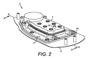
図1乃至6を参照すると、背景の情報のため蒸気装置1が示されている。蒸気装置1は、蒸気アイロン1の形をとる。蒸気アイロン1は、筐体2及び底板3を有する。 Referring to FIGS. 1-6, a steam device 1 is shown for background information. The steam device 1 takes the form of a steam iron 1. The steam iron 1 has a housing 2 and a bottom plate 3.
筐体2は、蒸気アイロン1の先端2Bとは遠位の筐体2の端部に配置された、ヒール部2Aを有する。使用されていないときには、蒸気アイロン1は、底板3がいずれの面にも接触しないように、ヒール部2Aの上に静置された、安定した非アイロンがけ直立位置に置かれることができる。
The housing 2 has a
底板3は、布処置プレート4及び蒸気生成プレート5を有する。布処置プレート4の主面は、使用の間に蒸気により処置されるべき布Fに当てられる、布処置面4Aを有する。蒸気生成プレート5は、布処置プレート4の布処置面4Aに平行であり、該布処置面とは反対の方向に面する、蒸気生成面5Aを有する。
The bottom plate 3 has a cloth treatment plate 4 and a steam generation plate 5. The main surface of the cloth treatment plate 4 has a
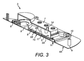
布処置プレート4は、複数の蒸気孔6を有する。蒸気孔6は、蒸気生成プレート5の周縁部の近くに、該周縁部とは離隔されて配置される。蒸気孔6の数は変更されても良いことは、理解されるであろう。1つの蒸気孔が存在しても良いし、複数の蒸気孔6が布処置面4Aに分散させられていても良い。
The cloth treatment plate 4 has a plurality of vapor holes 6. The steam hole 6 is disposed near the periphery of the steam generation plate 5 and spaced from the periphery. It will be appreciated that the number of steam holes 6 may be varied. One steam hole may be present, or a plurality of steam holes 6 may be dispersed on the
底板3はまた、カバー7を有する。カバー7は、蒸気生成プレート5に装着され、底板3の上端を定義する。蒸気生成プレート5とカバー7とは、一体的に形成されても良いことは、理解されるであろう。蒸気生成面5Aとカバー7との間に空間が定義され、該空間は、蒸気孔6と流体連通する蒸気室出口9を持つ蒸気室8を有する。
The bottom plate 3 also has a cover 7. The cover 7 is attached to the steam generation plate 5 and defines the upper end of the bottom plate 3. It will be understood that the steam generation plate 5 and the cover 7 may be integrally formed. A space is defined between the steam generating surface 5 </ b> A and the cover 7, and the space has a
加熱器10は、蒸気生成プレート5に部分的に受容され、蒸気生成プレート5の両側から突出する。加熱器10は、蒸気アイロン1のヒール部2Aから先端2Bへの方向に延在する、底板3の長軸A−Aと同じ方向において、蒸気生成プレート5に長手方向に沿って延在する。加熱器10は、加熱器10の先端が蒸気アイロン1のヒール部2Aから遠位に配置されるような、U字型の構成を持つ。加熱器10は、蒸気室8の周縁部の周りに部分的に延在し、動作させられたときに蒸気生成プレート5に熱を伝達させるよう構成される。加熱器10の構成は別のものであっても良いことは、理解されるであろう。
The
水供給ユニット11が、蒸気アイロン1の筐体2のなかに配置される。水供給ユニット11は、水タンク12、ポンプ13及び水入口14を有する。ポンプ13は、水タンク12から水入口14に液体の水を供給するよう構成される。水入口14は、供給された液体の水を、蒸気生成面5Aに噴霧、滴下又は噴射するよう構成され、これにより、液体の水が蒸気生成面5Aに広がるようにする。それ故、加熱器10が蒸気生成面5Aを加熱するよう動作させられると、蒸気生成面5A上の液体の水が、蒸気室8のなかで蒸気へと蒸発させられる。該蒸気は、蒸気室出口9から流れ出て、次いで蒸気孔6を通り布処置面4Aから放出される。それ故、布処置面4Aに当てられた布Fは、蒸気により処置される。
A
蒸気孔6から蒸気がけされるべき布Fに放出される蒸気の量は、水供給ユニット11により蒸気室8へと供給される液体の水の量を変化させることにより制御されることができる。より具体的には、蒸気生成面5Aに供給される液体の水の流量を調節し、蒸気室8において生成される蒸気の流量を制御するため、ポンプ13の速度がコントローラ(図示されていない)により変更されても良い。
The amount of steam released from the steam hole 6 to the cloth F to be steamed can be controlled by changing the amount of liquid water supplied to the
例えば、除去し難いしわを取り除くために、又は効果的なしわの除去のためには高い流量の蒸気を必要とする特定のタイプの布からしわを取り除くために、蒸気アイロン1が用いられる場合には、高い流量の蒸気が蒸気孔6から放出されるような態様で、蒸気アイロン1を動作させることが時々必要となる。高い流量の蒸気を生成するため、高い流量で液体の水を水タンク12から蒸気生成面5Aに供給するよう、水供給ユニット11が動作させられ、これにより蒸気室8において大量の蒸気が生成されるようにする。
For example, when the steam iron 1 is used to remove wrinkles that are difficult to remove, or to remove wrinkles from certain types of fabrics that require high flow steam for effective wrinkle removal. It is sometimes necessary to operate the steam iron 1 in such a way that a high flow rate of steam is discharged from the steam holes 6. In order to generate steam with a high flow rate, the
大量の蒸気を生成するため、液体の水が高い流量で蒸気生成面5Aに供給される場合には、該液体の水が蒸気室8に溜まり、蒸気室出口9から流れ出て、蒸気孔6から放出され得ることが分かっている。このことは、蒸気アイロン1からの熱水の「吐出」に帰着し得、ユーザに火傷させたり、蒸気により処置されている布Fにおいて染みを形成したりし得る。
In order to generate a large amount of vapor, when liquid water is supplied to the vapor generation surface 5A at a high flow rate, the liquid water accumulates in the
水供給ユニット11によって高い流量で液体の水が蒸気生成面5Aに供給される場合に、液体の水が蒸気室8に溜まることを防止するため、蒸気生成面5Aの表面積を増大させ、それにより、より多くの液体の水が蒸気生成面5Aと接触して、蒸気室8において液体の水が蒸発させられる速度を増大させることが知られている。それ故、蒸気室8における液体の水の蒸発速度が増大させられるため、液体の水が蒸気室8に溜まり続いて蒸気室出口9から蒸気孔6を通って流れ出ることが防止される。しかしながら、蒸気生成面5Aの表面積を増大させることは、蒸気アイロン1の重量を増大させ、筐体2のサイズを増大させ、蒸気アイロンが操作の難しいものとなり、保管も困難なものとなる。加えて、蒸気生成面5Aの表面積が増大させられると、蒸気室8を加熱するために、より大型の加熱器が必要となり、従って蒸気アイロン1が、使用の間に、より多くの電気エネルギーを消費することとなる。
In order to prevent liquid water from accumulating in the
蒸気アイロン1は、蒸気室出口9を蒸気孔6と流体連通させる、出口流部分15を有する。出口流部分15は、蒸気生成プレート5と布処置プレート4との間に配置され、流体が、入り組んだ又は間接的な経路で、蒸気室出口9から蒸気孔6へと流れるよう構成される。それ故、蒸気及び液体の水が直接的な直線状の経路を辿ることが可能である場合と比べて、蒸気及び液体の水が蒸気室8から蒸気孔6へと移動するのに要する時間が増大させられる。
The steam iron 1 has an
布処置プレート4は、布処置面4Aとは反対側を向き、出口流部分15の第1の境界面4Bを形成する、主面を有する。蒸気生成プレート5は、蒸気生成面5Aとは反対側を向き、出口流部分15の第2の境界面5Bを形成する、主面を有する。第1の境界面4Bと第2の境界面5Bとは、互いに平行であり互いに面している。
The cloth treatment plate 4 has a main surface that faces away from the cloth treatment surface 4 </ b> A and forms the first boundary surface 4 </ b> B of the
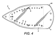
出口流部分15は、外側側壁16及び内側壁17を有する。内側壁17は、出口流部分15を通る流体の流れを方向付けるためのバッフルとして機能する。図5及び6においては14個の内側壁17が示されているが、内側壁17の数及び構成は、出口流部分15を通る所望の流路に依存して変更されても良いことは、理解されるであろう。
The
外側側壁16は、出口流部分15の最大の延長を定義し、蒸気室出口9からの流体が流れることが可能な室を形成する。外側側壁16は、出口流部分15を通る流体の流れを方向付けるバッフルとして機能する。外側側壁16の構成は、出口流部分15を通る所望の流路に応じて変更されても良いことは、理解されるであろう。
The
外側側壁16は、蒸気生成プレート5から延在し、第2の境界面5Bを部分的に囲む。内側壁17は、第2の境界面5Bから延在する。外側側壁16及び内側壁17は、蒸気生成プレート5と一体的に形成されるが、該構成は変更されても良いことは理解されるであろう。外側側壁16及び内側壁17は、蒸気生成プレート5から延在し、加熱器10から外側側壁16及び内側壁17への熱伝導を最大化することを支援する。このことは、外側側壁16及び内側壁17の温度を増大させることを支援し、それにより外側側壁16及び内側壁17に接触する液体の水が、より迅速に蒸気へと蒸発させられるようにする。
The
第1及び第2の境界面4B、5B並びに外側側壁16及び内側壁17は、出口流部分15の蒸気接触面を形成する。加熱器10は、外側側壁16の近くにおいて、出口流部分15の周縁部のまわりに部分的に延在し、これにより、加熱器10が動作させられているとき、蒸気室出口9から蒸気孔6への蒸気及び液体の水の経路が加熱される。
The first and second boundary surfaces 4B and 5B and the
蒸気は、蒸気室8から、蒸気室出口9を介して、出口流部分15へと流れる。外側側壁16は、蒸気室出口9からの流体の流れを、出口流部分15へと向ける。外側側壁16は、おおむねU字型であり、蒸気室出口9は、外側側壁16の先端の近くにある。
Steam flows from the
出口流部分15において定義される流路は、図6において矢印「B」により示され、入り組んだ又は間接的な流路である。即ち、流路Bに沿って流れる流体は、流路Bに沿って通過するときに、少なくとも1回は方向を変える必要がある。このことは、流路Bに沿って流れる流体の、1つ以上の外側側壁16及び内側壁17との衝突を引き起こすことを支援する。出口流部分15において定義される流路Bは、迷路状の構成を持つ。より具体的には、内側壁17は、出口流部分15において定義される流路Bが、蛇行する構成を持つように構成される。
The flow path defined in the
内側壁17は、第1の群17Aと第2の群17Bとに構成される。外側側壁16は、互いに面し、底板3の長軸A−Aの反対側に配置された、第1の面16A及び第2の面16Bを有する。
The
第1の群17Aの内側壁17は、外側側壁16の第1の面16Aから延在し、それぞれが、長軸A−Aに垂直な方向において、外側側壁16の第2の面16Bに向かって延在し、且つ該第2の面16Bからは離隔されている。第2の群17Bの内側壁17は、外側側壁16の第2の面16Bから延在し、それぞれが、長軸A−Aに垂直な方向において、外側側壁16の第1の面16Aに向かって延在し、且つ該第1の面16Aからは離隔されている。内側壁17は、互いに平行である。
The
第1の群17Aの内側壁17は、第2の群17Bの内側壁17により介挿され、第1及び第2の群17A、17Bの内側壁17が、底板3の長軸A−Aの方向においてシーケンシャルに交番するようにされる。第1及び第2の群17A、17Bの内側壁17は、底板3の長軸A−Aに垂直な方向に重畳し、それにより長軸A−Aの方向において出口流部分15を通る見通し線がないようにされる。斯くして、出口流部分15は、蒸気室出口9から蒸気孔6へと間接的な経路をとるチャネルを有する。
The
出口流部分15の流路Bは、蛇行する構成を有するため、蒸気室出口9からの流路Bに沿って流れる流体は、蒸気孔6へと流れる際に、方向を複数回変える必要がある。このことは、流路Bに沿って流れる流体の、外側側壁16及び内側壁17との複数回の衝突を引き起こすことを支援する。内側壁17はバッフルとして機能し、出口流部分15を通る流体の流れを方向付ける。
Since the flow path B of the
蒸気孔6は、外側側壁16の、蒸気室出口9とは反対側に配置され、これにより、蒸気室8を出る流体が、蒸気孔6に到達するためには、出口流部分15の迷路状構成を通る間接的な経路を流れる必要があるようにされる。蒸気室出口9を出る蒸気及び液体の水は、間接的な経路を流れる必要があるため、蒸気及び液体の水が直接的な直線状の経路を辿ることが可能である場合と比べて、蒸気及び液体の水が蒸気室出口9から蒸気孔6へと移動するのに要する時間が増大させられる。それ故、蒸気生成面5Aに供給された液体の水が蒸気室8に溜まり、蒸気室出口9から出口流部分15へと流れ出た場合、該液体の水は、該液体の水が蒸気孔6へと直接的な直線状の経路を辿ることが可能である場合と比べて、蒸気孔6に到達するために長い経路を辿る必要があることとなる。流路Bをより入り組んだものとすることは、液体の水が蒸気室出口9から蒸気孔6まで移動するのに要する時間を増大させることが分かっている。
The steam hole 6 is arranged on the side of the
加熱器10は、出口流部分15を加熱し、蒸気室8において蒸発させられず出口流部分15へと流入した液体の水が蒸気へと蒸発させられるようにし、それにより、液体の水が出口流部分15において溜まり、蒸気孔6から放出されることを防止する。それ故、同様のサイズの蒸気生成面5Aを持つが、蒸気室出口9と蒸気孔6との間に間接的な流路Bを含まない、従来の蒸気アイロンよりも、蒸発アイロン1は、より多くの蒸気を生成することが可能である。より具体的には、出口流部分15における液体の水が、より長い時間の間加熱器10からの熱にさらされることとなり、従って、液体の水が蒸気室出口9から蒸気孔6へと直接に流れることが可能である場合よりも、多くの液体の水が出口流部分15において蒸気へと蒸発させられる。斯くして、水供給ユニット11は、蒸気生成面5Aの表面積が増大させられる必要なく、高い流量で蒸気室8へと液体の水を供給し、多くの量の蒸気を生成するよう動作させられることができる。このことは、該液体の水が蒸気孔6への間接的な流路を辿る必要があり、従ってより長い時間の間加熱器10からの熱にさらされ、より多くの液体の水が蒸気へと蒸発させられるようになるという事実のため、液体の水が蒸気室出口9から流れ出る場合には、出口流部分15において蒸気へと蒸発させられるため、蒸気アイロン1の蒸気室8において液体の水が溜まることを防止する必要がないことによる。それ故、同様のサイズの蒸気生成面を持つが、蒸気室出口と蒸気孔との間に間接的な流路を含まない、既知の蒸気アイロンよりも、蒸気アイロン1は、高い流量の蒸気を生成するのに適している。
The
加えて、出口流部分15が加熱器10により加熱されるため、蒸気アイロン1の効率を低下させ得る、出口流部分15における蒸気が液体の水へと凝縮することが、防止される。
In addition, since the
出口流部分15の構成は、変更されても良い。出口流部分15は、流路Bに沿って流れる流体に対して、複数回の方向の変化を引き起こす。間接的な流体の流路Bを備えることにより、出口流部分15を通過する流体の流れの方向が逸らされる。流れの方向を逸らすことに対して、流体中の重い水滴が抵抗を持つため、出口流部分15の外側壁16及び内側壁17に対する作用が、小さな水滴として分散させられる。これら小さな水滴は、より容易に蒸発させられ得る。出口流部分15の外側壁16又は内側壁17の表面に接触する水滴は、外側壁16及び内側壁17に伝導される熱により蒸発させられ得る。
The configuration of the
出口流部分15は、出口流部分15における液体の水を吸収するための多孔質層を有する。より具体的には、衣類処置プレート4及び蒸気生成プレート5はそれぞれ、多孔質層(図示されていない)及び非多孔質層(図示されていない)を有する。衣類処置プレート4の非多孔質層は、布処置面4Aを有し、衣類処置プレート4の多孔質層は、第1の境界面4Bを有する。蒸気生成プレート5の非多孔質層は、蒸気生成面5Aを有し、蒸気生成プレート5の多孔質層は、第2の境界面5Bを有する。衣類処置プレート4及び蒸気生成プレート5の多孔質層は、出口流部分15における液体の水を吸収して、液体の水の流れを低速化し、それにより、蒸気室出口9から蒸気孔6まで出口流部分15を通り液体の水が移動するのに、より長い時間がかかるようにする。それ故、出口流部分15における液体の水は、より長い時間の間加熱器10からの熱にさらされることとなり、それ故、多孔質層が含まれない場合に比べて、多くの液体の水が蒸気へと蒸発させられる。更に、これら多孔質層は、第1及び第2の境界面4B、5Bの表面積を増大させ、従って加熱器10により加熱される第1及び第2の境界面4B、5Bから出口流部分15における液体の水への熱伝達を増大させる。
The
衣類処置プレート4及び蒸気生成プレート5の多孔質層の厚さを増大させることは、出口流部分15における液体の水が蒸気へと蒸発させられ得る速度を増大させることが分かっている。このことは、多孔質層の厚さを増大させることが、該多孔質層により吸収されることができる出口流部分15における液体の水の量を増大させ、また第1及び第2の境界面4B、5Bの表面積を増大させることによる。好適には、該多孔質層の厚さは0.2mmよりも小さく、該多孔質層の厚さは0.1mmである。しかしながら、該多孔質層の他の厚さも可能であることは、認識されるであろう。別の構成においては、これら多孔質層の一方又は両方が省略される。
Increasing the thickness of the porous layers of the garment treatment plate 4 and the vapor generating plate 5 has been found to increase the rate at which liquid water at the
出口流部分15の第1及び第2の境界面4B、5B並びに外側壁16及び内側壁17は、蒸気生成を促進する被覆(図示されていない)を有する。該被覆は例えば、LUDOX(登録商標)のようなコロイド状蒸気促進材である。該被覆は、第1及び第2の境界面4B、5Bに液体の水を広げさせ、それにより液体の水がより効率良く蒸気へと蒸発させられるようにする。これに加えて、又は代替として、該被覆は、加熱器10により液体の水が過度に早く加熱されることを防止し、それ故ライデンフロスト効果が軽減されるような断熱材として機能し、これがない場合には、蒸気の層が第1及び第2の境界面4B、5B間に形成され、液体の水が第1及び第2の境界面4B、5Bに直接に接触することを防止してしまい、斯くして蒸気への液体の水の効果的な蒸発を阻害してしまう。それ故、該被覆は、出口流部分15における液体の水の蒸気への蒸発速度を増大させるよう構成される。該被覆は多孔質であっても良く、布処置プレート4及び蒸気生成プレート5の多孔質層を形成しても良い。代替としては、該被覆はこれら多孔質層の表面に塗布されても良い。
The first and second interface surfaces 4B, 5B and the outer and
該被覆は、底板3の組み立てに先立ち、第1及び第2の境界面4B、5B並びに外側及び内側壁16、17に該被覆を噴射することによって塗布されても良い。代替としては、該被覆は、最初に底板3を組み立て、次いで該被覆を気化させて出口流部分15を通過させ、第1及び第2の境界面4B、5B並びに外側及び内側壁16、17の表面に該被覆が堆積させられるようにし、次いで該被覆を乾燥させることにより、塗布されても良い。
The coating may be applied by spraying the coating on the first and second interface surfaces 4B, 5B and the outer and
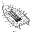
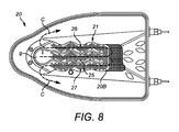
図7及び8を参照すると、本発明の一実施例による蒸気装置1の底板の蒸気生成プレート20が示されている。該蒸気装置は、図1乃至6に関連して以上に説明された蒸気アイロン1と同じ幾つかの特徴を持つ蒸気アイロン1の形をとり、斯かる特徴は同じ参照番号を持つ。相違点は、図1乃至6に関連して以上に説明された蒸気アイロン1の蒸気生成プレート5が省略され、代替の蒸気生成プレート20により置き換えられている点である。
Referring to FIGS. 7 and 8, there is shown a
蒸気生成プレート20は図7及び8に示され、底板の布処置面に平行であり且つ該布処置面と反対の方向に面する蒸気生成面(図示されていない)を有する。
The
出口流部分21は、布処置プレートと蒸気生成プレート20との間に配置される。出口流部分21は、蒸気室出口9を蒸気孔(図示されていない)と流体連通させ、蒸気室出口9から蒸気孔への間接的な経路を流体が流れるよう構成される。それ故、蒸気及び液体の水が直接的な直線状の経路を辿ることが可能である場合と比べて、蒸気室出口9から蒸気孔へと蒸気及び液体の水が流れるのに要する時間が増大させられる。
The
該衣類処置プレートは、該布処置面とは反対の方向に面し、出口流部分21の第1の境界面(図示されていない)を形成する、主面を有する。蒸気生成プレート20は、該蒸気生成面とは反対の方向に面し、出口流部分21の第2の境界面20Bを形成する、主面を有する。該第1の境界面と第2の境界面20Bとは、互いに平行であり対向している。
The garment treatment plate has a major surface that faces away from the fabric treatment surface and forms a first interface (not shown) of the
出口流部分21は、外側側壁22と、第1及び第2の内側壁23、24とを有する。第1及び第2の内側壁23、24は、出口流部分21を通る流体の流れを方向付けるためのバッフルとして機能する。第1及び第2の内側壁23、24の数及び構成は、出口流部分21を通る所望の流路に依存して変更されても良いことは、理解されるであろう。
The
外側側壁22は、出口流部分21の最大の広がりを定義し、蒸気室からの流体が蒸気孔へと流れることができる室を形成する。外側側壁22は、出口流部分21を通る流体の流れを方向付けるためのバッフルとして機能する。外側側壁22の構成は、出口流部分21を通る所望の流路に応じて変更されても良いことは、理解されるであろう。
The
外側側壁22は、蒸気生成プレート20から延在し、第2の境界面20Bを部分的に囲む。外側側壁22は、概してU字型であり、閉じた端部22Aと、蒸気孔と流体連通した開いた端部22Bとを持つ。外側側壁22は、互いに面し、外側側壁22の該閉じた端部22Aと開いた端部22Bとの間に延在する、第1及び第2の面22C、22Dを有する。外側側壁22並びに第1及び第2の内側壁23、24は、蒸気生成プレート20から延在し、該プレートと一体的に形成されるが、該構成は変更されても良いことは理解されるであろう。
The
第1及び第2の内側壁23、24は、蒸気室出口9の対向する側から延在し、底板の長軸A−Aの方向において外側側壁22の閉じた端部22Aに向かって延在し、且つ該閉じた端部22Aからは離隔されている。第1及び第2の内側壁23、24は、底板の長軸A−Aの反対側に配置される。
The first and second
第1及び第2の内側壁23、24間に、第1のチャネル25が形成される。第1の内側壁23と外側側壁22の第1の面22Cとの間に、第2のチャネル26が形成される。第2の内側壁24と外側側壁22の第2の面22Dとの間に、第3のチャネル27が形成される。第2及び第3のチャネル26、27は、底板の長軸A−Aの反対側に配置され、第1のチャネル25は、第2のチャネル26と第3のチャネル27との間に配置される。第1、第2及び第3のチャネル25、26、27はそれぞれ、おおむね底板の長軸A−Aと平行に延在する。
A
第1のチャネル25は、蒸気室出口9を外側側壁22の閉じた端部22Aと流体連通させる。第2及び第3のチャネル26、27はそれぞれ、外側側壁22の閉じた端部22A及び開いた端部22Bと流体連通する。外側側壁22の開いた端部22Bは、蒸気孔と流体連通する。蒸気室出口9は、蒸気室出口9を出る流体が、蒸気孔に到達する前に出口流部分21を通って流れる必要があるように構成される。それ故、蒸気室出口9を出た蒸気及び液体の水は、外側側壁22の閉じた端部22Aに向かって第1のチャネル25に沿って流れ、次いで方向を変えて、第2又は第3のチャネル26、27のいずれかを通って流れて、外側側壁22の開いた端部22Bに到達し、蒸気孔を通過する。斯くして、出口流部分21を流れる流体の経路は、流体が外側側壁22の閉じた端部22Aに到達したときに分かれ、第2又は第3のチャネル26、27のいずれかを通って流れる。
The
出口流部分21において定義される流路は、図8において矢印「C」により示され、入り組んだ又は間接的な流路である。即ち、第1及び第2の内側壁23、24が迷路状の構成を形成するため、流路Cに沿って流れる流体は、流路Cを通過するときに少なくとも1度は方向を変える必要がある。このことは、流路Cに沿って流れる流体の、外側側壁22及び第1及び第2の内側壁23、24のうち1つ以上との衝突を引き起こすことを支援する。
The flow path defined in the
蒸気室出口9から出る蒸気及び液体の水は、蒸気孔に到達するために間接的な経路を流れる必要があるため、蒸気及び液体の水が直接的な直線状の経路を辿ることが可能である場合と比べて、蒸気室出口9から蒸気孔へと蒸気及び液体の水が流れるのに要する時間が増大させられる。それ故、蒸気生成面に供給された液体の水が蒸気室に溜まり、蒸気室出口9から出口流部分21へと流れ出た場合、該液体の水は、該液体の水が蒸気孔へと直接的な直線状の経路を辿ることが可能である場合と比べて、蒸気孔に到達するために長い経路を辿る必要があることとなる。
Vapor and liquid water exiting the vapor chamber outlet 9 must flow through an indirect path to reach the vapor hole, so that the vapor and liquid water can follow a direct linear path. Compared to the case, the time required for the vapor and liquid water to flow from the vapor chamber outlet 9 to the vapor hole is increased. Therefore, when the liquid water supplied to the steam generation surface accumulates in the steam chamber and flows out from the steam chamber outlet 9 to the
第1及び第2の境界面20B、外側側壁22並びに第1及び第2の内側壁23、24は、出口流部分21の蒸気接触面を形成する。加熱器(図示されていない)は、出口流部分21の周囲を部分的に囲んで延在し、これにより、該加熱器が動作させられると流路Cが加熱される。該加熱器は、出口流部分21を加熱するように構成され、これにより、蒸気室において蒸発させられず続いて出口流部分21に流入した液体の水が蒸気へと蒸気させられ、これにより液体の水が出口流部分21に溜まり続いて蒸気孔から放出されることを防止する。
The first and second boundary surfaces 20 </ b> B, the
第1、第2及び第3のチャネル25、26、27はそれぞれ、出口流部分21において移動する流体の方向変化を引き起こす起伏した又は波状の経路に延在し、これにより比較的重い大きな水滴が、外側側壁22及び第1及び第2の内側壁23、24に当たるようにする。このことは、流路Cに沿って流れる流体の、出口流部分21の表面に対する複数回の衝突を引き起こし、蒸気から液体の水の大きな滴を取り除くことを支援する。
The first, second and
該蒸気アイロンは、同様のサイズの蒸気生成面を持つが、蒸気室出口9と蒸気孔との間に間接的な流路Cを含まない、従来の蒸気アイロンよりも、多くの蒸気を生成することが可能である。このことは、出口流部分21に流入する液体の水が、より長い時間の間加熱器からの熱にさらされ、従って、蒸気室出口9から蒸気孔へと液体の水が直接に流れることが可能である場合よりも、出口流部分21における多くの液体の水が蒸気へと蒸気させられることによる。斯くして、水供給ユニットは、蒸気生成プレート20のサイズが増大させられる必要なく、高い流量で液体の水を蒸気室へと供給するよう動作させられることができる。それ故、本発明の本実施例の蒸気アイロンは、同様のサイズの蒸気生成プレートを持つが、蒸気室出口と蒸気孔との間に間接的な流路を持たない、既知の蒸気アイロンよりも、高い流量の蒸気を生成するのに適している。加えて、出口流部分21が加熱器により加熱されるため、蒸気アイロンの効率を低下させ得る、出口流部分21における蒸気が液体の水へと凝縮することが防止される。
The steam iron has a similar size steam generating surface, but generates more steam than a conventional steam iron that does not include an indirect flow path C between the steam chamber outlet 9 and the steam hole. It is possible. This means that the liquid water flowing into the
図1乃至6に関連して以上に説明された蒸気アイロン1の出口流部分15と同様に、図7及び8に示された実施例の出口流部分21は、出口流部分21における液体の水を吸収するための多孔質層を有する。より具体的には、衣類処置プレート及び/又は蒸気生成プレート20が、出口流部分21における液体の水を吸収して、液体の水の流れを低速化し、それにより、蒸気室出口9から蒸気孔まで出口流部分21を通り液体の水が移動するのに、より長い時間がかかるようにするよう構成された、多孔質層を有する。それ故、出口流部分21における液体の水は、より長い時間の間加熱器からの熱にさらされることとなり、それ故、多孔質層が含まれない場合に比べて、多くの液体の水が蒸気へと蒸発させられる。更に、これら多孔質層は、第1及び第2の境界面20Bの表面積を増大させ、従って加熱器により加熱される第1及び第2の境界面20Bから出口流部分21における液体の水への熱伝達を増大させる。代替の実施例においては、出口流部分21は多孔質を有さない。
Similar to the
出口流部分21は、複数の構造28を有する。該複数の構造28は、第1及び第2の境界面20Bにおける複数の凹部28A、及び第1及び第2の境界面20Bから延在する複数の突出部28Bの形をとる。出口流部分21における液体の水は凹部28Aに流入し、これにより出口流部分21を通る液体の水の流速が低下させられ、そのため出口流部分21における、より多くの液体の水が、蒸気孔に到達する前に蒸気へと蒸発させられるようになる。加えて、凹部28Aは、第1及び第2の境界面20Bの表面積を増大させ、それ故第1及び第2の境界面20Bと液体の水との間の熱伝達を増大させ、それにより液体の水の蒸発速度が増大させられる。更に、出口流部分21における液体の水は、突出部28Bのまわりを流れ、これにより該液体の水の流速が低下させられ、それによりそのため出口流部分21における、より多くの液体の水が、蒸気孔に到達する前に蒸気へと蒸発させられるようになる。加えて、突出部28Bは、第1及び第2の境界面20Bの表面積を増大させ、それ故第1及び第2の境界面20Bと液体の水との間の熱伝達が増大させられる。代替の実施例(図示されていない)においては、第1及び第2の境界面20Bの一方における凹部28A、及び/又は第1及び第2の境界面20Bの一方又は両方における突出部28Bが、省略される。図1乃至6に関連して以上に説明された蒸気アイロン1の出口流部分15もまた、出口流部分15にける液体の水の蒸発速度を増大させるための複数の構造を有しても良いことは、認識されるべきである。
The
図1乃至6に関連して以上に説明された蒸気アイロン1の出口流部分15と同様に、図7及び8に示された実施例の出口流部分21は、蒸気生成を促進する被覆(図示されていない)を有する。より具体的には、第1及び第2の境界面20B、外側側壁22並びに出口流部分21の第1及び第2の内側壁23、24のうち1つ以上が、蒸気生成を促進する被覆(図示されていない)を有する。該被覆は蒸気促進材であり、例えばLUDOX(登録商標)のようなコロイド状蒸気促進材であっても良い。該被覆は、第1及び第2の境界面20Bに液体の水を広げさせ、それにより液体の水がより効率良く蒸気へと蒸発させられるようにする。これに加えて、又は代替として、該被覆は、加熱器により液体の水が過度に早く加熱されることを防止し、それ故ライデンフロスト効果を軽減する。それ故、該被覆は、出口流部分21における液体の水の蒸気への蒸発速度を増大させるよう構成される。
Similar to the
以上に説明された実施例においては、出口流部分15、21における液体の水が、第1の境界面4B及び第2の境界面5B、20Bの両方と接触することを促進するため、第1の境界面4Bと第2の境界面5B、20Bとの間の距離である、出口流部分15、21の高さH(図6に示される)は、5mm以下であり、好適には3mm以下である。このことは、出口流部分15、21における液体の水が、第1の境界面4B及び第2の境界面5B、20Bの両方により同時に加熱されるようにし、液体の水が蒸気へと蒸発させられる速度を増大させる。以上に説明された実施例においては、出口流部分15、21の高さHは3mmである。
In the embodiment described above, the liquid water in the
以上に説明された実施例においては、被覆はLUDOX(登録商標)を有するが、代替の実施例においては、該被覆はケイ酸塩、リン酸塩、ホウ酸塩又はXYLAN(登録商標)のような他の成分を有しても良い。 In the embodiments described above, the coating has LUDOX®, but in alternative embodiments the coating is like silicate, phosphate, borate or XYLAN®. Other components may be included.
以上に説明された実施例においては、蒸気装置1は蒸気アイロン1の形をとる。しかしながら、本発明は他のタイプの蒸気装置との使用にも適していることは、認識されるべきである。例えば、代替の一実施例(図示されていない)においては、蒸気装置は、垂直に吊るされた布からしわを取り除くのに適した布用スチーマのためのスチーマヘッドの形をとる。 In the embodiment described above, the steam device 1 takes the form of a steam iron 1. However, it should be appreciated that the present invention is suitable for use with other types of steam equipment. For example, in an alternative embodiment (not shown), the steam device takes the form of a steamer head for a fabric steamer suitable for removing wrinkles from a vertically suspended fabric.
以上に説明された実施例においては、水タンク12は、蒸気アイロン1の筐体2内に配置される。しかしながら、代替の一実施例(図示されていない)においては、水タンク12は、別個のスタンド又は基部ユニットに配置され、該基部ユニットからホースを介して蒸気生成面4Aへと液体の水が供給される。ポンプ13は、蒸気アイロン1の筐体2に配置されても良いし、又は基部ユニットに配置されても良い。
In the embodiment described above, the
「有する(comprising)」なる語は他の要素又はステップを除外するものではなく、「1つの(a又はan)」なる不定冠詞は複数を除外するものではないことは、理解されるであろう。単一のプロセッサが、請求項に列記された幾つかのアイテムの機能を実行しても良い。特定の手段が相互に異なる従属請求項に列挙されているという単なる事実は、これら手段の組み合わせが有利に利用されることができないことを示すものではない。請求項におけるいずれの参照記号も、請求の範囲を限定するものとして解釈されるべきではない。 It will be understood that the word “comprising” does not exclude other elements or steps, and the indefinite article “a” or “an” does not exclude a plurality. . A single processor may perform the functions of several items recited in the claims. The mere fact that certain measures are recited in mutually different dependent claims does not indicate that a combination of these measured cannot be used to advantage. Any reference signs in the claims should not be construed as limiting the claim.
本出願において請求項は特徴の特定の組み合わせに向けたものであるが、本発明の開示の範囲は、いずれかの請求項において現在請求されているものと同一の発明に関するものであろうとなかろうと、また本発明が軽減するものと同一の技術的課題のいずれか又は全てを軽減するものであろうとなかろうと、明示的若しくは暗黙的にここで開示されたいずれの新規な特徴若しくは特徴の新規な組み合わせ、又はその一般化をも含むことは、理解されるべきである。本出願人はここで、本出願又は本出願から導かれるいずれかの更なる出願の手続きの間に、斯かる特徴及び/又は斯かる特徴の組み合わせに対して、新たな請求項が作成され得ることを注記しておく。 In this application, the claims are directed to a particular combination of features, but the scope of the disclosure of this invention may or may not be related to the same invention as currently claimed in any claim. And any novel features or features disclosed herein, either explicitly or implicitly, whether or not alleviating any or all of the same technical problems as the invention alleviates. It should be understood that combinations, or generalizations thereof, are also included. The applicant may now create new claims for such features and / or combinations of such features during the procedure of this application or any further application derived from this application. Note that.
Claims (14)
布処置面及び蒸気がけされるべき布へと蒸気が放出されるときに通る少なくとも1つの蒸気孔を有する、布処置プレートと、
前記蒸気生成面と前記布処置面との間に配置され、前記蒸気室と前記少なくとも1つの蒸気孔との間の間接的な流路を定義する、出口流部分と、
前記蒸気室から前記出口流部分に入る液体の水が蒸気へと蒸発させられるよう、前記出口流部分を加熱するための、加熱器と、
を有する蒸気装置において、前記出口流部分は、前記出口流部分を通って流れる液体の水の流量を低減させるための複数の凹部を備えた、少なくとも1つの境界面を有することを特徴とする、蒸気装置。 A vapor chamber having a vapor generating surface through which liquid is supplied and vaporized into vapor;
A cloth treatment plate having at least one vapor hole through which the vapor treatment surface and vapor are released to the cloth to be vaporized;
An outlet flow portion disposed between the steam generating surface and the fabric treatment surface and defining an indirect flow path between the steam chamber and the at least one steam hole;
A heater for heating the outlet flow portion such that liquid water entering the outlet flow portion from the vapor chamber is evaporated into steam;
Wherein the outlet flow portion has at least one interface with a plurality of recesses for reducing the flow rate of liquid water flowing through the outlet flow portion. Steam equipment.
Applications Claiming Priority (3)
| Application Number | Priority Date | Filing Date | Title |
|---|---|---|---|
| EP14185071 | 2014-09-17 | ||
| EP14185071.9 | 2014-09-17 | ||
| PCT/EP2015/070549 WO2016041820A1 (en) | 2014-09-17 | 2015-09-09 | A steam device |
Publications (2)
| Publication Number | Publication Date |
|---|---|
| JP2017528221A true JP2017528221A (en) | 2017-09-28 |
| JP2017528221A5 JP2017528221A5 (en) | 2019-01-31 |
Family
ID=51570305
Family Applications (1)
| Application Number | Title | Priority Date | Filing Date |
|---|---|---|---|
| JP2017512945A Ceased JP2017528221A (en) | 2014-09-17 | 2015-09-09 | Steam equipment |
Country Status (6)
| Country | Link |
|---|---|
| US (1) | US10287725B2 (en) |
| EP (1) | EP3194648B1 (en) |
| JP (1) | JP2017528221A (en) |
| CN (1) | CN107075783B (en) |
| RU (1) | RU2689078C2 (en) |
| WO (1) | WO2016041820A1 (en) |
Cited By (1)
| Publication number | Priority date | Publication date | Assignee | Title |
|---|---|---|---|---|
| JP2021180865A (en) * | 2018-11-19 | 2021-11-25 | アイリスオーヤマ株式会社 | Clothing steamer |
Families Citing this family (11)
| Publication number | Priority date | Publication date | Assignee | Title |
|---|---|---|---|---|
| CN108560222B (en) * | 2018-06-21 | 2023-09-08 | 广东美的环境电器制造有限公司 | Ironing apparatus |
| CN109519908B (en) * | 2018-12-18 | 2021-03-19 | 佛山市顺德区美的洗涤电器制造有限公司 | Steam generator and household appliance |
| EP3754096A1 (en) * | 2019-06-17 | 2020-12-23 | Koninklijke Philips N.V. | Portable textile treatment device with image sensor and thermal insulation means |
| EP3771769A1 (en) * | 2019-07-30 | 2021-02-03 | Koninklijke Philips N.V. | Steam generator with steam chamber and dosing hole arranged at proximity of a rear portion of the steam chamber |
| USD930925S1 (en) | 2020-03-04 | 2021-09-14 | Conair Corporation | Garment steamer |
| US11261561B2 (en) | 2020-03-04 | 2022-03-01 | Conair Llc | Garment steaming device |
| US11306429B2 (en) | 2020-03-04 | 2022-04-19 | Conair Llc | Garment steaming device |
| US11505893B2 (en) | 2020-03-04 | 2022-11-22 | Conair Llc | Garment steaming device |
| US11629453B2 (en) | 2020-03-04 | 2023-04-18 | Conair Llc | Garment steaming device |
| US12252839B2 (en) * | 2023-06-25 | 2025-03-18 | Shen Zhen Rone Phoenix Nest Design Development Co ., Ltd | Heating component and an ironing head |
| WO2026041610A1 (en) * | 2024-08-19 | 2026-02-26 | Versuni Holding B.V. | Garment steamer with improved steaming performances and functionalities |
Citations (5)
| Publication number | Priority date | Publication date | Assignee | Title |
|---|---|---|---|---|
| US2499184A (en) * | 1946-09-11 | 1950-02-28 | Gen Electric | Steam generating electric pressing iron |
| US2637126A (en) * | 1951-03-28 | 1953-05-05 | Hoover Co | Electric iron |
| JPH0339199A (en) * | 1989-07-05 | 1991-02-20 | Matsushita Electric Ind Co Ltd | Steam injector |
| JP2011509695A (en) * | 2007-10-05 | 2011-03-31 | コーニンクレッカ フィリップス エレクトロニクス エヌ ヴィ | Steam generator with hydrophilic coating |
| WO2014106793A1 (en) * | 2013-01-02 | 2014-07-10 | Koninklijke Philips N.V. | A garment steaming device |
Family Cites Families (15)
| Publication number | Priority date | Publication date | Assignee | Title |
|---|---|---|---|---|
| US1969583A (en) | 1933-03-01 | 1934-08-07 | Skolnik Max | Electric ironer and dampener |
| US2652645A (en) * | 1949-11-05 | 1953-09-22 | Casco Products Corp | Steam flatiron |
| US2744342A (en) * | 1952-04-19 | 1956-05-08 | Birtman Electric Co | Steam iron |
| US3110975A (en) * | 1960-11-30 | 1963-11-19 | Landers Frary & Clark | Steam iron with dual heating means |
| US3103079A (en) * | 1962-03-20 | 1963-09-10 | Westinghouse Electric Corp | Steam iron |
| US3811208A (en) * | 1972-11-07 | 1974-05-21 | Sunbeam Corp | Electric steaming and pressing appliance |
| CA1030055A (en) * | 1973-12-13 | 1978-04-25 | William E. Davidson | Steam iron |
| CN2530971Y (en) * | 2001-12-31 | 2003-01-15 | 广东德豪润达电气股份有限公司 | Low-temp. steam electric iron |
| JP2006526517A (en) * | 2003-04-25 | 2006-11-24 | コーニンクレッカ フィリップス エレクトロニクス エヌ ヴィ | Coating for steam generator |
| EP1756349A1 (en) * | 2004-06-02 | 2007-02-28 | Koninklijke Philips Electronics N.V. | Steam generator having at least one spiral-shaped steam channel and at least one flat resistive heating element |
| CN100523362C (en) * | 2005-01-31 | 2009-08-05 | 厦门灿坤实业股份有限公司 | Electric iron capable of quickly reducing temperature |
| FR2891846B1 (en) * | 2005-10-06 | 2007-12-14 | Rowenta Werke Gmbh Ges Mit Bes | IRON COMPRISING AN INSOLE COMPRISING A PARTICULAR STEAM OUTPUT HOLES NETWORK |
| CN201016147Y (en) | 2007-01-24 | 2008-02-06 | 程进村 | steam iron |
| FR2917429B3 (en) | 2007-06-15 | 2009-05-08 | Tsen Samson | STEAM IRON |
| CN103820987B (en) | 2014-02-26 | 2016-03-02 | 佛山市顺德区柏可斯电器科技有限公司 | A kind of burner cap of hanged ironing machine |
-
2015
- 2015-09-09 CN CN201580050124.3A patent/CN107075783B/en active Active
- 2015-09-09 EP EP15762561.7A patent/EP3194648B1/en active Active
- 2015-09-09 WO PCT/EP2015/070549 patent/WO2016041820A1/en not_active Ceased
- 2015-09-09 RU RU2017112987A patent/RU2689078C2/en not_active IP Right Cessation
- 2015-09-09 JP JP2017512945A patent/JP2017528221A/en not_active Ceased
- 2015-09-09 US US15/511,283 patent/US10287725B2/en not_active Expired - Fee Related
Patent Citations (5)
| Publication number | Priority date | Publication date | Assignee | Title |
|---|---|---|---|---|
| US2499184A (en) * | 1946-09-11 | 1950-02-28 | Gen Electric | Steam generating electric pressing iron |
| US2637126A (en) * | 1951-03-28 | 1953-05-05 | Hoover Co | Electric iron |
| JPH0339199A (en) * | 1989-07-05 | 1991-02-20 | Matsushita Electric Ind Co Ltd | Steam injector |
| JP2011509695A (en) * | 2007-10-05 | 2011-03-31 | コーニンクレッカ フィリップス エレクトロニクス エヌ ヴィ | Steam generator with hydrophilic coating |
| WO2014106793A1 (en) * | 2013-01-02 | 2014-07-10 | Koninklijke Philips N.V. | A garment steaming device |
Cited By (2)
| Publication number | Priority date | Publication date | Assignee | Title |
|---|---|---|---|---|
| JP2021180865A (en) * | 2018-11-19 | 2021-11-25 | アイリスオーヤマ株式会社 | Clothing steamer |
| JP7170350B2 (en) | 2018-11-19 | 2022-11-14 | アイリスオーヤマ株式会社 | clothing steamer |
Also Published As
| Publication number | Publication date |
|---|---|
| EP3194648B1 (en) | 2019-03-20 |
| CN107075783B (en) | 2019-11-08 |
| RU2689078C2 (en) | 2019-05-23 |
| US10287725B2 (en) | 2019-05-14 |
| WO2016041820A1 (en) | 2016-03-24 |
| EP3194648A1 (en) | 2017-07-26 |
| RU2017112987A3 (en) | 2018-11-27 |
| CN107075783A (en) | 2017-08-18 |
| RU2017112987A (en) | 2018-10-17 |
| US20170260684A1 (en) | 2017-09-14 |
Similar Documents
| Publication | Publication Date | Title |
|---|---|---|
| JP2017528221A (en) | Steam equipment | |
| JP2017528221A5 (en) | ||
| JP6617892B2 (en) | Washing machine having steam washing function and control method | |
| JP4469787B2 (en) | Electric iron | |
| US10240278B2 (en) | Steam iron head | |
| RU2650059C1 (en) | Steam head of iron | |
| RU2605845C2 (en) | Steam iron | |
| RU2677596C2 (en) | Steaming device component | |
| JP2017516538A (en) | Steamer Head | |
| RU2689064C2 (en) | Working part of steam iron | |
| US9664378B2 (en) | Energy efficient pressure less steam generator | |
| WO2020094293A1 (en) | A cooking device comprising a steam generator | |
| JP4923258B2 (en) | Superheated steam generator and superheated steam generation method | |
| JP6290196B2 (en) | Steam iron with steam permeable screen | |
| CN103541201B (en) | Garment Steamer Machine heating shower nozzle | |
| WO2017059710A1 (en) | Electric iron | |
| RU2694805C2 (en) | Steam ironing device comprising iron having sole, above which there is housing, equipped with heating element | |
| RU2761012C2 (en) | Device for steaming food and method for generating steam in it | |
| CN118773896A (en) | Clothes processing equipment | |
| JP2015025593A (en) | Superheated steam generating device and superheated steam generating method | |
| KR20090007119U (en) | Heat pipe | |
| JP2009133569A (en) | Liquid temperature riser | |
| JP2014150813A (en) | Clothes treatment apparatus |
Legal Events
| Date | Code | Title | Description |
|---|---|---|---|
| A521 | Request for written amendment filed |
Free format text: JAPANESE INTERMEDIATE CODE: A523 Effective date: 20180824 |
|
| A621 | Written request for application examination |
Free format text: JAPANESE INTERMEDIATE CODE: A621 Effective date: 20180824 |
|
| A521 | Request for written amendment filed |
Free format text: JAPANESE INTERMEDIATE CODE: A523 Effective date: 20181217 |
|
| A871 | Explanation of circumstances concerning accelerated examination |
Free format text: JAPANESE INTERMEDIATE CODE: A871 Effective date: 20181217 |
|
| A975 | Report on accelerated examination |
Free format text: JAPANESE INTERMEDIATE CODE: A971005 Effective date: 20190206 |
|
| A131 | Notification of reasons for refusal |
Free format text: JAPANESE INTERMEDIATE CODE: A131 Effective date: 20190212 |
|
| A521 | Request for written amendment filed |
Free format text: JAPANESE INTERMEDIATE CODE: A523 Effective date: 20190419 |
|
| A01 | Written decision to grant a patent or to grant a registration (utility model) |
Free format text: JAPANESE INTERMEDIATE CODE: A01 Effective date: 20190711 |
|
| A045 | Written measure of dismissal of application [lapsed due to lack of payment] |
Free format text: JAPANESE INTERMEDIATE CODE: A045 Effective date: 20191121 |