JP2017527742A - Energy extraction apparatus and method - Google Patents
Energy extraction apparatus and method Download PDFInfo
- Publication number
- JP2017527742A JP2017527742A JP2017521066A JP2017521066A JP2017527742A JP 2017527742 A JP2017527742 A JP 2017527742A JP 2017521066 A JP2017521066 A JP 2017521066A JP 2017521066 A JP2017521066 A JP 2017521066A JP 2017527742 A JP2017527742 A JP 2017527742A
- Authority
- JP
- Japan
- Prior art keywords
- fluid
- turbine
- disks
- energy
- moving
- Prior art date
- Legal status (The legal status is an assumption and is not a legal conclusion. Google has not performed a legal analysis and makes no representation as to the accuracy of the status listed.)
- Pending
Links
Images


Classifications
-
- F—MECHANICAL ENGINEERING; LIGHTING; HEATING; WEAPONS; BLASTING
- F24—HEATING; RANGES; VENTILATING
- F24F—AIR-CONDITIONING; AIR-HUMIDIFICATION; VENTILATION; USE OF AIR CURRENTS FOR SCREENING
- F24F12/00—Use of energy recovery systems in air conditioning, ventilation or screening
-
- F—MECHANICAL ENGINEERING; LIGHTING; HEATING; WEAPONS; BLASTING
- F01—MACHINES OR ENGINES IN GENERAL; ENGINE PLANTS IN GENERAL; STEAM ENGINES
- F01D—NON-POSITIVE DISPLACEMENT MACHINES OR ENGINES, e.g. STEAM TURBINES
- F01D1/00—Non-positive-displacement machines or engines, e.g. steam turbines
- F01D1/34—Non-positive-displacement machines or engines, e.g. steam turbines characterised by non-bladed rotor, e.g. with drilled holes
- F01D1/36—Non-positive-displacement machines or engines, e.g. steam turbines characterised by non-bladed rotor, e.g. with drilled holes using fluid friction
-
- F—MECHANICAL ENGINEERING; LIGHTING; HEATING; WEAPONS; BLASTING
- F01—MACHINES OR ENGINES IN GENERAL; ENGINE PLANTS IN GENERAL; STEAM ENGINES
- F01D—NON-POSITIVE DISPLACEMENT MACHINES OR ENGINES, e.g. STEAM TURBINES
- F01D15/00—Adaptations of machines or engines for special use; Combinations of engines with devices driven thereby
- F01D15/10—Adaptations for driving, or combinations with, electric generators
-
- F—MECHANICAL ENGINEERING; LIGHTING; HEATING; WEAPONS; BLASTING
- F01—MACHINES OR ENGINES IN GENERAL; ENGINE PLANTS IN GENERAL; STEAM ENGINES
- F01D—NON-POSITIVE DISPLACEMENT MACHINES OR ENGINES, e.g. STEAM TURBINES
- F01D25/00—Component parts, details, or accessories, not provided for in, or of interest apart from, other groups
- F01D25/24—Casings; Casing parts, e.g. diaphragms, casing fastenings
-
- H—ELECTRICITY
- H02—GENERATION; CONVERSION OR DISTRIBUTION OF ELECTRIC POWER
- H02K—DYNAMO-ELECTRIC MACHINES
- H02K7/00—Arrangements for handling mechanical energy structurally associated with dynamo-electric machines, e.g. structural association with mechanical driving motors or auxiliary dynamo-electric machines
- H02K7/18—Structural association of electric generators with mechanical driving motors, e.g. with turbines
- H02K7/1807—Rotary generators
- H02K7/1823—Rotary generators structurally associated with turbines or similar engines
-
- F—MECHANICAL ENGINEERING; LIGHTING; HEATING; WEAPONS; BLASTING
- F05—INDEXING SCHEMES RELATING TO ENGINES OR PUMPS IN VARIOUS SUBCLASSES OF CLASSES F01-F04
- F05D—INDEXING SCHEME FOR ASPECTS RELATING TO NON-POSITIVE-DISPLACEMENT MACHINES OR ENGINES, GAS-TURBINES OR JET-PROPULSION PLANTS
- F05D2220/00—Application
- F05D2220/60—Application making use of surplus or waste energy
- F05D2220/62—Application making use of surplus or waste energy with energy recovery turbines
-
- F—MECHANICAL ENGINEERING; LIGHTING; HEATING; WEAPONS; BLASTING
- F05—INDEXING SCHEMES RELATING TO ENGINES OR PUMPS IN VARIOUS SUBCLASSES OF CLASSES F01-F04
- F05D—INDEXING SCHEME FOR ASPECTS RELATING TO NON-POSITIVE-DISPLACEMENT MACHINES OR ENGINES, GAS-TURBINES OR JET-PROPULSION PLANTS
- F05D2220/00—Application
- F05D2220/70—Application in combination with
- F05D2220/76—Application in combination with an electrical generator
-
- Y—GENERAL TAGGING OF NEW TECHNOLOGICAL DEVELOPMENTS; GENERAL TAGGING OF CROSS-SECTIONAL TECHNOLOGIES SPANNING OVER SEVERAL SECTIONS OF THE IPC; TECHNICAL SUBJECTS COVERED BY FORMER USPC CROSS-REFERENCE ART COLLECTIONS [XRACs] AND DIGESTS
- Y02—TECHNOLOGIES OR APPLICATIONS FOR MITIGATION OR ADAPTATION AGAINST CLIMATE CHANGE
- Y02E—REDUCTION OF GREENHOUSE GAS [GHG] EMISSIONS, RELATED TO ENERGY GENERATION, TRANSMISSION OR DISTRIBUTION
- Y02E10/00—Energy generation through renewable energy sources
- Y02E10/20—Hydro energy
-
- Y—GENERAL TAGGING OF NEW TECHNOLOGICAL DEVELOPMENTS; GENERAL TAGGING OF CROSS-SECTIONAL TECHNOLOGIES SPANNING OVER SEVERAL SECTIONS OF THE IPC; TECHNICAL SUBJECTS COVERED BY FORMER USPC CROSS-REFERENCE ART COLLECTIONS [XRACs] AND DIGESTS
- Y02—TECHNOLOGIES OR APPLICATIONS FOR MITIGATION OR ADAPTATION AGAINST CLIMATE CHANGE
- Y02T—CLIMATE CHANGE MITIGATION TECHNOLOGIES RELATED TO TRANSPORTATION
- Y02T50/00—Aeronautics or air transport
- Y02T50/60—Efficient propulsion technologies, e.g. for aircraft
Abstract
【解決手段】 流体循環システムのインデックスラン以外の経路位置に設置され、導管中の移動する流体内のエネルギーを収穫するエネルギー抽出システムであって、このエネルギー抽出システムは、ハウジングと複数のディスクとを含み、前記移動する流体から運動エネルギーを収穫する少なくとも1つのタービンアセンブリと、前記複数のディスクを駆動するために、前記流体導管から前記移動する流体を受け取って前記タービンハウジング内に方向付ける入口と、前記移動する流体を前記タービンハウジングから前記流体導管に戻す出口とを含む。前記複数のディスクには出口開口部を含めることができ、この出口開口部は、移動する作動流体とディスクの接触部のらせん状経路の長さを最大限に伸ばす。【選択図】 図1An energy extraction system installed at a path position other than an index run of a fluid circulation system and harvesting energy in a moving fluid in a conduit, the energy extraction system comprising a housing and a plurality of disks. Including at least one turbine assembly for harvesting kinetic energy from the moving fluid; and an inlet for receiving and directing the moving fluid from the fluid conduit into the turbine housing to drive the plurality of disks; And an outlet for returning the moving fluid from the turbine housing to the fluid conduit. The plurality of disks may include an outlet opening, which maximizes the length of the helical path of the moving working fluid and disk contact. [Selection] Figure 1
Description
本願は、2014年6月24日付で出願された米国仮特許出願第62/016,162号「Energy Extraction Apparatus and Methods」(エネルギー抽出装置および方法)の優先権および利益を主張するものであり、この参照によりその全体が本明細書に組み込まれる。 This application claims priority and benefit of US Provisional Patent Application No. 62 / 016,162 “Energy Extraction Apparatus and Methods” filed on June 24, 2014, This reference is incorporated herein in its entirety.
本開示は、一般に冷暖房空調(heating, ventilation, and air conditioning:HVAC)を循環する流体、水、天然ガス、あるいは同様な建築物システムまたは他の任意の配管システムから運動エネルギーを抽出するよう構成された装置に関する。 The present disclosure is generally configured to extract kinetic energy from a fluid, water, natural gas, or similar building system or any other piping system that circulates in heating, ventilating, and air conditioning (HVAC). Related to the device.
冷暖房空調(heating, ventilation, and air conditioning:HVAC)システムは、当該空間全体にわたり配置構成された熱交換器に、加熱または冷却した作動流体を循環させることにより、閉鎖環境の温度を調節する。通常、ファンが熱交換器を通じて空気を循環させによることにより、加熱・冷却され、または乾燥した空気が生じる。HVACシステムの基本概念は、閉鎖空間と外部環境との間で熱エネルギーを移動させて、前記閉鎖空間内の状態を制御するというものである。HVACシステムに必要なこの熱移動機能を達成するには多数の装置が利用できる。端末ユニット、熱交換器、チラー(冷却器)、エアハンドリングユニット(air handling units:AHU)、専用外気システム(dedicated outdoor air system:DOAS)、強制通風ボイラー、ユニットヒーター(ユニット加熱器)、ファンコイルユニット(fan coil units:FCU)、およびダクトファーネス(ダクトヒーター)は、所与のHVACシステムに熱気または冷気を供給する装置のいくつかの例である。閉鎖空間の温度および湿度の制御に利用される特定の装置に関係なく、ACまたはDCを受電するモーターは、従来、1若しくはそれ以上のファンを駆動することにより、HVACシステムおよび/または熱交換器を流通する空気を動かす。 A heating, ventilating, and air conditioning (HVAC) system regulates the temperature of a closed environment by circulating a heated or cooled working fluid through a heat exchanger arranged throughout the space. Typically, a fan circulates air through a heat exchanger to produce heated or cooled or dry air. The basic concept of the HVAC system is to control the state in the enclosed space by transferring thermal energy between the enclosed space and the external environment. A number of devices are available to achieve this heat transfer function required for HVAC systems. Terminal unit, heat exchanger, chiller (cooler), air handling unit (AHU), dedicated outdoor air system (DOAS), forced draft boiler, unit heater (unit heater), fan coil Units (fan coil units: FCU) and duct furnaces (duct heaters) are some examples of devices that supply hot or cold air to a given HVAC system. Regardless of the specific equipment used to control the temperature and humidity of the enclosed space, motors that receive AC or DC have traditionally been driven by one or more fans to provide HVAC systems and / or heat exchangers. Move the air flowing through.
HVACシステムは運転および維持管理が高価で、そのコストは施設の運営費の大部分を占める。ACまたはDCモーターを利用してHVACシステム内の空気を動かすことは、加熱または冷却出力をエネルギー消費量と比較するためのエネルギー効率の指標である性能係数に悪影響を及ぼす。さらに、HVACシステムの操作に必要な複雑な電気配線および電気インフラストラクチャは、熟練した人材および頻繁な維持保全を必要とする。 The HVAC system is expensive to operate and maintain, and its cost accounts for the majority of the facility operating costs. Using an AC or DC motor to move air in the HVAC system adversely affects the performance factor, which is an indicator of energy efficiency for comparing heating or cooling output to energy consumption. In addition, the complex electrical wiring and electrical infrastructure required to operate the HVAC system requires skilled personnel and frequent maintenance.
ほとんどの建築物は、住居用、商業用、産業用、公共施設用、医療用のいずれであっても、飲用(家庭用)水の循環システムと、少なくとも1つのHVACシステムと、可能性として付加的な暖房システムとを有する。本明細書に記載しない他の流体循環システムも、本明細書に開示するエネルギーハーベスティングの概念および実施形態に関連する。建築物内におけるこれらのシステムの存在により、流体ですでに利用可能な運動エネルギーを収穫(ハーベスト)する機会をもたらす。 Most buildings, whether residential, commercial, industrial, public facilities, or medical, have the possibility of adding a drinking (household) water circulation system and at least one HVAC system And a typical heating system. Other fluid circulation systems not described herein are also relevant to the energy harvesting concepts and embodiments disclosed herein. The presence of these systems in the building provides an opportunity to harvest the kinetic energy already available in the fluid.
流体循環システムは、通常、既知の圧力および体積で指定された最大の流体流量需要を満たすよう設計される。通常、流体循環装置に対する需要が最大になる流体循環システムの区間(レッグ)または分岐経路が1つあり、その区間または分岐経路は、インデックスラン(index run)と呼ばれる。例えばHVACシステムにおいて、一般にインデックスランは特定の流体循環ループで運用される最も遠い階まで延び、各ユニットが同時に加熱または冷却ならびに安全率を要求しているかのごとく、前記最遠階に接する全空間を加熱または冷却する上で十分な流体循環を提供するよう設計される。そのような流体循環システムでは、通常、いかなる時点で使用される流体循環容量もはるかに超える流体循環容量が提供されることは明らかである。したがって、そのようなシステムの流体循環からは運動エネルギーを収穫する機会が生じる。 Fluid circulation systems are typically designed to meet the maximum fluid flow demand specified at a known pressure and volume. There is usually one section (leg) or branch path of the fluid circulation system where the demand for the fluid circulation device is maximized, and that section or branch path is called an index run. For example, in an HVAC system, an index run generally extends to the farthest floor operating in a particular fluid circulation loop, and the entire space in contact with the farthest floor as if each unit is simultaneously demanding heating or cooling and a safety factor. Designed to provide sufficient fluid circulation to heat or cool the. It is clear that such fluid circulation systems typically provide a fluid circulation capacity that far exceeds the fluid circulation capacity used at any point in time. Thus, there is an opportunity to harvest kinetic energy from the fluid circulation of such a system.
公教育制度は、情報技術、基礎的な物理学と化学、数学、および言語学の分野では進んでいるが、流体力学およびエネルギー再生の複雑さを学ぶ教育的機会は十分ではない。 Although the public education system is advanced in the fields of information technology, basic physics and chemistry, mathematics, and linguistics, there are not enough educational opportunities to learn the complexity of fluid dynamics and energy regeneration.
上記の観点から、建築物、産業、HVAC、熱電その他のためのシステムを循環する流体に内在するエネルギーの一部を単純かつ確実に収穫できる装置が必要とされている。その装置は、単純、堅牢で、既存の流体循環システムの設計および機能への影響が最低限か、まったくないものでなければならない。その装置は、流体循環システムに適合し、関連する基準および規範に基づいて構築されなければならず、そのようなシステムの動作に過度の悪影響を及ぼすことなく、そのシステムへのエネルギーハーベスティング装置取り付けを実現するものでなければならない。 In view of the above, there is a need for a device that can simply and reliably harvest a portion of the energy inherent in the fluid circulating through systems for buildings, industry, HVAC, thermoelectrics and others. The device should be simple, robust and have minimal or no impact on the design and function of existing fluid circulation systems. The device must be compatible with the fluid circulation system and constructed in accordance with relevant standards and norms, and the energy harvesting device attached to the system without undue adverse effects on the operation of such system Must be realized.
さらに、流体の利用可能な運動エネルギーを収穫し、それを、建築物内のHVACシステムに使用するファンの回転速度に変換する装置が必要とされている。 Further, there is a need for a device that harvests the available kinetic energy of the fluid and converts it into the rotational speed of a fan for use in an HVAC system in a building.
さらに、建築物内で利用できる作動流体の利用可能な運動エネルギーを、ファンの駆動と、制御システムへの給電と、以上に述べた目的等での貯蔵または配電網への供電とに使用できる電気エネルギーに変換する、新規性のあるエネルギーハーベスティング装置が必要とされている。 In addition, the available kinetic energy of the working fluid available in the building can be used to drive the fan, supply power to the control system, and store or power the distribution network for the purposes described above. There is a need for novel energy harvesting devices that convert to energy.
また、流体力学分野で全レベルの学生の教育に使用できるキットが必要とされている。 There is also a need for kits that can be used to educate students of all levels in the fluid dynamics field.
本開示は、建築物、産業、HVAC、熱電その他のためのシステムを循環する流体に存在するエネルギーを、単純かつ確実に収穫する装置および方法を提供する。当該装置は、単純、堅牢であり、既存の流体循環システムの設計および機能への影響が最低限か、まったくないものである。当該装置は、流体循環システムに適合するよう構成され、関連する基準および規範に基づいて構築されるため、そのようなシステムの動作に悪影響を及ぼすことなく、そのシステムへのエネルギーハーベスティング装置取り付けを実現する。 The present disclosure provides an apparatus and method for simply and reliably harvesting the energy present in fluids circulating in systems for buildings, industry, HVAC, thermoelectrics and others. The device is simple, robust and has minimal or no impact on the design and function of existing fluid circulation systems. The device is configured to fit into the fluid circulation system and is built based on relevant standards and norms, so that the energy harvesting device can be attached to the system without adversely affecting the operation of such a system. Realize.
本開示のさらに別の観点によれば、流体の利用可能な運動エネルギーを捕捉し、そのエネルギーを、例えば建築物内のHVACシステムに使用可能なファンの回転速度へと変換する装置および方法が提供される。 According to yet another aspect of the present disclosure, an apparatus and method is provided for capturing available kinetic energy of a fluid and converting the energy into a rotational speed of a fan that can be used, for example, in an HVAC system in a building. Is done.
本開示のさらに別の観点によれば、エネルギーを利用する装置および方法であって、建築物内で利用できる作動流体の運動エネルギーを、ファンの駆動と、制御システムへの給電と、以上に述べた目的等での貯蔵または配電網への供電とに使用できる電気エネルギーに変換する装置および方法が提供される。 According to yet another aspect of the present disclosure, an apparatus and method for utilizing energy, wherein the kinetic energy of a working fluid available in a building is described above, driving a fan and powering a control system. There is provided an apparatus and method for converting to electrical energy that can be used for storage purposes or for powering a distribution network.
本開示のさらに別の観点によれば、流体力学およびエネルギー再生の分野で全レベルの学生を教育するためのキットが提供される。 According to yet another aspect of the present disclosure, a kit is provided for educating students at all levels in the fields of fluid dynamics and energy regeneration.
一観点では、流体循環システムのインデックスラン以外の経路位置(off−index run locations)に設置され、導管中の移動する流体内のエネルギーを収穫するエネルギー抽出システムが提供される。このエネルギー抽出システムは、ハウジングと複数のディスクとを含み、前記移動する流体から運動エネルギーを収穫する少なくとも1つのタービンアセンブリと、前記複数のディスクを駆動するため、前記流体導管から前記移動する流体を受け取って前記タービンハウジング内に方向付ける入口と、前記移動する流体を前記タービンハウジングから前記流体導管に戻すための出口とを有し、前記複数のディスクのうち少なくとも1つは、前記移動する作動流体とディスクの接触部のらせん状経路の長さを最適化する出口開口部を有する。前記少なくとも1つのタービンアセンブリはハブを有することができ、このハブは、前記複数のディスクの特定の位置へ向けて、前記複数のディスクの回転軸に対し特定の角度で、前記移動する流体を吐出するように構成された複数のノズルを含み、これにより、タービン効率が最大化される。前記タービンハウジングは、前記複数のディスクの回転中に慣性エネルギーを提供するフライホイールを有することができる。前記移動する流体は、水、グリコール、冷媒、原油、下水、生活雑排水、蒸気、気体、または他の任意の非ニュートン流体を有することができる。前記少なくとも1つのタービンアセンブリは、少なくとも1つのテスラタービンを有することができる。前記少なくとも1つのタービンアセンブリは、利用可能な流体流を最大限利用するために並列に連結された複数のタービンを有することができる。前記少なくとも1つのタービンアセンブリは、利用可能な流体水頭圧を最大限利用するために直列に連結された複数のタービンを有することができる。前記少なくとも1つのタービンアセンブリは、利用可能な流体流を最大限利用するため並列に連結され、望ましい圧力低下を実現するために直列に連結された、複数のタービンを有することができる。前記複数のディスクのうち少なくとも1つは、平坦で滑らかな表面を有するか、若しくは、利用中の流体のタイプとそれに伴う当該流体のレイノルズ数値に応じてエッチングされた表面を有することができる。前記複数のディスクのうち少なくとも1つは、外径対内径の比が小さいリングとすることができる。前記複数のディスクの各々は、当該ディスクの離間関係を保つため、磁気素子を有することができる。前記少なくとも1つのタービンアセンブリは、前記移動する流体から収穫された運動エネルギーを回転エネルギーへと伝達するシャフトを有することができる。前記少なくとも1つのタービンアセンブリは、前記移動する流体から収穫された運動エネルギーを回転エネルギーへと伝達するシャフトを有することができ、そのようなシャフトは、前記タービンアセンブリの効率を最大化するために、磁気ベアリングを有する。前記少なくとも1つのタービンアセンブリは、前記移動する流体の速度を高めるため、前記移動する流体を前記入口から前記複数のディスクのうち少なくとも1つに方向付ける少なくとも1つのノズルを有することができる。 In one aspect, an energy extraction system is provided that is installed in off-index run locations other than the index run of the fluid circulation system to harvest energy in the moving fluid in the conduit. The energy extraction system includes a housing and a plurality of disks, and at least one turbine assembly that harvests kinetic energy from the moving fluid, and the moving fluid from the fluid conduit to drive the plurality of disks. An inlet for receiving and directing into the turbine housing; and an outlet for returning the moving fluid from the turbine housing to the fluid conduit, wherein at least one of the plurality of disks includes the moving working fluid And an outlet opening that optimizes the length of the helical path of the disk contact. The at least one turbine assembly may include a hub that discharges the moving fluid at a specific angle with respect to a rotation axis of the plurality of disks toward a specific position of the plurality of disks. Including a plurality of nozzles configured to maximize turbine efficiency. The turbine housing may have a flywheel that provides inertial energy during rotation of the plurality of disks. The moving fluid may comprise water, glycol, refrigerant, crude oil, sewage, domestic wastewater, steam, gas, or any other non-Newtonian fluid. The at least one turbine assembly may have at least one Tesla turbine. The at least one turbine assembly may have a plurality of turbines connected in parallel to maximize the available fluid flow. The at least one turbine assembly may have a plurality of turbines connected in series to maximize the available fluid head pressure. The at least one turbine assembly may have a plurality of turbines connected in parallel to maximize the available fluid flow and connected in series to achieve the desired pressure drop. At least one of the plurality of disks may have a flat, smooth surface or an etched surface depending on the type of fluid being utilized and the associated Reynolds number of the fluid. At least one of the plurality of disks may be a ring having a small outer diameter to inner diameter ratio. Each of the plurality of disks may have a magnetic element in order to maintain a separation relationship between the disks. The at least one turbine assembly may have a shaft that transmits kinetic energy harvested from the moving fluid to rotational energy. The at least one turbine assembly may have a shaft that transmits kinetic energy harvested from the moving fluid to rotational energy, such a shaft to maximize the efficiency of the turbine assembly. Has a magnetic bearing. The at least one turbine assembly may have at least one nozzle that directs the moving fluid from the inlet to at least one of the plurality of disks to increase the speed of the moving fluid.
前記エネルギー抽出システムは、さらに、前記シャフトに連結され、前記回転エネルギーを受け取るように構成された仕事実施装置を有することができる。この仕事実施装置は、ファンを有することができる。この仕事実施装置は、発電機を有することができる。この仕事実施装置は、任意の機械式回転装置、例えば歯車、プーリー、トランスミッション、圧縮機などを有することができる。 The energy extraction system can further include a work performing device coupled to the shaft and configured to receive the rotational energy. The work execution device may have a fan. The work execution device may have a generator. The work implement may include any mechanical rotating device such as gears, pulleys, transmissions, compressors, and the like.
前記循環システムは、建築物の冷暖房空調(HVAC)システムを有することができ、インデックスランは、配管システム内で圧力損失が最高である指定分岐経路に対し、少なくとも、その分岐経路上の各熱交換ユニットによる加熱および冷却の需要を満たす上で十分な流体流を提供するように構成される。 The circulation system may have a building air conditioning (HVAC) system, and the index run is at least each heat exchange on the branch path for the designated branch path with the highest pressure loss in the piping system. It is configured to provide sufficient fluid flow to meet the heating and cooling demands by the unit.
一観点では、流体循環システムの導管中の移動する流体内のエネルギーを収穫する方法が提供される。この方法は、前記循環システムのインデックスラン以外の経路位置を特定してバランス弁と直列にエネルギー抽出装置を設置する工程と、前記エネルギー抽出装置の入口を前記導管の一部に連結して前記移動する流体を前記導管から受け取る工程と、エネルギー抽出装置の出口を前記導管の別の一部に連結して前記移動する流体を前記導管に戻す工程とを有することができ、前記エネルギー抽出装置は、前記導管内の前記移動する流体の運動エネルギーを利用し、当該運動エネルギーを回転エネルギーに変換するタービンアセンブリを有する。前記タービンアセンブリは、前記移動する流体から運動エネルギーを収穫するように構成されたハウジングと複数のディスクを有することができる。前記複数のディスクのうち少なくとも1つは、前記移動する流体とディスクの接触部のらせん状経路の長さを最適化する出口開口部を有することができる。前記タービンアセンブリはハブを有することができ、このハブは、前記複数のディスクの特定の位置へ向けて、前記複数のディスクの回転軸に対し特定の角度で、前記移動する流体を吐出するように構成された複数のノズルを含み、これにより、タービン効率が最大化される。前記複数のディスク間の間隔は、前記移動する流体と前記複数のディスクとの接触表面を最大化し、前記間隔はマイクロスケールまたはナノスケールである。 In one aspect, a method for harvesting energy in a moving fluid in a conduit of a fluid circulation system is provided. The method includes the step of identifying a path position other than the index run of the circulation system and installing an energy extraction device in series with a balance valve; Receiving fluid from the conduit and connecting an outlet of an energy extraction device to another portion of the conduit to return the moving fluid to the conduit, the energy extraction device comprising: A turbine assembly that utilizes the kinetic energy of the moving fluid in the conduit and converts the kinetic energy into rotational energy; The turbine assembly may have a housing and a plurality of disks configured to harvest kinetic energy from the moving fluid. At least one of the plurality of disks may have an outlet opening that optimizes the length of the helical path of the moving fluid and disk contact. The turbine assembly may include a hub that discharges the moving fluid at a specific angle with respect to a rotational axis of the plurality of disks toward a specific position of the plurality of disks. It includes a plurality of configured nozzles, which maximizes turbine efficiency. The spacing between the plurality of disks maximizes the contact surface between the moving fluid and the plurality of disks, and the spacing is microscale or nanoscale.
一観点では、流体循環システムのインデックスラン以外の経路位置にバランス弁と直列に連結され、導管中の移動する流体内の運動エネルギーを収穫するエネルギー抽出装置が提供される。このエネルギー抽出システムは、ハウジングと複数のディスクとを含み、前記移動する流体から運動エネルギーを収穫する少なくとも1つのタービンアセンブリと、前記複数のディスクを駆動するため、前記流体導管から前記移動する流体を受け取って前記タービンハウジング内に方向付ける入口と、前記タービンハウジングから前記流体導管に前記移動する流体を戻す出口とを有することができる。前記複数のディスクのうち少なくとも1つは、前記移動する作動流体とディスクの接触部のらせん状経路の長さを最適化する出口開口部を有することができる。前記タービンアセンブリはハブを有することができ、前記複数のディスクは、所定の離間間隔で、互いに、かつ、前記ハブに対して固定される。前記少なくとも1つのタービンアセンブリは、利用可能な流体流を最大限利用するために並列に連結され、および/または望ましい圧力低下を実現するために直列に連結された、複数のタービンを有することができる。 In one aspect, an energy extraction device is provided that harvests kinetic energy in moving fluid in a conduit coupled in series with a balance valve at a path location other than the index run of the fluid circulation system. The energy extraction system includes a housing and a plurality of disks, and at least one turbine assembly that harvests kinetic energy from the moving fluid, and the moving fluid from the fluid conduit to drive the plurality of disks. There may be an inlet for receiving and directing into the turbine housing and an outlet for returning the moving fluid from the turbine housing to the fluid conduit. At least one of the plurality of disks may have an outlet opening that optimizes the length of the helical path of the moving working fluid and disk contact. The turbine assembly may have a hub, and the plurality of disks are secured to each other and to the hub at a predetermined spacing. The at least one turbine assembly may have a plurality of turbines connected in parallel to maximize the available fluid flow and / or connected in series to achieve the desired pressure drop. .
以下、本開示内容とその種々の特徴および有利な詳細事項とについて、添付の図面で説明および/または例示し、以降で詳述する非限定的な実施形態および実施例を参照して、さらに完全に説明する。なお、図面において示す特徴は必ずしも縮尺どおり描かれておらず、当業者であれば理解されるように、一実施形態の特徴は、本明細書で明示的な断りがなくとも他の実施形態で使用できることに注意すべきである。周知の構成要素および処理技術に関する説明は、本開示の実施形態を不要に曖昧にしないよう省略する場合もある。本明細書で使用する例は、単に本開示を実施できる方法を理解しやすくし、さらに当業者が本開示の諸実施形態を実施できるようにするためのものである。そのため、本明細書の例および実施形態は、本開示の範囲を限定するものと解釈すべきではない。 The present disclosure and its various features and advantageous details will now be described and / or illustrated in the accompanying drawings and more fully with reference to the non-limiting embodiments and examples detailed below. Explained. Note that the features shown in the drawings are not necessarily drawn to scale, and as will be appreciated by those skilled in the art, the features of one embodiment are the same as in other embodiments, unless expressly stated otherwise in this specification. Note that it can be used. Descriptions of well-known components and processing techniques may be omitted so as not to unnecessarily obscure the embodiments of the present disclosure. The examples used herein are merely to facilitate understanding of the manner in which the present disclosure can be implemented and to enable those skilled in the art to practice the embodiments of the present disclosure. As such, the examples and embodiments herein should not be construed to limit the scope of the present disclosure.
添付の図面は、本開示に関する理解を深められるよう含まれているもので、本明細書に組み込まれ、その一部を構成して、本開示の実施形態を示し、詳細な説明とともに本開示の原理を説明する役割を果たしている。本開示の構造的な詳細については、本開示とそれを実施できる種々の方法を基本的に理解する上で必要とされうる以上は示していない。当該図面では、当該図面を参照して本開示の態様が説明され、同様な参照番号は同様な要素を表している。
本開示は、以下の詳細な説明において、さらに詳しく説明されている。 The present disclosure is described in further detail in the following detailed description.
以下、本開示内容とその種々の特徴および有利な詳細事項とについて、添付の図面で説明および/または例示し、以降で詳述する非限定的な実施形態および実施例を参照して、さらに完全に説明する。なお、図面で示す特徴は、必ずしも縮尺どおり描かれておらず、当業者であれば理解されるように、一実施形態の特徴は、本明細書で明示的な断りがなくとも他の実施形態で使用できることに注意すべきである。周知の構成要素および処理技術に関する説明は、本開示の実施形態を不要に曖昧にしないよう省略する場合もある。本明細書で使用する例は、単に本開示を実施できる方法を理解しやすくし、さらに当業者が本開示の諸実施形態を実施できるようにするためのものである。そのため、本明細書の例および実施形態は、本開示の範囲を限定するものと解釈すべきではない。さらに、図面のいくつかの図にわたり同様な参照番号は同様な部分を表すことに注意すべきである。 The present disclosure and its various features and advantageous details will now be described and / or illustrated in the accompanying drawings and more fully with reference to the non-limiting embodiments and examples detailed below. Explained. Note that the features shown in the drawings are not necessarily drawn to scale, and as will be appreciated by those skilled in the art, the features of one embodiment may be different from those described in the other embodiments without the express notice in this specification. Note that it can be used in Descriptions of well-known components and processing techniques may be omitted so as not to unnecessarily obscure the embodiments of the present disclosure. The examples used herein are merely to facilitate understanding of the manner in which the present disclosure can be implemented and to enable those skilled in the art to practice the embodiments of the present disclosure. As such, the examples and embodiments herein should not be construed to limit the scope of the present disclosure. Furthermore, it should be noted that like reference numerals represent like parts throughout the several views of the drawings.
本開示において、「マイクロプロセッサ」または「マイクロコントローラ」とは、1若しくはそれ以上の命令に基づいてデータを操作できる、例えば、これに限定されるものではないが、プロセッサ、中央処理装置、汎用コンピュータ、スーパーコンピュータ、パーソナルコンピュータ、ラップトップコンピュータ、パームトップコンピュータ、ノートブックコンピュータ、デスクトップコンピュータ、ワークステーションコンピュータ、サーバーなど、またはプロセッサ、マイクロプロセッサ、中央処理装置、汎用コンピュータ、スーパーコンピュータ、パーソナルコンピュータ、ラップトップコンピュータ、パームトップコンピュータ、ノートブックコンピュータ、デスクトップコンピュータ、ワークステーションコンピュータ、サーバーなどのアレイなどを含む、任意の機械、装置、回路、構成要素、またはモジュール、あるいは機械、装置、回路、構成要素、またはモジュールの任意のシステムなどを意味する。 In this disclosure, a “microprocessor” or “microcontroller” can manipulate data based on one or more instructions, such as, but not limited to, a processor, central processing unit, general purpose computer , Supercomputer, personal computer, laptop computer, palmtop computer, notebook computer, desktop computer, workstation computer, server etc., or processor, microprocessor, central processing unit, general purpose computer, supercomputer, personal computer, laptop Computer, palmtop computer, notebook computer, desktop computer, workstation computer, server Including array such, any machine, device, circuit, components or modules, or mechanical, devices, circuits, means, such as any system components or modules.
本開示において、「通信リンク」とは、少なくとも2点間でデータまたは情報を搬送する有線および/または無線の媒体を意味する。前記有線および/または無線の媒体には、例えば、金属導体リンク、高周波(RF)通信リンク、赤外(IR)通信リンク、光通信リンクなどが含まれるが、これに限定されるものではない。前記RF通信リンクとしては、例えば、WiFi、WiMax、IEEE802.11、DECT、0G、1G、2G、3G、または4G携帯電話規格、Bluetooth(登録商標)などがある。 In this disclosure, “communication link” means a wired and / or wireless medium that carries data or information between at least two points. Examples of the wired and / or wireless medium include, but are not limited to, metal conductor links, radio frequency (RF) communication links, infrared (IR) communication links, optical communication links, and the like. Examples of the RF communication link include WiFi, WiMax, IEEE 802.11, DECT, 0G, 1G, 2G, 3G, or 4G cellular phone standards, Bluetooth (registered trademark), and the like.
本開示において、「ネットワーク」とは、例えば、ローカルエリアネットワーク(LAN)、広域ネットワーク(WAN)、メトロポリタンエリアネットワーク(MAN)、パーソナルエリアネットワーク(PAN)、キャンパスエリアネットワーク、コーポレートエリアネットワーク、グローバルエリアネットワーク(GAN)、ストレージエリアネットワーク(SAN)、ブロードバンドエリアネットワーク(BAN)、セルラーネットワーク、インターネットなど、または以上の任意の組み合わせのうち少なくとも1つを意味するが、これに限定されるものではなく、これらのいずれも無線および/または有線通信媒体でデータを通信するよう構成できる。 In the present disclosure, “network” means, for example, a local area network (LAN), a wide area network (WAN), a metropolitan area network (MAN), a personal area network (PAN), a campus area network, a corporate area network, and a global area network. (GAN), storage area network (SAN), broadband area network (BAN), cellular network, the Internet, etc., or any combination of the above, but is not limited to these. Any of these can be configured to communicate data over wireless and / or wired communication media.
本開示において、用語「を含む」(including)、「を有する」(comprising)、およびこれらの変化形は、別段の断りがない限り、「を含むが、これに限定されるものではない」(including, but not limited to)を意味する。 In this disclosure, the terms “including”, “comprising”, and variations thereof include “including, but are not limited to”, unless otherwise specified. including, not not limited to).
本開示において、用語「1つの」(aおよびan)、「その・前記」(the)は、別段の断りがない限り、「1若しくはそれ以上」(one or more)を意味する。 In this disclosure, the terms “a” (a and an) and “the above” (the) mean “one or more” unless otherwise specified.
互いに通信可能な装置は、別段の断りがない限り、絶えず互いに通信する必要はない。また、互いに通信可能な装置は、1若しくはそれ以上の中間装置経由で直接的または間接的に通信できる。 Devices that can communicate with each other need not constantly communicate with each other, unless otherwise noted. Also, devices that can communicate with each other can communicate directly or indirectly via one or more intermediate devices.
工程段階、方法段階、アルゴリズムなどについては順次説明できるが、そのような工程、方法、およびアルゴリズムは代替順序でも作用するよう構成することができる。すなわち、説明されうるすべてのシーケンスまたは段階の順序は、必ずしもそれらの段階をその順番で実施するという要件を示しているわけではない。本明細書で説明する工程、方法、またはアルゴリズムの段階は、実用的ないかなる順序でも実施できる。さらに、一部の段階は同時に実施することもできる。 Although process steps, method steps, algorithms, and the like can be described sequentially, such processes, methods, and algorithms can be configured to work in alternative orders. That is, the order of all sequences or steps that may be described does not necessarily indicate a requirement that the steps be performed in that order. The steps, methods, or algorithm steps described herein can be performed in any order practical. Furthermore, some steps can be performed simultaneously.
本明細書で単一の装置または物品について説明する場合は、単一の装置または物品に代えて、1より多くの装置または物品を使ってもよいことが容易かつ明確に理解されるであろう。同様に、本明細書で1より多くの装置または物品について説明する場合は、前記1より多くの装置または物品に代えて、単一の装置または物品を使ってもよいことが容易かつ明確に理解されるであろう。1装置の機能または特徴は、代替態様として、そのような機能または特徴を有するものと明示的に説明されない1若しくはそれ以上の他の装置で実装することもできる。 Where a single device or article is described herein, it will be readily and clearly understood that more than one device or article may be used in place of a single device or article. . Similarly, when more than one device or article is described herein, it will be readily and clearly understood that a single device or article may be used in place of the more than one device or article. Will be done. The functions or features of one device may alternatively be implemented in one or more other devices not explicitly described as having such functions or features.
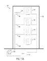
流体循環システムは、通常、余分な容量を備えて設計されるため、当該システムの全体的な動作または設計に悪影響を及さずに運動エネルギーを流体流から収穫することができる。本明細書に開示する装置および方法の原理は、図13Aおよび13Bに示す典型的な複数階構造用のHVACシステム300を非限定的に参照する文脈で例示している。開示する装置および方法はHVACシステムに限定されるものではなく、流体(液体、気体、液体および気体の混合物)が循環し若しくは流れる任意のシステムに広く応用できる。
Since fluid circulation systems are typically designed with extra capacity, kinetic energy can be harvested from the fluid flow without adversely affecting the overall operation or design of the system. The principles of the apparatus and method disclosed herein are illustrated in the context of a non-limiting reference to the exemplary
図13Aは、並列に構成されたファンコイル325を備える複数階構造302を例示したもので、全体を参照番号300で示している。前記ファンコイル325は、ポンプ330およびボイラー335に連結できる。各レベルのバランス弁340は、人為的な圧力損失を生じさせて水が下方レベルから上方レベルに移動するようにし、水が配管を上へ移動し続けるようにする上で役立つ。HVACシステム300のインデックスラン305は、通常、流体流の最も重要な経路であり、一般には「最上」(top)階(当該構造の最も高い(highest)階であるとは限らない)にわたる経路がインデックスランとして指定され、その最上階は、各ユニット、例えばファンコイル325により階の暖房または冷房需要を十分満たすだけでなく、約5〜約30%の安全マージンを備え、例えば最上階の最大冷房または暖房需要を満たし、転じて前記ポンプの全体的なサイズおよび能力を決定する。この需要を満たすよう設計されたシステムは、通常、前記最上階より低い全階の需要を満たす十分な流量および圧力を有する。前記インデックスランの「最上」階以下の各階では、前記インデックスラン300から利用可能な圧力および流量は、通常、それら各階の装置に必要な需要を上回る。特に、そのようなHVACシステムを運用する当該構造の下方階は、インデックスラン以外の経路を有し、通常、著しく過剰な流体圧力および流量が利用可能であり、それらの圧力および流量は特定階の需要を満たすよう絞られる(低減される)。そのような流体の絞り、すなわち圧力低減は、通常、前記流体に含まれる利用可能なエネルギーを、バランス弁、減圧弁を使って永続的に浪費することにより行われる。
FIG. 13A illustrates a
本開示の原理によれば、流体循環経路に装置を設置することにより、前記HVACシステム300の前記インデックスラン305以外の部分を流れる流体の過剰な圧力および体積に代表されるエネルギーを収穫することができる。そのような装置の非限定的な例としては、テスラタービンなどがあり、その基本構成はよく知られている。流体流は、1若しくはそれ以上のノズルで送られて当該流体の速度が高められ、テスラタービンの平行なディスク間に送られて当該タービンのディスクおよびシャフトに回転力をもたらす。前記シャフトの回転を使うと、(物理学的)仕事を直接行え(例えば、ファンブレードを回転させて空気に熱交換器を通過させる)、または発電装置を回転させることができる。電気エネルギーはファンの作動、システムの制御、または他の目的に使用でき、後日使用するため貯蔵し、または配電網に接続して戻すことができる。
In accordance with the principles of the present disclosure, by installing a device in a fluid circulation path, harvesting energy represented by excess pressure and volume of fluid flowing through portions of the
テスラタービンは、流体の著しい乱流または中断(圧力損失)を生じることなく、流体流から運動エネルギーを効率的かつ確実に収穫する潜在能力があるため、魅力的な装置である。当業者であれば、他の装置でも本明細書に開示する概念および方法に使用できることが明確に理解されるであろう。本開示は、いかなる特定のハーベスティング装置にも限定されるものではなく、テスラタービンは、本開示に適合した装置の非限定的な例として意図されている。 Tesla turbines are attractive devices because of their potential to efficiently and reliably harvest kinetic energy from a fluid stream without causing significant turbulence or interruption (pressure loss) of the fluid. Those skilled in the art will clearly understand that other devices may be used with the concepts and methods disclosed herein. The present disclosure is not limited to any particular harvesting device, and a Tesla turbine is intended as a non-limiting example of a device adapted to the present disclosure.
小型のエネルギーハーベスティング装置、例えばテスラタービンを使うと、必要な位置で電気エネルギーを生成できるため、HVACサブユニット、例えば特定の部屋または一部の空間用に機能する熱交換器に伴うシステムおよびファン装置の制御用に別個の給電装置を動作させる必要がなくなる。その結果、構造コストの点で大幅な節約が可能になる一方、テスラタービンは、必要な維持保全についても、HVACシステムでファンなどの駆動に使用される一般的な電動機より少なくすむはずである。 A small energy harvesting device, such as a Tesla turbine, can generate electrical energy where it is needed, so HVAC subunits, such as systems and fans associated with heat exchangers that function for specific rooms or spaces There is no need to operate a separate power supply for controlling the device. As a result, while savings are possible in terms of construction costs, Tesla turbines should also require less maintenance than typical motors used to drive fans and the like in HVAC systems.
図1は、本開示の態様に基づき、タービン駆動ファン装置10の一実施形態を例示したものである。このタービン駆動ファン装置10は、ハウジング11と、入口13と、出口14とを含むタービンアセンブリを含む。本開示全体にわたり使用される用語「ファン」とは、インペラー(羽根車)、ローター、または他の回転部材、例えば、ケーシングを伴う若しくは伴わないかご形インペラー12を意味し、通常、大量の流体、例えば空気を循環させるため使用される。HVACシステムでは、通常、多数のファンを使って熱交換器に空気を循環させ、建築物内の空気を加熱および/または冷却し、これを除湿する。各ファンは、通常、建築物の電源に接続された導体により供電され、サーモスタットまたは他の制御システムにより制御される。
FIG. 1 illustrates one embodiment of a turbine-driven
図2は、本開示の原理に基づき、エネルギーを抽出する方法の一例を示したものである。この方法は、抽出できる過剰なエネルギーを流体流が含むシステム、または建築物の電源との接続部からではなく例えば流体流から局所的なエネルギー生産が有利に行えるシステムを特定する工程から開始する(工程110)。この方法は、前記流体流からエネルギーを効率的に抽出するエネルギー抽出装置を選択および構成する工程を含む(工程120)。例えば、前記エネルギー抽出装置は、インデックスラン以外の経路位置に設置できるものである。前記エネルギー抽出装置は、例えば、テスラタービン、前記タービン駆動ファン装置10(図1に示す)、タービンアセンブリ200(図3に示す)などを含むことができる。前記システムおよびエネルギー抽出装置が決定されたら、前記システムの流体流の経路に前記装置を設置して、前記流体中の運動エネルギーをシャフトの回転エネルギーに変換できる(工程130)。次に、前記設置された装置を使って、仕事実施装置(図示せず)、例えばファン、発電機などを駆動できる(工程140)。前記設置された装置は、前記作業実施装置に連結できるドライブシャフトを含むことができる。 FIG. 2 shows an example of a method for extracting energy based on the principle of the present disclosure. The method starts with identifying a system in which the fluid stream contains excess energy that can be extracted, or that can advantageously produce local energy from the fluid stream, for example, rather than from a connection to a building power source ( Step 110). The method includes selecting and configuring an energy extraction device that efficiently extracts energy from the fluid stream (step 120). For example, the energy extraction device can be installed at a route position other than the index run. The energy extraction device may include, for example, a Tesla turbine, the turbine drive fan device 10 (shown in FIG. 1), a turbine assembly 200 (shown in FIG. 3), and the like. Once the system and energy extraction device are determined, the device can be installed in the fluid flow path of the system to convert kinetic energy in the fluid into rotational energy of the shaft (step 130). The installed device can then be used to drive a work execution device (not shown), such as a fan, generator, etc. (step 140). The installed device may include a drive shaft that can be coupled to the work execution device.
前記仕事実施装置が発電機である場合は、その仕事実施装置を従来の電気的構成要素(例えば、照明器具、ファン、コンピュータ、テレビ受像機、時計、ラジオなど)に接続して、その構成要素に供電できる。前記仕事実施装置は、例えば電源に供電して、外部、例えば配電網からの供電需要を軽減するよう構成できる。 If the work execution device is a generator, the work execution device is connected to conventional electrical components (eg, lighting fixtures, fans, computers, television receivers, watches, radios, etc.) Can supply electricity. The work execution apparatus can be configured to supply power to, for example, a power source and reduce power supply demand from the outside, for example, a distribution network.
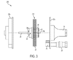
図3は、図1に示した前記タービン駆動ファン装置10に含めることができるタービンアセンブリ200の一例の分解図を示したものである。このタービンアセンブリ200、210は、流体循環システムの導管内の作動流体を受け取ってタービンハウジング22a、22b内に送る入口20を含む。前記導管は、例えば、水供給配管、HVAC供給配管、蒸気供給配管、ガス供給配管などであってよい。前記作動流体としては、水、グリコール、冷媒、蒸気、天然ガス、下水、原油、生活雑排水、または熱伝導、燃焼、または他の産業工程に使用される他の任意の流体などがある。アパートおよびホテルで使用される水または下水も、エネルギーを抽出可能な流体流を提供できる。出口21は、前記工程または流体循環システムに前記作動流体を戻す。前記ハウジング22a、22bは、タービン機構210周囲の空間を収容する。前記タービン機構210は、図3に見られるようにテスラタービン機構を含むことができる。このタービン機構210は、(作動流体が天然ガス、蒸気、または他の任意の可圧縮性流体である場合)複数の平坦で滑らかなディスク23を含むことができ、これらのディスク23は、少なくとも1つの軸方向に設置されたシャフト24によってハブ28に取り付けられ、ベアリング29a、29bにより支持される。前記複数の平坦で滑らかなディスク23は、利用される流体のタイプまたはその流体のレイノルズ数に応じてエッチングされた表面を有することができる。前記ベアリング29a、29bは、従来型、セラミックまたは磁気タイプのベアリングを含む任意タイプのものであってよく、前記タービン機構210が前記タービンハウジング22a、22b内で略無摩擦回転できるよう、前記タービン機構210を支持するよう構成できる。本明細書に開示する実施形態において、前記ディスク23は、中心に(軸方向に)位置し前記出口21と流体連通した排出(吐出)開口部を含む。これらのディスク23は、所定の間隔をあけた関係で、複数の連結ロッド26により、互いに、前記ハブ28に、またプレート27にも固定することができる。前記連結ロッド26は、圧力損失を軽減するよう水中翼形状(例えば、楕円形タイプの断面形状)に構成できる。前記ハブ28および/またはプレート27は、前記タービン機構210の回転中に望ましい慣性特性をもたらす「フライホイール」として作用するよう構成できる。プレート27は、ベアリング29b上の前記タービン機構210を軸方向に支持する位置を提供する。前記タービン機構210は、当該アセンブリの軸に沿って各ディスク23に出口開口部を含むことにより、作動流体と前記ディスク23間の接触部のらせん状経路の長さを最大限に伸ばすことができる。
FIG. 3 is an exploded view of an example of a
当業者であれば、前記タービン機構210の構成は、併用される特定の流体循環システム用に最適化できることが理解されるであろう。例えば、テスラタービンは、すべての流体にあてはまる2つの基本特性―粘着力および粘性―に依存する。テスラタービンの文脈におけるこれら2特性の特定の作用はよく知られており、以下、本明細書で詳述する。これら2つの特性は、前記タービン機構200において流体からローターへ、またはその逆にエネルギーを伝達するよう協働する。
One skilled in the art will appreciate that the configuration of the
タービン機構、例えばテスラタービンを設計する際は、各種作動流体の種々の特性を考慮すべきである。入力流量および圧力、許容される出力流量および圧力のほか、タービンで生み出すべき望ましい回転速度およびトルクも、本開示に係るエネルギー抽出装置の設計において考慮すべき要素である。非限定的な例により、前記ディスク23の内径および外径ならびに厚さと、当該ディスク23間の間隔と、当該ディスク23の数と、ノズル25の構成と、排出開口部および出口21とは、すべて、前記タービン機構210の動作特性に影響を及ぼし、これらを調整することで、所与の流体循環システムについてエネルギー抽出の効率を最大化するとともに所定の回転速度およびトルクをもたらすことができる。前記ディスクを構築する材料もタービン動作に影響し、1つまたは複数の薄く平坦で剛性の滑らかな金属ディスクであって、高回転速度での変形に耐えるマイクロ流路表面を備えたものが最も望ましい。複合材料を、例えばKevlarまたは炭素繊維(カーボンファイバー)で強化したものは、テスラタービンの構築に良好に使用されてきている。ただし、セラミックまたはガラスで強化した材料の使用も推奨される。大部分の流体循環システムでは標準的な流体、例えば水または空気を使用しており、有限な範囲内の流体流および圧力特性を有する可能性が高いため、比較的少数のエネルギー抽出装置で大多数のシステムに対応させることができる。
When designing a turbine mechanism, such as a Tesla turbine, various characteristics of various working fluids should be considered. Input flow rate and pressure, allowable output flow rate and pressure, as well as the desired rotational speed and torque to be generated in the turbine are also factors to consider in the design of the energy extraction device according to the present disclosure. By way of non-limiting example, the inner and outer diameters and thickness of the
そのようなディスクは、テスラタービン装置の元の設計から公知の滑らかで平坦かつ平行な表面により構成できる。あるいは、各ディスクを表面処理して特定の流体に対する表面の粗さを高めることができ、隣接するディスク間の境界層を厚くして隣接するディスク表面間の間隔を伸縮させるよう各ディスクを可変厚さにすることもできる。また、ディスク表面は、流体流の方向に対する当該ディスク表面の配向角度を変えることもできる。本開示の態様は、ディスク排出(吐出)開口部のサイズを変更してタービン内の流体流に対応し、タービンの動作特性を特定の作動流体および流体循環システムに整合させることである。例えば、第1のディスクの吐出開口部は、その下流にあるディスク(例えば、第10のディスク)の吐出開口部より比較的低い体積の流体を受け取るようにできる。前記吐出開口部を変化させると、一部の流体に役立つ一方、他の流体には役立たない。 Such a disk can be constituted by a smooth, flat and parallel surface known from the original design of the Tesla turbine device. Alternatively, each disk can be surface treated to increase the surface roughness for a particular fluid, and each disk can be made to have a variable thickness to increase the spacing between adjacent disk surfaces by increasing the boundary layer between adjacent disks. You can also make it. The disk surface can also change the orientation angle of the disk surface relative to the direction of fluid flow. An aspect of the present disclosure is to change the size of the disk discharge (discharge) opening to accommodate fluid flow in the turbine and to match the operating characteristics of the turbine to a particular working fluid and fluid circulation system. For example, the discharge opening of the first disk can receive a relatively lower volume of fluid than the discharge opening of the downstream disk (eg, the tenth disk). Changing the discharge opening is useful for some fluids but not for other fluids.
図10および11は、本開示の原理に基づいて構成されたタービン機構の非限定的な例を図示したものである。図10および11を参照すると、前記タービン機構は、軸流排出開口部51を有したディスク23a〜23j(単独で若しくは一括して「23」と参照)を含むことができ、前記軸流排出開口部51は、図10に示すように、当該タービンの入口端より排出端のほうで大きく構成される。本開示の目的は、最低限の圧力損失で作動流体から効率的にエネルギーを収穫することである。本開示のさらに別の態様は、複数のノズルを使って、一定間隔で、前記ディスク23外周の周囲に流体を導入することに関する。このような構成により境界層が「供給」されて流体(およびディスク)の最大速度が保たれるため、流体から前記ディスクに伝達される力が最大化されて、利用可能な流体流の粘着力および有効活用の最大化が実現し、当該タービンの効率が改善される。
FIGS. 10 and 11 illustrate non-limiting examples of turbine mechanisms constructed in accordance with the principles of the present disclosure. Referring to FIGS. 10 and 11, the turbine mechanism may include
あるいは、前述のように、水などの一部の流体の場合、このようなタービンの効果を最大化するには、前記ディスクの外径と内径の比が高くなることは明らかである。可圧縮性流体と対照的に、前記ディスク間における非圧縮性流体の速度は、そのような流体が当該ディスク構成内で経る流路の長さとともに急激に低下する。そのため、「ディスク」と対照的に「リング」を有することで、そのようなディスク間の流体速度が最大化され、前記タービンの効率がさらに改善される。高速流体の複数の入口(ノズル)を、ディスク内で許容される最低限の流速で、同一場所に配置すると、そのようなタービンの効率が最大限に伸ばされる。一部の実施形態において、前記複数のディスクのうち少なくとも1つは、外径対内径の比が小さい、例えば比が約2"未満のリングであってよい。 Alternatively, as described above, in the case of some fluids such as water, it is clear that the ratio of the outer diameter to the inner diameter of the disk is high in order to maximize the effect of such a turbine. In contrast to compressible fluids, the speed of incompressible fluids between the disks rapidly decreases with the length of the flow path through which such fluids travel within the disk configuration. Thus, having “rings” as opposed to “disks” maximizes the fluid velocity between such disks and further improves the efficiency of the turbine. Placing multiple inlets (nozzles) of high speed fluid at the same location with the lowest flow rate allowed in the disk maximizes the efficiency of such turbines. In some embodiments, at least one of the plurality of disks may be a ring having a small outer diameter to inner diameter ratio, eg, a ratio of less than about 2 ″.
前記ディスク間隔は、前記タービンの効率にとって非常に重要である。流体の初期速度は望ましいRPMを達成するため可能な限り高くする必要がある一方で、前記ディスク間の流体のレイノルズ数は可能な限り低くする必要があるため、前記レイノルズ数を軽減するための妥協が要求される。前記ディスク間の間隔は、ナノメートルまたはマイクロメートルのスケールまで狭められることから、ナノまたはマイクロ技術を使って前記テスラタービンの効率を最大限に伸ばすこと、ひいては流体とディスクの接触表面積を広くしてそれらの間のエネルギー伝達を高めることは至って実現可能である。 The disk spacing is very important for the efficiency of the turbine. The initial velocity of the fluid needs to be as high as possible to achieve the desired RPM, while the Reynolds number of the fluid between the disks needs to be as low as possible, so a compromise to reduce the Reynolds number. Is required. The spacing between the disks can be reduced to the nanometer or micrometer scale, so that nano or micro technology can be used to maximize the efficiency of the Tesla turbine and thus increase the contact surface area between the fluid and the disk. Increasing the energy transfer between them is quite feasible.
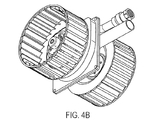
図1、10、および11に見られるように、前記タービン装置には、それぞれ、シャフトを含めなくてもよく、あるいは図4Aおよび4Bに見られるように、双方の軸方向に延長する単一のシャフト24または複数のシャフトを含めることができる。2つのシャフトを伴う一実施形態では、例えば1つまたは複数のインペラーファン、ファン、および発電機、またはこれらの任意の組み合わせの連結が可能になる。シャフト24は、作動流体の影響下で前記ディスク23により生成される回転力と、仕事実施装置、例えばファン、発電機などとの間にある連結機構の非限定的な例として意図されている。企図される他の構成としては、プレート27またはハブ28上かその付近に、前記タービン機構から仕事を行う回転力を伝達する連結部を提供するなどがある。その連結部は、歯車、磁性、摩擦その他による適切な構成とすることができる。前記仕事は、図1、4A、および4Bに見られるように、前記タービン装置をファンに回転式に直接連結して行うことができる。前記タービンアセンブリにより生成される回転力を発電機または交流発電機30に連結すると(図4A)、同時に使用でき若しくは電池(図示せず)に貯蔵して後日使用できる電気エネルギーを生成できる。電池は、エネルギー貯蔵装置の非限定的な例の1つであり、これには任意の適切な代替装置、例えばキャパシタなどを含めることができる。あるいは、収穫された電気エネルギーを、いわゆる「逆メータリング」(reverse−metering)のため、配電網に接続された1若しくはそれ以上のインバータ装置に送達することもできる。
As seen in FIGS. 1, 10, and 11, the turbine apparatus may not include a shaft, respectively, or as seen in FIGS. 4A and 4B, a single axially extending both. A
図3を参照すると、前記タービン機構210の効率を最大化するには、1若しくはそれ以上のノズル25を通じて前記タービンハウジング22a、22bに作動流体を導入できる。当業者であれば認識および理解されるように、前記ノズル25は、所与の流体循環システムについてタービンの回転速度および力を最大化するよう選択された一定の位置、方向、および速度で、前記ハウジング22a、22bに作動流体を導入することができる。
Referring to FIG. 3, to maximize the efficiency of the
図6は、図3に示すタービンに適合したノズルの代替実施形態をいくつか示したものである。当業者であれば、作動流体から前記ディスク23へのエネルギー伝達の効率を最大限に伸ばす上で、種々のノズル構成、例えば図6に例示したものを使用できることが明確に理解されるであろう。ノズルの設計および配置は、特定のタービン機構の作動流体、流体循環システムの流れ特性、および物理的寸法およびレイアウトを補完するよう選択できる。種々のノズルを使うと、当該タービンの残りの寸法および特性を保ちながら、所与のタービンアセンブリを「調整」できる可能性がある。
FIG. 6 shows several alternative embodiments of nozzles adapted to the turbine shown in FIG. Those skilled in the art will clearly understand that various nozzle configurations, such as that illustrated in FIG. 6, can be used to maximize the efficiency of energy transfer from the working fluid to the
作動流体が水または他の非圧縮性流体である場合、前記タービンの前記作動流体および前記ディスク23の接触を最大化するよう前記ノズルを構成すると、前記作動流体と前記ディスク間の境界層効果を最大化できる。
If the working fluid is water or other incompressible fluid, configuring the nozzle to maximize contact between the working fluid of the turbine and the
作動流体が気体(圧縮性流体)である場合は、例えばベンチュリ、デラバル、または他の流体力学原理を使って、前記ディスク23間の空間に入る前記作動流体の速度を最大化するよう前記ノズルを構成することができる。
If the working fluid is a gas (compressible fluid), the nozzle can be configured to maximize the speed of the working fluid entering the space between the
あるいは、前記ノズルの構成、位置、または角度配向を変えて、所与の流体循環システムでの流体流の変化に対応することもできる。また非限定的な一例として、可変構成のノズルを使うと、前記タービン機構の速度およびトルクを制御して、空気循環の需要にタービン出力を合わせることもできる。電子コントローラ(図示せず)を通信リンク経由で通信可能に連結し、例えば、前記流体循環システム内または関連HVACシステム内に配置可能なセンサー(図示せず)からのフィードバックを使って、前記ノズルの構成を変更し、前記タービンに連結されたファンを制御するよう構成することもできる。タービン動作の制御は、例えばファンの動作範囲全体にわたり線形とすることができ、または段階的に提供できる(低、中、高)。 Alternatively, the configuration, position, or angular orientation of the nozzle can be varied to accommodate changes in fluid flow in a given fluid circulation system. As a non-limiting example, the use of a variable configuration nozzle can control the speed and torque of the turbine mechanism to match the turbine output to the demand for air circulation. An electronic controller (not shown) is communicatively coupled via a communication link, for example using feedback from a sensor (not shown) that can be located in the fluid circulation system or in an associated HVAC system. The configuration can be changed to control a fan connected to the turbine. Control of turbine operation can be linear, for example, over the entire operating range of the fan, or can be provided in stages (low, medium, high).
前記回転出力シャフトは、前記タービン内で磁力により前記回転ディスク23に連結できる。磁気結合を用いると、前記タービンハウジング22a、22bを貫通するシャフト24を密封する必要がなくなり、作動流体の吐出が容易になって、本明細書に開示するエネルギー抽出装置の摩擦力を軽減し効率を改善することができる。例えば、複数の磁石を前記タービン機構に埋め込むと、隣接しあう各前記ディスクを互いに浮揚させることができる。例えば、前記ディスクのうち1若しくはそれ以上に磁石を含め、そのディスクの表面全体に磁石を均等に分散させることができる。
The rotating output shaft can be connected to the
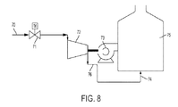
図5は、本開示に基づいてタービン駆動ファン装置を利用するHVACシステムの構成(またはシステム)の概略図である。図5を参照すると、この構成は、熱交換器43を伴うタービン駆動ファン44、48を含む。当該システムは流体導管41を含み、この流体導管41は、例えば、水、冷媒などを含みうる作動流体源に前記熱交換器43を連結する。その作動流体は、望ましい作用に応じて加熱または冷却できる。このシステムには、調節弁42をさらに含めて、サーモスタット45により表される関連HVACシステムからの需要に基づき、前記熱交換器43への作動流体の流れを調節できる。作動流体は、もう1つの調節弁46を経て前記熱交換器43からタービン機構48へ通過する。圧力センサー47a、47bは、前記タービン48の前記入口および吐出部にそれぞれ連結できる。タービンの吐出部は作動流体循環システム49の返還側として連結でき、この作動流体循環システム49は図示した例ではHVACシステムであり、その作動流体は、1つの位置から別の位置へと熱交換器43を介して熱エネルギーを伝導するため使用される。ファン44は、前記熱交換器43を通じて空気を循環させるようタービン48に連結できる。調節弁42、46は、前記サーモスタットTまたは他のコントローラ45に連結できる。前記タービン48への流量は、調節弁42、46の状態に応じて異なることが明確に理解されるであろう。前記タービンの出力は、図7に示すように、ファン、インペラー、および/または発電機に結合できる。
FIG. 5 is a schematic diagram of a configuration (or system) of an HVAC system that utilizes a turbine-driven fan device in accordance with the present disclosure. Referring to FIG. 5, this configuration includes turbine driven
発電機は、電池に接続でき、またはインバータに接続したのち例えば配電網に接続でき、あるいは現場のエネルギー需要または貯蔵能力に応じてエネルギー貯蔵装置および配電網の何らかの組み合わせに接続できる。 The generator can be connected to a battery, or connected to an inverter and then connected to, for example, a power grid, or can be connected to any combination of energy storage devices and power grids depending on on-site energy demand or storage capacity.
図9は、本開示の態様に係るタービン機構の一実施形態の斜視図であり、そのハウジングの端部および一部のディスクは明瞭性のため除いている。図9を参照すると、このタービン機構は、前記ディスク23に向けて流体を方向付けるノズル25用に6つの位置を画成するハウジングを含む。前記ノズル25は、それぞれ前記ディスク23へと流体が方向付けられる角度を調整できるよう構成されている。これにより、特定の流体および他のシステムパラメータでの動作用に、前記タービン機構のチューニングまたは調整が容易になる。前記タービン機構は、当該タービンおよび前記ディスクアセンブリ23を貫通して軸方向に延長する中心シャフト24を含む。前記ディスク23は、スペーサー(および/または磁力)により離間された状態で保たれ、ロック用カラー(つば部)100により前記シャフト24に固定される。
FIG. 9 is a perspective view of one embodiment of a turbine mechanism according to aspects of the present disclosure, with the housing end and some disks removed for clarity. Referring to FIG. 9, the turbine mechanism includes a housing that defines six positions for a
図10および11は、本開示の態様に基づき、タービン機構用構成の非限定的な例の分解図および断面図を示したものである。図10および11のタービン機構実施形態は、上述のとおり、各ディスクの軸中心に排出開口部51を有するディスク23a〜23jを使用している。この構成では、各ディスクとの流体接触(および結果的に得られる粘着力)が最大化され、前記タービンの効率が高まる可能性がある。前記複数のディスク23a〜23jは出口開口部を有し、この出口開口部は、移動する作動流体およびディスクの接触部のらせん状経路の長さを最大限に伸ばす。これらディスク23a〜23jは、各ディスクの開口部102を貫通する一対のロッド103で連結され、当該アセンブリの各端部でロック用カラー100に連結される。前記ロック用つば部100はシャフト部分24a、24bを取り囲んで支持し、転じて当該アセンブリの各軸端部においてベアリング104上で回転するタービン部品を支持する。
10 and 11 show exploded and cross-sectional views of a non-limiting example of a turbine mechanism configuration in accordance with aspects of the present disclosure. The turbine mechanism embodiment of FIGS. 10 and 11
図9〜11に例示した実施形態用のタービンハウジングは、出口21と連通したノズル25および6つの排出開口部用に6つの位置を画成する同様な構成を有する。その代替実施形態では、より多数または少数のノズルまたは出口を使用できる。さらに、前記ノズルは、ディスク23間の空間へ流体が方向付けられる際の流量および流れ方向について角度が調整できる。これらのノズル25は、特定設備の流体および要件に応じ、特定の位置へと種々の流体体積を方向付けるよう構成できる。非限定的な一例では、ノズル内の円錐形の内部経路により、最初の2ディスク間よりも最後の2ディスク間で小体積の流体が送られる。
The turbine housing for the embodiment illustrated in FIGS. 9-11 has a similar configuration that defines six positions for the
図12Aは、本開示の原理に基づいて構成されたタービンに埋め込まれたローターの斜視図であり、図12Bはそのローターの断面図である。ディスク32は上述したとおりでよいが、この例では前記開口部51が著しく大きく、例えばディスク面積の約70%〜約90%、またはディスク32の面積の約90%である。この構成は、水および他の液状流体で適切に作用する。図10および11のディスク構成は、気体で適切に作用する傾向がある。
FIG. 12A is a perspective view of a rotor embedded in a turbine constructed in accordance with the principles of the present disclosure, and FIG. 12B is a cross-sectional view of the rotor. The
図7は、本開示に係るエネルギー抽出装置の代替設備の一例を示したものである。上記で図5について提供された説明に加え、図に示した設備は、前記タービン48と、発電装置30と、電池31と、コントローラ50と、調節弁42、46とを含む。前記コントローラ50は、導電体を通じて電池31または他のエネルギー貯蔵装置に接続できる。このコントローラ50は、導電体を通じて電力用の電池および調節弁42、46に接続できる。このコントローラ50は恒温装置の形態であってよく、またはセンサー、フィードバックループなどに接続されたより高度なマイクロコントローラを有することができる。このコントローラ50は、1若しくはそれ以上の通信リンク経由またはネットワーク経由で建築物のシステムと直接通信するよう構成できる。ネットワーク接続されたコントローラであれば、前記タービンシステムの遠隔制御を可能にし、前記タービンおよび関連システムからのデータ収集とそれによるシステム機能および効率の監視を実現できる。
FIG. 7 shows an example of an alternative facility for the energy extraction device according to the present disclosure. In addition to the description provided above for FIG. 5, the equipment shown in the figure includes the
図8は、本開示の原理に基づき、本明細書に開示するエネルギー抽出装置のさらに別の代替応用を示したものである。図8を参照すると、このシステムは、強制通風ボイラー75に強制空気を提供するよう構成されたタービン駆動ファン73およびタービン72を含む。前記タービン72は、事前に圧力調整された燃焼流体(天然ガス、暖房用油、プロパン、LNG、LPG、または他の可燃性流体)の入射流70からエネルギーを抽出するよう構成されており、供給配管70および流量調節装置71により適切な安全および制御装置が供給される。あるいは、前記タービンとそれに伴うノズルが調節弁71の機能を果たして、必要な圧力低下を提供しながら、その過程でエネルギーを抽出できる。前記タービン72の出力はファン73に結合され、そのファン73が燃焼の必要に応じてバーナー74および/または燃焼室75に空気を導入する。前記タービン駆動ファン装置の出口76は、前記バーナーの前記供給配管に連結され、必要に応じて燃焼流体を供給する。有利なことに、燃焼流体の需要が増加すると結果的に流体流量も増えて、前記タービンに連結されたファン73からの気流増加も可能になる。
FIG. 8 illustrates yet another alternative application of the energy extraction device disclosed herein based on the principles of the present disclosure. Referring to FIG. 8, the system includes a
本開示の態様は、流体力学の原理を例示するため教室および研究室の環境で使用できる教育用キットに関する。本開示に係る教育用キットの非限定的な一例は、図3で説明したタービン駆動ファン装置の全部品と併せて、管、ならびにクイックコネクト、押し込み式、あるいはシャークティース形(shark−teeth)またはシャークバイト形(shark−bite)の継手と、手動(および/または電動)バルブのセットと、マイクロプロセッサであってよいコントローラと、発電機と、ディスプレイ(例えば、LEDディスプレイ、LCDディスプレイ、またはLED照明など)と、電線セットと、水用の染料と、バケツと、水用ホースと、インペラーと、送水ポンプとを有する。前記キットには、流体力学の原理を1若しくはそれ以上例示するよう設計された実験について記載した印刷形態、デジタル、またはオンラインの資料を添えることができる。本明細書に開示するこのキットは、私立および公立学校のK〜12年生(幼稚園年長〜高校3年生)、大学、または個人用教育の目的での科学および物理学コースを補足する上で使用できる。このキットは、流体力学、電磁気学、発電、および持続可能性(サステナビリティ)の基本法則に関する見識を提供できる。また、このキットは、長期的な利点が示されているインタラクティブな学習体験を参加型を児童・生徒・学生に提供する。 Aspects of the present disclosure relate to educational kits that can be used in classroom and laboratory environments to illustrate the principles of hydrodynamics. A non-limiting example of an educational kit according to the present disclosure includes a tube and a quick connect, push-in, or shark-teeth or all of the components of the turbine-driven fan device described in FIG. A shark-bit joint, a set of manual (and / or motorized) valves, a controller that may be a microprocessor, a generator, and a display (eg, LED display, LCD display, or LED lighting) Etc.), an electric wire set, a water dye, a bucket, a water hose, an impeller, and a water pump. The kit can be accompanied by printed, digital, or on-line materials describing experiments designed to illustrate one or more of the principles of hydrodynamics. This kit as disclosed herein is used to supplement science and physics courses for private and public school K-12 grade (kindergarten to senior high school), university, or personal education purposes it can. The kit can provide insight into the fundamental laws of fluid mechanics, electromagnetism, power generation, and sustainability. The kit also provides children, students and students with an interactive learning experience that shows long-term benefits.
本明細書に開示するエネルギー抽出装置は、建築物内で使用して、当該建築物のHVACシステム用のファンに給電できる。エネルギー抽出装置は、ボイラー室およびHVAC端末装置が置かれる空間に配置構成できる。HVAC目的で本発明が利用可能な建築物は、これに限定されるものではないが、住宅、集合住宅、事務所建築物、病院および医療施設、公共および連邦建築物、博物館および美術館、空港、ホテル、および他の娯楽用建築物、工場などを含む。 The energy extraction device disclosed herein can be used in a building to power a fan for the HVAC system of the building. The energy extraction device can be arranged in a space where the boiler room and the HVAC terminal device are placed. Buildings in which the present invention can be used for HVAC purposes include, but are not limited to, houses, apartment buildings, office buildings, hospitals and medical facilities, public and federal buildings, museums and galleries, airports, Includes hotels and other recreational buildings, factories, etc.
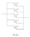
本明細書に開示するエネルギー抽出装置を利用すると、飲用水道、温水または冷水用水道、蒸気暖房(スチーム暖房)配管、天然ガス供給配管、または冷却配管、あるいは利用可能な他の任意のプロセス流体、建築物内を循環する流体の収穫可能なエネルギーから発電できる。建築物の配管システムからのエネルギー抽出効率を最大化するには、開示した複数のエネルギー抽出装置を、図13Cに示すように並列に連結して利用可能な水流を最大限に活用し、タービンの並列アレイを生み出すことができる。例えば、100GPMの水流が利用でき、タービンの最適性能が10GPMであるとする。その場合は、10個のタービンを並列に連結すると、建築物内のそのような位置で利用可能な流量をすべて受容できる。建築物内のそのような位置で利用可能な圧力が100水柱フィートで、単一のタービンが10水柱フィートの水圧しか消費しないと仮定すると、図13Dに示すように10個のタービンを直列に連結して、ポンプにより生成済みの利用可能な水頭圧を最大限に活用することができる。これら2つのタービン連結方法(直列および並列)を組み合わせて利用すると、図13Eに示すように、建築物内の利用可能な流体エネルギーを最大限に活用できる。 Utilizing the energy extraction device disclosed herein, drinking water, hot or cold water, steam heating (steam heating) piping, natural gas supply piping, or cooling piping, or any other process fluid available It can generate electricity from the harvestable energy of the fluid circulating in the building. In order to maximize the energy extraction efficiency from the building piping system, the disclosed energy extraction devices can be connected in parallel as shown in FIG. Parallel arrays can be created. For example, assume that a 100 GPM water flow is available and the optimum performance of the turbine is 10 GPM. In that case, 10 turbines connected in parallel will receive all the flow rates available at such locations in the building. Assuming that the available pressure at such a location in the building is 100 feet of water and a single turbine consumes only 10 feet of water, connect 10 turbines in series as shown in FIG. 13D. Thus, the available water head pressure generated by the pump can be utilized to the maximum. When these two turbine connection methods (series and parallel) are used in combination, the available fluid energy in the building can be maximized as shown in FIG. 13E.
商業用送水ポンプは、通常非常に大型で、高層建築物には著しい水頭圧が必要とされる。さらに、大規模な冷水用途では、冷水を常に循環させて沈殿物その他の不純物の蓄積を回避する必要がある。本明細書に開示するエネルギー抽出装置および方法は、建築物内における付加的な水流循環を必要としない。すでに建築物全体へのポンプ送水にエネルギーが消費されているので、本明細書に開示するエネルギー抽出装置は、その同じ利用可能な流体流を利用して、例えばファンの運用またはエネルギーの生成に付加的なエネルギーを必要とせずに動作する。それを行うために必要なすべてのエネルギーは、すでに建築物内で循環している水が提供する。 Commercial water pumps are usually very large and require significant head pressure for high-rise buildings. Furthermore, in large-scale cold water applications, it is necessary to circulate cold water constantly to avoid accumulation of precipitates and other impurities. The energy extraction apparatus and method disclosed herein does not require additional water circulation within the building. Since energy is already consumed in pumping water throughout the building, the energy extraction device disclosed herein can use that same available fluid flow to add to, for example, fan operation or energy generation. To work without the need for energy. All the energy needed to do that is provided by the water already circulating in the building.
20階建ての建築物を想定し、その各階に50のファンコイルユニット(fan coil units:FCUs)があり、その各々が100W消費し、その建築物が1日12時間、350日間、すなわち4200時間稼働する場合は、FCUs内のファンに給電する電気エネルギー消費量だけでも420,000kWhになる。10¢〜15¢/kWhのレートでは、年間のエネルギー節約量は$42〜$65/FCUにもなる。建築物が1,000FCUsを有する場合を考慮すると、潜在的なエネルギー節約量は年間$42,000〜$63,000にもなりうる。ファンコイルユニット付きの部屋が1000室あるホテルまたは病院で、各部屋が年中無休で稼動する場合、年間876MWhが消費される。これをタービン駆動ファン装置に交換すると、潜在的なエネルギー節約量は年間$87,600〜$130,000にもなりうる。本開示は電源への接続が不要であるため、電気設備コストには著しい節約が実現される。電気設備のコスト削減は広い範囲―$500〜$1,000超/FCUにわたり、初期のコスト節約は$500,000〜$1,000,000超になる。 Assuming a 20-story building, there are 50 fan coil units (FCUs) on each floor, each of which consumes 100 W, and the building is 12 hours a day, 350 days, or 4200 hours When operating, the amount of electric energy consumed to supply power to the fans in the FCUs alone is 420,000 kWh. At rates of 10 ¢ to 15 ¢ / kWh, the annual energy savings can be as much as $ 42 to $ 65 / FCU. Considering the case where the building has 1,000 FCUs, the potential energy savings can be as much as $ 42,000 to $ 63,000 per year. If a hotel or hospital has 1000 rooms with fan coil units, and each room operates 24 hours a day, 876 MWh is consumed annually. If this is replaced with a turbine-driven fan device, the potential energy savings can be as much as $ 87,600 to $ 130,000 per year. Because the present disclosure does not require connection to a power source, significant savings in electrical equipment costs are realized. The cost savings for electrical equipment range widely-ranging from $ 500 to over $ 1,000 / FCU, with initial cost savings ranging from $ 500,000 to over $ 1,000,000.
図13Bは、本開示の原理に基づいて構成された、タービンを備える複数階構造の代替実施形態を例示したものである。図13C〜13Eについて、タービン320は本明細書で説明するタービンのいずれでもよい。前記タービン320は異なる階に設置できる。前記タービン320およびファンコイル325は、バランス弁340と、ポンプ330と、ボイラー335とに連結できる。
FIG. 13B illustrates an alternative embodiment of a multi-storey structure with a turbine constructed in accordance with the principles of the present disclosure. 13C-13E, the
図13Cは、本開示の原理に基づいて構成された、並列に構成されたタービンを例示したものである。図13Dは、本開示の原理に基づいて構成された、直列に構成されたタービンを例示したものである。図13Eは、本開示の原理に基づいて構成された、並列および直列の双方に構成されたタービンを例示したものである。図13C〜13Eの構成は、図13Aおよび13Bと関連して示すように、ポンプ330、ボイラー335、バランス弁340、およびファンコイル325を含めて、同様な態様で実装できる。
FIG. 13C illustrates a turbine configured in parallel, configured in accordance with the principles of the present disclosure. FIG. 13D illustrates a series of turbines configured in accordance with the principles of the present disclosure. FIG. 13E illustrates a turbine configured in both parallel and series configured in accordance with the principles of the present disclosure. The configuration of FIGS. 13C-13E can be implemented in a similar manner, including
以上、例示的な実施形態により本開示を説明したが、当業者であれば、添付の請求項の要旨を逸脱しない範囲で、本開示に修正を加えて実施できることが理解されるであろう。これらの例は、単に例示的なものであり、本開示に考えられるすべての設計、実施形態、適用、または変更形態を網羅的にリストすることを意図したものではない。 Although the present disclosure has been described above by way of exemplary embodiments, those skilled in the art will appreciate that the present disclosure can be modified and implemented without departing from the spirit of the appended claims. These examples are merely illustrative and are not intended to be an exhaustive list of all possible designs, embodiments, applications, or modifications contemplated by this disclosure.
Claims (27)
ハウジングと複数のディスクとを含み、前記移動する流体から運動エネルギーを収穫する少なくとも1つのタービンアセンブリと、
前記複数のディスクを駆動するために、前記流体導管から前記移動する流体を受け取って、前記移動する流体を前記タービンハウジング内に方向付ける入口と、
前記移動する流体を前記タービンハウジングから前記流体導管に戻すための出口と
を有し、
前記複数のディスクのうち少なくとも1つは、前記移動する流体とディスクの接触部のらせん状経路の長さを最適化する出口開口部を有するものである、
エネルギー抽出システム。 An energy extraction system installed at off-index run locations other than the index run of the fluid circulation system and harvesting energy in the fluid moving in the conduit,
At least one turbine assembly including a housing and a plurality of disks for harvesting kinetic energy from the moving fluid;
An inlet for receiving the moving fluid from the fluid conduit and directing the moving fluid into the turbine housing to drive the plurality of disks;
An outlet for returning the moving fluid from the turbine housing to the fluid conduit;
At least one of the plurality of disks has an outlet opening that optimizes the length of the spiral path of the moving fluid and disk contact portion.
Energy extraction system.
水、
グリコール、
冷媒、
原油、
下水、
生活雑排水、
蒸気、
気体、または、
他の任意の非ニュートン流体
を有するものであるシステム。 The system of claim 1, wherein the moving fluid is
water,
Glycol,
Refrigerant,
crude oil,
sewage,
Miscellaneous wastewater,
steam,
Gas or
A system that has any other non-Newtonian fluid.
前記シャフトに連結され、前記回転エネルギーを受け取るように構成された仕事実施装置を有するものであるシステム。 The system of claim 13, further comprising:
A system comprising a work performing device coupled to the shaft and configured to receive the rotational energy.
前記循環システムのインデックスラン以外の経路位置を特定してエネルギー抽出装置を設置する工程と、
前記エネルギー抽出装置の入口を前記導管の一部に連結して前記移動する流体を前記導管から受け取る工程と、
前記エネルギー抽出装置の出口を前記導管の別の一部に連結して前記移動する流体を前記導管に戻す工程と
を有し、
前記エネルギー抽出装置は、前記導管内の前記移動する流体の運動エネルギーを利用して、当該運動エネルギーを回転エネルギーに変換するタービンアセンブリを有する
方法。 A method for harvesting energy in a moving fluid in a conduit of a fluid circulation system arranged in series with a balance valve, comprising:
Identifying a path position other than the index run of the circulation system and installing an energy extraction device;
Receiving the moving fluid from the conduit by connecting an inlet of the energy extraction device to a portion of the conduit;
Connecting the outlet of the energy extraction device to another part of the conduit to return the moving fluid to the conduit;
The energy extraction device comprises a turbine assembly that utilizes the kinetic energy of the moving fluid in the conduit to convert the kinetic energy into rotational energy.
ハウジングと複数のディスクとを含み、前記移動する流体から運動エネルギーを収穫する少なくとも1つのタービンアセンブリと、
前記複数のディスクを駆動するために、前記流体導管から前記移動する流体を受け取って、前記移動する流体を前記タービンハウジング内に方向付ける入口と、
前記移動する流体を前記タービンハウジングから前記流体導管に戻すための出口と
を有するエネルギー抽出装置。 An energy extraction device that is coupled to a path position other than the index run of the fluid circulation system and harvests kinetic energy in the fluid moving in the conduit,
At least one turbine assembly including a housing and a plurality of disks for harvesting kinetic energy from the moving fluid;
An inlet for receiving the moving fluid from the fluid conduit and directing the moving fluid into the turbine housing to drive the plurality of disks;
And an outlet for returning the moving fluid from the turbine housing to the fluid conduit.
Applications Claiming Priority (3)
| Application Number | Priority Date | Filing Date | Title |
|---|---|---|---|
| US201462016162P | 2014-06-24 | 2014-06-24 | |
| US62/016,162 | 2014-06-24 | ||
| PCT/US2015/036730 WO2015200134A1 (en) | 2014-06-24 | 2015-06-19 | Energy extraction apparatus and method |
Publications (2)
| Publication Number | Publication Date |
|---|---|
| JP2017527742A true JP2017527742A (en) | 2017-09-21 |
| JP2017527742A5 JP2017527742A5 (en) | 2018-06-14 |
Family
ID=54938691
Family Applications (1)
| Application Number | Title | Priority Date | Filing Date |
|---|---|---|---|
| JP2017521066A Pending JP2017527742A (en) | 2014-06-24 | 2015-06-19 | Energy extraction apparatus and method |
Country Status (9)
| Country | Link |
|---|---|
| US (1) | US20170205108A1 (en) |
| EP (1) | EP3161262A4 (en) |
| JP (1) | JP2017527742A (en) |
| CN (1) | CN106574501A (en) |
| AU (1) | AU2015280321A1 (en) |
| MA (1) | MA40693A (en) |
| RU (1) | RU2017100041A (en) |
| SG (1) | SG11201610661SA (en) |
| WO (1) | WO2015200134A1 (en) |
Families Citing this family (10)
| Publication number | Priority date | Publication date | Assignee | Title |
|---|---|---|---|---|
| IT201600132467A1 (en) | 2017-01-04 | 2018-07-04 | H2Boat | LIMIT LAYER TURBO EXTENSION AND REVERSE CYCLE MACHINE PROVIDED WITH SUCH TURBO-EXPANDER |
| CN107124071B (en) * | 2017-06-13 | 2024-03-15 | 浙江大学 | Integrated ocean current energy collection device |
| US11493275B2 (en) * | 2017-10-10 | 2022-11-08 | Tps Ip, Llc | Oven with renewable energy capacities |
| US11299925B2 (en) | 2017-10-11 | 2022-04-12 | Tps Ip, Llc | Oven with split doors |
| US11585701B2 (en) | 2017-10-27 | 2023-02-21 | Tps Ip, Llc | Intelligent oven |
| CN117072471A (en) | 2017-12-22 | 2023-11-17 | 台达电子工业股份有限公司 | Fan with fan body |
| US11346560B2 (en) | 2017-12-29 | 2022-05-31 | Tps Ip, Llc | Oven wall compositions and/or structures |
| WO2019220491A1 (en) * | 2018-05-14 | 2019-11-21 | 日立ジョンソンコントロールズ空調株式会社 | Air conditioner |
| CN111412566B (en) * | 2020-03-27 | 2021-02-05 | 浙江国芝科技有限公司 | Air conditioning system for introducing outdoor air |
| CA3229660A1 (en) * | 2021-09-03 | 2023-03-09 | Coty CHURCH | Hydroelectric turbine system and method of use |
Citations (5)
| Publication number | Priority date | Publication date | Assignee | Title |
|---|---|---|---|---|
| DE20103859U1 (en) * | 2001-03-06 | 2001-10-04 | Luebeck Dirk | turbocharger |
| US6512305B1 (en) * | 1999-05-26 | 2003-01-28 | Active Power, Inc. | Method and apparatus having a turbine working in different modes for providing an uninterruptible supply of electric power to a critical load |
| WO2003081038A1 (en) * | 2002-03-21 | 2003-10-02 | Hunt Robert D | Electric power and/or liquefied gas production from kinetic and/or thermal energy of pressurized fluids |
| DE102010017733A1 (en) * | 2010-07-05 | 2012-01-05 | Robert Stöcklinger | Tesla turbine and method for converting fluid flow energy into kinetic energy of a shaft of a Tesla turbine |
| US20130068314A1 (en) * | 2011-09-15 | 2013-03-21 | Leed Fabrication Services, Inc. | Boundary Layer Disk Turbine Systems for Hydrocarbon Recovery |
Family Cites Families (7)
| Publication number | Priority date | Publication date | Assignee | Title |
|---|---|---|---|---|
| US1061142A (en) * | 1909-10-21 | 1913-05-06 | Nikola Tesla | Fluid propulsion |
| US6174127B1 (en) * | 1999-01-08 | 2001-01-16 | Fantom Technologies Inc. | Prandtl layer turbine |
| US20090228150A1 (en) * | 2008-03-10 | 2009-09-10 | Glacier Bay, Inc | HVAC system |
| PT104023A (en) * | 2008-04-21 | 2009-10-21 | Antonio Jose Silva Valente | INSTALLATION TO REDUCE THE PRESSURE OF A GAS OR GAS MIXTURE |
| US8353160B2 (en) * | 2008-06-01 | 2013-01-15 | John Pesce | Thermo-electric engine |
| US20110018278A1 (en) * | 2009-07-24 | 2011-01-27 | Tomaini John C | Device and method for capturing energy from building systems |
| US8297064B2 (en) * | 2011-06-23 | 2012-10-30 | Walters James M | Energy efficient air conditioning system |
-
2015
- 2015-06-18 MA MA040693A patent/MA40693A/en unknown
- 2015-06-19 US US15/320,700 patent/US20170205108A1/en not_active Abandoned
- 2015-06-19 EP EP15812416.4A patent/EP3161262A4/en not_active Withdrawn
- 2015-06-19 AU AU2015280321A patent/AU2015280321A1/en not_active Abandoned
- 2015-06-19 RU RU2017100041A patent/RU2017100041A/en not_active Application Discontinuation
- 2015-06-19 SG SG11201610661SA patent/SG11201610661SA/en unknown
- 2015-06-19 CN CN201580034331.XA patent/CN106574501A/en active Pending
- 2015-06-19 JP JP2017521066A patent/JP2017527742A/en active Pending
- 2015-06-19 WO PCT/US2015/036730 patent/WO2015200134A1/en active Application Filing
Patent Citations (5)
| Publication number | Priority date | Publication date | Assignee | Title |
|---|---|---|---|---|
| US6512305B1 (en) * | 1999-05-26 | 2003-01-28 | Active Power, Inc. | Method and apparatus having a turbine working in different modes for providing an uninterruptible supply of electric power to a critical load |
| DE20103859U1 (en) * | 2001-03-06 | 2001-10-04 | Luebeck Dirk | turbocharger |
| WO2003081038A1 (en) * | 2002-03-21 | 2003-10-02 | Hunt Robert D | Electric power and/or liquefied gas production from kinetic and/or thermal energy of pressurized fluids |
| DE102010017733A1 (en) * | 2010-07-05 | 2012-01-05 | Robert Stöcklinger | Tesla turbine and method for converting fluid flow energy into kinetic energy of a shaft of a Tesla turbine |
| US20130068314A1 (en) * | 2011-09-15 | 2013-03-21 | Leed Fabrication Services, Inc. | Boundary Layer Disk Turbine Systems for Hydrocarbon Recovery |
Also Published As
| Publication number | Publication date |
|---|---|
| EP3161262A4 (en) | 2018-03-14 |
| US20170205108A1 (en) | 2017-07-20 |
| RU2017100041A3 (en) | 2018-12-25 |
| SG11201610661SA (en) | 2017-01-27 |
| EP3161262A1 (en) | 2017-05-03 |
| RU2017100041A (en) | 2018-07-24 |
| WO2015200134A1 (en) | 2015-12-30 |
| MA40693A (en) | 2017-05-02 |
| CN106574501A (en) | 2017-04-19 |
| AU2015280321A1 (en) | 2017-01-12 |
Similar Documents
| Publication | Publication Date | Title |
|---|---|---|
| JP2017527742A (en) | Energy extraction apparatus and method | |
| US11947370B2 (en) | Measuring pressure in a stagnation zone | |
| US9027359B2 (en) | Heat exchange system | |
| CN105190188B (en) | The heating of modularization liquid-based and cooling system | |
| CA2733302C (en) | Radiant heating system adapted for interchangeable assembly facilitating replacement of components | |
| CN103959290B (en) | System and method for reducing noise within a refrigeration system | |
| KR102629238B1 (en) | Local thermal energy consumer assembly and local thermal energy generator assembly for district thermal energy distribution system. | |
| McDonald et al. | Introduction to thermo-fluids systems design | |
| US20120224836A1 (en) | Electro-thermal heating system | |
| RU128776U1 (en) | DEVICE FOR USING EXCESS AIR HEAT FLOW FROM POWER TRANSFORMER | |
| Im et al. | Operational performance characterization of a heat pump system utilizing recycled water as heat sink and heat source in a cool and dry climate | |
| WO2015092912A1 (en) | Electric power generation system | |
| Papakostas et al. | Heat recovery in an air-conditioning system with air-to-air heat exchanger | |
| Speerforck et al. | Integration of an adsorption chiller in an open-cycle desiccant-assisted air-conditioning system | |
| CN104132414A (en) | Air-cooled heat pipe cold water air conditioning system | |
| WO2021218894A1 (en) | Modular combined cooling and heating wall-type system | |
| CN102980263A (en) | Biomass-geothermal cooling/heating water air conditioning system | |
| Schrecengost | Designing chilled water systems | |
| McIntosh | Savings with variable speed control | |
| Battles et al. | Strategies to improve chiller plant performance, efficiency: Learn how to design chilled water systems that meet the thermal comfort demands and achieve operational and energy efficiencies. | |
| Ali | Residential heating and cooling energy savings through the use of new/advanced/ductless/mini-split HVAC systems | |
| Hubbard | Water-to-water heat pumps | |
| Qin et al. | Frequency control characteristics of a direct-mode untreated sewage source heat pump in the heating mode | |
| CN202581674U (en) | Refrigerating system group control device | |
| Matthews et al. | Specifying chillers for a variable-primary plant conversion: A hospital central utility plant was converted from primary-secondary to variable-primary pumping. The expansion and renovation project considerations were made to specify a chiller for such applications |
Legal Events
| Date | Code | Title | Description |
|---|---|---|---|
| A521 | Request for written amendment filed |
Free format text: JAPANESE INTERMEDIATE CODE: A523 Effective date: 20180426 |
|
| A621 | Written request for application examination |
Free format text: JAPANESE INTERMEDIATE CODE: A621 Effective date: 20180426 |
|
| A131 | Notification of reasons for refusal |
Free format text: JAPANESE INTERMEDIATE CODE: A131 Effective date: 20190305 |
|
| A02 | Decision of refusal |
Free format text: JAPANESE INTERMEDIATE CODE: A02 Effective date: 20191008 |