JP2017519951A - Variator-assisted transmission - Google Patents
Variator-assisted transmission Download PDFInfo
- Publication number
- JP2017519951A JP2017519951A JP2016569792A JP2016569792A JP2017519951A JP 2017519951 A JP2017519951 A JP 2017519951A JP 2016569792 A JP2016569792 A JP 2016569792A JP 2016569792 A JP2016569792 A JP 2016569792A JP 2017519951 A JP2017519951 A JP 2017519951A
- Authority
- JP
- Japan
- Prior art keywords
- variator
- planetary gear
- continuously variable
- variable transmission
- output
- Prior art date
- Legal status (The legal status is an assumption and is not a legal conclusion. Google has not performed a legal analysis and makes no representation as to the accuracy of the status listed.)
- Granted
Links
- 230000005540 biological transmission Effects 0.000 title claims abstract description 179
- 230000008878 coupling Effects 0.000 claims abstract description 15
- 238000010168 coupling process Methods 0.000 claims abstract description 15
- 238000005859 coupling reaction Methods 0.000 claims abstract description 15
- 238000000034 method Methods 0.000 claims abstract description 11
- 230000008859 change Effects 0.000 claims abstract description 8
- 238000006073 displacement reaction Methods 0.000 description 13
- 230000004048 modification Effects 0.000 description 13
- 238000012986 modification Methods 0.000 description 13
- 230000001133 acceleration Effects 0.000 description 3
- 230000001351 cycling effect Effects 0.000 description 2
- 239000000969 carrier Substances 0.000 description 1
- 238000004806 packaging method and process Methods 0.000 description 1
- 230000008707 rearrangement Effects 0.000 description 1
- 230000007704 transition Effects 0.000 description 1
Images


Classifications
-
- F—MECHANICAL ENGINEERING; LIGHTING; HEATING; WEAPONS; BLASTING
- F16—ENGINEERING ELEMENTS AND UNITS; GENERAL MEASURES FOR PRODUCING AND MAINTAINING EFFECTIVE FUNCTIONING OF MACHINES OR INSTALLATIONS; THERMAL INSULATION IN GENERAL
- F16H—GEARING
- F16H3/00—Toothed gearings for conveying rotary motion with variable gear ratio or for reversing rotary motion
- F16H3/44—Toothed gearings for conveying rotary motion with variable gear ratio or for reversing rotary motion using gears having orbital motion
- F16H3/76—Toothed gearings for conveying rotary motion with variable gear ratio or for reversing rotary motion using gears having orbital motion with an orbital gear having teeth formed or arranged for obtaining multiple gear ratios, e.g. nearly infinitely variable
-
- F—MECHANICAL ENGINEERING; LIGHTING; HEATING; WEAPONS; BLASTING
- F16—ENGINEERING ELEMENTS AND UNITS; GENERAL MEASURES FOR PRODUCING AND MAINTAINING EFFECTIVE FUNCTIONING OF MACHINES OR INSTALLATIONS; THERMAL INSULATION IN GENERAL
- F16H—GEARING
- F16H47/00—Combinations of mechanical gearing with fluid clutches or fluid gearing
- F16H47/02—Combinations of mechanical gearing with fluid clutches or fluid gearing the fluid gearing being of the volumetric type
- F16H47/04—Combinations of mechanical gearing with fluid clutches or fluid gearing the fluid gearing being of the volumetric type the mechanical gearing being of the type with members having orbital motion
-
- F—MECHANICAL ENGINEERING; LIGHTING; HEATING; WEAPONS; BLASTING
- F16—ENGINEERING ELEMENTS AND UNITS; GENERAL MEASURES FOR PRODUCING AND MAINTAINING EFFECTIVE FUNCTIONING OF MACHINES OR INSTALLATIONS; THERMAL INSULATION IN GENERAL
- F16H—GEARING
- F16H3/00—Toothed gearings for conveying rotary motion with variable gear ratio or for reversing rotary motion
- F16H3/44—Toothed gearings for conveying rotary motion with variable gear ratio or for reversing rotary motion using gears having orbital motion
- F16H3/62—Gearings having three or more central gears
- F16H3/66—Gearings having three or more central gears composed of a number of gear trains without drive passing from one train to another
-
- F—MECHANICAL ENGINEERING; LIGHTING; HEATING; WEAPONS; BLASTING
- F16—ENGINEERING ELEMENTS AND UNITS; GENERAL MEASURES FOR PRODUCING AND MAINTAINING EFFECTIVE FUNCTIONING OF MACHINES OR INSTALLATIONS; THERMAL INSULATION IN GENERAL
- F16H—GEARING
- F16H48/00—Differential gearings
- F16H48/06—Differential gearings with gears having orbital motion
- F16H48/10—Differential gearings with gears having orbital motion with orbital spur gears
-
- B—PERFORMING OPERATIONS; TRANSPORTING
- B60—VEHICLES IN GENERAL
- B60K—ARRANGEMENT OR MOUNTING OF PROPULSION UNITS OR OF TRANSMISSIONS IN VEHICLES; ARRANGEMENT OR MOUNTING OF PLURAL DIVERSE PRIME-MOVERS IN VEHICLES; AUXILIARY DRIVES FOR VEHICLES; INSTRUMENTATION OR DASHBOARDS FOR VEHICLES; ARRANGEMENTS IN CONNECTION WITH COOLING, AIR INTAKE, GAS EXHAUST OR FUEL SUPPLY OF PROPULSION UNITS IN VEHICLES
- B60K17/00—Arrangement or mounting of transmissions in vehicles
- B60K17/04—Arrangement or mounting of transmissions in vehicles characterised by arrangement, location, or kind of gearing
- B60K17/06—Arrangement or mounting of transmissions in vehicles characterised by arrangement, location, or kind of gearing of change-speed gearing
- B60K17/08—Arrangement or mounting of transmissions in vehicles characterised by arrangement, location, or kind of gearing of change-speed gearing of mechanical type
-
- B—PERFORMING OPERATIONS; TRANSPORTING
- B60—VEHICLES IN GENERAL
- B60K—ARRANGEMENT OR MOUNTING OF PROPULSION UNITS OR OF TRANSMISSIONS IN VEHICLES; ARRANGEMENT OR MOUNTING OF PLURAL DIVERSE PRIME-MOVERS IN VEHICLES; AUXILIARY DRIVES FOR VEHICLES; INSTRUMENTATION OR DASHBOARDS FOR VEHICLES; ARRANGEMENTS IN CONNECTION WITH COOLING, AIR INTAKE, GAS EXHAUST OR FUEL SUPPLY OF PROPULSION UNITS IN VEHICLES
- B60K17/00—Arrangement or mounting of transmissions in vehicles
- B60K17/04—Arrangement or mounting of transmissions in vehicles characterised by arrangement, location, or kind of gearing
- B60K17/16—Arrangement or mounting of transmissions in vehicles characterised by arrangement, location, or kind of gearing of differential gearing
-
- F—MECHANICAL ENGINEERING; LIGHTING; HEATING; WEAPONS; BLASTING
- F16—ENGINEERING ELEMENTS AND UNITS; GENERAL MEASURES FOR PRODUCING AND MAINTAINING EFFECTIVE FUNCTIONING OF MACHINES OR INSTALLATIONS; THERMAL INSULATION IN GENERAL
- F16H—GEARING
- F16H37/00—Combinations of mechanical gearings, not provided for in groups F16H1/00 - F16H35/00
- F16H37/02—Combinations of mechanical gearings, not provided for in groups F16H1/00 - F16H35/00 comprising essentially only toothed or friction gearings
- F16H37/06—Combinations of mechanical gearings, not provided for in groups F16H1/00 - F16H35/00 comprising essentially only toothed or friction gearings with a plurality of driving or driven shafts; with arrangements for dividing torque between two or more intermediate shafts
- F16H37/08—Combinations of mechanical gearings, not provided for in groups F16H1/00 - F16H35/00 comprising essentially only toothed or friction gearings with a plurality of driving or driven shafts; with arrangements for dividing torque between two or more intermediate shafts with differential gearing
- F16H37/0833—Combinations of mechanical gearings, not provided for in groups F16H1/00 - F16H35/00 comprising essentially only toothed or friction gearings with a plurality of driving or driven shafts; with arrangements for dividing torque between two or more intermediate shafts with differential gearing with arrangements for dividing torque between two or more intermediate shafts, i.e. with two or more internal power paths
- F16H37/084—Combinations of mechanical gearings, not provided for in groups F16H1/00 - F16H35/00 comprising essentially only toothed or friction gearings with a plurality of driving or driven shafts; with arrangements for dividing torque between two or more intermediate shafts with differential gearing with arrangements for dividing torque between two or more intermediate shafts, i.e. with two or more internal power paths at least one power path being a continuously variable transmission, i.e. CVT
- F16H2037/088—Power split variators with summing differentials, with the input of the CVT connected or connectable to the input shaft
- F16H2037/0886—Power split variators with summing differentials, with the input of the CVT connected or connectable to the input shaft with switching means, e.g. to change ranges
-
- F—MECHANICAL ENGINEERING; LIGHTING; HEATING; WEAPONS; BLASTING
- F16—ENGINEERING ELEMENTS AND UNITS; GENERAL MEASURES FOR PRODUCING AND MAINTAINING EFFECTIVE FUNCTIONING OF MACHINES OR INSTALLATIONS; THERMAL INSULATION IN GENERAL
- F16H—GEARING
- F16H48/00—Differential gearings
- F16H48/06—Differential gearings with gears having orbital motion
- F16H48/10—Differential gearings with gears having orbital motion with orbital spur gears
- F16H2048/104—Differential gearings with gears having orbital motion with orbital spur gears characterised by two ring gears
-
- F—MECHANICAL ENGINEERING; LIGHTING; HEATING; WEAPONS; BLASTING
- F16—ENGINEERING ELEMENTS AND UNITS; GENERAL MEASURES FOR PRODUCING AND MAINTAINING EFFECTIVE FUNCTIONING OF MACHINES OR INSTALLATIONS; THERMAL INSULATION IN GENERAL
- F16H—GEARING
- F16H48/00—Differential gearings
- F16H48/06—Differential gearings with gears having orbital motion
- F16H48/10—Differential gearings with gears having orbital motion with orbital spur gears
- F16H2048/106—Differential gearings with gears having orbital motion with orbital spur gears characterised by two sun gears
-
- F—MECHANICAL ENGINEERING; LIGHTING; HEATING; WEAPONS; BLASTING
- F16—ENGINEERING ELEMENTS AND UNITS; GENERAL MEASURES FOR PRODUCING AND MAINTAINING EFFECTIVE FUNCTIONING OF MACHINES OR INSTALLATIONS; THERMAL INSULATION IN GENERAL
- F16H—GEARING
- F16H2200/00—Transmissions for multiple ratios
- F16H2200/20—Transmissions using gears with orbital motion
- F16H2200/2002—Transmissions using gears with orbital motion characterised by the number of sets of orbital gears
- F16H2200/2012—Transmissions using gears with orbital motion characterised by the number of sets of orbital gears with four sets of orbital gears
Abstract
エンジンによって駆動可能な入力軸(2)と、及び負荷に連結可能な出力軸(4)とを備える無段変速機(CVT)を提供する。バリエータ(12)は、入力軸(2)に連結した入力側、及び出力側を有する。バリエータ(12)は、入力側と出力側との間における速度伝達比を変化させるよう調整可能とする。デファレンシャル変速装置(34)は、入力軸(2)に連結した第1デファレンシャル入力素子、バリエータ(12)の出力側に連結した第2デファレンシャル入力素子、並びに第1デファレンシャル出力素子及び第2デファレンシャル出力素子を有する。レンジ切換変速装置(60)は、第1レンジ入力素子(58)、及び出力軸(4)に連結した少なくとも1個のレンジ出力素子(75)を有する。第1連結コンポーネント(52)は、選択的に第1デファレンシャル出力素子を第1レンジ入力素子(58)に連結する。第2連結コンポーネント(56)は、選択的に第2デファレンシャル出力素子を第1レンジ入力素子(58)に連結する。第1及び第2の連結コンポーネント(52,56)は、デファレンシャル変速装置(34)とレンジ切換変速装置(60)との間に画定した連結空間内に配置する。このCVTを組み込んだ車両及びこのCVTを動作させる方法を提供する。【選択図】図1Provided is a continuously variable transmission (CVT) comprising an input shaft (2) that can be driven by an engine and an output shaft (4) that can be connected to a load. The variator (12) has an input side connected to the input shaft (2) and an output side. The variator (12) is adjustable to change the speed transmission ratio between the input side and the output side. The differential transmission device (34) includes a first differential input element coupled to the input shaft (2), a second differential input element coupled to the output side of the variator (12), a first differential output element, and a second differential output element. Have The range switching transmission (60) includes a first range input element (58) and at least one range output element (75) connected to the output shaft (4). The first connection component (52) selectively connects the first differential output element to the first range input element (58). The second coupling component (56) selectively couples the second differential output element to the first range input element (58). The first and second coupling components (52, 56) are disposed in a coupling space defined between the differential transmission (34) and the range switching transmission (60). A vehicle incorporating the CVT and a method of operating the CVT are provided. [Selection] Figure 1
Description
本発明は車両用の変速機(トランスミッション)に関する。より具体的には、本発明は、大型車両での使用に適したバリエータ支援による無段変速機(CVT:continuously variable transmission)である。 The present invention relates to a transmission for a vehicle. More specifically, the present invention is a continuously variable transmission (CVT) with variator support suitable for use in large vehicles.
バリエータ支援CVTは既知であり、また広範囲にわたるギア比が望まれる用途で従来のCVTに代わるものとして主に考案された。従来のCVTで間に合わせるためには大型で重量のあるCVTを設けることを意味し、このことは車両において望ましいものではない。バリエータ支援CVTは、変速機入力軸で力を受容し、またその力を2つの経路に振り分ける、すなわち、サミング(summing)変速機のみを経由して変速機出力に向かう経路、及びバリエータ及びサミング変速機に向かう経路に振り分けることによって機能する。バリエータ支援CVTは、主に、車両は規則的に前進及び後進することが必要とするいわゆる「周期運動(サイクリング)用途」で使用される、オフ・ハイウェー車両の使用に用途が見出されてきた。このような車両の例は、トラック型トラクタ及びホイールローダーである。 Variator assisted CVTs are known and were primarily devised as an alternative to conventional CVTs in applications where a wide range of gear ratios is desired. To keep up with the conventional CVT, this means providing a large and heavy CVT, which is not desirable in a vehicle. The variator support CVT receives the force at the transmission input shaft and distributes the force into two paths, i.e., the path toward the transmission output via only the summing transmission, and the variator and summing transmission. It works by allocating the route to the plane. Variator assisted CVTs have found application primarily in the use of off-highway vehicles, used in so-called “cycling applications” where the vehicle needs to move forward and backward regularly. . Examples of such vehicles are truck tractors and wheel loaders.
このような変速機の限界は、比較的大型で重量が重いことである。したがって、オン・ハイウェー走行トラック及びバスのような非サイクリング用途において有用であるが、これら以外の車両での使用目的のためにパッケージ化するのが困難である。さらに、それらは、オン・ハイウェー用途で既に使用されている変速機よりも、一般的に高価でありかつ複雑である。 The limitation of such a transmission is that it is relatively large and heavy. Thus, it is useful in non-cycling applications such as on-highway trucks and buses, but is difficult to package for use in other vehicles. Furthermore, they are generally more expensive and complex than transmissions already used in on-highway applications.
本発明の目的は、既存のバリエータ支援CVTにおけるこれら欠点のうち1つ以上を回避又は軽減することにある。 It is an object of the present invention to avoid or mitigate one or more of these drawbacks in existing variator-assisted CVTs.
本発明の第1態様によれば、エンジンによって駆動可能な入力軸と、及び負荷に連結可能な出力軸とを備える無段変速機を提供する。この無段変速機は、さらに、入力軸に連結した入力側、及び出力側を有するバリエータを備える。バリエータは、入力側と出力側との間における速度伝達比を変化させるよう調整可能とする。デファレンシャル変速装置は、入力軸に連結した第1デファレンシャル入力素子、バリエータの出力側に連結した第2デファレンシャル入力素子、並びに第1デファレンシャル出力素子及び第2デファレンシャル出力素子を有する。レンジ切換変速装置は、第1レンジ入力素子、及び出力軸に連結した少なくとも1個のレンジ出力素子を有する。 According to the first aspect of the present invention, a continuously variable transmission including an input shaft that can be driven by an engine and an output shaft that can be connected to a load is provided. The continuously variable transmission further includes a variator having an input side connected to the input shaft and an output side. The variator is adjustable to change the speed transmission ratio between the input side and the output side. The differential transmission device includes a first differential input element coupled to the input shaft, a second differential input element coupled to the output side of the variator, a first differential output element, and a second differential output element. The range switching transmission has a first range input element and at least one range output element connected to the output shaft.
第1連結コンポーネントは、第1デファレンシャル出力素子を選択的に第1レンジ入力素子に連結し、また第2連結コンポーネントは、第2デファレンシャル出力素子を選択的に第1レンジ入力素子に連結する。第1及び第2の連結コンポーネントは、デファレンシャル変速装置とレンジ切換変速装置との間に画定した連結空間内に配置する。 The first connected component selectively connects the first differential output element to the first range input element, and the second connected component selectively connects the second differential output element to the first range input element. The first and second coupling components are disposed in a coupling space defined between the differential transmission and the range switching transmission.
本発明の第2態様によれば、本発明の第1態様による無段変速機を備える車両を提供する。 According to a second aspect of the present invention, there is provided a vehicle including the continuously variable transmission according to the first aspect of the present invention.
本発明の第3態様によれば、本発明の第1態様による無段変速機を動作させる方法を提供する。この方法は、第1連結コンポーネント及び第2連結コンポーネントのうち一方を動作させて、第1デファレンシャル出力素子又は第2デファレンシャル出力素子を第1レンジ入力素子に連結するステップと、バリエータの入力側と出力側との間における速度伝達比を変化させるようバリエータを調整するステップと、を有する。 According to a third aspect of the present invention, there is provided a method of operating a continuously variable transmission according to the first aspect of the present invention. The method includes operating one of the first connected component and the second connected component to connect the first differential output element or the second differential output element to the first range input element, and the input side and output of the variator Adjusting the variator to change the speed transmission ratio to the side.
本発明の好適な実施形態を、以下に単に例として添付図面につき説明する。 Preferred embodiments of the invention will now be described, by way of example only, with reference to the accompanying drawings, in which:
図面の詳細な説明
添付図面は、バリエータ支援変速機(VAT:variator-assisted transmission)の多数の実施形態を示す。これら実施形態の多くは先行する実施形態の1つ又は複数に対する変更例として説明する。このような場合、言及された特定実施形態間で共有されるコンポーネントは、提示される変更例に関連しない限り再度説明しない。したがって、他に明言しない限り、変更した実施形態が基礎にする1つ又は複数の実施形態と同様に構成及び動作するものと推察されたい。
DETAILED DESCRIPTION OF THE DRAWINGS The accompanying drawings illustrate a number of embodiments of a variator-assisted transmission (VAT). Many of these embodiments are described as modifications to one or more of the preceding embodiments. In such cases, the components shared between the particular embodiments mentioned will not be described again unless related to the presented changes. Thus, unless expressly stated otherwise, it is to be inferred that the modified embodiments will be constructed and operated in the same manner as the one or more embodiments on which they are based.
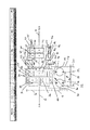
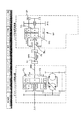
図1は、VATの第1実施形態を概略的に示す。無段変速機(以下、ときに「変速機」と略称する)は、動作にあたり車両(図示せず)のエンジンに連結する変速機の入力軸2と、車両のホイールのような負荷(図示せず)に連結する変速機の出力軸4とを備える。入力軸2は、第1衛星ギア8と噛合する入力ギア6を担持し、この第1衛星ギア8は、入力軸2に平行なバリエータ入力軸10に担持する。このバリエータ入力軸10は、全体的に参照符号12で示したバリエータを駆動し、図示の実施例ではバリエータは油圧式バリエータとする。バリエータ12は、バリエータ入力軸10によって駆動される可変容量形ポンプ14を有する。ポンプ14は、既知タイプの制御素子又は斜板16を有し、また1対の油圧ライン20,22によって油圧モータ18に接続する。この油圧モータ18はバリエータ出力軸24に連結し、このバリエータ出力軸24はバリエータ出力ギア26を担持する。副軸28は、バリエータ軸10,24に平行に配置し、また、バリエータ出力ギア26に噛合する第1副軸ギア30と、及びサミング変速装置(summing transmission)34の第1サンギア36に噛合する第2副軸ギア32とを有する。
FIG. 1 schematically shows a first embodiment of VAT. The continuously variable transmission (hereinafter sometimes abbreviated as “transmission”) includes a
サミング又はデファレンシャル変速装置(summing, or differential, transmission)34は、第1遊星ギア38及び第2遊星ギア48を有し、これら第1及び第2の遊星ギアはそれぞれ第1遊星ギアキャリヤ39及び第2遊星ギアキャリヤ49に回転可能に支持する。第1遊星ギア38は、第1サンギア36及び第1リングギア40に噛合する。第2遊星ギア48は、第2サンギア46及び第2リングギア50に噛合する。第1リングギア40及び第2遊星ギアキャリヤ49を入力軸2に連結し、入力軸2の回転がこれら2つの素子を同様に回転させるようにする。第1遊星ギアキャリヤ39及び第2リングギア50は、第1低速クラッチ52の形態とした第1連結コンポーネントの入力側に連結する。第2サンギア46は、第1中間軸54に対して回転不能に連結し、この第1中間軸54は入力軸2及び出力軸4に同軸状にする。第1中間軸54は第1高速クラッチ56の形態とした第2連結コンポーネントの入力側に連結する。
A summing or
第1低速クラッチ52及び第1高速クラッチ56は、それぞれサミング変速装置34を出力又はレンジ切換変速装置(output, or range, transmission)60に選択的に連結し、これら変速装置34,60は互いに同軸状となるようにする。これらクラッチ52,56の双方は、サミング変速装置34と出力変速装置60との間に画定した連結空間に配置する。上述したように、低速及び高速のクラッチ52,56それぞれにおける入力側をサミング変速装置34の少なくとも1個の素子に連結する。低速及び高速のクラッチ52,56それぞれにおける出力側を第2中間軸58に連結し、この第2中間軸58は、変速機の入力軸2及び出力軸4、並びに第1中間軸54と同軸状になるようにする。出力変速装置60は、第3サンギア62及び第4サンギア72を有し、これら第3及び第4のサンギア双方を第2中間軸58に連結する。第3サンギア62は、第3遊星ギアキャリヤ65に回転可能に支持した第3遊星ギア64に噛合し、またこの第3遊星ギア64は第3リングギア66に噛合する。第4サンギア72は、第4遊星ギアキャリヤ75に回転可能に支持した第4遊星ギア74に噛合し、またこの第4遊星ギア74は第4リングギア76に噛合する。第3遊星ギアキャリヤ65はリバース部材80に連結し、このリバース部材80は、出力軸4における逆回転を生ずるため、摺動カラー82によって選択的に回転しないよう保持することができる。
The first low-
第2中間軸58に選択的に連結するとともに、第1低速クラッチ52及び第1高速クラッチ56は、第2高速クラッチ84の形態とした第3連結コンポーネントの入力側にも選択的に連結する。第2高速クラッチ84は、第1低速クラッチ52及び第1高速クラッチ56とともに連結空間内に配置し、また第3遊星ギアキャリヤ65に連結した出力側を有する。したがって、第2高速クラッチ84が係合するとき、第3サンギア62及び第3遊星ギア64が互いにロックされ、一体となって回転する。
The first
第3及び第4のリングギア66,67は、互いに連結し、また第2低速クラッチ又は制動素子90に連結する。第2低速クラッチ90が係合するとき、第3及び第4のリングギア66,67は回転を阻止される。第4遊星ギアキャリヤ75を出力軸4に連結する。
The third and fourth ring gears 66 and 67 are connected to each other and to the second low speed clutch or
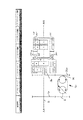
図2は、図1に示す実施形態の変更例であるVATの第2実施形態を概略的に示す。第1実施形態においては、バリエータは、サミング変速装置及び出力変速装置の下方で車両内にパッケージ化することを意図した。この第2実施形態においては、バリエータの位置は、サミング変速装置及び出力変速装置と一列に並ぶよう移動する。この変更は、入力ギア6及び衛星ギア8を入力軸2に沿って移動することに関連し、したがって、入力ギア6及び衛星ギア8がエンジン(図示せず)に一層接近する。このことは空間を自由にし、また変速機の残りの部分に一列となって並ぶ何もない空間内にバリエータ12を移動させることを可能にする。この結果、副軸は排除し、バリエータ出力軸24を、第1サンギア36にバリエータの出力ギア26を介して直結することができる。
FIG. 2 schematically shows a second embodiment of VAT, which is a modification of the embodiment shown in FIG. In the first embodiment, the variator was intended to be packaged in the vehicle below the summing transmission and the output transmission. In the second embodiment, the position of the variator moves so as to line up with the summing transmission and the output transmission. This change is related to moving the
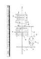
図3は、図1に示す実施形態の他の変更例であるVATの第3実施形態を概略的に示す。図から分かるように、この変更例は、サミング変速装置34と出力変速装置60との間に連結コンポーネント100を追加的に導入している。このバリエータの連結コンポーネント100は好適にはクラッチであり、このクラッチは、言及を簡単にするためバリエータクラッチと称する。バリエータクラッチ100は、第1中間ギア102によってバリエータ出力ギア26に連結した入力側を有し、この第1中間ギア102は、出力ギア26と同軸状であり、同一のバリエータ出力軸24に連結する。第2中間ギア104は第1中間ギア102に噛合する。この第2中間ギア104は、バリエータクラッチ100の入力側に連結する。バリエータクラッチ100の出力側は第2中間軸58に連結する。したがって、この実施形態において、バリエータモータ18は、バリエータクラッチ100を介して出力変速装置60及び出力軸4に直結することができ、また第1低速クラッチ52及び第1高速クラッチ56がともに離脱するときサミング変速装置34をバイパスすることができる。
FIG. 3 schematically shows a third embodiment of VAT, which is another modification of the embodiment shown in FIG. As can be seen, this modification additionally introduces a connecting
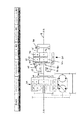
図4は、図3に示す第3実施形態の他の変更例であるVATの第4実施形態を概略的に示し、また図2に示したのと同様に、バリエータ12の再配置に関する。第2実施形態と同様に、この第4実施形態において、バリエータの位置は、サミング変速装置34及び出力変速装置60に一列に並ぶよう移動する。この変更例は、入力ギア6及び衛星ギア8を入力軸2に沿って移動することに関連し、したがって、入力ギア6及び衛星ギア8がエンジン(図示せず)に一層接近する。このことは空間を自由にし、また変速機の残りの部分に一列となって並ぶ何もない空間内にバリエータ12を移動させることを可能にする。この結果、副軸は排除し、バリエータ出力軸24を、第1サンギア36にバリエータの出力ギア26を介して直結することができる。バリエータ出力軸24は、第3実施形態と同一構成を使用してバリエータクラッチ100の入力側に連結したままとする。
FIG. 4 schematically shows a fourth embodiment of the VAT, which is another modification of the third embodiment shown in FIG. 3, and relates to the rearrangement of the variator 12 as shown in FIG. Similar to the second embodiment, in the fourth embodiment, the position of the variator moves so as to line up with the summing
図5は、図1に示すVATの他の変更例であるVATの第5実施形態を概略的に示す。この実施形態において、第2高速クラッチ84及び第2低速クラッチ90並びにリバース部材80は出力変速装置60の周りに再配置し、これは、軸線方向及び半径方向の双方に関してより一層コンパクトな変速機にすることを狙ってのものである。
FIG. 5 schematically shows a fifth embodiment of VAT, which is another modification of the VAT shown in FIG. In this embodiment, the second
第1実施形態と同様に、第2中間軸58は、第3サンギア62及び第4サンギア72に、また第2高速クラッチ84の入力側に連結する。しかし、第2高速クラッチ84は、このとき、サミング変速装置34と出力変速装置60との間ではなく、出力変速装置60の出力側に配置する。第2高速クラッチ84の出力側は、このとき、先の実施形態と同様に、それ自体出力軸4に連結した第4遊星ギアキャリヤ75に連結する。第1実施形態と同様に、第3及び第4のリングギア66,76は互いに連結し、また第2低速クラッチ90にも連結する。しかし、第2低速クラッチは、このとき、サミング変速装置34と出力変速装置60との間に配置する。先の実施形態のように、リバース部材80は第3遊星ギアキャリヤ65に連結する。しかし、リバース部材80及びその摺動カラー82は、このとき、第2低速クラッチ90の半径方向内側に配置し、第3遊星ギアキャリヤ65及びリバース部材を互いに連結し、この連結は第2中間軸58と同軸状の管状軸110によって行う。
Similar to the first embodiment, the second
図6は、図5に示す実施形態の変更例であるVATの第6実施形態を概略的に示す。図で分かるように、この変更例は、図3に示す第3実施形態と同様に、サミング変速装置34と出力変速装置60との間にバリエータクラッチ100を導入している。第3実施形態と同様に、バリエータクラッチ100はバリエータ出力ギア26に連結した入力側を有する。バリエータクラッチ100は、出力ギア26と同軸状であり、同一のバリエータ出力軸24に連結する第1中間ギア102、及び第1中間ギア102に噛合する第2中間ギア104によってバリエータ出力ギア26に連結する。この第2中間ギア104は、バリエータクラッチ100の入力側に連結する。バリエータクラッチ100の出力側は第2中間軸58に連結する。したがって、この実施形態において、第3実施形態と同様に、バリエータモータ18は、バリエータクラッチ100を介して出力変速装置60及び出力軸4に直結することができ、また第1低速クラッチ52及び第1高速クラッチ56がともに離脱するときサミング変速装置34をバイパスすることができる。
FIG. 6 schematically shows a sixth embodiment of VAT, which is a modification of the embodiment shown in FIG. As can be seen in the figure, in this modified example, the
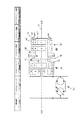
図7は、図1に示す第1実施形態の他の変更例であるVATの第7実施形態を概略的に示す。この変更した実施形態において、変速機は、変速機を軸線方向により一層コンパクトにするよう、サミング変速装置34及び出力変速装置60の上方にパッケージ化したオフセット入力軸202を採用する。この入力軸202は、エンジン(図示せず)に連結し、またエンジンに近接する基端側に第1入力ギア206を有する。第2入力ギア207を入力軸202のエンジンから遠い側の末端部に配置する。衛星ギア208は、第2入力ギア207に噛合させ、また入力軸202に平行に配置したバリエータ入力軸210に担持する。バリエータ入力軸210は、図1に示したのと同一構成を有する油圧式のバリエータ12を駆動する。バリエータ12のモータ18は、バリエータ出力ギア226を担持するバリエータ出力軸224に連結する。バリエータ出力ギア226はサミング変速装置34の第1サンギア36に噛合する。
FIG. 7 schematically shows a seventh embodiment of the VAT, which is another modification of the first embodiment shown in FIG. In this modified embodiment, the transmission employs an offset
第1入力ギア206は、駆動軸228に対して回転不能に支持した駆動ギア227に噛合する。駆動軸228は、出力軸4に対して同軸状にし、また入力軸202に対して平行にする。駆動軸228は、第1実施形態における入力軸2と同様にして、サミング変速装置34の第1リングギア40及び第2遊星ギアキャリヤ49に連結する。サミング変速装置34及び出力変速装置60の残りの部分、種々のクラッチ及びリバース部材は、図1につき説明したのと同一にする。
The
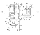
図8は、図5に示す第5実施形態の変速機の変更例であるVATの第8実施形態を概略的に示す。この第8実施形態において、VATは、軸線方向ができるだけコンパクトになるよう変更してある。このことは、この実施形態において、バリエータ、サミング変速装置、出力変速装置及び出力軸が互いに平行となるようパッケージ化することによって達成する。入力軸2、サミング変速装置34及びバリエータ12の構成は、図5(並びに図1及び3)に示したのとほぼ同一であり、ここではそれ以上説明しない。この変更した実施形態において、第2中間軸58は、先の実施形態よりも相当短く、また遠い側の端部、すなわち、サミング変速装置34及び第1低速クラッチ52及び第1高速クラッチ56から離れる端部に取り付けた第1中間ギア302を有する。第2中間ギア304は、第1中間ギア302に噛合させ、また第3中間軸306に連結する。この第3中間軸306は、入力軸2、並びに第1中間軸54及び第2中間軸58に対して平行に延び、エンジン(図示せず)に向かって逆行する。出力変速装置60は第3中間軸306上に配置し、この第3中間軸306は、図5における第2中間軸と同様にして、第3サンギア62及び第4サンギア72、並びに第2高速クラッチ84の入力側に連結する。
FIG. 8 schematically shows an eighth embodiment of the VAT, which is a modification of the transmission of the fifth embodiment shown in FIG. In the eighth embodiment, the VAT is changed so that the axial direction is as compact as possible. This is achieved in this embodiment by packaging the variator, summing transmission, output transmission and output shaft so that they are parallel to each other. The configurations of the
第4遊星ギアキャリヤ75及び第2高速クラッチ84の出力側を第4中間軸308に連結する。第4中間軸308の端部には第3中間ギア310を固着する。第3中間ギア310は、入力軸2及び種々の中間軸54,58,306に平行な出力軸4に連結した出力ギア312に噛合させる。図示の実施形態において、駆動力は、車両(図示せず)のフロント及びリアに、1対の自在継手318,320により出力軸4に連結したフロント駆動軸314及びリア駆動軸316を介して向かわせる。
The output sides of the fourth
図9は、VATの第9実施形態を概略的に示し、この場合、VATは、例えば、キャタピラー725Cのような、関節連結式のオフ・ハイウェイトラック内にパッケージ化する。第9実施形態は、図5に示す第5実施形態の変更例である。この実施形態を関節連結式トラックに採用するとき、第2中間軸58は、3つの同軸状の軸部分58A〜58Cに分割する。第1軸部分58Aは、第1低速クラッチ52及び第1高速クラッチ56の出力側を、第1自在継手57を介して第2軸部分58Bに連結する。この第2軸部分58Bの第2端部は、第2自在継手59を介して第3軸部分58Cに連結する。出力変速装置60の第3サンギア62及び第4サンギア72は、第2高速クラッチ84の入力側として、第3軸部分58Cに配置する。
FIG. 9 schematically illustrates a ninth embodiment of a VAT, where the VAT is packaged in an articulated off-highway truck, such as a caterpillar 725C. The ninth embodiment is a modification of the fifth embodiment shown in FIG. When this embodiment is employed in an articulated truck, the second
第2高速クラッチ84の出力側は、第5実施形態におけるのと同様に、第4遊星ギアキャリヤ75に連結する。しかし、第9実施形態は、第2高速クラッチ84の出力側における出力軸を出力ギア404に置換することによってさらに変更する。関節連結式トラックにおいて、この出力ギア404は、トラックのフロント及びリアのホイールに駆動力を供給するロック可能な差動装置(図示せず)に連結する。
The output side of the second
VATの第10実施形態を図10に概略的に示す。この第10実施形態は、図2に示す第2実施形態の変更例である。第10実施形態におけるバリエータ12、サミング変速装置34、種々のクラッチ52,56,84,90及びリバース部材80の構成は、第2実施形態のものと同一である。しかし、この第10実施形態においては、出力変速装置60′内のギア構成は変更している。この実施形態において、第3リングギア66′は、第4リングギア76′に連結する代わりに、第4遊星ギアキャリヤ75′及び出力軸4に連結する。第4リングギア76′のみを第2低速クラッチ90に連結する。
A tenth embodiment of the VAT is schematically illustrated in FIG. The tenth embodiment is a modification of the second embodiment shown in FIG. The configurations of the
図1〜10に示すバリエータ支援変速機の各実施形態によれば、4つの前進モード及び2つの後進モードを有する無段変速機を提供する。第3、第4及び第6実施形態は、さらに、バリエータクラッチ構成に付加して、以下に詳細に説明する速度ゼロ及び寸動モードを有する。 According to each embodiment of the variator-assisted transmission shown in FIGS. 1 to 10, a continuously variable transmission having four forward modes and two reverse modes is provided. The third, fourth and sixth embodiments further have a zero speed and inching mode which will be described in detail below in addition to the variator clutch configuration.
種々の前進及び後進の変速モードに関連して、図示の各実施形態は、バリエータクラッチを採用する実施形態を含めて、ほぼ同じように動作する。したがって、図1に示す第1実施形態の動作のみを詳細に説明する。しかし、この動作方法は本明細書に記載の任意な他の実施形態にも適用することができる。変速機の動作方法はすべての実施形態にわたり同一であるが、第2高速クラッチが係合するときに動力を出力側に供給する様態は、当該実施形態が、第2高速クラッチをサミング変速装置と出力変速装置との間に配置している(図1〜4及び図7に示す実施形態のように)変速機か否か、第2高速クラッチを出力変速装置60の出力側に配置する(図5,6,8及び9に示す実施形態のように)か否か、すなわち、実際出力変速装置のギアをどのように互いに連結する(図10参照)か否かに左右される。
In connection with the various forward and reverse shift modes, the illustrated embodiments operate in substantially the same manner, including embodiments that employ a variator clutch. Therefore, only the operation of the first embodiment shown in FIG. 1 will be described in detail. However, this method of operation can also be applied to any other embodiment described herein. Although the operation method of the transmission is the same throughout all the embodiments, the embodiment in which the power is supplied to the output side when the second high speed clutch is engaged is the same as that of the second high speed clutch and the summing transmission. The second high speed clutch is arranged on the output side of the
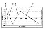
図11は、バリエータモータ18の速度が符号1F〜4Fで示す4つの前進モードにわたりどのように変動するか、及びそれら変動が変速機を使用する車両の地上走行速度に関連するかを示す。当然のことながら、車両の実際の地上走行速度は多数の要因に依存し、とくに、サミング変速装置及び出力変速装置に使用される遊星ギアの特定ギア比、及び変速機入力軸におけるエンジンからの入力速度によって左右されることを認識されたい。このグラフ及びこの説明における特定値は、したがって、単なる例として捉えるべきであり、また本発明の範囲を何ら限定するものではない。
FIG. 11 shows how the speed of the
図1及び11につき説明すると、第1前進変速機モード1Fをとるとき、バリエータポンプ14の斜板16が最大負変位量に調整され、これによりバリエータモータ18が最大負速度を生ずる。この実施例におけるエンジンからの変速機入力速度は約1600rpmであり、この状態において、バリエータモータ18に連結した第1サンギア36は約−1600rpmで回転する。第1低速クラッチ52及び第2低速クラッチ90は双方とも係合する。したがって、動力は、入力軸2から出力変速装置60まで、サミング変速装置34における第1リングギア40、第1遊星ギアキャリヤ39及び第2リングギア50、並びに第1低速クラッチ52を経由して供給される。第1低速クラッチ52からは、動力は、出力変速装置60における第2中間軸58、第4サンギア72及び第4遊星ギアキャリヤ75を経由して出力軸4に供給される。
Referring to FIGS. 1 and 11, when the first
エンジン入力速度がほぼ一定な状態で、第1変速機モード1Fによる車両の加速は、バリエータ12の制御によって達成される。図11から分かるように、バリエータの負変位量及び関連速度はゼロに向かい、またゼロを超えて正の変位量及び関連速度になるとき、車両の地上走行速度が増加する。この速度変化は、バリエータ12によって影響される第1サンギア36の回転方向及び回転速度に基づく。第1リングギア40が入力軸2に直結されるとき、第1リングギア40の最大速度は、バリエータがその最大正変位量及び速度になるときの第1サンギア36の回転速度と同一の約1600rpmとなる。
In the state where the engine input speed is substantially constant, the acceleration of the vehicle in the
車両速度がさらに上昇するためには、変速機は第1前進モード1Fから第2前進モード2Fにシフトしなければならない。このことには、第1低速クラッチ52を離脱させ、また第1高速クラッチ56を係合させるとともに、第2低速クラッチ90が係合したままで出力変速装置60におけるリングギア66,76を制動していることを伴う。これらの変化が実施されると、動力は、入力軸2から第1遊星ギアキャリヤ49、第2サンギア46、及び第1中間軸54を介して、第1高速クラッチ56に供給される。この第1高速クラッチ56から、動力は、さらに、第2中間軸58、第4サンギア72及び第4遊星ギアキャリヤ75を介して出力軸4に供給される。
In order to further increase the vehicle speed, the transmission must shift from the first
第2前進モード2Fにおける車両の加速は、やはりバリエータ12の制御によって達成される。再度図11につき説明すると、バリエータの正変位量及び関連速度はゼロに向かい、またゼロを越えて負変位量及び関連速度になるとき、車両の地上走行速度は、第2サンギア46よりも第1サンギア36の回転速度及び回転方向における変化に起因して一層上昇する。
The acceleration of the vehicle in the second
さらに、車両速度における上昇は、第3前進モード3F及び第4前進モード4Fに進行することによって達成される。第2前進モード2Fから第3前進モード3Fに進行するため、第1高速クラッチ56及び第2低速クラッチ90が離脱し、また第1低速クラッチ及び第2高速クラッチ84が係合する。この結果、動力は、入力軸2から第1リングギア40、第1遊星ギアキャリヤ39及び第2リングギア50を介して第1低速クラッチ52に供給される。図1〜4及び図7に示す実施形態において、第2高速クラッチ84が係合した状態で、第2中間軸58、それに関連するサンギア62,72及び第3遊星ギアキャリヤ65が一体となって回転する。この結果、第2前進モード2Fよりも第3前進モード3Fにおける第2中間軸58の回転速度に段変化減少を生ずる。このとき第2低速クラッチ90が離脱した状態で、第3リングギア66及び第4リングギア76が出力変速装置60の残りのコンポーネントに対して回転することができ、この結果、動力は、第4遊星ギアキャリヤ75を介して出力軸4に供給される。
Furthermore, the increase in the vehicle speed is achieved by proceeding to the third
図5,6,8及び9に示す実施形態において、第2高速クラッチ84が係合するとき、動力を出力軸4に供給するため、中間軸58、サンギア62,72及び第4遊星ギアキャリヤ75が一体として回転する。図10の実施形態において、第2高速クラッチ84が係合するとき、第3サンギア62及び第3遊星ギアキャリヤ65が一体として回転し、また動力は第3リングギア66′及び第4遊星ギアキャリヤ75′を介して出力軸4に供給される。
In the embodiment shown in FIGS. 5, 6, 8 and 9, the
再度図11につき説明すると、バリエータ変位量が−1600rpmの最大負変位量及び回転速度からゼロを通過して増加するとき、地上走行速度は第3前進モード3Fにおいて上昇し、最終的に第1サンギアが再び1600rpmの最大速度で回転するようになる。
Referring again to FIG. 11, when the variator displacement increases from zero to the maximum negative displacement of -1600 rpm and the rotational speed, the ground traveling speed increases in the third
第4前進モード4Fは第3前進モード3Fから進行し、この進行は、第2高速クラッチ84を係合させたまま、第1低速クラッチ52を離脱させ、また第1高速クラッチ56を係合させることによって行われる。これにより、動力は、入力軸2から第2遊星ギアキャリヤ49、第2サンギア46及び第1中間軸54を介して第1高速クラッチ56に供給される。第2高速クラッチ84が係合するとき、動力は、第3前進モード3F、及び図1〜4及び図7、図5,6,8及び図9並びに図10に示した実施例グループに関して説明したのと同様にして出力軸4に供給される。
The fourth
第4前進モード4Fにおける車両の加速は、やはりバリエータ12の制御によって達成される。再度図11につき説明すると、バリエータの正変位量及び関連速度はゼロに向かい、またゼロを越えて負変位量及び関連速度になるとき、車両の地上走行速度は、第2サンギア46よりも第1サンギア36の回転速度及び回転方向における変化に起因して一層上昇する。
The acceleration of the vehicle in the fourth
上述の実施形態の変速機は2つの後進変速機モード1R及び2Rを有する。初期後進変速機モード1Rで動作するためには、変速機における第1低速クラッチ52を除くすべてのクラッチを離脱させる。これと同時に、摺動カラー82をリバース部材80に接触させ、この結果、リバース部材及び第3遊星ギアキャリヤ65をカラー82によって回転しないよう保持する。これにより、動力は、入力軸2から第1リングギア40、第1遊星ギアキャリヤ39及び第2リングギア50を介して第1低速クラッチ52に供給される。
The transmission of the above-described embodiment has two reverse transmission modes 1R and 2R. In order to operate in the initial reverse transmission mode 1R, all the clutches except the first
第2中間軸58及びこれに関連するサンギア62,72が、第1低速クラッチ52の係合に起因して第1方向に回転する。第3遊星ギアキャリヤ65が回転しないよう保持されていることに起因して、第3及び第4のリングギア66,76がサンギア62,72の回転とは逆方向に回転する。このことは、第4遊星ギアキャリヤ75及び出力軸4も逆方向に回転し、したがって、車両が後進することを意味する。
The second
より速く後進する地上走行速度が必要な場合、変速機は第1後進モード1Rから第2後進モード2Rに移行することができる。そのようにするため、第1低速クラッチ52を離脱させ、また第1高速クラッチ56を係合させ、このとき摺動カラー82は係合させて、リバース部材80及び第3遊星ギアキャリヤ65を回転しないよう保持した状態を継続する。このモードにおいて、動力は、第2遊星ギアキャリヤ49、第2サンギア46及び第1中間軸54を介して第1高速クラッチ56に供給される。動力は、第1後進モード1Rにつき説明したのと同様に、出力変速装置を介して出力軸4に供給される。
If a faster ground speed is required, the transmission can transition from the first reverse mode 1R to the second reverse mode 2R. To do so, the first low-
後進モード1R、2Rのいずれにおいても、車両の地上走行速度は、やはり前進モード1F〜4Fにつき説明したのと同様に、バリエータ12によって第1サンギア36の回転速度及び回転方向を調整することで調整することができる。
In either of the reverse modes 1R and 2R, the ground traveling speed of the vehicle is adjusted by adjusting the rotational speed and the rotational direction of the
本明細書に記載したVATの多数の実施形態は、ゼロ速度出力及び徐行/寸動機能を生ずることもできる。これらは、油圧式バリエータクラッチ100を採用する図3,4及び6に示す第3、第4及び第6実施形態である。すでに上述したように、これら実施形態によれば、バリエータ12は、サミング変速装置34をバイパスし、中間軸58、サンギア62,72及び第4遊星ギアキャリヤ75を介して出力軸4に直結することができる。この機能を容易にするため、第1低速クラッチ52及び第1高速クラッチ56を第2高速クラッチ84とともに離脱させる。第2低速クラッチ90及びバリエータクラッチ100を係合させる。このとき、動力は、バリエータモータ18から、第1及び第2の中間ギア102,104、バリエータクラッチ100、中間軸58、第4サンギア72及び第4遊星ギアキャリヤ75を介して直接出力軸4に供給される。可変容量形ポンプ14の斜板16を調整することにより、バリエータモータ18は中間軸58の回転速度、及びひいては出力軸4の回転速度を制御することができる。したがって、このようなVATを採用する車両は、いかなるクリープもなく休止することができる、又はバリエータ12の制御の下に極めて低速で寸動又は徐行することができる。副軸がバリエータ出力ギア26と第1サンギア36との間に存在する図3及び6に示す実施形態において、変速機をゼロ速度又は徐行モードから第1前進モード1Fに切り換えるのは、単にバリエータクラッチ100を離脱させ、また第1低速クラッチ52を係合させることだけで済む。しかし、副軸が存在しない図4に示す実施形態においては、徐行モードから第1前進モード1Fに切り換えるには、バリエータクラッチ100を離脱させ、即座にバリエータモータ18及びバリエータ出力ギア26の回転方向をバリエータポンプ14の斜板16を介して逆転させ、次いで第1低速クラッチ52を係合させることを行う。
Numerous embodiments of the VAT described herein can also provide zero speed output and slow / inch function. These are the third, fourth and sixth embodiments shown in FIGS. 3, 4 and 6 which employ a
本発明による変速機を組み込む車両を始動させるには、第1低速クラッチ52(又は存在する他の任意なクラッチ)を係合させ、またクラッチ入力及び出力素子が互いに所定範囲内の速度で回転するようになるまで、制御した滑りを生ずるようにする。次にクラッチを変速機のために完全に係合させ、第1前進モード1F又は第1後進モード1Rのいずれかに進行させる。
To start a vehicle incorporating a transmission according to the invention, the first low speed clutch 52 (or any other clutch present) is engaged and the clutch input and output elements rotate at a speed within a predetermined range of each other. A controlled slip is produced until The clutch is then fully engaged for the transmission and advanced to either the first
連結コンポーネントの大部分、及び少なくとも第1及び第2の連結コンポーネントのデファレンシャル変速装置とレンジ切換変速装置との間における連結空間内への配置によれば、本発明バリエータ支援変速機を、このタイプの既知変速機よりも一層コンパクトにすることができる。一層コンパクトになることは、変速機を既知変速機よりも一層軽量かつ安価にすることができることを意味し、この結果、トラック型トラクタ等のような大規模用途以外の、オンハイウェイトラック及びバスのような比較的小規模な用途にも利用できることになる。 According to the arrangement of the majority of the coupling components and at least the first and second coupling components in the coupling space between the differential transmission and the range switching transmission, the variator-assisted transmission of the present invention is of this type. It can be made more compact than known transmissions. Being more compact means that the transmission can be made lighter and cheaper than known transmissions, resulting in on-highway trucks and buses other than large-scale applications such as truck-type tractors. It can also be used for such relatively small applications.
随意的バリエータ連結コンポーネントを含む実施形態において、本発明は、レンジ切換変速装置を介してバリエータと出力軸との間の直結を行う。それら実施形態は、したがって、バリエータによって制御するゼロ速度及び寸動/徐行モードを有し、またこのようなモードが望ましい車両において実装することができる。 In an embodiment that includes an optional variator coupling component, the present invention provides a direct connection between the variator and the output shaft via a range switching transmission. The embodiments thus have zero speed and jogging / slow mode controlled by the variator and can be implemented in vehicles where such mode is desirable.
各好適実施形態に使用したバリエータは油圧式バリエータであるが、本発明はこのようなバリエータの使用に限定するものではない。例えば、本発明のVATは、代案として、電気的又は機械的なバリエータを使用することができる。 Although the variator used in each preferred embodiment is a hydraulic variator, the present invention is not limited to the use of such a variator. For example, the VAT of the present invention can alternatively use an electrical or mechanical variator.
変速機の好適な実施形態は、第4リングギアを第3リングギアに連結する、又は第3リングギアを第4遊星ギアキャリヤに連結する出力変速装置を備える。しかし、出力変速装置は、それに代わって第4リングギアを第3遊星ギアキャリヤに連結するよう構成することができる。 A preferred embodiment of the transmission includes an output transmission that connects the fourth ring gear to the third ring gear or connects the third ring gear to the fourth planetary gear carrier. However, the output transmission can alternatively be configured to connect the fourth ring gear to the third planetary gear carrier.
好適な実施形態に利用される連結コンポーネントはすべてクラッチであるが、それに代わって1つ又は複数の連結コンポーネントを摺動カラーとすることができる。さらに、クラッチを使用する場合、クラッチにはシンクロナイザ(同期装置)を設けることができる。 The coupling components utilized in the preferred embodiment are all clutches, but alternatively one or more coupling components can be a sliding collar. Furthermore, when using a clutch, a synchronizer (synchronizer) can be provided in the clutch.
これら及び他の変更及び改変を、本発明の範囲を逸脱することなく、組み込むことができる。 These and other changes and modifications can be incorporated without departing from the scope of the invention.
2 入力軸
4 出力軸
6 入力ギア
8 第1衛星ギア
10 (バリエータ)入力軸
12 バリエータ
14 可変容量形ポンプ
16 斜板
18 油圧モータ(バリエータモータ)
20 油圧ライン
22 油圧ライン
24 (バリエータ)出力軸
26 (バリエータ)出力ギア
28 副軸
30 第1副軸ギア
32 第2副軸ギア
34 サミング変速装置
36 第1サンギア
38 第1遊星ギア
39 第1遊星ギアキャリヤ
40 第1リングギア
46 第2サンギア
48 第2遊星ギア
49 第2遊星ギアキャリヤ
50 第2リングギア
52 第1低速クラッチ
54 第1中間軸
56 第1高速クラッチ
57 第1自在継手
58 第2中間軸
58A (中間軸の)軸部分
58B (中間軸の)軸部分
58C (中間軸の)軸部分
59 第2自在継手
60 出力又はレンジ切換変速装置
60′ 出力又はレンジ切換変速装置
62 第3サンギア
64 第3遊星ギア
65 第3遊星ギアキャリヤ
66 第3リングギア
66′ 第3リングギア
67 第4リングギア
72 第4サンギア
74 第4遊星ギア
75 第4遊星ギアキャリヤ
75′ 第4遊星ギアキャリヤ
76 第4リングギア
76′ 第4リングギア
80 リバース部材
82 摺動カラー
84 第2高速クラッチ
90 第2低速クラッチ又は制動素子
100連結コンポーネント
102 第1中間ギア
104 第2中間ギア
110 管状軸
202 入力軸
206 第1入力ギア
207 第2入力ギア
208 衛星ギア
210 バリエータ入力軸
224 バリエータ出力軸
226 バリエータ出力ギア
227 駆動ギア
228 駆動軸
302 第1中間ギア
304 第2中間ギア
306 第3中間軸
308 第4中間軸
310 第3中間ギア
312 出力ギア
314 フロント駆動軸
316 リア駆動軸
318 自在継手
320 自在継手
404 出力ギア
2
DESCRIPTION OF SYMBOLS 20 Hydraulic line 22 Hydraulic line 24 (Variator) output shaft 26 (Variator) output gear 28 Sub shaft 30 First counter shaft gear 32 Second counter shaft gear 34 Summing transmission 36 First sun gear 38 First planetary gear 39 First planet Gear carrier 40 First ring gear 46 Second sun gear 48 Second planetary gear 49 Second planetary gear carrier 50 Second ring gear 52 First low speed clutch 54 First intermediate shaft 56 First high speed clutch 57 First universal joint 58 Second Intermediate shaft 58A (Intermediate shaft) shaft portion 58B (Intermediate shaft) shaft portion 58C (Intermediate shaft) shaft portion 59 Second universal joint 60 Output or range switching transmission 60 'Output or range switching transmission 62 Third sun gear 64 Third planetary gear 65 Third planetary gear carrier 66 Third ring gear 66 ′ Third ring gear 67 Fourth Ng gear 72 fourth sun gear 74 fourth planetary gear 75 fourth planetary gear carrier 75 ′ fourth planetary gear carrier 76 fourth ring gear 76 ′ fourth ring gear 80 reverse member 82 sliding collar 84 second high speed clutch 90 second low speed Clutch or braking element 100 connecting component 102 first intermediate gear 104 second intermediate gear 110 tubular shaft 202 input shaft 206 first input gear 207 second input gear 208 satellite gear 210 variator input shaft 224 variator output shaft 226 variator output gear 227 drive Gear 228 Drive shaft 302 First intermediate gear 304 Second intermediate gear 306 Third intermediate shaft 308 Fourth intermediate shaft 310 Third intermediate gear 312 Output gear 314 Front drive shaft 316 Rear drive shaft 318 Universal joint 320 Universal joint 404 Output gear
Claims (25)
エンジンによって駆動可能な入力軸と、
負荷に連結可能な出力軸と、
前記入力軸に連結した入力側、及び出力側を有し、前記入力側と前記出力側との間における速度伝達比を変化させるよう調整可能であるバリエータと、
前記入力軸に連結した第1デファレンシャル入力素子、前記バリエータの前記出力側に連結した第2デファレンシャル入力素子、並びに第1デファレンシャル出力素子及び第2デファレンシャル出力素子を有するデファレンシャル変速装置と、
第1レンジ入力素子、及び前記出力軸に連結した少なくとも1個のレンジ出力素子を有するレンジ切換変速装置と、
第1デファレンシャル出力素子を選択的に第1レンジ入力素子に連結する第1連結コンポーネントと、
第2デファレンシャル出力素子を選択的に第1レンジ入力素子に連結する第2連結コンポーネントと、
を備え、また
前記第1連結コンポーネント及び前記第2連結コンポーネントは、前記デファレンシャル変速装置と前記レンジ切換変速装置との間に画定した連結空間内に配置する、無段変速機。 A continuously variable transmission,
An input shaft that can be driven by an engine;
An output shaft connectable to a load;
A variator that has an input side connected to the input shaft, and an output side, and is adjustable to change a speed transmission ratio between the input side and the output side;
A differential transmission device having a first differential input element coupled to the input shaft, a second differential input element coupled to the output side of the variator, and a first differential output element and a second differential output element;
A range switching transmission having a first range input element and at least one range output element coupled to the output shaft;
A first coupling component that selectively couples the first differential output element to the first range input element;
A second coupling component that selectively couples the second differential output element to the first range input element;
In addition, the first connection component and the second connection component are arranged in a connection space defined between the differential transmission device and the range switching transmission device.
第1サンギア、第1遊星ギアキャリヤに回転可能に支持した第1遊星ギア、及び第1リングギアを含む第2遊星ギアセットと、並びに
第2サンギア、第2遊星ギアキャリヤに回転可能に支持した第2遊星ギア、及び第2リングギアを含む第2遊星ギアセットと、
を有し、
前記第1デファレンシャル入力素子を前記第2遊星ギアキャリヤ及び前記第1リングギアに連結し、前記第2デファレンシャル入力素子を前記第1サンギアに連結し、前記第1デファレンシャル出力素子を前記第1遊星ギアキャリヤ及び前記第2リングギアに連結し、また前記第2デファレンシャル出力素子を前記第2サンギアに連結する、無段変速機。 2. The continuously variable transmission according to claim 1, wherein the differential transmission device includes:
A first planetary gear set including a first sun gear, a first planetary gear rotatably supported on a first planetary gear carrier, and a first ring gear; and a second sun gear and rotatably supported on a second planetary gear carrier. A second planetary gear set including a second planetary gear and a second ring gear;
Have
The first differential input element is connected to the second planetary gear carrier and the first ring gear, the second differential input element is connected to the first sun gear, and the first differential output element is connected to the first planetary gear. A continuously variable transmission that is connected to a carrier and the second ring gear and that connects the second differential output element to the second sun gear.
第3サンギア、第3遊星ギアキャリヤに回転可能に支持した第3遊星ギア、及び第3リングギアを含む第3遊星ギアセットと、
第4サンギア、第4遊星ギアキャリヤに回転可能に支持した第4遊星ギア、及び第4リングギアを含む第4遊星ギアセットと、並びに
少なくとも第4リングギアを選択的に回転不能に保持する制動素子と
を有し、
前記第3及び第4のサンギアを前記第1レンジ入力素子に連結し、また前記第4遊星ギアキャリヤを前記少なくとも1個のレンジ出力素子に連結する、無段変速機。 The continuously variable transmission according to claim 3, wherein the range switching transmission device further includes:
A third planetary gear set including a third sun gear, a third planetary gear rotatably supported on a third planetary gear carrier, and a third ring gear;
A fourth planetary gear set including a fourth sun gear, a fourth planetary gear rotatably supported by a fourth planetary gear carrier, and a fourth ring gear; and a brake for selectively holding at least the fourth ring gear non-rotatably Having an element,
A continuously variable transmission, wherein the third and fourth sun gears are coupled to the first range input element, and the fourth planetary gear carrier is coupled to the at least one range output element.
第3サンギア、第3遊星ギアキャリヤに回転可能に支持した第3遊星ギア、及び第3リングギアを含む第3遊星ギアセットと、
第4サンギア、第4遊星ギアキャリヤに回転可能に支持した第4遊星ギア、及び第4リングギアを含む第4遊星ギアセットと、並びに
少なくとも第4リングギアを選択的に回転不能に保持する制動素子と
を有し、
前記第3及び第4のサンギアを前記第1レンジ入力素子に連結し、また前記第4遊星ギアキャリヤを前記少なくとも1個のレンジ出力素子に連結する、無段変速機。 The continuously variable transmission according to claim 8 or 9, wherein the range switching transmission device further includes:
A third planetary gear set including a third sun gear, a third planetary gear rotatably supported on a third planetary gear carrier, and a third ring gear;
A fourth planetary gear set including a fourth sun gear, a fourth planetary gear rotatably supported by a fourth planetary gear carrier, and a fourth ring gear; and a brake for selectively holding at least the fourth ring gear non-rotatably Having an element,
A continuously variable transmission, wherein the third and fourth sun gears are coupled to the first range input element, and the fourth planetary gear carrier is coupled to the at least one range output element.
前記第1連結コンポーネント及び前記第2連結コンポーネントのうち一方を動作させて、前記第1デファレンシャル出力素子又は前記第2デファレンシャル出力素子を前記第1レンジ入力素子に連結するステップと、
前記バリエータの前記入力側と前記出力側との間における速度伝達比を変化させるよう前記バリエータを調整するステップと、
を有する、方法。 A method of operating the continuously variable transmission according to any one of claims 1 to 20,
Operating one of the first connected component and the second connected component to connect the first differential output element or the second differential output element to the first range input element;
Adjusting the variator to change a speed transmission ratio between the input side and the output side of the variator;
Having a method.
前記第1及び第2の連結コンポーネントを離脱させるステップと、
前記バリエータの前記出力側を前記第1レンジ入力素子に直結するよう前記バリエータ連結コンポーネントを動作させるステップと、及び
前記バリエータの前記入力側と前記出力側との間の速度伝達比を変化させるよう前記バリエータを調整するステップと、
を有する、方法。 25. The method according to any one of claims 22 to 24, further comprising:
Detaching the first and second connecting components;
Operating the variator coupling component to directly connect the output side of the variator to the first range input element; and changing the speed transmission ratio between the input side and the output side of the variator. Adjusting the variator,
Having a method.
Applications Claiming Priority (3)
| Application Number | Priority Date | Filing Date | Title |
|---|---|---|---|
| EP14172319.7 | 2014-06-13 | ||
| EP14172319.7A EP2955418B1 (en) | 2014-06-13 | 2014-06-13 | A variator-assisted transmission |
| PCT/US2015/035539 WO2015191992A1 (en) | 2014-06-13 | 2015-06-12 | A variator-assisted transmission |
Publications (2)
| Publication Number | Publication Date |
|---|---|
| JP2017519951A true JP2017519951A (en) | 2017-07-20 |
| JP6659070B2 JP6659070B2 (en) | 2020-03-04 |
Family
ID=50933069
Family Applications (1)
| Application Number | Title | Priority Date | Filing Date |
|---|---|---|---|
| JP2016569792A Active JP6659070B2 (en) | 2014-06-13 | 2015-06-12 | Variator assisted transmission |
Country Status (5)
| Country | Link |
|---|---|
| US (1) | US10591038B2 (en) |
| EP (2) | EP2955418B1 (en) |
| JP (1) | JP6659070B2 (en) |
| CN (1) | CN106461032B (en) |
| WO (1) | WO2015191992A1 (en) |
Families Citing this family (7)
| Publication number | Priority date | Publication date | Assignee | Title |
|---|---|---|---|---|
| US10077828B2 (en) | 2016-04-18 | 2018-09-18 | Caterpillar Inc. | Powertrain system for machine and method of operating same |
| US10125848B2 (en) * | 2016-07-19 | 2018-11-13 | Deere & Company | Variator for work vehicle drivetrain |
| DE102017219999A1 (en) | 2017-11-10 | 2019-05-16 | Zf Friedrichshafen Ag | Continuously variable power split transmission with at least four driving ranges |
| JP6994239B2 (en) * | 2017-11-15 | 2022-01-14 | 株式会社 神崎高級工機製作所 | Work vehicle |
| US11028905B2 (en) * | 2019-03-14 | 2021-06-08 | Hamilton Sundstrand Corporation | Coupled planetary gearbox |
| US11098792B2 (en) * | 2019-09-30 | 2021-08-24 | Caterpillar Inc. | Transmission system for machine |
| US11773954B1 (en) * | 2022-02-22 | 2023-10-03 | Jiangsu University | Multi-mode hydro-mechanical hybrid transmission device |
Citations (3)
| Publication number | Priority date | Publication date | Assignee | Title |
|---|---|---|---|---|
| US4024775A (en) * | 1975-07-09 | 1977-05-24 | Caterpillar Tractor Co. | Hydrostatic mechanical transmission and controls therefor |
| DE4106746A1 (en) * | 1990-09-02 | 1992-09-03 | Michael Meyerle | Four-shaft summing gear drive for hydrostatic-mechanical drive - has two planet gears on branch shaft with its two output shafts selectively connected to second downstream gear drive |
| US6042496A (en) * | 1995-06-23 | 2000-03-28 | Zf Friedrichshafen Ag | Hydrostatic-mechanical power distribution transmission |
Family Cites Families (40)
| Publication number | Priority date | Publication date | Assignee | Title |
|---|---|---|---|---|
| GB1512949A (en) | 1974-05-10 | 1978-06-01 | Mullard Ltd | Propulsion arrangements for wheeled vehicles |
| DE2757191C2 (en) | 1977-12-22 | 1983-01-13 | Zahnradfabrik Friedrichshafen Ag, 7990 Friedrichshafen | Infinitely adjustable hydrostatic-mechanical compound transmission |
| DE2758659C3 (en) | 1977-12-29 | 1982-03-18 | Zahnradfabrik Friedrichshafen Ag, 7990 Friedrichshafen | Hydrostatic-mechanical transmission with power split |
| WO1982001519A1 (en) | 1980-10-31 | 1982-05-13 | Kemper Yves J | Method of vehicle propulsion |
| CH658890A5 (en) | 1983-03-04 | 1986-12-15 | Schweizerische Lokomotiv | DRIVE DEVICE WITH VARIABLE TOTAL TRANSLATION. |
| US4591016A (en) | 1984-03-19 | 1986-05-27 | General Motors Corporation | Brake system in a vehicle hybrid drive arrangement |
| DE3709191A1 (en) * | 1986-04-10 | 1988-05-11 | Michael Meyerle | CONTINUOUSLY BRANCHING GEARBOX, IN PARTICULAR FOR MOTOR VEHICLES |
| DE3726119A1 (en) | 1987-08-06 | 1989-02-16 | Wolff Hans Dietrich | Rapid starting device for motor vehicles stopping at traffic lights |
| US4994002A (en) | 1988-12-29 | 1991-02-19 | Technoquattro S.R.L. | Variable-speed power transmission device |
| DE4027724A1 (en) | 1989-09-02 | 1991-04-25 | Michael Meyerle | Infinitely variable hydrostatic transmission - with planetary gearing and selected drive connections for multiple gear ratios and with several reverse ratios |
| DE19506062A1 (en) | 1995-02-22 | 1996-09-05 | Deere & Co | Hydrostatic-mechanical power split transmission |
| US5567452A (en) | 1995-04-14 | 1996-10-22 | Domain, Inc. | Mineral supplement including non-separating granules, and manufacturing process |
| US6033332A (en) | 1998-04-09 | 2000-03-07 | Evans; Shelby A. | Continuously variable transmission |
| EP1180078A1 (en) | 1999-05-25 | 2002-02-20 | Markus Liebherr | Power branching transmission |
| US6424902B1 (en) * | 2000-10-30 | 2002-07-23 | Caterpillar Inc. | Method and apparatus for operating a continuously variable transmission in the torque limited region near zero output speed |
| DE102004004139A1 (en) | 2004-01-28 | 2005-08-25 | Zf Friedrichshafen Ag | Power split transmission |
| US8708081B1 (en) | 2005-05-27 | 2014-04-29 | Kevin Williams | Continuously variable transmission coupled flywheel for energy recycling and cyclic load systems |
| GB2440996A (en) | 2006-05-25 | 2008-02-20 | Powertrain Technology Ltd | Power transmission system |
| JP2008035007A (en) * | 2006-07-27 | 2008-02-14 | Fujitsu Media Device Kk | Filter |
| CA2559498A1 (en) | 2006-09-06 | 2008-03-06 | An-Lac Nguyen | A hybrid kinetic drive system |
| US7540346B2 (en) | 2006-10-19 | 2009-06-02 | Loong-Chiang Hu | Automotive vehicle employing kinetic energy storage/reuse capability |
| KR101467612B1 (en) | 2007-10-02 | 2014-12-01 | 젯트에프 프리드리히스하펜 아게 | Device for adjusting the stroke volume of hydraulic piston machines |
| GB2460237A (en) | 2008-05-20 | 2009-11-25 | Torotrak Dev Ltd | Vehicle kinetic energy recovery system |
| GB2464257A (en) | 2008-09-11 | 2010-04-14 | Kestrel Powertrains Ltd | Flywheel and transmission system for regenerative braking |
| GB2466247A (en) | 2008-12-16 | 2010-06-23 | Ford Global Tech Llc | Flywheel drive control arrangement |
| CH700414A1 (en) | 2009-02-12 | 2010-08-13 | Mali Holding Ag | A continuously variable hydrostatic transmission with power branching and method for its operation. |
| GB2469864A (en) | 2009-05-01 | 2010-11-03 | Ford Global Tech Llc | Hybrid vehicle and control method |
| AT11366U1 (en) | 2009-06-04 | 2010-09-15 | Dieter Ing Stoeckl | OVERLAY TRANSMISSION |
| GB0918380D0 (en) | 2009-10-20 | 2009-12-02 | Ricardo Uk Ltd | Torque fill-in |
| DE102010003941A1 (en) | 2010-04-14 | 2011-10-20 | Zf Friedrichshafen Ag | Continuously variable transmission with power split |
| FR2962180B1 (en) | 2010-07-05 | 2013-01-04 | Roumen Antonov | TRANSMISSION DEVICES, MOTOR PROPELLER GROUP, ENERGY ACCUMULATOR, AND VEHICLE THUS EQUIPPED |
| DE102010062789A1 (en) | 2010-12-10 | 2012-06-14 | Robert Bosch Gmbh | Drive system for use with mechanically coupled flywheel energy storage for recuperation of mechanical energy in electrically powered vehicles, has electric motor for providing driving torque to drive shaft |
| US9028362B2 (en) | 2011-02-01 | 2015-05-12 | Jing He | Powertrain and method for a kinetic hybrid vehicle |
| GB201106768D0 (en) | 2011-04-20 | 2011-06-01 | Ricardo Uk Ltd | An energy storage system |
| GB201109968D0 (en) * | 2011-06-14 | 2011-07-27 | Valtra Oy Ab | Vehicle transmission |
| JP2015500963A (en) | 2011-12-05 | 2015-01-08 | アントーノフ ルマンANTONOV Roumen | Transmission device, powertrain, energy storage device, and vehicle with such equipment |
| GB201209148D0 (en) | 2012-05-21 | 2012-07-04 | Torotrak Dev Ltd | Drive train for a vehicle |
| GB201209265D0 (en) | 2012-05-25 | 2012-07-04 | Univ City | Transmission system |
| GB201220542D0 (en) | 2012-11-14 | 2012-12-26 | Torotrak Dev Ltd | High speed flywheel |
| GB201223469D0 (en) | 2012-12-27 | 2013-02-13 | Mazaro Nv | Design features to improve power density and efficiency of a reversible variable transmission - RVT |
-
2014
- 2014-06-13 EP EP14172319.7A patent/EP2955418B1/en active Active
- 2014-06-13 EP EP18168091.9A patent/EP3366948B1/en active Active
-
2015
- 2015-06-12 CN CN201580031741.9A patent/CN106461032B/en active Active
- 2015-06-12 JP JP2016569792A patent/JP6659070B2/en active Active
- 2015-06-12 WO PCT/US2015/035539 patent/WO2015191992A1/en active Application Filing
- 2015-06-12 US US15/316,793 patent/US10591038B2/en active Active
Patent Citations (3)
| Publication number | Priority date | Publication date | Assignee | Title |
|---|---|---|---|---|
| US4024775A (en) * | 1975-07-09 | 1977-05-24 | Caterpillar Tractor Co. | Hydrostatic mechanical transmission and controls therefor |
| DE4106746A1 (en) * | 1990-09-02 | 1992-09-03 | Michael Meyerle | Four-shaft summing gear drive for hydrostatic-mechanical drive - has two planet gears on branch shaft with its two output shafts selectively connected to second downstream gear drive |
| US6042496A (en) * | 1995-06-23 | 2000-03-28 | Zf Friedrichshafen Ag | Hydrostatic-mechanical power distribution transmission |
Also Published As
| Publication number | Publication date |
|---|---|
| JP6659070B2 (en) | 2020-03-04 |
| EP3366948B1 (en) | 2021-01-27 |
| US20170248217A1 (en) | 2017-08-31 |
| WO2015191992A1 (en) | 2015-12-17 |
| CN106461032A (en) | 2017-02-22 |
| EP2955418B1 (en) | 2019-02-20 |
| EP3366948A1 (en) | 2018-08-29 |
| EP2955418A1 (en) | 2015-12-16 |
| CN106461032B (en) | 2018-12-25 |
| US10591038B2 (en) | 2020-03-17 |
Similar Documents
| Publication | Publication Date | Title |
|---|---|---|
| JP6659070B2 (en) | Variator assisted transmission | |
| US9206885B2 (en) | Multi-mode infinitely variable transmission | |
| CN103883687B (en) | It is integrated with the multiple-speed gear-box of low-speed range | |
| CN104364148B (en) | Planetary gear transmission and electric vehicle | |
| JP6498124B2 (en) | Multi-range CVT | |
| US8523724B2 (en) | Method of synchronizing in split torque continuously variable dual clutch transmission | |
| CN104033547B (en) | Multiple-speed gear-box | |
| JP4372072B2 (en) | Variable speed transmission | |
| JP2007092949A (en) | Speed change transmission device | |
| JP2012527584A (en) | Continuously variable transmission | |
| JP2016203767A (en) | Transmission device provided on tractor | |
| JP4740174B2 (en) | Variable speed transmission | |
| KR20150100742A (en) | Continuously variable transmission and a working machine including a continuously variable transmission | |
| EP3168498A1 (en) | Hydromechanical power split transmission assembly | |
| JP2005206136A5 (en) | ||
| JP5492037B2 (en) | Tractor transmission | |
| JP5028559B2 (en) | Shift mechanism for work vehicles | |
| JP2008014416A (en) | Gear shift transmission system | |
| JP5243703B2 (en) | Variable speed transmission for tractor | |
| JP6199593B2 (en) | Tractor transmission | |
| JP7285379B2 (en) | transmission | |
| JP5520357B2 (en) | Variable speed transmission | |
| JP5083497B2 (en) | Tractor | |
| JP6474661B2 (en) | Power transmission device for vehicle | |
| JP2008281133A (en) | Travelling vehicle |
Legal Events
| Date | Code | Title | Description |
|---|---|---|---|
| A521 | Request for written amendment filed |
Free format text: JAPANESE INTERMEDIATE CODE: A523 Effective date: 20170126 |
|
| A621 | Written request for application examination |
Free format text: JAPANESE INTERMEDIATE CODE: A621 Effective date: 20180327 |
|
| A711 | Notification of change in applicant |
Free format text: JAPANESE INTERMEDIATE CODE: A711 Effective date: 20181029 |
|
| A521 | Request for written amendment filed |
Free format text: JAPANESE INTERMEDIATE CODE: A821 Effective date: 20181029 |
|
| A977 | Report on retrieval |
Free format text: JAPANESE INTERMEDIATE CODE: A971007 Effective date: 20190215 |
|
| A131 | Notification of reasons for refusal |
Free format text: JAPANESE INTERMEDIATE CODE: A131 Effective date: 20190226 |
|
| A521 | Request for written amendment filed |
Free format text: JAPANESE INTERMEDIATE CODE: A523 Effective date: 20190522 |
|
| A131 | Notification of reasons for refusal |
Free format text: JAPANESE INTERMEDIATE CODE: A131 Effective date: 20190723 |
|
| A521 | Request for written amendment filed |
Free format text: JAPANESE INTERMEDIATE CODE: A523 Effective date: 20191021 |
|
| TRDD | Decision of grant or rejection written | ||
| A01 | Written decision to grant a patent or to grant a registration (utility model) |
Free format text: JAPANESE INTERMEDIATE CODE: A01 Effective date: 20200107 |
|
| A61 | First payment of annual fees (during grant procedure) |
Free format text: JAPANESE INTERMEDIATE CODE: A61 Effective date: 20200131 |
|
| R150 | Certificate of patent or registration of utility model |
Ref document number: 6659070 Country of ref document: JP Free format text: JAPANESE INTERMEDIATE CODE: R150 |
|
| R250 | Receipt of annual fees |
Free format text: JAPANESE INTERMEDIATE CODE: R250 |
|
| R250 | Receipt of annual fees |
Free format text: JAPANESE INTERMEDIATE CODE: R250 |