JP2017519908A - Steam generating apparatus and steam generating method for CVD or PVD apparatus - Google Patents
Steam generating apparatus and steam generating method for CVD or PVD apparatus Download PDFInfo
- Publication number
- JP2017519908A JP2017519908A JP2017519800A JP2017519800A JP2017519908A JP 2017519908 A JP2017519908 A JP 2017519908A JP 2017519800 A JP2017519800 A JP 2017519800A JP 2017519800 A JP2017519800 A JP 2017519800A JP 2017519908 A JP2017519908 A JP 2017519908A
- Authority
- JP
- Japan
- Prior art keywords
- vaporization
- temperature
- heat transfer
- transfer surface
- steam
- Prior art date
- Legal status (The legal status is an assumption and is not a legal conclusion. Google has not performed a legal analysis and makes no representation as to the accuracy of the status listed.)
- Granted
Links
Images

Classifications
-
- C—CHEMISTRY; METALLURGY
- C23—COATING METALLIC MATERIAL; COATING MATERIAL WITH METALLIC MATERIAL; CHEMICAL SURFACE TREATMENT; DIFFUSION TREATMENT OF METALLIC MATERIAL; COATING BY VACUUM EVAPORATION, BY SPUTTERING, BY ION IMPLANTATION OR BY CHEMICAL VAPOUR DEPOSITION, IN GENERAL; INHIBITING CORROSION OF METALLIC MATERIAL OR INCRUSTATION IN GENERAL
- C23C—COATING METALLIC MATERIAL; COATING MATERIAL WITH METALLIC MATERIAL; SURFACE TREATMENT OF METALLIC MATERIAL BY DIFFUSION INTO THE SURFACE, BY CHEMICAL CONVERSION OR SUBSTITUTION; COATING BY VACUUM EVAPORATION, BY SPUTTERING, BY ION IMPLANTATION OR BY CHEMICAL VAPOUR DEPOSITION, IN GENERAL
- C23C16/00—Chemical coating by decomposition of gaseous compounds, without leaving reaction products of surface material in the coating, i.e. chemical vapour deposition [CVD] processes
- C23C16/44—Chemical coating by decomposition of gaseous compounds, without leaving reaction products of surface material in the coating, i.e. chemical vapour deposition [CVD] processes characterised by the method of coating
- C23C16/448—Chemical coating by decomposition of gaseous compounds, without leaving reaction products of surface material in the coating, i.e. chemical vapour deposition [CVD] processes characterised by the method of coating characterised by the method used for generating reactive gas streams, e.g. by evaporation or sublimation of precursor materials
- C23C16/4487—Chemical coating by decomposition of gaseous compounds, without leaving reaction products of surface material in the coating, i.e. chemical vapour deposition [CVD] processes characterised by the method of coating characterised by the method used for generating reactive gas streams, e.g. by evaporation or sublimation of precursor materials by using a condenser
-
- C—CHEMISTRY; METALLURGY
- C23—COATING METALLIC MATERIAL; COATING MATERIAL WITH METALLIC MATERIAL; CHEMICAL SURFACE TREATMENT; DIFFUSION TREATMENT OF METALLIC MATERIAL; COATING BY VACUUM EVAPORATION, BY SPUTTERING, BY ION IMPLANTATION OR BY CHEMICAL VAPOUR DEPOSITION, IN GENERAL; INHIBITING CORROSION OF METALLIC MATERIAL OR INCRUSTATION IN GENERAL
- C23C—COATING METALLIC MATERIAL; COATING MATERIAL WITH METALLIC MATERIAL; SURFACE TREATMENT OF METALLIC MATERIAL BY DIFFUSION INTO THE SURFACE, BY CHEMICAL CONVERSION OR SUBSTITUTION; COATING BY VACUUM EVAPORATION, BY SPUTTERING, BY ION IMPLANTATION OR BY CHEMICAL VAPOUR DEPOSITION, IN GENERAL
- C23C16/00—Chemical coating by decomposition of gaseous compounds, without leaving reaction products of surface material in the coating, i.e. chemical vapour deposition [CVD] processes
- C23C16/44—Chemical coating by decomposition of gaseous compounds, without leaving reaction products of surface material in the coating, i.e. chemical vapour deposition [CVD] processes characterised by the method of coating
- C23C16/448—Chemical coating by decomposition of gaseous compounds, without leaving reaction products of surface material in the coating, i.e. chemical vapour deposition [CVD] processes characterised by the method of coating characterised by the method used for generating reactive gas streams, e.g. by evaporation or sublimation of precursor materials
- C23C16/4481—Chemical coating by decomposition of gaseous compounds, without leaving reaction products of surface material in the coating, i.e. chemical vapour deposition [CVD] processes characterised by the method of coating characterised by the method used for generating reactive gas streams, e.g. by evaporation or sublimation of precursor materials by evaporation using carrier gas in contact with the source material
- C23C16/4483—Chemical coating by decomposition of gaseous compounds, without leaving reaction products of surface material in the coating, i.e. chemical vapour deposition [CVD] processes characterised by the method of coating characterised by the method used for generating reactive gas streams, e.g. by evaporation or sublimation of precursor materials by evaporation using carrier gas in contact with the source material using a porous body
-
- C—CHEMISTRY; METALLURGY
- C23—COATING METALLIC MATERIAL; COATING MATERIAL WITH METALLIC MATERIAL; CHEMICAL SURFACE TREATMENT; DIFFUSION TREATMENT OF METALLIC MATERIAL; COATING BY VACUUM EVAPORATION, BY SPUTTERING, BY ION IMPLANTATION OR BY CHEMICAL VAPOUR DEPOSITION, IN GENERAL; INHIBITING CORROSION OF METALLIC MATERIAL OR INCRUSTATION IN GENERAL
- C23C—COATING METALLIC MATERIAL; COATING MATERIAL WITH METALLIC MATERIAL; SURFACE TREATMENT OF METALLIC MATERIAL BY DIFFUSION INTO THE SURFACE, BY CHEMICAL CONVERSION OR SUBSTITUTION; COATING BY VACUUM EVAPORATION, BY SPUTTERING, BY ION IMPLANTATION OR BY CHEMICAL VAPOUR DEPOSITION, IN GENERAL
- C23C14/00—Coating by vacuum evaporation, by sputtering or by ion implantation of the coating forming material
- C23C14/06—Coating by vacuum evaporation, by sputtering or by ion implantation of the coating forming material characterised by the coating material
- C23C14/12—Organic material
-
- C—CHEMISTRY; METALLURGY
- C23—COATING METALLIC MATERIAL; COATING MATERIAL WITH METALLIC MATERIAL; CHEMICAL SURFACE TREATMENT; DIFFUSION TREATMENT OF METALLIC MATERIAL; COATING BY VACUUM EVAPORATION, BY SPUTTERING, BY ION IMPLANTATION OR BY CHEMICAL VAPOUR DEPOSITION, IN GENERAL; INHIBITING CORROSION OF METALLIC MATERIAL OR INCRUSTATION IN GENERAL
- C23C—COATING METALLIC MATERIAL; COATING MATERIAL WITH METALLIC MATERIAL; SURFACE TREATMENT OF METALLIC MATERIAL BY DIFFUSION INTO THE SURFACE, BY CHEMICAL CONVERSION OR SUBSTITUTION; COATING BY VACUUM EVAPORATION, BY SPUTTERING, BY ION IMPLANTATION OR BY CHEMICAL VAPOUR DEPOSITION, IN GENERAL
- C23C14/00—Coating by vacuum evaporation, by sputtering or by ion implantation of the coating forming material
- C23C14/22—Coating by vacuum evaporation, by sputtering or by ion implantation of the coating forming material characterised by the process of coating
- C23C14/228—Gas flow assisted PVD deposition
-
- C—CHEMISTRY; METALLURGY
- C23—COATING METALLIC MATERIAL; COATING MATERIAL WITH METALLIC MATERIAL; CHEMICAL SURFACE TREATMENT; DIFFUSION TREATMENT OF METALLIC MATERIAL; COATING BY VACUUM EVAPORATION, BY SPUTTERING, BY ION IMPLANTATION OR BY CHEMICAL VAPOUR DEPOSITION, IN GENERAL; INHIBITING CORROSION OF METALLIC MATERIAL OR INCRUSTATION IN GENERAL
- C23C—COATING METALLIC MATERIAL; COATING MATERIAL WITH METALLIC MATERIAL; SURFACE TREATMENT OF METALLIC MATERIAL BY DIFFUSION INTO THE SURFACE, BY CHEMICAL CONVERSION OR SUBSTITUTION; COATING BY VACUUM EVAPORATION, BY SPUTTERING, BY ION IMPLANTATION OR BY CHEMICAL VAPOUR DEPOSITION, IN GENERAL
- C23C14/00—Coating by vacuum evaporation, by sputtering or by ion implantation of the coating forming material
- C23C14/22—Coating by vacuum evaporation, by sputtering or by ion implantation of the coating forming material characterised by the process of coating
- C23C14/24—Vacuum evaporation
- C23C14/246—Replenishment of source material
-
- C—CHEMISTRY; METALLURGY
- C23—COATING METALLIC MATERIAL; COATING MATERIAL WITH METALLIC MATERIAL; CHEMICAL SURFACE TREATMENT; DIFFUSION TREATMENT OF METALLIC MATERIAL; COATING BY VACUUM EVAPORATION, BY SPUTTERING, BY ION IMPLANTATION OR BY CHEMICAL VAPOUR DEPOSITION, IN GENERAL; INHIBITING CORROSION OF METALLIC MATERIAL OR INCRUSTATION IN GENERAL
- C23C—COATING METALLIC MATERIAL; COATING MATERIAL WITH METALLIC MATERIAL; SURFACE TREATMENT OF METALLIC MATERIAL BY DIFFUSION INTO THE SURFACE, BY CHEMICAL CONVERSION OR SUBSTITUTION; COATING BY VACUUM EVAPORATION, BY SPUTTERING, BY ION IMPLANTATION OR BY CHEMICAL VAPOUR DEPOSITION, IN GENERAL
- C23C14/00—Coating by vacuum evaporation, by sputtering or by ion implantation of the coating forming material
- C23C14/22—Coating by vacuum evaporation, by sputtering or by ion implantation of the coating forming material characterised by the process of coating
- C23C14/24—Vacuum evaporation
- C23C14/26—Vacuum evaporation by resistance or inductive heating of the source
-
- C—CHEMISTRY; METALLURGY
- C23—COATING METALLIC MATERIAL; COATING MATERIAL WITH METALLIC MATERIAL; CHEMICAL SURFACE TREATMENT; DIFFUSION TREATMENT OF METALLIC MATERIAL; COATING BY VACUUM EVAPORATION, BY SPUTTERING, BY ION IMPLANTATION OR BY CHEMICAL VAPOUR DEPOSITION, IN GENERAL; INHIBITING CORROSION OF METALLIC MATERIAL OR INCRUSTATION IN GENERAL
- C23C—COATING METALLIC MATERIAL; COATING MATERIAL WITH METALLIC MATERIAL; SURFACE TREATMENT OF METALLIC MATERIAL BY DIFFUSION INTO THE SURFACE, BY CHEMICAL CONVERSION OR SUBSTITUTION; COATING BY VACUUM EVAPORATION, BY SPUTTERING, BY ION IMPLANTATION OR BY CHEMICAL VAPOUR DEPOSITION, IN GENERAL
- C23C14/00—Coating by vacuum evaporation, by sputtering or by ion implantation of the coating forming material
- C23C14/22—Coating by vacuum evaporation, by sputtering or by ion implantation of the coating forming material characterised by the process of coating
- C23C14/54—Controlling or regulating the coating process
-
- C—CHEMISTRY; METALLURGY
- C23—COATING METALLIC MATERIAL; COATING MATERIAL WITH METALLIC MATERIAL; CHEMICAL SURFACE TREATMENT; DIFFUSION TREATMENT OF METALLIC MATERIAL; COATING BY VACUUM EVAPORATION, BY SPUTTERING, BY ION IMPLANTATION OR BY CHEMICAL VAPOUR DEPOSITION, IN GENERAL; INHIBITING CORROSION OF METALLIC MATERIAL OR INCRUSTATION IN GENERAL
- C23C—COATING METALLIC MATERIAL; COATING MATERIAL WITH METALLIC MATERIAL; SURFACE TREATMENT OF METALLIC MATERIAL BY DIFFUSION INTO THE SURFACE, BY CHEMICAL CONVERSION OR SUBSTITUTION; COATING BY VACUUM EVAPORATION, BY SPUTTERING, BY ION IMPLANTATION OR BY CHEMICAL VAPOUR DEPOSITION, IN GENERAL
- C23C16/00—Chemical coating by decomposition of gaseous compounds, without leaving reaction products of surface material in the coating, i.e. chemical vapour deposition [CVD] processes
- C23C16/44—Chemical coating by decomposition of gaseous compounds, without leaving reaction products of surface material in the coating, i.e. chemical vapour deposition [CVD] processes characterised by the method of coating
- C23C16/448—Chemical coating by decomposition of gaseous compounds, without leaving reaction products of surface material in the coating, i.e. chemical vapour deposition [CVD] processes characterised by the method of coating characterised by the method used for generating reactive gas streams, e.g. by evaporation or sublimation of precursor materials
- C23C16/4486—Chemical coating by decomposition of gaseous compounds, without leaving reaction products of surface material in the coating, i.e. chemical vapour deposition [CVD] processes characterised by the method of coating characterised by the method used for generating reactive gas streams, e.g. by evaporation or sublimation of precursor materials by producing an aerosol and subsequent evaporation of the droplets or particles
-
- C—CHEMISTRY; METALLURGY
- C23—COATING METALLIC MATERIAL; COATING MATERIAL WITH METALLIC MATERIAL; CHEMICAL SURFACE TREATMENT; DIFFUSION TREATMENT OF METALLIC MATERIAL; COATING BY VACUUM EVAPORATION, BY SPUTTERING, BY ION IMPLANTATION OR BY CHEMICAL VAPOUR DEPOSITION, IN GENERAL; INHIBITING CORROSION OF METALLIC MATERIAL OR INCRUSTATION IN GENERAL
- C23C—COATING METALLIC MATERIAL; COATING MATERIAL WITH METALLIC MATERIAL; SURFACE TREATMENT OF METALLIC MATERIAL BY DIFFUSION INTO THE SURFACE, BY CHEMICAL CONVERSION OR SUBSTITUTION; COATING BY VACUUM EVAPORATION, BY SPUTTERING, BY ION IMPLANTATION OR BY CHEMICAL VAPOUR DEPOSITION, IN GENERAL
- C23C16/00—Chemical coating by decomposition of gaseous compounds, without leaving reaction products of surface material in the coating, i.e. chemical vapour deposition [CVD] processes
- C23C16/44—Chemical coating by decomposition of gaseous compounds, without leaving reaction products of surface material in the coating, i.e. chemical vapour deposition [CVD] processes characterised by the method of coating
- C23C16/52—Controlling or regulating the coating process
-
- F—MECHANICAL ENGINEERING; LIGHTING; HEATING; WEAPONS; BLASTING
- F22—STEAM GENERATION
- F22D—PREHEATING, OR ACCUMULATING PREHEATED, FEED-WATER FOR STEAM GENERATION; FEED-WATER SUPPLY FOR STEAM GENERATION; CONTROLLING WATER LEVEL FOR STEAM GENERATION; AUXILIARY DEVICES FOR PROMOTING WATER CIRCULATION WITHIN STEAM BOILERS
- F22D1/00—Feed-water heaters, i.e. economisers or like preheaters
- F22D1/003—Feed-water heater systems
Abstract
単一または多段の気化デバイス(1,2)において固体または液体の粒子を第1の熱移動面と接触させることによって気化の熱が粒子に伝えられ、第1の熱移動面が気化温度に達する。粒子の気化によって生成された蒸気はキャリアガスの流れ方向にキャリアガスによって気化デバイス(1,2)の外に運ばれる。キャリアガスの流れ方向において気化デバイス(1,2)の後に配置された単一または多段の調節デバイス(3,4)を通るキャリアガスによって蒸気が運ばれる。調節デバイス(3,4)は第2の熱移動面を含んでおり、蒸気移動フェーズにおいて、第2の熱移動面が第1の調節温度に調節され、第1の調節温度で蒸気が第2の熱移動面に凝結することなしに調節デバイス(3,4)を通って流れ、休止フェーズにおいて、第2の熱移動面が第2の調節温度に調節され、第2の調節温度で少なくとも蒸気の一部が第2の熱移動面に凝結する。By contacting solid or liquid particles with the first heat transfer surface in a single or multi-stage vaporization device (1, 2), the heat of vaporization is transferred to the particles and the first heat transfer surface reaches the vaporization temperature. . The vapor generated by the vaporization of the particles is carried out of the vaporization device (1, 2) by the carrier gas in the flow direction of the carrier gas. Vapor is carried by the carrier gas through a single or multi-stage regulating device (3, 4) arranged after the vaporization device (1, 2) in the direction of the carrier gas flow. The conditioning device (3, 4) includes a second heat transfer surface, and in the vapor transfer phase, the second heat transfer surface is adjusted to the first adjusted temperature, and at the first adjusted temperature, the steam is second. Flow through the adjustment device (3, 4) without condensing on the heat transfer surface of the second heat transfer surface, and in the rest phase, the second heat transfer surface is adjusted to the second adjustment temperature, and at least the steam at the second adjustment temperature A part of the water condenses on the second heat transfer surface.
Description
本発明は、CVDまたはPVD装置における蒸気発生方法であって、単一または多段の気化デバイスにおいて固体または液体の粒子を第1の熱移動面と接触させることによって気化の熱が当該粒子に伝えられ、当該第1の熱移動面が気化温度に達し、粒子の蒸発によって生成された蒸気がキャリアガスの流れ方向にキャリアガスによって前記気化デバイスの外に運ばれる蒸気発生方法に関する。 The present invention is a method of generating steam in a CVD or PVD apparatus, wherein the heat of vaporization is transferred to the particles by contacting solid or liquid particles with a first heat transfer surface in a single or multi-stage vaporization device. The present invention relates to a steam generation method in which the first heat transfer surface reaches a vaporization temperature, and vapor generated by the evaporation of particles is carried out of the vaporization device by the carrier gas in the flow direction of the carrier gas.
本発明は、更に、特にその方法を実行するための、CVDまたはPVD装置用の蒸気発生装置であって、気化デバイスを有し、当該気化デバイスに置かれた固体または液体の粒子に気化の熱を伝えるために気化温度に加熱されることができる第1の熱移動面を当該気化デバイスが有しており、粒子の気化によって生成された蒸気が、キャリアガスの流れ方向にキャリアガスによって前記気化デバイスの外に運ばれる蒸気発生装置に関する。 The invention further relates to a vapor generator for a CVD or PVD apparatus, in particular for carrying out the method, having a vaporization device, the heat of vaporization of solid or liquid particles placed on the vaporization device. The vaporization device has a first heat transfer surface that can be heated to the vaporization temperature to convey the vapor, and the vapor generated by the vaporization of the particles is vaporized by the carrier gas in the direction of the carrier gas flow. The invention relates to a steam generator that is carried out of the device.
電流が流れることによって気化温度に持って来られる、微細な多孔質の1つ以上の発泡体ボディを含む蒸気発生装置が、特許文献1、特許文献2および特許文献3に記載されている。これらの特許文献は、特に、非一様な粒子サイズに起因して開孔発泡体ボディのセル壁をエアロゾルで薄くコーティングすることが有利であり、コーティングされたセル壁を通って供給される熱に起因してコーティングが一様に蒸発することができることを述べる。
特許文献4と特許文献5は、多段の温度制御デバイスで蒸気がもたらされる気化デバイスと気化方法を記載する。上流の温度制御ステージにおいて、蒸気または蒸気を運ぶキャリアガスは一様な温度に加熱される。これは、開孔発泡体ボディのセル壁に蒸気が凝結しないような温度に加熱される開孔発泡体ボディで起こる。下流に配置された第2の多孔質発泡体ボディはより低い温度であり、それで蒸気はそこでセルの表面に凝結することができる。凝結と蒸発が平衡状態にある温度に下流の温度制御ステージは保持される。それで長い時間をかけて平均化されると、セル壁にガス状でない物質は堆積しない。
Patent Document 4 and
コーティングプロセスとコーティング装置において、特にエアロゾルの気化によって生成される反応ガスを急にスイッチオンし、またはスイッチオフすることが望ましい。特に、これはキャリアガスで運ばれるプロセスガスの流れをバイパスパイプに向けるバルブによって達成される。バイパスパイプは、プロセスガスの流れにプロセスチャンバーを流れ過ぎることを許す。スイッチで切り替えることによって、ベント作用で安定したプロセスガスの流れは、プロセスチャンバーに向けられることができる。そのようなスイッチング動作が実行されるとき、プロセスチャンバーに流れるガスの全体の流れが変わる。それで、プロセスガスの流れは過渡フェーズの後でのみ安定する。プロセスチャンバーを過ぎたプロセスガスの転換は、また、望まれない材料の損失を生じさせる。使われる物質は高価な有機物、特に高純度の物質であり、それはコストの点からできるだけ最大の効率で使用されなければならない。 In the coating process and the coating apparatus, it is desirable to switch on or off the reaction gas generated by the vaporization of the aerosol suddenly. In particular, this is achieved by a valve that directs the flow of process gas carried by the carrier gas to a bypass pipe. The bypass pipe allows the process gas flow to flow too much through the process chamber. By switching with a switch, a stable process gas flow in the venting action can be directed to the process chamber. When such a switching operation is performed, the overall flow of gas flowing into the process chamber changes. Thus, the process gas flow stabilizes only after the transient phase. The conversion of process gas past the process chamber also causes unwanted material loss. The materials used are expensive organics, especially high-purity materials, which must be used with the highest possible efficiency in terms of cost.
有機粒子は気化温度で気化し、キャリアガスの中での輸送の間にそれらは凝結を防ぐ温度に保たれなければならない。この目的を達成するために輸送パイプの壁は加熱される。また、実質的な真空状態の下でエアロゾルは相対的に低い熱容量を持ち、十分に高い気化熱の供給はそれに応じて高い温度勾配を必要とすることは技術的に解決が難しい。他方、有機粒子は制限された化学的安定性のみを持つ。気化温度より上の温度で、それらは化学的に分解することができる。本発明の適用分野は、物理的気相の蒸気堆積と化学的気相の蒸気堆積の両方である。 The organic particles vaporize at the vaporization temperature, and during transport in the carrier gas, they must be kept at a temperature that prevents condensation. To achieve this purpose, the walls of the transport pipe are heated. Also, it is technically difficult to solve that under a substantially vacuum condition, the aerosol has a relatively low heat capacity, and the supply of sufficiently high heat of vaporization accordingly requires a high temperature gradient. On the other hand, organic particles have only limited chemical stability. At temperatures above the vaporization temperature, they can be chemically decomposed. The field of application of the present invention is both physical vapor deposition and chemical vapor deposition.
本発明の目的は、使用中に有益である方法で一般的な方法または一般的な装置を拡張することである。 The object of the present invention is to extend the general method or the general apparatus in a way that is beneficial during use.
その目的は、請求項に記載された発明によって達成される。 The object is achieved by the invention described in the claims.
まず第1に、調節デバイスが基本的に提案される。調節デバイスは流れ方向において気化デバイスの後ろに配置され、単一または多段であることができる。単一または多段の気化デバイスは、上述した先行技術に記載されているように固体発泡体から設計されることができ、気化温度に加熱されることができる。望ましくは予熱されたキャリアガスが、第1の熱移動面を形成する多孔質発泡体ボディに供給される。また、この多孔質発泡体ボディに液体または固体粒子を含むエアロゾルが供給される。それらの粒子は気化温度に加熱された第1の熱移動面に接触する。第1の熱移動面は多孔質発泡体のセル壁である。望ましくは、キャリアガスの中の粒子の自由工程長が気化面を形成する固体発泡体の孔の大きさよりもわずかに小さくなる圧力で、その方法は実行される。圧力は数ミリバールであることができる。それらの粒子が気化面と接触するとき、気化される粒子に気化熱が供給される。蒸気はキャリアガスによって気化デバイスから外に運ばれ、調節デバイスに入る。調節デバイスは、第2の熱移動面を含む少なくとも1つの素子を有する。本発明のより好ましい拡張がこの後に記載される。:調節デバイスの1つ以上の素子が気化デバイスの1つ以上の素子と同様に設計される。異なるタイプの原材料のための複数の気化ステージがあることができる。これらの原材料は、それぞれ順々に配置された気化ボディにエアロゾルの形で供給される。結果として、上流の気化ボディで生成された蒸気は、第2の気化ステージである下流の気化ボディを通って流れる。そのとき、複数の蒸気の混合物が最後の加熱移動媒体から漏れ出ることができる。全ての場合に、望ましくは導電性の固体発泡体が使われる。調節デバイスの少なくとも1つの素子が気化温度で一定に保たれるのみであることはできない。それで、蒸気とキャリアガスは調節デバイスの外に自由に流れることができる。本発明によれば、調節デバイスの少なくとも1つの素子が蒸気の凝結温度に冷却されることができる。異なった気化温度を持つ複数の蒸気が生成されるならば、そのとき、調節デバイスは最も低い気化温度を持つ蒸気が凝結する凝結温度に冷却されることができる。凝結温度は気化温度よりも20℃低いことができる。例えば、気化温度は350℃であることができる。そのとき、調節デバイスは少なくともいくつかの領域で350℃から330℃に冷却されることができる。この温度で、少なくとも気化デバイスから調節デバイスに運ばれた蒸気の大部分は調節デバイスで凝結する。それで、望ましくはキャリアガスのみが妨げられずに調節デバイスを通って流れるが、完全にまたは少なくともほとんど完全に蒸気はキャリアガスから離れて凝結する。蒸気は、調節デバイスの熱移動面に、すなわちオープンセルの固体発泡体のセル壁に凝結する。蒸気移動フェーズでは、長い時間をかけて平均化されると、熱移動面に材料は堆積しない。熱移動面における蒸気の凝結は再度の気化と熱力学的平衡状態にある。そのため、平均すると、蒸気とキャリアガスは調節デバイスを妨げられずに通って自由に流れる。調節温度が下げられるならば、そのとき、長い時間をかけて平均化されると、凝結に起因して第2の熱移動面に材料が堆積する。望ましくは、調節デバイスと気化デバイスはハウジングの中に配置され、ハウジングの壁は粒子が気化する温度以上の温度に加熱される。これにより、蒸気移動フェーズにおいて、CVDまたはPVD反応炉のガス注入ボディに送られる蒸気をその装置が供給するが、凝結がそれらの壁に生じないことが確実になる。休止フェーズにおいて、CVDまたはPVD反応炉のガス注入ボディは蒸気を供給されることを意図されない。休止フェーズにおいて、キャリアガスは別として蒸気が凝結する温度に調節デバイスの少なくとも1つの素子は冷却されるであろう。望ましくは、これは冷却剤を導入することによって達成される。そこで、冷却剤はキャリアガスの流れの中に供給される冷却ガスであることが提供される。この目的のために、調節デバイスの2つの素子の間の空間に冷却ガスパイプが突き出ることができる。冷却ガスは、それによって中間空間に供給され、セル壁に蒸気の堆積を生じさせる温度に調節デバイスの上流側の素子の下流部分と調節デバイスの下流側の素子の上流部分との両方を冷却する。また、休止フェーズの間にエアロゾルが気化デバイスに供給される。気化デバイスは複数の素子を含むことができ、その中では開孔発泡体ボディの形の上流の素子がキャリアガスを加熱するためにのみ使用される。流れ方向において下流に配置された2つの素子の間の空間にエアロゾルが供給される。このためにその中間空間に送り込まれるエアロゾル供給パイプが使用される。けれども、エアロゾルの逆拡散に起因して、気化デバイスの下流側の素子だけでなく気化デバイスの上流側の素子の下流部分でもまた気化が起こる。その装置は調整デバイスを有する。調整デバイスはセンサーに接続される。センサーは、調節デバイスの下流に配置されており、キャリアガスの中の蒸気の濃度または粒子圧力を決定することができる。調整デバイスは、調節デバイスの加熱装置と、冷却ガスの流れを調整することができるマスフローコントローラとに制御信号を与える。 First of all, an adjustment device is basically proposed. The conditioning device is arranged behind the vaporization device in the flow direction and can be single or multi-stage. Single or multi-stage vaporization devices can be designed from solid foams as described in the prior art described above and can be heated to the vaporization temperature. Desirably, preheated carrier gas is supplied to the porous foam body forming the first heat transfer surface. Also, an aerosol containing liquid or solid particles is supplied to the porous foam body. These particles contact the first heat transfer surface heated to the vaporization temperature. The first heat transfer surface is a cell wall of a porous foam. Desirably, the process is carried out at a pressure where the free process length of the particles in the carrier gas is slightly less than the size of the pores of the solid foam forming the vaporized surface. The pressure can be a few millibars. When these particles come into contact with the vaporization surface, vaporization heat is supplied to the vaporized particles. Vapor is carried out of the vaporization device by the carrier gas and enters the conditioning device. The conditioning device has at least one element that includes a second heat transfer surface. A more preferred extension of the invention will be described later. The one or more elements of the conditioning device are designed in the same way as the one or more elements of the vaporization device. There can be multiple vaporization stages for different types of raw materials. These raw materials are supplied in the form of aerosols to vaporized bodies arranged one after the other. As a result, the steam generated in the upstream vaporization body flows through the downstream vaporization body, which is the second vaporization stage. At that time, a mixture of vapors can escape from the last heated transfer medium. In all cases, preferably a conductive solid foam is used. It is not possible for at least one element of the regulating device to only be kept constant at the vaporization temperature. So the vapor and carrier gas can flow freely out of the regulating device. According to the invention, at least one element of the regulating device can be cooled to the vapor condensation temperature. If multiple vapors with different vaporization temperatures are produced, then the conditioning device can be cooled to a condensation temperature at which the vapor with the lowest vaporization temperature condenses. The condensation temperature can be 20 ° C. below the vaporization temperature. For example, the vaporization temperature can be 350 ° C. The conditioning device can then be cooled from 350 ° C. to 330 ° C. in at least some areas. At this temperature, at least a majority of the vapor carried from the vaporization device to the conditioning device condenses in the conditioning device. Thus, desirably only the carrier gas flows unimpeded through the conditioning device, but the vapor condenses away from the carrier gas completely or at least almost completely. The vapor condenses on the heat transfer surface of the conditioning device, ie on the cell wall of the open cell solid foam. In the vapor transfer phase, no material is deposited on the heat transfer surface when averaged over a long period of time. The condensation of steam on the heat transfer surface is in a state of re-vaporization and thermodynamic equilibrium. Therefore, on average, the vapor and carrier gas flow freely through the conditioning device unimpeded. If the controlled temperature is lowered, then material is deposited on the second heat transfer surface due to condensation when averaged over a long period of time. Desirably, the conditioning device and the vaporizing device are disposed within the housing and the walls of the housing are heated to a temperature above the temperature at which the particles vaporize. This ensures that in the steam transfer phase, the apparatus supplies steam that is sent to the gas injection body of the CVD or PVD reactor, but no condensation occurs on those walls. In the dormant phase, the gas injection body of the CVD or PVD reactor is not intended to be supplied with steam. In the rest phase, at least one element of the regulating device will be cooled to a temperature at which the vapor condenses apart from the carrier gas. Desirably this is accomplished by introducing a coolant. Thus, it is provided that the coolant is a cooling gas supplied into the carrier gas stream. For this purpose, a cooling gas pipe can protrude into the space between the two elements of the adjusting device. A cooling gas is supplied to the intermediate space thereby cooling both the downstream portion of the element upstream of the conditioning device and the upstream portion of the element downstream of the conditioning device to a temperature that causes vapor deposition on the cell walls. . Also, aerosol is supplied to the vaporization device during the rest phase. The vaporization device can include a plurality of elements, in which the upstream element in the form of an open-pore foam body is used only to heat the carrier gas. Aerosol is supplied to the space between two elements arranged downstream in the flow direction. For this purpose, an aerosol supply pipe fed into the intermediate space is used. However, due to aerosol back-diffusion, vaporization occurs not only in the elements downstream of the vaporization device but also in the downstream part of the elements upstream of the vaporization device. The apparatus has an adjustment device. The regulating device is connected to the sensor. The sensor is located downstream of the conditioning device and can determine the concentration of vapor in the carrier gas or the particle pressure. The conditioning device provides control signals to the heating device of the conditioning device and a mass flow controller that can regulate the flow of cooling gas.
調節デバイスの加熱パワーの変化によって、特に冷却ガスの流れの変化によって、調節デバイスの機能が蒸気の透過から蒸気の阻止に切り替えられることができる。けれども、調整デバイスによって、蒸気移動フェーズの間に第2の熱移動面に形成されたいずれかの凝結物が蒸発するように、調節デバイスの温度を正確に調節することができる。冷却ガスの適度な供給によって、蒸発器が一定の蒸気レートを供給するように気化温度は調節されることができる。気化デバイスは蒸気に対して荒い放出レートが設定されることを可能にする。調節デバイスは蒸気供給レートを正確に制御するために使われることができ、調節デバイスは完全に蒸気を浸透させる状態と蒸気を全く浸透させない状態との間で連続的に調節されることができる。本発明に係る装置または本発明に係る方法でそれぞれ蒸気供給装置を2つの動作状態の間で急にまたは連続的に切り替え可能であることが有利であると考えられる。機械的なバルブの切り替えの正確さと漏れとはここで使用される250℃より高い温度で問題を引き起こすが、機械的なバルブを使う必要はない。プロセスチャンバーが基板を1つも含まないならば、プロセスチャンバーを通るように蒸気を向ける必要はないので、有機原材料の効率的な使用が可能である。万一成長が停止した場合には、少なくともおよそ30分間蒸発器へのエアロゾルの供給は中断される必要はない。この時間の間に、気化された粒子の凝結に起因して調節デバイスにおいて蓄積質量が増大する。基板がプロセスチャンバーの中に存在しているならば、蓄積質量は後で基板をコーティングするために再び放出されることができる。ガスまたはガス−蒸気混合物は気化デバイスと調節デバイスの温度調節された固体発泡体を通って流れるが、それは一様な温度に調節される。そのため、低い全圧でさえ、蒸気がパイプの表面の部分に凝結することを効率的に防ぐ。本発明によれば、キャリアガスの流れに影響を及ぼすことなしに蒸気の移動を止めて再びそれを開始することができる。調節デバイスに供給される冷却ガスの流れは、同じポイントに他の方法で供給される熱いガスの流れの対応する削減によって埋め合わせされることができる。調節デバイスまたは気化デバイスの個々の素子は、およそ1cmの材料の厚さであることができる。それらは、1ミリバールの全圧で350℃に加熱されることができる。固体発泡体のオープンエリアは望ましくは97%であり、細孔の大きさはおよそ250μm(インチ当たり100個の細孔)である。窒素がキャリアガスとして使用されるが、窒素は約3.16Åの運動範囲、およびここで使用される1ミリバールの圧力と350℃の温度でおよそ61μmの平均自由工程を有する。OLED堆積プロセスのために使用される材料AlQ3(C27H18AlN3O3)は、約11.4Åの運動範囲、および350℃の温度と1ミリバールの圧力で18μmの平均自由工程を有する。気化された分子の平均自由工程は、細孔の大きさに十分に近い。従って、各分子は固体発泡体を通り抜けるときに少なくとも一度セルの壁と接触する十分に高い可能性がある。更に、窒素分子と粒子/分子の衝突に起因して、また、熱の移動が起こる。調節デバイスを通るキャリアガスへの大きな妨害のない蒸気の流れの選択された通過または中断は、新しい処理オプションを開く。従って、望まれたコーティングの厚さが得られるとき、コーティングプロセスの間に蒸気供給レートは急に止められることができる。その装置において付加的な機械式バルブは使用されない。先行技術における場合のように、蒸気をバイパス管に迂回させる必要もない。蒸気の流れが中断させるのみであるので、プロセスチャンバーにおける他の圧力条件は変わらない。圧力の不変性は、また、コーティングされる基板の下流で廃棄されるガスの処理のために有利である。 By changing the heating power of the adjusting device, in particular by changing the flow of the cooling gas, the function of the adjusting device can be switched from vapor transmission to vapor blocking. However, the adjustment device allows the temperature of the adjustment device to be precisely adjusted so that any condensate formed on the second heat transfer surface evaporates during the vapor transfer phase. With a moderate supply of cooling gas, the vaporization temperature can be adjusted so that the evaporator supplies a constant vapor rate. The vaporization device allows a rough discharge rate to be set for the vapor. The regulating device can be used to accurately control the steam supply rate, and the regulating device can be continuously adjusted between a state where the steam is completely infiltrated and a state where it is completely impermeable to steam. It would be advantageous to be able to switch the steam supply device between two operating states abruptly or continuously in the device according to the invention or in the method according to the invention, respectively. While mechanical valve switching accuracy and leaks cause problems at temperatures above 250 ° C. as used herein, it is not necessary to use mechanical valves. If the process chamber does not contain any substrate, efficient use of organic raw materials is possible because it is not necessary to direct the vapor through the process chamber. Should growth stop, the aerosol supply to the evaporator need not be interrupted for at least approximately 30 minutes. During this time, the accumulated mass increases in the conditioning device due to condensation of the vaporized particles. If the substrate is present in the process chamber, the accumulated mass can later be released again to coat the substrate. The gas or gas-vapor mixture flows through the temperature controlled solid foam of the vaporization device and the conditioning device, which is regulated to a uniform temperature. This effectively prevents vapor from condensing on portions of the surface of the pipe, even at low total pressures. According to the invention, it is possible to stop the movement of the vapor and start it again without affecting the flow of the carrier gas. The cooling gas flow supplied to the conditioning device can be compensated by a corresponding reduction of the hot gas flow supplied otherwise to the same point. The individual elements of the conditioning device or the vaporization device can be approximately 1 cm thick. They can be heated to 350 ° C. with a total pressure of 1 mbar. The open area of the solid foam is desirably 97% and the pore size is approximately 250 μm (100 pores per inch). Nitrogen is used as the carrier gas, but nitrogen has a motion range of about 3.16 Å and a mean free path of approximately 61 μm at a pressure of 1 mbar and a temperature of 350 ° C. used here. The material AlQ 3 (C 27 H 18 AlN 3 O 3 ) used for the OLED deposition process has a motion range of about 11.4 mm and a mean free path of 18 μm at a temperature of 350 ° C. and a pressure of 1 mbar. . The mean free path of vaporized molecules is close enough to the pore size. Thus, each molecule can be sufficiently high to come into contact with the cell wall at least once as it passes through the solid foam. Furthermore, heat transfer also occurs due to collisions of nitrogen molecules with particles / molecules. The selected passage or interruption of the steam flow without significant interference to the carrier gas through the regulating device opens a new processing option. Thus, when the desired coating thickness is obtained, the vapor feed rate can be abruptly stopped during the coating process. No additional mechanical valves are used in the device. There is also no need to divert steam to the bypass pipe as in the prior art. Other pressure conditions in the process chamber remain unchanged because the steam flow is only interrupted. Pressure invariance is also advantageous for the treatment of gases discarded downstream of the substrate to be coated.
添付図面を参照して、本発明の実施形態を以下に説明する。 Embodiments of the present invention will be described below with reference to the accompanying drawings.
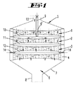
図1と図2に示される装置は、基板上におけるOLED構造の堆積のためにキャリアガスの中で運ばれる蒸気を生成するためのものであり、ハウジング5を有する。ハウジング5は、加熱されるハウジング壁を有する。ハウジング5の注入部には、キャリアガス供給ライン13が配置されている。それを通ってキャリアガス、例えば窒素がハウジングの注入部に導入される。ハウジング5の注入部は、じょうご状に外に広がる。それから、ハウジングは合計4つのオープンセルの発泡体ボディを有する円筒形に続く。それらの発泡体ボディはグラファイトまたは同様の適切な材料からなり、流れ方向に順々に配置されている。発泡体ボディ1,2,3,4の各々はハウジング5の横断面全体を満たす。発泡体ボディは、例えば36cm2の断面積とおよそ1cmの厚さを持つことができる。それらは250μmの細孔幅(インチ当たり100個の細孔)と約97%のオープン断面エリアを持つ。発泡体ボディ1,2,3,4の固体発泡体は導電性があり、発泡体ボディはそれらを流れる電流によって加熱されることができる。図2と図3には、関連のある供給ライン15,16,17,18とコンタクト15’が示される。コンタクト15’、16’、17’、18’で、調節器31によって調節された電圧が印加されるか、または調節された電流が供給されることができる。
The apparatus shown in FIGS. 1 and 2 is for generating vapor carried in a carrier gas for the deposition of an OLED structure on a substrate and has a
エアロゾル供給パイプ9を通って、キャリアガス、例えば窒素と例えばAlQ3から成るエアロゾルが第1の発泡体ボディ1と第2の発泡体ボディ2の間の中間空間10に供給されることができる。流れ方向における第2の発泡体ボディ2と流れ方向における第3の発泡体ボディ3の間に中間空間11が位置している。
Through an aerosol supply pipe 9, a carrier gas, for example an aerosol consisting of nitrogen and AlQ 3 , for example, can be supplied to the
また、流れ方向における第3の発泡体ボディ3と流れ方向における第4の発泡体ボディ4の間に他の中間空間12が位置している。冷却ガス供給パイプ14が中間空間12につながり、それを通って冷却された冷却ガスが供給される。ただし、冷却ガスは必要に応じて室温であることができる。また、冷却ガスは窒素であることができる。
Further, another
ハウジング5の円筒形部分は本実施形態に係る4つの発泡体ボディ1から4を収容するが、それは加熱された円すい状の面7と円筒形部分8を有する排気部分に接続される。キャリアガス・蒸気混合物は、その結果として形成される排気チャンネル6の中を通る。
The cylindrical part of the
本実施形態では、4つの発泡体ボディが前後に示される。本実施形態では示されないが、発泡体ボディの数はこれより多くてもよいし、少なくてもよい。 In this embodiment, four foam bodies are shown front and back. Although not shown in this embodiment, the number of foam bodies may be larger or smaller.
必須の構成要素は、第1の発泡体ボディと、少なくとも第2の発泡体ボディである。第1の発泡体ボディでエアロゾル供給パイプ9を通って供給されるエアロゾルが気化される。第2の発泡体ボディは、第1の発泡体ボディの後ろに配置されており、気化温度よりも低い温度に調節されることができる。それで、蒸気は開孔発泡体のセル壁においてほぼ完全に凝結することができ、キャリアガスのみが排気チャンネル6を通って流れる。 The essential components are a first foam body and at least a second foam body. The aerosol supplied through the aerosol supply pipe 9 in the first foam body is vaporized. The second foam body is disposed behind the first foam body and can be adjusted to a temperature lower than the vaporization temperature. Thus, the vapor can condense almost completely at the cell wall of the open foam and only the carrier gas flows through the exhaust channel 6.
図1と図2に示す本実施形態の場合、エアロゾル供給パイプ9の開口9’が発泡体ボディ1の間で中間空間10の中に突き出す。発泡体ボディ1はキャリアガス供給パイプ13を通って供給されるキャリアガスのための予熱デバイスを形成する。予熱デバイス1は、気化温度に加熱され、また、エアロゾルの気化を引き起こすことができる。けれども、エアロゾルは逆拡散によって予熱ユニット1の中に流れを遡って拡散することができる。エアロゾルの実質的な気化は、流れ方向における第2の発泡体ボディの中で、すなわち気化デバイス2の中で起こる。従って、発泡体ボディ2と発泡体ボディ3の間の中間空間11に入るガスは、純粋なキャリアガス・蒸気混合物である。
In the case of this embodiment shown in FIGS. 1 and 2, the opening 9 ′ of the aerosol supply pipe 9 protrudes into the
発泡体ボディ3と発泡体ボディ4は調節デバイスを形成する。調節デバイス3,4は気化温度に相当する温度まで加熱されることができる。この動作モードでは、そのデバイスは蒸気移動フェーズで動作する。蒸気とキャリアガスは、調節デバイス3,4を通って自由に流れる。
The
キャリアガスは、気化温度に加熱されるが、この動作モードにおいて冷却ガス供給パイプ14を通って入ることができる。けれども、望ましくは蒸気移動フェーズの間に冷却ガス供給パイプ14を通って調節デバイスの2つの発泡体ボディ3,4の間の中間空間12にガスは全く入らない。
The carrier gas is heated to the vaporization temperature, but can enter through the cooling
休止フェーズでは、冷却ガス供給パイプ14を通って冷却ガスが中間空間12に導入される。この動作モードにおいて、調節デバイスの2つの固体発泡体は積極的には加熱されない。これは、中間空間12に隣接する発泡体ボディ3,4の領域がおよそ20℃冷却されるという結果をもたらす。特に、下流に配置された発泡体ボディ4は、気化デバイス2で発生した蒸気が薄い膜である発泡体ボディのセル壁に凝結する凝結温度に冷却される。従って、凝結温度への調節デバイス3,4の冷却に起因して、全圧またはキャリアガスの流れが有意に影響を及ぼされることなく、排気チャンネル6においてキャリアガスの中の蒸気濃度はゼロに削減されることができる。冷却ガスの流れは、冷却ガス供給パイプ14を通ってガス全体の流れに送り込まれるが、キャリアガス供給パイプ13を通って供給されるキャリアガスにおける対応する減少によって埋め合わされることができる。
In the idle phase, the cooling gas is introduced into the
冷却ガスの流れの減少によって、または調節デバイス3,4を通って電流を流すことによる調節デバイス3,4の適切な温度調節によって、調節デバイス3,4の温度は凝結温度より上に上げられることができる。それで、調節デバイスのセル壁上に堆積する薄い膜は制御された方法で気化されることができる。これは、その装置の蒸気移動率を精密に調節することを可能にする。
The temperature of the
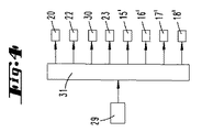
図2は、さらにエアロゾル発生器19とマスフローコントローラ20の概略図を示す。マスフローコントローラ20は、エアロゾル発生器19を通って流れるキャリアガスを調節するために使われる。従って、エアロゾル発生器で生成された粒子は、エアロゾル供給パイプ9を通って中間空間10の中に流れるガスで運ばれる。
FIG. 2 further shows a schematic diagram of the
マスフローコントローラ22によって調節されたキャリアガスの流れは、加熱デバイス21によって加熱されることができる。けれども、もし予熱ユニット1が十分に大きい寸法であるならば、加熱デバイス21は必要ではない。
The carrier gas flow regulated by the
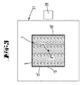
符号23は、冷却ガス14のための温度制御デバイスを示すために使用される。温度制御デバイス23は任意的である。また、冷却ガス14はマスフローコントローラ30によって調節される。ガス移動デバイスのハウジング5は、CVD反応炉の反応炉ハウジング27の中に配置される。反応炉ハウジング27内には、シャワーヘッド状のガス注入ボディ24が配置されている。ガス注入ボディ24はガス移動デバイスのガス排気チャンネル6によって供給される。ガス排気チャンネル6の中には、センサー29が配置されている。センサー29はキャリアガスの流れの中の蒸気濃度を決定することができる。
ガス注入ボディ24は、基板26に面する側に、複数のガス放出開口を有する。ガス放出開口を通ってキャリアガス・蒸気混合物が処理チャンバーに流れることができる。処理チャンバーの底は温度制御されるサセプタ25を形成する。例えば、気化された有機材料の層がサセプタ25の上に置かれている基板26の表面に堆積するように、サセプタ25は温度制御されることができる。
The
真空ポンプ28によって、処理チャンバー内と気化デバイス内の全圧がおよそ1ミリバールに下がるように調節されことができる。
By means of a
予熱デバイス1、気化デバイス2または調節デバイス3,4が加熱される温度は、気化される材料に依存する。それらの温度は通常250℃と350℃の間である。
The temperature at which the
図4は制御ループの概略図を示す。制御ループでは、センサー29と調節器31によって蒸気生成率は一定の指定値に調節されることができる。この目的のために、調節器31は、マスフローコントローラ20を使ってエアロゾルの質量流量を制御し、マスフローコントローラ22を使ってキャリアガスの質量流量を制御し、マスフローコントローラ30を使って冷却ガスの質量流量を制御し、温度制御デバイス23を使って冷却ガスの温度を制御し、コンタクト15’、16’、17’、18’を通って発泡体ボディ1,2,3,4に供給される電流を用いて加熱可能な発泡体ボディ1から4に供給される加熱パワーのレベルを制御する。
FIG. 4 shows a schematic diagram of the control loop. In the control loop, the steam generation rate can be adjusted to a certain specified value by the
上述した記載は、全体として本出願に含まれる複数の発明の説明として与えられる。そしてそれらは各々独立して少なくとも以下の特徴の組み合わせによって先行技術を超える。 The above description is given as an explanation of several inventions included in this application as a whole. And each independently exceeds the prior art by a combination of at least the following features.
流れ方向において気化デバイス1,2の後に配置された調節デバイス3,4を通るキャリアガスによって蒸気が運ばれ、当該調節デバイス3,4が第2の熱移動面を含んでおり、蒸気移動フェーズにおいて当該第2の熱移動面が第1の調節温度に調節され、当該蒸気移動フェーズでは蒸気が当該第2の熱移動面に凝結することなしに前記調節デバイス3,4を通って流れ、休止フェーズにおいて当該第2の熱移動面が第2の調節温度に調節され、当該休止フェーズでは少なくとも蒸気の一部が当該第2の熱移動面に凝結することを特徴とする蒸気発生方法。
Vapor is carried in the flow direction by a carrier gas passing through the
前記調節デバイス3,4が特に冷却ガスを導入することによって前記第2の調節温度に積極的に冷却され、特に冷却ガスが前記気化デバイス1,2または前記調節デバイス3,4の間、または前記調節デバイス3,4の2つの要素の間で中間空間12に持ち込まれることが提供されることを特徴とする蒸気発生方法。
The
前記第2の調節温度で前記調節デバイス3,4の熱移動面に堆積した蒸気の凝縮物が、前記気化温度に対応する調節温度で気化されることを特徴とする蒸気発生方法。
A steam generation method, characterized in that the vapor condensate deposited on the heat transfer surfaces of the
蒸気の質量流量率が、調節器31によって調節される前記調節デバイス3,4の温度によって調節され、特に前記調節デバイス3,4の加熱デバイスの加熱パワーを制御することによって、および/または前記調節デバイス3,4への冷却ガスの質量流量によって調節されることを特徴とする蒸気発生方法。
The mass flow rate of the steam is adjusted by the temperature of the adjusting
流れ方向において気化デバイス1,2の後に配置されており、第2の熱移動面を有する調節デバイス3,4を備え、当該第2の熱移動面が少なくともいくつかの領域において調節温度に調節され、少なくとも蒸気が当該第2の熱移動面に凝結する凝結温度の値と気化温度の値とを当該調節温度が含むことができることを特徴とする蒸気発生装置。
Arranged after the
前記熱移動面が発泡体ボディの開孔セルの壁の表面によって形成されており、特に当該発泡体ボディが導電性材料でできており、当該発泡体ボディを通って電流を流すことによって加熱されることができ、インチ当たり500個から200個、望ましくは100個の細孔の多孔率を有するか、および/または前記発泡体ボディの表面における全てのオープンエリアの割合が90%より大きいことが提供されることを特徴とする蒸気発生装置または蒸気発生方法。 The heat transfer surface is formed by the surface of the open cell wall of the foam body, in particular the foam body is made of a conductive material and is heated by passing an electric current through the foam body. Have a porosity of 500 to 200, preferably 100 pores per inch, and / or the percentage of all open areas on the surface of the foam body is greater than 90% A steam generating apparatus or a steam generating method characterized by being provided.
前記調節温度を低下させるために前記調節デバイス3,4に冷却ガスを供給するための冷却ガス供給パイプ14を備えることを特徴とする蒸気発生装置または蒸気発生方法。
A steam generating apparatus or a steam generating method comprising a cooling
前記気化デバイス1,2および/または前記調節デバイス3,4が各々流れ方向に順々に配置された2つの多孔質の発泡体ボディを含んでおり、前記気化デバイス1において上流の発泡体ボディがキャリアガスに対する予熱デバイスであって中間空間10によって前記気化デバイス2である第2の発泡体ボディから離れて間隔を空けられており、当該中間空間10の中にエアロゾル供給パイプ9が粒子を含むエアロゾルを供給するために送り込まれることが特に提供され、および/または流れ方向に順々に配置された前記調節デバイス3,4の2つ発泡体ボディが中間空間12によってお互いから分離されており、当該中間空間12の中に冷却ガス供給パイプ14が冷却ガスを導入するために送り込まれることが特に提供されることを特徴とする蒸気発生装置または蒸気発生方法。
The
実質的に同じように設計された4つの発泡体ボディ1,2,3,4が蒸発器ハウジングの中で流れ方向に順々に配置されており、前記調節デバイス3,4の下流に配置された前記ハウジング7,8の壁が前記気化温度よりも上である温度に加熱されることを特徴とする蒸気発生装置または蒸気発生方法。
Four
キャリアガスの中の粒子圧力または蒸気の濃度を測定するために前記調節デバイス3,4の下流に配置されたセンサー29を備えることを特徴とする蒸気発生装置または蒸気発生方法。
A steam generating apparatus or a steam generating method comprising a
前記デバイスがガス注入ボディ24とサセプタ25を含むCVDまたはPVD反応炉の一部であり、前記ガス注入ボディ24を通るキャリアガスによって運ばれる蒸気が前記サセプタ25の上に置かれた基板26の方に運ばれ、当該蒸気が化学反応または温度低下に起因して凝結し、特に真空ポンプ28がCVDまたはPVD反応炉の内部を空にするために提供されることを特徴とする蒸気発生装置または蒸気発生方法。
A
開示される全ての特徴は(個々に、しかしまた、お互いとの組み合わせで)本発明に不可欠である。これによってまた、本出願の開示は、関連した/添付する優先権書類(先願のコピー)の特徴を本出願の請求項に含める目的のために、これらの書類全部の開示内容を包含する。それらの特徴を持った従属項は、特にこれらの請求項に基づいて部分的な出願を実行するために、先行技術の独立した発明の改良を特徴づける。 All the disclosed features (individually but also in combination with each other) are essential to the present invention. Again, the disclosure of this application includes the disclosure content of all of these documents for the purpose of including relevant / attached priority documents (copies of prior applications) in the claims of this application. The dependent claims with their characteristics characterize the prior art independent invention improvements, in particular for carrying out a partial application based on these claims.
1…予熱デバイス
2…気化デバイス
3…調節デバイス
4…調節デバイス
5…ハウジング
6…排気チャンネル
7…円すい状の面、ハウジング壁
8…円筒形部分、ハウジング壁
9…エアロゾル供給パイプ
9’…開口
10…中間空間
11…中間空間
12…中間空間
13…キャリアガス供給パイプ
14…冷却ガス供給パイプ
15…電気供給ライン
15’…コンタクト
16…電気供給ライン
16’…コンタクト
17…電気供給ライン
17’…コンタクト
18…電気供給ライン
18’…コンタクト
19…エアロゾル発生器
20…マスフローコントローラ
21…加熱デバイス
22…マスフローコントローラ
23…温度制御デバイス
24…ガス注入ボディ
25…サセプタ
26…基板
27…反応炉ハウジング
28…真空ポンプ
29…センサー
30…マスフローコントローラ
31…調節器
DESCRIPTION OF
当該蒸気発生装置がガス注入ボディ24とサセプタ25を含むCVDまたはPVD反応炉の一部であり、前記ガス注入ボディ24を通るキャリアガスによって運ばれる蒸気が前記サセプタ25の上に置かれた基板26の方に運ばれ、当該蒸気が化学反応または温度低下に起因して凝結し、特に真空ポンプ28がCVDまたはPVD反応炉の内部を空にするために提供されることを特徴とする蒸気発生装置または蒸気発生方法。
The steam generator is part of a CVD or PVD reactor that includes a
Claims (12)
単一または多段の気化デバイス(1,2)において固体または液体の粒子を第1の熱移動面と接触させることによって気化の熱が当該粒子に伝えられ、当該第1の熱移動面が気化温度に達し、
粒子の蒸発によって生成された蒸気がキャリアガスの流れ方向にキャリアガスによって前記気化デバイス(1,2)の外に運ばれ、
流れ方向において前記気化デバイス(1,2)の後に配置された単一または多段の調節デバイス(3,4)を通るキャリアガスによって蒸気が運ばれ、
前記調節デバイス(3,4)が第2の熱移動面を含んでおり、少なくとも蒸気移動フェーズにおいて、当該第2の熱移動面が第1の調節温度に調節され、当該第1の調節温度で蒸気が当該第2の熱移動面に材料の堆積する方法で凝結することなしに前記調節デバイス(3,4)を通って流れ、
少なくとも休止フェーズにおいて、前記第2の熱移動面が第2の調節温度に調節され、当該第2の調節温度で少なくとも蒸気の一部が前記第2の熱移動面に材料の堆積する方法で凝結する、
ことを特徴とする蒸気発生方法。 A method for generating steam in a CVD or PVD apparatus,
By contacting solid or liquid particles with the first heat transfer surface in a single or multistage vaporization device (1, 2), the heat of vaporization is transferred to the particles, and the first heat transfer surface is the vaporization temperature. Reached
Vapor generated by the evaporation of particles is carried out of the vaporization device (1, 2) by the carrier gas in the direction of the carrier gas flow,
Vapor is carried by the carrier gas through a single or multi-stage regulating device (3, 4) arranged after the vaporization device (1, 2) in the flow direction;
The conditioning device (3, 4) includes a second heat transfer surface, and at least in the steam transfer phase, the second heat transfer surface is adjusted to a first adjusted temperature, and at the first adjusted temperature, Steam flows through the conditioning device (3, 4) without condensing in a way that material is deposited on the second heat transfer surface;
At least in the quiescent phase, the second heat transfer surface is adjusted to a second regulated temperature, and at the second regulated temperature, at least a portion of the vapor condenses in a manner that material is deposited on the second heat transfer surface. To
A method for generating steam.
特に冷却ガスが前記気化デバイス(1,2)または前記調節デバイス(3,4)の間、または前記調節デバイス(3,4)の2つの要素の間で中間空間(12)に持ち込まれることが提供される、
ことを特徴とする請求項1に記載の蒸気発生方法。 The regulating device (3, 4) is actively cooled to the second regulating temperature, in particular by introducing a cooling gas,
In particular, a cooling gas may be brought into the intermediate space (12) between the vaporization device (1,2) or the adjustment device (3,4) or between two elements of the adjustment device (3,4). Provided,
The steam generation method according to claim 1.
単一または多段の気化デバイス(1,2)を有し、当該気化デバイス(1,2)に置かれた固体または液体の粒子に気化の熱を伝えるために気化温度に加熱されることができる第1の熱移動面を当該気化デバイス(1,2)が含み、
粒子の気化によって生成された蒸気が、キャリアガスの流れ方向にキャリアガスによって前記気化デバイス(1,2)の外に運ばれ、
流れ方向において前記気化デバイス(1,2)の後に配置されており、第2の熱移動面を有する単一または多段の調節デバイス(3,4)を備え、
前記第2の熱移動面が少なくともいくつかの領域において調節温度に調節され、
少なくとも蓄積質量を形成する前記第2の熱移動面に蒸気が凝結する凝結温度の値と、蓄積質量が前記第2の熱移動面に形成されない気化温度の値とを前記調節温度が含むことができる、
ことを特徴とする蒸気発生装置。 A steam generator for CVD or PVD apparatus, in particular for carrying out the method according to any one of claims 1 to 4,
It has a single or multi-stage vaporization device (1,2) and can be heated to the vaporization temperature to transfer the heat of vaporization to solid or liquid particles placed on the vaporization device (1,2) The vaporization device (1, 2) includes a first heat transfer surface,
The vapor generated by the vaporization of the particles is carried out of the vaporization device (1, 2) by the carrier gas in the flow direction of the carrier gas,
Arranged after the vaporization device (1, 2) in the flow direction, comprising a single or multi-stage adjustment device (3,4) having a second heat transfer surface;
The second heat transfer surface is adjusted to a controlled temperature in at least some regions;
The controlled temperature includes at least a condensation temperature value at which steam condenses on the second heat transfer surface forming the accumulated mass and a vaporization temperature value at which accumulated mass is not formed on the second heat transfer surface. it can,
A steam generator characterized by that.
前記発泡体ボディが導電性材料でできており、前記発泡体ボディを通って電流を流すことによって加熱されることができ、インチ当たり500個から200個、望ましくは100個の細孔の多孔率を有するか、および/または前記発泡体ボディの表面における全てのオープンエリアの割合が90%より大きいことが特に提供される、
ことを特徴とする請求項5に記載の蒸気発生装置または請求項1ないし4のいずれか1項に記載の蒸気発生方法。 The heat transfer surface is formed by the surface of the porous cell wall of the foam body;
The foam body is made of a conductive material and can be heated by passing an electric current through the foam body and has a porosity of 500 to 200, preferably 100 pores per inch And / or is provided in particular that the proportion of all open areas on the surface of the foam body is greater than 90%,
The steam generation apparatus according to claim 5 or the steam generation method according to any one of claims 1 to 4.
前記気化デバイス(1)において、上流の発泡体ボディがキャリアガスに対する予熱デバイスであって中間空間(10)によって前記気化デバイス(2)である第2の発泡体ボディから離れて間隔を空けられており、当該中間空間(10)の中にエアロゾル供給パイプ(9)が粒子を含むエアロゾルを供給するために送り込まれることが特に提供され、
および/または流れ方向に順々に配置された前記調節デバイス(3,4)の2つの発泡体ボディが中間空間(12)によってお互いから分離されており、当該中間空間(12)の中に冷却ガス供給パイプ(14)が冷却ガスを導入するために送り込まれることが特に提供される、
ことを特徴とする請求項5ないし7のいずれか1項に記載の蒸気発生装置もしくは請求項1ないし4のいずれか1項または請求項6または請求項7に記載の蒸気発生方法。 The vaporization device (1,2) and / or the adjustment device (3,4) each comprise two open foam bodies arranged one after the other in the flow direction;
In said vaporization device (1), the upstream foam body is a preheating device for carrier gas and is spaced apart from the second foam body which is said vaporization device (2) by an intermediate space (10) In particular, it is provided that an aerosol supply pipe (9) is fed into the intermediate space (10) to supply aerosol containing particles;
And / or two foam bodies of the adjusting device (3, 4) arranged one after the other in the flow direction are separated from each other by an intermediate space (12) and cooled in the intermediate space (12) It is specifically provided that the gas supply pipe (14) is fed to introduce cooling gas,
The steam generation apparatus according to any one of claims 5 to 7, or the steam generation method according to any one of claims 1 to 4, or 6 or 7.
前記調節デバイス(3,4)の下流に配置されたハウジング(7,8)の壁が前記気化温度よりも上である温度に加熱される、
ことを特徴とする請求項5ないし8のいずれか1項に記載の蒸気発生装置もしくは請求項1ないし4のいずれか1項または請求項6ないし8のいずれか1項に記載の蒸気発生方法。 Four foam bodies (1, 2, 3, 4), designed in substantially the same way, are arranged one after the other in the flow direction in the evaporator housing,
The walls of the housing (7, 8) arranged downstream of the regulating device (3, 4) are heated to a temperature above the vaporization temperature,
The steam generation apparatus according to any one of claims 5 to 8, or the steam generation method according to any one of claims 1 to 4, or the steam generation method according to any one of claims 6 to 8.
前記ガス注入ボディ(24)を通るキャリアガスによって運ばれる蒸気が前記サセプタ(25)の上に置かれた基板(26)の方に運ばれ、当該蒸気が化学反応または温度低下に起因して凝結し、
特に真空ポンプ(28)がCVDまたはPVD反応炉の内部を空にするために提供される、
ことを特徴とする請求項5ないし10のいずれか1項に記載の蒸気発生装置もしくは請求項1ないし4のいずれか1項または請求項6ないし10のいずれか1項に記載の蒸気発生方法。 The apparatus is part of a CVD or PVD reactor comprising a gas injection body (24) and a susceptor (25);
Vapor carried by the carrier gas through the gas injection body (24) is carried towards the substrate (26) placed on the susceptor (25), and the vapor condenses due to a chemical reaction or a temperature drop. And
In particular, a vacuum pump (28) is provided to empty the interior of the CVD or PVD reactor,
The steam generation device according to any one of claims 5 to 10, or the steam generation method according to any one of claims 1 to 4, or the steam generation method according to any one of claims 6 to 10.
Applications Claiming Priority (3)
| Application Number | Priority Date | Filing Date | Title |
|---|---|---|---|
| DE102014109194.9A DE102014109194A1 (en) | 2014-07-01 | 2014-07-01 | Apparatus and method for generating a vapor for a CVD or PVD device |
| DE102014109194.9 | 2014-07-01 | ||
| PCT/EP2015/063530 WO2016000958A1 (en) | 2014-07-01 | 2015-06-17 | Device and method for generating vapor for a cvd- or pvd device |
Publications (2)
| Publication Number | Publication Date |
|---|---|
| JP2017519908A true JP2017519908A (en) | 2017-07-20 |
| JP6752199B2 JP6752199B2 (en) | 2020-09-09 |
Family
ID=53488303
Family Applications (1)
| Application Number | Title | Priority Date | Filing Date |
|---|---|---|---|
| JP2017519800A Active JP6752199B2 (en) | 2014-07-01 | 2015-06-17 | Steam generators and steam generator methods for CVD or PVD equipment |
Country Status (7)
| Country | Link |
|---|---|
| US (1) | US10501847B2 (en) |
| JP (1) | JP6752199B2 (en) |
| KR (1) | KR20170026532A (en) |
| CN (1) | CN106661719B (en) |
| DE (1) | DE102014109194A1 (en) |
| TW (1) | TWI698538B (en) |
| WO (1) | WO2016000958A1 (en) |
Cited By (3)
| Publication number | Priority date | Publication date | Assignee | Title |
|---|---|---|---|---|
| CN111560606A (en) * | 2020-05-21 | 2020-08-21 | 北京北方华创微电子装备有限公司 | Heating furnace body control method in semiconductor heat treatment equipment, heating furnace body and equipment |
| JP2020143315A (en) * | 2019-03-05 | 2020-09-10 | 日本エア・リキード合同会社 | Solid material container |
| JP2021505758A (en) * | 2017-12-07 | 2021-02-18 | インテグリス・インコーポレーテッド | How to operate the chemical delivery system and the chemical delivery system |
Families Citing this family (8)
| Publication number | Priority date | Publication date | Assignee | Title |
|---|---|---|---|---|
| DE102017103047A1 (en) * | 2016-11-29 | 2018-05-30 | Aixtron Se | aerosol evaporator |
| CN106978590B (en) * | 2017-04-26 | 2019-06-25 | 武汉华星光电技术有限公司 | Evaporation coating device |
| DE102017126126A1 (en) * | 2017-11-08 | 2019-05-09 | Aixtron Se | Method and device for generating a vapor by the use of control data obtained in a control mode |
| DE102018004987B4 (en) | 2018-06-20 | 2022-08-25 | Singulus Technologies Ag | Method and device for providing steam |
| US11274367B2 (en) * | 2018-07-24 | 2022-03-15 | Lintec Co., Ltd. | Vaporizer |
| DE102019129176A1 (en) * | 2019-10-29 | 2021-04-29 | Apeva Se | Method and device for depositing organic layers |
| DE102020122800A1 (en) * | 2020-09-01 | 2022-03-03 | Apeva Se | Device for depositing OLED layers with a run/vent line |
| US11459654B2 (en) * | 2020-11-19 | 2022-10-04 | Eugenus, Inc. | Liquid precursor injection for thin film deposition |
Citations (5)
| Publication number | Priority date | Publication date | Assignee | Title |
|---|---|---|---|---|
| JP2006525422A (en) * | 2003-04-30 | 2006-11-09 | ビーエーエスエフ アクチェンゲゼルシャフト | Finely divided organic semiconductor compound and vapor deposition method on support |
| JP2010242132A (en) * | 2009-04-02 | 2010-10-28 | Mitsubishi Heavy Ind Ltd | Film-forming method and film-forming apparatus |
| WO2012175307A1 (en) * | 2011-06-22 | 2012-12-27 | Aixtron Se | Method and device for depositing oleds |
| WO2012175334A2 (en) * | 2011-06-22 | 2012-12-27 | Aixtron Se | Method and device for depositing oleds, in particular evaporation device therefor |
| WO2012175124A1 (en) * | 2011-06-22 | 2012-12-27 | Aixtron Se | Vapor deposition material source and method for making same |
Family Cites Families (14)
| Publication number | Priority date | Publication date | Assignee | Title |
|---|---|---|---|---|
| US2447789A (en) * | 1945-03-23 | 1948-08-24 | Polaroid Corp | Evaporating crucible for coating apparatus |
| USRE34806E (en) * | 1980-11-25 | 1994-12-13 | Celestech, Inc. | Magnetoplasmadynamic processor, applications thereof and methods |
| US4981102A (en) * | 1984-04-12 | 1991-01-01 | Ethyl Corporation | Chemical vapor deposition reactor and process |
| US4885211A (en) * | 1987-02-11 | 1989-12-05 | Eastman Kodak Company | Electroluminescent device with improved cathode |
| US4769292A (en) * | 1987-03-02 | 1988-09-06 | Eastman Kodak Company | Electroluminescent device with modified thin film luminescent zone |
| US20030026601A1 (en) | 2001-07-31 | 2003-02-06 | The Arizona Board Of Regents On Behalf Of The University Of Arizona | Vapor deposition and in-situ purification of organic molecules |
| US8128753B2 (en) * | 2004-11-19 | 2012-03-06 | Massachusetts Institute Of Technology | Method and apparatus for depositing LED organic film |
| CA2588793C (en) * | 2004-11-30 | 2015-01-13 | Agrium Inc. | Process and apparatus for coating a controlled release product in a rotating drum |
| US7368541B2 (en) * | 2004-12-01 | 2008-05-06 | Merck & Co., Inc. | Trace amine receptor 1 of the African green monkey |
| JP4911555B2 (en) * | 2005-04-07 | 2012-04-04 | 国立大学法人東北大学 | Film forming apparatus and film forming method |
| JP5474089B2 (en) * | 2009-12-09 | 2014-04-16 | 株式会社アルバック | Organic thin film forming apparatus and organic material film forming method |
| JP5877245B2 (en) * | 2011-06-22 | 2016-03-02 | アイクストロン、エスイー | Vapor deposition method and vapor deposition apparatus |
| WO2012175128A1 (en) * | 2011-06-22 | 2012-12-27 | Aixtron Se | Vapor deposition system and supply head |
| JP6038043B2 (en) * | 2011-11-21 | 2016-12-07 | 株式会社日立国際電気 | Substrate processing apparatus, semiconductor device manufacturing method, and program |
-
2014
- 2014-07-01 DE DE102014109194.9A patent/DE102014109194A1/en not_active Withdrawn
-
2015
- 2015-06-17 JP JP2017519800A patent/JP6752199B2/en active Active
- 2015-06-17 KR KR1020177002461A patent/KR20170026532A/en not_active Application Discontinuation
- 2015-06-17 WO PCT/EP2015/063530 patent/WO2016000958A1/en active Application Filing
- 2015-06-17 CN CN201580035081.1A patent/CN106661719B/en not_active Expired - Fee Related
- 2015-06-17 US US15/316,646 patent/US10501847B2/en not_active Expired - Fee Related
- 2015-06-30 TW TW104121097A patent/TWI698538B/en not_active IP Right Cessation
Patent Citations (5)
| Publication number | Priority date | Publication date | Assignee | Title |
|---|---|---|---|---|
| JP2006525422A (en) * | 2003-04-30 | 2006-11-09 | ビーエーエスエフ アクチェンゲゼルシャフト | Finely divided organic semiconductor compound and vapor deposition method on support |
| JP2010242132A (en) * | 2009-04-02 | 2010-10-28 | Mitsubishi Heavy Ind Ltd | Film-forming method and film-forming apparatus |
| WO2012175307A1 (en) * | 2011-06-22 | 2012-12-27 | Aixtron Se | Method and device for depositing oleds |
| WO2012175334A2 (en) * | 2011-06-22 | 2012-12-27 | Aixtron Se | Method and device for depositing oleds, in particular evaporation device therefor |
| WO2012175124A1 (en) * | 2011-06-22 | 2012-12-27 | Aixtron Se | Vapor deposition material source and method for making same |
Cited By (6)
| Publication number | Priority date | Publication date | Assignee | Title |
|---|---|---|---|---|
| JP2021505758A (en) * | 2017-12-07 | 2021-02-18 | インテグリス・インコーポレーテッド | How to operate the chemical delivery system and the chemical delivery system |
| KR20220146684A (en) * | 2017-12-07 | 2022-11-01 | 엔테그리스, 아이엔씨. | Chemical delivery system and method of operating the chemical delivery system |
| KR102611640B1 (en) | 2017-12-07 | 2023-12-11 | 엔테그리스, 아이엔씨. | Chemical delivery system and method of operating the chemical delivery system |
| JP7401433B2 (en) | 2017-12-07 | 2023-12-19 | インテグリス・インコーポレーテッド | Chemical delivery systems and how to operate them |
| JP2020143315A (en) * | 2019-03-05 | 2020-09-10 | 日本エア・リキード合同会社 | Solid material container |
| CN111560606A (en) * | 2020-05-21 | 2020-08-21 | 北京北方华创微电子装备有限公司 | Heating furnace body control method in semiconductor heat treatment equipment, heating furnace body and equipment |
Also Published As
| Publication number | Publication date |
|---|---|
| DE102014109194A1 (en) | 2016-01-07 |
| CN106661719B (en) | 2019-09-03 |
| TWI698538B (en) | 2020-07-11 |
| CN106661719A (en) | 2017-05-10 |
| WO2016000958A1 (en) | 2016-01-07 |
| KR20170026532A (en) | 2017-03-08 |
| US10501847B2 (en) | 2019-12-10 |
| TW201612337A (en) | 2016-04-01 |
| JP6752199B2 (en) | 2020-09-09 |
| US20180148836A1 (en) | 2018-05-31 |
Similar Documents
| Publication | Publication Date | Title |
|---|---|---|
| JP6752199B2 (en) | Steam generators and steam generator methods for CVD or PVD equipment | |
| TW202113141A (en) | Film-forming material mixed-gas forming device and film forming device | |
| US20100236480A1 (en) | Raw material gas supply system and film forming apparatus | |
| KR102003527B1 (en) | Method and device for depositing oleds | |
| JP6606547B2 (en) | Steam generating apparatus and steam generating method for generating steam for a CVD or PVD apparatus from a plurality of liquid or solid raw materials | |
| JP5989107B2 (en) | Organic starting material deposition method, evaporation apparatus and deposition apparatus | |
| WO2001036707A1 (en) | Apparatus and method for delivery of precursor vapor from low vapor pressure liquid sources to a cvd chamber | |
| US6424800B1 (en) | Bubbler | |
| JP2004140328A (en) | Gas supply system and treatment system | |
| JP2004115916A (en) | Organic vapor deposition system, and organic vapor deposition method | |
| WO2007037268A1 (en) | Raw material feeder and vapor deposition apparatus | |
| TW200304959A (en) | Method for coating a substrate and device for carrying out the method | |
| KR101149450B1 (en) | Deposition source, film forming apparatus and film forming method | |
| KR20170072906A (en) | Temperature-controlled gas supply line with dilution gas flows supplied at multiple locations | |
| US20170067155A1 (en) | Vapor deposition device and method employing plasma as an indirect heating medium | |
| KR101773038B1 (en) | Depositing apparatus having vaporizer and depositing method | |
| JP5265460B2 (en) | Film forming method and film forming apparatus | |
| KR20010077002A (en) | Apparatus for vaporizing a liquid source | |
| WO2022018965A1 (en) | Vaporizer | |
| KR20070006460A (en) | Gas feeding line | |
| JP2011021264A (en) | Film deposition system | |
| TW201631184A (en) | Device for depositing a layer on a substrate |
Legal Events
| Date | Code | Title | Description |
|---|---|---|---|
| A521 | Request for written amendment filed |
Free format text: JAPANESE INTERMEDIATE CODE: A523 Effective date: 20170228 |
|
| A621 | Written request for application examination |
Free format text: JAPANESE INTERMEDIATE CODE: A621 Effective date: 20180613 |
|
| A977 | Report on retrieval |
Free format text: JAPANESE INTERMEDIATE CODE: A971007 Effective date: 20190315 |
|
| A131 | Notification of reasons for refusal |
Free format text: JAPANESE INTERMEDIATE CODE: A131 Effective date: 20190402 |
|
| A131 | Notification of reasons for refusal |
Free format text: JAPANESE INTERMEDIATE CODE: A131 Effective date: 20191023 |
|
| A521 | Request for written amendment filed |
Free format text: JAPANESE INTERMEDIATE CODE: A523 Effective date: 20191226 |
|
| A131 | Notification of reasons for refusal |
Free format text: JAPANESE INTERMEDIATE CODE: A131 Effective date: 20200421 |
|
| A521 | Request for written amendment filed |
Free format text: JAPANESE INTERMEDIATE CODE: A523 Effective date: 20200625 |
|
| TRDD | Decision of grant or rejection written | ||
| A01 | Written decision to grant a patent or to grant a registration (utility model) |
Free format text: JAPANESE INTERMEDIATE CODE: A01 Effective date: 20200729 |
|
| A61 | First payment of annual fees (during grant procedure) |
Free format text: JAPANESE INTERMEDIATE CODE: A61 Effective date: 20200818 |
|
| R150 | Certificate of patent or registration of utility model |
Ref document number: 6752199 Country of ref document: JP Free format text: JAPANESE INTERMEDIATE CODE: R150 |
|
| R250 | Receipt of annual fees |
Free format text: JAPANESE INTERMEDIATE CODE: R250 |