JP2017519552A - Cantilever electrodes for transcutaneous and transcranial stimulation - Google Patents
Cantilever electrodes for transcutaneous and transcranial stimulation Download PDFInfo
- Publication number
- JP2017519552A JP2017519552A JP2016569390A JP2016569390A JP2017519552A JP 2017519552 A JP2017519552 A JP 2017519552A JP 2016569390 A JP2016569390 A JP 2016569390A JP 2016569390 A JP2016569390 A JP 2016569390A JP 2017519552 A JP2017519552 A JP 2017519552A
- Authority
- JP
- Japan
- Prior art keywords
- electrode
- electrode portion
- connector
- active region
- user
- Prior art date
- Legal status (The legal status is an assumption and is not a legal conclusion. Google has not performed a legal analysis and makes no representation as to the accuracy of the status listed.)
- Pending
Links
Images


Classifications
-
- A—HUMAN NECESSITIES
- A61—MEDICAL OR VETERINARY SCIENCE; HYGIENE
- A61N—ELECTROTHERAPY; MAGNETOTHERAPY; RADIATION THERAPY; ULTRASOUND THERAPY
- A61N1/00—Electrotherapy; Circuits therefor
- A61N1/02—Details
- A61N1/04—Electrodes
- A61N1/0404—Electrodes for external use
- A61N1/0472—Structure-related aspects
- A61N1/0492—Patch electrodes
-
- A—HUMAN NECESSITIES
- A61—MEDICAL OR VETERINARY SCIENCE; HYGIENE
- A61N—ELECTROTHERAPY; MAGNETOTHERAPY; RADIATION THERAPY; ULTRASOUND THERAPY
- A61N1/00—Electrotherapy; Circuits therefor
- A61N1/02—Details
- A61N1/04—Electrodes
- A61N1/0404—Electrodes for external use
-
- A—HUMAN NECESSITIES
- A61—MEDICAL OR VETERINARY SCIENCE; HYGIENE
- A61N—ELECTROTHERAPY; MAGNETOTHERAPY; RADIATION THERAPY; ULTRASOUND THERAPY
- A61N1/00—Electrotherapy; Circuits therefor
- A61N1/02—Details
- A61N1/04—Electrodes
- A61N1/0404—Electrodes for external use
- A61N1/0408—Use-related aspects
- A61N1/0456—Specially adapted for transcutaneous electrical nerve stimulation [TENS]
-
- A—HUMAN NECESSITIES
- A61—MEDICAL OR VETERINARY SCIENCE; HYGIENE
- A61N—ELECTROTHERAPY; MAGNETOTHERAPY; RADIATION THERAPY; ULTRASOUND THERAPY
- A61N1/00—Electrotherapy; Circuits therefor
- A61N1/02—Details
- A61N1/04—Electrodes
- A61N1/0404—Electrodes for external use
- A61N1/0472—Structure-related aspects
- A61N1/0476—Array electrodes (including any electrode arrangement with more than one electrode for at least one of the polarities)
-
- A—HUMAN NECESSITIES
- A61—MEDICAL OR VETERINARY SCIENCE; HYGIENE
- A61N—ELECTROTHERAPY; MAGNETOTHERAPY; RADIATION THERAPY; ULTRASOUND THERAPY
- A61N1/00—Electrotherapy; Circuits therefor
- A61N1/02—Details
- A61N1/04—Electrodes
- A61N1/0404—Electrodes for external use
- A61N1/0472—Structure-related aspects
- A61N1/0484—Garment electrodes worn by the patient
-
- A—HUMAN NECESSITIES
- A61—MEDICAL OR VETERINARY SCIENCE; HYGIENE
- A61N—ELECTROTHERAPY; MAGNETOTHERAPY; RADIATION THERAPY; ULTRASOUND THERAPY
- A61N1/00—Electrotherapy; Circuits therefor
- A61N1/18—Applying electric currents by contact electrodes
- A61N1/32—Applying electric currents by contact electrodes alternating or intermittent currents
- A61N1/36—Applying electric currents by contact electrodes alternating or intermittent currents for stimulation
- A61N1/36014—External stimulators, e.g. with patch electrodes
- A61N1/36025—External stimulators, e.g. with patch electrodes for treating a mental or cerebral condition
Abstract
本明細書に記載されるものは、対象(ユーザ)の頭部上または対象の頭頸部上に装着されるように構成されたウェアラブル神経調節機器のためのカンチレバー電極装置である。これらのカンチレバー電極は、ウェアラブル神経調節機器と嵌合して神経調節システムを形成するように構成され得る。また、神経調節のためのカンチレバー電極装置を使用してウェアラブル電気刺激器をユーザの頭部(または頭頸部)に取り付ける方法も記載される。電極アセンブリがウェアラブル神経調節機器と嵌合し、機器が電極アセンブリの一つの部分に装着され、一方で、電極アセンブリの残り部分が体の別の部分に付着し得る。神経調節器は、電極アセンブリの一部分にカンチレバー式に装着され得(たとえば、一端が保持され、一方で、反対側端は浮動状態である)、それが、硬い神経調節機器が多様なユーザの頭のサイズおよび形に適合することを可能にする。Described herein is a cantilever electrode device for a wearable neuromodulation device configured to be worn on a subject's (user's) head or on a subject's head and neck. These cantilever electrodes can be configured to mate with a wearable neuromodulation device to form a neuromodulation system. Also described is a method of attaching a wearable electrical stimulator to a user's head (or head and neck) using a cantilever electrode device for neural modulation. The electrode assembly can mate with a wearable neuromodulation device, and the device can be attached to one part of the electrode assembly while the rest of the electrode assembly can be attached to another part of the body. The neuromodulator can be cantileveredly attached to a portion of the electrode assembly (eg, one end is held while the other end is floating), which is the head of a user with a variety of rigid neuromodulators. Allows to fit the size and shape of the.
Description
関連出願の相互参照
本出願は、以下それぞれの優先権を主張する:「TRANSDERMAL ELECTRICAL STIMULATION ELECTRODE DEGRADATION DETECTION SYSTEMS AND METHODS OF USING THEM」と題する、2014年5月25日に出願された米国特許仮出願第62/002,910号;「FLEXIBLE ELECTRODE DEVICES FOR TRANSDERMAL AND TRANSCRANIAL ELECTRICAL STIMULATION」と題する、2014年10月17日に出願された米国特許仮出願第62/065,577号;「CANTILEVER ELECTRODES FOR TRANSDERMAL AND TRANSCRANIAL STIMULATION」と題する、2014年11月6日に出願された米国特許仮出願第62/076,459号;「SYSTEMS AND METHODS FOR NEUROMODULATION」と題する、2014年11月6日に出願された米国特許仮出願第62/075,896号;「CANTILEVER ELECTRODES FOR TRANSDERMAL AND TRANSCRANIAL STIMULATION」と題する、2015年1月5日に出願された米国特許仮出願第62/099,950号;および「FLEXIBLE ELECTRODE DEVICES FOR TRANSDERMAL AND TRANSCRANIAL ELECTRICAL STIMULATION」と題する、2015年1月5日に出願された米国特許仮出願第62/099,977号。これらの出願それぞれが参照により全体として本明細書に組み入れられる。本出願はまた、以下の意匠特許出願の優先権の恩典を主張する:「ELECTRODE ASSEMBLY FOR TRANSDERMAL AND TRANSCRANIAL STIMULATION」と題する、2014年11月6日に出願された米国意匠特許出願第29/508,490号;「ELECTRODE ASSEMBLY FOR TRANSDERMAL AND TRANSCRANIAL STIMULATION」と題する、2015年1月5日に出願された米国意匠特許出願第29/513,764号;および「ELECTRODE ASSEMBLY FOR TRANSDERMAL AND TRANSCRANIAL STIMULATION」と題する、2015年2月13日に出願された米国意匠特許出願第29/517,629号。これらの出願すべてが参照により全体として本明細書に組み入れられる。
Cross-reference to related applications This application claims the following respective priority: US Provisional Patent Application No. 05/2014, entitled “TRANSDERMAL ELECTRICAL STIMULATION ELECTRODE DEGRADATION DETECTION SYSTEMS AND METHODS OF USING THEM” No. 62 / 002,910; entitled “FLEXIBLE ELECTRODE DEVICES FOR TRANSDERMAL AND TRANSCRANIAL ELECTRICAL STIMULATION”, US Provisional Patent Application No. 62 / 065,577 filed on October 17, 2014; entitled “CANTILEVER ELECTRODES FOR TRANSDERMAL AND TRANSCRANIAL STIMULATION” US Provisional Patent Application No. 62 / 076,459 filed on November 6, 2014; US Provisional Patent Application No. 62 / 075,896 filed on November 6, 2014 entitled “SYSTEMS AND METHODS FOR NEUROMODULATION” US Provisional Patent Application No. 62 / 099,950, filed January 5, 2015, entitled “CANTILEVER ELECTRODES FOR TRANSDERMAL AND TRANSCRANIAL STIMULATION”; and “FLEXIBLE ELECTRODE DEVICES FOR TRANSDERMAL AND TRANSCRANIAL ELECTRICA US Provisional Application No. 62 / 099,977, filed January 5, 2015, entitled “L STIMULATION”. Each of these applications is hereby incorporated by reference in its entirety. This application also claims the benefit of the priority of the following design patent application: U.S. Design Patent Application No. 29 / 508,490, filed November 6, 2014, entitled `` ELECTRODE ASSEMBLY FOR TRANSDERMAL AND TRANSCRANIAL STIMULATION ''. ; US Design Patent Application No. 29 / 513,764, filed January 5, 2015, entitled “ELECTRODE ASSEMBLY FOR TRANSDERMAL AND TRANSCRANIAL STIMULATION”; and “ELECTRODE ASSEMBLY FOR TRANSDERMAL AND TRANSCRANIAL STIMULATION”, February 2015 US design patent application No. 29 / 517,629 filed on 13th. All of these applications are hereby incorporated by reference in their entirety.
本出願は、「WEARABLE TRANSDERMAL ELECTRICAL STIMULATION DEVICES AND METHODS OF USING THEM」と題する、2013年11月26日に出願された米国特許出願第14/091,121号(今や米国特許第8,903,494号);「TRANSDERMAL ELECTRICAL STIMULATION METHODS FOR MODIFYING OR INDUCING COGNITIVE STATE」と題する、2014年6月30日に出願された米国特許出願第14/320,443号(公開番号US-2015-0005840-A1);および「TRANSDERMAL ELECTRICAL STIMULATION DEVICES FOR MODIFYING OR INDUCING COGNITIVE STATE」と題する、2014年6月30日に出願された米国特許出願第14/320,461号(公開番号US-2015-0005841-A1)の一つまたは複数に関連し得る。これらの参考文献それぞれが参照により全体として本明細書に組み入れられる。 This application is a US patent application No. 14 / 091,121 (now US Pat. No. 8,903,494) filed Nov. 26, 2013 entitled “WEARABLE TRANSDERMAL ELECTRICAL STIMULATION DEVICES AND METHODS OF USING THEM”; “TRANSDERMAL ELECTRICAL STIMULATION US Patent Application No. 14 / 320,443 (Publication Number US-2015-0005840-A1), filed June 30, 2014, entitled "Methods For Modulating OR Inducing Cognitive State"; and "TRANSDERMAL ELECTRICAL STIMULATION DEVICES FOR MODIFYING OR" It may relate to one or more of US patent application No. 14 / 320,461 (publication number US-2015-0005841-A1) filed June 30, 2014, entitled "INDUCING COGNITIVE STATE". Each of these references is hereby incorporated by reference in its entirety.
参照による組み入れ
本明細書中で挙げられるすべての刊行物および特許出願は、各個の刊行物または特許出願が参照により本明細書に組み入れられることが明確かつ個別に示される場合と同じ程度に、参照により全体として本明細書に組み入れられる。
INCORPORATION BY REFERENCE All publications and patent applications cited in this specification are referenced to the same extent as if each individual publication or patent application was clearly and individually indicated to be incorporated herein by reference. Is incorporated herein in its entirety.
分野
本明細書に記載されるものは、機器およびシステムを含む非侵襲的神経調節器ならびにそれらの使用方法である。特に、本明細書に記載されるものは、ウェアラブル神経刺激器(神経調節器)に取り付けられ、ユーザの頭および/または首に装着され、ユーザの認知状態を調節するための電気刺激のために使用され得る電極装置(カンチレバー電極および装置を含む)である。
FIELD Described herein are non-invasive neuromodulators, including devices and systems, and methods for their use. In particular, what is described herein is attached to a wearable neurostimulator (neuroregulator) and worn on the user's head and / or neck for electrical stimulation to regulate the user's cognitive status Electrode devices that can be used, including cantilever electrodes and devices.
背景
ニューロン活動に影響する非侵襲的神経調節技術は、侵襲的処置を要することなく、行動、認知状態、知覚および運動出力を調節し、潜在的に変化させることができる。今日まで、経皮非侵襲的神経調節機器の大部分は、一般にコードまたはケーブルを介して神経刺激器に付く一つまたは複数の電極を使用して対象の皮膚に電気エネルギーを印加するが、そのようなコードまたはケーブルは、特に非臨床または非研究環境で装着するには長く、不格好である可能性がある。
Background Non-invasive neuromodulation techniques that affect neuronal activity can modulate and potentially change behavior, cognitive status, sensory and motor output without requiring invasive procedures. To date, the majority of transcutaneous non-invasive neuromodulation devices typically apply electrical energy to a subject's skin using one or more electrodes attached to a neurostimulator via a cord or cable, Such cords or cables can be long and clunky, especially for wearing in non-clinical or non-research environments.
たとえば、ヒトの脳機能に影響を加えるために、経頭蓋交流刺激(以下「tACS」)、経頭蓋直流刺激(以下「tDCS」)、頭蓋電気治療刺激(以下「CES」)および経頭蓋ランダムノイズ刺激(以下「tRNS」)の形態の、頭皮電極を使用する経頭蓋および/または経皮電気刺激(以下「TES」)が使用されてきた。TESのためのシステムおよび方法が開示されている(たとえば、Capelの米国特許第4,646,744号(特許文献1);Haimovichらの米国特許第5,540,736号(特許文献2);Besioらの米国特許第8,190,248号(特許文献3);HagedornおよびThompsonの米国特許第8,239,030号(特許文献4);Biksonらの米国特許出願公開公報第2011/0144716号(特許文献5);およびLebedevらの米国特許出願公開公報第2009/0177243(特許文献6)を参照すること)。多数の電極および高レベルのコンフィギュアビリティを有するtDCSシステムが開示されている(たとえば、Biksonらの米国特許出願公開公報第2012/0209346号(特許文献7)、米国特許出願公開公報第2012/0265261号(特許文献8)および米国特許出願公開公報第2012/0245653号(特許文献9)を参照すること)。 For example, to influence human brain function, transcranial AC stimulation (hereinafter “tACS”), transcranial direct current stimulation (hereinafter “tDCS”), cranial electrotherapy stimulation (hereinafter “CES”) and transcranial random noise. Transcranial and / or transcutaneous electrical stimulation (hereinafter “TES”) using scalp electrodes in the form of stimulation (hereinafter “tRNS”) has been used. Systems and methods for TES are disclosed (eg, Capel US Pat. No. 4,646,744; Haimovich et al. US Pat. No. 5,540,736; Besio et al. US Pat. No. 8,190,248). Hagedorn and Thompson, US Pat. No. 8,239,030 (Patent Document 4); Bikson et al., US Patent Application Publication No. 2011/0144716 (Patent Document 5); and Lebedev et al., US Patent Application Publication No. 2009/0177243 (Patent Document 6)). A tDCS system with multiple electrodes and a high level of configurability has been disclosed (eg, US Patent Application Publication No. 2012/0209346 to Bikson et al., US Patent Application Publication No. 2012/0265261). No. (Patent Document 8) and US Patent Application Publication No. 2012/0245653 (Patent Document 9)).
TESは、痛み、うつ、てんかんおよび耳鳴の治療を含む様々な臨床用途において治療的に使用されてきた。TES神経調節に関する今日までの研究にもかかわらず、TESを送達するための既存のシステムおよび方法は欠如している。特に、効果的かつ快適であり、使いやすい、たとえば非臨床(たとえば家庭)環境において着脱しやすい電極を有するシステムが欠如している。 TES has been used therapeutically in a variety of clinical applications including the treatment of pain, depression, epilepsy and tinnitus. Despite to date research on TES neuromodulation, existing systems and methods for delivering TES are lacking. In particular, there is a lack of systems with electrodes that are effective, comfortable and easy to use, such as easy to attach and detach in non-clinical (eg home) environments.
神経系を標的化する大部分の電気刺激システムは、ユーザインタフェース、電気制御回路、電源(たとえばバッテリ)、ユーザに貼り付けられる電極に通じるワイヤおよび事前に決定および/または構成された電気刺激プロトコルを含むテーブルトップまたはハンドヘルド型のハードウェアを組み込んでいる。従来のシステムは、TES波形を送達するための電極の快適さ、デザインおよび使用に関して制限されている。たとえば、ユーザの体に適合しないような不快で撓みにくい電極を使用し、その結果、不均等なインピーダンス、刺激中の刺激の増大および認知効果の低下を生じさせることがある。さらに、大部分の従来技術電極は、電極によって体に対して保持されるようなウェアラブル神経刺激器への取り付けにはあまり適さない。 Most electrical stimulation systems that target the nervous system include a user interface, electrical control circuitry, a power source (eg, a battery), wires leading to electrodes that are affixed to the user, and pre-determined and / or configured electrical stimulation protocols. Including built-in tabletop or handheld hardware. Conventional systems are limited in terms of electrode comfort, design and use for delivering TES waveforms. For example, uncomfortable and less flexible electrodes that do not fit the user's body may be used, resulting in uneven impedance, increased stimulation during stimulation, and reduced cognitive effects. Furthermore, most prior art electrodes are not well suited for attachment to wearable neurostimulators that are held against the body by the electrodes.
数少ない小型軽量かつおそらくはウェアラブルな神経調節機器が記載されているが、それらのシステムのいずれも、小型軽量のウェアラブル神経刺激器に確実に付くカンチレバー式ボディを有する、患者の頭または頭にエネルギーを印加するための電極(たとえば使い捨て電極)を含まない。したがって、軽量のウェアラブル神経刺激システム、特に、そのような神経調節機器に確実に接続し、頭部または頭頸部を含む、装着者の体の二つ以上の広く離れた部位と接触する電極の必要性がある。 Although a few small, lightweight and possibly wearable neuromodulators have been described, all of these systems apply energy to the patient's head or head with a cantilevered body that securely attaches to a small, lightweight wearable nerve stimulator Does not include an electrode (for example, a disposable electrode). Thus, there is a need for lightweight wearable nerve stimulation systems, particularly electrodes that securely connect to such neuromodulation devices and make contact with two or more widely separated parts of the wearer's body, including the head or head and neck. There is sex.
さらに、特定の用途に適合された多様な電極構成を使用する神経刺激器の必要性がある。具体的には、神経刺激器によって自動的に検出および/または識別されることができる電極装置(システムおよび機器)の必要性がある。また、使用を検出し、電極を交換すべきときを検出および/または指示することができる、再使用可能な神経刺激器と共に使用するための神経刺激器および電極装置を提供することが有利であろう。 Furthermore, there is a need for a neurostimulator that uses a variety of electrode configurations adapted to a particular application. Specifically, there is a need for electrode devices (systems and devices) that can be automatically detected and / or identified by a neurostimulator. It would also be advantageous to provide a neurostimulator and electrode device for use with a reusable neurostimulator that can detect use and detect and / or indicate when the electrode should be replaced. Let's go.
可撓性であり、かつユーザの皮膚と確実な電気的接触を形成することができるpH調節性消耗性層を含む一つまたは複数の電極装置を提供することが有利であろう。また、最後に、一般的には硬いウェアラブルニューロトランスミッタのいくぶん寛大な取り付けおよび/または支持を許しながらもユーザの皮膚と確実かつ耐久性の電気的接触を形成することができる電極アセンブリを提供することが有用であろう。 It would be advantageous to provide one or more electrode devices that include a pH-adjustable consumable layer that is flexible and capable of making reliable electrical contact with the user's skin. Also, finally, to provide an electrode assembly that is capable of making a reliable and durable electrical contact with the user's skin while allowing a somewhat generous attachment and / or support of a generally hard wearable neurotransmitter. Would be useful.
本明細書に記載されるものは、少なくとも上述の必要性に応え得る装置(たとえば機器およびシステム)および方法である。 Described herein are devices (eg, devices and systems) and methods that can meet at least the needs described above.
開示の概要
本明細書に記載されるものは、対象の頭部または対象の頭頸部に装着されるように構成されたウェアラブル神経調節器である。同じく本明細書に記載されるものは、ウェアラブル神経調節機器と共に使用するためのカンチレバー電極である。カンチレバー電極は、ウェアラブル神経調節機器と嵌合して神経調節システムを形成するように構成され得る。本明細書に記載される神経調節システムはまた、神経刺激システム(neurostimulation system)、神経刺激システム(neurostimulator system)、神経調節システム、アプリケータシステム、神経調節アプリケータシステムなどとも呼ばれ得る。
SUMMARY OF THE DISCLOSURE Described herein is a wearable neuromodulator configured to be worn on a subject's head or head and neck of a subject. Also described herein is a cantilever electrode for use with a wearable neuromodulation device. The cantilever electrode can be configured to mate with a wearable neuromodulation device to form a neuromodulation system. The neuromodulation system described herein may also be referred to as a neurostimulation system, a neurostimulator system, a neuromodulation system, an applicator system, a neuromodulation applicator system, and the like.
本明細書に記載されるウェアラブル神経調節機器は、対象が日常活動に従事する間にも装着することができるよう、小型軽量であり、対象に適合するように特異的に適合される。特に、これらの機器は、帽子、眼鏡、フード、スカーフなどのようなヘッドギヤを装着しているときでさえ対象の頭(たとえば側頭部位)に快適に装着されるように適合されている。これらの機器は一般に、電極が対象の側頭部位に適合するようにカーブし、ねじれた形状を有する第一の面(対象と対向する面)を有する。機器の厚さ(第一の面から計測)は一般に、一端でより薄く、もう一方の端でより厚い。薄いほうの端部領域は、対象の眼に対して向けられるように構成され得、厚いほうの領域は、対象の頭のより高いところの、対象の額の中心近くに装着される。本明細書に記載される神経調節機器はまた、カンチレバー電極アセンブリ上の少なくとも二つの電極への電気接続を提供する、カンチレバー電極への取り付けを下面側(たとえば第一の面)に含むように構成される。これらの神経調節機器はまた、神経刺激機器、神経刺激器、神経調節器、アプリケータ、神経調節アプリケータ、電気刺激器などとも呼ばれ得る。 The wearable neuromodulation device described herein is small and lightweight and specifically adapted to fit the subject so that it can be worn while the subject is engaged in daily activities. In particular, these devices are adapted to be comfortably worn on the subject's head (eg, temporal region) even when wearing headgear such as a hat, glasses, hood, scarf and the like. These devices generally have a first surface (a surface facing the object) that is curved and twisted to fit the electrode to the temporal region of the object. The instrument thickness (measured from the first side) is generally thinner at one end and thicker at the other end. The thinner end region may be configured to be directed toward the subject's eye, with the thicker region being worn near the center of the subject's forehead, higher on the subject's head. The neuromodulation device described herein is also configured to include an attachment to the cantilever electrode on the underside (eg, the first surface) that provides electrical connection to at least two electrodes on the cantilever electrode assembly. Is done. These neuromodulators can also be referred to as neurostimulators, neurostimulators, neuromodulators, applicators, neuromodulator applicators, electrical stimulators, and the like.
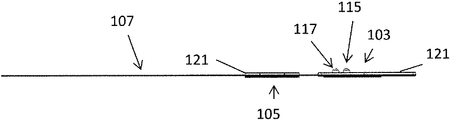
カンチレバー電極はまた、電極アセンブリ、電極パッド、電極システムまたは電極装置とも呼ばれ得、耐久性または使い捨てであり得、概して、神経調節機器に接続し、神経調節機器から対象の皮膚にエネルギー(たとえば電流)を印加して対象の認知状態または他の認知機能を調節する(たとえば鎮静する、鼓舞する、など)ように構成されている。本明細書に記載されるカンチレバー式電極は、神経刺激器が電極(電極アセンブリ)によって体に対して保持されるよう、対象の体に付き、ウェアラブル神経刺激器に接続するように構成されている。本明細書の中で電極および/または神経刺激器を参照して使用される用語「カンチレバー」または「カンチレバー式」とは、概して、神経刺激器の患者と対向する面に対して偏心的であり、一般に、神経刺激器の患者と対向する面および電極アセンブリの外向き側面のいずれかまたは両方の端部領域または縁領域に近い一つまたは複数(たとえば二つ)の位置でウェアラブル神経刺激器に機械的に接続するように構成されている電極を指す。これは一般に、神経刺激器の一つの端部または端部領域を電極(ひいては、ユーザによって装着されているときには、体)に固定された状態に保持するが、もう一方の端部または端部領域をそのように保持しない、一つの端部領域に留められる、神経刺激器と電極ボディとの間の機械的接続を生じさせる。したがって、いくつかの変形において、電極アセンブリへの接続とは反対側の神経刺激器の部分は、電極アセンブリに対して動き得る、すなわち、装置が装着されているとき、ユーザの皮膚に近づき得る、またはユーザの皮膚から離れ得る。したがって、本明細書に記載されるカンチレバー式取り付け構造は、一つの端部領域における取り付けが、電極ボディに機械的に接続されている端部領域に対して限られたヒンジ様動作を可能にするため、神経刺激器の硬いボディが様々な皮膚表面形状およびカーブに合わせて調節することを可能にする恩典を有する。本明細書に記載される電極アセンブリを参照すると、電極アセンブリは、相対的に長い平坦なボディ(たとえば細長いボディ)を有し得、数インチよりも長い(たとえば、第一の電気的接触領域から次のもっとも近い電気的接触領域までで、たとえば2インチよりも長い、3インチよりも長い、4インチよりも長い、5インチよりも長い)長さを有し得;ウェアラブル神経刺激器への接続は、すべて、電極アセンブリの一つの端部領域またはその近くに、たとえば電気的接触領域の一つの上またはそれに隣接して(電気的接触領域の一つから電極アセンブリの反対側面であるが)位置し得る。 A cantilever electrode can also be referred to as an electrode assembly, electrode pad, electrode system or electrode device, and can be durable or disposable and generally connects to a neuromodulation device and energy (eg, current) from the neuromodulation device to the subject's skin. ) To regulate the cognitive state or other cognitive function of the subject (eg, to sedate, inspire, etc.). The cantilevered electrodes described herein are configured to attach to and connect to a wearable neurostimulator so that the neurostimulator is held against the body by an electrode (electrode assembly). . The term “cantilever” or “cantilevered” as used herein with reference to electrodes and / or neurostimulators is generally eccentric with respect to the patient-facing surface of the neurostimulator. In general, the wearable neurostimulator at one or more (eg, two) locations near the end region or edge region of either or both of the patient-facing side of the neurostimulator and the outward side of the electrode assembly Refers to an electrode configured to be mechanically connected. This generally keeps one end or end region of the neurostimulator fixed to the electrode (and thus the body when worn by the user), but the other end or end region. Creates a mechanical connection between the neurostimulator and the electrode body, which is held in one end region, which does not hold so. Thus, in some variations, the portion of the neurostimulator opposite the connection to the electrode assembly can move relative to the electrode assembly, i.e., approach the user's skin when the device is worn, Or it can be away from the user's skin. Thus, the cantilevered mounting structure described herein allows for a limited hinge-like operation with respect to the end region where attachment in one end region is mechanically connected to the electrode body. Thus, it has the benefit of allowing the rigid body of the neurostimulator to adjust to various skin surface shapes and curves. Referring to the electrode assembly described herein, the electrode assembly may have a relatively long flat body (eg, an elongated body) that is longer than a few inches (eg, from a first electrical contact area). Can have a length up to the next closest electrical contact area, eg, longer than 2 inches, longer than 3 inches, longer than 4 inches, longer than 5 inches; connection to a wearable nerve stimulator Are all located at or near one end region of the electrode assembly, for example above or adjacent to one of the electrical contact regions (although from one of the electrical contact regions to the opposite side of the electrode assembly) Can do.
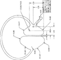
たとえば、本明細書に記載されるものは、対象の頭に装着される電気刺激器と共に使用するための電極装置である。概して、これらの電極装置は、電気刺激器に接続するための二つの電気接続(スナップコネクタなどのような機械的コネクタであってもよい)を一つの端部領域に含む。これらの電気コネクタの位置は中心間で約0.6〜0.9インチであり得る。この距離は、電極装置の異なる活性領域に接続するとき電気的分離を許しながらも、カンチレバー電極が電気刺激器に接続され、次いで対象によって装着されるとき、またカンチレバー電極に対して十分な機械的支持および/または許容差を提供するのに十分であることがわかっている。 For example, what is described herein is an electrode device for use with an electrical stimulator worn on a subject's head. In general, these electrode devices include two electrical connections (which may be mechanical connectors such as snap connectors) for connection to an electrical stimulator in one end region. The location of these electrical connectors can be about 0.6 to 0.9 inches between the centers. This distance allows sufficient electrical separation when connecting to different active areas of the electrode device, but is sufficient mechanical when the cantilever electrode is connected to the electrical stimulator and then worn by the subject and also for the cantilever electrode. It has been found sufficient to provide support and / or tolerance.
本明細書に記載されるカンチレバー電極装置は、一つの端部領域またはその近くで対象の皮膚に電気エネルギーを印加するための第一の活性領域と、第二の端部領域またはその近くで対象の皮膚の別の領域に電気エネルギーを印加するための第二の活性領域とを含む、概して細長く薄いボディである。電気刺激器に接続するための電気コネクタはいずれも、一般に、細長いボディの一つの端部領域またはその近くにある。ボディ上の第一および第二の活性領域は、一般に2インチよりも長い長さの細長い部分によって接続され得る。いくつかの変形において、細長いボディは剛性である、または相対的に硬い(しかし、延性であってもよいし、または成形するために曲げることができる延性領域を含んでもよい)。いくつかの変形において、細長いボディは、たとえば第一の軸(たとえばx軸)には可撓性であるが、第二の軸(たとえばy軸)には可撓性ではなく、捻転され得るような限られた可撓性を有する。たとえば、電極装置の細長いボディは、フレックス回路材料のような材料のシートで形成され得る。 The cantilever electrode device described herein includes a first active region for applying electrical energy to a subject's skin at or near one end region and a target at or near a second end region. A generally elongated and thin body including a second active region for applying electrical energy to another region of the skin. Any electrical connector for connecting to an electrical stimulator is generally at or near one end region of the elongated body. The first and second active regions on the body can be connected by an elongated portion that is generally longer than 2 inches. In some variations, the elongate body is rigid or relatively stiff (but may be ductile or include a ductile region that can be bent to form). In some variations, the elongate body is flexible, eg, on a first axis (eg, x-axis), but not flexible on a second axis (eg, y-axis), so that it can be twisted. Limited flexibility. For example, the elongated body of the electrode device can be formed of a sheet of material such as flex circuit material.
本明細書に使用されるように、ある部品が別の部品の端部領域にあると記載されるとき、第一の部品は、その別の部品の極端にあることに限定されず、その別の部品の絶対的端部または縁に隣接する、またはそれに近いだけでもよいということが理解されよう。たとえば、第一の部品は、その別の部品の縁または絶対的端部からその別の部品の全長の20%以下の範囲内にあり得る。対照的に、ある部品が別の部品の端部または縁にあると記載されるとき、第一の部品は、その別の部品の絶対的端部もしくは縁またはそれにすぐ隣接するところにあり得る。 As used herein, when a part is described as being in the end region of another part, the first part is not limited to being at the extreme of that other part, It will be understood that it may only be adjacent to or close to the absolute end or edge of the part. For example, the first part may be within 20% or less of the total length of the other part from the edge or absolute end of the other part. In contrast, when a part is described as being at the end or edge of another part, the first part can be at the absolute end or edge of that other part or immediately adjacent thereto.
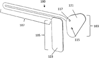
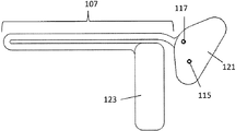
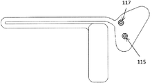
たとえば、電極装置は、前面側および背面側を有する第一の電極部分;対象の皮膚にエネルギーを送達するように構成されている、前面側の第一の活性領域;背面側から突き出て延びる、第一の活性領域と電気的に連絡する第一のコネクタ;背面側から突き出て延びる第二のコネクタであって、第一および第二のコネクタが中心間で約0.7〜約0.8インチ離間している、第二のコネクタ;第一の電極部分と第二の電極部分との間に少なくとも2インチ延びる細長いボディ領域によって第一の電極部分から切り離された第二の電極部分;および第二のコネクタと電気的に連絡し、かつ対象の皮膚にエネルギーを印加するように構成されている、第二の電極部分の前面側の第二の活性領域を含み得る。 For example, the electrode device includes a first electrode portion having a front side and a back side; a first active region on the front side configured to deliver energy to the subject's skin; A first connector in electrical communication with the first active region; a second connector extending from the rear side, the first and second connectors being spaced from the center about 0.7 to about 0.8 inches A second connector; a second electrode portion separated from the first electrode portion by an elongated body region extending at least 2 inches between the first electrode portion and the second electrode portion; and a second connector A second active region on the front side of the second electrode portion that is in electrical communication with and configured to apply energy to the subject's skin.
本明細書の中で使用される電極部分とは、たとえばカソードまたはアノード領域として構成されている電気活性領域を一面に含む電極アセンブリの領域を指し得、また、たとえば、電気活性領域をユーザの皮膚に対して保持するための接着剤を含む、周囲の非電気活性領域をも含み得る。電気活性領域は、以下に詳細に説明するように、すべていっしょに、またはサブセットとして電気的に活性化され得る複数のサブ領域を含み得る。電極部分はまた、電気活性領域を有する面から反対側の面を含み得;いくつかの例において、この反対側面は、ウェアラブル神経刺激器との電気的および/または機械的接触を形成するための一つまたは複数の接点を含み得る。他の電極部分は、接点を含まなくてもよく、電極アセンブリ上の他の位置に存在する接点に接続され得る(たとえば電気トレースによって)。電極部分は、たとえば基材の端部領域における、電極アセンブリを形成する基材のサブ領域であってもよい。いくつかの変形において、電極部分は、電極アセンブリの個別領域(二つ以上のそのような電極部分を含み得る)である。 As used herein, an electrode portion can refer to a region of an electrode assembly that includes an electroactive region configured, for example, as a cathode or anode region, and also includes, for example, an electroactive region on a user's skin. It may also include a surrounding non-electroactive region that includes an adhesive to hold against. The electroactive region can include multiple subregions that can be electrically activated all together or as a subset, as described in detail below. The electrode portion may also include a surface opposite the surface having the electroactive region; in some examples, the opposite surface is for making electrical and / or mechanical contact with the wearable nerve stimulator. One or more contacts may be included. Other electrode portions may not include contacts and may be connected (eg, by electrical traces) to contacts present at other locations on the electrode assembly. The electrode portion may be a sub-region of the substrate that forms the electrode assembly, for example in an end region of the substrate. In some variations, the electrode portions are discrete regions of the electrode assembly (which may include two or more such electrode portions).
前述のように、第一および第二の導体は一般に、装置を電気刺激器に電気的に接続するように構成されている。たとえば、第一および第二のコネクタはスナップコネクタであり得る。第一および第二のコネクタが一体化されて、神経刺激器と電極装置との間に少なくとも二つの別々の導電路を有する単一のコネクタユニットを形成してもよい。コネクタは、電気刺激器への機械的接続および電気的接続を提供し得る。コネクタは、カンチレバー電極装置を電気アプリケータに対して保持(または保持することを支援)し得る。代替的または追加的に、電極装置は、電極装置を電気刺激器に固定するように構成された機械的ファスナを含み得る。いくつかの変形において、コネクタは、電極装置を電気刺激器に固定するのに十分である。いくつかの変形においては、カンチレバー電極装置を電気アプリケータに固定するために、電極装置と電気アプリケータ(たとえば神経刺激器)との間に接着剤が使用されてもよい。たとえば、装置は、電極装置を電気刺激器に対して保持するように構成された第一の平坦な電極部分の背面側に接着剤を含み得る。いくつかの変形においては、電極装置を神経刺激器に結合するために、機械的コネクタの代わりに、またはそれに加えて、磁石および強磁性体が使用される。概して、第一および第二のコネクタは、電極装置を電気刺激器に電気的に接続するように構成されている。 As described above, the first and second conductors are generally configured to electrically connect the device to the electrical stimulator. For example, the first and second connectors can be snap connectors. The first and second connectors may be integrated to form a single connector unit having at least two separate conductive paths between the neurostimulator and the electrode device. The connector may provide mechanical and electrical connection to the electrical stimulator. The connector may hold (or assist in holding) the cantilever electrode device relative to the electrical applicator. Alternatively or additionally, the electrode device may include a mechanical fastener configured to secure the electrode device to the electrical stimulator. In some variations, the connector is sufficient to secure the electrode device to the electrical stimulator. In some variations, an adhesive may be used between the electrode device and the electrical applicator (eg, neurostimulator) to secure the cantilever electrode device to the electrical applicator. For example, the device may include an adhesive on the back side of a first flat electrode portion that is configured to hold the electrode device against the electrical stimulator. In some variations, magnets and ferromagnets are used in place of or in addition to mechanical connectors to couple the electrode device to the neurostimulator. Generally, the first and second connectors are configured to electrically connect the electrode device to the electrical stimulator.
上述したように、第一および第二の電極部分(および第一および第二の活性領域)の間の細長いボディ領域は、第一の方向には可撓性であり得るが、第一の方向に対して垂直な方向には可撓性ではない。たとえば、細長いボディ領域は、フレックス回路材料のような材料の条片で形成され得る。フレックス回路材料の例は周知であり、たとえば、ポリマー、たとえばポリエステル(PET)、ポリイミド(PI)、ポリエチレンナフタレート(PEN)、ポリエーテルイミド(PEI)、様々なフルオロポリマー(FEP)およびコポリマーを含む。 As described above, the elongated body region between the first and second electrode portions (and the first and second active regions) can be flexible in the first direction, but the first direction It is not flexible in the direction perpendicular to. For example, the elongated body region may be formed of a strip of material such as flex circuit material. Examples of flex circuit materials are well known and include, for example, polymers such as polyester (PET), polyimide (PI), polyethylene naphthalate (PEN), polyetherimide (PEI), various fluoropolymers (FEP) and copolymers .
概して、電極装置は実質的に平坦であり得る。たとえば、電極装置の厚さは、5mm未満、4mm未満、3mm未満、1mm未満、0.9mm未満、0.8mm未満、0.7mm未満、0.6mm未満などである全厚さ(たとえば、基材と、基材に印刷、シルクスクリーン印刷または他のやり方で接着された層との厚さ)を有し得、平面(曲がっていてもカーブしていてもよい)に延び得る。コネクタは、この全厚さから突き出て延び得る。加えて、電極部分はこの全厚さの上/下に延びてもよい。 In general, the electrode device can be substantially flat. For example, the thickness of the electrode device is less than 5 mm, less than 4 mm, less than 3 mm, less than 1 mm, less than 0.9 mm, less than 0.8 mm, less than 0.7 mm, less than 0.6 mm, etc. (Thickness with layers printed on the material, silk screen printing or otherwise adhered) and may extend in a plane (which may be curved or curved). The connector can extend out of this total thickness. In addition, the electrode portion may extend above / below this full thickness.
本明細書に記載される変形のいずれにおいても、電極装置は、第一の活性領域および/または第二の活性領域の上に導電性ゲルを含み得る。導電性ゲルは、活性領域を対象の皮膚に固定するために、接着性であってもよいし、および/またはさらなる接着剤によって包囲されてもよい。たとえば、電極装置は、第一の電極部分の前面側および/または第二の電極部分の前面側に接着剤を含み得る。 In any of the variations described herein, the electrode device can include a conductive gel over the first active region and / or the second active region. The conductive gel may be adhesive and / or surrounded by additional adhesive to secure the active area to the subject's skin. For example, the electrode device may include an adhesive on the front side of the first electrode portion and / or the front side of the second electrode portion.
いくつかの変形において、電極装置はフォーム領域を含む。たとえば、装置は、第一の電極部分上にフォームを含み得る。フォームは、第一の活性領域を対象の皮膚に対して快適に当てることに役立ち得、また、神経刺激器に結合された電極装置が、人によって異なり得る対象の体のカーブした部分に、よりぴったり適合するよう、装置と対象の皮膚との間に間隔を提供し得る。 In some variations, the electrode device includes a foam region. For example, the device can include a foam on the first electrode portion. The foam can help to comfortably apply the first active area to the subject's skin, and the electrode device coupled to the neurostimulator is more sensitive to the curved portion of the subject's body that can vary from person to person. A spacing may be provided between the device and the subject's skin for a close fit.
第一および第二のコネクタはいずれも、一般に、第一の電極部分の背面側で互いに隣接するが、上述したように、許容差および支持を許すのに十分な距離だけ離間している。いくつかの変形において、第一のコネクタは第一の活性領域の背後にあり、第二のコネクタは第一の活性領域の背後にはない。 Both the first and second connectors are generally adjacent to each other on the back side of the first electrode portion, but are separated by a distance sufficient to allow tolerances and support, as described above. In some variations, the first connector is behind the first active area and the second connector is not behind the first active area.
第一の電極部分の第一の活性領域は第一の電極部分上に偏心的に配置され得る。 The first active region of the first electrode portion can be eccentrically disposed on the first electrode portion.
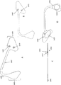
装置は概して、前面側および背面側を有する薄く(たとえば平坦な)可撓性の細長いボディを含み得、第一の電極部分が可撓性の細長いボディの第一の端部領域またはその近くにあり、第二の平坦な電極部分が可撓性の細長いボディの第二の端部領域またはその近くにあり、細長いボディ領域が第一および第二の活性領域の間に延びる。細長いボディは2インチよりも長い長さ(たとえば、3インチよりも大きな長さ、4インチよりも長い長さ、など)であり得る。いくつかの変形において、細長いボディは、カーブしている、または曲がっている(撓んでいないとき)。たとえば、細長いボディは、その中に曲りまたは他の平面外構造もしくは剛性を有し得る。 The apparatus may generally include a thin (eg, flat) flexible elongate body having a front side and a back side, wherein the first electrode portion is at or near the first end region of the flexible elongate body. A second flat electrode portion is at or near the second end region of the flexible elongate body, and the elongate body region extends between the first and second active regions. The elongate body can be longer than 2 inches (eg, longer than 3 inches, longer than 4 inches, etc.). In some variations, the elongated body is curved or bent (when not deflected). For example, the elongate body may have a bend or other out-of-plane structure or stiffness therein.
いくつかの変形において、細長いボディ領域は、可撓性の細長い基材上に電気トレースを含み得る。電気トレースは、印刷または他のやり方で基材に適用(またはその中に埋め込み)され得る。たとえば、トレースは、導電性インクを使用してフレキソ印刷、シルクスクリーン印刷またはレーザ印刷され得る。 In some variations, the elongated body region can include electrical traces on a flexible elongated substrate. The electrical trace can be applied to (or embedded in) the substrate by printing or otherwise. For example, the traces can be flexographically printed, silkscreen printed or laser printed using conductive ink.
電気トレースは、第二のコネクタと第二の電極部分の第二の活性領域との間の電気接続を提供し得る。 The electrical trace may provide an electrical connection between the second connector and the second active area of the second electrode portion.
対象の頭に装着される電気刺激器と共に使用するための電極装置は、前面側および背面側を有する平坦で可撓性の細長いボディ;細長いボディの第一の端部領域またはその近くにある第一の電極部分;エネルギーを対象の皮膚に送達するように構成されている、第一の電極部分の前面側の第一の活性領域;第一の活性領域と電気的に連絡する、第一の電極部分の背面側の背後から突き出て延びる第一のコネクタ;第一の電極部分の背面側から突き出て延びる第二のコネクタ;第一の電極部分から少なくとも2インチ離間している、細長いボディの第二の端部領域またはその近くにある第二の電極部分;および第二のコネクタと電気的に連絡し、かつエネルギーを対象の皮膚に送達するように構成されている、第二の電極部分の前面側の第二の活性領域を含み得、ここで、第一および第二のコネクタは、装置を電気刺激器に電気的に接続するように構成されている。 An electrode device for use with an electrical stimulator mounted on a subject's head comprises a flat, flexible elongated body having a front side and a back side; a first end region at or near a first end region of the elongated body A first active region on the front side of the first electrode portion configured to deliver energy to the skin of the subject; a first active region in electrical communication with the first active region; A first connector extending from behind the back side of the electrode portion; a second connector extending from the back side of the first electrode portion; an elongated body spaced at least 2 inches from the first electrode portion A second electrode portion at or near the second end region; and a second electrode portion in electrical communication with the second connector and configured to deliver energy to the subject's skin Second life on the front side of Where the first and second connectors are configured to electrically connect the device to the electrical stimulator.
上述したように、第一および第二のコネクタは、装置を電気刺激器に電気的に接続するように構成されており、たとえば、スナップコネクタであり得る。 As described above, the first and second connectors are configured to electrically connect the device to the electrical stimulator and may be, for example, snap connectors.
上述したように、電極装置は、導電性ゲル(たとえば、第一の活性領域および/または第二の活性領域の上)、第一の電極部分の前面側および第二の電極部分の前面側の接着剤、第一の平坦な電極部分上のフォームなどを含み得る。本明細書に記載される電極装置のいずれにおいても、第一および第二のコネクタは約0.6〜約0.9インチ(たとえば約0.7〜約0.8インチ、約0.72インチなど)離間し得る。 As described above, the electrode device comprises a conductive gel (eg, over the first active region and / or the second active region), the front side of the first electrode portion and the front side of the second electrode portion. An adhesive, foam on the first flat electrode portion, and the like may be included. In any of the electrode devices described herein, the first and second connectors can be spaced from about 0.6 to about 0.9 inches (eg, about 0.7 to about 0.8 inches, about 0.72 inches, etc.).
対象の頭に装着される電気刺激器と共に使用するための可撓的に接続される電極装置は、前面側および背面側を有する平坦で可撓性の細長いボディ;細長いボディの第一の端部領域における第一の電極部分;エネルギーを対象の皮膚に送達するように構成されている、第一の電極部分の前面側の第一の活性領域;第一の活性領域と電気的に連絡する、第一の活性領域の背後で第一の電極部分の背面側から突き出て延びる第一のコネクタ;第一の電極部分の背面側の背後から突き出て延びる第二のコネクタであって、第一のコネクタおよび第二のコネクタが約0.7〜約0.8インチ離間している第二のコネクタ;細長いボディの第二の端部領域における第二の電極部分;および第二のコネクタと電気的に連絡し、エネルギーを対象の皮膚に送達するように構成されている、第二の電極部分の前面側の第二の活性領域を含み得、第一および第二のスナップコネクタは、装置を電気刺激器に電気的に接続するように構成されている。 A flexibly connected electrode device for use with an electrical stimulator mounted on a subject's head comprises a flat, flexible elongate body having a front side and a back side; a first end of the elongate body A first electrode portion in the region; a first active region on the front side of the first electrode portion configured to deliver energy to the subject's skin; in electrical communication with the first active region; A first connector extending from the back side of the first electrode portion behind the first active region; a second connector extending from the back side of the first electrode portion; A second connector in which the connector and the second connector are spaced from about 0.7 to about 0.8 inches; a second electrode portion in the second end region of the elongated body; and in electrical communication with the second connector; Deliver energy to the target skin Configured to include a second active region on the front side of the second electrode portion, wherein the first and second snap connectors are configured to electrically connect the device to the electrical stimulator Yes.
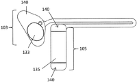
同じく本明細書に記載されるものは、電極装置を対象に適用する方法およびそのような電極装置のいずれかを使用して電気刺激を対象に印加する方法である。たとえば、ウェアラブル電気刺激器に結合された平坦な細長い電極装置を使用して電気刺激を対象の頭部(または頭頸部)に印加する方法は、第一の電気コネクタをウェアラブル電気シミュレータの下面側の第一のレセプタクルに挿入し、電極装置の第二の電気コネクタをウェアラブル電気刺激器の下面側の第二のレセプタクルに挿入することにより、電極装置の第一および第二の電気コネクタをウェアラブル電気刺激器に接続する工程であって、第一および第二の電気コネクタが電極装置の第一の活性領域の背面側から突き出て延びる、工程;電気刺激器に結合された電極装置を対象の頭に接着的に固定して、電極装置の前面側の第一の活性領域が対象の頭と電気的に接触するようにする工程;および電極装置の前面側の第二の活性領域を対象の頭または首上の第二の位置で接着的に固定する工程を含み得、第二の活性領域は平坦で可撓性の細長いボディを介して第一の電極部分から切り離され(ただし、第一および第二の活性領域は同じ基材上にあり得る)、第二の活性領域は第二の電気コネクタに電気的に接続されてる。方法はまた、第一の活性領域の背面側をウェアラブル電気刺激器の下面側に接着的に固定する工程を含み得る。 Also described herein are a method of applying an electrode device to a subject and a method of applying electrical stimulation to a subject using any such electrode device. For example, a method of applying electrical stimulation to a subject's head (or head and neck) using a flat elongated electrode device coupled to a wearable electrical stimulator includes connecting a first electrical connector to the underside of the wearable electrical simulator. Wearable electrical stimulation of the first and second electrical connectors of the electrode device by inserting into the first receptacle and inserting the second electrical connector of the electrode device into the second receptacle on the underside of the wearable electrical stimulator A first and second electrical connector projecting from the back side of the first active area of the electrode device; the electrode device coupled to the electrical stimulator on the subject's head Adhesively securing the first active region on the front side of the electrode device in electrical contact with the subject's head; and a second active region on the front side of the electrode device; Adhesively securing at a second location on the elephant's head or neck, wherein the second active region is separated from the first electrode portion via a flat, flexible elongated body (however, The first and second active areas can be on the same substrate), and the second active area is electrically connected to the second electrical connector. The method may also include the step of adhesively fixing the back side of the first active region to the bottom side of the wearable electrical stimulator.
方法はまた、ウェアラブル電気刺激器からのエネルギーを第一および第二の活性領域の間に印加する工程を含み得る。たとえば、方法は、少なくとも3mAのピーク電流、640Hzを超える周波数および約10%よりも大きいデューティサイクルを有する、ウェアラブル電気シミュレータからの電流を印加する工程を含み得る。たとえば、方法は、たとえば、約5mA〜約25mAの波形アンサンブルの最大値、約750Hz〜15kHzの最大卓越周波数および約20〜70%のデューティサイクルなどを有する、少なくとも5mA以上の電流を印加する工程を含み得、波形は二相性かつ非対称性であり、いくつかの変形において、反復波形内に一過性の「短絡」または放電を含む。 The method can also include applying energy from the wearable electrical stimulator between the first and second active regions. For example, the method can include applying a current from a wearable electrical simulator having a peak current of at least 3 mA, a frequency greater than 640 Hz, and a duty cycle greater than about 10%. For example, the method comprises applying a current of at least 5 mA having, for example, a maximum waveform ensemble of about 5 mA to about 25 mA, a maximum dominant frequency of about 750 Hz to 15 kHz, a duty cycle of about 20 to 70%, etc. The waveform may be biphasic and asymmetric, and in some variations includes a transient “short circuit” or discharge within the repetitive waveform.
電気刺激器に結合された電極装置を接着的に固定する工程は、第一の活性領域およびウェアラブル電気刺激器を対象の側頭に固定する工程を含み得る。たとえば、活性領域が横向きおよび/または対象の眼よりもわずかに上にある状態で。いくつかの変形において、第二の活性領域を接着的に固定する工程は、第二の活性領域を対象の首または対象の耳の後の部位(たとえば乳様突起部位、たとえば乳様突起の上または近く)に固定する工程を含む。第一および第二の電気コネクタを接続する工程は、第一の電気コネクタが第二の第一の電気コネクタから約0.7〜0.8インチである、第一および第二の電気コネクタを接続する工程を含み得る。 Adhesively securing the electrode device coupled to the electrical stimulator may include securing the first active region and the wearable electrical stimulator to the subject's temporal region. For example, with the active area lying sideways and / or slightly above the subject's eye. In some variations, the step of adhesively securing the second active region comprises attaching the second active region to a site behind the subject's neck or ear (eg, on the mastoid site, eg, the mastoid). Or near). Connecting the first and second electrical connectors comprises connecting the first and second electrical connectors, wherein the first electrical connector is about 0.7 to 0.8 inches from the second first electrical connector. May be included.
概して、第二の活性領域を接着的に固定する工程は、平坦で可撓性の細長いボディを対象の頭の周囲に曲げて、第二の活性領域を対象の頭または首(たとえば対象の首の背面または対象の耳の後、または乳様突起部位もしくはその近く)に配置する工程を含む。 In general, the step of adhesively securing the second active area involves bending a flat, flexible elongate body around the subject's head to place the second active area on the subject's head or neck (eg, the subject's neck). Or behind the ear of the subject or at or near the mastoid site.
電極装置を装着する方法は、第一の電気コネクタをウェアラブル電気シミュレータの下面側の第一のレセプタクルに挿入し、電極装置の第二の電気コネクタをウェアラブル電気刺激器の下面側の第二のレセプタクルに挿入することにより、電極装置の第一および第二の電気コネクタをウェアラブル電気刺激器に接続する工程であって、第一および第二の電気コネクタが電極装置の第一の活性領域の背面側から突き出て延びる、工程;電気刺激器に結合された電極装置を、電極装置の前面側の第一の活性領域が対象の頭と電気的に接触するよう、対象の頭に接着的に固定する工程;および電極装置の前面側の第二の活性領域を対象の頭または首上の第二の位置で接着的に固定する工程を含み得、第二の活性領域は、第二の活性領域が第二の電気コネクタに電気的に接続されるよう、平坦で可撓性の細長いボディを介して第一の活性領域に接続される。 The method of mounting the electrode device includes inserting a first electrical connector into a first receptacle on the lower surface side of the wearable electrical simulator, and inserting a second electrical connector of the electrode device into a second receptacle on the lower surface side of the wearable electrical stimulator. Connecting the first and second electrical connectors of the electrode device to the wearable electrical stimulator by inserting into the back side of the first active region of the electrode device Extending from the step; adhesively fixing an electrode device coupled to the electrical stimulator to the subject's head such that the first active region on the front side of the electrode device is in electrical contact with the subject's head And adhesively securing a second active area on the front side of the electrode device at a second location on the subject's head or neck, wherein the second active area is Second electricity To be electrically connected to the connector, it is connected to the first active region through an elongated body flexible flat.
いくつかの変形においては、二つ以上の電気コネクタが神経刺激器上のマルチピンレセプタクルに接続される。たとえば、二つ以上の電気コネクタを有する一つの機械的コネクタを使用し得る。 In some variations, two or more electrical connectors are connected to a multi-pin receptacle on the neurostimulator. For example, a single mechanical connector having two or more electrical connectors may be used.
方法はまた、第一の活性領域の背面側をウェアラブル電気刺激器の下面側に接着的に固定する工程を含み得る。 The method may also include the step of adhesively fixing the back side of the first active region to the bottom side of the wearable electrical stimulator.
本発明の新規な特徴は以下の特許請求の範囲の中で詳細に述べられる。本発明の原理が利用されている例示的な態様を記す以下の詳細な説明および添付図面を参照することにより、本発明の特徴および利点のより良い理解が得られるであろう。 The novel features of the invention are set forth with particularity in the following claims. A better understanding of the features and advantages of the present invention will be obtained by reference to the following detailed description that sets forth illustrative embodiments, in which the principles of the invention are utilized, and the accompanying drawings of which:
詳細な説明
概して、本明細書に記載されるものは、カンチレバー電極装置、それらを含むシステムおよびそれらを装着し、使用して神経刺激/神経調節を対象に送達する方法である。本明細書に記載されるカンチレバー電極装置は、ウェアラブルな軽量の自蔵式神経刺激器(「電気刺激器」)と、刺激が印加される対象の体、特に頭部または頭頸部部位との間でインタフェースとして働き得る。これらのカンチレバー電極装置は、神経刺激器に接続され、対象に直接適用される使い捨て(または半使い捨て)(かつ、リサイクル可能または半リサイクル可能)部品であり得;神経刺激器からのエネルギー(一般には電流)がカンチレバー電極装置によって誘導され、対象に送達される。神経刺激器は小型軽量であり得るが、カンチレバー電極装置は、それを対象の体に固定し、神経刺激器のサイズよりもずっと長い距離だけ離間している体の二つ以上の部位(たとえば側頭、首、胸など)にエネルギーを送達することを可能にし得る。
DETAILED DESCRIPTION Generally, what is described herein is a cantilever electrode device, a system comprising them, and a method of wearing and using them to deliver neural stimulation / nerve modulation to a subject. The cantilever electrode device described herein is a wearable, lightweight self-contained neurostimulator ("electric stimulator") and the body to which a stimulus is applied, particularly the head or head and neck region. Can work as an interface. These cantilever electrode devices can be disposable (or semi-disposable) (and recyclable or semi-recyclable) components that are connected to the neurostimulator and applied directly to the subject; energy from the neurostimulator (typically Current) is induced by the cantilever electrode device and delivered to the subject. Although the neurostimulator can be small and light, the cantilever electrode device secures it to the subject's body and is separated by two or more parts of the body (eg, the sides) that are separated by a distance much longer than the size of the neurostimulator. It may be possible to deliver energy to the head, neck, chest, etc.).
本明細書に記載される電極装置の大部分は、電極アセンブリにカンチレバー式に取り付けられるウェアラブル神経刺激器と共に使用されるように構成されているが、これらの電極アセンブリは、この使用に限定されず、非ウェアラブルまたは部分的ウェアラブルな電気刺激器との使用も見いだし得る。たとえば、ポータブルまたはデスクトップ神経刺激器に接続する一つまたは複数のワイヤを取り付けることにより、神経刺激器が、本明細書に記載される電極のコネクタに結合してもよい。 Although most of the electrode devices described herein are configured for use with wearable nerve stimulators that are cantileveredly attached to the electrode assemblies, these electrode assemblies are not limited to this use. Also, use with non-wearable or partially wearable electrical stimulators may be found. For example, the neurostimulator may be coupled to the electrode connector described herein by attaching one or more wires that connect to a portable or desktop neurostimulator.
システム説明
概して、本明細書に記載される神経刺激システムは、少なくとも二つの部品:(1)頭に装着されるように構成されている軽量のウェアラブル神経刺激機器(神経刺激器);および(2)消耗性/使い捨て電極アセンブリを含み得る。電極アセンブリの複数の構成(たとえば形状)があり得、本明細書の中でさらに詳細に説明するように、電極アセンブリは概して、可撓性材料(「フレックス回路」材料)上に形成され、神経刺激器に機械的かつ電気的に接続され得る。いくつかの変形においては、第三の部品が、神経刺激器から切り離されているが、神経刺激器と通信する制御装置であり得る。たとえば、いくつかの変形において、制御装置は、神経刺激器とワイヤレスに通信するユーザ機器であり得る。いくつかの変形において、制御装置は、命令を送り、神経刺激器と双方向通信信号を交換するアプリケーションによって制御されるモバイル電気通信機器(たとえばスマートフォンまたはタブレット)である。たとえば、制御装置は、ソフトウェア、ハードウェアまたはファームウェアであり得、ユーザによってダウンロードされてワイヤレス接続可能な(すなわちBluetoothによって)機器(たとえばハンドヘルド型機器、たとえばスマートフォンまたはタブレット)上で作動して、ユーザが、神経刺激器によって送達される波形を選択すること(本明細書に記載されるように、ユーザの認知状態を調節するための、送達される神経刺激のリアルタイム調節を含む)を許すことができるアプリケーションを含み得る。
System Description In general, the nerve stimulation system described herein includes at least two parts: (1) a lightweight wearable nerve stimulation device (neural stimulator) configured to be worn on the head; and (2 ) It may include a consumable / disposable electrode assembly. There may be multiple configurations (eg, shapes) of the electrode assembly, and as described in more detail herein, the electrode assembly is generally formed on a flexible material (a “flex circuit” material) It can be mechanically and electrically connected to the stimulator. In some variations, the third component is disconnected from the neurostimulator, but may be a controller that communicates with the neurostimulator. For example, in some variations, the controller may be a user equipment that communicates wirelessly with the neurostimulator. In some variations, the controller is a mobile telecommunications device (eg, a smartphone or tablet) that is controlled by an application that sends commands and exchanges bidirectional communication signals with the neurostimulator. For example, the control device can be software, hardware or firmware that runs on a device that can be downloaded and wirelessly connected (ie, via Bluetooth) by the user (eg, a handheld device, eg, a smartphone or tablet) and Select the waveform delivered by the neural stimulator (including real-time adjustment of the delivered neural stimulation to adjust the user's cognitive state as described herein) Can include applications.
たとえば、システムは、「穏やかな」精神状態または「活気ある」精神状態を誘発するように作動させることができる。活気が増した状態を誘発するためのシステムの作動は、代替的に、集中力および注意力を高めること;警戒心を高めること;集中力および/または注意力を高めること;覚醒を高めること;自覚的活力感を高めること;客観的生理学的活気レベルを高めること;意欲を高めること;生理学的覚醒を高めること;および対象の胸部に身体的温熱感を誘発することの、一つまたは複数として表すことができる。穏やかな、または弛緩した精神状態を増強する状態を誘発するためのシステムの作動は、代替的に、TESセッションを開始してから約5分以内の鎮静状態;気楽な精神状態;心配のない精神状態;睡眠導入;寝つきをよくすること;ゆっくりした時間経過の知覚;筋弛緩;集中力増強;注意散漫の抑止;認知明晰さの増大;感覚明晰さの増大;解離状態;軽い陶酔感;幸福状態;弛緩状態;聴覚および視覚経験の享楽の増強;生理学的覚醒の低下;情緒または他のストレス要因に対応する能力の増大;視床下部下垂体副腎軸の活動の変化に伴う精神生理学的覚醒の低下;ストレス、不安および精神機能不全のバイオマーカの減少;不安緩解;精神明晰状態;身体能力の向上;ストレスに対する反発;末梢部弛緩の身体的感覚;および心拍の知覚の、一つまたは複数として表すことができる。 For example, the system can be operated to induce a “mild” mental state or a “lively” mental state. Actuation of the system to induce a vibrant state may alternatively increase concentration and attention; increase alertness; increase concentration and / or attention; increase alertness; As one or more of enhancing subjective vitality; increasing objective physiological vitality levels; increasing motivation; increasing physiological arousal; and inducing physical thermal sensation in the subject's chest Can be represented. The activation of the system to induce a state that enhances a calm or relaxed mental state can alternatively be a sedation within about 5 minutes of initiating a TES session; an easy mental state; State; Sleep induction; Improve sleep; Perception of slow time course; Muscle relaxation; Concentration enhancement; Deterrence of distraction; Increased cognitive clarity; Increased sense clarity; Dissociation state; Mild euphoria; Happiness State; relaxed state; enhanced enjoyment of hearing and visual experience; decreased physiological arousal; increased ability to respond to emotional or other stressors; psychophysiological arousal associated with changes in hypothalamic-pituitary adrenal axis activity Decreased; decreased biomarkers of stress, anxiety and mental dysfunction; anxiety relief; mental clarity; improved physical ability; repulsion to stress; physical sensation of peripheral relaxation; , Can be represented as one or more.
たとえば、活気を誘発するためには、電極装置をユーザの側頭およびユーザの耳の後(たとえば乳様突起部位)に取り付け得る。鎮静を誘発するためには、電極をユーザの側頭およびユーザの首の後に取り付け得る。いずれの例においても、神経刺激器は、反復波形特徴を有し、異なる「ブロック」で構成されるアンサンブル波形を約5〜30分(またはより長く)印加し得;波形アンサンブルは、異なるブロックの間に遷移領域を含み得る。概して、波形ブロックの少なくともいくつか(いくつかの変形においては、その大部分または全部)は概して、>5mA(たとえば、5mA〜40mA、5mA〜30mA、5mA〜22mAなど)の電流振幅および>750Hz(たとえば、750Hz〜25kHz、750Hz〜20kHz、750Hz〜15kHzなど)の周波数を有し、電流は一般に二相性であり、電荷不均衡状態にあり、10〜99%(たとえば、20〜95%、30〜80%、30〜60%など)のデューティサイクルを有する。これらの特徴の一つまたは複数は、刺激中、数秒から数分ごとの時間スケールで変化させ得る。 For example, to induce vigor, an electrode device can be attached to the user's temporal region and behind the user's ear (eg, a mastoid site). To induce sedation, electrodes can be attached after the user's temporal and user's neck. In either example, the neurostimulator may apply an ensemble waveform that has repetitive waveform features and consists of different “blocks” for about 5 to 30 minutes (or longer); There may be transition regions in between. Generally, at least some of the waveform blocks (most or all in some variations) generally have a current amplitude of> 5 mA (eg, 5 mA to 40 mA, 5 mA to 30 mA, 5 mA to 22 mA, etc.) and> 750 Hz ( For example, having a frequency of 750 Hz to 25 kHz, 750 Hz to 20 kHz, 750 Hz to 15 kHz, etc., the current is generally biphasic, in charge imbalance, and 10 to 99% (eg, 20 to 95%, 30 to 80%, 30-60% etc.). One or more of these features may change on a time scale from seconds to minutes during stimulation.
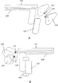
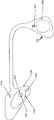
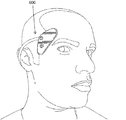
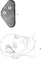
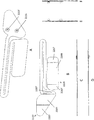
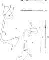
システムは、装着されたとき、図8Aに示すシステムに類似し得、図示するように、対象の頭および/または首の二つの位置(点または部位)に取り付けられる電極アセンブリと、電極アセンブリに取り付けられた神経刺激器とを有し得;いくつかの変形においては、刺激の印加を協調させるための別個の制御装置が取り付けられてもよい。 The system, when worn, may be similar to the system shown in FIG. 8A, as shown, attached to the subject's head and / or neck at two locations (points or sites) and attached to the electrode assembly In some variations, separate controllers may be attached to coordinate the application of stimuli.
本明細書の中でさらに詳細に説明するように、神経刺激器は軽量(たとえば、30g未満、25g未満、20g未満、18g未満、15g未満など)かつ自蔵式であり、たとえば、回路、電源およびワイヤレス通信部品、たとえば蓄電池および充電回路、Bluetoothチップおよびアンテナ、マイクロコントローラ、10秒から数十分の持続期間で波形を送達するように構成された電流源を収容し得る。神経刺激器はまた、安全回路を含み得る。神経刺激器はまた、電極が取り付けられていると判断し、それがどのような「種類」の電極であるのかを決定する(すなわち、鎮静モード用または活気モード用;または製造のバッチおよび/または起源を示す)ための回路を含み得る。図7A〜7Fおよび8Bは神経刺激器の一つの変形を示す。 As described in further detail herein, the neurostimulator is lightweight (eg, less than 30 g, less than 25 g, less than 20 g, less than 18 g, less than 15 g, etc.) and self-contained, eg, circuit, power supply And wireless communication components such as batteries and charging circuits, Bluetooth chips and antennas, microcontrollers, current sources configured to deliver waveforms in durations from 10 seconds to tens of minutes. The neurostimulator may also include a safety circuit. The neurostimulator also determines that the electrode is attached and determines what “type” of electrode it is (ie, for sedation mode or liveness mode; or batch of production and / or Circuitry for indicating the origin). Figures 7A-7F and 8B show one variation of the neurostimulator.
神経刺激器は、対象の右側頭/額区域またはその近くにフィットし、それに適合し得るように成形され得る。本明細書の中でさらに詳細に説明するように、電極アセンブリは、たとえば、神経刺激器の下面側の一つまたは複数(たとえば二つ)のコネクタ、たとえばスナップレシーバにスナップ嵌めすることにより、神経刺激器に機械的および/または電気的に接続し得る。したがって、いくつかの変形において、神経刺激器は、電極アセンブリによって対象の(ユーザの)頭に保持され得;電極アセンブリは、ユーザの頭および/または首に接着的に接続されて、ユーザの所望の部位と電気的接触を形成し得、神経刺激器は、たとえば接着的および/または電気的に電極アセンブリに接続され得る。以下に説明するように、神経刺激器と電極アセンブリとの間のコネクタは、神経刺激器が、接続を断つことなく、電極アセンブリ、ひいてはユーザの頭/首にしっかりと接続されることを許しながらもシステムが多様な体形に装着されることを許す、特定かつ所定の位置に配置され得る。 The neurostimulator may be shaped to fit and fit at or near the subject's right temporal / forehead area. As described in further detail herein, the electrode assembly may be configured to snap into, for example, one or more (eg, two) connectors on the underside of the neurostimulator, eg, a snap receiver. It can be mechanically and / or electrically connected to the stimulator. Thus, in some variations, the neurostimulator can be held on the subject's (user's) head by an electrode assembly; the electrode assembly is adhesively connected to the user's head and / or neck to provide the user's desired The nerve stimulator may be connected to the electrode assembly, eg, adhesively and / or electrically. As described below, the connector between the neurostimulator and the electrode assembly allows the neurostimulator to be securely connected to the electrode assembly and thus the user's head / neck without breaking the connection. Can also be placed in specific and predetermined locations that allow the system to be worn in a variety of body shapes.
以下、電極アセンブリを特定の例および変形と共に詳細に説明する。特に、本明細書に記載されるものは、薄く(たとえば、概して、薄い電極アセンブリから突き出て延び得るコネクタの厚さを含み得ない、厚さ4mm未満、3mm未満、2mm未満、1mm未満など)、可撓性であり、かつ平坦であり得る(たとえば平面に形成された)電極アセンブリである。たとえば、電極アセンブリは、フレックス材料、たとえばフレックス回路を印刷するために使用される材料に印刷され得る。使用中、電極アセンブリは、頭の周囲に巻かれて少なくとも二つの位置(たとえば、側頭と首の後および/または耳の後)で頭と接触することができる。電極アセンブリは、他の点では平坦/平面的な面から突き出て延びて電極アセンブリの活性領域を神経刺激器に接続するコネクタ(電気的および/または機械的)を含み得る。たとえば、神経刺激器は、電極アセンブリの前面から延びる一つまたは複数のスナップによって機械的かつ電気的に接続され得る。いくつかの例において、一つのスナップが、活性領域をユーザの頭に接着するための接着剤によって包囲される第一の活性電極領域(アノードまたはカソード領域)に接続する。電極アセンブリの別個の部分における第二の電極領域(アノードまたはカソード)がもう一方のコネクタに電気的に接続され得る。たとえば、第二の電極領域は、対象の耳の後の乳様突起骨上の部位(活気用電極配置)または髪の生え際でユーザの首を横切る部位、たとえば首の中心線近くの部位(鎮静用電極配置)のいずれかにフィットするように適合され得る。 The electrode assembly is described in detail below with specific examples and variations. In particular, what is described herein is thin (eg, generally may not include connector thicknesses that can extend out of a thin electrode assembly, less than 4 mm thick, less than 3 mm, less than 2 mm, less than 1 mm, etc.) An electrode assembly that can be flexible and flat (eg, formed in a plane). For example, the electrode assembly can be printed on a flex material, such as a material used to print a flex circuit. In use, the electrode assembly can be wrapped around the head and contact the head in at least two positions (eg, after the temporal and neck and / or behind the ear). The electrode assembly may include a connector (electrical and / or mechanical) that extends out of an otherwise flat / planar surface and connects the active area of the electrode assembly to the neurostimulator. For example, the neurostimulator can be mechanically and electrically connected by one or more snaps extending from the front surface of the electrode assembly. In some examples, one snap connects to a first active electrode region (anode or cathode region) that is surrounded by an adhesive to adhere the active region to the user's head. A second electrode region (anode or cathode) in a separate part of the electrode assembly can be electrically connected to the other connector. For example, the second electrode region may be a site on the mastoid bone behind the subject's ear (live electrode placement) or a site that crosses the user's neck at the hairline, eg, a site near the neck centerline (sedation). The electrode arrangement).
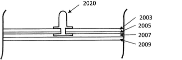
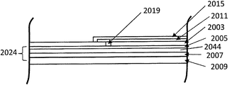
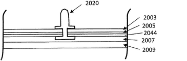
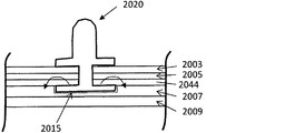
電極装置は、可撓性プラスチック基材(フレックス基材)上にプリントされ得(たとえば、フレキソ印刷、導電性インクを用いるレーザ印刷、シルクスクリーン印刷などにより)、また、皮膚と対向する電極とは反対側に一対のコネクタ(スナップ)を含み得る。アセンブリの背面の電極活性領域は、導体(たとえば銀)の層を含み得、その上に、犠牲層であり、pH緩衝材として働くAg/AgCl層がある。次のヒドロゲル層が、電荷を活性領域に通して皮膚の中に均一に移動させることができるよう、Ag/AgCl電極を覆う。活性電極区域の周囲の電極アセンブリの一部分が、ユーザの皮膚との良好な接触を可能にする接着剤を有してもよい。 The electrode device can be printed on a flexible plastic substrate (flex substrate) (eg, by flexographic printing, laser printing using conductive ink, silk screen printing, etc.), and what is the electrode facing the skin A pair of connectors (snaps) may be included on the opposite side. The electrode active area on the backside of the assembly may include a layer of conductor (eg, silver) on which there is an Ag / AgCl layer that is a sacrificial layer and serves as a pH buffer. The next hydrogel layer covers the Ag / AgCl electrode so that the charge can be transferred uniformly through the active area and into the skin. A portion of the electrode assembly around the active electrode area may have an adhesive that allows good contact with the user's skin.
使用中、ユーザが、神経刺激器と対を成す(たとえばBluetoothによって)制御装置(たとえば、アプリケーションソフトウェア/ファームウェアによって制御されるスマートフォン)と対話し得る。ユーザが、制御装置を操作して動作モード、たとえば、誘発される認知効果のタイプ、たとえば活気モードおよび鎮静モードを選択してもよいし、および/または機器が、装置が取り付けられている電極の構成に基づいて自動的に検出することもできる。ユーザは、たとえば、アンサンブル波形のセットから、どのアンサンブル波形を実行するのかを選択し得る。所望の体感/効果を誘発するための別々の波形(たとえば、「鎮静」または「活気」アンサンブル波形)があってもよい。アンサンブル波形は概して、約3〜90分(たとえば、約3〜60分、約5〜60分、約5〜40分など、約3〜25分など)の長さまたはより長い(たとえば、3分超、5分超、10分超、12分超など)長さであり得る。概して、アンサンブル波形は、特定のパルス化パラメータ、すなわち電流振幅、周波数、デューティサイクル、電荷不均衡、短絡/容量放電などによってセグメントに分割され得、これらのパラメータは、新たなセグメントに移行するとき、規定の時間で変化し得;移行期間は、ブロック特性を切り替えるために含まれ得る。ひとたびユーザがアンサンブル波形を選択すると、それらは神経刺激を開始することができ、ユーザは、フォン(app)を使用して知覚強度を制御または変更し(たとえば知覚強度を上下にダイヤルすることにより)、セッションを一時停止または停止することができる。概して、知覚強度は、ユーザにより、神経刺激器と通信する制御装置(たとえばスマートフォン)上に存在し得る一つまたは複数のボタン、スライド、ダイヤル、トグルなどのような制御を使用して、目標知覚強度(たとえば、目標電流、周波数、デューティサイクル、電荷不均衡および/または短絡/容量放電)の0〜100%の間で増減させることができる。制御装置はまた、ユーザが、所定の応答を誘発させるように設計されている波形構成を活性化(「オンデマンド」)することを許し得る。たとえば、制御機器は、閃光感覚または皮膚感覚強度の知覚認知効果の増強を起動するための一つまたは複数のアイコンを表示するように適合されることもできる。加えて、制御装置は、ユーザが、電極装置および/または神経刺激器を適用するのに役立つためにアイコンを押すことを許すように構成され得る。たとえば、この制御のアクティブ化は、スマートフォンをしてその正面側カメラをアクティブ化させて、ユーザが装置を頭に取り付けるのに役立ち得る。セッションの最中または後、ユーザは、ヘルプスクリーン、プロフィールページ、ソーシャルシェアリングインタフェース(すなわち、自分の経験をツイートする)、セッションに関するフィードバックおよび以前の使用の分析・履歴にアクセスすることができる。概して、システムはまた、制御装置および/または神経刺激器との間および/またはリモートサーバとの間でインターネットを介してデータを受け渡しするように構成され得る。これらのデータは、ユーザ情報、波形データ、ハードウェア機器または電極アセンブリの機能または状態に関する情報などを含み得る。 In use, a user may interact with a control device (eg, a smartphone controlled by application software / firmware) that is paired (eg, via Bluetooth) with a neurostimulator. The user may operate the control device to select an operating mode, for example, the type of cognitive effect to be induced, such as a lively mode and a sedative mode, and / or the device is connected to the electrode to which the device is attached. It can also be detected automatically based on the configuration. The user may select which ensemble waveform to execute from, for example, a set of ensemble waveforms. There may be separate waveforms (eg, “sedation” or “liveness” ensemble waveforms) to induce the desired experience / effect. Ensemble waveforms are generally about 3 to 90 minutes long (eg, about 3 to 60 minutes, about 5 to 60 minutes, about 5 to 40 minutes, etc., about 3 to 25 minutes, etc.) long or longer (eg, 3 minutes (Over 5 minutes, over 10 minutes, over 12 minutes, etc.). In general, an ensemble waveform can be divided into segments by specific pulsing parameters, i.e. current amplitude, frequency, duty cycle, charge imbalance, short circuit / capacitive discharge, etc., when these parameters transition to a new segment, May change at a specified time; a transition period may be included to switch block characteristics. Once the user selects an ensemble waveform, they can initiate neural stimulation and the user can control or change the perceived intensity using a phone (app) (eg, by dialing the perceived intensity up or down). The session can be paused or stopped. In general, the perceived intensity is determined by the user using a control such as one or more buttons, slides, dials, toggles, etc. that may be present on a control device (eg, a smartphone) that communicates with the neurostimulator. It can be increased or decreased between 0-100% of intensity (eg, target current, frequency, duty cycle, charge imbalance and / or short circuit / capacitive discharge). The controller may also allow the user to activate ("on demand") a waveform configuration that is designed to elicit a predetermined response. For example, the control device may be adapted to display one or more icons for initiating enhanced perceptual cognitive effects of flash sensation or skin sensation intensity. In addition, the control device may be configured to allow the user to press an icon to help apply the electrode device and / or neural stimulator. For example, activating this control can help a user attach the device to the head by activating the front camera of the smartphone. During or after a session, users can access help screens, profile pages, social sharing interfaces (ie, tweeting their experiences), feedback on sessions and analysis and history of previous usage. In general, the system can also be configured to pass data over the Internet to and from a controller and / or neurostimulator and / or a remote server. These data may include user information, waveform data, information regarding the function or status of the hardware device or electrode assembly, and the like.
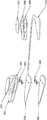
電極アセンブリ
本明細書に記載される電極アセンブリのいずれも、カンチレバー電極装置(または、代替的に、カンチレバー式電極装置、カンチレバー電極アセンブリまたは単に電極アセンブリ)と呼ばれ得、これらのカンチレバー電極装置は、細長いボディに沿って互いから切り離された少なくとも二つの電極領域を含み得る。カンチレバー電極装置は一般に、電極領域と電気的に接触する二つ(またはより多く)の電気コネクタ(本明細書の中ではコネクタと呼ばれ得る)によって神経刺激機器に付く。電気接点は、カンチレバー電極装置が対象によって装着されている間、対象が動き回るときでさえ、神経刺激器への確実な取り付けを可能にし、かつ、電気的接触の断絶を防ぐ特定のやり方で、カンチレバー電極装置上で互いに隣接して配置され得る。たとえば、コネクタの間隔は、中心で(中心間で)0.6〜0.9インチであり、より好ましくは約0.7インチ〜約0.8インチであり得る。電気コネクタは一般に、カンチレバー電極装置の他の点では実質的に平坦な面から延び、神経刺激器の中に嵌まり込み得る。電気コネクタは、神経刺激器と機械的に係合し得(たとえば、両方がスナップであり得)、それがまた、カンチレバー電極装置と神経刺激器との間の接続のための機械的支持を提供し、それにより、カンチレバー電極装置が対象に取り付けられているとき、神経刺激器を対象の体に対して支持し、保持するのに役立ち得る。
Electrode assemblies Any of the electrode assemblies described herein can be referred to as cantilever electrode devices (or alternatively cantilever electrode devices, cantilever electrode assemblies or simply electrode assemblies), and these cantilever electrode devices are It may include at least two electrode regions separated from each other along the elongated body. The cantilever electrode device is typically attached to the nerve stimulation device by two (or more) electrical connectors (which may be referred to herein as connectors) in electrical contact with the electrode region. The electrical contacts allow the cantilever electrode device to be securely attached to the neurostimulator even when the subject moves around while the cantilever electrode device is worn by the subject, and in a specific way to prevent disconnection of the electrical contact. It can be arranged adjacent to each other on the electrode device. For example, the connector spacing may be 0.6-0.9 inches at the center (between the centers), more preferably about 0.7 inches to about 0.8 inches. The electrical connector generally extends from an otherwise substantially flat surface in the cantilever electrode device and can fit into the nerve stimulator. The electrical connector can be mechanically engaged with the neurostimulator (eg, both can be snaps), which also provides mechanical support for the connection between the cantilever electrode device and the neurostimulator Thus, when the cantilever electrode device is attached to the subject, it can help support and hold the neurostimulator against the subject's body.
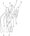
概して、カンチレバー電極装置は、カンチレバー電極装置の細長いボディの一つの端部領域またはその近くに二つ以上のコネクタを含み、二つ(またはより多く)の電極領域がカンチレバー電極装置の細長いボディに沿って配置されている。二つ以上のコネクタ(電気コネクタとも呼ばれ得る)は、一つの端部領域にあり、第二の電極領域がカンチレバー電極装置の細長いボディに沿ってコネクタおよび別の電極領域から離れて(たとえば、2インチ超、3インチ超、4インチ超など)配置されているときでさえ、カンチレバー電極装置全体を神経刺激器に固定するのに役立ち得る。 Generally, a cantilever electrode device includes two or more connectors at or near one end region of an elongated body of the cantilever electrode device, with two (or more) electrode regions along the elongated body of the cantilever electrode device. Are arranged. Two or more connectors (which may also be referred to as electrical connectors) are in one end region and a second electrode region is separated from the connector and another electrode region along the elongated body of the cantilever electrode device (e.g., Even when deployed (greater than 2 inches, greater than 3 inches, greater than 4 inches, etc.), it can help secure the entire cantilever electrode device to the nerve stimulator.
本明細書に記載されるカンチレバー電極装置の各電極領域は一般に、対象と接触するように適合されている電極領域の背面側に活性領域を含む。活性領域は、神経刺激器から対象の皮膚にエネルギー(たとえば電流)を伝達するヒドロゲルを含み得る。活性領域はコネクタと電気的に連絡する。 Each electrode region of the cantilever electrode device described herein generally includes an active region on the back side of the electrode region that is adapted to contact the subject. The active region can include a hydrogel that transfers energy (eg, current) from the neurostimulator to the subject's skin. The active area is in electrical communication with the connector.
概して、カンチレバー電極装置を形成する細長いボディは、別の方向には可撓性であっても、少なくとも一つの方向には硬い材料で作られ得る。たとえば、カンチレバー電極装置の細長いボディは、相対的に薄い(たとえば、3mm未満、2mm未満、1mm未満など)相対的に平坦な材料(たとえばフレックス回路材料)のシートで形成され得る。材料シートは平面に延び得、材料は、その平面の方向には曲げられ得ないが、その方向の外へは曲げられ得(たとえば上下にカーブさせることができ)、ねじれ得る。この部分的な剛性が、カンチレバー電極装置を体に支持するのに役立ちながらも、それが広く多様な対象の体格に適合することを許し得る。いくつかの変形において、カンチレバー電極装置は、硬い材料でできているが、力の適用によって曲げて形を保持させることができる。たとえば、カンチレバー電極装置の細長いボディは延性であり得、たとえば、曲げを可能にする形状記憶材料で作られ得る(少なくとも部分的に)。 In general, the elongate body forming the cantilever electrode device can be made of a stiff material in at least one direction, while being flexible in another direction. For example, the elongate body of the cantilever electrode device can be formed of a sheet of relatively thin material (eg, flex circuit material) that is relatively thin (eg, less than 3 mm, less than 2 mm, less than 1 mm, etc.). The material sheet can extend in a plane, and the material cannot be bent in the direction of the plane, but can be bent out of that direction (eg, can be curved up and down) and twisted. While this partial stiffness helps to support the cantilever electrode device on the body, it can allow it to fit the physique of a wide variety of subjects. In some variations, the cantilever electrode device is made of a hard material, but can be bent and held in shape by the application of force. For example, the elongated body of the cantilever electrode device can be ductile, for example, made (at least partially) of a shape memory material that allows bending.
本明細書に記載されるカンチレバー電極装置の構成は、他の可能な構成に比べ、ワイヤまたは別個の接続が第二の(またはより多くの)電極領域を神経刺激器に接続する変形を含む、数多くの恩典を提供し得る。コネクタおよびケーブル(またはワイヤ)を有する電極セットの製造は、時間消費的であり、費用を要する可能性があり、かつばらつきまたは不十分な収率の原因であり得る。本明細書に記載される電極装置は、より一貫性であり、頑丈であり、大規模で製造可能である。たとえば、本明細書に記載されるカンチレバー電極装置は、各電極の活性区域を包囲する少なくとも数mmの接着剤を含み得、それが、カンチレバー電極装置がウェアラブル神経刺激器に取り付けられているとき、皮膚との良好な接触を形成するのに役立ち得る。側頭に(たとえば眼に隣接して)装着されるように構成されている電極装置およびマイクロ刺激器の場合、ユニットが側頭で眼に向かって、および/または髪の生え際に向かって延びすぎることを防ぐために、電極装置の一部分、特に、電極の下縁よりも下および/または上縁よりも上に位置する部分における接着剤の量は限られ得る。いくつかの変形においては、機器を装着しているとき装着され得る眼鏡のつる部分(たとえば、耳に隣接する部位)に干渉しないよう、上にかぶさるハードウェアユニットが面に配置されているカンチレバー電極装置および電気刺激器を有することが望ましい。加えて、自己配置のための容易な目印である、眼の縁と水平方向に整合させるために機器の下縁を使用する自己配置を案内しやすくするために、カンチレバー電極アセンブリの下縁(第一の電極部分にある)が電気刺激器の下縁と一致することが有利であり得;したがって、電極の下寄り区分の下/周囲の接着剤の量を制限することが有利であり得る。 The configuration of the cantilever electrode device described herein includes a variation in which a wire or a separate connection connects a second (or more) electrode region to the neurostimulator compared to other possible configurations. Numerous benefits can be provided. The manufacture of electrode sets with connectors and cables (or wires) is time consuming, can be costly, and can cause variations or poor yields. The electrode devices described herein are more consistent, rugged and can be manufactured on a large scale. For example, the cantilever electrode device described herein can include at least a few millimeters of adhesive surrounding the active area of each electrode, when the cantilever electrode device is attached to a wearable nerve stimulator, Can help to make good contact with the skin. For electrode devices and micro stimulators that are configured to be worn temporally (eg adjacent to the eye), the unit extends too far towards the eye and / or toward the hairline In order to prevent this, the amount of adhesive in a part of the electrode device, in particular the part located below the lower edge and / or above the upper edge of the electrode, may be limited. In some variations, a cantilever electrode with a hardware unit over it placed on the surface so as not to interfere with the vine portion of the glasses that may be worn when the device is worn (eg, a site adjacent to the ear) It is desirable to have a device and an electrical stimulator. In addition, the lower edge of the cantilever electrode assembly (secondary) is used to facilitate self-positioning, which is an easy landmark for self-positioning, using the lower edge of the instrument to align horizontally with the eye edge. It may be advantageous to match the lower edge of the electrical stimulator; therefore, it may be advantageous to limit the amount of adhesive under / around the lower section of the electrode.
また、上述したように、カンチレバー電極装置の活性領域を電気刺激器に機械的かつ電気的の両方で電気的に接続するためのコネクタを使用する数多くの恩典がある。たとえば、機械的かつ電気的コネクタ、たとえば相対的に薄いカンチレバー電極装置から突き出るスナップコネクタまたは他のコネクタを使用する装置は、装置の誤調節を防ぎ得る。特に、ウェアラブル装置とカンチレバー電極装置とを接続するためにワイヤのみまたは一つのスナップとワイヤとを有するよりも二つのコネクタ(たとえばスナップ)を有することが有利であり得る。第二の機械的/電気的コネクタ、たとえばスナップが、電極、接着パッドおよびハードウェアユニット(神経刺激器/電気刺激器)の間の物理的接続を改善し得る。加えて、眼鏡を装着するユーザの場合、ハードウェアユニット(神経刺激器/電気刺激器)および電極装置は眼鏡フレームのつる部分の下にフィットし得;したがって、複合アセンブリ(電極アセンブリおよび神経刺激器)の部分は、理想的には、眼鏡と側頭部位との間にフィットするのに十分なほど薄くあるべきである。しかし、また、システムのいくらかの部分(たとえば神経刺激器)は、充電と充電との間に妥当な量の時間(たとえば、少なくとも20分の電気刺激、少なくとも30分の電気刺激、少なくとも40分の電気刺激、少なくとも50分の電気刺激、少なくとも60分の電気刺激、少なくとも120分の電気刺激など)にユニットが使用されることができるよう、装置が十分なバッテリ(または他の電源部分)を収容するのに十分なほど厚いことが有利であり得る。したがって、神経刺激器の一つの部分は、一つの端部領域(たとえば、顔の上でより高いところに装着される端部)で標準的なバッテリおよび/または回路を許すのに十分な厚さであり得る。したがって、カンチレバー電極アセンブリから突き出て延びる、スナップのような機械的/電気的コネクタを、神経刺激器のバッテリ区画から切り離された、より薄い端部の近くに配置して、いくつかの変形におけるシステムの全厚さを減らし、コネクタレセプタクルを、厚いバッテリ部分の下(またはバッテリとPCBの両方の下)ではなく、PCBの下(または、PCBのスルーホール/削除部の中)に位置させることが有利であり得る。しかし、いくつかの変形においては、コネクタをバッテリ部分の下に配置する、または一つのコネクタをバッテリ部分の下に配置し、一つのコネクタを、バッテリ部分から切り離されたより薄い領域の下に配置することが有利であり得る。 Also, as described above, there are numerous benefits of using a connector to electrically connect the active area of the cantilever electrode device to the electrical stimulator both mechanically and electrically. For example, devices that use mechanical and electrical connectors, such as snap connectors or other connectors that protrude from a relatively thin cantilever electrode device, can prevent misadjustment of the device. In particular, it may be advantageous to have two connectors (eg snaps) rather than having only a wire or one snap and wire to connect the wearable device and the cantilever electrode device. A second mechanical / electrical connector, such as a snap, may improve the physical connection between the electrode, the adhesive pad and the hardware unit (neural stimulator / electric stimulator). In addition, for users wearing spectacles, the hardware unit (neural stimulator / electrical stimulator) and electrode device may fit under the vine portion of the spectacle frame; thus, the composite assembly (electrode assembly and neurostimulator) ) Should ideally be thin enough to fit between the glasses and the temporal region. However, some parts of the system (eg, neurostimulators) may also have a reasonable amount of time between charges (eg, at least 20 minutes electrical stimulation, at least 30 minutes electrical stimulation, at least 40 minutes). The device contains enough battery (or other power supply part) so that the unit can be used for electrical stimulation, electrical stimulation of at least 50 minutes, electrical stimulation of at least 60 minutes, electrical stimulation of at least 120 minutes, etc. It may be advantageous to be thick enough to do so. Thus, one portion of the neurostimulator is thick enough to allow standard batteries and / or circuitry in one end area (eg, the end worn higher on the face). It can be. Thus, a snap-like mechanical / electrical connector that protrudes out of the cantilever electrode assembly is placed near the thinner end, disconnected from the battery compartment of the neurostimulator, to provide a system in several variations Reduce the total thickness of the connector and position the connector receptacle under the PCB (or in the PCB through-hole / removal) instead of under the thick battery part (or under both the battery and the PCB) Can be advantageous. However, in some variations, the connector is placed under the battery part, or one connector is placed under the battery part, and one connector is placed under a thinner area separated from the battery part. It can be advantageous.
たとえば、いくつかの変形においては、電極アセンブリ(たとえばカンチレバー電極アセンブリ)上の一つのコネクタを、神経刺激器ハードウェアの、額の上で一番高く位置する部分の近くに有することが有利であり得;これは、機器のこの上寄り部分が電極から離れないことを保証するのに役立ち得る。離れるならば、ハードウェアユニットの重量が電極を頭からさらに引き離し、最終的には、電極活性領域と皮膚との間の不十分な(すなわち、不均一な、一貫しない、または高インピーダンスの)接触を生じさせ得る。神経刺激器と電極アセンブリとの間に接着剤を使用してこれを防ぎ得;代替的または追加的に、さらなる機械的コネクタを使用してもよい(接着剤は、ある種の機械的コネクタとみなされ得、電極アセンブリおよび/または神経刺激器ボディ上に存在し得る)。 For example, in some variations it may be advantageous to have one connector on the electrode assembly (eg, cantilever electrode assembly) near the highest portion of the neurostimulator hardware on the forehead. This can help to ensure that this upper part of the device does not leave the electrode. If so, the weight of the hardware unit further pulls the electrode away from the head, and ultimately the poor (ie non-uniform, inconsistent or high impedance) contact between the electrode active area and the skin Can be produced. An adhesive may be used between the neurostimulator and the electrode assembly to prevent this; alternatively or in addition, additional mechanical connectors may be used (the adhesive may be used with certain mechanical connectors) And can be present on the electrode assembly and / or the neurostimulator body).
また、電気的/機械的コネクタ(たとえばスナップ)の少なくとも一つを第一の電極部分の活性領域またはその近く(好ましくは背後)に有することが有利であり得る。理由は、このことがハードウェアユニットとの電気接続をより容易かつより頑丈にし得るからである。電気的/機械的コネクタ(たとえばスナップ)の少なくとも一つを第一の電極部分の活性領域またはその近く(好ましくは背後)に有することが有利であり得るもう一つの理由は、刺激機器上の活性領域およびコネクタレセプタクルの両方が刺激器の電極部分および皮膚と対向する側内の中央に配置され得ることである。第一の活性領域を電極部分内の中央に(すなわち、電極部分の縁から離して)配置することは、いくつかの場合、対象の皮膚との接触の均一さを改善するために活性領域の周囲に接着剤が配置されるとき、好都合である。コネクタレセプタクル(たとえばスナップのための)をウェアラブル電気刺激器中の中央に配置することもまた、好都合である。理由は、レセプタクルは垂直方向の隙間を必要とし、かつ刺激機器の縁の近くでは容易にフィットし得ないからである。 It may also be advantageous to have at least one of electrical / mechanical connectors (eg snaps) at or near (preferably behind) the active area of the first electrode portion. The reason is that this can make the electrical connection with the hardware unit easier and more robust. Another reason that it may be advantageous to have at least one of the electrical / mechanical connectors (eg snaps) at or near (preferably behind) the active area of the first electrode portion is the activity on the stimulating device Both the region and the connector receptacle can be centrally located within the stimulator electrode portion and the side facing the skin. Placing the first active region centrally within the electrode portion (ie, away from the edge of the electrode portion) can in some cases improve the uniformity of contact with the subject's skin. It is advantageous when an adhesive is placed around. It is also advantageous to center the connector receptacle (eg for snapping) in the wearable electrical stimulator. The reason is that the receptacle requires a vertical gap and cannot easily fit near the edge of the stimulator.
図7A〜7Fを参照してさらに詳細に説明するように、神経刺激器の全体形状は三角形であり得、特に、電極装置に接続し、患者と対向するように適合された神経刺激器の面(カーブ/凹状であり、ねじれているが)は三つの辺を有し得る(たとえば略三角形)。この略三角形は、丸みを帯びた縁を含み得、刺激器の厚さ(カンチレバー電極装置と接触する面に対して垂直な方向)は変化し得、たとえば、一つの辺、特に眼の縁から耳の方向に横に延びる辺(眼窩縁と耳介縁との間の部分)に沿う辺がより薄くあり得る。この形状はまた、髪を有しない傾向にある顔/頭の部位で、大部分の人にフィット/装着するのに役立つとき、有利であり得る。活性電極領域を覆い得る接着剤および導電性ヒドロゲルはいずれも、髪をほとんどまたは全く有しない皮膚の上でより効果的に機能する。このより薄い下寄りの角部(眼窩/耳介側角部)はまゆ毛と生え際との間にフィットし得、より幅広い部分は、髪がある可能性が低い額区域に配置される。 As will be described in more detail with reference to FIGS. 7A-7F, the overall shape of the neurostimulator may be triangular, in particular the face of the neurostimulator connected to the electrode device and adapted to face the patient (Although it is curved / concave and twisted) may have three sides (eg, approximately triangular). This generally triangular shape can include rounded edges, and the thickness of the stimulator (in the direction perpendicular to the surface in contact with the cantilever electrode device) can vary, for example from one side, in particular the edge of the eye The side along the side that extends laterally in the direction of the ear (the part between the orbital edge and the pinna edge) can be thinner. This shape can also be advantageous when it helps to fit / wear the majority of people at face / head sites that tend to have no hair. Both adhesives and conductive hydrogels that can cover the active electrode area function more effectively on the skin with little or no hair. This thinner lower corner (orbital / auricular corner) can fit between the eyebrows and the hairline and the wider part is placed in the forehead area where it is unlikely that there will be hair.
図1A〜1Dおよび2は、対象の頭に装着される神経刺激器と共に使用され得るカンチレバー電極装置(「電極装置」)の一つの変形を示す。この例において、カンチレバー電極装置100は複数の電極部分(二つを示す)103、105を含む。図1Aには、正面斜視図が示されている。前面側とは、装着されたとき対象と対向しない側である。カンチレバー電極装置は薄く、そのため電極部分は前面側(図1Aおよび1Bに見える)および背面側(図1Dに見える)を含む。図1Cの側面図に示すように、機器は、電極部分103、105および二つの電極部分の間に延びる細長いボディ領域107を含む薄いボディを有する。細長いボディはまた、薄い(厚さよりもずっと大きな直径および高さを有する)。厚さは図1Cに示されている。
1A-1D and 2 show one variation of a cantilever electrode device (“electrode device”) that may be used with a neural stimulator worn on the subject's head. In this example, the
この例においては、二つのコネクタ115、117(この例ではスナップとして示す電気的かつ機械的コネクタ)がカンチレバー電極装置の前面から延びている。第一の電気部分103の前面はまた、任意のフォームおよび/または接着剤121を含み得、それを通過してスナップが第一の電気部分から突き出て延びている。第一の電気部分は、スナップが電気刺激器上のプラグ(ポート、ホルダ、開口、メス型嵌め合い部品など)に接続するように成形され、サイズ決めされている。上記のように、コネクタは、約0.6〜約0.9インチ(たとえば、図1A〜1Dおよび2に約0.72インチとして示すように、約0.7〜約0.8インチなど)離間し得る。第二の電極部分もまた、フォームまたは裏当て部分123を含み得る。このフォーム/裏当て領域は任意であり得る。いくつかの変形において、コネクタ間の距離は0.7〜0.8に限定されず、より大きくてもよいし(たとえば、0.7〜1.2インチ、0.7〜1.1インチ、0.7〜1.0インチ、0.7〜0.9インチなど)、より小さくてもよい(たとえば、0.2〜0.7、0.3〜0.7、0.4〜0.7、0.5〜0.7、0.6〜0.7インチなど)。
In this example, two
図1Dは、カンチレバー電極装置のこの第一の例の背面図を示す。この例において、第一の電極部分103および第二の電極部分105が示され、活性領域133、135を含む。活性領域は接着剤140によって縁取られている。第一の電極部分103は、背面(患者と接触する)側に、延びる接着剤140によって包囲された第一の活性領域133を含む。活性領域は導電性材料(たとえば導電性ゲル)を含み得る。同様に、第二の電極部分105の背面は、たとえばその全周または少なくとも上が接着剤140によって画定される第二の活性領域135を含む。接着剤は、材料を皮膚に対して剥離可能に保持することができる任意の生体適合性接着剤であり得る。
FIG. 1D shows a rear view of this first example of a cantilever electrode device. In this example, a
図2Aおよび2Bは、図1A〜1Dの例示的なカンチレバー電極装置の分解図を示す。図2A中、カンチレバー電極装置の前面側は、フォーム裏当て121、123(片面または両面が接着性であり得る)材料およびスナップ117および115を取り外した状態で示されている。スナップは、二つの部分(図2Aには示さず)、すなわちベースおよびポストを含み得、ベースは、カンチレバー電極装置のための基材(またはベース)108を形成する細長いボディの背面側に配置され得る。ベースは、たとえば相対的に絶縁性であり、材料の面外に可撓性であるが、平面の中では硬い(すなわち、面外に上下に曲げることはできるが、材料の平面の方向に押され/引かれるときには剛性を示す)フレックス回路材料であり得る。フレックス回路は、前面および/または背面側のすべてまたは一部を覆い、導電性トレースを被覆し、絶縁する誘電体層を有し得る。電極領域およびコネクタを形成するために使用される構造の多くは、ベースに直に印刷されてもよいし、またはベースに付着されてもよい(たとえば、フレキソ印刷、シルクスクリーン印刷または導電性インクを用いるレーザプリントによって)。たとえば、図2Bには、カンチレバー電極装置のベースの背面(患者と対向する)側が、スナップのベースが背面側に沿って延び、かつ、一つの場合には、第一の電極部分の一部を形成する導電性の第一の活性領域と電気的に接触することができるようにスナップが取り付けられた状態で示されている。第二のスナップは、第一の電気活性領域からオフセットされ、第二の活性領域と接触するまで細長いボディ領域107に沿って延びる導電性トレース(たとえば、ベースのボディ108に印刷された)と接触し得る。このようにして、第一および第二のコネクタは、活性領域と神経刺激器との間に電気的連絡を確立し得る。図2B中、活性領域は導電性ゲルを含む(しかし、犠牲材料、pH緩衝材、抗菌/殺菌剤、麻酔剤、かゆみ止めなどを含むさらなる物質)。また、接着部分140がこの分解図に示されている。
2A and 2B show exploded views of the exemplary cantilever electrode device of FIGS. In FIG. 2A, the front side of the cantilever electrode device is shown with the
上記のように、第一および第二の電極部分の前面側のいずれかまたは両方の上のフォーム材料は省略されてもよい。図3は、同じく、または代替的に、カンチレバー電極装置を神経刺激器に固定することに役立つための接着剤であり得るフォーム材料がカンチレバー電極装置に含まれない例を示す。この例においては、コネクタ(スナップ117、115)だけを使用してカンチレバー電極装置を神経刺激器に固定し得る。
As noted above, foam material on either or both of the front sides of the first and second electrode portions may be omitted. FIG. 3 also, or alternatively, illustrates an example where the cantilever electrode device does not include a foam material that can be an adhesive to help secure the cantilever electrode device to the nerve stimulator. In this example, only the connectors (
図1A〜3に示すカンチレバー電極装置は、たとえば、神経刺激器を対象の頭に接続する場合に特に有用であり得る(以下、図6に示すように)。神経刺激器は、プラウドコネクタの上にスナップ嵌めすることにより、カンチレバー電極装置の前面側に取り付けられ、細長いボディ領域107は曲げられて対象の頭の後から下に患者の首の背面の中心線上の部分まで延びる。第一の電極部分および第二の電極部分はいずれも、「TRANSDERMAL ELECTRICAL STIMULATION METHODS FOR MODIFYING OR INDUClNG COGNITIVE STATE」と題する、2014年6月30日に出願され、参照により全体として本明細書に組み入れられる出願第14/320,443号(公開番号US-2015-0005840-A1)に記載されているように、電気活性領域が皮膚に当たる状態で接着的に保持されて、神経刺激器がエネルギー、特に波形を印加することを許し得る。
The cantilever electrode device shown in FIGS. 1A-3 may be particularly useful, for example, when connecting a neurostimulator to the subject's head (as shown in FIG. 6 below). The neurostimulator is attached to the front side of the cantilever electrode device by snap-fitting onto the ploude connector, and the
図1A〜3に示す変形に類似したカンチレバー電極装置のもう一つの例が図13A〜13Dに示されている。この例において、カンチレバー電極装置1300は二つの電極部分1303、1305を含み、二つの電極部分それぞれが少なくとも一つの活性領域1333、1335を有する。図1Aは正面斜視図を示し、図1Bは正面図であり、図1Cは側面図であり、図1Dは背面図である。前面側とは、装着されたとき対象と対向しない側である。電極部分1303、1305は、二つの電極部分の間に延びる細長いボディ領域1307によって接続されている。細長いボディはまた、薄い(厚さよりもずっと大きな直径および高さを有する)。厚さは図13Cによく見える。本明細書における図面はいずれも、別段指示されない限り、一定の縮尺で描かれてはいない。本明細書に記載される変形のいずれかにおける二つの電極領域の間の接続領域の幅は相対的に小さく(ただし、電極装置ボディ領域の厚さよりも広い)、たとえば、約0.5mm〜20mm、約1mm〜15mm、約2mm〜15mm、約3mm〜10mmなどであり得る。
Another example of a cantilever electrode device similar to the variation shown in FIGS. 1A-3 is shown in FIGS. 13A-13D. In this example, the
この例においては、二つのコネクタ1315、1317(電気的コネクタおよび機械的コネクタの両方として働くスナップ)がカンチレバー電極装置の前面から数mm(たとえば1〜5mm)突き出て延びている。この変形は、前面側(たとえば、図1A〜3に示すような、第一および/または第二の電気部分上)の任意のフォームまたは接着剤を示さないが、そのようなものが含まれてもよい。上記のように、コネクタは、約0.6〜約0.9インチ(たとえば、図13A〜13Dに約0.72インチとして示すように、約0.7〜約0.8インチなど)離間し得る。図13Dは、第一の電極部分1303および第二の電極部分1305が同じく示され、活性領域1333、1335を含む背面図を示す。活性領域は接着剤1340によって縁取られている。第一の電極部分1303は、背面(患者と接触する)側に、活性領域の全周を包囲する接着剤1340によって包囲された第一の活性領域1333を含む。活性領域の周囲のすべてまたは大部分を包囲する接着剤領域は、カーブした、および/または毛の覆い(たとえばうぶ毛のある)体の部位で、活性領域と対象の皮膚との間のできるかぎり均一な電気的接触を保証するのに有利である。活性領域は導電性材料(たとえば導電性ヒドロゲル)を含み得る。同様に、第二の電極部分1305の背面は、上下の側が接着剤1340によって画定される第二の活性領域1335を含む。接着剤は、材料を皮膚に対して剥離可能に保持することができる任意の生体適合性接着剤であり得る。これらの例示的カンチレバー電極装置に示されたコネクタはスナップであるが、他のタイプのコネクタは、クランプ、スクリュー、クラスプ、クリップなどを含み得る。
In this example, two
図22A〜22Fは、図1A〜1Dおよび図13A〜13Dに示すものに類似するカンチレバー電極装置(またはカンチレバー電極アセンブリ)のもう一つの変形を示す。この例において、装置の前面は、図1A〜3および13A〜13Dに記載されたものと類似する、または同一である、約0.7〜0.8インチ離間した一対のコネクタ2215、2215'(スナップとして示す)を含む。この例において、第二の電極領域(たとえば装着者の首に配置され得る)は細長い接続部材の方向に水平に向けられている。これは、パッケージングおよび製造のためにアセンブリ全体をよりコンパクトにすることを許し得る。図22Bは、導電性ヒドロゲルを含み得る電気活性領域2205、2209を含む装置の背面図を示す。この例において、電気活性領域2205、2209は、二つの皮膚接触電極領域2227、2229の縁から縁まで延び得る。たとえば、第一の導電層および/または犠牲層(および任意の介在する層)は、活性電極領域が標的化され、正しくサイズ決めされながらも、改善された製造可能性のためにヒドロゲル2205の条片が電極領域を一端からもう一端まで覆うことを許すよう、導電性ヒドロゲル(たとえば2205)の下にある区域の一部を含み得る。この構成は装置の構成を簡素化し得る(図1A〜1Dに示すようにヒドロゲルの「島」をピックアンドプレースすることなく形成され得るため)。これらの導電性領域は、各側が接着剤2207、2207'および2217、2217'によって囲われている。たとえば、製造中、接着剤領域によって包囲されたヒドロゲルの島を配置するためのピックアンドプレースまたはさらなるダイカット工程を要することなく、接着剤およびヒドロゲルの平行なレーンがフレックス回路上に配置され得る。図22Bに示す例示的な電極装置において、製造は、二つの電極領域2227、2229における隣接する接着剤およびヒドロゲルの条片またはレーンに対して平行な適切な幅の三つの接着剤レーンを使用し得る。たとえば、接着剤領域2207に適切な幅を有する第一の接着剤レーン、接着剤領域2207'および2217'の組み合わせ区域に適切な幅を有する第二の接着剤レーンおよび接着剤領域2217に適切な幅を有する第三の接着剤レーン(もう一つの例においては、接着剤領域2207'および2217'のために別々の接着剤レーンが使用されてもよい)。同じく製造中、電極装置のヒドロゲル領域2205および2229を覆うのに適切な幅の二つのヒドロゲルレーン。いくつかの例においては、第一の製造工程が接着剤およびヒドロゲルの条片を使い捨ての一時的な基材の上に配置して、接着剤とヒドロゲルとを組み合わせた平行な条片が、電極領域2227および2229に適切な形状を有するようにダイカットされ得るようにし(接着剤領域2207'および2217'を一つの材料レーンから二つの電極領域のための二つの別々の接着剤領域へと分離することを含む)、次いで、ダイカットされたヒドロゲル・接着剤領域が一時的な使い捨て基材から適切な位置にある電極装置に移される。この設計の有利な特徴は、電極装置(およびその製造における部品)を旋回、回転または配置する必要がなく、効率的なロールtoロールフレームワークでより容易に製造することができることである。図22Cおよび22Dは、図22Aの薄いカンチレバー式電極装置の、それぞれ上面図および下面図を示し、図22Eおよび22Fは右および左側面図を示す。
22A-22F show another variation of a cantilever electrode device (or cantilever electrode assembly) similar to that shown in FIGS. 1A-1D and FIGS. 13A-13D. In this example, the front side of the device is a pair of
図4A〜4Dはカンチレバー電極装置のもう一つの例を示す。この例は、図1A〜2Bに示す変形に非常に類似している。コネクタ(スナップ417、415)は、図1A〜1Dに示すものと同じ位置にあり、第一の電極部分403およびフォーム/裏当て材421(同様に、または代替的に、接着剤であってもよい)の形状も同じくである。同じ形状を有する複数の電極装置を有する利点は、それらを一つの神経刺激機器と互換可能に使用することができることである。しかし、図4A〜4Dに示す例は、異なる全体形状を含み、たとえば患者の頭頸部の異なる部位に接続するために使用され得る。特に、二つの電極部分403、405の間に延びる細長いボディ領域407を形成する基材の部分はわずかに異なるふうに成形されている。この例において、カンチレバー電極装置は、たとえば、対象の側頭を第一の電極部分(神経刺激器が接続され得る)と接続するように構成され得、細長いボディ領域は、対象の頭の周りに曲げられて、第二の電極部分が対象の耳の後の部位(たとえば、乳様突起またはその近く)と電気的に接触し得るようにし得る。第一の電極部分405の第一の活性領域433を側頭部位の皮膚と電気的に接触させ、電気活性領域433を包囲する接着剤440を使用して電気活性領域(および取り付けられた神経刺激器)を対象の皮膚上の定位置に確実に保持することにより、第二の電気活性領域もまた、皮膚に対して接着的441に保持され得、第二の電気活性領域435が乳様突起部位と接触するようになる。
4A-4D show another example of a cantilever electrode device. This example is very similar to the variation shown in FIGS. The connectors (
概して、二つの電極部分を接続する細長いボディ領域は、任意の適切な長さであり得るが、概して、数インチよりも長い(たとえば、約2インチよりも長い、約3インチよりも長い、約4インチよりも長い、約5インチよりも長い、約6インチよりも長い、約7インチよりも長い、約8インチよりも長い、約9インチよりも長い、など)。細長いボディ領域はまた、図1A〜3および図4A〜5の変形に示すように、曲がっていてもよいし、カーブしていてもよい。細長いボディがそれ自体に折りたたまれることさえある曲りまたはカーブは、たとえば図6および8Aに示すように材料が対象の頭の上および/または周囲に調節可能に配置されることを許すために材料が撓む、または曲がることを可能にし得る。 In general, the elongated body region connecting the two electrode portions can be any suitable length, but is generally longer than a few inches (eg, longer than about 2 inches, longer than about 3 inches, about Longer than 4 inches, longer than about 5 inches, longer than about 6 inches, longer than about 7 inches, longer than about 8 inches, longer than about 9 inches, etc.). The elongated body region may also be bent or curved as shown in the variations of FIGS. 1A-3 and 4A-5. A bend or curve in which the elongate body may even fold into itself may cause the material to be adjustably placed on and / or around the subject's head, for example as shown in FIGS. 6 and 8A. It may be possible to flex or bend.
図5Aは、図4A〜4Dのカンチレバー電極装置の分解図を示す。この例において、基材(細長いボディ408)は、第一の電極部分403(導電性材料を有する第一の電気活性領域(図5Aには見えない)、電気活性領域を覆うヒドロゲル443、接着剤440および任意の裏当て材421ならびに基材408の一部分で形成)と第二の電極部分405(第二の電気活性領域(見えない)、電気活性領域を覆うヒドロゲル445、接着剤441および任意の裏当て材423ならびに基材408の一部で形成されている)との間に細長いボディ領域を形成する。第二の導電性領域を第二のコネクタ417に接続する一つまたは複数の電気トレースが含まれてもよく、たとえば、基材408上に直に印刷(またはシルクスクリーン印刷など)されてもよい。
FIG. 5A shows an exploded view of the cantilever electrode device of FIGS. In this example, the substrate (elongated body 408) comprises a first electrode portion 403 (a first electroactive region having a conductive material (not visible in FIG. 5A), a
上述したように、コネクタ(ピン415、417)は所定の距離(たとえば約0.7〜0.8インチ)離間し、第一のピン415が背後にあり、第一の電極部分403の第一の導電性領域433と直に電気接触している。第二のコネクタ(ピン417)は第一のコネクタおよび第一の導電性材料から電気的に絶縁され、第一の電気活性領域433の直後にはないが、それでも第一の電極部分403中にあり、第一の電極部分の背面(たとえば、第一の電極部分を形成する基材の背面)から突き出て延びるように配置され得る。
As described above, the connectors (
図14A〜14Dは、図4A〜5に示す変形に類似したカンチレバー電極装置のもう一つの例を示す。図14A〜14D中、カンチレバー電極装置は、図1A〜1Dおよび4A〜4Dに示すほぼ同じ位置に機械的/電気的コネクタ(スナップ1417、1415)を含む。電極装置は第一の電極部分1403および第二の電極部分1405を含む。図14Aおよび14Bはそれぞれ正面斜視図および正面図を示す。この例において、前面側は、いずれの電極部分の周囲にも任意のフォーム/裏当て材またはさらなる接着剤を含まないが、そのようなものが含まれてもよい。図4A〜4Dと同様に、電極装置の全体形状は、対象の側頭を第一の電極部分1403(神経刺激器が接続され得る)に接続するように適合され得、細長いボディ領域は、対象の頭の周りに曲げられ得、第二の電極部分1405は対象の耳の後の部位(たとえば、乳様突起またはその近く)と電気的に接触し得る。第一の電極部分1405の第一の活性領域1433を側頭部位の皮膚と電気的に接触するように配置し、かつ電気活性領域1433を包囲する接着剤1440を使用して電気活性領域(および取り付けられた神経刺激器)を定位置に保持することにより、第二の電気活性領域もまた、皮膚に対して接着的1441に保持され得、第二の電気活性領域1435が乳様突起部位と接触するようになる。
14A-14D show another example of a cantilever electrode device similar to the variation shown in FIGS. 4A-5. 14A-14D, the cantilever electrode device includes mechanical / electrical connectors (
図23A〜23Fもまた、図4A〜5および14A〜14Dで上述したものに類似するカンチレバー式電極アレイのもう一つの例を示す。図23A中、電極アセンブリは、上記のものとほぼ同じ位置にあり、ウェアラブル電気刺激機器(たとえば神経刺激器)と嵌合し、それに固着するように構成されている一対のコネクタ(スナップとして示す)2315、2315'を含む。上記のように、カンチレバー電極装置/アセンブリは一対の皮膚接触電極領域2327、2329を含む。第一の電極領域2327は前面側(装置が装着されたとき、対象と接触しない側)にスナップを含み、スナップは、ウェアラブル電気刺激器に接続し、刺激器を頭に保持し、かつ第一および第二の皮膚接触電極領域2327、2329上の各活性領域への電気的接触を形成する。第二の皮膚接触電極領域2329は、第一の皮膚接触電極領域2327および電気刺激器(取り付けられているとき)からカンチレバー式に離れるが、同じく、たとえば耳の後で対象の皮膚に対して保持される。
FIGS. 23A-23F also show another example of a cantilevered electrode array similar to that described above in FIGS. 4A-5 and 14A-14D. In FIG. 23A, the electrode assembly is in approximately the same position as described above and is a pair of connectors (shown as snaps) that are configured to mate with and affix to a wearable electrical stimulation device (eg, neurostimulator). Including 2315, 2315 ′. As described above, the cantilever electrode device / assembly includes a pair of skin
図23Bは、装置を装着する対象と対向する(そして接触する)ように構成されているカンチレバー式電極装置の背面を示す。この例において、両方の皮膚接触電極領域は、装置の少なくとも一つの縁から皮膚接触電極領域を横切って延びて皮膚接触電極領域上に活性ゾーンを形成する活性領域を含む。たとえば、図23B中、第一の皮膚接触電極領域2327は、皮膚接触電極領域2327を横切って中央条片を形成する活性領域2205を有する。他の例においては、ヒドロゲル2205、2209が電極領域の一つの縁から電極領域のもう一つの縁まで延び得、下にある電極活性区域は、電極が、認知効果を誘発するために効果的に配置されるために適切にサイズ決めされ、配置されることを保証するために、この領域のサブセットを覆うだけである。以下、図20A〜20Fを参照してさらに詳細に説明するように、この活性領域は、コネクタの一つ(たとえばスナップ2315)と電気的に連絡し、電流を活性領域全体に分散するために導電性金属、導電性犠牲層およびヒドロゲルの層構造を含み得;いくつかの変形においては、一つまたは複数のさらなる層、たとえば(導電性金属および犠牲層よりも)導電性が低い、たとえば炭素で構成された層が導電性金属と犠牲層との間に含まれてもよい。このさらなる層は、電流が犠牲層の中に通過する前に電流を活性領域の表面全体に分散させるのに役立ち、したがって、より高い電流強度が電極・皮膚接触区域全体に均一に送達されることを許し、ひいてはユーザにおける不快感を減らし得る。第二の皮膚接触電極領域2229は同様に構成されているが、二つの皮膚接触電極領域の間に延びる可撓性基材2307の部分の上または中にある導電性トレースにより、他のコネクタ(たとえばスナップ2315')に電気的に接続されている。
FIG. 23B shows the back of a cantilever electrode device that is configured to face (and contact) a subject to which the device is to be mounted. In this example, both skin contact electrode regions include an active region that extends across the skin contact electrode region from at least one edge of the device to form an active zone on the skin contact electrode region. For example, in FIG. 23B, the first skin
たとえば、図23A〜23Fに示すカンチレバー式電極装置は、Kapton(たとえばポリイミドフィルム)および/またはビニル(たとえばコートされたビニル、ポリ塩化ビニルまたは関連するポリマー)のような基材で形成され得、その上に様々な領域が積層または付着によって形成される。活性領域は、ヒドロゲル(たとえば、約350 Ohm-cmの抵抗を有するAG602ヒドロゲル)およびAgコーティング(たとえばAgインク)、Ag/AgClコーティング(たとえばAg/AgClインク)および(任意で)炭素導体(たとえば、約<90 Ohms/cm2の抵抗を有するExopack Z-flo炭素充填ビニル)を含み得る。コネクタは、オス型スナップスタッド(たとえば、<1 Ohm/cm2の抵抗を有するRome Fastener 76 Male Snap Stud)およびアイレット(たとえば、select Engineering Carbon Filled ABSアイレット)を含むファスナであり得る。 For example, the cantilever electrode device shown in FIGS. 23A-23F can be formed of a substrate such as Kapton (eg, polyimide film) and / or vinyl (eg, coated vinyl, polyvinyl chloride or related polymers), Various regions are formed by lamination or deposition on top. The active regions are hydrogels (eg, AG602 hydrogel having a resistance of about 350 Ohm-cm) and Ag coating (eg, Ag ink), Ag / AgCl coating (eg, Ag / AgCl ink) and (optionally) carbon conductor (eg, Exopack Z-flo carbon-filled vinyl having a resistance of about <90 Ohms / cm 2 ). The connector may be a fastener including a male snap stud (eg, Rome Fastener 76 Male Snap Stud having a resistance of <1 Ohm / cm 2 ) and an eyelet (eg, select Engineering Carbon Filled ABS eyelet).
もう一つの変形において、図23A〜23F(または図22A〜22F)に示すようなカンチレバー式電極装置は、基材(たとえばKaptonまたは他のポリマー材料)を含み得、ヒドロゲル(たとえばAG602ヒドロゲル、350 Ohm-cm)、銀/塩化銀犠牲層(たとえばECM Ag/AgClインク(85/15)、<0.2 Ohm/cm2)、任意の炭素層(たとえばDuPont Carbon 5000インク、<50 Ohm/cm2)および銀層(たとえばEMC銀インク、<0.2 Ohm/cm2)を有する活性領域を含み得る。コネクタは、アイレット(たとえばRome 76 SFアイレット、ビニルカバー付き)およびスタッド(たとえばRome 76 Male Snap Stud、1 Ohm/cm2)を含み得る。 In another variation, a cantilevered electrode device as shown in FIGS. 23A-23F (or FIGS. 22A-22F) can include a substrate (eg, Kapton or other polymer material) and a hydrogel (eg, AG602 hydrogel, 350 Ohm) -cm), silver / silver chloride sacrificial layer (eg ECM Ag / AgCl ink (85/15), <0.2 Ohm / cm 2 ), optional carbon layer (eg DuPont Carbon 5000 ink, <50 Ohm / cm 2 ) and An active region having a silver layer (eg, EMC silver ink, <0.2 Ohm / cm 2 ) may be included. The connector may include an eyelet (eg, Rome 76 SF eyelet, with vinyl cover) and a stud (eg, Rome 76 Male Snap Stud, 1 Ohm / cm 2 ).
上記例のいずれにおいても、機械的および/または電気的コネクタが第一の電極部分にまたはその片側近くに(第一の電極部分に対して偏心的に)配置され得る。したがって、その背面で電極装置上の機械的コネクタに接続する神経刺激器は一つの側で接続され得、それが、電極部分の一つの側または領域では一つまたは複数の(たとえば二つの)点で留められる、または保持されるが、神経刺激器のもう一方の端または領域が、電極装置の第一の電極部分の残りに対して浮くことを可能にし得る(すなわち、神経刺激器は、電極装置の第一の電極部分ほど綿密には体のカーブに適合しない)。これは、可撓性電極装置が多様な頭部形状に確実に付くことを許しながらも、装着者が頭を動かす(表情を変える、目を閉じる、目を細めるなどを含む)ときでさえ、第一の電極部分の全部または一部を装着者の頭から移動させる(ユーザの皮膚における電流密度の均一さを低下させ、より多くの不快感を生じさせるであろう)危険を減らしながら、より硬い神経刺激器が付くことを許し得る。 In any of the above examples, a mechanical and / or electrical connector can be placed at or near one side of the first electrode portion (eccentric with respect to the first electrode portion). Thus, the nerve stimulator that connects to the mechanical connector on the electrode device on its back side can be connected on one side, which is one or more (eg two) points on one side or region of the electrode part. Or the other end or region of the neurostimulator may be allowed to float relative to the rest of the first electrode portion of the electrode device (ie, the neurostimulator It does not fit the curve of the body as closely as the first electrode part of the device). This allows the flexible electrode device to reliably attach to a variety of head shapes, but even when the wearer moves his head (including changing facial expressions, closing eyes, narrowing eyes, etc.) While reducing the risk of moving all or part of the first electrode part away from the wearer's head (which would reduce the uniformity of the current density in the user's skin and cause more discomfort), It may allow a hard nerve stimulator to be attached.
上述したように、二つの電極部分を接続する電極装置の細長いボディ領域は、任意の適切な長さであり得るが、概して、数インチよりも長い(たとえば、約2インチよりも長い、約3インチよりも長い、約4インチよりも長い、約5インチよりも長い、約6インチよりも長い、約7インチよりも長い、約8インチよりも長い、約9インチよりも長い、など、2〜12インチ、2〜10インチ、3〜9インチなど)。電極装置の平面において、細長いボディ領域は、図1A〜3、図4A〜5、図13A〜13Dおよび図14A〜14Dの変形に示すような、曲がった、またはカーブした経路で延びて、図6および8Aに示すように、材料が、対象の頭の上および/または周囲に調節可能に配置されることを許すために、撓む、または曲がることを許すのに役立ち得る。 As discussed above, the elongated body region of the electrode device connecting the two electrode portions can be any suitable length, but is generally longer than a few inches (eg, longer than about 2 inches, about 3 Longer than inch, longer than about 4 inches, longer than about 5 inches, longer than about 6 inches, longer than about 7 inches, longer than about 8 inches, longer than about 9 inches, etc. 2 ~ 12 inches, 2-10 inches, 3-9 inches, etc.). In the plane of the electrode device, the elongated body region extends in a curved or curved path, as shown in the variations of FIGS. 1A-3, 4A-5, 13A-13D and 14A-14D. And 8A can help to allow the material to flex or bend to allow it to be adjustably placed on and / or around the subject's head.
次に図5Bを参照すると、図5Bは、図4Aに示す変形と同様に構成されたカンチレバー電極アセンブリのもう一つの例を分解図で示す。カンチレバー電極装置は、第一の電極(活性領域)がユーザの右側頭またはその近くに配置され得、第二の電極(活性領域)がユーザの右側乳様突起上に配置され得るように構成されている。この例において、装置は、カンチレバー電極アセンブリと電気刺激機器(たとえば神経刺激器)との間に位置するように構成された任意の裏当て材421を含む。二つのスルーホールが、一対の導電性スナップ電極505、506が裏当て層421(すなわちフォーム)の中に嵌まることを許して、スナップが刺激機器の導電性レセプタクルに嵌まり込むことができるようにする。図5Bには二つのスナップ506(導電性スナップの対)が示され、そのそれぞれが、刺激ユニットの電流源を皮膚電極に接続する。しかし、いくつかの変形においては、二つよりも多いスナップまたは一つのスナップ(たとえば、二つ以上の電気経路を有する)が使用されてもよい。導電性スナップ506は、アイレット505により、可撓性電極アセンブリ上の定位置に保持され得る。この例におけるスナップおよびアイレットは、第一の電極領域502(第一の電極活性領域を含む)を形成する領域内の基材中のスルーホールを介してリベット留めされる。この例においては、第二の電極活性領域(第二の電極領域)510が、第二の電極活性区域が配置される可撓性電極アセンブリの末端領域に位置している。
Referring now to FIG. 5B, FIG. 5B shows an exploded view of another example of a cantilever electrode assembly configured similar to the variation shown in FIG. 4A. The cantilever electrode device is configured such that the first electrode (active area) can be placed at or near the right side of the user and the second electrode (active area) can be placed on the right mastoid of the user. ing. In this example, the device includes an
図5Cは、カンチレバー電極装置のもう一つの例を分解図で示す。図5Dおよび5Eは、可撓性カンチレバー電極アセンブリのこの変形の、それぞれ正面図および背面図を示す。 FIG. 5C shows another example of a cantilever electrode device in an exploded view. 5D and 5E show a front view and a back view, respectively, of this variation of the flexible cantilever electrode assembly.
図5B中、装置は、第一の活性電極領域を覆うように配置される楕円形のヒドロゲル部分565を含み;活性電極領域は、導電層(すなわちトレースおよび区域)および任意の絶縁材料層を含む基材の上に形成され得る(たとえば、印刷、たとえばシルクスクリーン印刷、フォトリソグラフィー、フレキソ印刷によって、または他のやり方でそれを可撓性基材上に付着させることによって)。第二のヒドロゲル領域507が第二の活性電極領域(たとえば、一つまたは複数の導電層および、いくつかの変形においては、絶縁層を含み得る)の上に配置され得る。皮膚接着領域501が第一の活性電極区域を包囲し得、可撓性アレイが対象の皮膚に付着するのに役立ち得、電極活性区域の周囲への付着を提供して、ヒドロゲルが対象の皮膚との均一かつ堅い接触を形成し得るようにする。また、ヒドロゲルが接着性であってもよい。
In FIG. 5B, the device includes an
いくつかの変形においては、皮膚接着剤501と同一または類似の形状を有し、接着領域の面が可撓性基材502の面からヒドロゲル領域565とほぼ同じ距離になるようにさらなる深さ(厚さ)を加えるスペーサ504が含まれてもよい。図示する変形において、ヒドロゲルは周囲の接着領域からわずかに突き出るが、他の変形において、ヒドロゲルは周囲の接着剤と同一平面であってもよい。ヒドロゲル領域が突き出る変形において、ヒドロゲルは、電極アセンブリが皮膚に接着されるときわずかに圧縮して、ヒドロゲルと皮膚との間の接触の均一さおよび堅固さを改善し得る。同様に、カンチレバー電極のもう一方の端部領域における第二の電極活性領域においては、第二のスペーサ509および皮膚接着剤508が、第二のヒドロゲル507を含む第二の電極区域を同様に包囲し得る。
In some variations, it has the same or similar shape as the
図5Cは、図4Aに示す変形と同様に構成された、経皮電気刺激のための可撓性電極アセンブリ部品の分解図を示す。装置は、第一の電極活性領域が対象の右側頭またはその近くに配置され、第二の電極活性領域が対象の右乳様突起部位に配置され得るような形状に構成されている。 FIG. 5C shows an exploded view of a flexible electrode assembly component for transcutaneous electrical stimulation configured similarly to the variation shown in FIG. 4A. The device is configured such that the first electrode active region can be located at or near the right temporal region of the subject and the second electrode active region can be located at the right mastoid portion of the subject.
いくつかの変形において、装置は複数の基材層で形成され得る。たとえば、図5C中、電極装置は、絶縁層である皮膚対向誘電体510層を含む。さらなる誘電体層515が、外を向くように配置されてもよく(皮膚および皮膚対向層から遠い)、二つのスナップコネクタが層を通過することができるような切り抜き領域(削除部)を有してもよい。層はまた、内部可撓性電極基材511にはんだ付けされるコンデンサが十分な隙間を有するよう、一つまたは複数の小さな長方形削除部を含んでもよい。上515(外向き)および下510(皮膚と対向する)層は、コーティングであってもよいし、または内部基材511に接着的に取り付けられる固体材料で形成されてもよい。
In some variations, the device may be formed with multiple substrate layers. For example, in FIG. 5C, the electrode device includes a skin-facing
この例において、楕円形領域555は、可撓性基材511上に形成または付着され、導体および/または犠牲層(たとえば、以下さらに詳細に説明するAg/AgCl層)で形成されて、第一の電極活性領域を形成し得る印刷(シルクスクリーン印刷など)された領域である。この例において、Ag/AgCl領域は、スナップ電極のアイレット部分が活性電極区域と直に接触しないような丸い削除区域を有する。スナップと電極との間の直接接触は、含まれる部品の化学作用により、電極区域の酸化を生じさせたり、またはガルバニ電池を創製したりするおそれがある。
In this example, the
代替態様(図示しない。理想的には、他の非反応性部品を有する)において、上を覆う導電性スナップのアイレットは、アイレットの頂部が電極区域と導電性になるよう、活性電極を通してリベット留めされることができる。 In an alternative embodiment (not shown; ideally with other non-reactive components), the overlying conductive snap eyelet is riveted through the active electrode so that the top of the eyelet is conductive with the electrode area. Can be done.
図5C〜5Eはまた、電気活性領域を電気的/機械的コネクタ、たとえば第二の電極活性領域に接続するための、本明細書に記載される変形のいずれかの上に存在し得る様々な導電性トレースを示す。たとえば、導電性トレース553は、可撓性電極装置の皮膚対向側に形成され得、装置の第二の(外向き)側から電極区域に通過する導電路を介して電流を誘導し得る。また、導電性の非消耗性(すなわち金属)層(たとえばAg、Cu、Au、導電性炭素など)が、第一および/または第二の電気活性領域を形成する一つの層として含まれてもよい(図5Cには示さず)。この導電性の非消耗性層は、トレース553からつながった領域として印刷され得、Ag/AgCl層555(「犠牲層」)と同様な形状を有し、このAg/AgCl層は、可撓性基材上に印刷された導電層と上を覆うヒドロゲルとの間に短絡が起こらないことを保証するために、そのすべての境界(存在するならば、円形削除部の内部境界を含む)で、下にある導電性領域よりもわずかに上に延びる。そのような短絡は、電流をしてpH緩衝Ag/AgCl層をバイパスさせ、経皮電気刺激の快適さおよび効能を低下させるおそれがある。
FIGS. 5C-5E also illustrate various types that may exist on any of the variations described herein for connecting an electroactive region to an electrical / mechanical connector, eg, a second electrode active region. A conductive trace is shown. For example,
同様に、第二の電気活性領域(図5Cに示すように、乳様突起の上に配置されるように構成され得る)の場合にも、導電性トレース519が、第一の電極活性領域の導電性トレース553と機能的に類似し得、Ag/AgCl層561またはAg/AgCl層と接触する(かつ、それによって全周辺を包囲される)導電性非消耗性層と一致するように配置され、成形され得る。
Similarly, in the case of a second electroactive region (which can be configured to be placed over a mastoid, as shown in FIG. 5C),
この例において、可撓性基材511(たとえば、ポリエチレンのような材料で形成されている)がベースを形成し得、そのベースの上に、電極および任意の回路素子が印刷および/または付着、糊付け、接着、シルクスクリーン印刷などされる。基材511は、二つ以上の導電性スナップコネクタのためのスルーホールを含み得;スナップコネクタは図5Cには示されないが、先に図5Bで説明されたものに類似し得る。
In this example, a flexible substrate 511 (eg, formed of a material such as polyethylene) can form a base on which electrodes and optional circuit elements are printed and / or deposited, Gluing, bonding, silk screen printing, etc. The
この例においては、二つ以上の導電性炭素円形領域514および517がスナップと導電性トレースとの間に結合され得る。この例におけるトレース512および513は、電極アセンブリ識別のための容量素子の一部として使用され得るコンデンサによって接続される(以下さらに詳細に説明する)。コンデンサは図5Cには示されないが、たとえば、第一および第二の活性領域、たとえば二つの電気コネクタ(たとえばスナップ)の間をトレース512、513によって接続するであろう。トレース518が、第一の電極領域(たとえば、含まれるならば、導電性非消耗性層)とつながっている電極アセンブリの皮膚対向側のトレース553への導電路(図示せず)に電流を運び得る。
In this example, two or more conductive carbon
同様に、トレース516が、電流を、導電路519に通して、第二の電極活性領域(たとえば、含まれるならば、導電性非消耗性層)とつながっている可撓性電極アセンブリの皮膚対向側のトレース519に運び得る。
Similarly, the skin facing of the flexible electrode assembly in which trace 516 passes current through
図5Dおよび5Eは、図5Cに示すもののような可撓性電極アセンブリの、それぞれ正面図(皮膚と対向しない)および背面図(皮膚と対向する)を示す。電極装置の平面において、第一の電極活性領域は基端520にあり、第二の電極装置は末端領域530にある。
5D and 5E show a front view (not facing the skin) and a rear view (facing the skin), respectively, of a flexible electrode assembly such as that shown in FIG. 5C. In the plane of the electrode device, the first electrode active region is at the
本明細書に記載される変形のいずれにおいても、導電層、たとえば導電性炭素または別の導電性材料(たとえば環523)が、電気刺激ユニット中のレセプタクルに嵌まる導電性スナップ(図示せず)および電流を第一の電極534に送るトレースに接続し得る。導電性炭素環521の一つが、電気刺激ユニット中のレセプタクルに嵌まる導電性スナップおよび電流を第二の電極活性領域536に送る一つまたは複数のトレースに接続し得る。
In any of the variations described herein, a conductive snap (not shown) in which a conductive layer, eg, conductive carbon or another conductive material (eg, ring 523) fits into a receptacle in the electrical stimulation unit. And a trace that sends current to the
この例において、装置の前面(対象の皮膚と対向しない)側の導電性トレース524が、電流を導電性コネクタ(たとえば導電性炭素層)から導電路(図示せず)に通して皮膚対向(背面)側のトレース533に送り、次いで、導電層(たとえば、非消耗性導電層および重ねられた消耗性導電層ならびにヒドロゲル層)で形成され得る第一の電極活性領域534に送る。この例における導電層の少なくとも一部分は、電気的(かつ機械的)コネクタ、この例においてはスナップ(図示せず)が通過し得る削除区域(活性電極領域の)532およびスルーホール535を含む。基材中の第二のスルーホール531が、第二の電気コネクタ(たとえば導電性スナップ)が可撓性基材に通してリベット留めされるための隙間を提供し得る。図5D中、トレース522および526は、以下で詳細に説明するように電極アセンブリのタイプおよび正確さを識別するために使用され得る容量素子(たとえば、図示しないコンデンサ)を介して二つの電極経路を短絡させるように働き得る。
In this example, a
図6は、対象の頭に装着されたカンチレバー電極装置600の変形を示す。図示するように、装置は、第一の電極部分が側頭領域に接着的に取り付けられ、第二の電極部分が頭の後の部位(たとえば、図示しない、耳の後または首部位)に取り付けられる状態で配置される。 FIG. 6 shows a variation of the cantilever electrode device 600 mounted on the subject's head. As shown, the device has a first electrode portion adhesively attached to the temporal region and a second electrode portion attached to a location behind the head (eg, behind the ear or neck, not shown). Arranged in a state where
神経刺激器(図6には示さず)が、カンチレバー電極装置が対象に適用される前または適用された後のいずれかでカンチレバー電極装置に取り付けられ得る。図7A〜7Fは神経刺激器の一つの変形の斜視図を示し、図8Aは、カンチレバー電極装置と共に対象の頭に適用された装置を示す。図8Bは図7A〜8Aの神経刺激器(電気アプリケータ)の背面図を示す。 A neurostimulator (not shown in FIG. 6) can be attached to the cantilever electrode device either before or after the cantilever electrode device is applied to the subject. 7A-7F show perspective views of one variation of a neurostimulator, and FIG. 8A shows the device applied to a subject's head with a cantilever electrode device. FIG. 8B shows a rear view of the nerve stimulator (electric applicator) of FIGS.
図7A〜7F中、図8Aに示すものと同様に装置が対象によって装着されるところに基づいて様々な辺が標識されている。概して、耳に近いところに装着されるユニットの辺は耳介縁であり、額の一番高いところに装着される辺は上縁であり、眼/まゆ毛にもっとも近いところに装着される辺は眼窩縁である。神経刺激器の全体形状は三角形(丸みのある縁を含む)である。本明細書の中で使用される三角形は、図示するように、三辺の間で丸みのある/滑らかな移行部を有する形状を含む。対象と対向する面は、既定の向きでフィットするように特異的に付形されており、対象が適用のしかたを誤り、取り付けられるカンチレバー電極装置の活性領域を誤った場所に配置することを困難または不可能にしている。カンチレバー電極装置を神経刺激器に取り付けるとき、カンチレバー電極装置は撓み得、または曲がり得、カーブした、またはねじれた面に適合するように付形されている。この面は、面が凹状にカーブする中心の湾曲軸と、そのカーブ面をゆがめ得るねじれ軸とを有する(二つの軸は異なってもよいし、同じであってもよい)サドル形状の区分である。 7A-7F, various sides are labeled based on where the device is worn by the subject, similar to that shown in FIG. 8A. In general, the side of the unit that is attached close to the ear is the auricle edge, the side that is attached to the highest part of the forehead is the upper edge, and the side that is attached closest to the eye / eyebrows is Orbital border. The overall shape of the neurostimulator is a triangle (including rounded edges). The triangles used herein include shapes having a rounded / smooth transition between three sides, as shown. The surface facing the object is specifically shaped to fit in a pre-determined orientation, the object is incorrectly applied and it is difficult to place the active area of the attached cantilever electrode device in the wrong place Or make it impossible. When the cantilever electrode device is attached to the neurostimulator, the cantilever electrode device can be bent or bent and shaped to fit a curved or twisted surface. This surface has a central curved axis whose surface curves concavely and a torsional axis that can distort the curved surface (the two axes may be different or the same), and a saddle-shaped section. is there.
図8Bに示すように、カンチレバー電極装置が付く神経刺激器の下面は、カンチレバー電極装置上のコネクタを受け、それと共に電気的かつ機械的接触を形成するための嵌め合い接合部(開口、レセプタクル、メス型レシーバなど)を含む。これらのレシーバはまた、カンチレバー電極装置の配置を最適化して、神経刺激器および対象との十分な接触を形成し、対象が動く、および/または活動するときでさえ、カンチレバー電極装置が曲がる、または接触を断つことを防ぐことを可能にするように配置され得る。 As shown in FIG. 8B, the underside of the neurostimulator to which the cantilever electrode device is attached receives a connector on the cantilever electrode device and mates with it to form an electrical and mechanical contact (opening, receptacle, Including female receivers). These receivers also optimize the placement of the cantilever electrode device to form sufficient contact with the neurostimulator and the subject so that the cantilever electrode device bends, or even when the subject moves and / or is active It can be arranged to make it possible to prevent breaking contact.
カンチレバー電極装置に関する上記変形は、基材(たとえばフレックス回路)材料が薄く、少なくとも一つの軸において曲がることを許される可撓性構造を示すが、いくつかの変形において、カンチレバー電極装置は硬くてもよい。図9A〜9Cおよび10A〜10Cは、硬質または半硬質のカンチレバー電極装置の二つの変形を示す。 While the above variations on cantilever electrode devices show a flexible structure where the substrate (eg, flex circuit) material is thin and allowed to bend in at least one axis, in some variations the cantilever electrode device may be stiff Good. 9A-9C and 10A-10C show two variants of a rigid or semi-rigid cantilever electrode device.
図9A〜9C中、装置は、頭頸部の様々な部位との接触を可能にするウェアラブルなフォームファクタを達成するために曲げられ得る(延性)、または蝶着され得るカンチレバー電極装置に取り付けられた例示的な神経刺激器903のCAD描画として示されている。神経刺激器(図示せず)は、電子部品のすべてまたはサブセットを含み得、突出するピン905に取り付けられ得る。たとえば、耳の後の右乳様突起を標的化するカソード電極が正しく配置されるようにカンチレバー電極装置の後方部分(たとえば第二の電極領域)が配置され得るとき、アノード電極(第一の電極部分の電気活性領域)が右側頭区域に配置され、導電性であり得る(電極活性領域は図示せず)。 9A-9C, the device is attached to a cantilever electrode device that can be bent (ductile) or hinged to achieve a wearable form factor that allows contact with various parts of the head and neck. A CAD drawing of an exemplary neural stimulator 903 is shown. A neural stimulator (not shown) can include all or a subset of the electronic components and can be attached to the protruding pins 905. For example, when the posterior portion of the cantilever electrode device (eg, the second electrode region) can be positioned so that the cathode electrode targeting the right mastoid process behind the ear is correctly positioned, the anode electrode (first electrode A portion of the electroactive region) is located in the right temporal region and may be conductive (the electrode active region is not shown).
同様に、図10A〜10Cに示す例は、硬く細長いボディを有する領域(細長いボディのコネクタ領域を含む)を示し、細長いボディはさらに延び、対象の首の後で第二の活性領域との接触を許し得る。ボディの全部または一部は、首に適合することを許す形状へと曲げることができるよう、延性であり得る。いくつかの変形において、細長いボディは、使用中に曲がる/撓むことを許すために蝶着されてもよい。 Similarly, the example shown in FIGS. 10A-10C shows a region having a hard, elongated body (including the connector region of the elongated body), which further extends and contacts the second active region after the subject's neck Can forgive. All or part of the body can be ductile so that it can be bent into a shape that allows it to fit into the neck. In some variations, the elongate body may be hinged to allow it to bend / deflate during use.
図11Aおよび11Bは、同じくフレックス回路材料で形成され得る可撓性(少なくとも一つの自由軸で)カンチレバー電極装置のもう一つの変形を示す。図11Aは正面図を示し、図11Bは、他の要素(たとえば活性領域、コネクタ、接着剤など)が取り付けられ得る基材部分の背面図を示す。この例において、機器は、先に図1A〜3および4A〜5に示した変形と同様に、基材ボディの細長く薄いコネクタ部分を含む。例を示すためだけに例示的な寸法(インチ単位の長さ)が示され、変更され得る。 FIGS. 11A and 11B illustrate another variation of a flexible (with at least one free axis) cantilever electrode device that can also be formed of flex circuit material. FIG. 11A shows a front view and FIG. 11B shows a rear view of a substrate portion to which other elements (eg, active areas, connectors, adhesives, etc.) can be attached. In this example, the device includes an elongated thin connector portion of the substrate body, similar to the variations previously shown in FIGS. 1A-3 and 4A-5. Illustrative dimensions (length in inches) are shown and can be varied for example only.
図12は、コネクタが、逆さまの配置で基材の異なる部分に結合され、導電性トレース(図示せず)によって接続され、折り返されて、上記図1A〜3および4A〜5に示すものと同様に、コネクタを可撓性基材に通して活性領域の中へとリベット留めすることなく、第一の電極領域の上に配置され得るようにしたカンチレバー電極装置のもう一つの変形である。また、これは、大きめの電極の場合に、活性領域のためのコネクタが位置するところの制約を減らしながらもより良いフィットを許し得る。以下さらに詳細に示し、説明するように、概して、コネクタは、上面で神経刺激器と係合し、反対側面、たとえば下面で電極装置の活性領域に電気的に接続するように構成され得る。したがって、いくつかの変形においては、スナップが、平坦な可撓性基材(たとえばフレックス回路)材料を通過し、活性領域の導電性材料と共に電気的接触を形成し得る。送達される電流を集中させすぎることを回避するために、装置は、アイレットの一部分(たとえば、ユーザと対向する下面側)または他のコネクタ部分が絶縁され、基材を通過した上面が活性領域と共に電気的接触を形成するように構成され得る。コネクタ(スナップ)が、接触を形成するために折り返される基材の別個のピースに取り付けられている図12に示す変形は、活性領域の縁との直接的な電気的接触を形成するために使用され得る。 FIG. 12 is similar to that shown in FIGS. 1A-3 and 4A-5 above, where the connectors are coupled to different parts of the substrate in an upside down arrangement, connected by conductive traces (not shown), and folded. Another variation of the cantilever electrode device is that it can be placed over the first electrode region without riveting the connector through the flexible substrate into the active region. This may also allow a better fit while reducing the constraints where the connector for the active region is located for larger electrodes. As shown and described in further detail below, in general, the connector may be configured to engage the neurostimulator on the top surface and electrically connect to the active area of the electrode device on the opposite side, eg, the bottom surface. Thus, in some variations, the snap can pass through a flat flexible substrate (eg, flex circuit) material and make electrical contact with the conductive material of the active region. In order to avoid over-concentrating the delivered current, the device is insulated with a portion of the eyelet (eg, the lower surface facing the user) or other connector portion, and the upper surface that has passed through the substrate along with the active region. It can be configured to make electrical contact. The deformation shown in FIG. 12 where the connector (snap) is attached to a separate piece of substrate that is folded back to make contact is used to make direct electrical contact with the edge of the active area Can be done.
図15Aおよび15Bはカンチレバー電極のもう一つの変形を示す。図15は電極装置の神経刺激器対向側の平面図を示す。この例において、前記と同様、この例においてスナップとして示される一対のコネクタ1515、1517は0.7〜0.8インチ離間している。したがって、神経刺激器を第一の電極部分(領域1503)に接続することができる。第二の電極部分(領域1505)が細長いボディ領域1507によって第一の電極領域に接続されている。本明細書に記載される変形のいずれにおいても、コネクタ1515の一つが第一の電極部分1503上の第一の電極活性領域1533への電気的接続を形成し、第二のコネクタ1517が第二の電極部分1505の第二の活性領域1535に接続し得る。第二のコネクタ1517は、電極装置のボディを形成する可撓性基材の上部または下部(または内部)に存在し得る電気トレース1538を介して接続し得る。図15A中、接続トレースは、上面で細長いボディ領域1507に沿って延び、かつ絶縁され得る。電気活性領域を形成する層のいずれとも同じく、トレース(および/または絶縁体)は、印刷、シルクスクリーン印刷、付着または他のやり方で基材に適用され得る。この例において、第二のコネクタ1517は第一の活性領域の上に配置されておらず、それが、第一および第二の活性領域の短絡を防ぎ得るが;いくつかの変形において、コネクタは、両方とも、第一の活性領域の上に(その反対側で)完全または部分的に配置されてもよい。
15A and 15B show another variation of the cantilever electrode. FIG. 15 is a plan view of the electrode device on the side opposite to the nerve stimulator. In this example, as before, a pair of
本明細書に記載される電極装置のいずれも、神経刺激器への電極装置を識別するための受動または能動電気素子(たとえば回路)を含み得る。特に、本明細書に記載されるものは、電極機器の電気接点の間に簡単な容量素子が接続される受動電気識別を使用する電極装置である。容量素子は、電気接点の間に簡単なRC回路を形成する一つのコンデンサであり得る。容量素子(たとえばコンデンサ)は、電極装置の予想動作周波数未満の周波数(たとえば、約30kHz未満、約25kHz未満、約20kHz未満、約18kHz未満)では、容量接続が実質的に開路状態になり、神経刺激アンサンブル波形の印加に干渉しないように選択され得る。予想動作周波数のこのしきい値を超えると、コンデンサは神経刺激器上の検出回路によって感知され得る。特に、二つの電気接点の間に得られるRC回路は、神経刺激器上の検出回路によって感知されることができる特徴的な共振を有し得る。様々なクラスの電極装置に関して様々なコンデンサタイプ(容量値および得られる共振)を選択することにより、検出回路は、取り付けられた電極装置の対応する「タイプ」(たとえば、鎮静、活気、製造日および製造バッチなど)を決定することができ得る。たとえば、容量素子(たとえばコンデンサ)は、周波数低下とともにそのインピーダンスが増大し、したがって、神経刺激器からのコネクタの間を分路することができる低周波数信号をブロックするように構成され得る。たとえば、容量素子は、高い周波数(MHz範囲)で低めのインピーダンスを有し、KHz範囲で高いインピーダンスを有し得、二つのコネクタの間で容量性高域フィルタとして効果的に作用する。高域フィルタのカットオフ周波数は、1MHz未満(たとえば、900KHz未満、800KHz未満、700KHz未満、600KHz未満、500KHz未満、400KHz未満、300KHz未満、200KHz未満、100KHz未満、90KHz未満、80KHz未満、70KHz未満、60KHz未満、50KHz未満など)であり得る。 Any of the electrode devices described herein may include passive or active electrical elements (eg, circuits) for identifying the electrode device to the neurostimulator. In particular, what is described herein is an electrode device that uses passive electrical identification in which a simple capacitive element is connected between the electrical contacts of an electrode device. The capacitive element can be a single capacitor that forms a simple RC circuit between the electrical contacts. Capacitance elements (eg capacitors) can cause the capacitive connection to be substantially open at frequencies below the expected operating frequency of the electrode device (eg, less than about 30 kHz, less than about 25 kHz, less than about 20 kHz, less than about 18 kHz). It can be selected so as not to interfere with the application of the stimulation ensemble waveform. Beyond this threshold of expected operating frequency, the capacitor can be sensed by a detection circuit on the neurostimulator. In particular, the RC circuit obtained between two electrical contacts may have a characteristic resonance that can be sensed by a detection circuit on the neurostimulator. By selecting different capacitor types (capacitance values and resulting resonances) for different classes of electrode devices, the detection circuit allows the corresponding “type” (eg, sedation, vitality, date of manufacture and Production batch etc.) can be determined. For example, a capacitive element (eg, a capacitor) can be configured to block low frequency signals that increase in impedance with decreasing frequency and thus can shunt between connectors from a neurostimulator. For example, the capacitive element can have a low impedance at high frequencies (MHz range), high impedance in the KHz range, and effectively acts as a capacitive high pass filter between the two connectors. The cutoff frequency of the high-pass filter is less than 1 MHz (for example, less than 900 KHz, less than 800 KHz, less than 700 KHz, less than 600 KHz, less than 500 KHz, less than 400 KHz, less than 300 KHz, less than 200 KHz, less than 100 KHz, less than 90 KHz, less than 80 KHz, less than 70 KHz, Less than 60 KHz, less than 50 KHz, etc.).
図16Aおよび16Bは、電極線点を接続するコンデンサをそれぞれが有する二つの異なるタイプのカンチレバー電極装置を示す。たとえば、図16A中、第一および第二の電気的/機械的接点1615、1617は容量素子1646によって接続されている。容量素子は、刺激器動作周波数範囲内の周波数(たとえば、約18kHz未満、約20kHz未満、約25kHz未満、約30kHz未満などの周波数)では、コンデンサが開路のように見え、したがって、ユーザへのアンサンブル波形の印加に干渉しないように選択されるコンデンサであり得る。高めの周波数(たとえば、約18kHz超、約20kHz超、約25kHz超、約30kHz超など、特にMHz範囲)で、コンデンサは、たとえば電極装置中に得られるRC回路の共振周波数を検出し得る、神経刺激器中の検出回路によって感知されることができる特徴的な応答を有する。たとえば、上記のような活気効果を誘発するために使用され得る「活気」電極装置の一例を示す図16A中、容量素子は16pFコンデンサ1646(または、約1pF〜200pF、たとえば10pF、11pF、12pF、13pF、14pF、15pF、16pF、17pF、19pF、19pF、20pFなどの値を有する任意のコンデンサ)であり得る。対照的に、「鎮静」タイプの電極装置を表し得る図16Bに示す電極装置は、異なる特徴的な容量素子1646'、たとえば異なる周波数で共振する100pFコンデンサを有し得る。図16B中、容量素子1646'はまた、電極装置の背面の活性領域にそれぞれ接続する二つの電気接点1615'および1617'を接続している。この例において、3MHzでは、両方の電極装置(図16Aおよび16Bに示す)の容量素子(コンデンサ)が共振するが、1MHzでは、図16Bの100pFコンデンサだけが共振し、図16Aの16pFコンデンサは共振しない。したがって、神経刺激器は、電極装置が取り付けられたときを検出し(3MHzでの応答を検査することにより)、次いで、第二の周波数範囲、たとえば3MHzまたはその周辺での応答をチェックすることにより、どのタイプの電極装置(たとえば、鎮静または活気カテゴリーの電極装置)が取り付けられたかを決定するように適合され得る。
Figures 16A and 16B show two different types of cantilever electrode devices, each having a capacitor connecting the electrode wire points. For example, in FIG. 16A, the first and second electrical /
たとえば、図17は、電極装置が神経刺激器に取り付けられたかどうか、およびどのタイプの電極装置が神経刺激器に取り付けられたのかを決定するために使用され(たとえば神経刺激器に含まれ)得る検出回路の一例を示す。この例において、プローブAおよびプローブB部分は、それぞれ、神経刺激器が取り付けられている電極装置上の第一および第二の接点と通信する。プローブAは、電極装置の電気(または電気的かつ機械的、たとえばスナップ)コネクタの間に接続された電極アセンブリ上の容量素子(検出コンデンサまたは検出容量素子と呼ばれ得る)への駆動ラインとして働き、一方で、プローブBは感知(「容量検出」)回路を含む。図17に示す回路は、電極装置の電気(RC)特性に基づいて、電極装置のカテゴリーを含め、電極装置上のコンデンサを検出するために使用され得る感知回路の単なる一例である。概して、感知回路は、電極装置の電気接続(アノード、カソード)の間に一つまたは複数の高周波数電流を印加して、電極装置上の検出コンデンサのRC特性(たとえば共振)を識別し得る。 For example, FIG. 17 may be used to determine whether an electrode device is attached to a nerve stimulator and what type of electrode device is attached to the nerve stimulator (eg, included in a nerve stimulator). An example of a detection circuit is shown. In this example, probe A and probe B portions communicate with first and second contacts on the electrode device to which the neurostimulator is attached, respectively. Probe A serves as a drive line to a capacitive element (which may be referred to as a sensing capacitor or sensing capacitive element) on the electrode assembly connected between the electrical (or electrical and mechanical, eg snap) connectors of the electrode device On the other hand, probe B includes a sensing (“capacitance detection”) circuit. The circuit shown in FIG. 17 is just one example of a sensing circuit that can be used to detect a capacitor on an electrode device, including the category of the electrode device, based on the electrical (RC) characteristics of the electrode device. In general, the sensing circuit may apply one or more high frequency currents between the electrical connections (anode, cathode) of the electrode device to identify the RC characteristic (eg, resonance) of the sensing capacitor on the electrode device.
図17に示す神経刺激器の検出回路は、電極装置の電極接続トレースの間に取り付けられた「直列」コンデンサの共振を示す信号(すなわち電圧)を検出するためのマイクロコントローラまたは他の論理回路に接続され得る。マイクロコントローラまたは他の論理回路はまた、共振の潜伏時間を測定するために、クロックまたは他のタイミング回路を含み得る。共振の存在および/または振幅に加えて、共振が始まる潜伏時間を使用して、特定の容量値(電極アセンブリ上の接続されたすべてのトレースなどの漂遊容量を含み得る)を有する電極装置回路を別の容量値から区別することができる。 The neurostimulator detection circuit shown in FIG. 17 is used in a microcontroller or other logic circuit to detect a signal (ie, voltage) that indicates the resonance of a “series” capacitor mounted between the electrode connection traces of the electrode device. Can be connected. A microcontroller or other logic circuit may also include a clock or other timing circuit to measure the latency of the resonance. In addition to the presence and / or amplitude of the resonance, the latency time at which the resonance begins is used to create an electrode device circuit having a specific capacitance value (which may include stray capacitances such as all connected traces on the electrode assembly). It can be distinguished from another capacitance value.
代替的または追加的に、いくつかの変形において、本明細書に記載されるカンチレバー電極装置のような電極装置は、電極装置を識別するための、および/または保安のための活性回路、たとえば表面実装チップを含み得る。たとえば、電極装置が、フレックス回路である基材を含むとき、回路は、一意識別子および/または使用とともにインクリメントし得るカウンタを提供するように構成され得る。 Alternatively or additionally, in some variations, an electrode device, such as a cantilever electrode device described herein, may be an active circuit, such as a surface, for identifying and / or securing the electrode device. A mounting chip may be included. For example, when the electrode device includes a substrate that is a flex circuit, the circuit may be configured to provide a unique identifier and / or a counter that may increment with usage.
本明細書に記載される電極アセンブリ態様のいずれも、追加的または代替的に、電極アセンブリタイプ(たとえば活気、鎮静)および/または他の識別情報もしくは電極アセンブリに関する使用情報を指定するように構成された識別タグを含み得る。識別タグは、基材の表面、たとえば、基材の外側(皮膚と対向しない)面または基材に物理的に結合されたコネクタに配置され得る。任意の適当な識別タグ、たとえばBluetoothトランスミッタ、Bluetoothスマートビーコン、RFIDタグ、近距離場通信タグ、抵抗素子、容量素子、マイクロコントローラおよび/または視覚的識別子、たとえばバーコード、QRコード、光トランスミッタもしくは画像を使用し得る。識別タグは、特定の電極アセンブリの一つまたは複数の特徴を識別するように働き得る。たとえば、識別タグは、電極アセンブリのモデル(たとえば鎮静効果、活気効果または集中効果)、ブランド、製造者、製造日時、物理的サイズ(たとえば小、中または大)または刺激能力(たとえば、電極アセンブリ中に存在するAgおよびAg/AgClおよび/またはヒドロゲルの量によって決まる)を一意的に識別し得る。 Any of the electrode assembly aspects described herein may additionally or alternatively be configured to specify electrode assembly type (eg, vitality, sedation) and / or other identifying information or usage information regarding the electrode assembly. Identification tags. The identification tag may be placed on the surface of the substrate, eg, the outer surface (not facing the skin) of the substrate or a connector physically coupled to the substrate. Any suitable identification tag such as a Bluetooth transmitter, Bluetooth smart beacon, RFID tag, near field communication tag, resistive element, capacitive element, microcontroller and / or visual identifier such as a bar code, QR code, optical transmitter or image Can be used. The identification tag can serve to identify one or more features of a particular electrode assembly. For example, the identification tag can be a model of the electrode assembly (eg sedation effect, vitality effect or concentration effect), brand, manufacturer, date and time of manufacture, physical size (eg small, medium or large) or stimulation ability (eg in the electrode assembly) Can be uniquely identified (depending on the amount of Ag and Ag / AgCl and / or hydrogel present).
電極アセンブリの識別のための容量素子を参照して上述したように、電気刺激システムは、電極アセンブリの識別タグと共に使用するように適合され得る。さらに、本明細書に記載される神経刺激器と共に使用され得る制御装置のいずれも、制御装置、たとえば専用のリモートコントロール、スマートフォン、タブレットなどによって認識するように構成され得る(かつ、電極アセンブリおよびマーカは、認識可能であるように構成され得る)。いくつかのそのような変形において、制御装置は、識別タグを検出し、認識するように構成された電子リーダ、電子レシーバまたは画像リーダを含み得る。いくつかの変形において、神経刺激器は識別情報を特に制御装置にパスし得る。たとえば、システムの一つの態様において、制御装置はBluetoothレシーバを含み、電極アセンブリはBluetoothトランスミッタまたはSmartビーコンを含み;もう一つの態様において、制御装置はRFIDリーダを含み、電極アセンブリはRFIDタグを含む。もう一つの態様において、制御装置は近距離場通信アンテナを含み、電極アセンブリは近距離場通信タグを含む。追加的または代替的に、制御装置は、電気コネクタおよび共振回路、たとえば一連の電気ピンを含み得、電極アセンブリは抵抗素子または容量素子を含み得る。 As described above with reference to the capacitive element for identification of the electrode assembly, the electrical stimulation system may be adapted for use with the identification tag of the electrode assembly. Further, any of the control devices that can be used with the neurostimulators described herein can be configured to be recognized by a control device, such as a dedicated remote control, smartphone, tablet, etc. (and electrode assemblies and markers) Can be configured to be recognizable). In some such variations, the controller may include an electronic reader, electronic receiver, or image reader configured to detect and recognize the identification tag. In some variations, the neurostimulator may pass identification information specifically to the controller. For example, in one embodiment of the system, the controller includes a Bluetooth receiver and the electrode assembly includes a Bluetooth transmitter or a Smart beacon; in another embodiment, the controller includes an RFID reader and the electrode assembly includes an RFID tag. In another embodiment, the control device includes a near field communication antenna and the electrode assembly includes a near field communication tag. Additionally or alternatively, the controller can include an electrical connector and a resonant circuit, such as a series of electrical pins, and the electrode assembly can include a resistive element or a capacitive element.
電極アセンブリを含むシステムの一つの態様において、電極アセンブリおよび制御装置(および/または神経刺激器)はそれぞれ、ファームウェアでプログラムされたマイクロコントローラ(たとえばマイクロプロセッサまたはプログラマブルチップ)を含む。ファームウェアは、実行されると、結合されたマイクロコントローラの間で一方向または双方向通信を可能にし、さらに、マイクロコントローラが、制御装置および電極アセンブリが純正品であり、いっしょに使用されることを認められていることを問い合わせ、確認するための認証プロトコルを実行することを許す。 In one embodiment of a system that includes an electrode assembly, the electrode assembly and controller (and / or neurostimulator) each include a firmware-programmed microcontroller (eg, a microprocessor or programmable chip). The firmware, when executed, allows one-way or two-way communication between the coupled microcontrollers, and the microcontroller ensures that the controller and electrode assembly are genuine and used together. Allow to run an authentication protocol to query and confirm that it is authorized.
もう一つの態様において、制御装置(および/または神経刺激器)は、視覚的識別タグを検出するように構成されたイメージリーダを含み、電極アセンブリは視覚的識別タグを含み得る。いくつかの態様において、イメージリーダは、イメージ取り込み機構(たとえばカメラ、レンズ、バーコードリーダ、QRコードリーダまたはダイオード)およびマイクロプロセッサを含み、電極アセンブリの視覚的識別タグは、バーコード、QRコード、光トランスミッタ、イメージまたは他の視覚的識別子を含む。 In another embodiment, the controller (and / or neurostimulator) includes an image reader configured to detect a visual identification tag, and the electrode assembly may include a visual identification tag. In some embodiments, the image reader includes an image capture mechanism (eg, camera, lens, barcode reader, QR code reader or diode) and a microprocessor, and the visual identification tag of the electrode assembly is a barcode, QR code, Includes a light transmitter, image or other visual identifier.
様々な態様の制御装置および/または神経刺激器は、制御装置が電極アセンブリの識別タグを認識することができないならば、制御装置は刺激電流を電極アセンブリに提供しないようにプログラムされ得る。たとえば、作動している制御装置が、認識されない識別タグを有する(またはそのようなタグを欠く)電極アセンブリに通信的に結合されるならば、制御装置は、その結合された電極アセンブリを動作不能にし得る。刺激電流は電極アセンブリに送達されない。そのようにして、電子識別タグは、システムが無認可の電極アセンブリとで作動することを防ぎ得る。 Various aspects of the controller and / or neurostimulator may be programmed so that if the controller cannot recognize the identification tag of the electrode assembly, the controller does not provide stimulation current to the electrode assembly. For example, if an active control device is communicatively coupled to an electrode assembly that has an unrecognized identification tag (or lacks such a tag), the control device disables the coupled electrode assembly. Can be. No stimulation current is delivered to the electrode assembly. As such, the electronic identification tag may prevent the system from operating with an unauthorized electrode assembly.
いくつかの態様において、制御装置および/または神経刺激器が、識別タグを有する電極アセンブリと通信的に結合しているとき、制御装置および/または神経刺激器のマイクロプロセッサは、検出された識別タグを、メモリに記憶された識別タグのデータベースに比較して、検出された識別タグが公知の識別タグに一致することを確認し得る。さらなる電極固有の情報、たとえば、それぞれの電極に適切な刺激プロトコル、許容可能なしきい値レベル(たとえば温度、pHおよび/または電流値)、許容可能な動作パラメータ(たとえば温度、湿度など)などが、各公知の識別タグと共に、データベースに記憶されてもよい。他の態様において、制御装置および/または神経刺激器のマイクロプロセッサは、検出された識別タグを示すデータを、公知の識別タグのデータベースが記憶されているリモートサーバに送信し得、そのリモートサーバが、検出された識別タグを公知のタグに比較し、一致があるならば、その公知のタグに関連するデータを制御装置に返信し得る。データベースから得られた情報を用いて、制御装置および/または神経刺激器は、電極アセンブリおよび電流状態を試験して、電極がなおも許容可能な動作規格(たとえば温度、湿度、力など)内にあることを確認し得;その後、制御装置は、プログラムされた刺激プロトコルをユーザに送達し得る。 In some embodiments, when the controller and / or neurostimulator is communicatively coupled to an electrode assembly having an identification tag, the microprocessor of the controller and / or neurostimulator detects the identification tag Can be compared to a database of identification tags stored in memory to confirm that the detected identification tag matches a known identification tag. Further electrode specific information such as the appropriate stimulation protocol for each electrode, acceptable threshold levels (eg temperature, pH and / or current value), acceptable operating parameters (eg temperature, humidity etc.) Along with each known identification tag, it may be stored in a database. In another aspect, the controller and / or the neurostimulator microprocessor may send data indicative of the detected identification tag to a remote server in which a database of known identification tags is stored, where the remote server The detected identification tag is compared with a known tag, and if there is a match, data associated with the known tag can be returned to the controller. Using information obtained from the database, the controller and / or neurostimulator can test the electrode assembly and current status to ensure that the electrode is still within acceptable operating standards (eg, temperature, humidity, force, etc.). The controller can then deliver a programmed stimulation protocol to the user.
センサ
上記検出コンデンサの代わりに、またはそれに加えて、本明細書に記載される変形のいずれも、一つまたは複数のセンサを含み得る。これらのセンサは神経刺激器によって読まれ得、神経刺激器が、感知された情報を分析し、記憶し、および/または制御装置および/または第三者プラットフォームに送信し得る。たとえば、本明細書に記載される電極装置のいずれも、電極装置が劣化したときおよび/または交換、更新または取り外しを要するときを決定するのに有用な情報を提供し得る一つまたは複数のセンサを含み得る。本明細書に提供される例の多くにおいて、電極装置は使い捨てであるように構成されるが、本明細書に記載される例のいずれにおいても、電極装置は耐久性または複数回使用可能であってもよい。
Sensors Instead of, or in addition to, the sensing capacitor, any of the variations described herein can include one or more sensors. These sensors can be read by a neurostimulator, which can analyze, store, and / or transmit the sensed information to a controller and / or a third party platform. For example, any of the electrode devices described herein can provide one or more sensors that can provide useful information to determine when the electrode device has deteriorated and / or needs replacement, renewal or removal. Can be included. In many of the examples provided herein, the electrode device is configured to be disposable, but in any of the examples described herein, the electrode device is durable or can be used multiple times. May be.
たとえば、本明細書に記載される装置(機器およびシステムを含む)および方法は、TES神経調節のための電極装置が劣化し、交換、更新または取り外しを要するとき(または劣化し、交換、更新または取り外しを要するかどうか)を決定するように構成され得る。品質基準を満たす電極装置のみを使用することは、TES神経調節が対象にとって快適であり、所望の認知効果を確実に誘導するように有利である。概して、本明細書に記載される装置は、本明細書に記載されるウェアラブル神経調節器をはじめとする任意のTESシステムおよびポータブル(たとえばテーブルトップまたはハンドヘルド型)制御ユニットを有するTESシステムをはじめとする他の非ウェアラブルTESシステムと共に使用することができる。 For example, the devices (including devices and systems) and methods described herein may be used when an electrode device for TES neuromodulation is degraded and needs to be replaced, updated or removed (or degraded, replaced, updated or updated). Can be configured to determine whether removal is required. Using only electrode devices that meet quality standards is advantageous to ensure that TES neuromodulation is comfortable for the subject and induces the desired cognitive effect. In general, the devices described herein include any TES system including the wearable neuromodulator described herein and a TES system having a portable (eg, tabletop or handheld) control unit. Can be used with other non-wearable TES systems.
たとえば、TES装置は電極装置または電極装置のセットを含み得る。使い捨て性および交換可能性は、電極を含むシステムの部品にとって重要な特徴であり得る。理由は、電極は一般に、快適さ、効能および使用適性に影響する重大なやり方で劣化するからである。 For example, a TES device can include an electrode device or a set of electrode devices. Disposability and replaceability can be an important feature for system components including electrodes. The reason is that electrodes generally degrade in critical ways that affect comfort, efficacy and suitability.
上記のように、少なくとも一つのアノード電極接点および一つのカソード電極接点は一般に、対象における認知効果を誘発するための経皮電気刺激器と共に使用される。TES装置(「神経刺激器」)は概して、電極を含む使い捨てまたは交換可能な部分(電極装置)と結合する耐久性部分を含む。また、先に簡潔に説明したように、耐久性または再使用可能な部分は、プロセッサおよび/または制御装置、電源、ワイヤレス送受信機ならびに装置を装着する対象における認知効果を誘発するために電極(活性領域)間で刺激を駆動するための、使い捨て部分中の二つ以上の電極に接続するためのコネクタを含み得る。本明細書の中で使用される使い捨て要素とは、使用回数が限定された(たとえば、一回使用または限定複数回使用、たとえば2〜3回の使用、2〜5回の使用、2〜7回の使用、2〜10回の使用または5回未満の使用、10回未満の使用など)物品を指し得る。使い捨て要素は、一回(または2〜3回など)使用されたのち、装置から取り外され、新たな要素と交換され得る。特に、本明細書に記載される電極装置は、交換または更新を要する前に限られた回数だけ確実に有用である導電性材料(たとえば導電性ゲル、導電性接着剤など)および/または接着剤を含む使い捨て要素であり得る。 As noted above, at least one anode electrode contact and one cathode electrode contact are generally used with a transcutaneous electrical stimulator to induce a cognitive effect in a subject. A TES device (“neural stimulator”) generally includes a durable portion that couples with a disposable or replaceable portion (electrode device) that includes an electrode. In addition, as briefly described above, the durable or reusable part may have electrodes (activities) to induce a cognitive effect in a processor and / or control device, power source, wireless transceiver and device wearing device. It may include a connector for connecting to two or more electrodes in the disposable part for driving stimulation between regions). As used herein, a disposable element has a limited number of uses (eg, single use or limited multiple uses, eg, 2-3 uses, 2-5 uses, 2-7 Use, 2-10 uses or less than 5 uses, less than 10 uses, etc.). The disposable element can be used once (or 2-3 times, etc.) and then removed from the device and replaced with a new element. In particular, the electrode devices described herein are conductive materials (eg, conductive gels, conductive adhesives, etc.) and / or adhesives that are reliably useful a limited number of times before requiring replacement or renewal. Can be a disposable element.
時間および使用と共に劣化する経皮電極の有利な特徴は、接着性、pH緩衝および電極面上での電流の均一な分散を含む。概して、電極装置が、性質(たとえば接着、pH緩衝、均一な電荷分布)が許容可能範囲である使用事例を決定し得る。電極装置が交換または更新を要するときを決定する方法は、一つまたは複数の製品規格を使用し、その値を、検出された量およびタイプの電極装置使用ののちに予想される値に比較し、電極装置品質が指定の範囲の外であるかどうかを決定し、次いで、電極装置が交換または改変を要することをユーザに知らせ得る、または神経刺激を自動的に停止し(または波形アンサンブルを開始することができないよう神経刺激器をロックアウトし)得るのいずれかである。 The advantageous features of transdermal electrodes that degrade over time and use include adhesion, pH buffering, and uniform distribution of current over the electrode surface. In general, the electrode device can determine use cases where the properties (eg, adhesion, pH buffering, uniform charge distribution) are acceptable. A method of determining when an electrode device requires replacement or renewal uses one or more product standards and compares that value to the value expected after using the detected amount and type of electrode device. Determine if the electrode device quality is out of the specified range and then inform the user that the electrode device requires replacement or modification, or automatically stop the neural stimulation (or start the waveform ensemble) You can either lock out the neurostimulator so that you can't.
接着性が、時間とともに劣化する電極装置の第一の有利な性質である。概して、時間および使用にかけて接着性を維持するための装置および方法は、電極が交換または更新を要するほどに電極装置の接着性が劣化したときを決定または推定する方法を含み得る。電極装置の接着性活性領域の質は、対象への接着および対象からの取り外しのサイクルごとに低下し得る。たとえば、使い捨て電極装置の皮膚対向部分上の電極装置の親水コロイド接着成分は、使用されると、または濡れると(たとえば雨、汗または液こぼれにより)、劣化し得る。接着性電極装置はまた、概して、使用と使用との間に、対象の皮膚へのユニットのその後の接着に備えて接着剤を保護するための、ロウ紙またはプラスチックのような保管装置を必要とする。保護カバー上に接着性電極装置を配置する(または、等しく、電極上に保護カバーを配置する)行為もまた、接着剤への影響を最小限にするように選択されるカバーの組成にもかかわらず、電極装置の接着性をいくぶん劣化させ得る。接着性が低くなるシステムの経皮電極部品は、電極装置がユーザの皮膚から部分的または完全に離れる(たとえば脱落する)こと;または物理的接続が電極装置の導電性部分全体にかけて均一ではないために活性領域とユーザの皮膚との間の電気接続のインピーダンスが増大し得ることをはじめとする数多くの数の理由のため、理想的とはいえない。 Adhesion is the first advantageous property of an electrode device that degrades over time. In general, an apparatus and method for maintaining adhesion over time and use may include a method for determining or estimating when the electrode apparatus has deteriorated in adhesion such that the electrode requires replacement or renewal. The quality of the adhesive active area of the electrode device may decrease with each cycle of adhesion to and removal from the object. For example, the hydrocolloid adhesive component of the electrode device on the skin facing portion of the disposable electrode device can degrade when used or wet (eg, due to rain, sweat or liquid spills). Adhesive electrode devices also generally require a storage device such as wax paper or plastic to protect the adhesive in preparation for subsequent adhesion of the unit to the subject's skin between uses. To do. The act of placing the adhesive electrode device on the protective cover (or equally, placing the protective cover on the electrode) also depends on the composition of the cover selected to minimize the impact on the adhesive. Therefore, the adhesion of the electrode device can be somewhat degraded. Percutaneous electrode components of systems with reduced adhesion may cause the electrode device to be partially or completely separated (eg, dropped) from the user's skin; or because the physical connection is not uniform across the conductive portion of the electrode device This is not ideal for a number of reasons, including the fact that the impedance of the electrical connection between the active area and the user's skin can increase.
接着性電極装置の接着剤は、電気刺激を送達することを意図した活性領域の一部分(すなわち接着性かつ導電性)および/または電気刺激を送達することを意図せず、電極の活性領域/部分をユーザの皮膚と物理的に密接(すなわち低インピーダンス)させるように構成されている電極装置の一部分を含み得る。 The adhesive of the adhesive electrode device is a part of the active area intended to deliver electrical stimulation (ie adhesive and conductive) and / or no active area / part of the electrode intended to deliver electrical stimulation. May include a portion of an electrode device that is configured to be in physical contact (ie, low impedance) with the user's skin.
pH緩衝が、時間とともに劣化する電極装置の第二の有利な性質である。電極の経皮面全体に均一に電流を分散させることが、時間とともに劣化する電極装置の第三の有利な性質である。均一な電流分散およびpH緩衝は、TESのための電極装置のヒドロゲル部品の水組成ならびに電流を活性領域に通して皮膚に結合する部品に含まれるAgおよびAg/AgClの量をはじめとする電極装置の特徴によって改善することができる。電極装置のヒドロゲル部品(または他の水を含む導電性材料)中の水は、正味電荷が対象の体の中に移されるとき、消費される。電極のAg/AgCl部品(Ag/AgClおよびAg/AgClインクでコートされた部品を含む)は、組織への電荷移動の効率を改善し(本質的に塩溶液)、また、電気刺激中に消費される。 pH buffering is a second advantageous property of electrode devices that degrade over time. Distributing the current uniformly across the percutaneous surface of the electrode is a third advantageous property of the electrode device that degrades over time. Uniform current distribution and pH buffering are based on the water composition of the hydrogel component of the electrode device for TES and the amount of Ag and Ag / AgCl contained in the component that couples the current through the active region to the skin. It can be improved by the characteristics of Water in the hydrogel component of the electrode device (or other water-containing conductive material) is consumed when the net charge is transferred into the subject's body. Electro / AgCl parts of electrodes (including parts coated with Ag / AgCl and Ag / AgCl ink) improve the efficiency of charge transfer to the tissue (essentially salt solution) and also consumed during electrical stimulation Is done.
認知効果を誘発するためには、多くの場合、電荷不均衡なTES波形が必要であるが、これらの波形は、Ag、Ag/AgClおよび水を消費して、経皮電極の劣化を生じさせ、それらの効果的な使用を制限する可能性がある。 To induce a cognitive effect, charge imbalanced TES waveforms are often required, but these waveforms consume Ag, Ag / AgCl, and water, causing degradation of the transdermal electrode. May limit their effective use.
活性領域中で消費される水が多すぎるならば、レドックス反応の効率が低下し、皮膚の刺激感、痛みおよび/または組織損傷を生じさせ得るpH変化が起こる。したがって、いくつかの変形において、pHセンサは、刺激感、痛みまたは組織損傷が起こる前にユーザ(または、自動化システムの場合、神経刺激器および/または制御装置)が刺激の正味電荷を停止もしくは低下させる、または電極装置を交換することができるような十分な感度を有し得る。ユーザ(または第三者)がpH変化が起こっているかどうかを決定することができるようにpHに敏感な材料が電極装置の見える部分に組み込まれてもよい。または、pHセンサが、pH変化を検出し、その情報を、電極装置の見える部分、神経刺激器/制御装置の耐久性部分または神経刺激器/制御装置の耐久性部分に接続されたコンピューティング機器に有線または無線で送信するように構成されてもよい。 If too much water is consumed in the active area, the efficiency of the redox reaction is reduced, resulting in pH changes that can cause skin irritation, pain and / or tissue damage. Thus, in some variations, the pH sensor allows the user (or neural stimulator and / or controller in the case of an automated system) to stop or reduce the net charge of the stimulus before irritation, pain or tissue damage occurs. It may have sufficient sensitivity to allow the electrode device to be replaced. A pH sensitive material may be incorporated into the visible portion of the electrode device so that the user (or a third party) can determine if a pH change is occurring. Or a computing device in which a pH sensor detects pH changes and connects the information to the visible part of the electrode device, the durable part of the neurostimulator / control device or the durable part of the neurostimulator / control device May be configured to transmit by wire or wirelessly.
TESシステムが、自動的またはユーザ入力により、皮膚への付着および皮膚からの取り外しの回数;TESセッションの回数;刺激持続時間;印加された累積正味電荷;送達された累積絶対電荷;送達されたピーク電流などを含むが、これらに限定されない、電極品質に影響する使用パラメータを追跡することができる。刺激セッション中に対象に移送された電荷の量を測定するために、クーロンカウンタが神経刺激システムの電子回路に含まれてもよい。 Number of times the TES system attaches to and removes from the skin, either automatically or by user input; number of TES sessions; duration of stimulation; cumulative net charge applied; cumulative absolute charge delivered; peak delivered Usage parameters that affect electrode quality can be tracked, including but not limited to current and the like. A coulomb counter may be included in the neural stimulation system electronics to measure the amount of charge transferred to the subject during the stimulation session.
いくつかの変形においては、電極装置に含まれるセンサを使用して、電極装置がユーザに配置されたときを決定することができる。これは、電極装置が付着される、または皮膚から取り外されるたびにユーザによる自己報告を要しないため、好都合であり得る。電極装置が対象の皮膚に付着されたのか、対象の皮膚から取り外されたのかを決定するのに有効なセンサは、加速度計、容量センサ、EMGセンサ、光学センサ(たとえば発光ダイオードまたは他の光源およびダイオード、CMOSまたは反射率を計測するための他の検出器)、マイクロフォン、または電極装置がユーザの皮膚に付着されるのかもしくはユーザの皮膚から取り外されるのかを決定するのに有効な別のセンサを含むが、これらに限定されない。たとえば、一つまたは複数の加速度計が電極アセンブリ内に含まれてもよいし、電極装置に結合された耐久性アセンブリに含まれてもよいし、その両方に含まれてもよい。 In some variations, a sensor included in the electrode device can be used to determine when the electrode device is placed at the user. This can be advantageous because it does not require self-reporting by the user each time the electrode device is attached or removed from the skin. Sensors that are useful for determining whether the electrode device is attached to or removed from the subject's skin include accelerometers, capacitive sensors, EMG sensors, optical sensors (eg, light emitting diodes or other light sources and A diode, CMOS or other detector for measuring reflectance), a microphone, or another sensor that is effective in determining whether the electrode device is attached to or removed from the user's skin Including, but not limited to. For example, one or more accelerometers may be included in the electrode assembly, may be included in a durable assembly coupled to the electrode device, or both.
概して、電極装置がユーザに付着されたのか、ユーザから取り外されたのかを決定するために、適切な信号処理およびアルゴリズムワークフローが上記リスト中の一つまたは複数のセンサからのデータに適用されてもよい。電極装置が対象の体(概して、対象の皮膚)に配置(付着)されたかどうかの決定は、リモートプロセッサ(スマートフォン、スマートウォッチ、タブレットコンピュータなどを含む)によって実行されることができる命令のセットを記憶する非一時的コンピュータ読み取り可能な記憶媒体によって達成され得、この命令のセットが、リモートプロセッサを含むコンピューティング機器によって実行されると、少なくとも一つのセンサ(たとえば一軸または多軸加速度計)のサンプリングを経時的に生じさせ、適切な信号処理および信号検出アルゴリズムを適用して、電極が対象に付着される、または対象から取り外されるときを識別する。 In general, appropriate signal processing and algorithm workflows may be applied to data from one or more sensors in the list to determine whether the electrode device has been attached to the user or removed from the user. Good. The determination of whether the electrode device has been placed (attached) to the subject's body (generally the subject's skin) is a set of instructions that can be executed by a remote processor (including smartphones, smartwatches, tablet computers, etc.) Sampling of at least one sensor (eg, a single-axis or multi-axis accelerometer) when the set of instructions can be accomplished by a computing device including a remote processor, which can be accomplished by a non-transitory computer-readable storage medium that stores Over time and applying appropriate signal processing and signal detection algorithms to identify when electrodes are attached to or removed from the object.
たとえば、加速度センサを用いて、対象が電極装置を手に持つこと;次いで、ユーザが電極装置を自分の皮膚にゆっくりと配置すること;次いで、電極が付着された体の部分の生体力学と合致する加速度計信号が検出される期間(電極装置のタイプおよびひいてはその適切な体配置によって;またはスマートフォンカメラによって撮られた画像のような他の手段によって知ることができる)に対応する一連の加速度計信号に基づいて対象への電極装置の付着を決定または推定することもできる。ウェアラブルセンサおよび信号処理の当業者は、上記センサそれぞれからの信号を使用して、電極・皮膚接続を適切な信頼性および感度で決定するアルゴリズムを決定することができることを理解するであろう。 For example, using an accelerometer, the subject holds the electrode device in his hand; then the user slowly places the electrode device on his skin; and then matches the biomechanics of the body part to which the electrode is attached A series of accelerometers corresponding to the period during which the accelerometer signal to be detected is known (by the type of electrode device and thus its proper body arrangement; or by other means such as an image taken by a smartphone camera) The attachment of the electrode device to the object can also be determined or estimated based on the signal. One skilled in the art of wearable sensors and signal processing will understand that the signals from each of the sensors can be used to determine an algorithm that determines the electrode-skin connection with appropriate reliability and sensitivity.
もう一つの例示的態様において、センサは、カメラの視野が、電極装置が付着および/または取り外されるユーザの部分を含むようにユーザ(または第三者)によって向けられるイメージングセンサ(すなわちカメラ)であってもよい。もう一つの例において、センサはマイクロフォンであり、電極装置によって発される音に基づいて電極装置の付着または取り外しを検出する。いくつかの態様において、電極装置は、対象に付着されるとき、または対象から取り外されるとき音を発する要素または特徴を含むように設計されている。たとえば、電極装置は、対象のカーブした部分に配置されるように操作されたとき音(すなわち、パチンという音)を発し得る。または、音声信号は、電極装置を神経刺激器の耐久性部分、たとえばスナップコネクタまたはスナップコネクタのセットに接続することに関連してもよい。 In another exemplary embodiment, the sensor is an imaging sensor (ie, camera) that is directed by a user (or a third party) such that the field of view of the camera includes the portion of the user to which the electrode device is attached and / or removed. May be. In another example, the sensor is a microphone that detects attachment or removal of the electrode device based on sound emitted by the electrode device. In some embodiments, the electrode device is designed to include an element or feature that emits a sound when attached to or removed from the subject. For example, the electrode device may emit a sound (ie, a snapping sound) when operated to be placed on a curved portion of the subject. Alternatively, the audio signal may relate to connecting the electrode device to a durable portion of the neurostimulator, such as a snap connector or a set of snap connectors.
いくつかの例において、電極装置の使用は、センサを要さず、ユーザによって自己報告されてもよいし、ユーザを見る(たとえば、TESシステムまたはスマートフォンもしくは他のコンピューティング機器のディスプレイ上のユーザインタフェースを介して)第三者によって報告されてもよい。他の例において、電極装置が使用されたかどうかは、リモートプロセッサ(スマートフォン、スマートウォッチ、タブレットコンピュータなどを含む)によって実行されることができる命令のセットを記憶する非一時的コンピュータ読み取り可能な記憶媒体に依存し、この命令のセットは、リモートプロセッサを含むコンピューティング機器によって実行されると、局所的または遠隔的(すなわち、インターネットを介して接続されたサーバ上で)にデータベースにおける入力または特定の対象によるTESのための電極装置の使用に関する他の機械読み取り可能な通信を生じさせる。 In some examples, the use of an electrode device does not require a sensor, may be self-reported by the user, and sees the user (eg, a user interface on the display of a TES system or smartphone or other computing device) May be reported by a third party). In another example, whether an electrode device has been used is a non-transitory computer readable storage medium that stores a set of instructions that can be executed by a remote processor (including smart phones, smart watches, tablet computers, etc.) This set of instructions, when executed by a computing device including a remote processor, can be entered locally or remotely (ie, on a server connected via the Internet) or entered in a database Cause other machine-readable communications regarding the use of electrode devices for TES.
神経調節に有効な経皮電気刺激は、電極装置の適切に配置された活性領域を要し得る。経験がない、または経験が浅いユーザは、電気刺激を開始する前に電極装置を何回か付着したり取り外したりする必要があり得る。そのような場合、送達されるTES刺激ごとに付着/取り外しサイクルの回数の控えめな推定が必要になり得る。たとえば、初心者または未経験者の対象においては、TES刺激イベントごとに3回の付着および取り外しの推定を行うこともできる。 Transcutaneous electrical stimulation effective for neuromodulation may require a properly positioned active region of the electrode device. Inexperienced or inexperienced users may need to attach and remove the electrode device several times before initiating electrical stimulation. In such cases, a conservative estimate of the number of attachment / detachment cycles for each delivered TES stimulus may be required. For example, for beginner or inexperienced subjects, three attachment and removal estimates can be made for each TES stimulation event.
概して、電極装置は、電極がその最初の気密パッケージから取り出されたときからの時間の量を計測するセンサを有し得る。たとえば、TES電極は、不透明なパッケージに貯蔵され、色を変える、または他のやり方で露光を示す材料を含み得る。感光性材料に加えて、またはその代わりに、特定の温度、湿度または電極品質を低下させ得る他の周囲環境因子への暴露を示すための他の材料が使用されてもよい。 In general, the electrode device may have a sensor that measures the amount of time since the electrode was removed from its initial hermetic package. For example, a TES electrode may be stored in an opaque package and include materials that change color or otherwise exhibit exposure. In addition to or instead of the photosensitive material, other materials may be used to indicate exposure to other ambient environmental factors that can reduce the particular temperature, humidity or electrode quality.
概して、タイマーまたはアラームが、電極装置がどれくらいの期間そのパッケージの外にあるのか、および/またはTESに使用されているのかを決定し得る。タイマーまたはアラームは、接着性経皮電極装置を含むアセンブリに統合され;自蔵式であり、使い捨て経皮電極装置または電極装置のセットの気密パッケージに含まれ;使い捨て経皮電極装置または電極装置のセットの気密パッケージに統合され;および/またはリモートプロセッサ(特にスマートフォン、スマートウォッチなど)によって実行されることができる命令のセットを記憶する非一時的コンピュータ読み取り可能な記憶媒体によって達成されるように構成され得、命令のセットは、リモートプロセッサによって実行されると、タイマーをして、使い捨て電極装置または電極装置のセットの気密パッケージが開封されてからの時間の量を測定させる。いくつかの態様において、リモートプロセッサによって実行されることができる命令のセットは、リモートプロセッサを含むポータブルコンピュータ;スマートフォン;スマートウォッチ;またはタブレットコンピュータの統合センサを使用して、気密パッケージが開封されたときを決定する(たとえば、マイクロフォンセンサからの信号を分析して、電極パッケージの開封の音を検出することにより)。 In general, a timer or alarm may determine how long the electrode device is out of its package and / or used for TES. A timer or alarm is integrated into the assembly containing the adhesive percutaneous electrode device; is self-contained and included in a hermetic package of the disposable percutaneous electrode device or set of electrode devices; Configured to be achieved by a non-transitory computer readable storage medium that stores a set of instructions that can be integrated into a hermetic package of the set; and / or executed by a remote processor (especially a smartphone, smartwatch, etc.) The set of instructions, when executed by the remote processor, causes a timer to measure the amount of time since the hermetic package of the disposable electrode device or set of electrode devices has been opened. In some embodiments, the set of instructions that can be executed by the remote processor is when the hermetic package is opened using an integrated sensor on the portable computer; smart phone; smart watch; or tablet computer that includes the remote processor. (E.g., by analyzing the signal from the microphone sensor to detect the opening sound of the electrode package).
他の態様において、TESシステム(たとえば神経刺激器)の耐久性ユニットは、光、熱、湿度などへの暴露を計測するためのセンサおよび他の必要な部品を含み、電極装置の特定の例が近くにあり、したがって、同様な環境暴露を受けることが予想されるときを決定する。さらに他の態様において、リモートプロセッサ(特にスマートフォンなど)によって実行されることができる、プロセッサによって実行されると、プロセッサをして、電極装置が気密パッケージから取り出されてからの温度、湿度および直射日光への暴露の一つまたは複数を連続的または間欠的に測定させる命令のセットを記憶する非一時的コンピュータ読み取り可能な記憶媒体。そのような態様においては、コンピューティングユニット(たとえばスマートフォン)のジオロケーションセンサ(たとえばGPS)を公共的に利用可能な気象データと関連させて、センサを要することなく暴露を推定することができる。 In other embodiments, the durability unit of a TES system (eg, neurostimulator) includes sensors and other necessary components for measuring exposure to light, heat, humidity, etc., and specific examples of electrode devices are Determine when you are near and therefore expected to receive similar environmental exposures. In yet another aspect, the temperature, humidity and direct sunlight after the electrode device is removed from the hermetic package can be executed by the processor, which can be executed by a remote processor (especially a smart phone, etc.). A non-transitory computer-readable storage medium storing a set of instructions that cause one or more of exposures to be measured continuously or intermittently. In such an aspect, a geolocation sensor (eg, GPS) of a computing unit (eg, smartphone) can be associated with publicly available weather data to estimate exposure without requiring a sensor.
概して、本発明の劣化した電極装置は、電極装置の比較的耐久性の部分が再使用されることができ、一方で、劣化したパーツが交換または更新されるようなリサイクルのために構成され得る。 In general, the degraded electrode device of the present invention can be configured for recycling such that a relatively durable portion of the electrode device can be reused while the degraded parts are replaced or renewed. .
概して、ユーザは、神経調節機器を装着し、神経調節機器を使用して一つまたは複数の波形(たとえば波形アンサンブル)を印加して認知効果を誘発し得る。本明細書に記載される装置は、一つまたは複数の認知効果を提供するように構成され得る。概して、認知効果は、レシピエントによって自覚的に感覚、動き、概念、命令、他の象徴的な伝達として知覚される、またはレシピエントの認知、情緒、生理学的、注意的または他の認知状態を調節する、任意の誘発される認知効果を含み得る。たとえば、電気刺激の効果は、ニューロン活動の抑制、興奮または調節の一つまたは複数である。認知効果の特定の例は、緩和、注意力向上、気分高揚、活気の増加(たとえば、生理学的覚醒、自覚的活力感の増大)などを含み得る。認知効果は、集団ごとにステレオタイプ的であり得(個人的なばらつきおよび程度はあるが)、自覚的報告、客観的試験、イメージング、生理学的記録などを含む適切な手段によって実証され得る。誘発される特定の認知効果は、対象に対する装置の電極の位置および/または本明細書に記載される刺激パラメータに依存し得る。本明細書に記載される装置は、特定の認知効果を達成するように最適化され得る。 In general, a user may wear a neuromodulation device and apply one or more waveforms (eg, a waveform ensemble) using the neuromodulation device to induce a cognitive effect. The devices described herein may be configured to provide one or more cognitive effects. In general, cognitive effects are perceptually perceived by the recipient as sensations, movements, concepts, commands, other symbolic transmissions, or a recipient's cognitive, emotional, physiological, attentional or other cognitive states. It may include any induced cognitive effects that modulate. For example, the effect of electrical stimulation is one or more of inhibition, excitation or regulation of neuronal activity. Particular examples of cognitive effects may include relaxation, attention enhancement, mood uplift, increased vitality (eg, physiological arousal, increased subjective vitality), and the like. Cognitive effects can be stereotypic (although to individual variability and extent) from group to group and can be demonstrated by appropriate means including subjective reporting, objective testing, imaging, physiological records, and the like. The particular cognitive effect induced may depend on the position of the device electrodes relative to the subject and / or the stimulation parameters described herein. The devices described herein can be optimized to achieve a specific cognitive effect.
神経調節の認知効果は、ユーザの活気、疲労、眠気、警戒、めざめ、不安、ストレス、感覚、運動能力、観念および思考の形成、性的覚醒、想像力、弛緩、感情移入および/または関連性のレベルの変化を生じさせ得、それは、客観的計測(たとえば行動アッセイ)および/またはユーザによる自覚的報告によって検出可能である。 Cognitive effects of neuromodulation are related to user vitality, fatigue, sleepiness, vigilance, awakening, anxiety, stress, sensation, motor skills, formation of ideas and thoughts, sexual arousal, imagination, relaxation, empathy and / or relevance A change in level can occur, which can be detected by objective measurements (eg, behavioral assays) and / or subjective reports by the user.
たとえば、神経調節の認知効果は、ユーザの情緒状態の変化を生じさせ得、その変化は、客観的計測(たとえば行動アッセイ)および/またはユーザによる自覚的報告によって検出可能であり、影響を受ける情緒は、愛情、怒り、苦悶、苦悩、不快感、心配、無感動、覚醒、畏敬、退屈、自信、軽蔑、満足感、勇気、好奇心、うつ、要望、失望、落胆、嫌悪、不信感、恐怖、有頂天、当惑、嫉妬、陶酔感、興奮、恐れ、欲求不満、感謝、悲しみ、罪悪感、幸福感、嫌悪、希望、恐怖、敵意、痛み、ヒステリー、無関心、興味、嫉妬、喜び、嫌悪、孤独、愛、欲望、激怒、パニック、情熱、哀れみ、喜び、誇り、激怒、後悔、安堵、自責、悲しみ、満足、自信、恥、ショック、恥ずかしさ、悲しみ、苦しみ、驚き、恐怖、信頼、不思議、心配、熱意および意欲を含むリストから選択されるが、これらに限定されない。 For example, the cognitive effects of neuromodulation can cause changes in the user's emotional state, which can be detected by objective measurements (eg, behavioral assays) and / or subjective reports by the user and affected emotions. Affection, anger, agony, anguish, annoyance, anxiety, awakening, reverence, boredom, confidence, contempt, satisfaction, courage, curiosity, depression, desire, disappointment, discouragement, disgust, distrust, fear , Ecstatic, embarrassed, jealousy, euphoria, excitement, fear, frustration, gratitude, sadness, guilt, happiness, disgust, hope, fear, hostility, pain, hysteria, indifference, interest, jealousy, joy, disgust, loneliness , Love, desire, rage, panic, passion, sorrow, joy, pride, rage, regret, relief, remorse, sadness, satisfaction, confidence, shame, shock, embarrassment, sadness, suffering, surprise, fear, trust, wonder, worry, It is selected from the list comprising meaning and motivation, and the like.
いくつかの変形において、本明細書に記載される装置によって誘発される認知効果は、ポジティブな認知効果であり得;ポジティブな認知効果とは、警戒感の増大、弛緩の増大、疲労の軽減および不安の軽減、運動能力の向上、回想力の増大および感情移入の増大を生じさせる認知効果を指し得る。 In some variations, the cognitive effects elicited by the devices described herein can be positive cognitive effects; positive cognitive effects include increased alertness, increased relaxation, reduced fatigue and It may refer to a cognitive effect that results in reduced anxiety, improved motor skills, increased recall and increased empathy.
神経調節の認知効果は、脳波図(EEG)、脳磁図(MEG)、機能的磁気共鳴画像法(fMRI)、機能的近赤外分光法(fNIRS)、ポジトロン放出断層撮影法(PET)、単一光子放射型コンピュータ断層撮影法(SPECT)、コンピュータ断層撮影法(CT)、機能的組織脈動画像法(fTPI)、キセノン133イメージングまたは当業者に公知の脳活動を計測するための他の技術の一つまたは複数によって計測される脳活動の変化を生じさせ得る。
The cognitive effects of neuromodulation include electroencephalogram (EEG), magnetoencephalogram (MEG), functional magnetic resonance imaging (fMRI), functional near infrared spectroscopy (fNIRS), positron emission tomography (PET), simple One-photon emission computed tomography (SPECT), computed tomography (CT), functional tissue pulsation imaging (fTPI),
神経調節の認知効果は、脳活動、体温、筋電図(EMG)、電気皮膚反応(GSR)、心拍数、血圧、呼吸数、パルスオキシメトリー、瞳孔散大、眼球運動、注視方向、循環ホルモン(たとえばコルチゾールまたはテストステロン)、タンパク質(たとえばアミラーゼ)または遺伝子転写物(すなわちmRNA)の計測;および他の生理学的計測の計測を含むが、これらに限定されない対象の生理学的計測によって検出可能であり得る。神経調節の認知効果は、運動制御検定、認知状態検定、認知能力検定、感覚処理課題、事象関連電位評価、反応時間課題、運動協調性課題、言語評価、注意力検定、情緒状態検定、行動評価、情緒状態評価、強迫行動評価、社会的行動評価、危険行動評価、常習行動評価、標準化認知課題、「認知柔軟性」評価、たとえばストループ課題、作業記憶課題(たとえばNバック課題)、学習速度を計測する検定またはカスタマイズされた認知課題の一つまたは複数の形態を有する認知評価によって検出可能であり得る。 Cognitive effects of neuromodulation include brain activity, body temperature, electromyogram (EMG), electrocutaneous reaction (GSR), heart rate, blood pressure, respiratory rate, pulse oximetry, pupil dilation, eye movement, gaze direction, circulating hormone (E.g., cortisol or testosterone), protein (e.g., amylase) or gene transcript (i.e., mRNA) measurement; and other physiological measurement measurements, including but not limited to, may be detectable by a subject's physiological measurement . Cognitive effects of neuromodulation include motor control test, cognitive state test, cognitive ability test, sensory processing task, event-related potential evaluation, reaction time task, motor coordination task, language evaluation, attention test, emotional state test, behavioral evaluation , Emotional state assessment, compulsive behavior assessment, social behavior assessment, risk behavior assessment, addiction behavior assessment, standardized cognitive task, “cognitive flexibility” assessment, eg Stroop task, working memory task (eg N-back task), learning speed It may be detectable by a cognitive assessment having one or more forms of a measuring assay or a customized cognitive task.
概して、適切な電極構造(配置)およびTES波形(波形アンサンブル)のTESで処理される対象は、集中力および注意力の増大;警戒感の増大;集中力および/または注意力の増大;覚醒状態の増強;自覚的活力感の増大;客観的(すなわち生理学的)活気レベルの上昇;意欲レベルの上昇(たとえば、働く、運動する、雑用を片付ける、など);活気の増大(たとえば、生理学的覚醒、自覚的活力感の増大);および胸部の身体的温熱感を含むが、これらに限定されない認知効果を伴う神経調節を経験し得る。 In general, subjects treated with TES with the appropriate electrode structure (arrangement) and TES waveform (waveform ensemble) increase concentration and attention; increased alertness; increased concentration and / or attention; alertness An increase in subjective vitality; an increase in objective (ie physiological) vitality level; an increase in motivation level (eg working, exercising, clearing chores, etc.); an increase in vitality (eg physiological arousal) , Increased subjective sensation of vitality); and may experience neuromodulation with cognitive effects including, but not limited to, the physical warmth of the chest.
概して、適切な電極構造(配置)およびTES波形のTESで処理される対象は、急速に(すなわち、TESセッションの開始から約5分以内に)誘発されることができる鎮静状態を含む鎮静状態;気楽な精神状態;心配のない精神状態;睡眠導入;時間経過の鈍化;生理学的、情緒的および/または筋弛緩の増大;集中力増強;注意散漫の抑止;認知および/または感覚明瞭さの増大;解離状態;精神活性化合物(すなわちアルコール)による軽い陶酔に似た状態;精神活性化合物(すなわちモルヒネ)によって誘発される軽い幸福感に似た状態;弛緩し、愉快として表される精神状態の誘発;聴覚的かつ視覚的経験(すなわちマルチメディア)の喜びの増大;生理学的覚醒の低下;情緒的または他のスレッサを扱う能力の向上;概してストレス、不安および精神的機能不全のバイオマーカの減少を伴う、視床下部下垂体副腎軸(HPA軸)の活動の変化と関連する精神生理学的覚醒の低下;不安緩解;高い精神明晰状態;身体能力の向上;ストレスの有害な影響に対する反発の促進;末梢部(すなわち腕および/または脚)の弛緩の身体的感覚;および心拍を聞くことができる身体的感覚を含むが、これらに限定されない認知効果を伴う神経調節を経験する。 In general, subjects treated with a TES of appropriate electrode structure (arrangement) and TES waveform can be triggered rapidly (ie, within about 5 minutes from the start of the TES session), including sedation states; Comfortable mental state; worry-free mental state; sleep induction; slowing down time; increased physiological, emotional and / or muscle relaxation; increased concentration; deterred distraction; increased cognition and / or sensory clarity Dissociated state; state resembling mild euphoria by psychoactive compounds (ie alcohol); state resembling light euphoria induced by psychoactive compounds (ie morphine); induction of mental states expressed as relaxed and pleasant Increased joy of auditory and visual experience (ie multimedia); decreased physiological arousal; improved ability to handle emotional or other stressors; generally stress, anxiety Reduced psychophysiological arousal associated with altered activity of the hypothalamic-pituitary adrenal axis (HPA axis) with decreased biomarkers of mental dysfunction; anxiety relief; high mental clarity; improved physical ability; Nerves with cognitive effects including, but not limited to, the physical sensation of relaxation of the peripheral (ie, arms and / or legs); and the physical sensation of hearing the heartbeat Experience accommodation.
サブ領域を有する電気活性領域
上述したように、本明細書における電極装置のいずれも、電極アセンブリの二つの別々の、ただし接続された領域がユーザの二つ以上の体の部位、たとえばユーザの額および/または首の一部分および/または耳の周囲の区域に適合するように一般に可撓性である可撓性マルチ電極アセンブリであり得る。マルチ電極アセンブリをユーザの体の部分に適合させることは、電気刺激中の快適さの増大、インピーダンス均一さの増大および認知効果の改善を生じさせ得る。いくつかの態様において、複数の電極(たとえば複数の電気活性領域)を有する一体化アセンブリの使用が、電極アセンブリ上の電気活性領域間のコネクタおよび/またはケーブルの必要性を排除し得る。本明細書に記載される電極アセンブリの基材は、電気活性領域が上に形成または配置されている可撓性非導電性基材であり得る。
As described above, as described above, any of the electrode devices herein includes two separate but connected regions of the electrode assembly that are two or more body parts of the user, such as the user's forehead. And / or a flexible multi-electrode assembly that is generally flexible to fit a portion of the neck and / or the area around the ear. Adapting the multi-electrode assembly to a user's body part may result in increased comfort during electrical stimulation, increased impedance uniformity, and improved cognitive effects. In some aspects, the use of an integrated assembly having multiple electrodes (eg, multiple electroactive regions) may eliminate the need for connectors and / or cables between the electroactive regions on the electrode assembly. The substrate of the electrode assembly described herein can be a flexible non-conductive substrate having an electroactive region formed or disposed thereon.
カンチレバー電極装置またはマルチ電極アセンブリを含む、本明細書に記載される電極装置のいずれも、使い捨てであってもよいし、シングルユースまたは処分される前に複数回の使用を可能にするマルチユースであってもよい。または、電極装置は、任意の期間、たとえば機器またはシステムの特定の部品または要素の交換または更新を要するだけで、耐久性かつ再使用可能であってもよい。本明細書に記載される電極装置は、本明細書に記載される神経調節システムおよび技術に限定されず、他の分野および/または用途でも使用され得る。たとえば、本明細書に記載される電極装置は、燃料電池、医療用途(たとえばEEG、ECG、ECT、除細動など)、電気生理学、電気めっき、アーク溶接、カソード防食、接地、電気化学または任意の他の電極用途において使用され得る。電極装置は、非ニューロン組織を標的化するために使用されてもよく、体の任意の部分に配置され得る。たとえば、本明細書に記載されるような可撓性電極システムは、外傷を治癒するための筋肉療法に使用されてもよい。 Any of the electrode devices described herein, including cantilever electrode devices or multi-electrode assemblies, may be disposable or multi-use that allows multiple uses before single use or disposal. There may be. Alternatively, the electrode device may be durable and reusable for any period of time, for example, only requiring replacement or renewal of specific parts or elements of the equipment or system. The electrode devices described herein are not limited to the neuromodulation systems and techniques described herein and may be used in other fields and / or applications. For example, the electrode devices described herein can be used in fuel cells, medical applications (eg, EEG, ECG, ECT, defibrillation, etc.), electrophysiology, electroplating, arc welding, cathodic protection, grounding, electrochemical or any It can be used in other electrode applications. The electrode device may be used to target non-neuronal tissue and may be placed on any part of the body. For example, a flexible electrode system as described herein may be used for muscle therapy to heal trauma.
図18A〜18Cは、可撓性基材、少なくとも二つの導電性トレース、接着部品および少なくとも二つの電極を含む可撓性電極装置の一つの変形を示す。電極装置は、好ましくは、非侵襲的神経調節に使用されるが、追加的または代替的に、任意の適当な用途、臨床またはそれ以外に使用されることもできる。 18A-18C show one variation of a flexible electrode device that includes a flexible substrate, at least two conductive traces, an adhesive component, and at least two electrodes. The electrode device is preferably used for non-invasive neuromodulation, but may additionally or alternatively be used for any suitable application, clinical or otherwise.
図18A中、可撓性基材1812は、図18A(上面図)および図18B(下面図)にそれぞれ示すような第一の面および第二の面を含み得る。第二の(下)面は第一の(上)面の反対側である。可撓性基材は、電気導体(たとえばカーボンブラック、銀など)が第一および第二の面の間で電流を送達するようにそれぞれ電気導体でコートされた二つ以上の開口を含み得る。図18Cに示すように、第一の面は、第二の面からの電流が第一の面上の電極に送達されるような一つまたは複数の活性領域1814を含み得る。
In FIG. 18A, the
概して、電極の活性領域は、電極装置の活性領域のサイズを必要に応じて増減させることができるよう、個別および/または集合的に駆動および/または感知されることができる複数のゾーンまたはサブ領域に分割され得る。この改変は、電極の活性領域(一般にはアノードまたはカソード)のどの群がある特定の時間に活性であるのかを決定し得る神経刺激器および/または制御装置(たとえば、スマートフォン上で作動する制御アプリケーションを含む制御ユニットなど)によって制御され得る。いくつかの変形において、活性領域の複数の領域(サブ領域)が、それらがいっしょに作動し得るよう、結束される。これは、たとえば、図18A〜18Dに示されている。 In general, the active area of the electrode is a plurality of zones or sub-areas that can be driven and / or sensed individually and / or collectively so that the size of the active area of the electrode device can be increased or decreased as needed. Can be divided. This modification is a neurostimulator and / or control device (e.g., a control application that runs on a smartphone) that can determine which group of electrode active regions (typically the anode or cathode) are active at a particular time. Etc.). In some variations, multiple regions (subregions) of the active region are bound so that they can operate together. This is illustrated, for example, in FIGS.
活性領域の各サブ領域は、別々または集合的に、電源および/または制御装置に接続するトレースに結合され得る。たとえば、図18Aは、上面(ただし、任意の面、たとえば上面または下面を使用し得る)に印刷された複数の(たとえば三つの)導電性トレースを有する基材を示す。導電性トレースは、印刷、シルクスクリーン印刷、エッチング、はんだ付け、溶接または他のやり方で表面に付着され得る。いくつかの態様において、導電面は二つ以上のトレースを含み得る(たとえば、図18Aには、三つのトレースが示されている)。たとえば、図示する装置の部分の背面の第一のトレース1810は、基材中の開口(導電性材料で埋められていてもよい)を通して電極の第一の区域(図18C中の1814)に結合され;第二のトレース1811は第二および第三の区域(図18C中の1822、1823)に結合され(これらの領域は電気的にいっしょに短絡(接続)されている);第三のトレース1813は、第四の電極区域(図18C中の1827)に結合されているが、代替的に、同じアセンブリまたは第二のアセンブリのいずれかの上の二次電極に接続されてもよい。トレースは、神経刺激器に結合するための電気的/機械的コネクタに接続され得る。この接続は、直結であってもよいし、チップ、抵抗器、コンデンサなど(上記のような容量素子を含む)に結合されてもよい。したがって、この例に示すサブ領域を使用して、異なる寸法を有することができ、したがって、体の異なる領域で使用されることができる一つまたは複数の(たとえば二つの)活性領域を有することができる単一の電極装置を提供し得る。実際、これは、サブ領域の様々な組み合わせを別々に作動させていっしょに活性領域のための特定の形状および/またはパターンを提供し得る、複数のサブ領域を有するように構成されている少なくとも一つの活性領域を有する単一の電極装置を許すことができる。したがって、活気および弛緩のために構成されている別々の電極装置が先に説明されているが(たとえば、それぞれ図16Aおよび16B)、いくつかの変形においては、単一の電極装置が、「活気」(耳の後/乳様突起部位に配置するための大きな相対的に円形の活性領域を使用する)または「鎮静」(首の後に配置するためのより長方形の活性領域を使用する)のいずれかを誘発するように動的に構成され得る、または構成可能であり得る。
Each sub-region of the active region may be coupled separately or collectively to a trace that connects to a power source and / or controller. For example, FIG. 18A shows a substrate having a plurality (eg, three) of conductive traces printed on the top surface (although any surface can be used, eg, the top or bottom surface). The conductive traces can be attached to the surface by printing, silkscreen printing, etching, soldering, welding or other methods. In some embodiments, the conductive surface may include more than one trace (eg, three traces are shown in FIG. 18A). For example, the
図19A〜19Dは、活性領域が、様々なサブコンビネーションでいっしょに作動させ得る複数のサブ領域で形成されて、それらが差動的に刺激され得る、または読み取られ得るようになっており、表面、ひいては電気刺激区域上の有効活性領域のサイズまたは形状が調節されて様々な神経調節結果を生じさせ得る、電極装置の活性領域の他の変形を示す。表面上の活性サブ領域の配列からの活性領域の特定のサブ領域の選択を使用して、刺激を好ましい区域に集中させ、インピーダンスの変化を補償し(たとえば、使用中、配列の一部が皮膚から離れる場合)、不快な区域を回避し、電気化学の変化(たとえば、特定の電極における、別の電極に対するAgClの減少)を補償して快適さまたは他の使用を改善することができる。図19A〜19Dに示すように、活性領域から反対側の(上)面にある導電性トレース(たとえば図19Dを参照)が、図19Bに示すように、下面にある別個の活性サブ領域へと延び得る。この例において、図19Dは上面であり、図19Bは同じ電極領域の下面である。各導電性トレースは、それが結合しているサブ領域またはサブ区域によって送達される電気刺激を制御し得る。たとえば、電極区域1901および1902の活性化がユーザにおける第一の認知効果を誘発し得、一方で、電極区域1901、1902および1903の活性化がユーザにおける代替の、または改変された認知効果を誘発し得る。電極区域の任意の組み合わせを使用して所望の神経調節結果を達成し得る。図19Bは、三つの電極区域を制御するために三つの導電性トレースを配置し得る方法を示す。たとえば、トレース1901(図19D)は区域dおよびeを制御し、トレース1903は区域aおよびcを制御し、トレース1902は区域bを制御する。いくつかの態様において、任意の数の電極区域を各電極上に配置し得る。さらに、電極活性サブ領域は、可撓性アセンブリの区域中に密集させてもよいし、または可撓性アセンブリの領域上で分散させてもよい。制御装置または電流送達装置(神経刺激器)からの電流は、制御装置から第二の面まで延びる、または第二の面から制御装置まで延びる一つまたは複数のコネクタまたはピン、たとえばポゴピン/導電性スナップを介してトレースに送達され得、ポゴピン/スナップはトレースと電気接続している。さらに、上面上の導電性トレースからの電流は、図19Cの横断面図に示すように、非導電性可撓性基材中の一つまたは複数の導電性開口1927またはスルーホールを介して下面上の電極サブ領域に送達され得る。図19Aは、様々な有効活性領域(たとえば、第一の楕円形状を提供するためのサブ領域1902および1901で形成された活性領域、第二の楕円形状を提供するためのサブ領域1903および1901で形成された活性領域、大きな円形領域を提供するための1904、1903、1902および1901で形成された活性領域)をいっしょに提供するために異なるふうに作動させ得る複数の異なるサブ領域を含む電極のための活性領域を有する下部のもう一つの変形を示す。
19A-19D show that the active region is formed of multiple sub-regions that can be actuated together in various sub-combinations so that they can be differentially stimulated or read , And thus other variations of the active area of the electrode device where the size or shape of the active active area on the electrical stimulation area can be adjusted to produce various neuromodulation results. Selection of a specific subregion of the active region from an array of active subregions on the surface is used to focus the stimulation on the preferred area and compensate for impedance changes (eg, part of the sequence is in skin during use) When away from, it can avoid uncomfortable areas and compensate for electrochemical changes (eg, a decrease in AgCl with respect to another electrode at one electrode) to improve comfort or other use. As shown in FIGS. 19A-19D, conductive traces on the opposite (upper) surface from the active region (see, eg, FIG. 19D) lead to separate active subregions on the lower surface, as shown in FIG. 19B. Can extend. In this example, FIG. 19D is the top surface and FIG. 19B is the bottom surface of the same electrode region. Each conductive trace may control the electrical stimulation delivered by the subregion or subzone to which it is bound. For example, activation of
いくつかの変形においては、サブコンビネーションで作動し得る複数のサブ領域で形成された活性領域を有する第二の電極が電極装置上、たとえば第一の電極から離間した関係で存在してもよい。たとえば、二つの電極は、約1インチ、2インチ、3インチ、4インチ、5インチなど離間し得る。間隔は、上述したように、基材の接続領域に沿う(たとえば、基材に沿って連続する最短距離に沿う)間隔であり得る。電極は、ユーザの頭の二つの部位を標的化し得るように任意の適当な距離だけ離間し得る。 In some variations, a second electrode having an active region formed of a plurality of sub-regions that can operate in a sub-combination may be present on the electrode device, for example in a spaced relationship from the first electrode. For example, the two electrodes may be about 1 inch, 2 inches, 3 inches, 4 inches, 5 inches, etc. apart. As described above, the interval may be an interval along the connection region of the base material (for example, along the shortest distance continuous along the base material). The electrodes can be separated by any suitable distance so that two sites on the user's head can be targeted.
本明細書の中で使用される、第一および第二の電極部分を分ける可撓性の細長い部材(いくつかの変形においては、コード、ケーブル、ワイヤなどであってもよいし、または先に図1A〜5に示したような、平坦な基材の一部分であってもよい)の経路長とは、まっすぐに作られた場合のコネクタの長さを指し得;これはまた、第一および第二の電極部分の間の移動距離とも呼ばれ得る。この距離は一般に、第一の電極部分をユーザの頭の第一の部位(たとえば、ユーザの頭の前面)に配置し、次いで、第二の接続領域を頭の側面、頭の背面または首部位における第二の部位に配置することができるように接続領域を調節する(たとえば曲げる、撓ませる、など)のに十分である。接続領域は二つの間に延び、経路長は、第一の電極部分を電気刺激器に連結するプラウドコネクタの一つから第二の電極部分まで延びる、電気トレースまたはワイヤがたどる経路となる。 As used herein, a flexible elongated member that separates the first and second electrode portions (in some variations may be a cord, cable, wire, etc. Path length (which may be part of a flat substrate, as shown in FIGS. 1A-5) may refer to the length of the connector when made straight; It may also be referred to as the travel distance between the second electrode portions. This distance generally places the first electrode portion in a first part of the user's head (eg, the front of the user's head) and then places the second connection region on the side of the head, the back of the head or the neck part. It is sufficient to adjust (e.g. bend, deflect, etc.) the connection area so that it can be placed in the second part of the. The connection region extends between the two and the path length is the path followed by the electrical trace or wire extending from one of the plow connectors connecting the first electrode portion to the electrical stimulator to the second electrode portion.
同じ活性領域全体(たとえば、図18C中の1800、図19A中の1900、図19B中の1900')の中で、個々のサブ領域は、電流が、ヒドロゲルを通過して、使用されている活性サブ領域の一部ではない「不活性」電極区域まで移動することに抵抗するように配置され得る。したがって、いくつかの変形において、隣接する領域は互いから離間し得る(たとえば、異なる領域のヒドロゲルの間に少なくとも1mm、2mmなどがあるように)。いくつかの変形において、使用されないサブ領域は、「浮く」(大地または活性領域に電気的に接続されない)ようにセットされ得る。概して、少なくとも一つのサブ領域は、第一の面に結合され、上記のように二つ以上の導電性開口を介して第二の面に電気的に結合される。二つ以上の空間的に別個の電極を含む可撓性電極アセンブリが、二つの電極が皮膚に付着されたときそれらの間の刺激を許すことにより、好都合である。 Within the same entire active region (eg, 1800 in FIG. 18C, 1900 in FIG. 19A, 1900 ′ in FIG. 19B), the individual subregions are the currents that are being used, passing through the hydrogel It can be arranged to resist moving to “inert” electrode areas that are not part of the sub-region. Thus, in some variations, adjacent regions may be spaced apart from one another (eg, so that there is at least 1 mm, 2 mm, etc. between different regions of the hydrogel). In some variations, unused sub-regions can be set to “float” (not electrically connected to ground or active region). Generally, at least one sub-region is coupled to the first surface and electrically coupled to the second surface through two or more conductive openings as described above. A flexible electrode assembly that includes two or more spatially separate electrodes is advantageous by allowing stimulation between the two electrodes when they are attached to the skin.
図20Aは、活性領域を形成するために使用され得る様々な層を示す、電極装置の活性領域の一つの変形の断面図である。たとえば、図20A中、電極トレース2011が、基材2003(たとえば、可撓性回路における使用に適切なポリマー材料、たとえばKapton)の上面に延びている。このトレース2011は絶縁されてもよい(たとえば絶縁カバー2015によって)。フレックス回路中の開口(たとえば穴2019)が導電性材料(たとえばカーボンブラック、銀など)を含み、トレース2011と、電気活性領域2024の一部分との間の電気的連絡を生じさせ得る。電気活性領域の一部分は、(この例においては)導電性金属(たとえばAg)の層2005と、Ag層を完全に覆う犠牲導体(たとえばAg/AgCl)の層2007と、Ag/AgCl層と電気的に接触し、同じくそれを完全に覆い得る(または絶縁材と共に覆い得る)外側の皮膚接触ヒドロゲル層2009とを含む。この例におけるAg/AgCl犠牲層2007はまた、導電性(すなわちAg)層2005の境界を越えて延びて、導電性(すなわちAg)層と皮膚接触ヒドロゲル層2009との間の短絡を回避させ得る(すなわち、層中の任意の内部削除部または穴を含むその全周でそれを越えて延びて、たとえば、スナップ導体が配置されることを許す)。
FIG. 20A is a cross-sectional view of one variation of the active region of the electrode device showing the various layers that can be used to form the active region. For example, in FIG. 20A, an
図20Bは、間接的な接続回路を介して電気的および/または機械的コネクタに電気的に接続され、それにより、電気刺激器(たとえば神経刺激器)に接続する活性領域の一部分の部分断面を示す。この構成は、図1Dの第二の活性領域135または図4Dの第二の活性領域435に見られるものに類似している。いくつかの変形において、電極は、コネクタに直結している活性領域、たとえば図1Dの第一の活性領域133または図4Dの第一の活性領域433を含む。この構造の例が図20Bに示され、図20Cに詳細に示されている。
FIG. 20B shows a partial cross-section of a portion of the active region that is electrically connected to an electrical and / or mechanical connector via an indirect connection circuit, thereby connecting to an electrical stimulator (eg, neurostimulator). Show. This configuration is similar to that found in the second
図20B中、電極の活性領域は、電気刺激器(たとえば神経刺激器)への接続のための接点(スナップまたはピンとして示す)を含む。この例において、コネクタ2020は基材2003および導電性材料(導電性金属、たとえばAgとして示す)層2005を貫通し、このAg層と共に電気的接触を形成する。ポストまたはコネクタ2020の底は電気的に絶縁されている(図20C中に絶縁層2015として見える)。Ag/AgClの犠牲層がAg層(およびポスト2020の絶縁ベース)を覆い、導電性ヒドロゲルの皮膚接触層2009がAg/AgCl層と接触する。図20Cは、図20Bをわずかに拡大した図を示し、電気的/機械的コネクタ2020からAg/AgCl犠牲層2007および導電性Ag層2005を通ってヒドロゲル2009の中へと流れる電流を概略的に示す。この例において、接続は、電流がAg/AgCl層2007またはヒドロゲル2009の中へと直接的は流れず、まず、Ag層2005と電気的に接触するコネクタの上面から通過し、次いでAg/AgCl層2007およびヒドロゲルの中へと下に流れてユーザと接触するように構成されている。したがって、この例においては、電流が主として銀層2005を通過するよう、銀/塩化銀と接触するコネクタベースの部分は絶縁されている(2015)。
In FIG. 20B, the active area of the electrode includes contacts (shown as snaps or pins) for connection to an electrical stimulator (eg, neurostimulator). In this example,
概して、電極装置の電気活性領域は、非消耗性導電層(たとえば図20A〜20Cの2005)、消耗性導電層(たとえば図20A〜20Cの2007)および導電性ヒドロゲル層(たとえば図20A〜20Cの2009)を含み得る。いくつかの態様において、消耗性層は、非消耗性層とヒドロゲル層との間に配置された緩衝層であってもよい。さらに、消耗性層は、非消耗性層の各縁で非消耗性層の境界を越えて延び、消耗性層がレドックス反応のための電子を供与するようなヒドロゲル層における加水分解を減らすように構成され得る。導電性非消耗性層の例は、銀、金、銅または任意の他のタイプの導電性金属もしくは非金属材料、たとえば炭素または導電性ポリマー(たとえばポリ(3,4-エチレンジオキシチオフェン)を含み得る。好ましくは、非消耗性および消耗性層は銀を含む。非消耗性層の重要な特徴は、経皮(たとえば経頭蓋)刺激中にその層中で起こる任意の電気化学的反応が電気導体としての層の質(すなわちインピーダンス)を変化させないということである。この特徴は、層に送達される電流が、大部分、消耗性層に入る前、はじめにその表面に均一に分散することを保証する。いくつかの変形においては、電流がより高インピーダンスの層および次いで消耗性層に入る前に、電流を非消耗性層全体でより均一に分散するために、さらなる、より高インピーダンスの層が非消耗性層と消耗性層との間に配置される。いくつかの態様において、非消耗性層は、非消耗性層が銀を含むような、消耗の減少を経験する。または、非消耗性層は、非消耗性層が炭素を含むような、実質ゼロの消耗を経験し得る。いくつかの態様において、非消耗性層は、電気刺激中に電気的に消費されるアニオンを含まないため、消費の減少を経験する。非消耗性層は、電流が消耗性層に達する前に電流をその表面積上に分散し得る(すなわち、非消耗性層内には、非消耗性層と消耗性層との間よりも低いインピーダンスがある)。電流が消耗性層に達する前に非消耗性層の表面積上に分散されないならば、消耗性層は過度に消費されて、消耗性層表面の局所区域でAgClがAg(0)になって、不均一な電流分散ならびに局所加水分解および局所pH変化のための電位を生じさせ、それが対象における不快感を招くおそれがある。いくつかの態様において、消耗性層は、効率的な消費および電気化学のための比の銀と塩化銀(Ag:AgCl)とで構成されている。最適な比は、刺激の電荷バランスに基づいて選択することができる。いくつかの態様において、消耗性層中のAg粒子:AgCl粒子の比は、40%:60%〜95%:5%、好ましくは65%:35%〜85%:15%であり得る。または、消耗性層は、対象における有利な認知効果を誘発するのに十分な長さの電気刺激セッション中に塩化物が消費され得るが、枯渇はしないような任意の適当なAg:AgCl比を含み得る。消耗性層中のAgClは、犠牲アノード/カソードとして働き、AgおよびCl-イオンに転換されるため、交流または直流電気刺激(DC)中に消費される。消耗性層中のAg+は、犠牲アノード/カソードとして働き、AgClに転換されるため、交流または直流電気刺激(DC)中に消費される。いくつかの態様において、消耗性層が非消耗性層の皮膚側を完全には覆わないならば、電流はヒドロゲル層に直接移動し、高い電流密度の部位、たとえば電流ホットスポットを発生させ得る。いくつかの態様において、図6に示すような導電性ヒドロゲル層37は、電流がユーザの皮膚に実質的に均一に伝達されることを保証する。さらに、ヒドロゲル層は、マルチ電極アセンブリとユーザの皮膚との間に均一な接続を生み出す。 In general, the electroactive region of the electrode device comprises a non-consumable conductive layer (eg, 2005 of FIGS. 20A-20C), a consumable conductive layer (eg, 2007 of FIGS. 20A-20C) and a conductive hydrogel layer (eg, of FIGS. 20A-20C). 2009). In some embodiments, the consumable layer may be a buffer layer disposed between the non-consumable layer and the hydrogel layer. In addition, the consumable layer extends beyond the boundary of the non-consumable layer at each edge of the non-consumable layer so as to reduce hydrolysis in the hydrogel layer such that the consumable layer donates electrons for the redox reaction. Can be configured. Examples of conductive non-consumable layers include silver, gold, copper or any other type of conductive metal or non-metal material such as carbon or conductive polymer (eg poly (3,4-ethylenedioxythiophene)). Preferably, the non-consumable and consumable layer comprises silver An important feature of the non-consumable layer is that any electrochemical reaction that occurs in that layer during transdermal (eg, transcranial) stimulation. It does not change the quality (ie, impedance) of the layer as an electrical conductor, which is characterized by the fact that the current delivered to the layer is mostly evenly distributed on its surface before entering the consumable layer. In some variations, in order to distribute the current more evenly throughout the non-consumable layer before the current enters the higher-impedance layer and then the consumable layer, an additional, higher impedance. A dance layer is disposed between the non-consumable layer and the consumable layer, hi some embodiments, the non-consumable layer experiences a reduction in wear, such that the non-consumable layer comprises silver. Alternatively, the non-consumable layer may experience substantially zero depletion, such that the non-consumable layer includes carbon, hi some embodiments, the non-consumable layer is electrically consumed during electrical stimulation. Because it does not contain anions, it experiences a reduction in consumption.The non-consumable layer can distribute the current over its surface area before the current reaches the consumable layer (ie, within the non-consumable layer, it is non-consumable). (There is a lower impedance than between the consumable layer and the consumable layer.) If the current is not distributed over the surface area of the non-consumable layer before reaching the consumable layer, the consumable layer is over consumed and consumed. AgCl becomes Ag (0) in the local area on the surface of the conductive layer, causing uneven current distribution and local water In some embodiments, the consumable layer has a ratio of silver for efficient consumption and electrochemistry, creating potential for degradation and local pH changes, which can lead to discomfort in the subject. The optimal ratio can be selected based on the charge balance of the stimulus, hi some embodiments, the ratio of Ag particles: AgCl particles in the consumable layer Can be 40%: 60% -95%: 5%, preferably 65%: 35% -85%: 15%, or the consumable layer is sufficient to induce a beneficial cognitive effect in the subject Any suitable Ag: AgCl ratio may be included such that chloride can be consumed during a length of electrical stimulation session, but not depleted, AgCl in the consumable layer acts as a sacrificial anode / cathode, and Ag and Cl - to be converted to ion exchange or direct current stimulation (DC) It is consumed. Ag + in the consumable layer acts as a sacrificial anode / cathode and is converted to AgCl so that it is consumed during alternating current or direct current electrical stimulation (DC). In some embodiments, if the consumable layer does not completely cover the skin side of the non-consumable layer, the current can move directly to the hydrogel layer, generating sites of high current density, such as current hot spots. In some embodiments, a conductive hydrogel layer 37 as shown in FIG. 6 ensures that the current is transmitted substantially uniformly to the user's skin. In addition, the hydrogel layer creates a uniform connection between the multi-electrode assembly and the user's skin.
本明細書に記載される電極装置のいずれにおいても、コネクタ(たとえばスナップコネクタ)と電気的に接触する導電層と、ヒドロゲルと接触するアノード/カソード犠牲層との間にさらなる層が配置されてもよい。さらなる層は、隣接する導電性金属(たとえばAg)および犠牲(たとえばAg/AgCl)層よりも導電性が低い材料または弱絶縁材料であり得る。この例において、材料は炭素であるが、他の材料が使用されてもよい。概して、この層は、すぐ上の層(たとえばAg)およびすぐ下の層(たとえばAg/AgCl)よりも導電性が低くてもよい。たとえば、図20D〜20Fは、電極装置の活性領域の断面のもう一つの変形を示し、活性領域を形成するために使用され得る、さらなる炭素層を含む様々な領域を示す。図20D中、電極トレース2011は基材2003(たとえば、可撓性回路における使用に適切なポリマー材料)の上面に延びている。このトレース2011は絶縁されてもよい(たとえば絶縁層2015によって)。フレックス回路を通過する開口(たとえば穴2019)は、導電性材料(たとえばカーボンブラック、銀など)を含み、トレース2011と、電気活性領域の一部分2024との間の電気的連絡を形成し得る。電気活性領域の一部分は、導電性金属(たとえばAg)層2005と、隣接層2044よりも低い導電率を有する層(たとえば炭素)と、Ag層を完全に覆い、それ自体は炭素層2044によって覆われる犠牲Ag/AgClのカバー層2007と、Ag/AgCl層と電気的に接触する外側の皮膚接触ヒドロゲル層2009とを含む。
In any of the electrode devices described herein, additional layers may be disposed between the conductive layer in electrical contact with the connector (eg, snap connector) and the anode / cathode sacrificial layer in contact with the hydrogel. Good. The further layer can be a material that is less conductive or a weakly insulating material than the adjacent conductive metal (eg, Ag) and sacrificial (eg, Ag / AgCl) layers. In this example, the material is carbon, but other materials may be used. In general, this layer may be less conductive than the layer immediately above (eg, Ag) and the layer immediately below (eg, Ag / AgCl). For example, FIGS. 20D-20F show another variation of the cross-section of the active region of the electrode device, showing various regions including additional carbon layers that can be used to form the active region. In FIG. 20D,
本明細書に記載される電極装置のいずれにおいても、第一の導電層(たとえばAg層)は、コネクタ(たとえばピン、スナップ、クランプなど)およびひいては電気刺激器に接続する。この第一の導電層は、より低導電性の中間層により、ゲル(たとえばヒドロゲル)に接続する犠牲層(たとえばAg/AgCl層)から切り離されている。このより低導電性の層は、弱導電層、弱絶縁層またはより抵抗性の層とも呼ばれ得る(すべて、隣接する第一の導電層および犠牲層を参照して)。概して、この弱導電層は、隣接する第一の導電層または犠牲層のいずれよりも低い電導度を有するが、犠牲層の電気的性質は使用とともに変化し得る。したがって、概して、弱導電層は、第一の導電層よりも抵抗性であり得;たとえば、弱導電層は、第一の導電層の抵抗率の3倍、4倍、5倍、6倍、7倍、8倍、9倍、10倍、15倍、20倍などの大きさである抵抗率を有し得る。いくつかの変形において、弱導電層の抵抗は、それが覆う第一の導電層の抵抗の5倍よりも大きい。概して、可撓性基材(すなわち、可撓性回路における使用に適切なポリマー材料)から遠い各連続層は、より近い層の縁をその全周に沿って越えて延びて、電流が非連続層の間で短絡することができないことを保証する。 In any of the electrode devices described herein, the first conductive layer (eg, Ag layer) connects to a connector (eg, pin, snap, clamp, etc.) and thus an electrical stimulator. This first conductive layer is separated from the sacrificial layer (eg, Ag / AgCl layer) connected to the gel (eg, hydrogel) by a lower conductive intermediate layer. This lower conductive layer may also be referred to as a weakly conductive layer, a weakly insulating layer or a more resistive layer (all referring to the adjacent first conductive layer and sacrificial layer). In general, this weakly conductive layer has a lower conductivity than either the adjacent first conductive layer or the sacrificial layer, but the electrical properties of the sacrificial layer may change with use. Thus, in general, the weakly conductive layer may be more resistive than the first conductive layer; for example, the weakly conductive layer may be three times, four times, five times, six times the resistivity of the first conductive layer, It may have a resistivity that is 7 times, 8 times, 9 times, 10 times, 15 times, 20 times, etc. In some variations, the resistance of the weakly conductive layer is greater than five times the resistance of the first conductive layer that it covers. In general, each continuous layer far from the flexible substrate (ie, a polymeric material suitable for use in a flexible circuit) extends beyond the edge of the closer layer along its entire circumference, causing the current to be discontinuous. Guarantees that it is not possible to short circuit between layers.
弱導電性の層は、本明細書に記載される電気的性質を有する任意の適切な材料で形成され得る。たとえば、弱導電性の層は炭素を含み得る。たとえば、弱導電性材料は、炭素(たとえば炭素粒子)と混合またはそれを配合したポリマー材料(ゴム、ポリ塩化ビニルなどを含む)などであり得る。 The weakly conductive layer can be formed of any suitable material having the electrical properties described herein. For example, the weakly conductive layer can include carbon. For example, the weakly conductive material may be a polymer material (including rubber, polyvinyl chloride, etc.) mixed with or blended with carbon (eg, carbon particles).
図20Eは、電気刺激器と結合するように構成されたコネクタ(たとえば、神経刺激器と接触する電気的および/または機械的コネクタ)と電気的に接触するもう一つの活性領域の一部分の部分断面を示す。電極は、図20Eに示し、図20Fに詳細に示すようなコネクタに接続されている活性領域を含み得る。この例において、電極の活性領域は、電気刺激器(たとえば神経刺激器)への接続のための接点(スナップまたはピンとして示す)を含む。コネクタ2020は、基材2003ならびに導電性材料の層(導電性金属、たとえばAgとして示す)2005および(いくつかの変形においては)より低導電性の材料(たとえば炭素)の層2044を貫通して、このAg層と共に電気的接触を形成する。ポスト/コネクタ2020の底は電気絶縁されている(図20E中に絶縁層2015として見える)。この例において、Ag層2005は、導電性の低い(AgまたはAg/AgCl層よりも)炭素層2044により、Ag/AgClの犠牲層2007から切り離され、導電性ヒドロゲル2009の皮膚接触層がAg/AgCl層2007と接触する。図20Fは、図20Eをわずかに拡大した図を示し、電気的/機械的コネクタ2020からAg/AgCl犠牲層2007、より低導電性の層2044および導電性Ag層2005を通ってヒドロゲル2009の中へと流れる電流を概略的に示す。この例において、電流は、Ag/AgCl 2007またはヒドロゲル2009の中へと直接的には流れず、まず、Ag層2005と電気的に接触するコネクタの上面から直接(図示せず)またはより低導電性の(たとえば炭素)層2044を通って通過し、次いでAg/AgCl層2007およびヒドロゲルの中へと下に流れてユーザと接触する。
FIG. 20E is a partial cross section of a portion of another active region in electrical contact with a connector configured to couple with an electrical stimulator (eg, an electrical and / or mechanical connector in contact with a neurostimulator). Indicates. The electrode may include an active region connected to a connector as shown in FIG. 20E and shown in detail in FIG. 20F. In this example, the active area of the electrode includes contacts (shown as snaps or pins) for connection to an electrical stimulator (eg, neurostimulator).
上記の任意のより低導電性の層2044は、電流が高導電性金属層、たとえば図20A〜20Fに示すAg層2005から犠牲層(たとえばAg/AgCl層2007)およびヒドロゲルの中へと移動するとき電流を分散させるのに役立ち得る。実質的に、この炭素層(または類似した、より低導電性の層)は、電流密度の均一さならびに消耗性層および/またはヒドロゲル中で起こる電気化学的現象を改善することにより、相対的に高い強度の電流信号を送達するときでさえ、電極をユーザがずっと快適に着用できるようにし得る。
Any of the lower
いくつかの態様において、電極装置(可撓性電極アセンブリ)は接着部品を含み得る。接着部品は、電極装置をユーザの体の部分または任意の他の機器もしくはシステムに結合するように構成され得る。接着部品は、消耗性層の境界を包囲し得る、および/またはそれに隣接し得る。いくつかの態様において、接着部品および電極活性領域の三つの層(消耗性、非消耗性およびヒドロゲル)は、可撓性アセンブリの実質すべての区域がユーザの皮膚と面一になり得るよう、実質的に同じ厚さであり得る。いくつかの態様において、ヒドロゲル層は、電極が皮膚に付着されたときヒドロゲルがわずかな圧縮によってより均一な接触を形成するよう、接着層をわずかに越えて延び得る。 In some embodiments, the electrode device (flexible electrode assembly) can include an adhesive component. The adhesive component may be configured to couple the electrode device to a user's body part or any other device or system. The adhesive component can surround and / or be adjacent to the boundary of the consumable layer. In some embodiments, the three layers (consumable, non-consumable, and hydrogel) of the adhesive component and the electrode active region are substantially such that substantially all areas of the flexible assembly can be flush with the user's skin. May be the same thickness. In some embodiments, the hydrogel layer may extend slightly beyond the adhesive layer such that when the electrode is attached to the skin, the hydrogel forms a more uniform contact with slight compression.
または、可撓性マルチ電極アセンブリがユーザの体の部分に押し当てられてもよいし、またはそれに対して保持されてもよい。いくつかの態様において、可撓性経皮マルチ電極アセンブリは、ヘッドバンド、ヘルメット、ヘッドスカーフまたは任意の他のタイプのウェアラブル機器を使用して、ユーザの体の部分に押し当てられ得る。 Alternatively, the flexible multi-electrode assembly may be pressed against or held against a body part of the user. In some embodiments, the flexible transcutaneous multi-electrode assembly can be pressed against a body part of a user using a headband, helmet, head scarf or any other type of wearable device.
上記のように、電気刺激のために一つのアセンブリしか要らないよう、一つの可撓性経皮アセンブリが電気刺激のための二つ以上の電極(活性領域)を含み得る。たとえば、ユーザは、可撓性経皮アセンブリ上の第一の電極領域(活性領域)で額部位を刺激し、同じアセンブリの第二の電極領域(活性領域)で首の後を刺激して、所望の神経調節効果を達成し得る。または、システムは、二つの別々の、または分離可能なアセンブリを利用し得、各アセンブリが電気刺激のための一つの電極を含む。いくつかの態様において、二つのアセンブリは結合要素によって電気的に結合され得る。たとえば、ユーザは、一つのアセンブリを額に配置し、第二のアセンブリを首の後に配置して、所望の神経調節結果を達成し得る。または、各アセンブリ中に任意の数の電極を使用して所望の神経調節効果を達成してもよい。いくつかの態様においては、同じ、または異なるアセンブリ上の任意の数の電極区域が一つまたは複数のトレースによって結合され得る。たとえば、一つのトレースが額の電極区域を首の後の電極区域に結合し得る。または、同じ、または異なるアセンブリ上の一つまたは複数の電極区域が、制御装置によって、たとえば上記のようにポゴピンを介して独立的かつ直接的に制御されてもよい。 As described above, a single flexible transcutaneous assembly may include two or more electrodes (active areas) for electrical stimulation so that only one assembly is required for electrical stimulation. For example, a user may stimulate the forehead region with a first electrode area (active area) on a flexible transdermal assembly, and stimulate the back of the neck with a second electrode area (active area) of the same assembly, The desired neuromodulatory effect can be achieved. Alternatively, the system may utilize two separate or separable assemblies, each assembly including one electrode for electrical stimulation. In some embodiments, the two assemblies can be electrically coupled by a coupling element. For example, a user may place one assembly on the forehead and a second assembly behind the neck to achieve the desired neuromodulation result. Alternatively, any number of electrodes may be used during each assembly to achieve the desired neuromodulatory effect. In some embodiments, any number of electrode areas on the same or different assemblies may be joined by one or more traces. For example, one trace can couple the forehead electrode area to the electrode area behind the neck. Alternatively, one or more electrode areas on the same or different assemblies may be independently and directly controlled by a control device, for example via pogo pins as described above.
ここで図15Aおよび15Bに戻ると、図15Aおよび15Bは、第一および第二の経皮アセンブリ(電極部分1505、1503)と、第一および第二のアセンブリを電気的に結合するための結合要素(細長いボディ領域1507)とを有する、TES神経調節システムのためのカンチレバー電極の例を示す。たとえば、結合要素は、導電性コネクタを介して第一および第二のアセンブリに結合して、第一の面から第二の面に電流を送達し得る。いくつかの態様において、コネクタは絶縁されてもよい。たとえば、接着部品(たとえばステッカ、テープ、粘着紙など)がコネクタの一つの端部領域に結合されてもよい。または、金属スナップよりも低導電性の材料(たとえば、炭素配合プラスチックABSを使用する)または完全に非導電性のコネクタを使用してもよい。または、コネクタは、非導電性のエポキシ、ラテックス、ラッカーまたは他の非導電性コーティングでコートされてもよい。いくつかの態様において、コネクタはスナップシステムを含み得、スナップシステムは非導電性アイレットを含む。たとえば、アイレットは陽極処理アルミニウムであり得る。いくつかの態様において、スナップシステムはさらにメス型部品およびオス型部品を含み得る。メス型部品は、電極の非消耗性層に結合されてもよいし、または、電極に結合された導電性トレースに結合されてもよい。結合要素は、結合要素の末端領域にオス型部品を含み得、メス型部品は、オス型部品を受けるようにサイズ決めされ、構成されている。オス型部品は、たとえば、電極の導電層に結合され得る。いくつかの態様においては、オス型またはメス型部品の一つが、オス型およびメス型部品の間で一定の電気的接触を維持するように構成されたばねまたは他の適当な偏り要素を含み得る。さらに、オス型部品は、平行なばねの間の張りのためのボールヘッドおよびネックを含み得る。
Returning now to FIGS. 15A and 15B, FIGS. 15A and 15B show the first and second percutaneous assemblies (
または、結合要素は、コネクタから独立してマルチ電極アセンブリに結合されてもよい。いくつかの態様において、スナップコネクタは、図12に示すように、第二の面の部分の中に上下逆さまに挿入され得、コネクタはアセンブリの上に折り返されて第一の面上で電極活性領域にスナップ留め、固着または他のやり方で結合され得る。この設計の利点は、スナップを可撓性回路に電極区域のすぐ上でリベット留めする必要がなく、それにもかかわらず、折り返すことにより、可撓性電極アセンブリに嵌まる、制御装置ハードウェアアセンブリ上のコネクタ(たとえばメス型)と合うようにこの位置に配置することができることである。 Alternatively, the coupling element may be coupled to the multi-electrode assembly independently of the connector. In some embodiments, the snap connector can be inserted upside down into a portion of the second surface, as shown in FIG. 12, and the connector is folded over the assembly to activate electrode activity on the first surface. It can be snapped, secured or otherwise coupled to the area. The advantage of this design is that the snap does not have to be riveted to the flexible circuit just above the electrode area, but nevertheless on the controller hardware assembly that folds to fit into the flexible electrode assembly It can be arranged at this position so as to match the connector (for example, female type).
上述したように、可撓性マルチ電極アセンブリはさらに、可撓性基材に埋め込まれた、および/または制御装置(たとえば神経刺激器中)と統合された、一つまたは複数のセンサ、安全機構または識別機構もしくは機器を含み得る。一つまたは複数のセンサは、加速度計、温度計、ジャイロスコープ、GPS、pHセンサ、一つまたは複数のバイオセンサまたは任意の他のタイプのセンサを含み得る。一つまたは複数の安全機構は、たとえば、電流が一定のしきい値に達したとき、機器の温度および/またはpHがしきい値を超えたとき、または制御装置が完全なTESセッションを完了するのに十分なパワーを含まないとき、自動オフトリガを含み得る。一つまたは複数の識別機構は、Bluetoothビーコン、RFIDタグ、バーコード、近距離場通信機器、たとえばユーザの指紋を読み取るためのバイオメトリックセンサまたは任意の他のタイプの識別機構もしくは機器、たとえば上記容量識別システムを含み得る。 As described above, the flexible multi-electrode assembly may further include one or more sensors, safety mechanisms embedded in a flexible substrate and / or integrated with a control device (eg, in a neurostimulator). Or it may include an identification mechanism or device. The one or more sensors may include an accelerometer, thermometer, gyroscope, GPS, pH sensor, one or more biosensors or any other type of sensor. One or more safety mechanisms, for example, when the current reaches a certain threshold, when the temperature and / or pH of the device exceeds the threshold, or the controller completes a complete TES session If it does not contain enough power, an automatic off trigger may be included. One or more identification mechanisms can be Bluetooth beacons, RFID tags, barcodes, near field communication devices, eg biometric sensors for reading user fingerprints or any other type of identification mechanism or device, eg An identification system may be included.
図21は、本明細書に記載される可撓性電極装置を製造する一つの方法を示す。この例においては、第一の面および第一の面とは反対側の第二の面ならびに第一および第二の面の間の二つ以上の開口を有する非導電性の可撓性基材2100をコートして、開口が、第一および第二の面の間に電流を送達するように構成されている導体で少なくとも部分的に埋められる(より優先的には完全に埋められる)ようにし得る(2110)。次いで、二つ以上の導電性トレースを第二の面上に形成して、各導電性トレースが第二の面上に導体の一つに結合され、各導体に電流源を結合するように構成されるようにし(2120);次いで、皮膚適用のために構成された接着部品を第一の面に配置し(たとえばコート)し得(2130);少なくとも二つの電極を形成する、または第一の面に接続し、第二の面上に電気導体の一つに結合し得る(2140)。少なくとも二つの電極の接続または形成は、非消耗性導電層を付着させること、消耗性導電層を付着させること、およびヒドロゲル層を付着させることを含み得、消耗性層は、非消耗性層の各縁で非消耗性層の境界を越えて延び、ヒドロゲル層中の加水分解を減らすように構成されている、非消耗性層とヒドロゲル層との間に配置された緩衝層である。 FIG. 21 illustrates one method of manufacturing the flexible electrode device described herein. In this example, a non-conductive flexible substrate having a first surface and a second surface opposite the first surface and two or more openings between the first and second surfaces Coat 2100 so that the opening is at least partially filled (more preferentially fully filled) with a conductor configured to deliver current between the first and second surfaces. Get (2110). Two or more conductive traces are then formed on the second surface, each conductive trace being coupled to one of the conductors on the second surface, and a current source coupled to each conductor An adhesive component configured for skin application may then be placed (eg, coated) on the first surface (2130); forming at least two electrodes, or first A surface may be connected and coupled to one of the electrical conductors on the second surface (2140). The connection or formation of the at least two electrodes may include depositing a non-consumable conductive layer, depositing a consumable conductive layer, and depositing a hydrogel layer, wherein the consumable layer is a non-consumable layer A buffer layer disposed between the non-consumable layer and the hydrogel layer configured to extend beyond the boundary of the non-consumable layer at each edge and reduce hydrolysis in the hydrogel layer.
したがって、認知機能を調節するための電気刺激のための可撓性電極装置を製造する好ましい態様は、概して、第一の面および第一の面とは反対側の第二の面を有する非導電性の可撓性基材中に二つ以上の開口を形成する工程を含み得る。概して、可撓性基材は、ポリイミド、ボラーラフォームまたは任意の他のタイプの非導電性材料を含み得る。可撓性基材は、注加、分散または他のやり方で金型中に配置され得る。金型は、可撓性基材が、ひとたび硬化すると、二つ以上の開口を含むよう、二つ以上の突出部を含み得る。金型中の可撓性基材は、熱硬化させ得るし、かつ/または熱、化学反応および/もしくは放射線照射によって硬化(たとえば架橋を形成)もさせ得る。いくつかの態様において、硬化した可撓性基材は、それを硬化させるために使用された温度よりも高い融解温度を含み得る。したがって、硬化した可撓性基材は、低強度熱、たとえば電気刺激中に経験される低強度熱の適用によって再融解および/または形を崩し得ない。いくつかの態様においては、可撓性基材を硬化させる前に、さらなる部品を可撓性基材中に配置して、さらなる部品が可撓性基材に埋め込まれるようにしてもよい。可撓性基材中に形成される開口は、上記のように第一の面が電気刺激をユーザの体部分に送達し得るよう、第二の面を第一の面と電気的に接続するように機能し得る。 Accordingly, a preferred embodiment of manufacturing a flexible electrode device for electrical stimulation for regulating cognitive function is generally non-conductive having a first surface and a second surface opposite the first surface. Forming two or more openings in the flexible substrate. In general, the flexible substrate may include polyimide, volatile foam, or any other type of non-conductive material. The flexible substrate can be poured, dispersed or otherwise placed in the mold. The mold can include two or more protrusions such that the flexible substrate, once cured, includes two or more openings. The flexible substrate in the mold may be heat cured and / or cured (eg, formed with a crosslink) by heat, chemical reaction and / or radiation. In some embodiments, the cured flexible substrate can include a melting temperature that is higher than the temperature used to cure it. Thus, a cured flexible substrate cannot be remelted and / or deformed by the application of low intensity heat, such as low intensity heat experienced during electrical stimulation. In some embodiments, additional components may be placed in the flexible substrate prior to curing the flexible substrate, such that the additional components are embedded in the flexible substrate. An opening formed in the flexible substrate electrically connects the second surface to the first surface such that the first surface can deliver electrical stimulation to the user's body part as described above. Can function as.
図21に示すような代替製造法は、カット、切断または他のやり方で大きなシートから切り分けられた可撓性基材を使用し得る、または、その可撓性基材は、注加、分散または他のやり方で金型中に配置され得る。可撓性基材は、二つの電極区域と、スナップコネクタからの電流を、背面電極パッドを含む可撓性基材の一部分に送達するための少なくとも一つの導電性トレースを第一の(非皮膚)側(または皮膚および非皮膚の両方の側の絶縁された内面層中)に有する薄い構造とを含み得る。電極層は、可撓性基材の第一の(皮膚と対向する)側に印刷され得る。電極区域と同一または非常に類似した形状を有するヒドロゲルピースがそれらの上に配置され得る。また、ヒドロゲルおよび電極区域に隣接する、またはそれらを包囲する接着領域が可撓性アセンブリの第一の皮膚対向側に配置され得る。第一、第二および第三のシートは、接着、糊付けまたは他のやり方でいっしょに固着されて、可撓性マルチ電極アセンブリを形成し得、第二のシートは、上記のような第一および第二の面を含み、可撓性基材層を通してリベット留めされるスナップコネクタのオス型スタッドによって電気刺激制御装置への導電性接続が形成され得る。各スナップコネクタは、直接または可撓性基材の第二の(皮膚と対向しない)側(または皮膚および非皮膚の両方の側の絶縁された内面層中)に印刷された導電路を介してのいずれかで、電極区域の一つの導電的に接続される。さらに、非消耗性および消耗性層は、第一の接着シートの開口に付着され得、図20に示すようにヒドロゲル層がその上を覆う。いくつかの態様において、第二および第三のシートはさらに、導電のための開口を含み得る。 An alternative manufacturing method as shown in FIG. 21 may use a flexible substrate cut, cut or otherwise cut from a large sheet, or the flexible substrate may be poured, dispersed or It can be placed in the mold in other ways. The flexible substrate has a first (non-skin) conductive region for delivering two electrode areas and a current from the snap connector to a portion of the flexible substrate including the back electrode pad. ) Side (or in an insulated inner layer on both the skin and non-skin sides). The electrode layer can be printed on the first (opposite the skin) side of the flexible substrate. Hydrogel pieces having the same or very similar shape as the electrode areas can be placed on them. Also, an adhesive region adjacent to or surrounding the hydrogel and electrode area can be disposed on the first skin-facing side of the flexible assembly. The first, second and third sheets can be glued, glued or otherwise secured together to form a flexible multi-electrode assembly, the second sheet being the first and second as described above. A conductive connection to the electrical stimulation control device may be formed by a male stud of a snap connector that includes a second surface and is riveted through a flexible substrate layer. Each snap connector is directly or via a conductive path printed on the second (non-skin facing) side of the flexible substrate (or in an insulated inner layer on both the skin and non-skin sides) One of the electrode areas is electrically connected. In addition, non-consumable and consumable layers can be attached to the openings in the first adhesive sheet, with a hydrogel layer covering it as shown in FIG. In some embodiments, the second and third sheets can further include an opening for electrical conduction.
神経標的の電気刺激のための可撓性経皮マルチ電極アセンブリを製造する方法は、第一および第二の面の間に電流を送達するように構成されている電気導体で開口をコートすることを記載する工程2110を含み得る。いくつかの態様において、開口は、導電性金属でコート、シルクスクリーン印刷、塗装または印刷され得る。たとえば、導電性金属は、金、銀、銅、アルミニウムまたは任意の他のタイプの導電性金属を含み得る。ひとたびコートされると、開口は、電流を第二の面上の導電性トレースから第一の面上の電極に送達するように機能し得る。または、第一および第二の面を接続するためにポゴピンが開口中に配置されてもよい。 A method of manufacturing a flexible transcutaneous multi-electrode assembly for electrical stimulation of a neural target coats an opening with an electrical conductor configured to deliver current between a first and second surface Step 2110 can be included. In some embodiments, the openings can be coated, silk screen printed, painted or printed with a conductive metal. For example, the conductive metal can include gold, silver, copper, aluminum, or any other type of conductive metal. Once coated, the aperture can function to deliver current from the conductive trace on the second side to the electrode on the first side. Alternatively, pogo pins may be placed in the openings to connect the first and second surfaces.
神経標的の電気刺激のための可撓性経皮マルチ電極アセンブリを製造する方法は、少なくとも二つの導電性トレースを第二の面に結合する工程を含み得、各導電性トレースは、第二の面上の電気導体の一つに結合され、電流源を各電気導体に結合するように構成されている。導電性トレースは、印刷、シルクスクリーン印刷、はんだ付け、溶接、糊付けまたは任意の他のタイプの結合法によって第二の面に結合され得る。導電性トレースは、導電性開口に隣接し、かつ開口をコートする電気導体と連絡する状態で配置され得る。いくつかの態様において、複数の導電性トレースが同じ電極に電気的に接続されて、上記のように各トレースが電極のサブセット(たとえば電極区域)を電気的に制御するようにしてもよい。 A method of manufacturing a flexible transcutaneous multi-electrode assembly for electrical stimulation of a neural target can include coupling at least two conductive traces to a second surface, each conductive trace having a second Coupled to one of the electrical conductors on the surface and configured to couple a current source to each electrical conductor. The conductive traces can be bonded to the second surface by printing, silk screen printing, soldering, welding, gluing or any other type of bonding method. The conductive trace may be disposed adjacent to the conductive opening and in communication with the electrical conductor that coats the opening. In some embodiments, a plurality of conductive traces may be electrically connected to the same electrode so that each trace electrically controls a subset of electrodes (eg, electrode areas) as described above.
さらに、神経標的の電気刺激のための可撓性経皮マルチ電極アセンブリを製造する方法は、皮膚適用のために構成された接着部品を第一の面に結合する工程を含み得る。接着部品は、付着、固定、結合、固着、接着または他のやり方で、電極に隣接する、および/または電極を包囲する状態で可撓性基材に取り付けられ得る。いくつかの態様においては、接着部品を可撓性基材に結合するために定着剤が必要になり得る。ひとたび可撓性基材に結合されると、接着部品は、可撓性基材に結合されたその他の部品の高さと面一になり得る、および/またはそれを越えて延び得ない。さらに、いくつかの態様において、接着部品は、皮膚と対向する側に保護層を含み得、ユーザは、接着部品をユーザの体の部分に付着させる前に保護層を剥離させる必要があるであろう。保護層は、プラスチック、合成ゴム様材料、ロウ紙または皮膚接着力を有意に減らすことなく接着剤から剥離可能に分離することができる任意の他のタイプの材料を含み得る。 Furthermore, a method of manufacturing a flexible transcutaneous multi-electrode assembly for electrical stimulation of a neural target can include bonding an adhesive component configured for skin application to a first surface. The adhesive component can be attached, secured, bonded, secured, adhered or otherwise attached to the flexible substrate adjacent to and / or surrounding the electrode. In some embodiments, a fixative may be required to bond the adhesive component to the flexible substrate. Once bonded to the flexible substrate, the adhesive component can be flush with and / or extend beyond the height of the other components bonded to the flexible substrate. Further, in some embodiments, the adhesive component may include a protective layer on the side opposite the skin, and the user may need to peel the protective layer before attaching the adhesive component to a part of the user's body Let's go. The protective layer may comprise plastic, synthetic rubber-like material, wax paper or any other type of material that can be peelably separated from the adhesive without significantly reducing skin adhesion.
神経標的の電気刺激のための可撓性経皮マルチ電極アセンブリを製造する方法はまた、少なくとも二つの電極を形成する、および/または少なくとも二つの電極を第一の面に結合し、それらを第二の面上の電気導体の一つに結合する工程を含み得、少なくとも二つの電極を結合する工程はさらに、非消耗性導電層を付着する工程、消耗性導電層を付着する工程およびヒドロゲル層を付着する工程を含み、消耗性層は、非消耗性層の各縁で非消耗性層の境界を越えて延び、ヒドロゲル層中の加水分解を減らすように構成されている、非消耗性層とヒドロゲル層との間に配置された緩衝層である。非消耗性および消耗性層は、可撓性基材の上に印刷またはシルクスクリーン印刷され得る。非消耗性および消耗性層中の銀インクは、銀固体60〜70%ならびにエチレングリコールおよびさらなる溶媒を含み得る。エチレングリコールおよびさらなる溶媒は、各層を付着させたのち各層を乾燥させる間に蒸発分離させる。または、可撓性基材上に銀を印刷する他の方法を使用してもよい。いくつかの態様において、方法はさらに、可撓性基材への非消耗性および消耗性層の結合を強化するために定着剤を適用する工程を含み得る。 The method of manufacturing a flexible transcutaneous multi-electrode assembly for electrical stimulation of a neural target also forms at least two electrodes and / or couples at least two electrodes to a first surface and connects them to a first Bonding to one of the electrical conductors on the second surface, wherein bonding the at least two electrodes further comprises depositing a non-consumable conductive layer, depositing the consumable conductive layer, and a hydrogel layer A non-consumable layer, wherein the consumable layer is configured to extend beyond the boundary of the non-consumable layer at each edge of the non-consumable layer and to reduce hydrolysis in the hydrogel layer And a buffer layer disposed between the hydrogel layer and the hydrogel layer. Non-consumable and consumable layers can be printed or silkscreen printed on a flexible substrate. The silver ink in the non-consumable and consumable layers can include 60-70% silver solids and ethylene glycol and additional solvent. Ethylene glycol and the additional solvent are evaporated and separated after each layer is deposited and dried. Alternatively, other methods of printing silver on the flexible substrate may be used. In some embodiments, the method can further include applying a fixing agent to enhance bonding of the non-consumable and consumable layer to the flexible substrate.
使用中、本明細書に記載される電極装置のいずれも、神経調節のためにユーザに接続され得る。たとえば、電極アセンブリは、神経刺激器に結合される前または結合された後で、電極装置の少なくとも二つの電極が一つまたは複数の機械的および/またはコネクタを介して結合されるように、ユーザの体の部分に接続され得る。上述したように、電極装置およびウェアラブル神経刺激器を接続するコネクタは、神経刺激器の一つの側面領域(一端)だけに配置されて、神経刺激器の反対側端部領域が取り付け点に対してカンチレバー式に支持され、わずかに動くことを許され、それにより、異なるユーザ体形および体格のために調節され得る。そして、神経刺激器は少なくとも二つの電極を介して電気的に刺激し得、神経刺激器は、経皮電気刺激およびユーザの認知状態の調節のために刺激波形(または上記のような波形のアンサンブル)を少なくとも二つの電極に送達する。方法は、好ましくは、可撓性電極装置および神経刺激器によって送達される電気刺激を使用して、ユーザの神経経路、脳および/または神経を刺激するように機能する。 In use, any of the electrode devices described herein can be connected to a user for neuromodulation. For example, the electrode assembly may be configured so that at least two electrodes of the electrode device are coupled via one or more mechanical and / or connectors before or after being coupled to the neurostimulator. Can be connected to other body parts. As described above, the connector for connecting the electrode device and the wearable neurostimulator is disposed only in one side region (one end) of the neurostimulator, and the opposite end region of the neurostimulator is located with respect to the attachment point. Cantilevered and allowed to move slightly, so it can be adjusted for different user shapes and physiques. The neurostimulator can then be electrically stimulated through at least two electrodes, and the neurostimulator can be used for transcutaneous electrical stimulation and stimulation waveform (or ensemble of waveforms as described above) for adjustment of the user's cognitive state. ) To at least two electrodes. The method preferably functions to stimulate a user's neural pathways, brain and / or nerves using electrical stimulation delivered by a flexible electrode device and a neural stimulator.
したがって、マルチ電極アセンブリを使用する神経調節は、ユーザが経皮または経頭蓋電気刺激プロトコルを開始し得るよう、マルチ電極アセンブリをユーザの体の部分に付着させてマルチ電極アセンブリをユーザの体の部分に配置することを含み得る。いくつかの態様において、システムは、所望の神経調節効果を達成するための、本明細書に記載されるようにサイズ決めされ、構成され、刺激され、配置される二つ以上の電極を含む単一のアセンブリを含む。いくつかの態様においては、一つのアセンブリ内の二つ以上の電極が二つ以上の電極区域を含み得、二つ以上の電極区域が異なるふうに刺激されて、上記のように一つのアセンブリを用いて異なる神経調節結果を達成し得る。または、いくつかの態様において、システムは、所望の神経調節効果を達成するための少なくとも一つの電極をそれぞれが含む二つ以上のアセンブリを含む。ユーザは、接着部品をマルチ電極アセンブリの第一の面に配置し、接着部品を押す、貼り付ける、または他のやり方で体の部分に固定し得る。いくつかの態様において、ユーザは、接着部品をユーザの体の部分に固定する前に接着部品から保護層を剥がし得る。 Thus, neuromodulation using a multi-electrode assembly can be accomplished by attaching the multi-electrode assembly to a part of the user's body so that the user can initiate a transcutaneous or transcranial electrical stimulation protocol. Can be included. In some embodiments, the system comprises a single electrode comprising two or more electrodes that are sized, configured, stimulated, and placed as described herein to achieve the desired neuromodulatory effect. One assembly. In some embodiments, two or more electrodes in an assembly can include two or more electrode areas, and the two or more electrode areas can be stimulated differently to create one assembly as described above. Can be used to achieve different neuromodulation results. Alternatively, in some embodiments, the system includes two or more assemblies, each including at least one electrode to achieve a desired neuromodulatory effect. The user can place the adhesive part on the first side of the multi-electrode assembly and press, affix or otherwise secure the adhesive part to the body part. In some aspects, the user may remove the protective layer from the adhesive component prior to securing the adhesive component to the body part of the user.
いくつかの態様において、マルチ電極アセンブリは、ユーザ上のマルチ電極アセンブリの位置または配置を検出し得るセンサまたは他の検出器を含み得る。マルチ電極アセンブリは、正しい位置または配置に配置されるとただちに刺激波形を送達しはじめ得る。または、マルチ電極アセンブリは、ユーザがマルチ電極アセンブリを不適切または誤った位置に配置することを防ぎ得、マルチ電極アセンブリは、再配置されるまたは配置し直されるまで刺激波形を送達し得ない。 In some aspects, the multi-electrode assembly may include a sensor or other detector that can detect the position or placement of the multi-electrode assembly on the user. The multi-electrode assembly may begin to deliver a stimulation waveform as soon as it is placed in the correct position or configuration. Alternatively, the multi-electrode assembly may prevent a user from placing the multi-electrode assembly in an improper or incorrect position, and the multi-electrode assembly may not deliver a stimulation waveform until it is repositioned or repositioned.
マルチ電極アセンブリを使用する神経調節は、一つまたは複数のコネクタを介して制御装置をマルチ電極アセンブリの少なくとも二つの電極に結合することを含み得る。神経刺激器は、上記のように、神経刺激器を電極装置上のコネクタに結合する結合要素を介してマルチ電極アセンブリに結合され得る。または、神経刺激器は、可撓性基材(すなわち、抵抗器、コンデンサ、電流源、マイクロコントローラ、スイッチなどのような回路部品)に埋め込まれ、電極装置中の電極に電気的に結合され得、すべての部品が可撓性基材中に自蔵される。 Neuromodulation using a multi-electrode assembly can include coupling a controller to at least two electrodes of the multi-electrode assembly via one or more connectors. The neurostimulator can be coupled to the multi-electrode assembly via a coupling element that couples the neurostimulator to a connector on the electrode device, as described above. Alternatively, the neurostimulator can be embedded in a flexible substrate (ie, circuit components such as resistors, capacitors, current sources, microcontrollers, switches, etc.) and electrically coupled to the electrodes in the electrode device. All parts are self-contained in a flexible substrate.
電極アセンブリを使用する神経調節は、神経刺激器を用いて少なくとも二つの電極を電気的に刺激することを含み得、神経刺激器は、経皮/経頭蓋電気刺激のために刺激波形を少なくとも二つの電極に送達する。これは、神経刺激器からの刺激波形を電極装置に送達し得る。刺激波形は、定直流;パルス化直流刺激(パルス化単相交流刺激とも呼ばれる);定直流オフセットを有するパルス化直流刺激;交流刺激(二相交流刺激とも呼ばれる);パルス化二相刺激;または直流・交流複合刺激(バイアス交流刺激とも呼ばれる)を含む群から選択される一つまたは複数の波形を含み得る。 Neural modulation using an electrode assembly may include electrically stimulating at least two electrodes with a neurostimulator, wherein the neurostimulator generates at least two stimulation waveforms for transcutaneous / transcranial electrical stimulation. Delivered to one electrode. This can deliver the stimulation waveform from the neural stimulator to the electrode device. Stimulus waveform is constant DC; pulsed DC stimulation (also called pulsed single-phase AC stimulation); pulsed DC stimulation with constant DC offset; AC stimulation (also called two-phase AC stimulation); pulsed biphasic stimulation; or It may include one or more waveforms selected from the group comprising DC / AC combined stimuli (also referred to as bias AC stimuli).
いくつかの変形において、上記任意の波形を直列または並列(すなわち同時並行)に組み合わせてハイブリッド波形、すなわちアンサンブル波形を創出することができる。いくつかの態様において、上記任意の波形は、加算、減算、コンボルブまたは他のやり方で振幅変調することができる。そのうえ、いくつかの態様において、上記任意の波形は、刺激中にユーザが手動で調節し得る一つまたは複数の制御装置によって、線形、指数関数的または別のランプ形状を使用して、その振幅をランプさせることができる。 In some variations, any of the above waveforms can be combined in series or in parallel (ie, simultaneously in parallel) to create a hybrid waveform, ie, an ensemble waveform. In some aspects, any of the waveforms can be amplitude modulated by addition, subtraction, convolution, or other manner. Moreover, in some embodiments, the arbitrary waveform has its amplitude using linear, exponential or another ramp shape by one or more controllers that can be manually adjusted by the user during stimulation. Can be ramped.
刺激波形は、最大強度3mAを超える定直流刺激を含み得る。または、定直流刺激は、認知効果が誘発されるような任意の適当な最大強度の刺激であってもよい。刺激波形は、5mAを超える(たとえば7mAを超えるなどの)パルス化直流刺激を含み得る。または、パルス化二相刺激は、認知効果が誘発されるような任意の適当な大きさの刺激であってもよい。刺激波形は、最大強度2mAを超える交流刺激を含み得る。または、交流刺激は、認知効果が誘発されるような任意の適当な最大強度の刺激であってもよい。刺激波形は、1.5mA未満の直流オフセットおよび3mAを超える最大交流振幅を有するバイアス交流刺激を含み得る。または、直流オフセットおよび最大交流振幅は、認知効果が誘発されるような任意の適当な大きさであってもよい。バイアス交流刺激の場合の直流オフセットおよび最大交流振幅の値は、所望の刺激波形を達成するための任意の組み合わせであってもよい。 The stimulation waveform may include constant direct current stimulation exceeding a maximum intensity of 3 mA. Alternatively, the constant direct current stimulus may be any suitable maximum intensity stimulus that induces a cognitive effect. The stimulation waveform may include pulsed direct current stimulation exceeding 5 mA (eg, exceeding 7 mA). Alternatively, the pulsed biphasic stimulus may be any suitable magnitude stimulus that induces a cognitive effect. The stimulation waveform may include alternating current stimulation that exceeds a maximum intensity of 2 mA. Alternatively, the AC stimulus may be any suitable maximum intensity stimulus that induces a cognitive effect. The stimulus waveform may include a bias AC stimulus having a DC offset less than 1.5 mA and a maximum AC amplitude greater than 3 mA. Alternatively, the DC offset and maximum AC amplitude may be any suitable magnitude that induces a cognitive effect. The values of DC offset and maximum AC amplitude for bias AC stimulation may be any combination to achieve the desired stimulation waveform.
交流刺激またはパルス化直流刺激を使用するいくつかの態様においては、パルスは、方形波、正弦波、のこぎり波、三角波、整流(単峰型)波、パルス幅変調、振幅変調、周波数変調または他のパターンの交流波形を含むことができる。交流刺激またはパルス化二相もしくは単峰型刺激を使用する好ましい態様の場合、刺激の一次周波数は、0.5Hz〜1MHz;任意で650Hz〜50kHz;任意で650Hz〜20kHz;および任意で750Hz〜20kHzである。または、一次周波数刺激は、認知効果が誘発されるような任意の適当な範囲であり得る。 In some embodiments using alternating current or pulsed direct current stimulation, the pulse is a square wave, sine wave, sawtooth wave, triangular wave, rectified (unimodal) wave, pulse width modulation, amplitude modulation, frequency modulation or others AC patterns of the following patterns can be included. For preferred embodiments using AC stimulation or pulsed biphasic or unimodal stimulation, the primary frequency of the stimulation is 0.5 Hz to 1 MHz; optionally 650 Hz to 50 kHz; optionally 650 Hz to 20 kHz; and optionally 750 Hz to 20 kHz. is there. Alternatively, the primary frequency stimulus can be in any suitable range that induces a cognitive effect.
いくつかの態様において、パルス化二相刺激および交流刺激の場合、対象に経頭蓋的に送達される最大強度は、概して3.0mAよりも大きく;任意で3.5mAよりも大きく;任意で4mAよりも大きく;任意で5mAよりも大きく;任意で7.5mAよりも大きく;任意で10mAよりも大きく;任意で15mAよりも大きく;任意で20mAよりも大きい。または、最大強度は、認知効果が誘発されるような任意の適当な最大強度であってもよい。パルス化直流刺激および/または交流刺激を使用する好ましい態様において、有効ピーク電流強度は概して約3mA〜約25mAである。 In some embodiments, for pulsed biphasic and alternating stimuli, the maximum intensity delivered transcranially to the subject is generally greater than 3.0 mA; optionally greater than 3.5 mA; optionally greater than 4 mA. Optionally greater than 5 mA; optionally greater than 7.5 mA; optionally greater than 10 mA; optionally greater than 15 mA; optionally greater than 20 mA. Alternatively, the maximum intensity may be any suitable maximum intensity that induces a cognitive effect. In preferred embodiments using pulsed direct current stimulation and / or alternating current stimulation, the effective peak current intensity is generally from about 3 mA to about 25 mA.
いくつかの態様において、定直流刺激の場合、経頭蓋的に対象に送達される最大強度は、3.0mAよりも大きく;任意で3.5mAよりも大きく;任意で4mAよりも大きく;任意で5mAよりも大きく;任意で7.5mAよりも大きく;任意で10mAよりも大きい。または、最大強度は、認知効果が誘発されるような任意の適当な最大強度であってもよい。 In some embodiments, for constant direct current stimulation, the maximum intensity delivered to the subject transcranially is greater than 3.0 mA; optionally greater than 3.5 mA; optionally greater than 4 mA; optionally greater than 5 mA Optionally greater than 7.5 mA; optionally greater than 10 mA. Alternatively, the maximum intensity may be any suitable maximum intensity that induces a cognitive effect.
本明細書に含まれる例および例示は、主題が実施され得る特定の態様を実例として示すものであり、限定ではない。本開示の範囲を逸脱することなく構造および論理の置換および交換を実施し得るような他の態様が利用され、それから導かれ得る。本発明主題のそのような態様は、本出願の範囲を任意の一つの発明または発明的概念(実際には一つより多くが開示されているとしても)に自発的に限定することを意図せずに、本明細書中、単に便宜上、個別または集合的に「発明」によって参照され得る。したがって、特定の態様が本明細書に例示され、記載されているが、同じ成果を達成するものと推定される任意の構造が、示された特定の態様に代えて用いられてもよい。この開示は、様々な態様の任意およびすべての改変または変形を包含することを意図したものである。上記を考察すると、本明細書に具体的に記載されていない上記態様および他の態様の組み合わせが当業者に明らかであろう。 The examples and illustrations contained herein are illustrative, not limiting, of the particular aspects in which the subject matter may be implemented. Other aspects may be utilized and derived from such that structural and logical substitutions and replacements may be made without departing from the scope of the present disclosure. Such embodiments of the present subject matter are intended to voluntarily limit the scope of this application to any one invention or inventive concept (even if more than one is actually disclosed). Rather, they may be referred to herein by "invention" for convenience only or individually or collectively. Thus, although particular aspects are illustrated and described herein, any structure that is presumed to achieve the same result may be used in place of the particular aspects shown. This disclosure is intended to cover any and all modifications or variations of the various aspects. In view of the above, combinations of the above and other aspects not specifically described herein will be apparent to those skilled in the art.
ある形体または要素が別の形体または要素の「上」にあると本明細書において参照されるとき、それは、その別の形体または要素の直に上にあることもできるし、あるいは介在する形体および/または要素が存在してもよい。対照的に、形体または要素が別の形体または要素の「直に上」にあると参照されるとき、介在する形体または要素は存在しない。また、ある形体または要素が別の形体または要素に「接続」、「付着」または「結合」されていると参照されるとき、それは、その別の形体または要素に直に「接続」、「付着」または「結合」されていることもできるし、あるいは介在する形体および/または要素が存在してもよいことが理解されよう。対照的に、形体または要素が別の形体または要素に「直に接続」、「直に付着」または「直に結合」されていると参照されるとき、介在する形体または要素は存在しない。記載または図示される形体および要素は、一つの態様に関して記載または図示されているが、他の態様に当てはまることができる。また、別の形体に「隣接」して位置する構造または形体の参照が、その隣接する形体の上に重なる、または下に重なる部分を有してもよいということが当業者によって理解されよう。 When a feature or element is referred to herein as being “on” another feature or element, it can be directly on top of that other feature or element, or an intervening feature and There may be / or elements. In contrast, when a feature or element is referred to as being “immediately above” another feature or element, there are no intervening features or elements present. Also, when a feature or element is referred to as being “connected”, “attached” or “coupled” to another feature or element, it is directly “connected”, “attached” to that other feature or element. It will be understood that there may be intervening features and / or elements, or “coupled”. In contrast, when a feature or element is referred to as being “directly connected”, “directly attached” or “directly coupled” to another feature or element, there are no intervening features or elements present. Although the features and elements described or illustrated are described or illustrated with respect to one embodiment, they can apply to other embodiments. It will also be appreciated by those skilled in the art that a reference to a structure or feature that is “adjacent” to another feature may have a portion that overlays or underlies that adjacent feature.
本明細書の中で使用される専門用語は、特定の態様を説明するためのものであり、本発明を限定することを意図しない。たとえば、本明細書の中で使用される単数形の「a」、「an」、および「the」は、含まないことを文脈が明確に指示しない限り、複数形をも含むことを意図する。さらに、「含む」および/または「含み」は、本明細書の中で使用されるとき、述べられる形体、工程、動作、要素および/または部品の存在を指定するが、一つまたは複数の他の形体、工程、動作、要素、部品および/またはそれらの群の存在または追加を除外しないことが理解されよう。本明細書の中で使用される「および/または」は、関連する挙げられた項目の一つまたは複数の任意およびすべての組み合わせを含み、「/」と省略される場合もある。 The terminology used herein is for the purpose of describing particular embodiments and is not intended to be limiting of the invention. For example, the singular forms “a”, “an”, and “the” as used herein are intended to include the plural forms as well, unless the context clearly indicates otherwise. Further, “include” and / or “include”, as used herein, specifies the presence of a stated feature, process, operation, element, and / or component, but includes one or more other It will be understood that the presence or addition of any form, step, action, element, component, and / or group thereof is not excluded. As used herein, “and / or” includes any and all combinations of one or more of the associated listed items and may be abbreviated as “/”.
空間的関係を示す語、たとえば「の下」、「よりも下」、「下寄り」、「の上」、「上寄り」などは、本明細書中、図面に示すような、一つの要素または形体と別の要素または形体との関係を説明するための説明を容易にするために使用され得る。空間的関係を示す語は、図面に示された向きに加えて、使用中または動作中の機器の様々な向きを包含することを意図することが理解されよう。たとえば、図中の機器が上下逆さであるならば、他の要素または形体の「下」にあると記載される要素は、もう一つの要素または形体の「上」に配されていることになる。したがって、例示的な語「の下」は、上および下の両方の配向を包含することができる。機器は他のやり方で配されてもよく(90°回転または他の配向)、本明細書の中で使用される空間的関係を示す記述語は相応に解釈される。同様に、「上向き」、「下向き」、「垂直」、「水平」などもまた、そうでないことが特に指示されない限り、本明細書の中で説明のためだけに使用される。 A word indicating a spatial relationship, for example, “below”, “below”, “below”, “above”, “below”, etc., is an element as shown in the drawings in this specification. Or it can be used to facilitate the description to explain the relationship between a feature and another element or feature. It will be appreciated that the term spatial relationship is intended to encompass various orientations of the device in use or in operation in addition to the orientation shown in the drawings. For example, if the equipment in the figure is upside down, an element described as “below” another element or feature will be placed “above” another element or feature. . Thus, the exemplary word “under” can encompass both top and bottom orientations. The instrument may be arranged in other ways (90 ° rotation or other orientation), and the descriptive terms indicating the spatial relationships used herein are to be interpreted accordingly. Similarly, “upward”, “downward”, “vertical”, “horizontal” and the like are also used herein for illustration only unless otherwise indicated.
本明細書の中で様々な形体/要素(工程を含む)を説明するために用語「第一の」および「第二の」が使用される場合があるが、文脈が限定されることを指示しない限り、これらの形体/要素はこれらの語によって限定されるべきではない。これらの用語は、一つの形体/要素を別の形体/要素から区別するために使用され得る。したがって、本発明の教示を逸脱することなく、以下に記載される第一の形体/要素は第二の形体/要素と呼ばれることもでき、同様に、以下に記載される第二の形体/要素は第一の形体/要素と呼ばれることもできる。 The terms “first” and “second” may be used herein to describe various features / elements (including steps), but indicate that the context is limited Unless otherwise noted, these features / elements should not be limited by these terms. These terms may be used to distinguish one feature / element from another. Thus, without departing from the teachings of the present invention, the first feature / element described below may also be referred to as the second feature / element, as well as the second feature / element described below. Can also be referred to as the first feature / element.
別段明示的に指定されない限り、実施例の中で使用されることを含め、本明細書および特許請求の範囲の中で使用されるすべての数値は、そのような語が明示的に出ないとしても、「約」または「概ね」が前に付くものと読まれ得る。「約」または「概ね」は、大きさおよび/または位置を記載するとき、記載される値および/または位置が値および/または位置の妥当な予想値範囲内であることを示すために使用され得る。たとえば、数値は、述べられた値(または値の範囲)の+/-0.1%、述べられた値(または値の範囲)の+/-1%、述べられた値(または値の範囲)の+/-2%、述べられた値(または値の範囲)の+/-5%、述べられた値(または値の範囲)の+/-10%などである数値を有し得る。本明細書に挙げられる任意の数値範囲は、その中に包含されるすべての部分的範囲を含むことを意図する。 Unless expressly specified otherwise, all numerical values used in the specification and claims, including those used in the examples, are not intended to be explicitly stated as such. May also be read as prefixed with “about” or “approximately”. “About” or “approximately” is used to indicate that a stated value and / or position is within a reasonable expected range of values and / or positions when describing the size and / or position. obtain. For example, a number is +/- 0.1% of the stated value (or range of values), +/- 1% of the stated value (or range of values), of the stated value (or range of values) It may have a numerical value that is +/- 2%, +/- 5% of the stated value (or range of values), +/- 10% of the stated value (or range of values), etc. Any numerical range recited herein is intended to include all sub-ranges subsumed therein.
様々な例示的態様が上述されているが、特許請求の範囲によって記載されるような発明の範囲を逸脱することなく、様々な態様に対して数多くの変更を加え得る。たとえば、多くの場合、様々な記載の方法工程が実行される順序が代替態様において変更されてもよく、他の代替態様においては、一つまたは複数の方法工程が一斉に省略されてもよい。様々な機器およびシステム態様の任意の特徴は、いくつかの態様には含まれ、他の態様には含まれない場合がある。したがって、前記は、主に例示目的に提供され、発明の範囲を特許請求の範囲に記されるとおりに限定するものと解釈されるべきではない。 While various exemplary aspects have been described above, numerous modifications can be made to the various aspects without departing from the scope of the invention as set forth in the claims. For example, in many cases, the order in which the various described method steps are performed may be altered in alternative embodiments, and in other alternative embodiments one or more method steps may be omitted altogether. Any features of the various apparatus and system aspects may be included in some aspects and not included in other aspects. Therefore, the foregoing is provided primarily for purposes of illustration and should not be construed as limiting the scope of the invention as set forth in the claims.
本明細書に含まれる例および例示は、主題が実施され得る特定の態様を実例として示すものであり、限定ではない。上述したように、本開示の範囲を逸脱することなく構造および論理の置換および交換を実施し得るような他の態様が利用され、それから導かれ得る。本発明主題のそのような態様は、実際には一つよりも多くが開示されているとしても、本出願の範囲を任意の一つの発明または発明的概念に自発的に限定することを意図せずに、本明細書中、単に便宜上、個別または集合的に「発明」によって参照され得る。したがって、特定の態様が本明細書に例示され、記載されているが、同じ成果を達成するものと推定される任意の構造が、示された特定の態様に代えて用いられてもよい。この開示は、様々な態様の任意およびすべての改変または変形を包含することを意図したものである。上記を考察すると、本明細書に具体的に記載されていない上記態様および他の態様の組み合わせが当業者に明らかであろう。 The examples and illustrations contained herein are illustrative, not limiting, of the particular aspects in which the subject matter may be implemented. As noted above, other aspects may be utilized and derived from which structural and logical substitutions and replacements may be implemented without departing from the scope of the present disclosure. Such embodiments of the present inventive subject matter are intended to voluntarily limit the scope of this application to any one invention or inventive concept, even though more than one is actually disclosed. Rather, they may be referred to herein by "invention" for convenience only or individually or collectively. Thus, although particular aspects are illustrated and described herein, any structure that is presumed to achieve the same result may be used in place of the particular aspects shown. This disclosure is intended to cover any and all modifications or variations of the various aspects. In view of the above, combinations of the above and other aspects not specifically described herein will be apparent to those skilled in the art.
Claims (68)
上面および下面を有する第一の電極部分と;
上面および下面を有する第二の電極部分と;
該第一の電極部分の該下面上の第一の活性領域および該第二の電極部分の該下面上の第二の活性領域であって、ユーザの皮膚にエネルギーを送達するように構成されている、第一および第二の活性領域と;
2インチよりも長い経路長によって該第一および第二の電極部分を接続する可撓性の細長い部材と;
ウェアラブル電気刺激器に結合するように構成されている第一のコネクタおよび第二のコネクタであって、該第一および第二のコネクタは、該第一の電極部分の該上面から突き出て延びかつ約0.7〜0.8インチ離間し、ここで、第一のコネクタが該第一の活性領域と電気的に連絡し、かつ第二のコネクタが該第二の活性領域と電気的に連絡する、第一のコネクタおよび第二のコネクタと
を含む、装置。 An electrode device for supporting a wearable electrical stimulator on a user's head or head and neck,
A first electrode portion having an upper surface and a lower surface;
A second electrode portion having an upper surface and a lower surface;
A first active region on the lower surface of the first electrode portion and a second active region on the lower surface of the second electrode portion configured to deliver energy to a user's skin A first and second active region;
A flexible elongated member connecting the first and second electrode portions by a path length longer than 2 inches;
A first connector and a second connector configured to couple to a wearable electrical stimulator, the first and second connectors extending from the upper surface of the first electrode portion and A first connector in electrical communication with the first active region and a second connector in electrical communication with the second active region, wherein the first connector is in electrical communication with the first active region; And a second connector.
上面および下面を有する第一の電極部分と;
上面および下面を有する第二の電極部分と;
該第一の電極部分の該下面上の第一の活性領域および該第二の電極部分の該下面上の第二の活性領域であって、ユーザの皮膚にエネルギーを送達するように構成されている、第一および第二の活性領域と;
2インチよりも長い経路長によって該第一および第二の電極部分を接続する可撓性の細長い部材と;
ウェアラブル電気刺激器に機械的かつ電気的に結合するように構成されている第一のスナップコネクタおよび第二のスナップコネクタであって、該第一および第二のスナップコネクタは、該第一の電極部分の該上面から突き出て延びかつ約0.7〜0.8インチ離間し、ここで、第一のコネクタが該第一の活性領域と電気的に連絡し、かつ該可撓性の細長い部材に沿って延びる電気トレースを介して第二のコネクタが該第二の活性領域と電気的に連絡する、第一のスナップコネクタおよび第二のスナップコネクタと
を含む、装置。 An electrode device for supporting a wearable electrical stimulator on a user's head or head and neck,
A first electrode portion having an upper surface and a lower surface;
A second electrode portion having an upper surface and a lower surface;
A first active region on the lower surface of the first electrode portion and a second active region on the lower surface of the second electrode portion configured to deliver energy to a user's skin A first and second active region;
A flexible elongated member connecting the first and second electrode portions by a path length longer than 2 inches;
A first snap connector and a second snap connector configured to mechanically and electrically couple to a wearable electrical stimulator, wherein the first and second snap connectors are the first electrode Extending from the top surface of the portion and spaced about 0.7-0.8 inches, wherein a first connector is in electrical communication with the first active region and extends along the flexible elongate member An apparatus comprising: a first snap connector and a second snap connector, wherein a second connector is in electrical communication with the second active region via an electrical trace.
平面に延び、面外に撓むことができる基材と;
上面および下面を有する該基材の第一の電極部分と;
上面および下面を有する該基材の第二の電極部分であって、該第一および第二の電極部分が、2インチよりも長い経路長を有する該基材の接続領域によって接続されている、第二の電極部分と;
該第一の電極部分の該下面上の第一の活性領域および該第二の電極部分の該下面上の第二の活性領域であって、ユーザの皮膚にエネルギーを送達するように構成されている、第一および第二の活性領域と;
ウェアラブル電気刺激器に結合するように構成されている第一のコネクタおよび第二のコネクタであって、該第一および第二のコネクタは、該第一の電極部分の該上面から突き出て延びかつ約0.7〜0.8インチ離間し、ここで、第一のコネクタが該第一の活性領域と電気的に連絡し、かつ基材の該接続領域上の電気トレースを介して第二のコネクタが該第二の活性領域と電気的に連絡する、第一のコネクタおよび第二のコネクタと
を含む、装置。 An electrode device for supporting a wearable electrical stimulator on a user's head or head and neck,
A substrate extending in a plane and capable of bending out of plane;
A first electrode portion of the substrate having an upper surface and a lower surface;
A second electrode portion of the substrate having an upper surface and a lower surface, wherein the first and second electrode portions are connected by a connection region of the substrate having a path length greater than 2 inches; A second electrode portion;
A first active region on the lower surface of the first electrode portion and a second active region on the lower surface of the second electrode portion configured to deliver energy to a user's skin A first and second active region;
A first connector and a second connector configured to couple to a wearable electrical stimulator, the first and second connectors extending from the upper surface of the first electrode portion and Spaced about 0.7-0.8 inches, wherein the first connector is in electrical communication with the first active area and the second connector is connected to the first connector via an electrical trace on the connection area of a substrate. A device comprising a first connector and a second connector in electrical communication with a second active region.
上面および下面を有する第一の電極部分と;
上面および下面を有する第二の電極部分と;
該第一の電極部分の該下面上の第一の活性領域および該第二の電極部分の該下面上の第二の活性領域であって、ユーザの皮膚にエネルギーを送達するように構成されている、第一および第二の活性領域と;
2インチよりも長い経路長によって該第一および第二の電極部分を接続する接続領域を形成する平面基材であって、面外に撓むことができる、平面基材と;
ウェアラブル電気刺激器に結合するように構成されている第一のコネクタおよび第二のコネクタであって、該第一および第二のコネクタは、それぞれ該第一の電極部分の該上面から突き出て延び、ここで、第一のコネクタが該第一の活性領域と電気的に連絡し、かつ第二のコネクタが該第二の活性領域と電気的に連絡する、第一のコネクタおよび第二のコネクタと
を含む、装置。 An electrode device for supporting a wearable electrical stimulator on a user's head or head and neck,
A first electrode portion having an upper surface and a lower surface;
A second electrode portion having an upper surface and a lower surface;
A first active region on the lower surface of the first electrode portion and a second active region on the lower surface of the second electrode portion configured to deliver energy to a user's skin A first and second active region;
A planar substrate forming a connection region connecting the first and second electrode portions with a path length longer than 2 inches, the planar substrate being capable of flexing out of plane;
A first connector and a second connector configured to couple to a wearable electrical stimulator, wherein the first and second connectors each extend protruding from the top surface of the first electrode portion. A first connector and a second connector, wherein the first connector is in electrical communication with the first active region and the second connector is in electrical communication with the second active region. Including the device.
上面および下面を有する第一の電極部分と;
上面および下面を有する第二の電極部分と;
該第一の電極部分の該下面上の第一の活性領域および該第二の電極部分の該下面上の第二の活性領域であって、ユーザの皮膚にエネルギーを送達するように構成されている、第一および第二の活性領域と;
2インチよりも長い経路長によって該第一および第二の電極部分を接続する接続領域を形成する平面基材であって、厚さ4mm以下であり、かつ面外に撓むことができる、平面基材と;
ウェアラブル電気刺激器に結合するように構成されている第一のコネクタおよび第二のコネクタであって、該第一および第二のコネクタは、それぞれ該第一の電極部分の該上面から突き出て延び、ここで、第一のコネクタが該第一の活性領域と電気的に連絡し、かつ基材の該接続領域上の電気トレースを介して第二のコネクタが該第二の活性領域と電気的に連絡する、第一のコネクタおよび第二のコネクタと
を含む、装置。 An electrode device for supporting a wearable electrical stimulator on a user's head or head and neck,
A first electrode portion having an upper surface and a lower surface;
A second electrode portion having an upper surface and a lower surface;
A first active region on the lower surface of the first electrode portion and a second active region on the lower surface of the second electrode portion configured to deliver energy to a user's skin A first and second active region;
A flat base material that forms a connection region for connecting the first and second electrode portions with a path length longer than 2 inches, and has a thickness of 4 mm or less and can be bent out of plane. A substrate;
A first connector and a second connector configured to couple to a wearable electrical stimulator, wherein the first and second connectors each extend protruding from the top surface of the first electrode portion. Wherein the first connector is in electrical communication with the first active area and the second connector is in electrical communication with the second active area via electrical traces on the connection area of a substrate. An apparatus comprising: a first connector and a second connector in communication with the first connector.
平面に延び、面外に撓むことができる基材と;
上面および下面を有する該基材の第一の電極部分と;
上面および下面を有する該基材の第二の電極部分であって、該第一および第二の電極部分が、2インチよりも長い経路長を有する該基材の接続領域によって隔てられている、第二の電極部分と;
該第一の電極部分の該下面上の第一の活性領域および該第二の電極部分の該下面上の第二の活性領域であって、ユーザの皮膚にエネルギーを送達するように構成されている、第一および第二の活性領域と;
ウェアラブル電気刺激器に結合するように構成されている第一のコネクタおよび第二のコネクタであって、該第一および第二のコネクタは、それぞれ該第一の電極部分の該上面から突き出て延び、ここで、第一のコネクタが該第一の活性領域と電気的に連絡し、かつ基材の該接続領域に沿って延びる電気トレースを介して第二のコネクタが該第二の活性領域と電気的に連絡する、第一のコネクタおよび第二のコネクタと
を含む、装置。 An electrode device for supporting a wearable electrical stimulator on a user's head or head and neck,
A substrate extending in a plane and capable of bending out of plane;
A first electrode portion of the substrate having an upper surface and a lower surface;
A second electrode portion of the substrate having an upper surface and a lower surface, the first and second electrode portions being separated by a connection region of the substrate having a path length greater than 2 inches; A second electrode portion;
A first active region on the lower surface of the first electrode portion and a second active region on the lower surface of the second electrode portion configured to deliver energy to a user's skin A first and second active region;
A first connector and a second connector configured to couple to a wearable electrical stimulator, wherein the first and second connectors each extend protruding from the top surface of the first electrode portion. Wherein the first connector is in electrical communication with the first active area and the second connector is in contact with the second active area via electrical traces extending along the connection area of the substrate. An apparatus comprising a first connector and a second connector in electrical communication.
上面および下面を有する第一の電極部分と;
上面および下面を有する第二の電極部分と;
該第一の電極部分の該下面上の第一の活性領域および該第二の電極部分の該下面上の第二の活性領域であって、ユーザの皮膚にエネルギーを送達するように構成されている、第一および第二の活性領域と;
2インチよりも長い経路長によって該第一および第二の電極部分を接続する可撓性の細長い部材と;
ウェアラブル電気刺激器に結合するように構成されている第一のコネクタおよび第二のコネクタであって、該第一および第二のコネクタは、それぞれ該第一の電極部分の該上面から突き出て延び、ここで、第一のコネクタが該第一の活性領域と電気的に連絡し、かつ第二のコネクタが該第二の活性領域と電気的に連絡する、第一のコネクタおよび第二のコネクタと;
該第一のコネクタを該第二のコネクタに電気的に接続する容量素子であって、ウェアラブル電気刺激器によって該コネクタの間に印加される電流のための高域フィルタとして働くように構成されている、容量素子と
を含む、装置。 An electrode device for supporting a wearable electrical stimulator on a user's head or head and neck,
A first electrode portion having an upper surface and a lower surface;
A second electrode portion having an upper surface and a lower surface;
A first active region on the lower surface of the first electrode portion and a second active region on the lower surface of the second electrode portion configured to deliver energy to a user's skin A first and second active region;
A flexible elongated member connecting the first and second electrode portions by a path length longer than 2 inches;
A first connector and a second connector configured to couple to a wearable electrical stimulator, wherein the first and second connectors each extend protruding from the top surface of the first electrode portion. A first connector and a second connector, wherein the first connector is in electrical communication with the first active region and the second connector is in electrical communication with the second active region. When;
A capacitive element that electrically connects the first connector to the second connector and configured to act as a high pass filter for current applied between the connectors by a wearable electrical stimulator. A device including a capacitive element.
上面および下面を有する第一の電極部分と;
上面および下面を有する第二の電極部分と;
該第一の電極部分の該下面上の第一の活性領域および該第二の電極部分の該下面上の第二の活性領域であって、ユーザの皮膚にエネルギーを送達するように構成されている、第一および第二の活性領域と;
2インチよりも長い経路長によって該第一および第二の電極部分を接続する可撓性の細長い部材と;
ウェアラブル電気刺激器に結合するように構成されている第一のコネクタおよび第二のコネクタであって、該第一および第二のコネクタは、それぞれ該第一の電極部分の該上面から突き出て延び、ここで、第一のコネクタが該第一の活性領域と電気的に連絡し、かつ第二のコネクタが該第二の活性領域と電気的に連絡する、第一のコネクタおよび第二のコネクタと;
該第一のコネクタを該第二のコネクタに電気的に接続する容量素子であって、低い周波数よりも高い周波数でより低いインピーダンスを有して、該コネクタの間に印加される周波数のための高域フィルタとして働くように構成されている、容量素子と
を含む、装置。 An electrode device for supporting a wearable electrical stimulator on a user's head or head and neck,
A first electrode portion having an upper surface and a lower surface;
A second electrode portion having an upper surface and a lower surface;
A first active region on the lower surface of the first electrode portion and a second active region on the lower surface of the second electrode portion configured to deliver energy to a user's skin A first and second active region;
A flexible elongated member connecting the first and second electrode portions by a path length longer than 2 inches;
A first connector and a second connector configured to couple to a wearable electrical stimulator, wherein the first and second connectors each extend protruding from the top surface of the first electrode portion. A first connector and a second connector, wherein the first connector is in electrical communication with the first active region and the second connector is in electrical communication with the second active region. When;
A capacitive element that electrically connects the first connector to the second connector, having a lower impedance at a higher frequency than a lower frequency, for a frequency applied between the connectors A device comprising a capacitive element configured to act as a high pass filter.
上面および下面を有する第一の電極部分と;
上面および下面を有する第二の電極部分と;
ユーザの皮膚にエネルギーを送達するように構成された、該第一の電極部分の該下面上の第一の活性領域であって、該第一の活性領域は、第一の導電層、該第一の導電層を覆う弱導電層、該弱導電層を覆う導電性犠牲層、および該犠牲層を覆うヒドロゲルを含み、該弱導電層が、該第一の導電層および該犠牲層よりも高い抵抗率を有する、第一の活性領域と;
ユーザの皮膚にエネルギーを送達するように構成された、該第二の電極部分の該下面上の第二の活性領域と;
該第一および第二の電極部分を接続する可撓性部材と;
ウェアラブル電気刺激器に結合するように構成されている第一のコネクタおよび第二のコネクタであって、第一のコネクタが該第一の活性領域と電気的に連絡し、かつ第二のコネクタが該第二の活性領域と電気的に連絡する、第一のコネクタおよび第二のコネクタと
を含む、装置。 An electrode device for supporting a wearable electrical stimulator on a user's head or head and neck,
A first electrode portion having an upper surface and a lower surface;
A second electrode portion having an upper surface and a lower surface;
A first active region on the lower surface of the first electrode portion configured to deliver energy to a user's skin, the first active region comprising a first conductive layer, the first A weakly conductive layer covering one conductive layer, a conductive sacrificial layer covering the weakly conductive layer, and a hydrogel covering the sacrificial layer, wherein the weakly conductive layer is higher than the first conductive layer and the sacrificial layer A first active region having a resistivity;
A second active region on the lower surface of the second electrode portion configured to deliver energy to a user's skin;
A flexible member connecting the first and second electrode portions;
A first connector and a second connector configured to couple to a wearable electrical stimulator, wherein the first connector is in electrical communication with the first active region, and the second connector is A device comprising a first connector and a second connector in electrical communication with the second active region.
上面および下面を有する第一の電極部分と;
上面および下面を有する第二の電極部分と;
ユーザの皮膚にエネルギーを送達するように構成された、該第一の電極部分の該下面上の第一の活性領域であって、該第一の活性領域は、第一の導電層、該第一の導電層を覆う弱導電層、該弱導電層を覆う導電性犠牲層および該犠牲層を覆うヒドロゲルを含み、該弱導電層が、該第一の導電層および該犠牲層よりも高い抵抗率を有する、第一の活性領域と;
ユーザの皮膚にエネルギーを送達するように構成された、該第二の電極部分の該下面上の第二の活性領域と;
2インチよりも長い経路長によって該第一および第二の電極部分を接続する可撓性の細長い部材と;
ウェアラブル電気刺激器に結合するように構成されている第一のコネクタおよび第二のコネクタであって、該第一および第二のコネクタは、それぞれ該第一の電極部分の該上面から突き出て延び、ここで、第一のコネクタが該第一の活性領域と電気的に連絡し、かつ第二のコネクタが該第二の活性領域と電気的に連絡する、第一のコネクタおよび第二のコネクタと
を含む、装置。 An electrode device for supporting a wearable electrical stimulator on a user's head or head and neck,
A first electrode portion having an upper surface and a lower surface;
A second electrode portion having an upper surface and a lower surface;
A first active region on the lower surface of the first electrode portion configured to deliver energy to a user's skin, the first active region comprising a first conductive layer, the first A weakly conductive layer covering one conductive layer, a conductive sacrificial layer covering the weakly conductive layer, and a hydrogel covering the sacrificial layer, wherein the weakly conductive layer has a higher resistance than the first conductive layer and the sacrificial layer A first active region having a rate;
A second active region on the lower surface of the second electrode portion configured to deliver energy to a user's skin;
A flexible elongated member connecting the first and second electrode portions by a path length longer than 2 inches;
A first connector and a second connector configured to couple to a wearable electrical stimulator, wherein the first and second connectors each extend protruding from the top surface of the first electrode portion. A first connector and a second connector, wherein the first connector is in electrical communication with the first active region and the second connector is in electrical communication with the second active region. Including the device.
上面および下面を有する第一の電極部分と;
上面および下面を有する第二の電極部分と;
ユーザの皮膚にエネルギーを送達するように構成された、該第一の電極部分の該下面上の第一の活性領域であって、該第一の活性領域は、第一の導電性Ag層、該第一の導電層を覆う炭素を含む弱導電層、該弱導電層を覆うAg/AgClの導電性犠牲層、および該犠牲層を覆うヒドロゲルを含み、該弱導電層が、該第一の導電層および該犠牲層よりも高い抵抗率を有する、第一の活性領域と;
ユーザの皮膚にエネルギーを送達するように構成された、該第二の電極部分の該下面上の第二の活性領域と;
2インチよりも長い経路長によって該第一および第二の電極部分を接続する可撓性の細長い部材と;
ウェアラブル電気刺激器に結合するように構成されている第一のコネクタおよび第二のコネクタであって、該第一および第二のコネクタは、それぞれ該第一の電極部分の該上面から突き出て延び、ここで、第一のコネクタが該第一の活性領域の該Ag層と電気的に連絡し、かつ第二のコネクタが該第二の活性領域と電気的に連絡する、第一のコネクタおよび第二のコネクタと
を含む、装置。 An electrode device for supporting a wearable electrical stimulator on a user's head or head and neck,
A first electrode portion having an upper surface and a lower surface;
A second electrode portion having an upper surface and a lower surface;
A first active region on the lower surface of the first electrode portion configured to deliver energy to a user's skin, the first active region comprising a first conductive Ag layer; A weakly conductive layer comprising carbon covering the first conductive layer, an Ag / AgCl conductive sacrificial layer covering the weakly conductive layer, and a hydrogel covering the sacrificial layer, the weakly conductive layer comprising the first conductive layer A first active region having a higher resistivity than the conductive layer and the sacrificial layer;
A second active region on the lower surface of the second electrode portion configured to deliver energy to a user's skin;
A flexible elongated member connecting the first and second electrode portions by a path length longer than 2 inches;
A first connector and a second connector configured to couple to a wearable electrical stimulator, wherein the first and second connectors each extend protruding from the top surface of the first electrode portion. Wherein a first connector is in electrical communication with the Ag layer of the first active region, and a second connector is in electrical communication with the second active region, and A device including a second connector.
該電極装置の該第一の活性領域をユーザの頭の第一の位置に接着的に固定する工程;
該接続領域を面外に曲げる工程;
カンチレバー式電極装置の該第二の活性領域をユーザの頭の第二の位置に接着的に固定する工程;および
ウェアラブル電気刺激器が該第一の位置でユーザに装着されるように、該ウェアラブル電気刺激器を、該第一の電極部分から突き出て延びる第一および第二のコネクタに結合する工程
を含む、方法。 A flat substrate extending in a plane having a first electrode portion and a second electrode portion; a first active region on a back surface of the substrate in the first electrode portion; and the second electrode portion An electrode device formed with a second active region on a back surface of the substrate in which the first and second electrode portions extend into a path that is at least 2 inches in length. A method of attaching an electrical stimulator to a user's head using the electrode device connected by a connection region of material comprising:
Adhesively securing the first active area of the electrode device to a first location on a user's head;
Bending the connection area out of plane;
Adhesively securing the second active area of the cantilever electrode device to a second location on the user's head; and the wearable electrical stimulator to be worn by the user at the first location Coupling the electrical stimulator to first and second connectors extending out of the first electrode portion.
カンチレバー式電極装置の該第一の活性領域をユーザの頭の第一の位置に接着的に固定する工程;
該接続領域を面外に曲げる工程;
該カンチレバー式電極装置の該第二の活性領域をユーザの頭の第二の位置に接着的に固定する工程;および
ウェアラブル電気刺激器が、該第一の電極部分からカンチレバー式に支持され、かつウェアラブル電気機器の第一の背面領域で該第一の電極部分に固定され、一方で、該ウェアラブル電気機器の第二の背面領域が固定されず該第一の電極部分に対して自由に動くように、該ウェアラブル電気刺激器の背面を、該第一の電極部分からいずれも突き出て延びる第一のコネクタおよび第二のコネクタに結合する工程
を含む、方法。 A flat substrate extending in a plane having a first electrode portion and a second electrode portion; a first active region on a back surface of the substrate in the first electrode portion; and the second electrode portion An electrode device formed with a second active region on the back side of the substrate in the path, wherein the first and second electrode portions are spaced apart and are 2 inches or more in length A method of attaching an electrical stimulator to a user's head using the electrode device connected by a connecting region of the substrate extending comprising:
Adhesively securing the first active area of the cantilever electrode device to a first location on the user's head;
Bending the connection area out of plane;
Adhesively securing the second active area of the cantilevered electrode device to a second location on a user's head; and a wearable electrical stimulator is cantilevered from the first electrode portion; and Fixed to the first electrode portion at a first back region of the wearable electrical device, while the second back region of the wearable electrical device is not fixed and is free to move relative to the first electrode portion. And coupling the back surface of the wearable electrical stimulator to a first connector and a second connector both extending from the first electrode portion.
該電極装置の該第一の活性領域をユーザの頭の第一の位置に接着的に固定する工程;
該接続領域を面外に曲げる工程;
カンチレバー式電極装置の該第二の活性領域をユーザの頭の第二の位置に接着的に固定する工程;および
ウェアラブル電気刺激器が、該第一の電極部分からカンチレバー式に支持され、かつウェアラブル電気機器の第一の背面領域で該第一の電極部分に固定され、一方で、該ウェアラブル電気機器の第二の背面領域が固定されず該第一の電極部分に対して自由に動くように、該ウェアラブル電気刺激器を、該第一の電極部分から突き出て延びる電気的かつ機械的コネクタに結合する工程
を含む、方法。 A flat substrate extending in a plane having a first electrode portion and a second electrode portion; a first active region on a back surface of the substrate in the first electrode portion; and the second electrode portion An electrode device formed with a second active region on the back surface of the substrate in which the first and second electrode portions extend into a path that is 2 inches or more in length A method of attaching an electrical stimulator to a user's head using the electrode device connected by a connection area of
Adhesively securing the first active area of the electrode device to a first location on a user's head;
Bending the connection area out of plane;
Adhesively securing the second active region of the cantilevered electrode device to a second location on the user's head; and a wearable electrical stimulator is cantilevered from the first electrode portion and is wearable Fixed to the first electrode portion at a first back region of an electrical device, while the second back region of the wearable electrical device is not fixed and is free to move relative to the first electrode portion Coupling the wearable electrical stimulator to an electrical and mechanical connector extending from the first electrode portion.
背面側とは反対側の前面側を有する可撓性ボディと;
該ボディの第一の端部領域の第一の電極部分と;
ユーザの皮膚にエネルギーを送達するように構成されている、該第一の電極部分の背面側の第一の活性領域と;
該第一の電極部分の前面側から突き出て延び、該第一の活性領域と電気的に連絡する第一のコネクタと;
該第一の電極部分の前面側から突き出て延びる第二のコネクタと;
該第一の電極部分から少なくとも2インチ離間している、該ボディの第二の端部領域の第二の電極部分と;
該第二のコネクタと電気的に連絡し、かつユーザの皮膚にエネルギーを送達するように構成されている、第二の電極部分の背面側の第二の活性領域と
を含み、該第一および第二のコネクタが、該装置を該電気刺激器に電気的に接続するように構成されている、装置。 A cantilever electrode device for supporting a wearable electrical stimulator on a user's head or head and neck, comprising:
A flexible body having a front side opposite to the back side;
A first electrode portion in a first end region of the body;
A first active area on the back side of the first electrode portion configured to deliver energy to the user's skin;
A first connector extending from the front side of the first electrode portion and in electrical communication with the first active region;
A second connector extending from the front side of the first electrode portion;
A second electrode portion in the second end region of the body spaced at least 2 inches from the first electrode portion;
A second active region on the back side of a second electrode portion configured to be in electrical communication with the second connector and to deliver energy to the user's skin, the first and A device wherein a second connector is configured to electrically connect the device to the electrical stimulator.
前面側および背面側を有する第一の電極部分と;
ユーザの皮膚にエネルギーを送達するように構成されている、背面側の第一の活性領域と;
前面側から突き出て延び、該第一の活性領域と電気的に連絡する第一のコネクタと;
前面側から突き出て延びる第二のコネクタであって、該第一および第二のコネクタが中心間で約0.7〜約0.8インチ離間している、第二のコネクタと;
該第一の電極部分と第二の電極部分との間を少なくとも2インチ延びている細長いボディ領域によって、該第一の電極部分から隔てられている第二の電極部分と;
該第二のコネクタと電気的に連絡し、ユーザの皮膚にエネルギーを送達するように構成されている、第二の電極部分の前面側の第二の活性領域と
を含む、装置。 A cantilever electrode device for supporting a wearable electrical stimulator on a user's head or head and neck, comprising:
A first electrode portion having a front side and a back side;
A first active area on the back side configured to deliver energy to the user's skin;
A first connector extending from the front side and in electrical communication with the first active region;
A second connector extending from the front side, wherein the first and second connectors are spaced about 0.7 to about 0.8 inches apart from each other;
A second electrode portion separated from the first electrode portion by an elongated body region extending at least 2 inches between the first electrode portion and the second electrode portion;
And a second active region on the front side of the second electrode portion configured to be in electrical communication with the second connector and deliver energy to the user's skin.
平面に延びかつ前面側および背面側を有する平坦な基材であって、面外に撓むことができる基材と;
長さ2インチ以上である経路に延びる該基材の接続領域によって隔てられている、該基材の第一の電極部分および該基材の第二の電極部分と;
ユーザの皮膚にエネルギーを送達するように構成されている、該第一の電極部分の背面側の第一の活性領域および該第二の電極部分の背面側の第二の活性領域と;
それぞれ該第一の電極部分の前面側から突き出て延びる第一および第二のコネクタであって、第一のコネクタが該第一の活性領域と電気的に連絡し、かつ第一および第二のコネクタが約0.7〜約0.8インチ離間している、第一および第二のコネクタと
を含み、該第一および第二のコネクタが、該装置を該電気刺激器に電気的に接続するように構成されている、装置。 A cantilever electrode device for supporting a wearable electrical stimulator on a user's head or head and neck, comprising:
A flat substrate extending in a plane and having a front side and a back side, the substrate being capable of bending out of plane;
A first electrode portion of the substrate and a second electrode portion of the substrate separated by a connection region of the substrate extending in a path that is 2 inches or more in length;
A first active region on the back side of the first electrode portion and a second active region on the back side of the second electrode portion configured to deliver energy to the user's skin;
First and second connectors respectively extending from the front side of the first electrode portion, wherein the first connector is in electrical communication with the first active region, and the first and second First and second connectors, wherein the first and second connectors are configured to electrically connect the device to the electrical stimulator. The device that is being used.
平面に延びかつ前面側および背面側を有する平坦な基材であって、面外に撓むことができ、かつ4mm以下の厚さを有する、基材と;
長さ2インチ以上である曲げ経路に延びる該基材の接続領域によって隔てられている、該基材の第一の電極部分および該基材の第二の電極部分と;
ユーザの皮膚にエネルギーを送達するように構成されている、該第一の電極部分の背面側の第一の活性領域および該第二の電極部分の背面側の第二の活性領域と;
それぞれ該第一の電極部分の前面側から突き出て延びる第一のコネクタおよび第二のコネクタであって、第一のコネクタが該第一の活性領域と電気的に連絡し、かつ第二のコネクタが該第二の活性領域と電気的に連絡し、第一および第二のコネクタが約0.7〜約0.8インチ離間している、第一および第二のコネクタと
を含み、該第一および第二のコネクタが、該第一の電極部分の一つの側に偏心的に配置され、かつ該装置を該電気刺激器に機械的かつ電気的に接続するように構成されている、装置。 A cantilever electrode device for supporting a wearable electrical stimulator on a user's head or head and neck, comprising:
A flat substrate extending in a plane and having a front side and a back side, which can be deflected out of plane and has a thickness of 4 mm or less;
A first electrode portion of the substrate and a second electrode portion of the substrate separated by a connection region of the substrate extending in a bending path that is 2 inches or more in length;
A first active region on the back side of the first electrode portion and a second active region on the back side of the second electrode portion configured to deliver energy to the user's skin;
A first connector and a second connector each extending from the front side of the first electrode portion, wherein the first connector is in electrical communication with the first active region, and the second connector; Wherein the first and second connectors are in electrical communication with the second active region, and the first and second connectors are spaced apart from about 0.7 to about 0.8 inches. Wherein the connector is eccentrically disposed on one side of the first electrode portion and is configured to mechanically and electrically connect the device to the electrical stimulator.
Applications Claiming Priority (19)
| Application Number | Priority Date | Filing Date | Title |
|---|---|---|---|
| US201462002910P | 2014-05-25 | 2014-05-25 | |
| US62/002,910 | 2014-05-25 | ||
| US201462065577P | 2014-10-17 | 2014-10-17 | |
| US62/065,577 | 2014-10-17 | ||
| US201462076459P | 2014-11-06 | 2014-11-06 | |
| US201462075896P | 2014-11-06 | 2014-11-06 | |
| US62/076,459 | 2014-11-06 | ||
| US29508490 | 2014-11-06 | ||
| US29/508,490 | 2014-11-06 | ||
| US62/075,896 | 2014-11-06 | ||
| US201562099977P | 2015-01-05 | 2015-01-05 | |
| US201562099950P | 2015-01-05 | 2015-01-05 | |
| US62/099,977 | 2015-01-05 | ||
| US62/099,950 | 2015-01-05 | ||
| US29/513,764 USD785186S1 (en) | 2015-01-05 | 2015-01-05 | Electrode assembly for transdermal and transcranial stimulation |
| US29/513,764 | 2015-01-05 | ||
| US29517629 | 2015-02-13 | ||
| US29/517,629 | 2015-02-13 | ||
| PCT/US2015/031966 WO2015183690A1 (en) | 2014-05-25 | 2015-05-21 | Cantilever electrodes for transdermal and trnascranial stimulation |
Publications (2)
| Publication Number | Publication Date |
|---|---|
| JP2017519552A true JP2017519552A (en) | 2017-07-20 |
| JP2017519552A5 JP2017519552A5 (en) | 2018-06-21 |
Family
ID=54699596
Family Applications (1)
| Application Number | Title | Priority Date | Filing Date |
|---|---|---|---|
| JP2016569390A Pending JP2017519552A (en) | 2014-05-25 | 2015-05-21 | Cantilever electrodes for transcutaneous and transcranial stimulation |
Country Status (5)
| Country | Link |
|---|---|
| US (1) | US9333334B2 (en) |
| JP (1) | JP2017519552A (en) |
| CN (2) | CN205198685U (en) |
| HK (1) | HK1218891A1 (en) |
| WO (1) | WO2015183690A1 (en) |
Cited By (3)
| Publication number | Priority date | Publication date | Assignee | Title |
|---|---|---|---|---|
| WO2020012754A1 (en) * | 2018-07-10 | 2020-01-16 | B-by-C株式会社 | Facial appliance and facial unit |
| WO2020261674A1 (en) * | 2019-06-24 | 2020-12-30 | 株式会社ジェイクラフト | Deglutition medical device, attachment unit, and program |
| JP2021510328A (en) * | 2018-01-11 | 2021-04-22 | セラニカ バイオ−エレクトロニクス リミティド | Electrode patch |
Families Citing this family (58)
| Publication number | Priority date | Publication date | Assignee | Title |
|---|---|---|---|---|
| GB201211685D0 (en) * | 2012-07-02 | 2012-08-15 | Sky Medical Technology Ltd | A device for augmenting blood flow, tissue perfusion and fluid distribution by neuromuscular stimulation by horses |
| US9399126B2 (en) | 2014-02-27 | 2016-07-26 | Thync Global, Inc. | Methods for user control of neurostimulation to modify a cognitive state |
| US9517351B2 (en) | 2014-05-17 | 2016-12-13 | Thyne Global, Inc. | Methods and apparatuses for amplitude-modulated ensemble waveforms for neurostimulation |
| US10537703B2 (en) | 2012-11-26 | 2020-01-21 | Thync Global, Inc. | Systems and methods for transdermal electrical stimulation to improve sleep |
| US10485972B2 (en) | 2015-02-27 | 2019-11-26 | Thync Global, Inc. | Apparatuses and methods for neuromodulation |
| US10814131B2 (en) | 2012-11-26 | 2020-10-27 | Thync Global, Inc. | Apparatuses and methods for neuromodulation |
| US11229789B2 (en) | 2013-05-30 | 2022-01-25 | Neurostim Oab, Inc. | Neuro activator with controller |
| KR102363552B1 (en) | 2013-05-30 | 2022-02-15 | 그라함 에이치. 크리시 | Topical neurological stimulation |
| US10293161B2 (en) | 2013-06-29 | 2019-05-21 | Thync Global, Inc. | Apparatuses and methods for transdermal electrical stimulation of nerves to modify or induce a cognitive state |
| USD785186S1 (en) * | 2015-01-05 | 2017-04-25 | Thync Global, Inc. | Electrode assembly for transdermal and transcranial stimulation |
| WO2016109851A1 (en) | 2015-01-04 | 2016-07-07 | Thync, Inc. | Methods and apparatuses for transdermal stimulation of the outer ear |
| US11534608B2 (en) | 2015-01-04 | 2022-12-27 | Ist, Llc | Methods and apparatuses for transdermal stimulation of the outer ear |
| US11077301B2 (en) | 2015-02-21 | 2021-08-03 | NeurostimOAB, Inc. | Topical nerve stimulator and sensor for bladder control |
| USD787686S1 (en) * | 2015-05-18 | 2017-05-23 | Thync Global, Inc. | Electrode assembly for a wearable transdermal and transcranial neurostimulator |
| WO2016196454A1 (en) | 2015-05-29 | 2016-12-08 | Cerevast Medical Inc. | Methods and apparatuses for transdermal electrical stimulation |
| WO2017090050A1 (en) * | 2015-11-29 | 2017-06-01 | Ramot At Tel-Aviv University Ltd. | Sensing electrode and method of fabricating the same |
| WO2017106411A1 (en) | 2015-12-15 | 2017-06-22 | Cerevast Medical, Inc. | Electrodes having surface exclusions |
| US9956405B2 (en) | 2015-12-18 | 2018-05-01 | Thyne Global, Inc. | Transdermal electrical stimulation at the neck to induce neuromodulation |
| WO2017106878A1 (en) | 2015-12-18 | 2017-06-22 | Thync Global, Inc. | Apparatuses and methods for transdermal electrical stimulation of nerves to modify or induce a cognitive state |
| US20190001133A1 (en) * | 2015-12-22 | 2019-01-03 | Copenhagen Institute Of Neurocreativity Devices Ivs | Transcranial electrical stimulation device having multipurpose electrodes |
| US10646708B2 (en) | 2016-05-20 | 2020-05-12 | Thync Global, Inc. | Transdermal electrical stimulation at the neck |
| EP3458150A4 (en) * | 2016-05-20 | 2020-01-22 | Thync Global, Inc. | Transdermal electrical stimulation at the neck to induce neuromodulation |
| WO2017214590A1 (en) * | 2016-06-09 | 2017-12-14 | The Board Of Trustees Of The Leland Stanford Junlor University | Devices for delivery of electrical current to the body and related methods for therapy |
| US11331472B2 (en) | 2016-06-09 | 2022-05-17 | The Board Of Trustees Of The Leland Stanford Junior University | Devices for delivery of electrical current to the body and related methods for therapy |
| US9901735B1 (en) * | 2016-08-04 | 2018-02-27 | Y-Brain Inc | Ancillary device for electrical stimulation device and electrical stimulation device |
| WO2018081819A1 (en) * | 2016-10-31 | 2018-05-03 | Brain Sentinel, Inc. | Electrode patch |
| US10008752B1 (en) * | 2016-12-23 | 2018-06-26 | Anhui Xinen Technology Co., Ltd. | Safety feature for energy storage device |
| EP4295897A3 (en) * | 2017-02-02 | 2024-03-20 | Flow Neuroscience AB | Headset for transcranial direct-current stimulation, tdcs, and a system comprising the headset |
| US11058877B2 (en) * | 2017-05-30 | 2021-07-13 | Neurometrix, Inc. | Apparatus and method for the automated control of transcutaneous electrical nerve stimulation based on current and forecasted weather conditions |
| EP3446624A1 (en) * | 2017-08-23 | 2019-02-27 | Koninklijke Philips N.V. | Skin electrode |
| EP3684463A4 (en) | 2017-09-19 | 2021-06-23 | Neuroenhancement Lab, LLC | Method and apparatus for neuroenhancement |
| CN111601636A (en) * | 2017-11-07 | 2020-08-28 | Oab神经电疗科技公司 | Non-invasive neural activator with adaptive circuit |
| US11717686B2 (en) | 2017-12-04 | 2023-08-08 | Neuroenhancement Lab, LLC | Method and apparatus for neuroenhancement to facilitate learning and performance |
| US11318277B2 (en) | 2017-12-31 | 2022-05-03 | Neuroenhancement Lab, LLC | Method and apparatus for neuroenhancement to enhance emotional response |
| CN108042914A (en) * | 2018-01-15 | 2018-05-18 | 深圳华瑞技术有限公司 | Wearable electric stimulating instrument |
| KR102152084B1 (en) * | 2018-01-18 | 2020-09-04 | 고려대학교 산학협력단 | Nerve stimulation device |
| US11364361B2 (en) | 2018-04-20 | 2022-06-21 | Neuroenhancement Lab, LLC | System and method for inducing sleep by transplanting mental states |
| US11278724B2 (en) | 2018-04-24 | 2022-03-22 | Thync Global, Inc. | Streamlined and pre-set neuromodulators |
| US20190336762A1 (en) * | 2018-05-06 | 2019-11-07 | Ben Zion Beiski | System for the treatment of dry mouth using electrical stimulation of the salivary glands |
| CN108744267A (en) * | 2018-06-22 | 2018-11-06 | 厦门乐范健康科技有限公司 | Countable low frequency massaging electrode slice and low frequency massaging device |
| US11890480B2 (en) * | 2018-07-03 | 2024-02-06 | Boston Scientific Neuromodulation Corporation | Therapy implemented using different sub-perception neuromodulation types |
| TWI673047B (en) * | 2018-07-27 | 2019-10-01 | 亮眼科技股份有限公司 | Vision training aid |
| CA3112564A1 (en) | 2018-09-14 | 2020-03-19 | Neuroenhancement Lab, LLC | System and method of improving sleep |
| CN109471528A (en) * | 2018-10-19 | 2019-03-15 | 天津大学 | A kind of brain for brain-computer interface system-machine coadaptation system |
| US11433230B2 (en) | 2019-01-16 | 2022-09-06 | palmm Co. | Devices, systems, and methods for delivering electrical current to the body |
| AU2020252398A1 (en) * | 2019-04-05 | 2021-07-01 | Memstim, Llc | Stimulating device including an electrode array |
| US11786694B2 (en) | 2019-05-24 | 2023-10-17 | NeuroLight, Inc. | Device, method, and app for facilitating sleep |
| WO2020252470A1 (en) * | 2019-06-14 | 2020-12-17 | Regents Of The University Of Minnesota | System for unattended delivery of cognitive neuromodulation therapy |
| CN114126704A (en) | 2019-06-26 | 2022-03-01 | 神经科学技术有限责任公司 | Non-invasive neural activator with adaptive circuit |
| US20220287393A1 (en) * | 2019-06-28 | 2022-09-15 | Armington Studios Inc. | Apparatuses and wearable garments including electrical sources and circuit elements |
| US11241574B2 (en) | 2019-09-11 | 2022-02-08 | Bose Corporation | Systems and methods for providing and coordinating vagus nerve stimulation with audio therapy |
| US11235156B2 (en) | 2019-09-11 | 2022-02-01 | Bose Corporation | Wearable audio device with vagus nerve stimulation |
| WO2021126921A1 (en) | 2019-12-16 | 2021-06-24 | Neurostim Solutions, Llc | Non-invasive nerve activator with boosted charge delivery |
| GB2602791A (en) * | 2020-12-31 | 2022-07-20 | Brainpatch Ltd | Wearable electrode arrangement |
| AU2022221742A1 (en) | 2021-02-22 | 2023-09-14 | Neurode Pty Ltd | Apparatus, systems and methods for monitoring symptoms of neurological conditions |
| CN117615815A (en) * | 2021-06-30 | 2024-02-27 | 诺沃库勒有限责任公司 | Use of capacitors to regulate current in a transducer array for application of Tumor Treatment Fields (TTFIELDs) |
| US20230031370A1 (en) * | 2021-07-30 | 2023-02-02 | 6D Tape Inc. | Fastening tape to aid patient recovery |
| JP2024007673A (en) * | 2022-07-06 | 2024-01-19 | 日本光電工業株式会社 | Stimulation system, stimulation electrode unit, relay cable, and stimulation control device |
Citations (6)
| Publication number | Priority date | Publication date | Assignee | Title |
|---|---|---|---|---|
| JP2002529158A (en) * | 1998-11-09 | 2002-09-10 | イオメド インコーポレイテッド | Electrodes for current transmission across the patient's skin |
| JP2008264088A (en) * | 2007-04-17 | 2008-11-06 | Ya Man Ltd | Electrode pad |
| JP2009537226A (en) * | 2006-05-18 | 2009-10-29 | エヌディーアイ メディカル, エルエルシー | Portable assembly, system, and method for providing functional or therapeutic neural stimulation |
| US20100042180A1 (en) * | 2005-04-19 | 2010-02-18 | Compex Technologies, Inc | Electrical stimulation device and method for therapeutic treatment and pain management |
| JP2013512076A (en) * | 2009-12-01 | 2013-04-11 | バイオネス インコーポレイテッド | System that sends electric current to body tissue |
| US20130226275A1 (en) * | 2012-02-29 | 2013-08-29 | Thu-Ha Duncan | Electro-Stimulation System |
Family Cites Families (177)
| Publication number | Priority date | Publication date | Assignee | Title |
|---|---|---|---|---|
| US4431000A (en) | 1978-11-29 | 1984-02-14 | Gatron Corporation | Transcutaneous nerve stimulator with pseusorandom pulse generator |
| US4503861A (en) | 1983-04-11 | 1985-03-12 | Biomedics, Inc. | Fetal heartbeat doppler transducer |
| US4646744A (en) | 1984-06-29 | 1987-03-03 | Zion Foundation | Method and treatment with transcranially applied electrical signals |
| US4638436A (en) | 1984-09-24 | 1987-01-20 | Labthermics Technologies, Inc. | Temperature control and analysis system for hyperthermia treatment |
| US4664117A (en) | 1984-10-09 | 1987-05-12 | Beck Stephen C | Apparatus and method for generating phosphenes |
| US5522878A (en) | 1988-03-25 | 1996-06-04 | Lectec Corporation | Solid multipurpose ultrasonic biomedical couplant gel in sheet form and method |
| JPH0614759Y2 (en) | 1988-08-11 | 1994-04-20 | 伊藤超短波株式会社 | Low frequency therapy device |
| DK0402251T3 (en) | 1989-06-07 | 1995-01-16 | Assistance Publique | Transcutaneous connector |
| DE3939974A1 (en) | 1989-12-02 | 1991-06-06 | Alexander Wunsch | DEVICE FOR BRAINWAVE STIMULATION |
| US5092835A (en) | 1990-07-06 | 1992-03-03 | Schurig Janet L S | Brain and nerve healing power apparatus and method |
| US5342410A (en) | 1990-10-05 | 1994-08-30 | Eric Braverman | Apparatus and method for increasing the amplitude of P300 waves in the human brain |
| US5052391A (en) | 1990-10-22 | 1991-10-01 | R.F.P., Inc. | High frequency high intensity transcutaneous electrical nerve stimulator and method of treatment |
| US5215086A (en) | 1991-05-03 | 1993-06-01 | Cyberonics, Inc. | Therapeutic treatment of migraine symptoms by stimulation |
| WO1993009843A1 (en) | 1991-11-15 | 1993-05-27 | Schoendorf Erhard | Electrotherapy apparatus |
| JP2570823Y2 (en) * | 1991-12-06 | 1998-05-13 | 久光製薬株式会社 | Plaster-shaped low frequency treatment device |
| WO1994000188A1 (en) | 1992-06-24 | 1994-01-06 | Cyberonics, Inc. | Treatment of neuropsychiatric disorders by nerve stimulation |
| DE4229693A1 (en) | 1992-09-05 | 1994-03-10 | Achim Dr Hansjuergens | Electrotherapeutic device |
| US5397338A (en) | 1993-03-29 | 1995-03-14 | Maven Labs, Inc. | Electrotherapy device |
| US5487759A (en) | 1993-06-14 | 1996-01-30 | Bastyr; Charles A. | Nerve stimulating device and associated support device |
| US5540736A (en) | 1993-08-02 | 1996-07-30 | Haimovich; Yechiel | Transcranial electrostimulation apparatus having two electrode pairs and independent current generators |
| US5601612A (en) | 1993-08-06 | 1997-02-11 | Heartstream, Inc. | Method for applying a multiphasic waveform |
| US5514175A (en) | 1994-11-09 | 1996-05-07 | Cerebral Stimulation, Inc. | Auricular electrical stimulator |
| US6463328B1 (en) | 1996-02-02 | 2002-10-08 | Michael Sasha John | Adaptive brain stimulation method and system |
| US5655539A (en) | 1996-02-26 | 1997-08-12 | Abbott Laboratories | Method for conducting an ultrasound procedure using an ultrasound transmissive pad |
| EP0801957A1 (en) | 1996-04-17 | 1997-10-22 | Yechiel Haimovich | Transcranial electrostimulation apparatus having two electrode pairs and independent current generators |
| US6394953B1 (en) * | 2000-02-25 | 2002-05-28 | Aspect Medical Systems, Inc. | Electrode array system for measuring electrophysiological signals |
| US6623430B1 (en) | 1997-10-14 | 2003-09-23 | Guided Therapy Systems, Inc. | Method and apparatus for safety delivering medicants to a region of tissue using imaging, therapy and temperature monitoring ultrasonic system |
| US20030060736A1 (en) | 1999-05-14 | 2003-03-27 | Martin Roy W. | Lens-focused ultrasonic applicator for medical applications |
| CA2376533A1 (en) | 1999-06-11 | 2000-12-21 | Cornell Research Foundation, Inc. | Feedback mechanism for deep brain stimulation |
| US20040015079A1 (en) | 1999-06-22 | 2004-01-22 | Teratech Corporation | Ultrasound probe with integrated electronics |
| US6445955B1 (en) | 1999-07-08 | 2002-09-03 | Stephen A. Michelson | Miniature wireless transcutaneous electrical neuro or muscular-stimulation unit |
| US6567702B1 (en) | 1999-10-15 | 2003-05-20 | The Board Of Trustees Of The Leland Stanford Junior University | Eliciting analgesia by transcranial electrical stimulation |
| US6324432B1 (en) * | 1999-11-01 | 2001-11-27 | Compex Sa | Electrical neuromuscular stimulator for measuring muscle responses to electrical stimulation pulses |
| AUPQ404899A0 (en) | 1999-11-16 | 1999-12-09 | Price, Gregory Walter Dr | Aprocess of interactive stimulation of the brain as a means of modifying the electroencephalogram so as to modify particular electrophysiological respon ses |
| US6546290B1 (en) | 2000-04-12 | 2003-04-08 | Roamitron Holding S.A. | Method and apparatus for electromedical therapy |
| US6748276B1 (en) | 2000-06-05 | 2004-06-08 | Advanced Neuromodulation Systems, Inc. | Neuromodulation therapy system |
| US6526318B1 (en) | 2000-06-16 | 2003-02-25 | Mehdi M. Ansarinia | Stimulation method for the sphenopalatine ganglia, sphenopalatine nerve, or vidian nerve for treatment of medical conditions |
| US7010351B2 (en) | 2000-07-13 | 2006-03-07 | Northstar Neuroscience, Inc. | Methods and apparatus for effectuating a lasting change in a neural-function of a patient |
| US7146217B2 (en) | 2000-07-13 | 2006-12-05 | Northstar Neuroscience, Inc. | Methods and apparatus for effectuating a change in a neural-function of a patient |
| US7024247B2 (en) | 2001-10-15 | 2006-04-04 | Northstar Neuroscience, Inc. | Systems and methods for reducing the likelihood of inducing collateral neural activity during neural stimulation threshold test procedures |
| US6934570B2 (en) * | 2002-01-08 | 2005-08-23 | Masimo Corporation | Physiological sensor combination |
| US7674233B2 (en) | 2002-01-29 | 2010-03-09 | Michael John Radley Young | Method and apparatus for focussing ultrasonic energy |
| EP1480721A4 (en) | 2002-02-04 | 2007-09-12 | Great Lakes Biosciences Llc | Treatment of neurological disorders using electrical stimulation |
| US6904322B2 (en) | 2002-02-15 | 2005-06-07 | Kalaco Scientific, Inc. | Transcranial electrostimulation apparatus and method |
| US8086296B2 (en) | 2002-04-30 | 2011-12-27 | Brainsonix Corporation | Methods for modifying electrical currents in neuronal circuits |
| US9592409B2 (en) | 2002-04-30 | 2017-03-14 | The Regents Of The University Of California | Methods for modifying electrical currents in neuronal circuits |
| US7283861B2 (en) | 2002-04-30 | 2007-10-16 | Alexander Bystritsky | Methods for modifying electrical currents in neuronal circuits |
| EP1551497A2 (en) | 2002-06-13 | 2005-07-13 | Inc. Atlantic Medical | Transcutaneous electrical nerve stimulation device and method using microcurrent |
| AT413189B (en) | 2002-10-07 | 2005-12-15 | Cnsystems Medizintechnik Gmbh | MEDICAL ELECTRODE ELEMENT |
| US20040098065A1 (en) | 2002-11-19 | 2004-05-20 | Alliance Health Products, Llc | Transcutaneous nerve and muscle stimulator and method of using the same |
| EP1648553A4 (en) | 2003-06-24 | 2017-05-31 | MedRelief Inc. | Apparatus and method for bioelectric stimulation, healing acceleration, pain relief, or pathogen devitalization |
| WO2005007120A2 (en) | 2003-07-18 | 2005-01-27 | The Johns Hopkins University | System and method for treating nausea and vomiting by vagus nerve stimulation |
| US8190248B2 (en) | 2003-10-16 | 2012-05-29 | Louisiana Tech University Foundation, Inc. | Medical devices for the detection, prevention and/or treatment of neurological disorders, and methods related thereto |
| US7422555B2 (en) | 2003-12-30 | 2008-09-09 | Jacob Zabara | Systems and methods for therapeutically treating neuro-psychiatric disorders and other illnesses |
| US20050165460A1 (en) | 2004-01-26 | 2005-07-28 | Onje' Erfan | Neuro-Electric-Therapy Headset |
| ES2395128T3 (en) | 2004-02-12 | 2013-02-08 | Ndi Medical, Llc | Portable sets and systems to provide functional or therapeutic neuromuscular stimulation |
| US7120499B2 (en) | 2004-02-12 | 2006-10-10 | Ndi Medical, Llc | Portable percutaneous assemblies, systems and methods for providing highly selective functional or therapeutic neuromuscular stimulation |
| US8086318B2 (en) * | 2004-02-12 | 2011-12-27 | Ndi Medical, Llc | Portable assemblies, systems, and methods for providing functional or therapeutic neurostimulation |
| US20110082326A1 (en) | 2004-04-09 | 2011-04-07 | Mishelevich David J | Treatment of clinical applications with neuromodulation |
| HRP20040441A2 (en) | 2004-05-18 | 2006-11-30 | Gošović Sanja | Electrodes for simultaneous electro stimulation of all face, neck, arms, legs and trunk muscles |
| US20050267388A1 (en) * | 2004-05-26 | 2005-12-01 | Hanna Joseph P | Method and apparatus for relief of headache |
| US8195304B2 (en) | 2004-06-10 | 2012-06-05 | Medtronic Urinary Solutions, Inc. | Implantable systems and methods for acquisition and processing of electrical signals |
| US20080045882A1 (en) | 2004-08-26 | 2008-02-21 | Finsterwald P M | Biological Cell Acoustic Enhancement and Stimulation |
| US20060058853A1 (en) | 2004-09-13 | 2006-03-16 | Jonathan Bentwich | Integrated system and method for treating disease using cognitive-training and brain stimulation and computerized magnetic photo-electric stimulator (cmpes) |
| US20090099623A1 (en) | 2004-09-13 | 2009-04-16 | Neuronix Ltd. | Systems and methods for treatment of medical conditions related to the central nervous system and for enhancing cognitive functions |
| EP1671670A1 (en) | 2004-12-14 | 2006-06-21 | STX Sprl | Apparatus for electrically inhibiting facial muscles |
| US9079030B2 (en) | 2004-12-22 | 2015-07-14 | G. Blake Holloway | Systems and methods for balancing and maintaining the health of the human autonomic nervous system |
| WO2006138702A2 (en) | 2005-06-16 | 2006-12-28 | Russell Michael J | Guided electrical transcranial stimulation (gets) technique |
| WO2007035529A2 (en) | 2005-09-16 | 2007-03-29 | University Of Washington | Thin-profile therapeutic ultrasound applicators |
| US8391948B2 (en) * | 2005-09-23 | 2013-03-05 | Brainscope Company, Inc. | Electrode array |
| US20070088419A1 (en) * | 2005-10-13 | 2007-04-19 | Fiorina Mark A | Conductive pad assembly for electrical therapy device |
| US8874205B2 (en) | 2009-03-20 | 2014-10-28 | ElectroCore, LLC | Device and methods for non-invasive electrical stimulation and their use for vagal nerve stimulation |
| US8676330B2 (en) | 2009-03-20 | 2014-03-18 | ElectroCore, LLC | Electrical and magnetic stimulators used to treat migraine/sinus headache and comorbid disorders |
| US8874227B2 (en) | 2009-03-20 | 2014-10-28 | ElectroCore, LLC | Devices and methods for non-invasive capacitive electrical stimulation and their use for vagus nerve stimulation on the neck of a patient |
| US9174066B2 (en) | 2009-03-20 | 2015-11-03 | ElectroCore, LLC | Devices and methods for non-invasive capacitive electrical stimulation and their use for vagus nerve stimulation on the neck of a patient |
| US20070154254A1 (en) | 2006-01-03 | 2007-07-05 | Bevirt Joeben | Mounting apparatus using ball and socket joints with gripping features |
| US7660636B2 (en) | 2006-01-04 | 2010-02-09 | Accelerated Care Plus Corp. | Electrical stimulation device and method for the treatment of dysphagia |
| US20080051852A1 (en) | 2006-01-21 | 2008-02-28 | Cerbomed Gmbh | Device and method for the transdermal stimulation of a nerve of the human body |
| US20070173890A1 (en) | 2006-01-24 | 2007-07-26 | Cyberonics, Inc. | Stimulation mode adjustment for an implantable medical device |
| GB0603464D0 (en) | 2006-02-21 | 2006-04-05 | Goreszeniuk Teodor | Improvements in & relating to external neurostimulation |
| US9067076B2 (en) | 2006-03-09 | 2015-06-30 | Medtronic, Inc. | Management of multiple stimulation program groups |
| US20120109251A1 (en) | 2006-03-23 | 2012-05-03 | Valery Pavlovich Lebedev | Transcranial electrostimulation device |
| US20090177243A1 (en) | 2006-03-23 | 2009-07-09 | Valery Pavlovich Lebedev | Transcranial electrostimulation device |
| US20090105577A1 (en) * | 2006-05-18 | 2009-04-23 | Jianping Wu | Device For Detecting Electrical Potentials Using Frontal Electrodes |
| WO2008005478A2 (en) | 2006-07-05 | 2008-01-10 | Brainvital Corporation | Treatment of neurological disorders via electrical stimulation, and methods related thereto |
| CN101522254A (en) * | 2006-09-01 | 2009-09-02 | Ric投资有限责任公司 | Electrode assembly and method of using same |
| WO2008039930A2 (en) | 2006-09-28 | 2008-04-03 | Wisconsin Alumni Research Foundation | Method and apparatus for promoting restorative sleep |
| US7797041B2 (en) | 2006-10-11 | 2010-09-14 | Cardiac Pacemakers, Inc. | Transcutaneous neurostimulator for modulating cardiovascular function |
| US8382689B2 (en) | 2007-02-08 | 2013-02-26 | St. Jude Medical, Atrial Fibrillation Division, Inc. | Device and method for high intensity focused ultrasound ablation with acoustic lens |
| US7844340B2 (en) | 2007-01-31 | 2010-11-30 | Pawlowicz Iii John S | Devices and methods for transcutaneous electrical neural stimulation |
| US7949403B2 (en) | 2007-02-27 | 2011-05-24 | Accelerated Care Plus Corp. | Electrical stimulation device and method for the treatment of neurological disorders |
| EP2136872A4 (en) | 2007-04-13 | 2010-05-12 | Alejandro Covalin | Apparatus and method for the treatment of headache |
| US20080281368A1 (en) | 2007-05-09 | 2008-11-13 | Cherik Bulkes | Implantable digital device for tissue stimulation |
| US20080319505A1 (en) | 2007-05-09 | 2008-12-25 | Massachusetts Institute Of Technology | Integrated Transcranial Current Stimulation and Electroencephalography Device |
| US20080319515A1 (en) | 2007-06-21 | 2008-12-25 | Alberto Priori | Process for reducing neuromuscular fatigue caused by exercise |
| JP5207317B2 (en) | 2007-07-04 | 2013-06-12 | 国立大学法人広島大学 | Transcranial electrical stimulation device |
| US20100256436A1 (en) | 2007-07-31 | 2010-10-07 | Partsch Michael J | Device and method for treating hypertension via non-invasive neuromodulation |
| WO2009055634A1 (en) | 2007-10-24 | 2009-04-30 | Neostim Inc. | Intra-session control of transcranial magnetic stimulation |
| US20110270345A1 (en) | 2007-08-11 | 2011-11-03 | Johns Hopkins University | Focal noninvasive stimulation of the sensory cortex of a subject with cerebral palsy |
| US10076655B2 (en) | 2007-09-21 | 2018-09-18 | Koninklijke Philips N.V. | Vestibular stimulation system |
| US9179850B2 (en) | 2007-10-30 | 2015-11-10 | Neuropace, Inc. | Systems, methods and devices for a skull/brain interface |
| US10035027B2 (en) | 2007-10-31 | 2018-07-31 | The Board Of Trustees Of The Leland Stanford Junior University | Device and method for ultrasonic neuromodulation via stereotactic frame based technique |
| US8386032B2 (en) | 2008-01-07 | 2013-02-26 | Empi Inc. | Systems and methods for therapeutic electrical stimulation |
| EP2092951A1 (en) * | 2008-02-20 | 2009-08-26 | Stx-Med Sprl | Device for electrotherapeutical treatment of tension headaches |
| US8718778B2 (en) | 2008-04-15 | 2014-05-06 | Research Foundation Of The City University Of New York | Apparatus and method for neurocranial electrostimulation |
| US8447413B2 (en) | 2008-04-29 | 2013-05-21 | Medtronic, Inc. | Configuring stimulation therapy using stimulation intensity |
| WO2009137683A2 (en) | 2008-05-07 | 2009-11-12 | Hoffman Ross G | Transcranial direct current stimulation apparatus and methods |
| BRPI0912602A2 (en) | 2008-05-13 | 2019-06-04 | Cerbomed Gmbh | method to intensify neural tissue operation |
| US20090287108A1 (en) | 2008-05-19 | 2009-11-19 | Levy Mark M | System for study and treatment of behavior dysregulation |
| NL2001694C2 (en) | 2008-06-18 | 2009-12-22 | Nasophlex B V | Ear stimulator for producing a stimulation signal to an ear. |
| BRPI0914310A2 (en) | 2008-06-20 | 2015-10-13 | Medrelife Inc | systems, apparatus, and methods for providing non-transcranial electrotherapy |
| JP5597198B2 (en) | 2008-07-14 | 2014-10-01 | アリゾナ・ボード・オブ・リージェンツ・フォー・アンド・オン・ビハーフ・オブ・アリゾナ・ステイト・ユニバーシティ | Method and device for modulating cellular activity using ultrasound |
| EP2321563B1 (en) * | 2008-07-25 | 2012-06-27 | Norgren Limited | Automated valve testing apparatus |
| ES2334316B1 (en) | 2008-08-13 | 2011-06-13 | Starlab Barcelona, S.L. | METHOD AND SYSTEM OF MULTISITIAN CRANIAL STIMULATION. |
| US8265761B2 (en) | 2008-08-18 | 2012-09-11 | David R Siever | Cranial-electro stimulator |
| US20100048985A1 (en) | 2008-08-22 | 2010-02-25 | Dymedix Corporation | EMI/ESD hardened transducer driver driver for a closed loop neuromodulator |
| US20100145399A1 (en) | 2008-09-29 | 2010-06-10 | Pooja Johari | Multifunction devices and methods of using the multifunction devices |
| US8097926B2 (en) | 2008-10-07 | 2012-01-17 | Mc10, Inc. | Systems, methods, and devices having stretchable integrated circuitry for sensing and delivering therapy |
| EP2349465A4 (en) | 2008-10-20 | 2012-05-30 | Seaboard Assets Corp | Cranial electrostimulation device for treatment of polysubstance addiction and method of use |
| US8612008B2 (en) | 2008-10-23 | 2013-12-17 | Electromedical Products International, Inc. | Microcurrent and cranial electrotherapy stimulator for control of anxiety, insomnia, depression and pain |
| DE102008043973B4 (en) | 2008-11-21 | 2011-12-01 | Burkhard Brocke | Device for transcranial neurostimulation |
| CA2749264A1 (en) | 2008-12-11 | 2010-06-17 | Bmr Research & Development Limited | Facial stimulation apparatus |
| US8843210B2 (en) | 2009-03-20 | 2014-09-23 | ElectroCore, LLC | Non-invasive vagal nerve stimulation to treat disorders |
| US8914122B2 (en) | 2009-03-20 | 2014-12-16 | ElectroCore, LLC | Devices and methods for non-invasive capacitive electrical stimulation and their use for vagus nerve stimulation on the neck of a patient |
| US10252074B2 (en) | 2009-03-20 | 2019-04-09 | ElectroCore, LLC | Nerve stimulation methods for averting imminent onset or episode of a disease |
| US10220207B2 (en) | 2009-03-20 | 2019-03-05 | Electrocore, Inc. | Nerve stimulation methods for averting imminent onset or episode of a disease |
| WO2010120823A2 (en) | 2009-04-13 | 2010-10-21 | Research Foundation Of The City University Of New York | Neurocranial electrostimulation models, systems, devices and methods |
| WO2010120824A2 (en) | 2009-04-13 | 2010-10-21 | Research Foundation Of The City University Of New York | Transcranial stimulation |
| BRMU8901002Y8 (en) * | 2009-06-15 | 2021-06-22 | Medecell Do Brasil Comercio E Imp Ltda | constructive arrangement for a bandage bearing an electrical transcutaneous nerve stimulator device |
| WO2010146220A1 (en) | 2009-06-17 | 2010-12-23 | Nexstim Oy | Magnetic stimulation device and method |
| US8346354B2 (en) | 2009-07-28 | 2013-01-01 | The Invention Science Fund I, Llc | Determining a neuromodulation treatment regimen in response to contactlessly acquired information |
| US8428738B2 (en) | 2009-08-26 | 2013-04-23 | Andrew D. Valencia | Coupled neuraxial mesoscopic desynchronization electrostimulation therapy (cNMDET) method |
| WO2012082960A2 (en) | 2010-12-14 | 2012-06-21 | The Regents Of The University Of California | Devices, systems and methods for the treatment of medical disorders |
| BR112012008038A2 (en) | 2009-10-05 | 2016-03-01 | Neurosigma Inc | trigeminal nerve stimulation system for treatment of a neuropsychiatric disorder, subcutaneous electrode unit, method for treating a neuropsychiatric disorder, and, trigeminal nerve stimulation kit for treatment of a neuropsychiatric disorder |
| US9101766B2 (en) | 2009-10-16 | 2015-08-11 | The Board Of Trustees Of The Leland Stanford Junior University | Eliciting analgesia by transcranial electrical stimulation |
| US20110098777A1 (en) | 2009-10-23 | 2011-04-28 | Silverstone Leon M | Method and apparatus for treatment of neurodegenerative diseases including depression, mild cognitive impairment, and dementia |
| CN105854193B (en) | 2009-11-04 | 2020-03-20 | 代理并代表亚利桑那州立大学的亚利桑那董事会 | Apparatus and method for modulating brain activity |
| US20110208094A1 (en) | 2010-02-21 | 2011-08-25 | Mishelevich David J | Ultrasound neuromodulation of the reticular activating system |
| US20110178442A1 (en) | 2010-01-18 | 2011-07-21 | Mishelevich David J | Patient feedback for control of ultrasound deep-brain neuromodulation |
| US20110196267A1 (en) | 2010-02-07 | 2011-08-11 | Mishelevich David J | Ultrasound neuromodulation of the occiput |
| US20120283502A1 (en) | 2011-03-21 | 2012-11-08 | Mishelevich David J | Ultrasound neuromodulation treatment of depression and bipolar disorder |
| US20110270138A1 (en) | 2010-05-02 | 2011-11-03 | Mishelevich David J | Ultrasound macro-pulse and micro-pulse shapes for neuromodulation |
| US20110112394A1 (en) | 2009-11-11 | 2011-05-12 | Mishelevich David J | Neuromodulation of deep-brain targets using focused ultrasound |
| US20110190668A1 (en) | 2010-02-03 | 2011-08-04 | Mishelevich David J | Ultrasound neuromodulation of the sphenopalatine ganglion |
| US8956277B2 (en) | 2010-02-28 | 2015-02-17 | David J. Mishelevich | Stimulation method via deep brain stimulation |
| US20110130615A1 (en) | 2009-12-02 | 2011-06-02 | Mishelevich David J | Multi-modality neuromodulation of brain targets |
| US10441185B2 (en) | 2009-12-16 | 2019-10-15 | The Board Of Trustees Of The University Of Illinois | Flexible and stretchable electronic systems for epidermal electronics |
| US9936574B2 (en) | 2009-12-16 | 2018-04-03 | The Board Of Trustees Of The University Of Illinois | Waterproof stretchable optoelectronics |
| EP2515750A4 (en) | 2009-12-21 | 2013-07-10 | Sherwin Hua | Insertion of medical devices through non-orthogonal and orthogonal trajectories within the cranium and methods of using |
| US8239030B1 (en) | 2010-01-06 | 2012-08-07 | DJ Technologies | Transcranial stimulation device and method based on electrophysiological testing |
| US20110230702A1 (en) | 2010-03-16 | 2011-09-22 | Kirk Honour | Device, System, And Method For Treating Sleep Apnea |
| DE202010014951U1 (en) | 2010-05-28 | 2011-11-25 | Cerbomed Gmbh | electrode assembly |
| WO2012079778A1 (en) | 2010-12-13 | 2012-06-21 | Stx-Med Sprl | Headband for external occipital neurostimulation |
| DE102011120213A1 (en) | 2010-12-28 | 2012-06-28 | Ebs Technologies Gmbh | Device for non-invasive, deep-brain electrical stimulation |
| US9789308B2 (en) | 2011-03-02 | 2017-10-17 | Murdoch Childrens Research Institute | Transcutaneous stimulation method and system |
| CN103608069B (en) | 2011-03-24 | 2017-03-29 | 加利福尼亚理工学院 | Nerve stimulator |
| WO2012150600A2 (en) | 2011-05-04 | 2012-11-08 | Ramot At Tel-Aviv University Ltd. | Regulation of amyloid beta molecular composition for the treatment of alzheimer's disease |
| EP2524717A1 (en) | 2011-05-14 | 2012-11-21 | cerboMed GmbH | Stimulation device |
| US9358398B2 (en) | 2011-05-27 | 2016-06-07 | Boston Scientific Neuromodulation Corporation | Collection of clinical data for graphical representation and analysis |
| US8725264B2 (en) | 2011-08-04 | 2014-05-13 | Fundacio Privada Institut de Neurorehabilitacio Guttmann | Method for treating neuropathic pain |
| WO2013022840A1 (en) | 2011-08-05 | 2013-02-14 | Ndi Medical, Llc | Systems for and methods of transcranial direct current electrical stimulation |
| US20130079659A1 (en) * | 2011-09-23 | 2013-03-28 | Elshan Akhadov | INTEGRATION OF ELECTROENCEPHALOGRAPHY (EEG) AND TRANSCRANIAL DIRECT CURRENT STIMULATION (tDCS) WITH HIGH-SPEED OPERATION, ELECTRODE, RE-USE, AUTOMATED tDCS ELECTRODE CONFIGURATION, AND MULTIPLE INDEPENDENT tDCS CURENT SOURCES |
| AU2012327234A1 (en) | 2011-11-11 | 2013-05-30 | Victor Reggie EDGERTON | Non invasive neuromodulation device for enabling recovery of motor, sensory, autonomic, sexual, vasomotor and cognitive function |
| CN104168951B (en) | 2011-11-15 | 2017-07-11 | 神经系统检测公司 | Apparatus and method for mitigating pain using TENS |
| WO2013101182A1 (en) | 2011-12-30 | 2013-07-04 | Intel Corporation | Vehicle-based social networks |
| US20130197401A1 (en) | 2011-12-30 | 2013-08-01 | Tomo Sato | Optimization of ultrasound waveform characteristics for transcranial ultrasound neuromodulation |
| US8818515B2 (en) | 2012-01-13 | 2014-08-26 | Research Foundation Of The City University Of New York | Voltage limited neurostimulation |
| DE102012014764B4 (en) | 2012-03-02 | 2014-01-23 | Cerbomed Gmbh | electrode assembly |
| US9737701B2 (en) | 2012-05-31 | 2017-08-22 | Zoll Medical Corporation | Long term wear multifunction biomedical electrode |
| EP2863986A4 (en) | 2012-06-22 | 2016-01-20 | Thync Inc | Device and methods for noninvasive neuromodulation using targeted transcrannial electrical stimulation |
| EP2879755A4 (en) | 2012-07-28 | 2016-04-06 | Thimble Bioelectronics Inc | System and method for managing pain |
| US20130060304A1 (en) | 2012-11-02 | 2013-03-07 | Brian D. Wichner | Method and Apparatus for Generating Electrotherapeutic or Electrodiagnostic Waveforms |
| US9440070B2 (en) | 2012-11-26 | 2016-09-13 | Thyne Global, Inc. | Wearable transdermal electrical stimulation devices and methods of using them |
| CN204147427U (en) | 2012-11-26 | 2015-02-11 | 塞恩克公司 | Wearable electrocutaneous stimulation equipment |
| US9014811B2 (en) | 2013-06-29 | 2015-04-21 | Thync, Inc. | Transdermal electrical stimulation methods for modifying or inducing cognitive state |
| US8880173B2 (en) * | 2013-03-12 | 2014-11-04 | Ethicon Endo-Surgery, Inc. | Device for providing transdermal electrical stimulation at an adjustable position on a head |
| US9119966B2 (en) | 2013-05-10 | 2015-09-01 | Case Western Reserve University | Systems and methods that provide an electrical waveform for neural stimulation or nerve block |
-
2015
- 2015-02-27 US US14/634,661 patent/US9333334B2/en active Active
- 2015-05-21 JP JP2016569390A patent/JP2017519552A/en active Pending
- 2015-05-21 WO PCT/US2015/031966 patent/WO2015183690A1/en active Application Filing
- 2015-05-25 CN CN201520343022.8U patent/CN205198685U/en not_active Expired - Fee Related
- 2015-05-25 CN CN201510272376.2A patent/CN105148395B/en not_active Expired - Fee Related
-
2016
- 2016-06-15 HK HK16106915.1A patent/HK1218891A1/en not_active IP Right Cessation
Patent Citations (6)
| Publication number | Priority date | Publication date | Assignee | Title |
|---|---|---|---|---|
| JP2002529158A (en) * | 1998-11-09 | 2002-09-10 | イオメド インコーポレイテッド | Electrodes for current transmission across the patient's skin |
| US20100042180A1 (en) * | 2005-04-19 | 2010-02-18 | Compex Technologies, Inc | Electrical stimulation device and method for therapeutic treatment and pain management |
| JP2009537226A (en) * | 2006-05-18 | 2009-10-29 | エヌディーアイ メディカル, エルエルシー | Portable assembly, system, and method for providing functional or therapeutic neural stimulation |
| JP2008264088A (en) * | 2007-04-17 | 2008-11-06 | Ya Man Ltd | Electrode pad |
| JP2013512076A (en) * | 2009-12-01 | 2013-04-11 | バイオネス インコーポレイテッド | System that sends electric current to body tissue |
| US20130226275A1 (en) * | 2012-02-29 | 2013-08-29 | Thu-Ha Duncan | Electro-Stimulation System |
Cited By (9)
| Publication number | Priority date | Publication date | Assignee | Title |
|---|---|---|---|---|
| JP2021510328A (en) * | 2018-01-11 | 2021-04-22 | セラニカ バイオ−エレクトロニクス リミティド | Electrode patch |
| WO2020012754A1 (en) * | 2018-07-10 | 2020-01-16 | B-by-C株式会社 | Facial appliance and facial unit |
| JPWO2020012754A1 (en) * | 2018-07-10 | 2020-07-16 | B−by−C株式会社 | Beauty equipment and beauty unit |
| WO2020261674A1 (en) * | 2019-06-24 | 2020-12-30 | 株式会社ジェイクラフト | Deglutition medical device, attachment unit, and program |
| JPWO2020261674A1 (en) * | 2019-06-24 | 2020-12-30 | ||
| KR20220008943A (en) * | 2019-06-24 | 2022-01-21 | 가부시키가이샤 제이 크래프트 | Swallowing Medical Devices, Mounting Units and Programs |
| KR102363067B1 (en) | 2019-06-24 | 2022-02-16 | 가부시키가이샤 제이 크래프트 | Swallowing Medical Devices, Mounting Units and Programs |
| US11565110B2 (en) | 2019-06-24 | 2023-01-31 | J Craft Co., Ltd. | Swallowing medical device, attachment unit, and storage medium |
| JP7240686B2 (en) | 2019-06-24 | 2023-03-16 | 株式会社ジェイ クラフト | Swallowing medical devices and programs |
Also Published As
| Publication number | Publication date |
|---|---|
| US20150335876A1 (en) | 2015-11-26 |
| US9333334B2 (en) | 2016-05-10 |
| CN105148395B (en) | 2018-11-16 |
| CN205198685U (en) | 2016-05-04 |
| HK1218891A1 (en) | 2017-03-17 |
| WO2015183690A1 (en) | 2015-12-03 |
| CN105148395A (en) | 2015-12-16 |
| WO2015183690A8 (en) | 2016-01-21 |
Similar Documents
| Publication | Publication Date | Title |
|---|---|---|
| US9333334B2 (en) | Methods for attaching and wearing a neurostimulator | |
| US20150335877A1 (en) | Cantilever electrodes for transdermal and transcranial stimulation | |
| US11033731B2 (en) | Methods and apparatuses for transdermal electrical stimulation | |
| US10814131B2 (en) | Apparatuses and methods for neuromodulation | |
| US10426945B2 (en) | Methods and apparatuses for transdermal stimulation of the outer ear | |
| JP6588472B2 (en) | Wearable transcutaneous nerve stimulator | |
| US20220152389A1 (en) | Apparatuses and methods for transdermal electrical stimulation of nerves to modify or induce a cognitive state | |
| US9440070B2 (en) | Wearable transdermal electrical stimulation devices and methods of using them | |
| US10293161B2 (en) | Apparatuses and methods for transdermal electrical stimulation of nerves to modify or induce a cognitive state | |
| US9014811B2 (en) | Transdermal electrical stimulation methods for modifying or inducing cognitive state | |
| US8903494B2 (en) | Wearable transdermal electrical stimulation devices and methods of using them | |
| US11534608B2 (en) | Methods and apparatuses for transdermal stimulation of the outer ear | |
| EP3148633B1 (en) | Cantilever electrodes for transdermal and transcranial stimulation |
Legal Events
| Date | Code | Title | Description |
|---|---|---|---|
| A521 | Request for written amendment filed |
Free format text: JAPANESE INTERMEDIATE CODE: A523 Effective date: 20180510 |
|
| A621 | Written request for application examination |
Free format text: JAPANESE INTERMEDIATE CODE: A621 Effective date: 20180510 |
|
| A977 | Report on retrieval |
Free format text: JAPANESE INTERMEDIATE CODE: A971007 Effective date: 20190214 |
|
| A131 | Notification of reasons for refusal |
Free format text: JAPANESE INTERMEDIATE CODE: A131 Effective date: 20190320 |
|
| A601 | Written request for extension of time |
Free format text: JAPANESE INTERMEDIATE CODE: A601 Effective date: 20190530 |
|
| A521 | Request for written amendment filed |
Free format text: JAPANESE INTERMEDIATE CODE: A523 Effective date: 20190919 |
|
| A131 | Notification of reasons for refusal |
Free format text: JAPANESE INTERMEDIATE CODE: A131 Effective date: 20191219 |
|
| A601 | Written request for extension of time |
Free format text: JAPANESE INTERMEDIATE CODE: A601 Effective date: 20200318 |
|
| A02 | Decision of refusal |
Free format text: JAPANESE INTERMEDIATE CODE: A02 Effective date: 20201005 |