JP2017516632A - The rotatable end of the dose feedback mechanism - Google Patents
The rotatable end of the dose feedback mechanism Download PDFInfo
- Publication number
- JP2017516632A JP2017516632A JP2017515881A JP2017515881A JP2017516632A JP 2017516632 A JP2017516632 A JP 2017516632A JP 2017515881 A JP2017515881 A JP 2017515881A JP 2017515881 A JP2017515881 A JP 2017515881A JP 2017516632 A JP2017516632 A JP 2017516632A
- Authority
- JP
- Japan
- Prior art keywords
- dose
- signal
- tab
- injection device
- signal portion
- Prior art date
- Legal status (The legal status is an assumption and is not a legal conclusion. Google has not performed a legal analysis and makes no representation as to the accuracy of the status listed.)
- Withdrawn
Links
- 230000008713 feedback mechanism Effects 0.000 title description 2
- 238000002347 injection Methods 0.000 claims abstract description 168
- 239000007924 injection Substances 0.000 claims abstract description 168
- 239000003814 drug Substances 0.000 claims abstract description 14
- 229940079593 drug Drugs 0.000 claims abstract description 11
- 230000007246 mechanism Effects 0.000 claims description 62
- 230000007480 spreading Effects 0.000 claims description 4
- 238000005452 bending Methods 0.000 claims description 2
- 230000008034 disappearance Effects 0.000 claims description 2
- 230000007423 decrease Effects 0.000 claims 1
- 238000006073 displacement reaction Methods 0.000 description 5
- 230000007704 transition Effects 0.000 description 4
- 230000000295 complement effect Effects 0.000 description 3
- 238000000034 method Methods 0.000 description 3
- 230000005540 biological transmission Effects 0.000 description 2
- 230000006835 compression Effects 0.000 description 2
- 238000007906 compression Methods 0.000 description 2
- 230000000994 depressogenic effect Effects 0.000 description 2
- 230000013011 mating Effects 0.000 description 2
- 239000002184 metal Substances 0.000 description 2
- 208000010415 Low Vision Diseases 0.000 description 1
- 206010057362 Underdose Diseases 0.000 description 1
- 238000013459 approach Methods 0.000 description 1
- 230000001174 ascending effect Effects 0.000 description 1
- 230000008878 coupling Effects 0.000 description 1
- 238000010168 coupling process Methods 0.000 description 1
- 238000005859 coupling reaction Methods 0.000 description 1
- 230000006872 improvement Effects 0.000 description 1
- 230000004303 low vision Effects 0.000 description 1
- 238000000465 moulding Methods 0.000 description 1
- 230000008569 process Effects 0.000 description 1
- 230000007727 signaling mechanism Effects 0.000 description 1
- 230000000007 visual effect Effects 0.000 description 1
Images


Classifications
-
- A—HUMAN NECESSITIES
- A61—MEDICAL OR VETERINARY SCIENCE; HYGIENE
- A61M—DEVICES FOR INTRODUCING MEDIA INTO, OR ONTO, THE BODY; DEVICES FOR TRANSDUCING BODY MEDIA OR FOR TAKING MEDIA FROM THE BODY; DEVICES FOR PRODUCING OR ENDING SLEEP OR STUPOR
- A61M5/00—Devices for bringing media into the body in a subcutaneous, intra-vascular or intramuscular way; Accessories therefor, e.g. filling or cleaning devices, arm-rests
- A61M5/178—Syringes
- A61M5/31—Details
- A61M5/315—Pistons; Piston-rods; Guiding, blocking or restricting the movement of the rod or piston; Appliances on the rod for facilitating dosing ; Dosing mechanisms
- A61M5/31525—Dosing
- A61M5/31528—Dosing by means of rotational movements, e.g. screw-thread mechanisms
-
- A—HUMAN NECESSITIES
- A61—MEDICAL OR VETERINARY SCIENCE; HYGIENE
- A61M—DEVICES FOR INTRODUCING MEDIA INTO, OR ONTO, THE BODY; DEVICES FOR TRANSDUCING BODY MEDIA OR FOR TAKING MEDIA FROM THE BODY; DEVICES FOR PRODUCING OR ENDING SLEEP OR STUPOR
- A61M5/00—Devices for bringing media into the body in a subcutaneous, intra-vascular or intramuscular way; Accessories therefor, e.g. filling or cleaning devices, arm-rests
- A61M5/178—Syringes
- A61M5/31—Details
- A61M5/315—Pistons; Piston-rods; Guiding, blocking or restricting the movement of the rod or piston; Appliances on the rod for facilitating dosing ; Dosing mechanisms
- A61M5/31533—Dosing mechanisms, i.e. setting a dose
- A61M5/31545—Setting modes for dosing
- A61M5/31548—Mechanically operated dose setting member
- A61M5/3155—Mechanically operated dose setting member by rotational movement of dose setting member, e.g. during setting or filling of a syringe
- A61M5/31551—Mechanically operated dose setting member by rotational movement of dose setting member, e.g. during setting or filling of a syringe including axial movement of dose setting member
-
- A—HUMAN NECESSITIES
- A61—MEDICAL OR VETERINARY SCIENCE; HYGIENE
- A61M—DEVICES FOR INTRODUCING MEDIA INTO, OR ONTO, THE BODY; DEVICES FOR TRANSDUCING BODY MEDIA OR FOR TAKING MEDIA FROM THE BODY; DEVICES FOR PRODUCING OR ENDING SLEEP OR STUPOR
- A61M5/00—Devices for bringing media into the body in a subcutaneous, intra-vascular or intramuscular way; Accessories therefor, e.g. filling or cleaning devices, arm-rests
- A61M5/178—Syringes
- A61M5/31—Details
- A61M5/315—Pistons; Piston-rods; Guiding, blocking or restricting the movement of the rod or piston; Appliances on the rod for facilitating dosing ; Dosing mechanisms
- A61M5/31565—Administration mechanisms, i.e. constructional features, modes of administering a dose
- A61M5/31566—Means improving security or handling thereof
- A61M5/3157—Means providing feedback signals when administration is completed
-
- A—HUMAN NECESSITIES
- A61—MEDICAL OR VETERINARY SCIENCE; HYGIENE
- A61M—DEVICES FOR INTRODUCING MEDIA INTO, OR ONTO, THE BODY; DEVICES FOR TRANSDUCING BODY MEDIA OR FOR TAKING MEDIA FROM THE BODY; DEVICES FOR PRODUCING OR ENDING SLEEP OR STUPOR
- A61M5/00—Devices for bringing media into the body in a subcutaneous, intra-vascular or intramuscular way; Accessories therefor, e.g. filling or cleaning devices, arm-rests
- A61M5/178—Syringes
- A61M5/31—Details
- A61M5/315—Pistons; Piston-rods; Guiding, blocking or restricting the movement of the rod or piston; Appliances on the rod for facilitating dosing ; Dosing mechanisms
- A61M5/31565—Administration mechanisms, i.e. constructional features, modes of administering a dose
- A61M5/31576—Constructional features or modes of drive mechanisms for piston rods
- A61M5/31583—Constructional features or modes of drive mechanisms for piston rods based on rotational translation, i.e. movement of piston rod is caused by relative rotation between the user activated actuator and the piston rod
- A61M5/31585—Constructional features or modes of drive mechanisms for piston rods based on rotational translation, i.e. movement of piston rod is caused by relative rotation between the user activated actuator and the piston rod performed by axially moving actuator, e.g. an injection button
-
- A—HUMAN NECESSITIES
- A61—MEDICAL OR VETERINARY SCIENCE; HYGIENE
- A61M—DEVICES FOR INTRODUCING MEDIA INTO, OR ONTO, THE BODY; DEVICES FOR TRANSDUCING BODY MEDIA OR FOR TAKING MEDIA FROM THE BODY; DEVICES FOR PRODUCING OR ENDING SLEEP OR STUPOR
- A61M2205/00—General characteristics of the apparatus
- A61M2205/58—Means for facilitating use, e.g. by people with impaired vision
- A61M2205/581—Means for facilitating use, e.g. by people with impaired vision by audible feedback
-
- A—HUMAN NECESSITIES
- A61—MEDICAL OR VETERINARY SCIENCE; HYGIENE
- A61M—DEVICES FOR INTRODUCING MEDIA INTO, OR ONTO, THE BODY; DEVICES FOR TRANSDUCING BODY MEDIA OR FOR TAKING MEDIA FROM THE BODY; DEVICES FOR PRODUCING OR ENDING SLEEP OR STUPOR
- A61M2205/00—General characteristics of the apparatus
- A61M2205/58—Means for facilitating use, e.g. by people with impaired vision
- A61M2205/582—Means for facilitating use, e.g. by people with impaired vision by tactile feedback
-
- A—HUMAN NECESSITIES
- A61—MEDICAL OR VETERINARY SCIENCE; HYGIENE
- A61M—DEVICES FOR INTRODUCING MEDIA INTO, OR ONTO, THE BODY; DEVICES FOR TRANSDUCING BODY MEDIA OR FOR TAKING MEDIA FROM THE BODY; DEVICES FOR PRODUCING OR ENDING SLEEP OR STUPOR
- A61M5/00—Devices for bringing media into the body in a subcutaneous, intra-vascular or intramuscular way; Accessories therefor, e.g. filling or cleaning devices, arm-rests
- A61M5/178—Syringes
- A61M5/20—Automatic syringes, e.g. with automatically actuated piston rod, with automatic needle injection, filling automatically
-
- A—HUMAN NECESSITIES
- A61—MEDICAL OR VETERINARY SCIENCE; HYGIENE
- A61M—DEVICES FOR INTRODUCING MEDIA INTO, OR ONTO, THE BODY; DEVICES FOR TRANSDUCING BODY MEDIA OR FOR TAKING MEDIA FROM THE BODY; DEVICES FOR PRODUCING OR ENDING SLEEP OR STUPOR
- A61M5/00—Devices for bringing media into the body in a subcutaneous, intra-vascular or intramuscular way; Accessories therefor, e.g. filling or cleaning devices, arm-rests
- A61M5/178—Syringes
- A61M5/24—Ampoule syringes, i.e. syringes with needle for use in combination with replaceable ampoules or carpules, e.g. automatic
Landscapes
- Health & Medical Sciences (AREA)
- Vascular Medicine (AREA)
- Engineering & Computer Science (AREA)
- Anesthesiology (AREA)
- Biomedical Technology (AREA)
- Heart & Thoracic Surgery (AREA)
- Hematology (AREA)
- Life Sciences & Earth Sciences (AREA)
- Animal Behavior & Ethology (AREA)
- General Health & Medical Sciences (AREA)
- Public Health (AREA)
- Veterinary Medicine (AREA)
- Infusion, Injection, And Reservoir Apparatuses (AREA)
Abstract
薬剤を注射する注射デバイスは、ハウジング、注射される投与量を設定するために移動可能な投与量設定部材、および信号部を備える。信号部は、第1の回転位置から第2の回転位置まで回転し、投与量設定部材の回転によって投与量が設定されたときに、ばねへの荷重を増大させる。注射中、内圧が注射デバイス内で蓄積するため、信号部は、第2の回転位置において注射デバイスの第1の内部部品と第2の内部部品との間に捕捉される。注射中に内圧が十分な量消失した後、信号部は荷重が印加されたばねの付勢により回転して、第2の回転位置から第1の回転位置へと戻る。信号部が第1の回転位置に到達すると、信号部の一部が移動して表面と接触し、投与量終了状態に達したことを示す触知または可聴フィードバックが生成される。【選択図】図1An injection device for injecting medication comprises a housing, a dose setting member movable to set the dose to be injected, and a signal portion. The signal unit rotates from the first rotation position to the second rotation position, and increases the load on the spring when the dose is set by the rotation of the dose setting member. During injection, the internal pressure builds up in the injection device, so that the signal part is captured between the first internal part and the second internal part of the injection device in the second rotational position. After a sufficient amount of internal pressure disappears during injection, the signal portion rotates by the bias of the spring to which the load is applied, and returns from the second rotational position to the first rotational position. When the signal portion reaches the first rotational position, a portion of the signal portion moves to contact the surface and tactile or audible feedback is generated indicating that a dose end state has been reached. [Selection] Figure 1
Description
関連出願の相互参照
本出願は、2014年6月6日に出願された米国特許仮出願第62/008,559号に対して、米国特許法第119条(e)に基づいて優先権の利益を主張し、これは参照することにより本明細書にその全文が組み込まれている。
CROSS REFERENCE TO RELATED APPLICATIONS This application is based on US Provisional Patent Application No. 62 / 008,559, filed June 6, 2014, based on US Patent Act 119 (e). Which is incorporated herein by reference in its entirety.
本開示は、投与量が完全に注射されたと考えられる時点および注射が終了可能な時点を示す可聴信号もしくは触知信号または可聴信号および触知信号の両方を有する、例えば、手動式またはばね駆動式注射のための注射デバイスに関する。 The present disclosure has an audible or tactile signal or both an audible and tactile signal that indicates when the dose is considered fully injected and when the injection can be terminated, e.g., manually or spring-driven The invention relates to an injection device for injection.
今日、市販の注射デバイスのほとんどは、さまざまなサイズの投与量を設定可能であるが、注射中にディスプレイで視覚的に0までカウントダウンする。このことにより、使用者は注射の進行を見守り、機械的部品がいつ最初のゼロ位置に到達したかを判断できる。ゼロ位置に到達すると、使用者は5〜6秒間待って、注射中にデバイス内で蓄積した圧力により、針を通して設定された投与量を完全に排出させることが推奨される。デバイスの故障または針の詰まりは注射を停止させたり、使用者に投与量が完全に注射されたという印象を与えかねないため、機械的部品がゼロ位置に到達した時点の表示は重要である。このことにより、結果として使用者は過少量の投与を受けかねない。しかしながら、注射の進行の可視表示は必ずしも十分であるとは限らない。これは多くの使用者、例えば、糖尿病患者は視力が低くなっていたり、デバイスが多くの場合、表示が使用者に見えない位置で使用されるからである。したがって、注射の進行のさらなる可聴または触知表示が好ましい。 Today, most of the commercially available injection devices can set doses of various sizes, but visually count down to zero on the display during injection. This allows the user to watch the progress of the injection and determine when the mechanical part has reached the first zero position. When the zero position is reached, it is recommended that the user wait 5-6 seconds to completely drain the set dose through the needle due to the pressure accumulated in the device during the injection. An indication of when the mechanical part reaches the zero position is important because a device failure or needle clogging may stop the injection or give the user the impression that the dose has been completely injected. This can result in the user receiving an underdose. However, a visual display of the progress of the injection is not always sufficient. This is because many users, such as diabetics, have low vision or devices are often used in locations where the display is not visible to the user. Therefore, a further audible or tactile indication of the progress of the injection is preferred.
何らかの方法で投与量終了の状態を示すと考えられうる機構を有する先行技術文献としては、例えば、特許文献1、特許文献2、特許文献3、および特許文献4が挙げられる。しかし、これらの先行技術文献に開示されるデバイスのいくつかは、使用者が注射中のクリック回数を数えることを必要とする。その他の先行技術文献は、デバイスが注射中にデバイス内に蓄積した内部背圧に対応できないため、早まって触知フィードバックを生成する。より正確には、このようなデバイスは、設定投与量の量がすべて針から出た時点の投与量終了表示を行うのではなく、使用者がボタンまたはその他の注射部材をその機械的限界点まで動かした時点のストローク終了表示を行うものとして記述される。さらに他の先行技術によるデバイスは、望ましくない複雑さを有していたり、または注射が中断された場合に誤った表示を提供する場合があり、または実際には投与量終了が示されるときにプランジャ駆動部材を移動させうる。
Examples of the prior art documents having a mechanism that can be considered to indicate the end of the dose by some method include Patent Document 1, Patent Document 2,
前述のことに基づくと、依然として、投与量終了フィードバック機構の分野における改善の余地がある。 Based on the foregoing, there is still room for improvement in the area of dose end feedback mechanisms.
装置、システム、もしくは方法は、添付の特許請求の範囲で述べられる特徴の1つもしくは複数を含んでいてよく、かつ/または以下の特徴は単独もしくは任意の組み合わせで特許可能な主題を含みうる。 An apparatus, system, or method may include one or more of the features set forth in the appended claims, and / or the following features may include patentable subject matter alone or in any combination.
本開示の一態様によると、薬剤を注射する注射デバイスは、ハウジング、注射される投与量を設定するためにハウジングに対して移動可能な投与量設定部材、および信号部を備える。信号部は、第1の回転位置から第2の回転位置まで注射デバイス内の表面に対して軸周りに回転し、ハウジングに対する投与量設定部材の回転によって投与量が設定されたときに、ばねへの荷重を増大させる。注射中、内圧が注射デバイス内で蓄積するため、信号部は、第2の回転位置において注射デバイスの第1の内部部品と第2の内部部品との間に摩擦によって捕捉される。注射中に内圧が十分な量消失した後、信号部は荷重が印加されたばねの付勢により回転して、第2の回転位置から第1の回転位置へと戻る。信号部が第1の回転位置に到達すると、信号部の一部が移動して表面と接触し、投与量終了状態に達したことを示す触知または可聴フィードバックが生成される。 According to one aspect of the present disclosure, an injection device for injecting a medicament includes a housing, a dose setting member movable relative to the housing to set a dose to be injected, and a signal portion. The signal portion rotates about an axis relative to the surface within the injection device from a first rotational position to a second rotational position, and when the dosage is set by rotation of the dosage setting member relative to the housing, to the spring Increase the load. During injection, the internal pressure builds up in the injection device, so that the signal part is captured by friction between the first internal part and the second internal part of the injection device in the second rotational position. After a sufficient amount of internal pressure disappears during injection, the signal portion rotates by the bias of the spring to which the load is applied, and returns from the second rotational position to the first rotational position. When the signal portion reaches the first rotational position, a portion of the signal portion moves to contact the surface and tactile or audible feedback is generated indicating that a dose end state has been reached.
いくつかの実施形態では、ばねは、信号部および第1の内部部品に連結されたねじりばねを含む。回転タワー部は、その内側表面に形成された通路を有し、通路は上部および拡大下端部を有する。信号部は、通路に受容されるセグメントを有する。投与量を設定するための投与量設定部材の回転中、信号部は、セグメントが通路の拡大下端部から上部へと移動するように回転タワー部に対して軸方向に移動し、信号部が第1の回転位置から第2の回転位置へと回転するにつれて、信号部と第1の内部部品との相対回転によりねじりばねの荷重は増大する。注射中、ねじセグメントは通路の拡大下端部へと移動し、次に、内圧が十分な量消失した後は、信号部が第2の回転位置から第1の回転位置へと回転するにつれて、ねじりばねの荷重が減少し、信号部のセグメントを拡大下端部の片側から表面を含むもう一方の側へと離すように移動させる。いくつかの実施形態では、移動して表面に接触し、触知または可聴フィードバックを生成する信号部の部分は、信号部の軸方向に延びる縁部を備える。信号部の軸方向に延びる縁部が接触する表面は、例えば、第2の内部部品の軸方向に延びる縁部を備えてよい。 In some embodiments, the spring includes a torsion spring coupled to the signal portion and the first internal component. The rotating tower portion has a passage formed on its inner surface, the passage having an upper portion and an enlarged lower end portion. The signal portion has a segment received in the passage. During rotation of the dose setting member for setting the dose, the signal portion moves axially relative to the rotating tower portion so that the segment moves from the enlarged lower end of the passage to the top, and the signal portion As the rotation from the first rotation position to the second rotation position, the load of the torsion spring increases due to the relative rotation between the signal portion and the first internal component. During injection, the screw segment moves to the enlarged lower end of the passage and then twists as the signal portion rotates from the second rotational position to the first rotational position after a sufficient amount of internal pressure has disappeared. The spring load is reduced and the signal segment is moved away from one side of the enlarged lower end to the other side including the surface. In some embodiments, the portion of the signal portion that moves to contact the surface and generate tactile or audible feedback comprises an edge extending in the axial direction of the signal portion. The surface with which the edge extending in the axial direction of the signal part contacts may comprise, for example, an edge extending in the axial direction of the second internal part.
本開示のいくつかの実施形態では、信号部は第1のタブを有する本体を備え、ばねは、ばねアームが軸周りに湾曲するように、曲線状に片持ち式で本体から延びる信号部のばねアームを備える。ばねアームは、第2のタブを有する遠位端部を有する。ハウジングは、その内側表面に形成された通路を有し、通路は、細長い第1のセグメントおよび第1のセグメントの端部にある拡大空間を有する。投与量設定後かつ投与量注射前に、第1のタブおよび第2のタブは通路の細長い第1のセグメント内に配置され、ばねアームは、信号部が第1の回転位置から第2の回転位置へと回転したことにより屈曲する。注射中、第1のタブおよび第2のタブは通路の拡大空間へと移動し、その後注射デバイス内の内圧が十分に消失したとき、ばねアームが撓んで、第1のタブおよび第2のタブを離すように広げることによって、信号部は、第2の回転位置から第1の回転位置へ戻るように移動する。 In some embodiments of the present disclosure, the signal portion comprises a body having a first tab, and the spring is a cantilevered signal portion extending from the body in a curvilinear manner so that the spring arm curves around the axis. A spring arm is provided. The spring arm has a distal end having a second tab. The housing has a passage formed in its inner surface, the passage having an elongated first segment and an enlarged space at the end of the first segment. After dose setting and prior to dose injection, the first tab and the second tab are disposed within the elongated first segment of the passage, and the spring arm has a signal portion that rotates second from the first rotational position. Bends when rotated to position. During the injection, the first tab and the second tab move into the enlarged space of the passage, and when the internal pressure in the injection device is sufficiently lost, the spring arm bends and the first tab and the second tab The signal part moves so as to return from the second rotational position to the first rotational position by spreading the distance away from the second rotational position.
本開示のいくつかの実施形態によれば、回転タワー部はハウジングの内部領域に配置される。回転タワー部は、その内側表面に形成される通路を有し、通路は細長い第1のセグメントおよび第1のセグメントの端部にある拡大空間を有する。投与量設定後かつ投与量注射前に、第1のタブおよび第2のタブは通路の細長い第1のセグメント内に配置され、ばねアームは、信号部が第1の回転位置から第2の回転位置へと回転したことにより屈曲する。注射中、第1のタブおよび第2のタブは通路の拡大空間へと移動し、その後注射デバイス内の内圧が十分に消失したとき、ばねアームが撓んで、第1のタブおよび第2のタブを離すように広げることによって、信号部は、第2の回転位置から第1の回転位置へ戻るように移動する。 According to some embodiments of the present disclosure, the rotating tower portion is disposed in an interior region of the housing. The rotating tower portion has a passage formed in its inner surface, the passage having an elongated first segment and an enlarged space at the end of the first segment. After dose setting and prior to dose injection, the first tab and the second tab are disposed within the elongated first segment of the passage, and the spring arm has a signal portion that rotates second from the first rotational position. Bends when rotated to position. During the injection, the first tab and the second tab move into the enlarged space of the passage, and when the internal pressure in the injection device is sufficiently lost, the spring arm bends and the first tab and the second tab The signal part moves so as to return from the second rotational position to the first rotational position by spreading the distance away from the second rotational position.
本開示のいくつかの実施形態によれば、ばねは、第1の内部部品に連結され、略軸方向に延びるばねアームを備える。信号部は、信号部が第1の回転位置から第2の回転位置へと回転するにつれて、ばねアームへの荷重を増大させるようにばねアームの一部と係合するばねアーム係合部分を備える。ばねアームの自由端部は、その上に形成されるラグを有し、信号部のばねアーム係合部分は、ラグを内部に受容するスロットを規定する縁部を備える。 According to some embodiments of the present disclosure, the spring includes a spring arm coupled to the first internal component and extending generally axially. The signal portion includes a spring arm engagement portion that engages a portion of the spring arm to increase the load on the spring arm as the signal portion rotates from the first rotational position to the second rotational position. . The free end of the spring arm has a lug formed thereon, and the spring arm engaging portion of the signal portion includes an edge that defines a slot for receiving the lug therein.
本開示の一態様によると、薬剤を注射するために使用される注射デバイス用の投与量終了通知機構が提供される。投与量終了通知機構は、略チューブ状であり、その内側表面に形成された通路を有する回転タワー部を備え、通路は細長い第1のセグメントおよび第1のセグメントの端部にある拡大空間を有する。機構は、注射される投与量を設定するために回転タワー部に対して移動可能な投与量設定部材と、回転タワー部の内部領域に配置され、回転タワー部によって画定される軸に沿って移動可能な信号部とをさらに備える。信号部は、第1のタブが通路内に受容された本体を有する。信号部は、本体から片持ち式に支持されたばねアームを有する。ばねアームは、回転タワー部により画定される軸周りに湾曲して延び、ばねアームは、第2のタブを有する遠位端部を有する。 According to one aspect of the present disclosure, a dose end notification mechanism for an injection device used to inject a drug is provided. The dose end notification mechanism is generally tubular and includes a rotating tower portion having a passage formed in an inner surface thereof, the passage having an elongated first segment and an enlarged space at an end of the first segment. . The mechanism is disposed in an interior region of the rotating tower portion and moves along an axis defined by the rotating tower portion, the dose setting member being movable relative to the rotating tower portion to set a dose to be injected And a possible signal part. The signal portion has a body with a first tab received in the passage. The signal unit has a spring arm that is cantilevered from the body. The spring arm extends curvedly about an axis defined by the rotating tower portion, and the spring arm has a distal end having a second tab.
第1のタブが第2のタブへと移動してばねアームの荷重を増大させるように、投与量を設定するための投与量設定部材の移動によって、信号部の本体は第1の回転位置から第2の回転位置へと回転タワー部に対して軸周りに回転する。投与量設定後かつ投与量注射前に、第1のタブおよび第2のタブは回転タワー部の通路の細長い第1のセグメント内に配置され、注射中、第1のタブおよび第2のタブは拡大空間へと移動する。注射中、内圧が注射デバイス内で蓄積するため、第1のタブおよび第2のタブが拡大空間内で広がって離れることを防止するように、信号部は、第2の回転位置において注射デバイスの第1の内部部品と第2の内部部品との間に捕捉される。その後、内圧が十分な量消失するのに応じて、ばねアームが撓んで、第1のタブおよび第2のタブを離すように広げるため、信号部の本体が第2の回転位置から第1の回転位置へと戻るように回転して、第1のタブと回転タワー部の通路の拡大空間内の表面とがカチっと音を出し、投与量終了状態に達したという信号を出す。 Movement of the dose setting member for setting the dose causes the body of the signal portion to move from the first rotational position so that the first tab moves to the second tab and increases the load on the spring arm. Rotate about the axis relative to the rotating tower to the second rotational position. After dose setting and prior to dose injection, the first tab and the second tab are disposed within the elongated first segment of the passage of the rotating tower section, and during the injection, the first tab and the second tab are Move to expansion space. During injection, the signal portion is at the second rotational position of the injection device so as to prevent the first tab and the second tab from spreading apart in the expansion space as internal pressure accumulates in the injection device. Captured between the first internal part and the second internal part. Thereafter, as the internal pressure disappears by a sufficient amount, the spring arm bends and spreads away from the first tab and the second tab, so that the main body of the signal portion is moved from the second rotational position to the first rotational position. Rotating back to the rotating position, the first tab and the surface in the enlarged space of the passage of the rotating tower section make a clicking sound and signal that the dose end state has been reached.
いくつかの実施形態では、回転タワー部の内側表面は略円筒形であり、細長い第1のセグメントは、内側表面に沿って螺旋状通路を形成する。いくつかの実施形態では、細長い第1のセグメントは、回転タワー部の軸周りに1回転未満延び、例えば、回転タワー部の軸周りに180°未満延びている。その他の実施形態において、内側の細長い第1のセグメントは、回転タワー部の内側表面に沿って回転タワー部の軸と略平行に延びる。代替的にまたは加えて、回転タワー部は、注射デバイスの外側ハウジングとして機能する。 In some embodiments, the inner surface of the rotating tower portion is generally cylindrical and the elongated first segment forms a helical passage along the inner surface. In some embodiments, the elongated first segment extends less than one revolution around the axis of the rotating tower, eg, less than 180 degrees around the axis of the rotating tower. In other embodiments, the inner elongated first segment extends substantially parallel to the axis of the rotating tower along the inner surface of the rotating tower. Alternatively or additionally, the rotating tower portion functions as the outer housing of the injection device.
本開示のいくつかの実施形態によると、信号部の本体は略円筒形であり、信号部は、本体の頂部から半径方向内側に延びる環状フランジを備える。環状フランジは、内圧によって注射デバイスの第1の内部部品と第2の内部部品との間で挟持される。内圧の消失により、環状フランジの第1の内部部品と第2の内部部品とによる挟持がゆるみ、信号部の本体はばねアームの撓みに応じて回転タワー部の軸周りに回転する。 According to some embodiments of the present disclosure, the body of the signal portion is generally cylindrical and the signal portion includes an annular flange that extends radially inward from the top of the body. The annular flange is clamped between the first internal part and the second internal part of the injection device by internal pressure. Due to the disappearance of the internal pressure, the clamping between the first internal part and the second internal part of the annular flange is loosened, and the main body of the signal part rotates around the axis of the rotating tower part according to the deflection of the spring arm.
本開示の別の態様によると、投与量終了機構は、注射デバイスが注射デバイスのカートリッジから薬剤を押し出すように動作するとき、軸方向の力を受ける少なくとも2つの部材を有する注射デバイスと共に使用するために提供される。投与量終了機構は、ばねと、投与量設定中に第1の位置から第2の位置へと回転移動してばねの荷重を増大させる信号部とを備える。信号部の一部は、第2の位置において、注射中にカートリッジ内に蓄積する内圧により、少なくとも2つの部材の表面間に摩擦により捕捉される。内圧が十分な量消失した後は、少なくとも2つの部材は、信号部の一部を解放し、それによって信号部はばねの付勢によって第2の位置から第1の位置へと戻るように回転する。信号部は、注射デバイスの第2の表面と接触して、投与量終了状態に達したことを示す触知または可聴フィードバックを提供する第1の表面を有する。 According to another aspect of the present disclosure, the dose termination mechanism is for use with an injection device having at least two members that receive an axial force when the injection device is operated to push the drug out of the cartridge of the injection device. Provided to. The dose ending mechanism includes a spring and a signal unit that rotates and moves from the first position to the second position during dose setting to increase the load of the spring. A portion of the signal portion is captured by friction between the surfaces of the at least two members in the second position by the internal pressure that accumulates in the cartridge during injection. After a sufficient amount of internal pressure has disappeared, the at least two members release part of the signal part so that the signal part is rotated back from the second position to the first position by the bias of the spring. To do. The signal portion has a first surface that contacts the second surface of the injection device to provide tactile or audible feedback indicating that a dose end state has been reached.
いくつかの実施形態では、信号部はタブを備え、タブは第1の表面を提供する。その他の実施形態では、信号部は、軸方向に延びる縁部を規定するノッチを備え、軸方向に延びる縁部は第1の表面を提供する。いくつかの実施形態では、信号部は本体を備え、ばねは、片持ち式で本体から延びるばねアームを備える。ばねアームは軸を中心に湾曲している。いくつかの実施形態では、ばねアームおよび本体は一体形成される。その他の実施形態では、ばねは、信号部に連結された第1の端部と、少なくとも2つの部材のうちの1つの部材に連結された第2の端部とを有するねじりばねを含む。 In some embodiments, the signal portion comprises a tab, and the tab provides a first surface. In other embodiments, the signal portion includes a notch that defines an axially extending edge, the axially extending edge providing a first surface. In some embodiments, the signal portion comprises a body and the spring comprises a spring arm that is cantilevered and extends from the body. The spring arm is curved around the axis. In some embodiments, the spring arm and the body are integrally formed. In other embodiments, the spring includes a torsion spring having a first end coupled to the signal portion and a second end coupled to one of the at least two members.
したがって、本開示によると、注射デバイス用の機構は、デバイスが設定投与量の全量を送達したときに、使用者に可聴信号または触知信号またはその両方によってフィードバックを与える。音響または触知信号は、全投与量が注射され、使用者は針を抜いて注射を終了できることを示す。機構は単に投与量終了状態に達したときに信号を出すと考えられる。したがって、ストローク終了状態(例えば、ボタンまたは類似の構造が、その機械的限界点まで使用者によって押されるか、または他の方法で移動され、その結果投与量の注射が引き起こされる時点)に達してから一定時間後に投与量終了状態(例えば、投与量の全量が注射された)に達することが認識されるだろう。したがって、本開示および特許請求の範囲における語句「注射中」とは、ストローク終了状態前の期間およびストローク終了状態後の期間を含み、また投与量終了状態までを含む、薬剤が注射デバイスから送達される全期間を包含することが意図される。 Thus, according to the present disclosure, a mechanism for an injection device provides feedback to the user by an audible signal or a tactile signal or both when the device has delivered a full set dose. An audible or tactile signal indicates that the entire dose has been injected and the user can remove the needle to end the injection. The mechanism is considered to signal only when the end-of-dose condition is reached. Thus, reaching an end-of-stroke condition (eg, when a button or similar structure is pushed by the user to its mechanical limit or otherwise moved, resulting in a dose injection) It will be appreciated that a dose end state (eg, the entire dose has been injected) is reached after a certain amount of time. Thus, the phrase “injection” in the present disclosure and claims includes the period before and after the end-of-stroke condition, and up to the end-of-dose condition, and the drug is delivered from the injection device. Is intended to encompass the entire period.
本開示のさらなる態様によると、注射デバイスと共に使用するために提供される投与量終了機構は、ウインドウが貫通形成された略円筒形部分を有する第1の部品を備える。第1の部品は、円筒形部分と一体形成され、ウインドウ内へと略軸方向に延びるばねアームを有する。第1の部品は、略円筒形部分から半径方向に突出する少なくとも1つの突出部を有する。投与量終了機構は、第1の回転位置と第2の回転位置との間を回転するように第1の部品に連結された信号部を有する。信号部はばねアーム係合部分を有し、信号部はまた、少なくとも1つの突出部をその中に受容する少なくとも1つの空間を有する。 According to a further aspect of the present disclosure, a dose termination mechanism provided for use with an injection device comprises a first part having a generally cylindrical portion with a window formed therethrough. The first part has a spring arm that is integrally formed with the cylindrical portion and extends substantially axially into the window. The first part has at least one protrusion projecting radially from the substantially cylindrical portion. The dose termination mechanism has a signal portion coupled to the first component to rotate between a first rotational position and a second rotational position. The signal portion has a spring arm engaging portion and the signal portion also has at least one space for receiving at least one protrusion therein.
投与量を設定するために注射デバイスを使用する間、信号部は第1の回転位置から第2の回転位置へと回転し、ばねアーム係合部分はばねアームに作用して、ばねアームをウインドウ内に移動させ、ばねアームの荷重を増大させる。薬剤を注射するために注射デバイスを使用する間、内圧が注射中に注射デバイス内で蓄積し、その結果、信号部は第2の回転位置で維持されるため、ばねアームがその荷重を減少させるように移動することが防止される。内圧が十分な量消失するのに応じて、ばねアームが撓み、ばねアーム係合部分に作用して、信号部は第2の回転位置から第1の回転位置へと戻るように回転し、信号部の縁部と信号部の少なくとも1つの空間内に受容された突出部の表面とがカチっと音を出す。 While using the injection device to set the dosage, the signal portion rotates from the first rotational position to the second rotational position, and the spring arm engaging portion acts on the spring arm to move the spring arm to the window. Inward to increase the load on the spring arm. While using the injection device to inject the medicament, the internal pressure builds up in the injection device during the injection, so that the signal part is maintained in the second rotational position so that the spring arm reduces its load Is prevented from moving. As the internal pressure disappears by a sufficient amount, the spring arm bends and acts on the spring arm engaging portion, and the signal portion rotates to return from the second rotational position to the first rotational position. The edge of the part and the surface of the protrusion received in at least one space of the signal part make a clicking sound.
いくつかの実施形態では、ばねアームの自由端部は、その上に形成されるラグを有し、信号部のばねアーム係合部分は、ラグを内部に受容するスロットを規定する縁部を備える。ねじセグメントは少なくとも1つの突出部に形成される。少なくとも1つのねじセグメントは信号部に形成される。信号部は少なくとも1つの空間に隣接する少なくとも1つのアームを有し、少なくとも1つのねじは少なくとも1つのアームに形成される。 In some embodiments, the free end of the spring arm has a lug formed thereon, and the spring arm engaging portion of the signal portion comprises an edge that defines a slot for receiving the lug therein. . The thread segment is formed in at least one protrusion. At least one screw segment is formed in the signal portion. The signal portion has at least one arm adjacent to at least one space, and at least one screw is formed on the at least one arm.
いくつかの実施形態では、少なくとも1つの突出部は第1の部品の第1の端部に隣接して位置する。第1の部品は、第1の部品の第2の端部において略軸方向に延びる少なくとも1つのスナップフィンガを有し、少なくとも1つのスナップフィンガには傾斜フランジがその上に形成される。投与量終了機構は、傾斜フランジをその内部に受容して、第1の部品および第2の部品を一緒に接続するウインドウを有する第2の部品をさらに備える。信号部は第1の部品の少なくとも1つの表面と第2の部品の環状縁部との間に捕捉される。 In some embodiments, the at least one protrusion is located adjacent to the first end of the first component. The first part has at least one snap finger extending substantially axially at the second end of the first part, the at least one snap finger having an inclined flange formed thereon. The dose termination mechanism further comprises a second part having a window that receives the inclined flange therein and connects the first part and the second part together. The signal part is captured between at least one surface of the first part and the annular edge of the second part.
追加の特徴は、単独で、または上記に列挙したものおよび特許請求の範囲に列挙したもの等の他の任意の特徴と組み合わせて、特許可能な主題を構成し、当業者にとっては、現時点で理解されている実施形態を遂行する最良の方法の例証となるさまざまな実施形態の下記の詳細な説明を考察することにより明らかとなる。 Additional features, alone or in combination with any other feature, such as those listed above and in the claims, constitute patentable subject matter, which will be understood by those skilled in the art at this time. It will be apparent from a consideration of the following detailed description of various embodiments that illustrate the best way to carry out the described embodiments.
発明を実施するための形態は、特に、添付の図面を参照する。 The detailed description particularly refers to the accompanying drawings, in which:
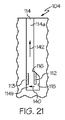
以下、用語「主軸」は、主にチューブ状の部品と、注射デバイス全体との共通の軸を画定する。主として、投与量終了通知機構の信号特徴の機能の理解に関する部品のみが本明細書で包含されるが、図面は、当該特徴を備えた注射デバイスの一部でありうる他の部品を示す場合がある。図1〜図4および図9〜図12の開示される注射デバイスは、参照することにより本明細書に組み込まれた国際公開第2012/037938A1号に開示される注射デバイスと似ているが、図6〜図8の注射デバイスは、参照することにより本明細書に組み込まれる国際公開第2005/018721号に開示される注射デバイスと似ている。 In the following, the term “main axis” defines a common axis for the primarily tubular part and the entire injection device. Although only the parts relating to the understanding of the function of the signal feature of the dose end notification mechanism are mainly included herein, the drawings may show other parts that may be part of an injection device with that feature. is there. The disclosed injection devices of FIGS. 1-4 and 9-12 are similar to the injection devices disclosed in WO 2012 / 037938A1, incorporated herein by reference. The injection device of FIGS. 6-8 is similar to the injection device disclosed in WO 2005/018721, which is incorporated herein by reference.
用語「上」および「下」ならびに「上の」および「下の」ならびに「上方」および「下方」は使用状況ではなく図面を指すものである。 The terms “above” and “below” and “above” and “below” and “upper” and “below” refer to the drawings rather than the usage.
実施形態すべてにおいて、記載されるスクリュは薬剤充填済みカートリッジ内でプランジャに当接しており、スクリュの下方への移動によって、プランジャをカートリッジ内へと移動させ、薬剤は針を通して押し出される。プランジャ、カートリッジ、および針は図示されていないが、当該技術分野において周知である。 In all embodiments, the screw described is abutting the plunger in the drug-filled cartridge, and downward movement of the screw moves the plunger into the cartridge and the drug is pushed through the needle. The plunger, cartridge, and needle are not shown but are well known in the art.
投与量セレクタおよび押しボタンは2つの別個の部品であっても、2つの機能を有する1つの部品であってもよい。 The dose selector and push button may be two separate parts or one part with two functions.
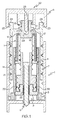
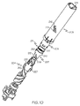
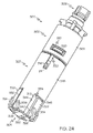
図1は、デバイスの噛み合う側に機構が配置されており、注射される投与量が設定された、本開示に係る注射デバイスの第1の実施形態を示す。ダイヤル2は第1のねじ接続21を介してハウジング1に係合し、非回転スクリュ9は第2のねじ接続22を介して用量ナット8に係合する。第1のねじ接続21のねじのピッチは第2のねじ接続22のねじのピッチよりも大きく、設定単位毎のダイヤル2の軸方向変位は、例えば、3:1の比で、いくつかの実施形態では、本開示の範囲内で3:1超または3:1未満の他の比で単位毎の用量ナット8の軸方向変位よりも大きい。投与量が設定されるとき、用量ナット8は回転し、設定投与量が注射されるとき、用量ナット8は回転しないことによって、スクリュ9は噛み合わない距離だけ単に押し下げられ、ダイヤル2は噛み合う距離だけ下に回転することになる。
FIG. 1 shows a first embodiment of an injection device according to the present disclosure in which a mechanism is arranged on the mating side of the device and the dose to be injected is set. The dial 2 engages the housing 1 via a
図1から分かるように、一次ドライバ4および二次ドライバ5は一緒に回転可能に係止され、これらの2つの部品は信号部7と一緒に、投与量設定中にダイヤル2と一緒に噛み合う距離を移動する。投与量を設定するために、投与量設定部材6が回転され、これにより、離脱可能な歯接続23、24を介してダイヤル2と、一次ドライバ4および二次ドライバ5とが回転する。同時に、用量ナット8は噛み合わない距離移動することも見て取れる。二次ドライバ5は一次ドライバ4に対して小さな軸方向距離を移動でき、信号部7のフランジ10は、投与量の注射中および注射デバイス内の薬剤からの背圧または内圧によってその後短時間だけ、一次ドライバ4の上面18と二次ドライバ5のフランジ17との間に係止される。使用者が、押しボタン20からの圧力を解放すると、ばね(図示せず)は注射デバイスの押しボタン20を周知の方法で部品5から離すように付勢する。
As can be seen from FIG. 1, the primary driver 4 and the secondary driver 5 are rotatably locked together, and these two parts are engaged together with the
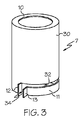
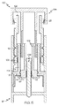
図3は、注射デバイス20の投与量終了通知機構の主な構成要素である信号部7の斜視図を示す。いくつかの実施形態では、信号部7は薄板金で作製され、図3で見ることができるように、下部には、ばねキーまたはタブ13を形成する自由端部が屈曲したばねアーム11が備えられる。ばねアーム11は信号部7の本体30から湾曲して片持ち式に延びる。したがって、タブ13を有する端部の反対側であるばねアーム11の端部は、本体30の下端部領域と一体になっている。すなわち、ばねアーム11および本体30は一体形成部品となるように一体的に形成される。信号部7の本体には本体キーまたはタブ12が設けられる。部品7の本体30は略円筒形状である。信号部7は、ばねアーム11の上かつ本体30の下に位置する円周方向に延びるスロット32を備えるように形成される。信号部7もまた、タブ12、13の間に位置する軸方向に延びるスロット34を有する。ばねアーム11に本体30に対する可撓性を付与するのは、信号部7におけるスロット32、34の提供である。図3では、ばねアーム11および本体30の湾曲は通常、注射デバイス20の主軸を中心とすることが明らかであろう。信号部7の環状フランジ10は、本体30の上端部から注射デバイス20の主軸に向けて半径方向内側に延びる。
FIG. 3 is a perspective view of the
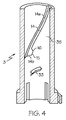
図1を再度参照すると、一次ドライバ4は、第1のねじ接続21よりもさらに大きなピッチの第3のねじ接続14で回転タワー部3と係合する。回転タワー部3は時として本明細書において「クリックタワー部」と呼ぶ。回転またはクリックタワー部3は、投与量終了通知機構(時として、単に「投与量終了機構」と呼ぶ)の別の構成要素である。回転タワー部3、一次ドライバ4、および用量ナット8は、一次ドライバ4が噛み合う距離を移動することにより、1つまたは複数の中間部品によって噛み合わない距離だけ用量ナット8が移動するように配置される。図4は、回転タワー部3の断面図を示す。一次ドライバ4と一緒に第3のねじ接続14を形成する雌ねじまたは螺旋状通路は目に見え、ねじまたは通路14が傾斜移行部16により下端部においてどのように広がっているかをはっきりと見ることができる。したがって、通路14は、細長い第1のセグメントまたは幅狭領域14aと、第1のセグメント14aの下端部にある拡大空間14bとを備える。特許請求の範囲を含め本明細書で使用する場合、用語「ねじ」は、雄ねじおよび雌ねじを包含し、用語「通路」は、雄通路(male track)および雌通路(female track)を包含する。
Referring again to FIG. 1, the primary driver 4 engages the
図4の実施形態では、ねじ14の細長い第1のセグメント14aは、クリックタワー部3の内側表面35に沿った螺旋状通路を形成する。細長い第1のセグメント14aの螺旋状通路はクリックタワー部3の主軸周りに180°未満延びる。例示的実施例では、通路14は、主軸周りに約120°延びる。その他の実施形態では、通路14と同様の通路は、所望に応じて、関連するクリックタワー部の主軸周りに180°超、または120°未満延びる。回転タワー部3もまた、内側表面35から内向きに突出する螺旋状セグメント33を有する。螺旋状セグメント33は、概して、例示的実施例では拡大空間14bとクリックタワー部3の下端部との間に位置している。図1および図2に示されるように、回転タワー部4の内側表面35から突出する2つの螺旋状セグメント33があるが、これらのうちの1つのみを図4で見ることができる。螺旋状セグメント33は、図1および図2に示すように、注射デバイスの中間部品の1つと螺合接続を形成する。
In the embodiment of FIG. 4, the elongated
ばねキー13および本体キー12は、回転タワー部3の雌ねじ14と係合し、投与量が設定されると、信号部7は回転タワー部3に対して第1の回転位置から第2の回転位置へと回転する。例示的実施例では、信号部7もまた投与量設定中に軸方向に移動する。信号部7が第1の回転位置から第2の回転位置へと回転するにつれて、キー12、13はねじ14の幅広領域14bからねじの幅狭領域14aへと移動し、これにより、本体30に対してばねアーム11を撓ませることによって、ばねアーム11を緊張させるかまたはばねアーム11の荷重を増大させる。信号部7が投与量設定中にさらに軸方向に移動すると、通路14aの螺旋状形状によって、タブ12、13が通路14a内を上方へと移動しながら、信号部7は注射デバイス20の軸周りにさらに回転する。しかしながら、信号部7のこのさらなる軸方向移動の間、ばねアーム11は、実質的に同じ量だけ荷重を印加され続けるか、または緊張させられ続けるが、これは、タブ12、13間の距離は、タブ12、13が通路14a内を上方に移動するとき実質的に一定のままであるからである。注射中、タブ12、13が通路14a内を下方に移動するように信号部7は軸方向に下方に移動するが、その結果、投与量設定中に生じた回転とは反対方向に信号部7は回転する。
When the
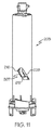
図2では、投与量の注射が開始されている。設定投与量を注射するために、押しボタン20はハウジング1の方へ押し下げられる。このボタン20の下方への移動により、投与量設定部材6とダイヤル2の間および投与量設定部材6と二次ドライバ5の間の歯接続23、24を係合解除する。さらに、組み合わせられた押しボタン20と投与量設定部材6のシャフト25が押し下げられて、二次ドライバ5の表面26と係合するため、投与量設定部材6のさらなる押し下げにより、二次ドライバ5も押し下げられる。投与量設定部材6が継続的に押されることによる二次ドライバ5の下方移動によって、さらに、摺動面接続27を介してダイヤル2を、信号部7のフランジ10により一次ドライバ4を押し下げる。このことにより、投与量を注射するために使用者により印加される力はフランジ10を通して伝達され、摩擦トルクを信号部7に印加する。
In FIG. 2, a dose injection has begun. In order to inject the set dose, the
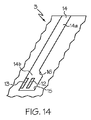
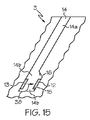
噛み合う距離を移動する部品すべて(例えば、投与量設定部材6、ダイヤル2、一次ドライバ4、二次ドライバ5、および信号部7)がゼロ位置まで完全に押されると、この移動は、ダイヤル2とハウジング1間の回転停止によって止まるが、針内の水圧抵抗によって注射中にカートリッジ内で蓄積した内圧故に、いくつかの実施形態では、ボタン20とドライバ5との間のばね(図示せず)の圧縮故に、信号部7のフランジ10ならびに一次ドライバ4および二次ドライバ5は依然として一緒に押され、摩擦トルクは依然として信号部7に印加され、フランジ10はデバイス20の内部部品4、5の間に摩擦により捕捉される。この時点で、信号部7のキー12、13は、図14に示すように、ねじ14の幅狭領域14a内の開始位置から、回転タワー部3の雌ねじ14の幅広領域14bへと図13に示す矢印36の方向に下方に移動しており、屈曲したばねアーム11は信号部7にトルクを印加し続ける。図14は、注射デバイスのストローク終了状態に対応する。しかし、信号部7のフランジ10に付与される摩擦トルクは、ばねアーム11によって印加されるトルクよりも大きく、信号部7は、カートリッジ内の圧力が消失するか、または屈曲したばねアーム11によって印加されるトルクよりも小さいフランジ10における摩擦トルクを有するレベルまで小さくなるまで回転しない。こうした状況が起こると、本体30および信号部7のフランジ10は、図15の矢印38によって示されるように第2の回転位置から第1の回転位置へと素早く回転して戻り、信号部7の本体30の本体キー12は移動して、回転タワー部3の雌ねじ14の幅広領域14bの表面15と当接し、触知および可聴信号(例えば、クリック)の両方が生じ、これによって使用者に、注射が完了し、針を皮膚から抜くことができることを知らせる。したがって、図15は、注射デバイスの投与量終了状態に対応する。
When all of the parts that move the meshing distance (eg, dose setting member 6, dial 2, primary driver 4, secondary driver 5, and signal section 7) are fully pushed to the zero position, this movement is In some embodiments, a spring (not shown) between the
新しい投与量が設定されると、信号部7は注射デバイス内で上方に移動し、キー12、13が図16に示す矢印40に示されるように一緒に押し込まれるように、タブ12は傾斜表面16に沿って進み、その後、タブ12、13は、図16および図17に示す矢印42に示されるようにねじ14の幅狭領域14aへと上方に移動する。タブ12、13が一緒に押し込まれると、可撓性アーム11はもう1度屈曲または緊張する。その時点で、信号部7に荷重が印加され、次の投与量終了状態で信号をいつでも与えることができる。
When a new dose is set, the
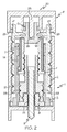
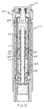
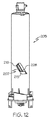
図5および図6に示す第2の実施形態では、投与量終了状態を示す機構は注射デバイスの噛み合わない側に配置される。図5は、注射される投与量が設定された注射デバイスの構成を示す。ダイヤル102は第1のねじ接続121においてハウジング101に係合し、投与ナット108は第2のねじ接続122において非回転スクリュ109に係合する。第1のねじ接続121のねじのピッチは第2のねじ接続122のねじのピッチよりも大きく、設定単位毎のダイヤル102の軸方向変位は、例えば、3:1の比で、いくつかの実施形態では、本開示の範囲内で3:1超または3:1未満の他の比で単位毎の用量ナット108の軸方向変位よりも大きい。投与量が設定されると、用量ナット108は強制的に回転される。注射中、ダイヤル102は下方へと回転して噛み合う距離を移動する。投与量設定中および注射中に噛み合わない距離を用量ナット108と一緒に移動する中間部品104は、ダイヤル102と用量ナット108との間に配置されて、注射中にその間に力を伝達する。中間部品104の機能は、使用者により印加された力を伝達することと、直線変位を抑えることである。注射中、用量ナットは部品104によって下に移動され、スクリュ109を噛み合わない距離だけ押し下げる。
In the second embodiment shown in FIGS. 5 and 6, the mechanism for indicating the dose end state is arranged on the non-meshing side of the injection device. FIG. 5 shows the configuration of an injection device in which the dose to be injected is set. The
投与量を設定するために、用量ナット108に回転可能に係止された投与量設定部材106が回転し、部品102、106間の歯接続123のため、これによりダイヤル102もまた回転し、ダイヤル102が投与量設定部材106と一緒にハウジング101から噛み合う距離だけ持ち上がる。中間部品104および用量ナット108は信号部107と一緒に噛み合わない距離を上方に移動する。用量ナット108は中間部品104に対して小さな軸方向距離を移動でき、信号部107のフランジ110は、投与量の注射中および注射デバイス内の薬剤からの背圧または内圧によってその後短時間だけ、中間部品104の下面118と用量ナット108のフランジ117との間に係止または摩擦により捕捉される。ばね(図示せず)は注射デバイスの押しボタン120を周知の方法で部品102から離れて付勢する。
In order to set the dose, the
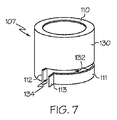
図7は、第1の実施形態の信号部7と類似の信号部107の斜視図を示す。信号部107は、注射デバイス120の投与量終了通知機構の主な構成要素である。いくつかの実施形態では、信号部107は薄板金で作製され、図7で見ることができるように、下部には、ばねキーまたはタブ113を形成する自由端部が屈曲したばねアーム111が備えられる。ばねアーム111は信号部107の本体130から湾曲して片持ち式に延びる。したがって、タブ113を有する端部の反対側であるばねアーム111の端部は、本体130の下端部領域と一体になっている。すなわち、ばねアーム111および本体130は一体形成部品となるように一体的に形成される。信号部107の本体130には本体キーまたはタブ112が設けられる。部品107の本体130は略円筒形状である。信号部107は、ばねアーム111の上かつ本体130の下に位置する円周方向に延びるスロット132を備えるように形成される。信号部107もまた、タブ112、113との間に位置する軸方向に延びるスロット134を有する。ばねアーム111に本体130に対する可撓性を付与するのは、信号部107におけるスロット132、134の提供である。ばねアーム111および本体130の湾曲は通常、注射デバイス120の主軸を中心とする。信号部107の環状フランジ110は、本体130の上端部から注射デバイス120の主軸に向けて半径方向内側に延びる。
FIG. 7 is a perspective view of a
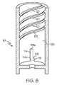
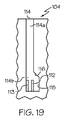
図8は、本実施形態では、デバイスの外部ハウジングも成す回転ハウジング101の断面図を示す。ハウジング101の内側表面135は、細長い第1のセグメント114aを有する通路114と、第1のセグメント114aの下端部にある拡大または幅広空間114bとを備えるように形成される。第1の実施形態の通路14の部分14aの螺旋状経路とは異なり、通路114の細長部分114aはまっすぐでハウジング101に対して軸方向に延びる。通路114は傾斜移行部116を介して下端部が広がっている。ばねキー113および本体キー112は、ハウジング101の雌通路114と係合し、投与量が設定されると、信号部107は第1の回転位置から第2の回転位置へと回転する。例示的実施例では、信号部107もまた投与量設定中に軸方向に移動する。信号部107が第1の回転位置から第2の回転位置へと回転するにつれて、キー112、113は通路114の幅広領域114bから通路114の幅狭領域114aへと移動し、これにより、本体130に対してばねアーム111を撓ませることによって、ばねアーム111を緊張させるかまたはばねアーム111の荷重を増大させる。信号部107が投与量設定中にさらに軸方向に移動すると、信号部は、通路114aがまっすぐで軸方向に延びるため第2の回転位置に留まる。注射中、タブ112、113が通路114a内を下方に移動するように信号部107は軸方向に下方に移動する。
FIG. 8 shows a cross-sectional view of the
図6では、投与量の注射が開始されている。設定投与量を注射するために、押しボタン120はハウジング101の方へ押し下げられる。この下方への移動により、投与量設定部材106とダイヤル102間の歯接続123を係合解除し、押しボタン120は摺動面126においてダイヤル102と係合するため、さらに下方へと押しボタン120を押すことで、ダイヤル102も押し下げる。押しボタン120が継続的に押されることによるダイヤル102の下方移動によって、信号部107のフランジ110により中間部品104および用量ナット108も押し下げる。このことにより、投与量を注射するために使用者により印加される力はフランジ110を通して伝達され、摩擦トルクを信号部107に印加する。
In FIG. 6, a dose injection has begun. To inject a set dose,
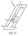
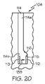
投与量設定部材106およびダイヤル102がゼロ位置まで完全に押されると、この移動は、ダイヤル102とハウジング101間の回転停止によって止まるが、針内の水圧抵抗によって注射中にカートリッジ内で蓄積した内圧故に、信号部107のフランジ110、中間部品104、および用量ナット108のフランジ117は依然として一緒に押され、摩擦トルクは依然として信号部107に印加され、フランジ110はデバイス120の内部部品104、108の間に摩擦により捕捉される。この時点で、信号部107のキー112、113は、図19に示すように、通路114の幅狭領域114a内の開始位置から、ハウジング101の雌通路114の幅広領域114bへと図18に示す矢印136の方向に下方に移動しており、屈曲したばねアーム111は信号部107にトルクを印加し続ける。図19は、注射デバイスのストローク終了状態に対応する。しかし、信号部107のフランジ110に付与される摩擦トルクは、ばねアーム111によって印加されるトルクよりも大きく、信号部107は、カートリッジ内の圧力が消失するか、または屈曲したばねアーム111によって印加されるトルクよりも小さいフランジ110における摩擦トルクを有するレベルまで小さくなるまで回転しない。こうした状況が起こると、本体130および信号部107のフランジ110は、図20の矢印138によって示されるように第2の回転位置から第1の回転位置へと素早く回転して戻り、信号部107の本体130の本体キー112は移動して、ハウジング101の雌通路114の幅広領域114bの表面115と当接し、触知および可聴信号(例えば、クリック)の両方が生じ、これによって使用者に、注射が完了し、針を皮膚から抜くことができることを知らせる。したがって、図20は、注射デバイスの投与量終了状態に対応する。
When the
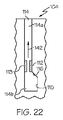
新しい投与量が設定されると、信号部107は注射デバイス内で上方に移動し、キー112、113が図21に示す矢印140に示されるように一緒に押し込まれるように、タブ112は傾斜表面116に沿って進み、その後、キー112、113は、図21および図22に示す矢印142に示されるように通路114の幅狭領域114aへと上方に移動する。タブまたはキー112、113が一緒に押し込まれると、可撓性アーム111はもう1度屈曲または緊張する。その時点で、信号部107に荷重が印加され、次の投与量終了状態で信号をいつでも与えることができる。本実施形態の特徴はデバイスの噛み合わない側に配置されているため、使用者が、機構に全荷重を印加し、次の信号のために準備する第1の実施形態の場合よりも多い投与量を設定しなければならない。すなわち、タブ112、113を通路114の幅広領域114bから幅狭領域114aへと上方に移動させるためには、タブ12、13を通路14の幅広領域14bから幅狭領域14aへと上方に移動させるために必要とされる投与量設定部材6の回転よりも多くの投与量設定部材106の回転が必要となる。
When a new dose is set, the
図9〜図12は、機能に関しては第1の実施形態と同等であるが、トルクばね211は信号部207と一体でない別個の部品である、注射デバイス220の噛み合う側に配置された投与量終了信号または通知機構の第3の実施形態を示す。トルクばね211は、一端が信号部207に固定され、他端が二次ドライバ205に固定される。
9 to 12 are functionally equivalent to the first embodiment, but the
図10に示されるように、非上昇回転タワー部203は4始点型ねじ214を備える。4始点型ねじ214は、高いピッチを有し、始点のうちの2つは傾斜移行部216を介して下端部が広がっている215。成形プロセスを容易にするために、拡大領域215は回転タワー部203における切抜き部として作成される。信号部207および一次ドライバ204は互いに軸方向に従うが、互いに対して限られた角度だけ回転可能である。信号部207は、回転タワー部203の一端が広がっているねじ214の4つの始点のうちの2つと係合する2つのねじセグメント228を有し、一次ドライバ204は、残りの2つの始点と係合する2つのねじセグメント227を有する。信号部207のねじセグメント228は、投与量が設定される前に拡大領域215内に配置される。この時点で、トルクばね211は、投与量が設定されるときよりも弱く緊張するかまたは小さい荷重が印加される。換言すれば、例示的実施例において、ばね211は常にいくらか緊張しており、緊張レベルは投与量が設定されるときに増大する。図9において、ハウジング201の内部領域における部品間の相対位置を見ることができる。投与量エレクタ(elector)206を回転することにより投与量が設定されるとき、信号部207および一次ドライバ204の両方が回転タワー部203に対して上昇し、その結果、信号部207のねじセグメント228は、傾斜移行部216を介してねじ214の幅狭領域へと回転し、それにより信号部207は一次ドライバ204に対して、トルクばね211の付勢トルクにより第1の回転位置から第2の回転位置までの角度だけ回転する。この相対回転はさらにトルクばね211を緊張させるかまたは荷重を増大させる。
As shown in FIG. 10, the non-ascending
設定投与量を注射するために、使用者は押しボタン220を押し、それによって、押しボタン220の最初の移動後、押す力は二次ドライバ205に伝達される。信号部207は、デバイスの主軸に向かって突出し、一次ドライバ204の表面218と二次ドライバ205の突出部217との間に位置する複数の突出部210を有する(図9参照)。その結果、押す力は二次ドライバ205から突出部210を通って一次ドライバ204へ伝達される。力は一次ドライバ204から複数の中間部品を通ってスクリュ209へ、そしてカートリッジのピストンへと伝達される。押しボタン220がゼロ位置またはストローク終了位置まで押された直後に、使用者から押しボタン220への継続している圧力と、例えば、カートリッジ内のゴムピストンの圧縮および針内の水圧抵抗によるカートリッジからの内圧または背圧によって、ドライバ204、205間の信号部207の突出部210は圧迫され、信号部207が初期位置(すなわち、投与量が設定される前の第1の回転位置)へと回転して戻るのを防止する。したがって、この時点で、突出部210はデバイス220の内部部品204、205間に摩擦して捕捉される。
To inject the set dose, the user presses the
図11では、信号部207のセグメント228がねじ214の拡大領域215まで下方に移動するが、信号部207は依然として回転がロックされていることが見て取れる。圧縮されたピストンによりゆっくりと残りの投与量が針から出、信号部207の突出部210への圧力が消えて力が十分に小さくなると、トルクばね211によって信号部207に印加されたトルクから信号部207を保持できないので、信号部207は回転し始める。突出部210は、二次ドライバ205の突出部217からの圧力から解放されるのに十分な大きさの角度回転すると、信号部207の回転は、第2の回転位置から第1の回転位置へ戻る回転の間加速し、信号部207の軸面213は移動して、一次ドライバ204の軸面212に当接し、可聴信号または触知信号(例えば、クリック)を生成する。これは、投与量が完全に注射され、針を皮膚から引き抜くことが可能であることの使用者への信号である。図12では、信号部207のねじセグメント228のうちの1つが、図11のセグメント228の位置と比べて、対応する拡大領域215の反対側へと回転することが見て取れる。例示的実施例では、軸面213は、信号部207の下部領域に設けられたノッチの境界の一部として機能する。
In FIG. 11, it can be seen that the
前述に基づいて、注射デバイス20、120、220はそれぞれ、それぞれの信号部7、107、207を備えた投与量終了通知機構を有することを理解すべきである。信号部7、107、207はそれぞれ、第1の回転位置から第2の回転位置まで対応するハウジング1、101、201に対して軸周りに回転し、投与量を設定する際に、対応するハウジング1、101、201に対する投与量設定部材6、106、206の回転によって、対応するばね(例えば、ばねアーム11、111およびねじりばね211)に対する荷重を増大させる。注射中に内圧が注射デバイス20、120、220内で蓄積するため、それぞれの信号部7、107、207は、第2の回転位置においてそれぞれの注射デバイス20、120、220の第1の内部部品と第2の内部部品と(例えば、4、5;104、108;および204、205)の間に摩擦によって捕捉される。注射中に内圧が十分な量消失した後、信号部7、107、207は対応する荷重が印加されたばね11、111、211の付勢により解放されてそれぞれハウジング1、101、201に対して回転し、第2の回転位置から第1の回転位置へと戻る。それぞれの信号部7、107、207が第1の回転位置に到達すると、信号部7、107、207それぞれの一部(例えば、タブ12、112、および軸面213)が移動して対応する表面(例えば、表面15、115、212)と接触し、投与量終了状態に達したことを示す触知または可聴フィードバックが生成される。
Based on the foregoing, it should be understood that the
いくつかの実施形態では、適切な回転が注射デバイスの1つまたは複数の他の内部部品に対して起こった場合、信号部は外部ハウジングに対して回転する必要がない。 In some embodiments, the signal portion need not rotate relative to the outer housing if proper rotation occurs relative to one or more other internal components of the injection device.
ここで図23A、図23B、および図24を参照すると、投与量終了信号または通知機構300の第4の実施形態は、コネクタロック302、投与量終了クリックチューブまたは信号部307、およびコネクタ304を備える。コネクタロック302は、コネクタロック302のチューブ状セクション308によって保持されるボタン連結構造306を備える。チューブ状セクション308は、貫通形成された1組のスナップフィンガ受容ウインドウ310を有する。例示的実施例では、3つのウインドウ310はチューブ状セクション308に設けられ、各ウインドウ310は略矩形形状である。
Referring now to FIGS. 23A, 23B, and 24, a fourth embodiment of a dose end signal or
コネクタ304は、略矩形のばねアームを受容するウインドウ314が貫通して形成された主要チューブ状部分312を備える。ばねアーム311は、チューブ状部分312と一体形成され、ウインドウ314内へと略軸方向上方に延びる。つまみまたはラグ316はバネアーム311の上部の自由端部に設けられる。1組のスナップフィンガ318は、部分312と一体形成され、部分312から略軸方向上方に延びる。例示的実施例では、3つのスナップフィンガ318が設けられる。各スナップフィンガ318は、傾斜した隆起部またはフランジ320をその上端部に備える。コネクタ304およびコネクタロック302が図24に示されるように一緒に組み立てられると、コネクタ304のフランジ320はコネクタロック302の対応するウインドウ310に受容される(1つのみのフランジ320および1つのウインドウ310が図24に示される)。
The
コネクタ304は、チューブ状部分312の下端部領域と一体形成された1組のパッド322を有する。例示的実施形態では、チューブ状部分312の円周周りに互いに実質的に等距離で離間された3つのパッド322がある。コネクタ304はさらに、対応するパッド322から半径方向外側に延びて、ドライバ要素(図示せず)またはハウジング(図示せず)等の関連する注射デバイスの別の部品(図示せず)に形成された相補的な形状の螺旋状溝と係合する螺旋状雄ねじセグメント324を有する。コネクタ304は、チューブ状部分312の下端部領域の内部表面から半径方向内側に延びる螺旋状雌ねじセグメント326を有する。ねじ326は、ドライバ要素(図示せず)等の関連する注射デバイスの別の部品(図示せず)に形成された相補的な形状の螺旋状溝と係合する。
The
信号部307は、3つのまっすぐな軸方向に延びるラグ受容スロット330が貫通形成されたチューブ状主要部分328を備える。スロット330は部分328の上端部に位置する。信号部307はさらに、部分328と一体形成される1組のアーム332を有する。アーム332は部分328の底端部から軸方向に延びる。例示的実施例では、図23Aおよび図23Bに示されるように信号部307の下端部における3つのパッド受容ノッチ334を画定するように離間される3つのアーム332がある。信号部307は、それぞれが対応するアーム332の底端部領域から略半径方向外側に延びて、ドライバ要素(図示せず)またはハウジング(図示せず)等の関連する注射デバイスの別の部品(図示せず)に形成された相補的な形状の螺旋状溝と係合する螺旋状雄ねじセグメント336を有する。
The
投与量終了信号機構300は、スナップフィンガ318が信号部307の上端部を越え、コネクタロック302の穴または内部領域の中へと延びるように、コネクタ304を信号部307の内部領域または穴を通して上方に挿入することによって組み立てられる。ウインドウ310内におけるフランジ320の受容によって、信号部307がコネクタロック302の下部環状縁部338とコネクタ304のパッド322との間に捕捉された状態でコネクタロック302およびコネクタ304を一緒にしっかりと固定する。パッド322は信号部307のノッチ334に受容される。
The dose
例示的実施例では、信号部307の外径は、コネクタロック302のチューブ状セクション308の外径と実質的に等しい。さらに、機構が組み立てられると、ばねアーム311の上端部にあるラグ316は、図24に示すように、信号部307のスロット330のうちの1つに受容される。3つのスロット330を信号部307に提供することよって、コネクタ304が信号部307に挿入できる3つの可能な配向がある。3つのスロット330のうちどのスロット330をラグ316が塞ぐかにかかわらず、投与量終了機構300は実質的に同じように動作する。
In the exemplary embodiment, the outer diameter of
パッド322はそれぞれ、図23に示すように、軸方向停止縁部または表面340と、軸方向クリック縁部または表面342とを備える(図23Aおよび図23Bにおいて、縁部340はパッド322のうちの1つで見ることができ、縁部342は別のパッド322で見ることができる)。ノッチ334はそれぞれ、軸方向停止縁部または表面344と、軸方向クリック縁部または表面346とによって画定される。縁部344、346は信号部307の各アーム332の両側に画定される。パッド322の縁部340、342およびアーム332の縁部344、346はそれぞれ、実質的にまっすぐで、互いに略平行に延びる。
Each
パッド322は、機構300の円周方向においてパッド322が受容される対応するノッチ334よりも小さい。すなわち、各パッド322の縁部340、342間の円弧の長さは、各ノッチの縁部344、346間の円弧の長さよりも小さい。したがって、各パッドの縁部342は、対応するアーム332の対応縁部346に当接し、円周方向の間隙が各パッド322の縁部340と対応するアーム332のそれぞれの縁部344との間に存在する。これらの円周方向の間隙は、信号部307がコネクタ304およびコネクタロック302に対して機構300の主軸周りにどのくらいの回転できるかを規定する。したがって、注射デバイスの投与量設定中、信号部307は、パッド322の縁部342がアーム332の縁部346に当接する第1の回転位置とパッド322の縁部342がアーム332の縁部346から離れるように移動し、パッド322の縁部340がアーム332の縁部344に近付くかまたは当接する第2の回転位置との間を回転可能である。
The
いくつかの実施形態では、信号部307が図24に示される第1の回転位置にあるとき、ばねアーム311は荷重が印加されず、図23Aおよび図23Bに示す実線位置にある。その他の実施形態では、信号部307が第1の回転位置にあるとき、ばねアーム311は、わずかに荷重が印加されるようにわずかに屈曲または緊張する。信号部307が第1の回転位置から第2の回転位置へと回転するにつれて、ばねアーム311はウインドウ314内で屈曲して図23Aおよび図23Bに示す点線位置となる。点線位置において、ばねアーム311は、実線位置よりも大きい量緊張するかまたは荷重が印加される。
In some embodiments, when the
上述の先の実施形態の場合と同様に、注射中および注射デバイスのボタンがそのゼロ位置まで押された後、関連する注射デバイス内の内圧は、第2の回転位置から第1の回転位置へと戻る信号部307の回転を防ぐ注射デバイスの挟持力をもたらす。信号部307はさらに、ねじセグメント336が注射デバイスの別の部品(図示せず)に受容されることにより、注射サイクルの一部の前およびその間第2の回転位置で保持される。したがって、ボタンがそのゼロ位置まで押された後、信号部307は、注射デバイスの内圧が十分消失するまで、注射中第2の回転位置に留まる。
As in the previous embodiment described above, the internal pressure in the associated injection device is changed from the second rotational position to the first rotational position during injection and after the button of the injection device is pushed to its zero position. This brings about a holding force of the injection device which prevents the rotation of the
投与量設定中かつボタンがゼロ位置に到達する前は、信号部336の3つのねじセグメント336は、上で開示された第1の実施形態(図13〜図17参照)の部品3の幅狭部分14aと同様に、6始点型ねじ付き部品のそれぞれの螺合溝の幅狭部分に受容される。ねじセグメント336を受容する螺合溝は、部品3の拡大空間14bと同様の拡大空間を有する。コネクタ304のねじセグメント324は、6始点型ねじ付き部品の他の3つの螺合溝に受容されるが、これらの3つの螺合溝はいかなる拡大空間も有していない。したがって、ねじセグメント336は6始点型ねじ付き部品の対応する螺合溝の拡大空間に配置されると、信号部307はコネクタ304およびコネクタロック302に対して回転できる。しかし、上記で説明したように、信号部307は、注射デバイスの内圧が十分消失するまで、第2の回転位置から第1の回転位置に戻るように回転し始めない。
During the dose setting and before the button reaches the zero position, the three
図23Bに示されるように、単一の部品307は、主要部分328の上端部に隣接して半径方向内側に突出する3つのタブ350を有する。図23Aに示されるように、コネクタロック302は、チューブ状セクション308の底端部に隣接して半径方向内側に突出する3つの突出部352を有する。コネクタロックはさらに、突出部352と一体形成され、チューブ状セクション308の底端部を越えて軸方向に延びる3つのストッパタブ354を有する。図23Bに示されるように、コネクタ304は、主要チューブ状部分312の頂部領域にスナップフィンガ318間に延びる3つの縁部356を有する。注射中、第2の回転位置から第1の回転位置へ戻る信号部307の回転を阻止する挟持力は、コネクタロック302の突出部352とコネクタ304の縁部356との間に挟持されるタブ350によって生成される。さらに、信号部307が第2の回転位置にあるとき、タブ350はストッパ354に当接し、信号部307が第1の回転位置にあるとき、タブ350はストッパ354から離間される。
As shown in FIG. 23B, the
注射デバイス内の内圧が十分に消失した後は、信号部307のタブ350に作用する挟持力は、ばねアーム311の力から信号部307を保持する十分な強さではなくなり、所与の実施形態で場合によっては、ばねアーム311はその比較的強く緊張しているかまたは荷重が印加される位置(例えば、図23のばねアーム311の点線位置)から荷重が印加されていないかまたはわずかに荷重が印加された位置(例えば、図23のばねアーム311の実線位置)へと移動する。ばねアーム311がこのようにして移動すると、ラグ316によって信号部307に印加されたトルクによって、信号部307を駆動してコネクタロック302およびコネクタ304に対して第2の回転位置から第1の回転位置へと戻すように回転させる。信号部307が第1の回転位置に到達すると、信号部307のアーム332の縁部346はコネクタ304のパッド322の縁部342に接触して、触知および可聴信号(例えば、クリック)の両方が生じ、これによって使用者に、注射が完了し、針を皮膚から抜くことができることを知らせる。したがって、図24は、注射デバイスの投与量終了状態に対応する。
After the internal pressure in the injection device has sufficiently disappeared, the clamping force acting on the
機構300の例示的実施形態は、信号部307のノッチ334に受容されるコネクタ304のパッド322を有するが、パッド322以外の突出部およびノッチ334以外の空間も本開示の範囲内であることを理解すべきである。例えば、いくつかの実施形態では、信号部307における、信号部307全体を通って延在しない1つまたは複数のポケットまたは凹みがノッチ334の代わりとして十分である。さらに、いくつかの実施形態では、支柱、フィンガ、ラグ、突起等の1つまたは複数の突出部がパッド322の代わりとして十分である。信号部307がばねアーム311等の好適な付勢要素の付勢によって第1の回転位置まで戻るとすぐに、信号部307の表面または縁部が移動してコネクタ304の表面または縁部に接触する限り、好適な触知または可聴フィードバックが本開示の対応する注射デバイス内で生成される。
The exemplary embodiment of the
例示的実施例では、ばねアーム311およびウインドウ314はコネクタ304の一部として備えられる。代替的実施形態では、ばねアーム311および対応するウインドウ314は代替となるコネクタロック302に設けられる。このような実施形態では、コネクタロックのばねアーム311を保持する部分は信号部307の穴に挿入される。代替的にまたは加えて、信号部307は、ラグ316を、主要部分328全体を通って延びるスロット330ではなく内部に受容する溝を有する。さらに、代替的にまたは加えてラグ316はばねアーム311から省略され、信号部307は、ばねアーム311に係合してばねアーム311を実線位置から点線位置へと移動させる、内向きに延びる突出部を有する。このような実施形態では、信号部307のスロット330または溝は必要とされない。
In the exemplary embodiment,
特定の例示的実施形態が上記で詳細に説明されたが、なお本明細書に記載される本開示の範囲および趣旨内であり、以下の特許請求の範囲に規定される多くの実施形態、変形形態、および改変形態が可能である。 While certain exemplary embodiments have been described in detail above, many embodiments, variations, which are still within the scope and spirit of the present disclosure as described herein, are defined in the following claims. Forms and modified forms are possible.
Claims (35)
ハウジングと、
注射される投与量を設定するために前記ハウジングに対して移動可能である投与量設定部材と、
第1の回転位置から第2の回転位置まで前記注射デバイス内の表面に対して軸周りに回転し、前記ハウジングに対する前記投与量設定部材の回転によって投与量が設定されたときに、ばねへの荷重を増大させる、信号部と、
を備え、注射中、内圧が前記注射デバイス内で蓄積するため、前記信号部は、前記第2の回転位置において前記注射デバイスの第1の内部部品と第2の内部部品との間に摩擦によって捕捉され、注射中に前記内圧が十分な量消失した後は、前記信号部は荷重が印加された前記ばねの付勢により回転して、前記第2の回転位置から前記第1の回転位置へと戻り、前記信号部が前記第1の回転位置に到達すると、前記信号部の一部が移動して前記表面と接触し、投与量終了状態に達したことを示す触知または可聴フィードバックが生成される、注射デバイス。 An injection device for injecting a medicament,
A housing;
A dose setting member movable relative to the housing to set a dose to be injected;
When rotating from the first rotational position to the second rotational position about an axis relative to the surface in the injection device and the dosage is set by rotation of the dosage setting member relative to the housing, A signal part for increasing the load;
And during injection, the internal pressure builds up in the injection device, so that the signal portion is frictionally between the first internal component and the second internal component of the injection device in the second rotational position. After a sufficient amount of the internal pressure disappears during the injection and the injection, the signal portion rotates by the bias of the spring to which a load is applied, and moves from the second rotational position to the first rotational position. When the signal part reaches the first rotational position, a part of the signal part moves to contact the surface and generates a tactile or audible feedback indicating that a dose end state has been reached. An injection device.
略チューブ状であり、内側表面に形成された通路を有し、前記通路は、細長い第1のセグメントおよび前記第1のセグメントの端部にある拡大空間を有する、回転タワー部と、
注射される投与量を設定するために前記回転タワー部に対して移動可能である投与量設定部材と、
前記回転タワー部の内部領域に配置され、前記回転タワー部によって画定される軸に沿って移動可能であり、前記通路内に受容される第1のタブを有する本体を有し、前記本体から片持ち式に支持されたばねアームを有し、前記ばねアームは、前記回転タワー部により画定される前記軸周りに湾曲して延び、第2のタブを有する遠位端部を有する、信号部と
を備え、前記投与量を設定するための前記投与量設定部材の移動によって、前記信号部の前記本体は第1の回転位置から第2の回転位置へと前記回転タワー部に対して軸周りに回転するため、前記第1のタブが前記第2のタブへと移動して前記ばねアームの荷重を増大させ、
投与量設定後かつ投与量注射前に、前記第1のタブおよび前記第2のタブは前記回転タワー部の前記通路の前記細長い第1のセグメント内に配置され、注射中、前記第1のタブおよび前記第2のタブは前記拡大空間へと移動し、
内圧が注射中に前記注射デバイス内で蓄積した結果、前記第1のタブおよび前記第2のタブが前記拡大空間内で広がって離れることを防止するように、前記信号部は、前記第2の回転位置において前記注射デバイスの第1の内部部品と第2の内部部品との間に捕捉され、
前記内圧が十分な量消失するのに応じて、前記ばねアームが撓んで、前記第1のタブおよび前記第2のタブを離すように広げるため、前記信号部の前記本体が前記第2の回転位置から前記第1の回転位置へと戻るように回転して、前記第1のタブと前記回転タワー部の前記通路の前記拡大空間内の表面とがカチっと音を出し、投与量終了状態に達したという信号を出す、投与量終了通知機構。 A dose completion notification mechanism for an injection device used to inject a drug, comprising:
A rotating tower portion that is generally tubular and has a passage formed in an inner surface, the passage having an elongated first segment and an enlarged space at an end of the first segment;
A dose setting member movable relative to the rotating tower to set the dose to be injected;
A body disposed in an interior region of the rotating tower portion, movable along an axis defined by the rotating tower portion, and having a first tab received in the passage; A signal arm having a spring arm supported in a hand-held manner, said spring arm extending curvedly about said axis defined by said rotating tower portion and having a distal end having a second tab; And the body of the signal portion rotates about an axis relative to the rotating tower portion from a first rotational position to a second rotational position by movement of the dosage setting member to set the dosage. The first tab moves to the second tab to increase the load on the spring arm;
After dose setting and prior to dose injection, the first tab and the second tab are disposed within the elongated first segment of the passage of the rotating tower section, and during the injection, the first tab And the second tab moves into the enlarged space;
In order to prevent the first tab and the second tab from spreading apart in the enlarged space as a result of internal pressure accumulating in the injection device during injection, the signal portion is Captured between a first internal part and a second internal part of the injection device in a rotational position;
As the internal pressure disappears by a sufficient amount, the spring arm bends and widens away from the first tab and the second tab, so that the body of the signal portion is rotated in the second rotation. Rotating back from the position to the first rotational position, the first tab and the surface of the passage in the rotating tower section make a clicking sound, and the dosage end state Dose end notification mechanism that signals that it has reached
ばねと、
投与量設定中に第1の位置から第2の位置へと回転移動して前記ばねの荷重を増大させ、信号部の一部が、前記第2の位置において、注射中に前記カートリッジ内に蓄積する内圧により、前記少なくとも2つの部材の表面間に摩擦により捕捉される、信号部と
を備え、前記内圧が十分な量消失した後は、前記少なくとも2つの部材は、前記信号部の一部を解放し、それによって前記信号部は前記ばねの付勢によって前記第2の位置から前記第1の位置へと戻るように回転し、前記信号部は、前記注射デバイスの第2の表面と接触して、投与量終了状態に達したことを示す触知または可聴フィードバックを提供する第1の表面を有する、投与量終了機構。 A dose termination mechanism for use with the injection device having at least two members that receive an axial force when the injection device operates to push a drug out of the cartridge of the injection device;
Springs,
During the dose setting, the spring load is increased by rotating from the first position to the second position, and a part of the signal part accumulates in the cartridge during the injection in the second position. A signal portion captured by friction between the surfaces of the at least two members due to the internal pressure, and after the internal pressure has disappeared by a sufficient amount, the at least two members are configured to have a part of the signal portion. Releasing, whereby the signal portion rotates back from the second position to the first position by biasing of the spring, and the signal portion contacts the second surface of the injection device. And a dose termination mechanism having a first surface that provides tactile or audible feedback indicating that a dose termination condition has been reached.
ウインドウが貫通形成された略円筒形部分を有し、前記円筒形部分と一体形成され、前記ウインドウ内へと略軸方向に延びるばねアームを有し、前記略円筒形部分から半径方向に突出する少なくとも1つの突出部を有する、第1の部品と、
第1の回転位置と第2の回転位置との間を回転するように前記第1の部品に連結され、ばねアーム係合部分を有し、前記少なくとも1つの突出部を中に受容する少なくとも1つの空間を有する、信号部と
を備え、投与量を設定するために前記注射デバイスを使用する間、前記信号部は前記第1の回転位置から前記第2の回転位置へと回転し、前記ばねアーム係合部分は前記ばねアームに作用して、前記ばねアームを前記ウインドウ内に移動させ、前記ばねアームの荷重を増大させ、
薬剤を注射するために前記注射デバイスを使用する間、内圧が注射中に前記注射デバイス内で蓄積し、その結果、前記信号部は前記第2の回転位置で維持されるため、前記ばねアームがその荷重を減少させるように移動することが防止され、
前記内圧が十分な量消失するのに応じて、前記ばねアームが撓み、前記ばねアーム係合部分に作用して、前記信号部は前記第2の回転位置から前記第1の回転位置へと戻るように回転して、前記信号部の縁部と前記信号部の前記少なくとも1つの空間内に受容された前記突出部の表面とがカチっと音を出す、投与量終了機構。 A dose termination mechanism for use with an injection device comprising:
A window has a generally cylindrical portion through which is formed, and has a spring arm that is integrally formed with the cylindrical portion and extends substantially axially into the window, and projects radially from the generally cylindrical portion. A first part having at least one protrusion;
At least one coupled to the first component for rotation between a first rotational position and a second rotational position, having a spring arm engagement portion and receiving the at least one protrusion therein A signal portion having two spaces, wherein the signal portion rotates from the first rotational position to the second rotational position while using the injection device to set a dose, and the spring An arm engaging portion acts on the spring arm to move the spring arm into the window, increasing the load on the spring arm;
While using the injection device to inject medication, internal pressure builds up in the injection device during injection so that the signal portion is maintained in the second rotational position so that the spring arm is It is prevented from moving to reduce its load,
As the internal pressure disappears by a sufficient amount, the spring arm bends and acts on the spring arm engaging portion, and the signal portion returns from the second rotational position to the first rotational position. The dose ending mechanism in which the edge of the signal part and the surface of the protrusion received in the at least one space of the signal part make a clicking sound.
Applications Claiming Priority (3)
| Application Number | Priority Date | Filing Date | Title |
|---|---|---|---|
| US201462008559P | 2014-06-06 | 2014-06-06 | |
| US62/008,559 | 2014-06-06 | ||
| PCT/US2015/034128 WO2015187913A1 (en) | 2014-06-06 | 2015-06-04 | Rotatable end of dose feedback mechanism |
Publications (1)
| Publication Number | Publication Date |
|---|---|
| JP2017516632A true JP2017516632A (en) | 2017-06-22 |
Family
ID=53433298
Family Applications (1)
| Application Number | Title | Priority Date | Filing Date |
|---|---|---|---|
| JP2017515881A Withdrawn JP2017516632A (en) | 2014-06-06 | 2015-06-04 | The rotatable end of the dose feedback mechanism |
Country Status (12)
| Country | Link |
|---|---|
| US (1) | US20170095613A1 (en) |
| EP (1) | EP3151887A1 (en) |
| JP (1) | JP2017516632A (en) |
| KR (1) | KR20160147039A (en) |
| CN (1) | CN106456902A (en) |
| AU (1) | AU2015269605A1 (en) |
| CA (1) | CA2946350A1 (en) |
| EA (1) | EA201692218A1 (en) |
| MA (1) | MA39919A (en) |
| MX (1) | MX2016016128A (en) |
| WO (1) | WO2015187913A1 (en) |
| ZA (1) | ZA201607104B (en) |
Families Citing this family (9)
| Publication number | Priority date | Publication date | Assignee | Title |
|---|---|---|---|---|
| CN105492044B (en) * | 2013-09-03 | 2021-03-09 | 赛诺菲 | Drive mechanism and injection device with same |
| GB201616712D0 (en) | 2016-09-30 | 2016-11-16 | Owen Mumford Ltd | Injection devices |
| EP3849635B1 (en) * | 2018-09-12 | 2025-11-26 | Becton, Dickinson and Company | Universal connection device for pen injectors |
| GB2577095B (en) * | 2018-09-13 | 2021-01-06 | Owen Mumford Ltd | Injection device |
| DE102019214094A1 (en) | 2019-09-17 | 2021-03-18 | Zf Friedrichshafen Ag | Fixing agent for heavy gear parts |
| GB2590494A (en) * | 2019-12-20 | 2021-06-30 | Maguire Kevin | A dispensing device |
| US20230166045A1 (en) * | 2020-04-23 | 2023-06-01 | Sanofi | Injection Device with an Electronic Detector |
| KR102331962B1 (en) * | 2021-07-26 | 2021-12-02 | 주식회사 노투스 | Multi-needle assembly to ensure uniform injection performance |
| CN119770801B (en) * | 2025-01-13 | 2025-12-05 | 苏州森恩博医疗科技有限公司 | A torsion spring anti-collision device for an injection pen |
Family Cites Families (13)
| Publication number | Priority date | Publication date | Assignee | Title |
|---|---|---|---|---|
| US5271527A (en) * | 1992-04-02 | 1993-12-21 | Habley Medical Technology Corporation | Reusable pharmaceutical dispenser with full stroke indicator |
| ATE197408T1 (en) | 1998-01-30 | 2000-11-11 | Novo Nordisk As | A SYRINGE |
| WO2005018721A1 (en) | 2003-08-12 | 2005-03-03 | Eli Lilly And Company | Medication dispensing apparatus with triple screw threads for mechanical advantage |
| BRPI0607012A2 (en) * | 2005-01-25 | 2009-12-01 | Novo Nordisk As | injection device |
| US9757525B2 (en) * | 2009-12-01 | 2017-09-12 | Becton, Dickinson And Company | Injection pen with dial back and last dose control |
| EP2588162B1 (en) * | 2010-07-02 | 2020-01-01 | Sanofi-Aventis Deutschland GmbH | Safety device for a pre-filled syringe and injection device |
| CN103189084B (en) | 2010-09-24 | 2015-03-25 | 伊莱利利公司 | A gearing mechanism for a dose delivery device |
| CA2856915C (en) | 2011-11-25 | 2015-12-29 | Shl Group Ab | Medicament delivery device |
| WO2013124139A1 (en) | 2012-02-21 | 2013-08-29 | Novo Nordisk A/S | An end of dose indicator |
| WO2014001318A2 (en) * | 2012-06-29 | 2014-01-03 | Novo Nordisk A/S | Shield lock for spring driven injection device |
| JP2015531258A (en) * | 2012-09-11 | 2015-11-02 | サノフィ−アベンティス・ドイチュラント・ゲゼルシャフト・ミット・ベシュレンクテル・ハフツング | Drive mechanism for drug delivery device and drug delivery device |
| DK2981310T3 (en) * | 2013-04-05 | 2017-10-16 | Novo Nordisk As | Dose monitoring apparatus for a drug delivery apparatus |
| US9827373B2 (en) * | 2013-06-04 | 2017-11-28 | Novo Nordisk A/S | Torsion spring injection device having an end-of-dose mechanism |
-
2015
- 2015-06-04 WO PCT/US2015/034128 patent/WO2015187913A1/en not_active Ceased
- 2015-06-04 JP JP2017515881A patent/JP2017516632A/en not_active Withdrawn
- 2015-06-04 CA CA2946350A patent/CA2946350A1/en not_active Abandoned
- 2015-06-04 EP EP15730009.6A patent/EP3151887A1/en not_active Withdrawn
- 2015-06-04 KR KR1020167033714A patent/KR20160147039A/en not_active Withdrawn
- 2015-06-04 AU AU2015269605A patent/AU2015269605A1/en not_active Abandoned
- 2015-06-04 CN CN201580029882.7A patent/CN106456902A/en active Pending
- 2015-06-04 EA EA201692218A patent/EA201692218A1/en unknown
- 2015-06-04 MA MA039919A patent/MA39919A/en unknown
- 2015-06-04 US US15/314,588 patent/US20170095613A1/en not_active Abandoned
- 2015-06-04 MX MX2016016128A patent/MX2016016128A/en unknown
-
2016
- 2016-10-14 ZA ZA2016/07104A patent/ZA201607104B/en unknown
Also Published As
| Publication number | Publication date |
|---|---|
| CN106456902A (en) | 2017-02-22 |
| KR20160147039A (en) | 2016-12-21 |
| ZA201607104B (en) | 2018-05-30 |
| US20170095613A1 (en) | 2017-04-06 |
| CA2946350A1 (en) | 2015-12-10 |
| AU2015269605A1 (en) | 2016-10-27 |
| EP3151887A1 (en) | 2017-04-12 |
| MX2016016128A (en) | 2017-02-23 |
| WO2015187913A1 (en) | 2015-12-10 |
| EA201692218A1 (en) | 2017-05-31 |
| MA39919A (en) | 2015-12-10 |
Similar Documents
| Publication | Publication Date | Title |
|---|---|---|
| JP2017516632A (en) | The rotatable end of the dose feedback mechanism | |
| JP7426430B2 (en) | Dose setting mechanism and injection device | |
| US9295782B2 (en) | Multiple use disposable injection pen | |
| KR101676150B1 (en) | Medicament delivery device | |
| JP4964136B2 (en) | Syringe with dose setting mechanism | |
| KR101781283B1 (en) | Medicament delivery device | |
| CN106999667B (en) | Dose setting mechanism and medicament delivery device comprising the dose setting mechanism | |
| JP5856062B2 (en) | Dose delivery device | |
| JP2019193857A (en) | Multiple use disposable injection pen | |
| KR102231848B1 (en) | Actuating mechanism for drug delivery devices | |
| EP2266647A1 (en) | Drive mechanism for drug delivery device | |
| JP2018167087A (en) | End of injection indicator for injection pen | |
| JP2014530084A (en) | Drug delivery device | |
| EA008566B1 (en) | Drive mechanism for drug delivery devices | |
| JP2016507302A (en) | Injector | |
| JP2016533220A (en) | Drug delivery device with improved dose reset mechanism | |
| JP2018500125A (en) | Multi-state ratchet mechanism for drug injection devices | |
| CN109195649B (en) | Actuating mechanism | |
| JP6412963B2 (en) | Multi-use disposable injection pen | |
| CN111886038A (en) | Drive mechanism and drug delivery device including the same |
Legal Events
| Date | Code | Title | Description |
|---|---|---|---|
| A621 | Written request for application examination |
Free format text: JAPANESE INTERMEDIATE CODE: A621 Effective date: 20161129 |
|
| A761 | Written withdrawal of application |
Free format text: JAPANESE INTERMEDIATE CODE: A761 Effective date: 20170710 |