JP2016507302A - Injector - Google Patents
Injector Download PDFInfo
- Publication number
- JP2016507302A JP2016507302A JP2015556420A JP2015556420A JP2016507302A JP 2016507302 A JP2016507302 A JP 2016507302A JP 2015556420 A JP2015556420 A JP 2015556420A JP 2015556420 A JP2015556420 A JP 2015556420A JP 2016507302 A JP2016507302 A JP 2016507302A
- Authority
- JP
- Japan
- Prior art keywords
- injector
- injection
- dispensing mechanism
- housing
- slider
- Prior art date
- Legal status (The legal status is an assumption and is not a legal conclusion. Google has not performed a legal analysis and makes no representation as to the accuracy of the status listed.)
- Pending
Links
Images


Classifications
-
- A—HUMAN NECESSITIES
- A61—MEDICAL OR VETERINARY SCIENCE; HYGIENE
- A61M—DEVICES FOR INTRODUCING MEDIA INTO, OR ONTO, THE BODY; DEVICES FOR TRANSDUCING BODY MEDIA OR FOR TAKING MEDIA FROM THE BODY; DEVICES FOR PRODUCING OR ENDING SLEEP OR STUPOR
- A61M5/00—Devices for bringing media into the body in a subcutaneous, intra-vascular or intramuscular way; Accessories therefor, e.g. filling or cleaning devices, arm-rests
- A61M5/178—Syringes
- A61M5/31—Details
- A61M5/315—Pistons; Piston-rods; Guiding, blocking or restricting the movement of the rod or piston; Appliances on the rod for facilitating dosing ; Dosing mechanisms
- A61M5/31533—Dosing mechanisms, i.e. setting a dose
- A61M5/31545—Setting modes for dosing
- A61M5/31548—Mechanically operated dose setting member
- A61M5/3155—Mechanically operated dose setting member by rotational movement of dose setting member, e.g. during setting or filling of a syringe
- A61M5/31551—Mechanically operated dose setting member by rotational movement of dose setting member, e.g. during setting or filling of a syringe including axial movement of dose setting member
-
- A—HUMAN NECESSITIES
- A61—MEDICAL OR VETERINARY SCIENCE; HYGIENE
- A61M—DEVICES FOR INTRODUCING MEDIA INTO, OR ONTO, THE BODY; DEVICES FOR TRANSDUCING BODY MEDIA OR FOR TAKING MEDIA FROM THE BODY; DEVICES FOR PRODUCING OR ENDING SLEEP OR STUPOR
- A61M5/00—Devices for bringing media into the body in a subcutaneous, intra-vascular or intramuscular way; Accessories therefor, e.g. filling or cleaning devices, arm-rests
- A61M5/178—Syringes
- A61M5/31—Details
- A61M5/315—Pistons; Piston-rods; Guiding, blocking or restricting the movement of the rod or piston; Appliances on the rod for facilitating dosing ; Dosing mechanisms
- A61M5/31565—Administration mechanisms, i.e. constructional features, modes of administering a dose
- A61M5/31576—Constructional features or modes of drive mechanisms for piston rods
- A61M5/31583—Constructional features or modes of drive mechanisms for piston rods based on rotational translation, i.e. movement of piston rod is caused by relative rotation between the user activated actuator and the piston rod
- A61M5/31585—Constructional features or modes of drive mechanisms for piston rods based on rotational translation, i.e. movement of piston rod is caused by relative rotation between the user activated actuator and the piston rod performed by axially moving actuator, e.g. an injection button
-
- A—HUMAN NECESSITIES
- A61—MEDICAL OR VETERINARY SCIENCE; HYGIENE
- A61M—DEVICES FOR INTRODUCING MEDIA INTO, OR ONTO, THE BODY; DEVICES FOR TRANSDUCING BODY MEDIA OR FOR TAKING MEDIA FROM THE BODY; DEVICES FOR PRODUCING OR ENDING SLEEP OR STUPOR
- A61M5/00—Devices for bringing media into the body in a subcutaneous, intra-vascular or intramuscular way; Accessories therefor, e.g. filling or cleaning devices, arm-rests
- A61M5/178—Syringes
- A61M5/20—Automatic syringes, e.g. with automatically actuated piston rod, with automatic needle injection, filling automatically
- A61M2005/2026—Semi-automatic, e.g. user activated piston is assisted by additional source of energy
-
- A—HUMAN NECESSITIES
- A61—MEDICAL OR VETERINARY SCIENCE; HYGIENE
- A61M—DEVICES FOR INTRODUCING MEDIA INTO, OR ONTO, THE BODY; DEVICES FOR TRANSDUCING BODY MEDIA OR FOR TAKING MEDIA FROM THE BODY; DEVICES FOR PRODUCING OR ENDING SLEEP OR STUPOR
- A61M2205/00—General characteristics of the apparatus
- A61M2205/58—Means for facilitating use, e.g. by people with impaired vision
- A61M2205/581—Means for facilitating use, e.g. by people with impaired vision by audible feedback
-
- A—HUMAN NECESSITIES
- A61—MEDICAL OR VETERINARY SCIENCE; HYGIENE
- A61M—DEVICES FOR INTRODUCING MEDIA INTO, OR ONTO, THE BODY; DEVICES FOR TRANSDUCING BODY MEDIA OR FOR TAKING MEDIA FROM THE BODY; DEVICES FOR PRODUCING OR ENDING SLEEP OR STUPOR
- A61M2205/00—General characteristics of the apparatus
- A61M2205/58—Means for facilitating use, e.g. by people with impaired vision
- A61M2205/582—Means for facilitating use, e.g. by people with impaired vision by tactile feedback
-
- A—HUMAN NECESSITIES
- A61—MEDICAL OR VETERINARY SCIENCE; HYGIENE
- A61M—DEVICES FOR INTRODUCING MEDIA INTO, OR ONTO, THE BODY; DEVICES FOR TRANSDUCING BODY MEDIA OR FOR TAKING MEDIA FROM THE BODY; DEVICES FOR PRODUCING OR ENDING SLEEP OR STUPOR
- A61M5/00—Devices for bringing media into the body in a subcutaneous, intra-vascular or intramuscular way; Accessories therefor, e.g. filling or cleaning devices, arm-rests
- A61M5/178—Syringes
- A61M5/24—Ampoule syringes, i.e. syringes with needle for use in combination with replaceable ampoules or carpules, e.g. automatic
-
- A—HUMAN NECESSITIES
- A61—MEDICAL OR VETERINARY SCIENCE; HYGIENE
- A61M—DEVICES FOR INTRODUCING MEDIA INTO, OR ONTO, THE BODY; DEVICES FOR TRANSDUCING BODY MEDIA OR FOR TAKING MEDIA FROM THE BODY; DEVICES FOR PRODUCING OR ENDING SLEEP OR STUPOR
- A61M5/00—Devices for bringing media into the body in a subcutaneous, intra-vascular or intramuscular way; Accessories therefor, e.g. filling or cleaning devices, arm-rests
- A61M5/178—Syringes
- A61M5/31—Details
- A61M5/315—Pistons; Piston-rods; Guiding, blocking or restricting the movement of the rod or piston; Appliances on the rod for facilitating dosing ; Dosing mechanisms
- A61M5/31533—Dosing mechanisms, i.e. setting a dose
- A61M5/31535—Means improving security or handling thereof, e.g. blocking means, means preventing insufficient dosing, means allowing correction of overset dose
- A61M5/31543—Means improving security or handling thereof, e.g. blocking means, means preventing insufficient dosing, means allowing correction of overset dose piston rod reset means, i.e. means for causing or facilitating retraction of piston rod to its starting position during cartridge change
-
- A—HUMAN NECESSITIES
- A61—MEDICAL OR VETERINARY SCIENCE; HYGIENE
- A61M—DEVICES FOR INTRODUCING MEDIA INTO, OR ONTO, THE BODY; DEVICES FOR TRANSDUCING BODY MEDIA OR FOR TAKING MEDIA FROM THE BODY; DEVICES FOR PRODUCING OR ENDING SLEEP OR STUPOR
- A61M5/00—Devices for bringing media into the body in a subcutaneous, intra-vascular or intramuscular way; Accessories therefor, e.g. filling or cleaning devices, arm-rests
- A61M5/178—Syringes
- A61M5/31—Details
- A61M5/315—Pistons; Piston-rods; Guiding, blocking or restricting the movement of the rod or piston; Appliances on the rod for facilitating dosing ; Dosing mechanisms
- A61M5/31533—Dosing mechanisms, i.e. setting a dose
- A61M5/31545—Setting modes for dosing
- A61M5/31548—Mechanically operated dose setting member
- A61M5/3156—Mechanically operated dose setting member using volume steps only adjustable in discrete intervals, i.e. individually distinct intervals
Abstract
噴射器(1,101)はハウジング(2,102)を備え、該ハウジング内に、噴射液を備えた容器のための受容部(5)が形成されている。前記噴射器(1,101)は噴射分量を調整するための操作要素(6,106)と、前記噴射分量を調整する際に前記ハウジング(2,102)に対して移動する配量機構(16,116)とを有している。配量機構(16,116)は、ゼロ位置(85,185)と少なくとも1つの噴射位置(73,173)とを有している。前記ゼロ位置(85,185)では前記分量が調整されず、各噴射位置(73,173)で所定分量の噴射液が調整されている。前記噴射器(1,101)は、噴射分量の調整の際に互いに相対的に移動する2つの部分の間に作用する係止装置(26,126)を有し、前記配量機構(16,116)の各噴射位置(73,173)に前記係止装置(26,126)の係止位置が割り当てられている。前記配量機構(16,116)は少なくとも1つの中間位置(74)に位置調整可能であり、該中間位置では所定噴射液分量が調整されていない。前記配量機構(16,116)と前記ハウジング(2,102)との間にばね(82,182)が作用し、該ばねは、前記操作要素(6,106)が操作されていないときに前記配量機構(16,116)を前記中間位置(74)から1つの噴射位置(73,173)または前記ゼロ位置(85,185)へ復帰させる。The injector (1, 101) is provided with a housing (2, 102), in which a receiving part (5) for a container with the injection liquid is formed. The injector (1, 101) has an operating element (6, 106) for adjusting the injection amount and a dispensing mechanism (16) that moves relative to the housing (2, 102) when adjusting the injection amount. , 116). The dispensing mechanism (16, 116) has a zero position (85, 185) and at least one injection position (73, 173). The amount is not adjusted at the zero position (85, 185), and a predetermined amount of the injection liquid is adjusted at each injection position (73, 173). The injector (1, 101) has a locking device (26, 126) that acts between two parts that move relative to each other when adjusting the injection amount, and the dispensing mechanism (16, 126). 116), the locking positions of the locking devices (26, 126) are assigned to the injection positions (73, 173). The dispensing mechanism (16, 116) can be adjusted to at least one intermediate position (74), and the predetermined amount of the injected liquid is not adjusted at the intermediate position. A spring (82, 182) acts between the dispensing mechanism (16, 116) and the housing (2, 102), and the spring is operated when the operating element (6, 106) is not operated. The dispensing mechanism (16, 116) is returned from the intermediate position (74) to one injection position (73, 173) or the zero position (85, 185).
Description
本発明は、請求項1の上位概念に記載された種類の噴射器に関するものである。
The invention relates to an injector of the kind described in the superordinate concept of
特許文献1から、噴射分量を調整するために、所望分量が視認窓内に見えるようになるまで配量機構を回転させるようにした噴射器が知られている。配量機構は、回転により噴射器の末端方向へ移動し、すなわち噴射器に取り付けられている噴射ニードルから離間する。噴射器は、多数の係止位置を有する係止装置を有している。これにより操作者は、感知できて聞くことができる複数の係止位置をカウントすることによって分量を調整できる。2つの係止位置の間の中間位置の調整は不可能である。この噴射器は、分量調整の際に機能しないねじりばねを有することができる。調整した分量を容器から押し出す際には、ねじりばねが位置調整部材の回転を支援し、よって噴射の支援をする。 From Japanese Patent Application Laid-Open No. 2004-260260, an injector is known in which a dispensing mechanism is rotated until a desired amount can be seen in a viewing window in order to adjust an injection amount. The metering mechanism moves in the distal direction of the injector by rotation, i.e., away from the injection needle attached to the injector. The injector has a locking device having a number of locking positions. This allows the operator to adjust the quantity by counting a plurality of locking positions that can be sensed and heard. Adjustment of the intermediate position between the two locking positions is not possible. The injector can have a torsion spring that does not function during dose adjustment. When the adjusted amount is pushed out of the container, the torsion spring assists the rotation of the position adjusting member, and thus assists the injection.
前記特許文献1に示されている噴射器の場合、異なった量の噴射液を調整することができる。可能な調整量は、係止装置を介して設定される。操作要素は、製造者によってあらかじめ設定されていない非設定噴射液量に相当する該操作要素の位置から、次に近い設定位置へ跳躍する。
In the case of the injector disclosed in
操作ボタンが中間位置から自動的に且つ確実に1つの係止位置へ跳躍するようにするには、ノッチが十分頑丈でなければならず、半径方向の複数の係止位置は互いに十分隣接していなければならない。しかしながらノッチの強度は、操作ボタンを回転させて分量を調整するために使用者が費やしなければならない回転モーメントに影響する。これにより、複数の係止位置の構造的に可能な間隔が十分に与えられておらず、適用例に対しては狭い範囲内でしか適合させることができない。 In order to ensure that the operating button jumps automatically from the intermediate position to one locking position, the notches must be sufficiently strong and the radial locking positions are sufficiently adjacent to one another. There must be. However, the strength of the notch affects the rotational moment that the user must spend to rotate the operating button and adjust the amount. As a result, the structurally possible intervals between the plurality of locking positions are not sufficiently provided, and the application example can be adapted only within a narrow range.
本発明の課題は、所定量の噴射液のみを容器から押し出すことができ、所望の使用例に対し優れた適合性を可能にする、この種の噴射器を提供することである。 The object of the present invention is to provide an injector of this kind that allows only a certain amount of the propellant to be pushed out of the container and allows excellent compatibility with the desired use case.
この課題は、請求項1の構成を備えた噴射器によって解決される。
This problem is solved by an injector having the structure of
配量機構は少なくとも1つの噴射位置を有し、該噴射位置では、製造者によって設定された所定の噴射液分量が調整されている。この場合、所定分量のみを投与する必要のある薬剤を投与する場合には、ただ1つの噴射位置のみが設けられていてよい。しかしながら、たとえば適応症および操作者に依存して異なる複数の所定分量で薬剤を投与できる場合には、複数の噴射位置を設けてもよい。噴射器は係止装置を有し、配量機構の各噴射位置には係止装置の1つの係止位置が割り当てられている。係止装置の構成によっては、配量機構を、ゼロ位置と噴射位置との間の各中間位置から、または、2つの噴射位置間の各中間位置から自動的に且つ確実にゼロ位置へまたは1つの噴射位置へ復帰させるために、係止位置から配量機構へ作用する力は非常に小さくてよい。係止装置の構成に基づき配量機構を中間位置へ設定できるようにした噴射器の場合に、操作者が非設定分量を、すなわち中間位置に対応する分量を噴射するのを回避するため、配量機構とハウジングとの間でばねが作用する。操作者が配量機構の中間位置で操作要素から手を放すと、配量機構はばねによって中間位置から噴射位置またはゼロ位置へ復帰せしめられる。噴射位置とゼロ位置とは、あらかじめ設定された配量機構の所定位置である。有利には、配量機構は次に低く設定された位置へ復帰し、その結果多すぎる分量が誤って噴射されるのが回避されている。 The dispensing mechanism has at least one injection position, and a predetermined injection liquid amount set by the manufacturer is adjusted at the injection position. In this case, when a drug that needs to be administered in a predetermined amount only is administered, only one injection position may be provided. However, a plurality of injection positions may be provided, for example, when a drug can be administered in a plurality of different predetermined amounts depending on the indication and the operator. The injector has a locking device, and one locking position of the locking device is assigned to each injection position of the dispensing mechanism. Depending on the configuration of the locking device, the metering mechanism is automatically and reliably moved from each intermediate position between the zero position and the injection position or from each intermediate position between the two injection positions to the zero position or 1 In order to return to one injection position, the force acting on the metering mechanism from the locking position may be very small. In the case of an injector that allows the dispensing mechanism to be set to the intermediate position based on the configuration of the locking device, in order to prevent the operator from injecting a non-set amount, i.e., an amount corresponding to the intermediate position. A spring acts between the metering mechanism and the housing. When the operator releases the operating element at an intermediate position of the dispensing mechanism, the dispensing mechanism is returned from the intermediate position to the injection position or zero position by a spring. The injection position and the zero position are predetermined positions of the dispensing mechanism set in advance. Advantageously, the dispensing mechanism returns to the next lower set position, so that too much is avoided from being accidentally injected.
通常の噴射器の場合、噴射分量の調整と噴射液の噴射とは異なる操作運動で行われる。通常、操作者はこれらの操作運動の間に操作要素から手を離さなければならない。ばねにより、噴射分量調整後および容器からの噴射液押し出し前に操作者が操作要素から手を放した場合には、配量機構の次に低い所定位置への復帰を達成することができる。 In the case of a normal injector, the adjustment of the injection amount and the injection of the injection liquid are performed by different operation motions. Usually, the operator must release the operating element during these operating movements. With the spring, when the operator releases his / her hand from the operating element after adjusting the injection amount and before pushing out the injection liquid from the container, the return to the next lower predetermined position of the metering mechanism can be achieved.
有利には、ばねは、噴射分量の調整の際に緊張せしめられる。この場合、ばねは配量機構のゼロ位置ですでにあらかじめ緊張せしめられていてよい。しかしながら、ばねが配量機構のゼロ位置で十分に弛緩しているようにしてもよい。ばねは、特に配量機構とハウジングとの間で作用する。有利には、ばねは配量機構およびハウジングとダイレクトに結合されている。これによって好ましい組み付け状況が生じる。特に有利には、ばねはコイルばねであり、ばねの第1の端部は配量機構に掛止され、ばねの第2の端部はハウジングに掛止されている。しかしながら、ばねの一端がハウジング内に相対回転不能に保持されている構成部材に固定されているようにしてもよい。これによって噴射器の個々の部分の簡潔な構成が生じる。 Advantageously, the spring is tensioned during the adjustment of the injection quantity. In this case, the spring may already be pre-tensioned at the zero position of the dispensing mechanism. However, the spring may be sufficiently relaxed at the zero position of the dispensing mechanism. The spring acts in particular between the metering mechanism and the housing. Advantageously, the spring is directly coupled to the metering mechanism and the housing. This creates a favorable assembly situation. Particularly advantageously, the spring is a coil spring, the first end of the spring being hooked to the metering mechanism and the second end of the spring being hooked to the housing. However, one end of the spring may be fixed to a constituent member that is held in the housing so as not to be relatively rotatable. This results in a simple construction of the individual parts of the injector.
係止装置は、有利には、噴射位置に達したときに、操作者に聞こえるような、および/または、操作者が感知できるような報知を与える。有利には、係止装置は、配量機構の中間位置で該配量機構に対し力を及ぼさない。これにより、噴射位置への配量機構の復帰は、係止装置によって及ぼされる力に抗して行われない。これにより、ばねによって及ぼされる復帰力に係止装置によって及ぼされる力が重畳されないので、簡単で確実な復帰が達成される。さらに、係止装置が配量機構の中間位置で該配量機構に対し力を及ぼさないことにより、使用できる構成空間が狭くても所定数の係止位置を達成できる。係止装置が、係止要素と協働する少なくとも1つのノッチを有していれば、簡潔な構成が得られる。 The locking device advantageously provides a notification that can be heard by the operator and / or perceived by the operator when the injection position is reached. Advantageously, the locking device does not exert a force on the dispensing mechanism at an intermediate position of the dispensing mechanism. Thereby, the return of the dispensing mechanism to the injection position is not carried out against the force exerted by the locking device. Thereby, since the force exerted by the locking device is not superimposed on the restoring force exerted by the spring, a simple and reliable return is achieved. Further, since the locking device does not exert a force on the dispensing mechanism at an intermediate position of the dispensing mechanism, a predetermined number of locking positions can be achieved even if the usable configuration space is narrow. A simple construction is obtained if the locking device has at least one notch cooperating with the locking element.
合目的には、配量機構は、噴射分量を調整するため、噴射器の長手中心軸線のまわりに回転可能である。これによってコンパクトな構成と簡単な操作とが得られる。しかしながら、配量機構が、噴射分量を調整するために、噴射器の長手中心軸線の方向に、長手方向に変位可能であるようにしてもよい。 Conveniently, the metering mechanism is rotatable about the longitudinal central axis of the injector in order to adjust the injection quantity. This provides a compact configuration and simple operation. However, the dispensing mechanism may be displaceable in the longitudinal direction in the direction of the longitudinal central axis of the injector in order to adjust the injection quantity.
配量機構が回転可能である場合、少なくとも2つの噴射位置が設けられ、これら噴射位置は、長手中心軸線のまわりで周方向に互いに少なくともほぼ30゜の角度間隔を有している。角度間隔がほぼ30゜またはそれ以上の場合、係止装置の幾何学的構成だけでは、配量機構の所定位置への復帰を確実に保証することはできない。2つの噴射位置の間の角度間隔は有利には少なくともほぼ45゜、特に少なくともほぼ60゜である。この角度間隔は、有利には、該角度間隔の整数倍が360゜であるように選定されている。 If the metering mechanism is rotatable, at least two injection positions are provided, the injection positions having an angular spacing of at least approximately 30 ° from one another in the circumferential direction about the longitudinal central axis. If the angular spacing is approximately 30 ° or more, the geometry of the locking device alone cannot reliably guarantee the return of the dispensing mechanism to a predetermined position. The angular spacing between the two injection positions is preferably at least approximately 45 °, in particular at least approximately 60 °. This angular spacing is advantageously chosen such that an integral multiple of the angular spacing is 360 °.
有利には、係止装置は送り部分とハウジングとの間で作用する。この場合送り部分は、噴射分量を調整するため、噴射器の長手中心軸線のまわりに回転可能である。有利には、送り部分は、噴射分量の調整の際に配量機構と相対回転不能に結合されている。分量を押し出す際、送り部分は有利には長手中心軸線の方向でハウジングに対し移動する。これにより、噴射液を押し出す際に係止装置は作用せず、係止ステップは操作者に聞き取れず、または感知できないことが達成される。さらに係止装置は次のように構成されていてよく、すなわち噴射位置へ到達した後に送り部分が次に低い噴射位置へ戻り回転することが不可能であるように、構成されていてよい。送り部分がハウジングの少なくとも1つの縦細条部で案内されていれば、簡潔な構成が得られる。有利には、縦細条部に係止装置の少なくとも1つの係止要素が形成されている。これによって簡潔な構成が得られる。縦細条部は、同時に、係止要素と送り部分のための縦案内部とを形成している。 Advantageously, the locking device acts between the feed part and the housing. In this case, the feed portion is rotatable around the longitudinal central axis of the injector in order to adjust the injection quantity. Advantageously, the feed part is non-rotatably coupled with the metering mechanism when adjusting the injection quantity. When extruding the quantity, the feed part is preferably moved relative to the housing in the direction of the longitudinal central axis. Thereby, it is achieved that the locking device does not act when pushing out the spray liquid, and the locking step cannot be heard or sensed by the operator. Furthermore, the locking device may be configured as follows, i.e., so that after reaching the injection position, the feed part cannot be rotated back to the next lower injection position. A simple construction is obtained if the feed part is guided by at least one longitudinal strip of the housing. Advantageously, at least one locking element of the locking device is formed in the longitudinal strip. This provides a simple configuration. The longitudinal strips simultaneously form a locking element and a longitudinal guide for the feed part.
操作要素は複数の部分から形成されて、操作ボタンと位置調整スリーブとを有している。位置調整スリーブは配量機構と固定結合されている。操作ボタンは有利には駆動体を介して送り部分と結合され、操作ボタンは、容器から噴射液を押し出すために、長手中心軸線の方向において噴射器の基端側へ変位する。これにより噴射器の簡単で直感的な操作が得られる。なお「基端側」または「基端方向」とは噴射方向であり、すなわち噴射ニードルのための受容部の方向であり、或いは、噴射液が容器から押し出される方向である。「末端側」または「末端方向」とはこれとは逆の方向であり、すなわち噴射ニードルから離れる方向である。噴射器の末端側端部は、噴射ニードルとは逆の側の端部である。「基端側」という記載によって、噴射器の、噴射の際の穿刺個所側が表され、「末端側」という記載によって、穿刺個所とは逆の側が表される。操作ボタンが駆動体と一体に形成されていれば、噴射器の簡潔な構成が売られる。しかしながら、駆動体が操作ボタンと軸線方向においては固定結合され、しかし操作ボタンに対し回転可能に結合されているように構成してもよい。 The operation element is formed of a plurality of parts, and has an operation button and a position adjusting sleeve. The position adjusting sleeve is fixedly connected to the metering mechanism. The operating button is advantageously connected to the feed part via a driver, and the operating button is displaced towards the proximal side of the injector in the direction of the longitudinal central axis in order to push out the spray liquid from the container. This provides a simple and intuitive operation of the injector. The “base end side” or “base end direction” is the injection direction, that is, the direction of the receiving portion for the injection needle, or the direction in which the injection liquid is pushed out of the container. “Terminal” or “terminal direction” is the opposite direction, that is, the direction away from the injection needle. The distal end of the injector is the end opposite to the injection needle. The description “proximal end side” represents the puncture site side of the injector at the time of injection, and the description “terminal side” represents the side opposite to the puncture site. If the operation button is formed integrally with the driver, a simple configuration of the injector is sold. However, the driving body may be fixedly coupled to the operation button in the axial direction, but may be configured to be rotatably coupled to the operation button.
操作ボタンは有利には連結部を介して位置調整スリーブと結合され、連結部は、操作ボタンの第1の末端側位置で、駆動体と位置スリーブとの間の相対回転不能な結合部を形成し、操作ボタンの第2の基端側位置で、駆動体に対する位置調整スリーブの回転を許容する。これにより、送り部分は、噴射分量を調整する際には配量機構と一緒に回転し、噴射液を容器から押し出す際には噴射器の長手方向に案内され、ハウジングに対し回転せず、他方配量機構は噴射器の長手中心軸線のまわりに回転することを達成できる。送り部分の回転運動は、有利には、噴射分量を調整する際に第1のねじ山結合部を介して送り部分の軸線方向への運動を生じさせ、その際送り部分は噴射器の長手中心軸線のまわりに第1の調整距離だけ変位する。その際有利には送り部分は末端方向に変位する。 The operating button is advantageously connected to the position adjustment sleeve via a connection, which forms a relatively non-rotatable connection between the driver and the position sleeve at the first end position of the operation button. Then, the rotation of the position adjusting sleeve relative to the driving body is allowed at the second base end side position of the operation button. As a result, the feed portion rotates together with the dispensing mechanism when adjusting the injection amount, and is guided in the longitudinal direction of the injector when pushing out the injection liquid from the container, and does not rotate with respect to the housing. The metering mechanism can be achieved to rotate around the longitudinal central axis of the injector. The rotational movement of the feed part advantageously causes an axial movement of the feed part via the first thread coupling when adjusting the injection quantity, the feed part being at the longitudinal center of the injector Displace the first adjustment distance around the axis. In this case, the feed part is preferably displaced in the distal direction.
噴射器の第1実施態様では、配量機構が回転可能に且つ長手中心軸線の方向に変位不能にハウジングで支持されていれば、簡潔な構成が得られる。これは特に、最大分量を調整するために配量機構がハウジングに対し1回転以下だけ回転するようにした噴射器に対し有利である。有利には、噴射器は、第2のねじ山結合部のねじ山を担持するスライダを有している。スライダの回転運動は長手中心軸線の末端方向において第2の調整距離だけ該スライダの回転運動を生じさせる。スライダが移動する第2の調整距離は、有利には、少なくとも送り部分が移動する第1の調整距離に同じである。 In the first embodiment of the injector, a simple configuration can be obtained if the metering mechanism is supported by the housing so that it can rotate and cannot be displaced in the direction of the longitudinal central axis. This is particularly advantageous for injectors in which the metering mechanism rotates only one revolution or less relative to the housing in order to adjust the maximum dose. Advantageously, the injector has a slider carrying the thread of the second thread coupling. The rotary movement of the slider causes the rotary movement of the slider by a second adjustment distance in the distal direction of the longitudinal central axis. The second adjustment distance that the slider moves is advantageously at least the same as the first adjustment distance that the feed part moves.
噴射分量の正確な調整を可能にするため、噴射器の他の実施態様では、有利には、配量機構は噴射分量の調整の際に噴射器の長手中心軸線の方向に、好ましくは末端方向に移動し、噴射器の長手中心軸線の方向での送り部分および配量機構の運動は互いに異なっているように、構成されている。配量機構は、有利には、第2のねじ山結合部を介してハウジングと結合され、第2のねじ山結合部は、噴射器の長手中心軸線の方向での配量機構および操作要素の運動を第2の調整距離だけ生じさせる。配量機構が移動するこの第2の調整距離は、特に、送り部分が移動する第1の調整距離よりも大きい。その際、有利には配量機構も末端方向に移動する。有利には、噴射器は、第3のねじ山結合部のねじ山を担持するスライダを有している。スライダの回転運動は長手中心軸線の末端方向において第3の調整距離だけ該スライダの回転運動を生じさせる。スライダが移動する第3の調整距離は、有利には、送り部分が移動する第1の調整距離に少なくとも同じである。スライダは連行段部を有し、該連行段部は、送り部分の連行段部と協働する。これによってスライダは、噴射液の押し出しの際に送り部分に作用して、これを基端方向へ変位させる。 In order to allow precise adjustment of the injection quantity, in another embodiment of the injector, the metering mechanism is advantageously arranged in the direction of the longitudinal central axis of the injector during adjustment of the injection quantity, preferably in the distal direction. And the movements of the feed part and the metering mechanism in the direction of the longitudinal central axis of the injector are different from each other. The metering mechanism is advantageously coupled to the housing via a second thread coupling, which is connected to the metering mechanism and the operating element in the direction of the longitudinal central axis of the injector. The movement is caused by a second adjustment distance. The second adjustment distance that the metering mechanism moves is particularly greater than the first adjustment distance that the feed portion moves. In doing so, the metering mechanism is also preferably moved in the distal direction. Advantageously, the injector has a slider carrying the thread of the third thread coupling. The rotary movement of the slider causes the rotary movement of the slider by a third adjustment distance in the distal direction of the longitudinal central axis. The third adjustment distance that the slider moves is advantageously at least the same as the first adjustment distance that the feed portion moves. The slider has an entrainment step that cooperates with the entrainment step of the feed portion. As a result, the slider acts on the feeding portion when the spray liquid is pushed out, and displaces it in the proximal direction.
次に、本発明の実施形態を図面を用いて説明する。
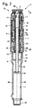
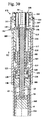
図1に示した噴射器1はハウジング2を有し、ハウジング2は、末端の上部ハウジング部分3と、上部ハウジング部分3の基端側に配置されるホールダ4とを含んでいる。ホールダ4はその基端に雄ねじ29を有し、該雄ねじには、図1では概略を示した噴射ニードル81をねじ止めすることができる。ホールダ4内には、図2に示した、噴射液を備える容器用の受容部5が形成されている。噴射液を備えた容器は第1実施形態を示す図には示していない。図1が示すように、ホールダ4は少なくとも1つの繰り抜き部10を有し、該繰り抜き部を通じて、噴射液を備えた容器を視認することができる。これにより、操作者は容器内にまだ噴射液があるかどうかを簡単に検知することができる。図2が示すように、互いに対向しあっている2つの繰り抜き部10がホールダ4に設けられている。
The
図1が示すように、ハウジング部分3の末端には操作要素6が配置され、該操作要素は、位置調整スリーブ7と、該位置調整スリーブ7の末端側に配置されている操作ボタン8とを有する。ハウジング部分3は、位置調整スリーブ7に隣接するように位置する視認窓9を有し、該視認窓を通じて、配量機構16に装着されたスケールを視認することができる。配量機構16はハウジング部分3内に配置されている。図1ではスケールは「0」を示しており、量調節が行われなかったことを操作者に知らせている。配量機構16は、配量調節が行われなかったゼロ位置85にある。
As shown in FIG. 1, an operating element 6 is disposed at the end of the
図2は、噴射器1の構成を詳細に示している。噴射器1は駆動体13を有し、駆動体は、実質的にスリーブ状に形成され、軸線方向において操作要素6の操作ボタン8と固定結合されている。なお、「軸線方向」という概念は、噴射器1の長手中心軸線50の方向に関わるものである。操作ボタン8は駆動体13とスナップ結合部を介して結合され、該スナップ結合部は駆動体13に対する操作ボタン8の回転を許容する。駆動体13は連結部14を介して操作要素6の位置調整スリーブ7と結合されている。図2に示した、操作ボタン8の第1の末端位置71では、連結部14は閉じている。操作要素6の位置調整スリーブ7は駆動体13と相対回転不能に結合されている。位置調整スリーブ7は、位置調整部材またはスケールパイプとも呼ばれる配量機構16と固定結合されている。駆動体13は送り部分20と相対回転不能に結合され、該送り部分は第1のねじ山結合部25を介して配量ピストン22のピストン棒23と結合されている。ピストン棒23はその基端にピストンディスク24を担持し、該ピストンディスクは、噴射液を備えた容器の栓と接触するために用いられ、該ピストンディスクを介して噴射液が容器から押し出される。
FIG. 2 shows the configuration of the
ピストン棒23はピストン棒リング30内に相対回転不能に保持されている。ピストン棒リング30は軸線方向に変位可能に噴射器1内に配置されている。図2に示した位置では、容器が受容部5に挿着されていなければ、ピストン棒リング30は圧縮ばね31によってその末端位置へ押される。この位置では、ピストン棒リング30はハウジング部分3に対し回転可能である。容器が受容部5内に挿着され、ホールダ4が固定ねじ山11でハウジング部分3と結合されれば、容器はピストン棒リング30を末端方向へ押す。噴射器1は内側管17を有し、該内側管はハウジング2の一部であり、相対回転不能に且つ軸線方向にハウジング部分3と固定結合されている。ピストン棒リング30は、その末端に、内側管17の輪郭に整合した輪郭12を有している。ピストン棒リング30は、その末端位置において、前記輪郭を介して内側管12と相対回転不能に結合され、よってハウジング部分3とも相対回転不能に結合されている。これにより、受容部5に容器が挿着されている場合、ピストン棒23はハウジング部分3内で相対回転不能に保持されている。ピストン棒23とハウジング部分3との相対回転不能な結合により、送り部分20の回転は、末端方向での、すなわち図2の矢印75の方向での送り部分20の運動を生じさせる。送り部分20と内側管17との間には係止装置26が形成され、該係止装置は送り部分20の係止位置を定義している。送り部分20の、図2に示した位置では、送り部分20は内側管17に形成されているストッパー28に当接し、該ストッパーは軸線方向での送り部分20の位置を定義している。
The
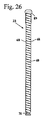
配量機構16は、第2のねじ山結合部18を介して内側管17と結合されている。内側管17は、ハウジング部分3と一体に形成されていてもよいが、これによって噴射器1の製造が非常に複雑になる。配量機構16は、該配量機構16の内部に突出しているスライダ19と相対回転不能に且つ軸線方向に変位可能に結合されている。スライダ19は第3のねじ山部分21を介して内側管17と結合されている。駆動体13と配量機構16との間では、操作ボタン8をその第1の位置71へ押す圧縮ばね15が作用する。配量機構16とハウジング3との間ではばね82が作用する。ばね82は有利にはねじりばねとして形成されている。本実施形態では、ばね82はコイル引張りばねであり、噴射配量を調整する際に伸びるとともに、噴射器1の長手中心軸線50のまわりにねじれる。
The
噴射液の押し出し量を調整するため、視認窓9内に所望の分量が現れるまで操作者は操作要素6を回転させる。その際位置調整スリーブ7が回転する。これによって、位置調整スリーブ7と相対回転不能に結合される配量機構16は、上部ハウジング部分3と内側管17とに対して回転する。配量機構16は、その回転運動により第2のねじ山結合部18を介して末端方向に、すなわち矢印75の方向に変位する。操作要素6と、該操作要素6の、軸線方向において操作ボタン8と固定結合されている駆動体13とは、配量機構16とともに運動する。操作要素6と駆動体13と配量機構16とは一緒に末端方向へ移動し、その際に第2のねじ山結合部18が設けられているために長手中心軸線50のまわりに回転する。
In order to adjust the push-out amount of the spray liquid, the operator rotates the operation element 6 until a desired amount appears in the viewing window 9. At that time, the
駆動体13と送り部分20との間の相対回転不能な結合を介して、送り部分20も上部ハウジング部分3に対し回転する。第1のねじ山結合部25を介して送り部分20も末端方向に移動する。スライダ19も、配量機構16と相対回転不能に結合されているので、末端方向に移動する。スライダ19および送り部分20も回転運動と長手方向の運動とを組み合わせた運動を実施し、その際スライダ19と送り部分20とが長手中心軸線50の方向へ変位する距離は、第1のねじ山結合部25または第3のねじ山結合部21を介して設定されている。スライダ19が第3のねじ山結合部を介して配量機構16と結合され、且つハウジング部分3と相対回転不能に結合されているように構成してもよい。
The
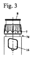
図3は、製造者によって設定されていない噴射液の分量を調整した後の噴射器1を示している。配量機構16は中間位置74にあり、この中間位置に関して以下でさらに詳細に説明する。
FIG. 3 shows the
図4および図5は、噴射液の所定押し出し量を調整した後の噴射器1を示している。送り部分20は末端方向に第1の調整距離aだけ移動している。噴射液の押し出し量を調整した後、送り部分20はストッパー28から第1の調整距離aだけ離間している。位置調整スリーブ7と操作ボタン8とを備えた操作要素6は、末端方向に第2の調整距離bだけ移動している。第2の調整距離bは、本実施形態の場合、位置調整スリーブ7の基端側端面とハウジング部分3の末端側端面との間で測定したものである。第2の調整距離aは第1の調整距離aよりも著しく大きい。本実施形態では、第2の調整距離bは第1の調整距離aの複数倍、例えばほぼ3倍である。調整距離aとbが異なっているのは、第1のねじ山結合部25と第2のねじ山結合部18都のピッチが異なっているためである。配量機構16も末端方向に第2の調整距離bだけ移動している。スライダ19は末端方向に第3の調整距離cだけ移動している。第3の調整距離cは第1の調整距離aと同じ大きさであってよい。しかしながら、第3の調整距離cは第1の調整距離aよりも大きいように構成してもよい。第3の調整距離cは、図5では、ねじ山を担持しているスライダ19の一部分の基端側端面(図2のこの端面の位置に比べて)に記入されている。ばね82は、噴射液押し出し量調整の際に緊張している。その際、ばね82は第2の調整距離bだけ伸びている。同時に、図8に示した、ばね82の端部83と84は、ハウジング2に対する配量機構16の回転のために長手中心軸線50のまわりに互いにねじれている。
FIG. 4 and FIG. 5 show the
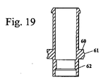
噴射液の最大調整量は、操作ボタン6と配量機構16とが末端方向に移動できる距離によって設定されている。この距離は、配量機構16とスライダ19との間に形成されたストッパー27(図5)によって制限される。図4が示すように、配量機構16は、その基端側端部に、内側へ向けられた段部41を有している。この段部41には、スライダ19に設けた係止エッジが軸線方向においてアンダーカット状に係合する。段部41は係止エッジ42とともにストッパー27を形成している。係止エッジ42が段部41に当接すると、噴射液の最大調整量が達成される。図1及び図2に示した状態での段部41と係止エッジ42との間の間隔は、第2の調整距離bから第1の調整距離aを差し引いたものに相当している。
The maximum adjustment amount of the spray liquid is set by the distance that the operation button 6 and the
図6が示すように、第1のハウジング部分3は、本実施形態では周回するように延在して形成されている係止凹部37を有している。係止凹部37内には、内側管17に形成されて半径方向外側へ突出するラッチ36が突出し、該ラッチは内側管17を噴射器1の長手中心軸線50の方向でハウジング部分3内で位置固定させる。内側管17は、その基端側端部でハウジング部分3の肩部76に当接している。内側管17は、回転位置を固定するために、半径方向外側へ突出しているピン48を有し、該ピンは視認窓9に隣接してハウジング部分3で係止される。
As shown in FIG. 6, the
図6は、圧縮ばね15の支持態様をも示している。圧縮ばね15はその基端側端部を配量機構16の肩部32で支持され、その末端側端部を駆動体13に形成されたエッジ39で支持されている。エッジ39は駆動体13のスリーブ状部分から外側へ突出している。エッジ39に隣接するように、該エッジ39の末端側には外歯38が駆動体13に配置されている。外歯38は位置調整スリーブ7に設けた内歯(図示せず)と協働し、これとともに連結部14を形成している。図6に示した、操作ボタン8の非操作位置では、連結部14は閉じており、駆動体13と位置調整スリーブ7との間の相対回転不能な結合を形成している。圧縮ばね15は駆動体13を連結部14の閉じ位置の方向に押す。これによって操作ボタン8はその末端側位置71へ押される。
FIG. 6 also shows how the
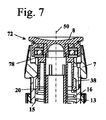
噴射すべき分量を調整した後、噴射を開始することができる。このため、操作ボタン8を図5の矢印77の方向に、すなわち基端部側方向へ押す。これによって操作ボタン8は圧縮ばね15の力に抗して長手中心軸線50の方向で位置調整スリーブ7内へ移動し、操作ボタン8は位置調整スリーブ7のストッパー78に当接する。図7は操作ボタン8をその基端側の第2の位置72で示している。この第2の位置では、駆動体13の外歯38は位置調整スリーブ7の領域から移動してしまっている。これにより、位置調整スリーブ7は駆動体13と操作ボタン8とに対して回転可能である。連結部14は開いている。操作ボタン8を図5で矢印77の方向へさらに押すと、配量機構16が内側管17内へ押し込まれ、その際基端側方向へ変位する。この場合、配量機構16は第2のねじ山結合部18が設けられているために回転する。配量機構16の回転のために、スライダ19も回転し、これによって基端側方向へ移動する。ハウジング3に対する配量機構16の回転は、ばね82によって支援される。スライダ19は連行段部62を有し、該連行段部は送り部分20の連行段部63に当接している。連行段部62と63を介して、スライダ19は、基端側方向へ移動するときに送り部分20を押し、これを同様に基端側方向へ移動させる。送り部分20は、回転しない操作ボタン8と軸線方向において固定結合されている駆動体13と相対回転不能に結合されている。送り部分20の回転は、分量の調整の際に係止位置へ調整された係止装置26によって阻止される。これにより、回転するスライダ19は送り部分20と一緒に回転することはできない。送り部分20は回転せず、配量ピストン22もピストン棒リング30を介してハウジング部分3と相対回転不能に結合されているので、送り部分20と配量ピストン22とは互いに固定結合されており、ともに基端側方向に移動し、その結果送り部分20はストッパー28に当接し、調整された噴射液の量が容器から完全に押し出される。
After adjusting the amount to be injected, the injection can be started. For this reason, the
噴射器1は、所定分量の噴射液を噴射するために設けられている。配量機構16は図4に示した少なくとも1つの噴射位置73を有し、この噴射位置で構造的に設定された所定量の噴射液が調整される。噴射位置73で係止装置26は係止されている。
The
配量機構16は、図3に示した少なくとも1つの中間位置74へもたらすこともできる。配量機構16の中間位置74では、非所定量の噴射液が調整される。配量機構16の中間位置74では係止装置26は係止されていない。非所定分量の噴射液が調整されていると、操作者が位置調整スリーブ7を離したときに配量機構16はばね82によって次の低い噴射位置73へ、またはゼロ位置85へ復帰される。
The
図6が示すように、ハウジング2の内側管17は、互いに固定結合されている基端側部分46と末端側部分47とから構成されている。内側管17は一体に製造されてもよい。しかしながら、これによって内側管17の製造は著しく複雑になる。製造をさらに容易にするために、内側管17を2つ以上の個別部材から形成するのが有利な場合がある。図8が示すように、ばね82は内側管17の末端側部分46と配量機構16との間にある。この場合、ばね82の第1の端部83は配量機構16に固定され、第2の端部84は内側管17の基端側部分46に固定されている。その際、端部83と84は有利には配量機構16および基端側部分46の適当な繰り抜き部に掛止されている。
As shown in FIG. 6, the
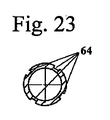
図9ないし図27は噴射器1の構成部材の詳細図である。図9ないし図11には駆動体13が示されている。駆動体13は、操作ボタン8との結合のために、その末端側端部に内側の係止用隆起部35を有し、該係止用隆起部は、操作ボタン8の接続部材に形成された係止エッジ34(図6に図示)にアンダーカット状に係合し、これによって操作ボタン8を軸線方向において駆動体13と結合させる。スリーブ状の駆動体13は、その内周に、本実施形態では4つの、軸線方向に延在する案内細条部40を有している。案内細条部40は、図23に示した送り部分20の縦溝64に整合し、これに係合している。案内細条部40は、縦溝64とともに、駆動体13と送り部分20との間の相対回転不能な結合部を形成している。案内細条部40は噴射器1の長手中心軸線50の方向で縦溝64内を自由に変位可能である。
9 to 27 are detailed views of components of the
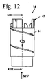
図12ないし図14は、スケールパイプまたは調整部材とも呼ばれる配量機構16を示している。配量機構16はスリーブ状に形成され、その外周に雄ねじ44を有している。雄ねじ44は、配量機構16の外周にらせん状に延在する溝として形成されている。配量機構16は、その末端側端部に、位置調整スリーブ7との相対回転不能結合部を形成しているフック状要素と傾斜要素とから形成される結合輪郭部43を担持している。図13と図14が示すように、配量機構16は、その基端側端部に、長手中心軸線50に対し平行に延在している2つの案内溝45を有している。案内溝45は互いに対向しあって配置され、スライダ19の縦細条部59(図19と図21に図示)と協働する。案内溝45内で案内されている縦細条部59は、配量機構16とスライダ19との間の相対回転不能な結合部を生じさせる。縦細条部59は長手中心軸線50の方向に自由に可動であり、その結果スライダ19は配量機構16に対し長手中心軸線50の方向に変位可能である。
FIGS. 12 to 14 show a
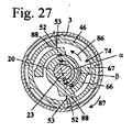
図15ないし図17には内側管17が示されている。内側管17は2つの部分から実施され、互いに固定結合されている基端側部分46と末端側部分47とからなる。内側管17の末端側部分47には、内周でらせん状に延在する細条部から形成されている雌ねじ49が配置されている。雌ねじ49はただ1つのねじ山によって形成されている。雌ねじ49を1つのねじ山の1つの部分または複数の部分だけで形成することも可能である。雌ねじ49は配量機構16の雄ねじ44と協働して、配量機構16の回転の際に該配量機構16を軸線方向へ変位させる。内側管17の基端側部分46には雌ねじ51が形成され、該雌ねじ51は、図18に示したスライダ19の雄ねじ61と協働する。雌ねじ51は雄ねじ61とともに第3のねじ山結合部21を形成している。雌ねじ51の基端側には縦細条部52が接続している。図27が示すように、本実施形態では特に2つの縦細条部52が設けられ、これらの縦細条部はほぼ互いに対向して配置されている。縦細条部52は、送り部分20の、互いに対向しあっているノッチ67とともに、係止装置の係止位置を定義しており、よって噴射位置73を定義している。本実施形態では、両噴射位置73は180゜の角度間隔αを有している。角度間隔αは有利には少なくともほぼ30゜、特に少なくとも45゜、特に有利には少なくとも60゜である。縦細条部52は、周方向に、図27に示した角度間隔βを互いに有しており、この角度間隔βは、本実施形態ではほぼ180゜以下、例えばほぼ160゜ないし175゜である。角度間隔βは、配量機構16を2つの噴射位置73の間で、または1つの噴射位置73と1つのゼロ位置85との間で中間位置74へ設定できる角度範囲に対応している。有利には、この角度範囲では係止装置26は送り部分20へ力を作用させず、したがって配量機構16へ力を作用させない。他の数量の縦細条部52および/またはノッチ67も有利である。例えば4つの縦細条部52と2つのノッチ67とが設けられていてよく、これら縦細条部とノッチとは、複数の噴射位置73の間で90゜の角度間隔αが生じるように、配置されている。
The
本実施形態では、縦細条部52とノッチ67とは、操作要素6の、係止位置から、比較的少量の噴射液に割り当てられている位置への戻り回転が不可能であるように、構成されている。しかしながら、縦細条部52の形状とノッチ67との形状が、例えば周方向に対称な構成を有することで、操作要素6の戻り回転を許容するようにしてもよい。
In the present embodiment, the
図17が示すように、内側管17の基端側端部では、心合わせエッジ58が基端側方向へ突出している。心合わせエッジ58はハウジング部分3の基端側開口部の中へ突出し、ハウジング部分3内での内側管17の固定着座を保証している。内側管17の基端側には、さらに、保持用接続部材56が基端側方向へ突出し、その基端側端部には、半径方向内側へ突出する複数の係止エッジ57が一体に形成されている。これらの係止エッジ57はピストン棒リング30の係止エッジ79(図5に示した)と協働する。係止エッジ79は係止エッジ57とともにピストン棒リング30のための軸線方向位置固定部を成している。図5が示すように、第2の圧縮ばね31は、係止エッジ79が係止エッジ57に当接するまで、ピストン棒リング30をその基端側位置へ押す。この位置で、配量ピストン22を末端側方向へ移動させるために、操作者はハウジング部分3をピストン棒リング30に対し回転させる。この構成は、噴射液用容器の交換の際のためのものである。
As shown in FIG. 17, the centering
図18ないし図20には、スライダ19が詳細に示されている。スライダ19はその末端側端部に係止エッジ42を有している。図18と図19が示すように、雄ねじ61は、半径方向外側へ突出している環状細条部60に形成されている。スライダ19も実質的にスリーブ状に形成されている。
18 to 20 show the
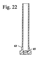
図21ないし図24は送り部分20を示している。送り部分20は、その基端側端部に、図24に示している2つの係止アーム66を有している。これらの係止アーム66はそれぞれ、その自由端に、半径方向外側へ向いているノッチ67を有している。係止アーム66はほぼ周方向に延在し、半径方向外側へ弾性的に形成されている。図22は、送り部分20の基端側端部に形成された雌ねじ65を示し、該雌ねじは配量ピストン22と協働する。雌ねじ65と係止アーム65とは送り部分20の同じ縦部分に配置されている。
21 to 24 show the feeding
図25と図26が示すように、ピストン棒23は雄ねじ69を有し、該雄ねじ69は送り部分20の雌ねじ65と協働し、これとともに第1のねじ山結合部25を形成している。ピストン棒23は、反対側の長手側に複数の平坦部68を有し、これら平坦部68は、図5に示したピストン棒リング30の開口部80の対応する平坦部と協働して、ピストン棒23の回転位置を固定する。ピストン棒23はその基端側端部に固定溝70を有し、該固定溝でピストンディスク24が保持されている。ピストン棒23はその末端側端部にストッパー89を有している。雄ねじ69はピストン棒23の末端側端部に終端を有し、そこでの輪郭は、本実施形態では、該雄ねじ69の外径よりも大きな直径を備えた円形の横断面を有している。この輪郭の基端側の面は、送り部分20の雌ねじ68に対するストッパー89を形成している。ピストン棒23は、ストッパー89において本実施形態では円形の横断面を有し、その外径はほぼピストン棒23の最大外径に相当している。これにより、ストッパー89は送り部分20の雌ねじ65にねじ込むことができない。しかしながら、雌ねじ65へのねじ込みを阻止するストッパー89の他の構成も有利である。ストッパー89は次のように配置されており、すなわちまだ容器内にある噴射液の量が調整されたときにストッパー89が送り部分20で係止されるように、配置されている。これにより操作者は、容器内にまだある噴射液の量よりも多い分量を調整することができない。
As shown in FIGS. 25 and 26, the
図27は、操作要素6と配量機構16と送り部分20とが中間位置74にあるときの送り部分20の配置構成を示している。ノッチ67は縦細条部52に対し間隔を持っている。ばね82(図8)は、配量機構16のゼロ位置85の方向で配量機構16に作用する。噴射分量を調整する際に閉じている連結部14と駆動体13とを介して、ばね82は送り部分20へも作用する。送り部分20は、図27に示した矢印86の方向において、ノッチ67の先行する係止位置の方向へ荷重される。例えば操作ボタン8を押して分量を注入するために操作者が位置調整スリーブ7を解放すると、配量機構16と送り部分20とは、ばね82の力のために、次に小さな所定の噴射液分量に割り当てられているか、或いは、噴射液の分量に割り当てられていない所定の先行位置まで戻る。その際、送り部分20は矢印86の方向に回転する。所定位置とは噴射位置73またはゼロ位置85である。所定量の噴射液を調整できないので、非所定量の噴射液の押し出しは阻止されている。
FIG. 27 shows an arrangement configuration of the feeding
操作要素6を、よって送り部分20をもさらに回転させると、ノッチ67は、該ノッチ67とともに係止装置26を形成している縦細条部52に打ち勝った後に、回転方向87において縦細条部52の後方へ到達する。回転方向87とは、噴射液の分量を調整する際に送り部分20と配量機構16とが回転する回転方向である。縦細条部は、矢印86の方向で前方にある側で係止要素53を形成しており、該係止要素53でノッチ67が係止される。ノッチ67が縦細条部52の係止要素53に当接すると、係止装置26が係止され、装置は所定の噴射位置73にある。ばね82の力による、矢印86の方向での送り部分20の更なる自律的運動は、ノッチ67が係止要素53に当接していることによって回避されている。操作者は操作ボタン8を押すことができ、調整した分量を噴射させることができる。調整した噴射液量の押し出しは、ばね82によって支援される。この場合、ノッチ67は縦細条部52において噴射器1の長手中心軸線50に対し平行に案内される。縦細条部52は、ある分量を噴射する際に送り部分20が長手中心軸線50のまわりに回転せず、これにより噴射液押し出し量が減少することを保証している。
When the operating element 6, and thus also the
縦細条部52は、回転方向87において前方にある側に、それぞれ1つの傾斜部88を有している。傾斜部88はノッチ67を半径方向内側へ偏向させ、したがって縦細条部52が乗り越えるのを容易にする。傾斜部88はノッチ67に対して、よって送り部分20と配量機構16とに対して、回転方向87とは逆の方向の力を作用させる。ノッチ67が傾斜部に当接している、配量機構16の位置で、送り部分20は、係止装置26によって及ぼされる回転方向87とは逆の方向の力のために復帰して、操作者が逆方向の力を送り部分20に対し及ぼさなければ、ノッチ67はもはや傾斜部に当接しない。縦細条部52間の角度間隔βで、ノッチ67は内側管17の基端側部分46に対し間隔を有し、該基端側部分46と接触していない。有利には、基端側部分46の内周はこの領域で長手中心軸線50のまわりに円弧で延在している。この領域では、係止装置26は送り部分20または配量機構16に対して宝を作用させない。送り部分20および配量機構16の、噴射位置73またはゼロ位置85への復帰は、この領域ではもっぱらばね82の力だけで行われる。本実施形態では、ただ1つの所定噴射液量のみを容器から押し出すことができるような噴射器1が示されている。この量は、操作要素が180゜回転した時に達成される。しかしながら、異なる噴射液量が割り当てられている複数の噴射位置73が可能であるように構成してもよい。
Each
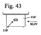
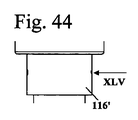
図29ないし図70は、噴射器101の1実施形態を示している。噴射器101はハウジング102を有し、該ハウジングは上部ハウジング部分103を備え、該上部ハウジング部分にホールダ4が固定されている。なお、前図の場合と同じ参照符号は同じ構成要素を表している。上部ハウジング部分103の末端側端部には操作要素106が配置され、該操作要素は位置調整スリーブ107と操作ボタン108とを含んでいる。図29には、噴射器101がそのゼロ位置185で示されている。上部ハウジング部分103は視認窓109を有し、該視認窓を通じてスケール110を見ることができる。本実施形態では、ゼロ位置185でスケールは「0」を示す。操作ボタン108は図29ではその末端側位置171にある。
29 to 70 show an embodiment of the
図30は、噴射器101の構成を詳細に示している。図30はホールダ4に挿着されている容器104も示しており、該容器の栓105には配量ピストン22のピストンディスク24が当接している。噴射器101はピストン棒リング130を有し、該ピストン棒リング内でピストン棒23が相対回転不能に案内されている。ピストン棒リング130を介してピストン棒23はハウジング102に対し相対回転不能に保持されている。ピストン棒23はピストン棒リング130の開口部180を通じて突出している。図示した噴射器101は次のような実施形態で示されており、すなわち使用者がすでに容器を取り付けた噴射器を入手し、容器104が空になれば、使用者が噴射器101を容器104とともに廃棄するような実施形態で示している。容器104の交換は行われない。ホールダ4は上部ハウジング部分103と固定結合され、例えばこれと着脱不能にスナップ結合または接着されている。ピストン棒リング130はホールダ4によって上部ハウジング部分103内で軸線方向に、すなわち長手中心軸線50の方向に位置固定されている。ピストン棒リング130は、さらに以下で詳細に説明するようにハウジング103内で相対回転不能に保持されている。
FIG. 30 shows the configuration of the
噴射器101は、第1のねじ山結合部125を介してピストン棒23と結合されている送り部分120を有している。送り部分120の基端側端部には係止装置126が配置されている。係止装置126はピストン棒リング130と送り部分120との間に形成されている。送り部分120は駆動体113と相対回転不能に結合されている。駆動体113は操作ボタン108と相対回転不能に結合されている。本実施形態では、駆動体113は操作ボタン108で受容され、すなわち操作ボタン108と一体に形成されている。
The
送り部分120には、基端側方向で送り部分120に作用するスライダ119が当接している。スライダ119は、第2のねじ山結合部121を介して上部ハウジング部分103と結合されている。第2のねじ山結合部121は上部ハウジング部分103のエッジ122に形成され、該エッジは内側へ突出している。スライダ119は配量機構116と相対回転不能に結合されている。配量機構116は位置調整スリーブ107と一体に形成され、これとともに位置調整部分112を形成している。しかし、位置調整部分112は軸線方向には位置固定であるようにハウジング102内に相対回転不能に支持されている。このため、位置調整部分112は、配量機構116に、半径方向外側へ突出するエッジ117を有し、該エッジは、以下に詳細に説明するようにハウジング2で係止される。エッジ117はその基端側端部に、組み立てを容易にするための傾斜部118を有している。配量機構116にはスケール110(図29)が取り付けられている。噴射液の押し出し量を調整する際、位置調整スリーブ107は1回転以下だけ回転することができ、その結果スケール110のどの値にも1つの一義的な噴射液量が割り当てられている。本実施形態では、位置調整スリーブ107は半回転だけ回転可能である。
A
位置調整スリーブ107は、その末端側端部において開口している。位置調整スリーブ107内では、操作ボタン108が軸線方向に変位可能に保持されている。操作ボタン108は、位置調整スリーブ107内へ突出しているエッジ123を有している。エッジ123と位置調整スリーブ107との間には連結部114が形成されている。操作ボタン108の、図29および図30に示した末端側位置171では、連結部114は閉じており、操作ボタン108を位置調整スリーブ107と相対回転不能に結合させている。操作ボタン108は、半径方向において駆動体113とエッジ123との間に配置されている筒状接続部材111を有している。この接続部材111の端面はストッパー178を形成し、該ストッパー178は、位置調整部分112の方部132と協働して、これとともに操作ボタン108の基端側位置を決定している。接続部材111の外面には、操作ボタン108をその末端側位置171へあらかじめ付勢している圧縮ばね115が配置されている。
The
図31と図32は、最大分量を調整した後の噴射器101を示している。視認窓109ではスケール110が数字「4」を表示している。この位置では、噴射器101は噴射位置173にあり、該噴射位置では所定量の噴射液が調整されている。図32が示すように、連結部114は依然閉じている。操作ボタン108はその末端側位置171にある。噴射液の押し出し量を調整するため、位置調整スリーブ107を、図29および図30に示した位置から半回転だけ時計方向にハウジング102に対し回転させる。その際、駆動体113は送り部分120を回転させる。第1のねじ山部分125が設けられているために、送り部分120は末端側方向へ移動し、すなわち第1の調整距離dだけ移動する。配量機構116はスライダ119を連行して回転させる。スライダ119は第2のねじ山部分121を介して第2の調整距離eだけ移動し、この第2の調整距離は、有利には少なくとも第1の調整距離dに相当している。位置調整スリーブ107が回転すると、送り部分120はハウジング部分103に対し回転し、これによって係止装置126は感知できて聞くことのできるクリックを生じさせる。
31 and 32 show the
調整した噴射液量を押し出すためには、操作ボタン108を矢印77の方向で基端側へ移動させねばならない。操作ボタン108の基端側位置172は図33に示されている。この位置では連結部114は解除されている。操作ボタン108は、連結部114の一部分である外歯138を有している。操作ボタン108の外歯138は、操作ボタン108が基端側方向へ移動するときに、位置調整スリーブ107の対向歯部の領域から出る。これによって位置調整スリーブ107は操作ボタン108に対し回転可能である。連結部114は解除されている。操作ボタン108は、ストッパー178が配量機構116の肩部132に当接するまで、位置調整スリーブ107内へ押し込むことができる。ストッパー178は次のように構成されており、すなわち配量機構116と操作ボタン108との間の摩擦が小さいように、構成されている。このため、本実施形態では、接続部材111は丸い輪郭を有している。
In order to push out the adjusted amount of the spray liquid, the
図34ないし図36が示しているように、配量機構116とハウジングに固定して保持されているピストン棒リング130との間に、ねじりばねとして形成されているばね182が形成されている。ばね182は、図34ないし図36に示したゼロ位置で、有利にはすでにあらかじめ緊張せしめられている。これによって、ばね182が最後まで噴射を持続させるよう保証され、すなわち栓105が容器104内で所望の終端位置へ変位できるよう保証される。位置調整スリーブ107がピストン棒リング130に対して時計方向に回転すると、ばね182はさらに緊張せしめられる。係止装置126は、各ノッチを乗り越えた後に、ゼロ位置185への位置調整スリーブ107の戻し回転を阻止する。所望の分量が調整されると、操作ボタン108を押す。これによって連結部114が解除され、位置調整スリーブ107はばね182によってそのゼロ位置185へ戻し回転せしめられる。配量機構116を備えた位置調整部分112の回転運動により、スライダ119はハウジング部分103に対して回転し、したがって第2のねじ山結合部121を介してスライダ119は軸線方向へ、基端側へ移動し、すなわち調整距離eだけ移動する。図32が示すように、スライダ119は連行段部162を有し、該連行段部は、送り部分120の連行段部163と協働して、送り部分120を基端側方向へ連行する。その際、スライダ119は送り部分120を第1の調整距離dだけ変位させる。この場合、送り部分120は係止装置126を介して周方向において支持され、その結果送り部分120は回転することができない。ピストン棒23がピストンガイド130で相対回転不能に保持されているので、ピストン棒23は基端側方向へ移動して、栓105を介して、調整された噴射液量を容器104から押し出す。
As shown in FIGS. 34 to 36, a
図34ないし図36が示すように、ばね182の第1の端部183は配量機構116のエッジ117に掛止されている。ばね182の第2の端部184はピストン棒リング130で保持されている。これらの図が示すように、ピストン棒リング130は2つのアーム133,134を有し、これらのアームは、ピストン棒リング130の反対側で、軸線方向末端側へ延在している。第1のアーム133はスリット137を有し、該スリット内でばね182の第2の端部184が案内されている。ばね182の第2の端部184は、ピストン棒リング130を介してハウジング102と相対回転不能に結合されている。分量を調整する際、ばね182は緊張せしめられる。というのは、第1の端部183がハウジングに固定して保持されている第2の端部184に対して回転するからである。分量を調整した後、装置は係止装置126を介して、使用者が操作ボタン108を押すことで連結部114を解除するまで、噴射位置173で保持される。連結部114を解除した後、ばね182は位置調整部分112をゼロ位置185へ戻し回転させる。これによってスライダ119もゼロ位置185へ戻り、その際に送り部分120を、よってピストン棒23を基端側方向へ変位させ、その結果調整された噴射液量が容器104から押し出される。
As shown in FIGS. 34 to 36, the
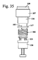
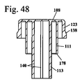
図37ないし図42は、位置調整部分112の構成を詳細に示している。位置調整部分112は実質的に筒状に形成され、そして位置調整スリーブ7を形成する、外径を拡大した部分と、これに接続し、外径を縮小した、配量機構116を形成する領域とを有している。エッジ117には接続部材143が接続し、該接続部材は、スライダ119との相対回転不能な結合のための案内溝145を有している。本実施形態では、互いに対向しあっている2つの案内溝145が設けられている。しかし、他の数量の案内溝145も有利である。図34が示すように、接続部材143の外周ではばね182が案内されている。図40が示すように、エッジ117は開口部144を有し、該開口部にばね182の第1の端部183が掛止されている。
37 to 42 show the configuration of the
図39が示すように、位置調整スリーブ107の内面にはただ1つの係止歯146が配置され、該係止歯は操作ボタン108の外歯138と協働する。しかし、より多い数量の係止歯146が設けられていてもよい。ただ1つの係止歯146が設けられていることにより、操作ボタン108を、軸線方向に押し込んで係止することによって、係止歯146の後方に位置するように簡単に位置調整スリーブ107内に取り付けることができる。図46が示すように、操作ボタン108は、外歯138の末端側に、係止歯146の後方で係止されるエッジ139を有している。これにより、操作ボタン108は軸線方向において位置調整スリーブ107内に位置固定される。
As shown in FIG. 39, only one
図38、図41、図42はスケール110を示している。スケール110は、「0」を表すゼロ位置185と、「1」、「2」、「3」、「4」を表す4つの噴射位置173とを表示している。これら噴射位置173は互いに等間隔で配置されている。
38, 41, and 42 show the
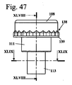
図43ないし図45は、配量機構116’の一部分を示している。配量機構116’はスケール110’を有し、該スケールは、「0」を表すゼロ位置185と、「1」で表されているただ1つの噴射位置173とを備えている。配量機構116’を備えた噴射器101では、構造的に設定されるただ1つの噴射液押し出し量のみを調整することができる。
43 to 45 show a part of the dispensing mechanism 116 '. The
図46ないし図49が示すように、駆動体113は、その内面に、送り部分120との相対回転不能な結合のために用いる案内細条部140を有している。本実施形態では、内周に均等に配分されている4つの案内細条部140が設けられている。特に図48が示しているように、エッジ123は軸線方向において接続部材111よりも短く、接続部材111の内部に配置されている駆動体113は、接続部材111よりも長い。
As shown in FIGS. 46 to 49, the driving
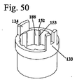
図50ないし図53はピストン棒リング130を示している。ピストン棒リング130は段部147を有し、該段部には組み立て状態でホールダ4が当接し、ピストン棒リング130をハウジング102内で軸線方向に固定している。図50と図53が示すように、ピストン棒リング130は、その内周に、複数の縦細条部152によって形成されている歯部を有している。縦細条部152は、それぞれ片側に係止要素153を有し、反対側に傾斜部188を有している。縦細条部152は非対称に形成されている。係止要素153は長手中心軸線50に対しほぼ半径方向に向けられている。これにより、調整された噴射位置から次に低い噴射位置への戻り回転は不可能である。しかしながら係止要素153を、戻り回転が可能であるように構成してもよい。係止要素153は次のように構成すべきであり、すなわちばね182によってもたらされる回転モーメントだけで係止要素153を乗り越えることができないように、構成すべきである。本実施形態では、8つの係止要素153がピストン棒リング130の内周に均等に配分して設けられている。所望の噴射液設定料を調整できるように、他の数量の係止要素153も有利である。
50 to 53 show the
複数の縦細条部152の間には、それぞれ、ピストン棒リング130の内壁が長手中心軸線50のまわりに円弧状に延在している領域が配置されている。図53が示すように、ピストン棒リング130は、ピストン棒23を相対回転不能に結合させるための開口部180を有している。この相対回転不能な固定のため、開口部180は直線状に延在している側壁181を有している。図51と図52が示しているように、第2のアーム134は軸線方向において第1のアーム133よりも著しく短く形成されている。第1のアーム133にはストッパー135と136が形成され、これらのストッパーとスライダ119が協働する。第2のアーム134はスライダ119のストッパーの領域まで突出していない。
Between the plurality of
図54と図55は、ただ1つの分量しか調整できず、図43ないし図45の配量機構116‘を有することのできる噴射器101のためのピストン棒リング130’の構成を示している。図54と図55が示すように、2つの縦細条部152が互いに対向するように配置されている。縦細条部152には係止要素153と傾斜部188とが形成されている。唯一の噴射位置173では、それぞれの係止要素153に1つのノッチ167(図59)が係止される。
54 and 55 show the configuration of the piston rod ring 130 'for the
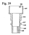
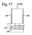
図56ないし図58はスライダ119を詳細に示している。スライダ119は筒状部分148を有し、該筒状部分は、その外面に、配量機構116は案内溝145の中へ突出している縦細条部159を有している。これによってスライダ119は配量機構116と相対回転不能に結合されている。スライダ119は、その末端側に、雄ねじ161を有する環状細条部160を有している。雄ねじ161は、図65に示した、上部ハウジング部分103の雌ねじ151とともに、第2のねじ山結合部121を形成している。環状細条部160と縦細条部159を担持している筒状部分148との間には、半径方向外側へ突出している2つのアーム129と131が配置されている。第1のアーム129には第1のストッパー127が形成され、該第1のストッパーは、ピストン棒リング130の第1のアーム133の第1のストッパー135と協働して、これとともに噴射器101のゼロ位置を定義している。第2のアーム131は第2のストッパー128を有し、該第2のストッパーは、ピストン棒リング130の第2のストッパー136とともに最大分量を定義し、すなわち最大に調整される噴射液押し出し量を定義している。ゼロ位置と最大分量との間でスライダ119はピストン棒リング130に対し、本実施形態では半回転だけ回転可能である。他の回転範囲も有利である。
56 to 58 show the
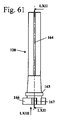
図59ないし図63は送り部分120の詳細を示している。送り部分120はスリーブ状部分を有し、該スリーブ状部分はその外面に縦溝164を有している。本実施形態では、4つの縦溝164が設けられている。縦溝164内には操作ボタン108の案内細条部140が突出している。これによって操作ボタン108と送り部分120とは互いに相対回転不能に結合されている。送り部分120は、その末端側に、自由端面にそれぞれ1つのノッチ167を担持している2つの係止アーム166を有している。送り部分120はさらにその基端側端部に雌ねじ165を有し、該雌ねじにピストン棒23がねじ止めされてこれとともに第2のねじ山結合部121を形成している。図61と図62には連行段部163も示されており、該連行段部にスライダ119の連行段部162が当接している。
59 to 63 show details of the feeding
図64ないし図66は上部ハウジング部分103を示している。上部ハウジング部分103はスリーブ状に形成され、その末端側端部に隣接して視認窓109を有している。内側へ突出しているエッジ122は、雌ねじ151を有している。上部ハウジング部分103はその内面に係止用隆起部142を有し、該係止用隆起部の背後で位置調整部分のエッジ(図37ないし図40)のエッジ117が係止される。
FIGS. 64 to 66 show the
図66が示すように、エッジ122は、互いに対向しあうように配置されている2つの開口部141を有している。これら開口部141を通じてピストン棒リング130のアーム133と134(図50)が突出する。これによってピストン棒リング130はハウジング102内で相対回転不能に保持されている。
As shown in FIG. 66, the
図67は噴射器101を中間位置174で示したもので、該中間位置では、非所定噴射液量が調整されている。視認窓109内では、スケール110の数字「3」の一部が見える。図68が示すように、この位置ではノッチ167は傾斜部188に隣接している。ノッチ167は係止要素153に係止されていない。ばね182はこの位置で送り部分120に対し矢印186の方向で力を及ぼし、ノッチ167が係止要素153に当接するまで送り部分120を回転させる。複数の係止要素153は周方向において長手中心軸線50のまわりに角度γだけ互いに間隔をもって位置し、この角度はほぼ45゜である。隣接している縦細条部152はたがいに角度間隔δを有し、この角度間隔は例えばほぼ20゜ないしほぼ40゜である。角度間隔δは、配量機構116が2つの噴射位置173の間で調整できる角度範囲、または、中間位置174で噴射位置173とゼロ位置185との間で調整できる角度範囲に相当している。中間位置174は図68に示されている。中間位置174では、操作者が位置調整スリーブ107を離して、次に低い噴射位置173またはゼロ位置185に達したときに、ねじりばね182は送り部分120を矢印186の方向に移動させる。送り部分120を噴射位置173に調整するため、操作者は送り部分120を矢印187の方向にもさらに回転させて、図69および図70に示した噴射位置173に達するようにすることができる。この位置ではノッチ167は係止要素153の後方に当接し、ばね力(図68の矢印186)に抗して保持されている。送り部分120は、調整した噴射液量を押し出したときにノッチ167でもって縦細条部152で軸線方向に案内される。
FIG. 67 shows the
噴射器101は、容器104の交換が不可能な1回限りの使い捨て噴射器として示されている。しかしながら、ピストン棒リング130の代わりに、軸線方向に上部ハウジング部分で保持されて容器104の交換を可能にするピストン棒リング30も使用することができる。
The
配量機構は、噴射分量を調整するため、噴射器の長手中心軸線のまわりに回転可能である。これによってコンパクトな構成と簡単な操作とが得られる。The dispensing mechanism is rotatable about the longitudinal central axis of the injector to adjust the injection quantity. This provides a compact configuration and simple operation.
係止装置は送り部分とハウジングとの間で作用する。この場合送り部分は、噴射分量を調整するため、噴射器の長手中心軸線のまわりに回転可能である。送り部分は、噴射分量の調整の際に配量機構と相対回転不能に結合されている。分量を押し出す際、送り部分は長手中心軸線の方向でハウジングに対し移動する。これにより、噴射液を押し出す際に係止装置は作用せず、係止ステップは操作者に聞き取れず、または感知できないことが達成される。さらに係止装置は次のように構成されていてよく、すなわち噴射位置へ到達した後に送り部分が次に低い噴射位置へ戻り回転することが不可能であるように、構成されていてよい。送り部分がハウジングの少なくとも1つの縦細条部で案内されていることにより、簡潔な構成が得られる。縦細条部に係止装置の少なくとも1つの係止要素が形成されている。これによって簡潔な構成が得られる。縦細条部は、同時に、係止要素と送り部分のための縦案内部とを形成している。The locking device acts between the feed part and the housing. In this case, the feed portion is rotatable around the longitudinal central axis of the injector in order to adjust the injection quantity. The feed portion is coupled to the metering mechanism so as not to rotate relative to the amount of injection. When extruding the quantity, the feed part moves relative to the housing in the direction of the longitudinal central axis. Thereby, it is achieved that the locking device does not act when pushing out the spray liquid, and the locking step cannot be heard or sensed by the operator. Furthermore, the locking device may be configured as follows, i.e., so that after reaching the injection position, the feed part cannot be rotated back to the next lower injection position. A simple construction is obtained because the feed part is guided by at least one longitudinal strip of the housing. At least one locking element of the locking device is formed on the longitudinal strip. This provides a simple configuration. The longitudinal strips simultaneously form a locking element and a longitudinal guide for the feed part.
有利には、ばねは、噴射分量の調整の際に緊張せしめられる。この場合、ばねは配量機構のゼロ位置ですでにあらかじめ緊張せしめられていてよい。しかしながら、ばねが配量機構のゼロ位置で十分に弛緩しているようにしてもよい。ばねは、特に配量機構とハウジングとの間で作用する。有利には、ばねは配量機構およびハウジングとダイレクトに結合されている。これによって好ましい組み付け状況が生じる。特に有利には、ばねはコイルばねであり、ばねの第1の端部は配量機構に掛止され、ばねの第2の端部はハウジングに掛止されている。しかしながら、ばねの一端がハウジング内に相対回転不能に保持されている構成部材に固定されているようにしてもよい。これによって噴射器の個々の部分の簡潔な構成が生じる。Advantageously, the spring is tensioned during the adjustment of the injection quantity. In this case, the spring may already be pre-tensioned at the zero position of the dispensing mechanism. However, the spring may be sufficiently relaxed at the zero position of the dispensing mechanism. The spring acts in particular between the metering mechanism and the housing. Advantageously, the spring is directly coupled to the metering mechanism and the housing. This creates a favorable assembly situation. Particularly advantageously, the spring is a coil spring, the first end of the spring being hooked to the metering mechanism and the second end of the spring being hooked to the housing. However, one end of the spring may be fixed to a constituent member that is held in the housing so as not to be relatively rotatable. This results in a simple construction of the individual parts of the injector.
係止装置は、有利には、噴射位置に達したときに、操作者に聞こえるような、および/または、操作者が感知できるような報知を与える。有利には、係止装置は、配量機構の中間位置で該配量機構に対し力を及ぼさない。これにより、噴射位置への配量機構の復帰は、係止装置によって及ぼされる力に抗して行われない。これにより、ばねによって及ぼされる復帰力に係止装置によって及ぼされる力が重畳されないので、簡単で確実な復帰が達成される。さらに、係止装置が配量機構の中間位置で該配量機構に対し力を及ぼさないことにより、使用できる構成空間が狭くても所定数の係止位置を達成できる。係止装置が、係止要素と協働する少なくとも1つのノッチを有していれば、簡潔な構成が得られる。The locking device advantageously provides a notification that can be heard by the operator and / or perceived by the operator when the injection position is reached. Advantageously, the locking device does not exert a force on the dispensing mechanism at an intermediate position of the dispensing mechanism. Thereby, the return of the dispensing mechanism to the injection position is not carried out against the force exerted by the locking device. Thereby, since the force exerted by the locking device is not superimposed on the restoring force exerted by the spring, a simple and reliable return is achieved. Further, since the locking device does not exert a force on the dispensing mechanism at an intermediate position of the dispensing mechanism, a predetermined number of locking positions can be achieved even if the usable configuration space is narrow. A simple construction is obtained if the locking device has at least one notch cooperating with the locking element.
配量機構が回転可能である場合、少なくとも2つの噴射位置が設けられ、これら噴射位置は、長手中心軸線のまわりで周方向に互いに少なくともほぼ30゜の角度間隔を有している。角度間隔がほぼ30゜またはそれ以上の場合、係止装置の幾何学的構成だけでは、配量機構の所定位置への復帰を確実に保証することはできない。2つの噴射位置の間の角度間隔は有利には少なくともほぼ45゜、特に少なくともほぼ60゜である。この角度間隔は、有利には、該角度間隔の整数倍が360゜であるように選定されている。If the metering mechanism is rotatable, at least two injection positions are provided, the injection positions having an angular spacing of at least approximately 30 ° from one another in the circumferential direction about the longitudinal central axis. If the angular spacing is approximately 30 ° or more, the geometry of the locking device alone cannot reliably guarantee the return of the dispensing mechanism to a predetermined position. The angular spacing between the two injection positions is preferably at least approximately 45 °, in particular at least approximately 60 °. This angular spacing is advantageously chosen such that an integral multiple of the angular spacing is 360 °.
Claims (16)
前記配量機構(16,116)が少なくとも1つの中間位置(74)に位置調整可能であり、該中間位置では所定噴射液分量が調整されていないこと、
前記配量機構(16,116)と前記ハウジング(2,102)との間にばね(82,182)が作用し、該ばねは、前記操作要素(6,106)が操作されていないときに前記配量機構(16,116)を前記中間位置(74)から1つの噴射位置(73,173)または前記ゼロ位置(85,185)へ復帰させることを特徴とする噴射器。 An injector provided with a housing (2,102), wherein a receiving part (5) for a container provided with an injection liquid is formed in the housing, and the injector (1,101) controls an injection amount. A dispensing mechanism (16) having an operating element (6, 106) for adjusting, wherein the injector (1, 101) moves relative to the housing (2, 102) when adjusting the injection amount. 116), and the dispensing mechanism (16, 116) has a zero position (85, 185) and at least one injection position (73, 173), wherein the zero position (85, 185) The amount is not adjusted, a predetermined amount of spray liquid is adjusted at each injection position (73, 173), and the injector (1, 101) moves relative to each other when adjusting the amount of injection. Has a locking device (26, 126) acting between the parts In the injector locking position of the locking device (26, 126) is assigned to each injection position of the metering mechanism (16, 116) (73,173)
The dispensing mechanism (16, 116) can be adjusted to at least one intermediate position (74), and a predetermined amount of the injected liquid is not adjusted at the intermediate position;
A spring (82, 182) acts between the dispensing mechanism (16, 116) and the housing (2, 102), and the spring is operated when the operating element (6, 106) is not operated. An injector characterized by returning the dispensing mechanism (16, 116) from the intermediate position (74) to one injection position (73, 173) or the zero position (85, 185).
Applications Claiming Priority (3)
| Application Number | Priority Date | Filing Date | Title |
|---|---|---|---|
| DE202013001350.8 | 2013-02-08 | ||
| DE201320001350 DE202013001350U1 (en) | 2013-02-08 | 2013-02-08 | injection device |
| PCT/EP2014/000313 WO2014121929A1 (en) | 2013-02-08 | 2014-02-05 | Injection device |
Publications (1)
| Publication Number | Publication Date |
|---|---|
| JP2016507302A true JP2016507302A (en) | 2016-03-10 |
Family
ID=50070502
Family Applications (1)
| Application Number | Title | Priority Date | Filing Date |
|---|---|---|---|
| JP2015556420A Pending JP2016507302A (en) | 2013-02-08 | 2014-02-05 | Injector |
Country Status (14)
| Country | Link |
|---|---|
| US (2) | US9694136B2 (en) |
| EP (2) | EP2953671B1 (en) |
| JP (1) | JP2016507302A (en) |
| CN (2) | CN105188811B (en) |
| BR (1) | BR112015018835A2 (en) |
| CA (1) | CA2900428C (en) |
| DE (1) | DE202013001350U1 (en) |
| DK (2) | DK2953671T3 (en) |
| ES (1) | ES2656466T3 (en) |
| HK (1) | HK1256336A1 (en) |
| NO (1) | NO3043972T3 (en) |
| PT (1) | PT2953671T (en) |
| RU (1) | RU2626143C2 (en) |
| WO (1) | WO2014121929A1 (en) |
Families Citing this family (18)
| Publication number | Priority date | Publication date | Assignee | Title |
|---|---|---|---|---|
| DE202013001350U1 (en) * | 2013-02-08 | 2014-05-09 | Haselmeier Gmbh | injection device |
| US10500345B2 (en) * | 2013-11-22 | 2019-12-10 | Sanofi-Aventis Deutschland Gmbh | Spring assisted drug delivery device |
| CN105764546B (en) | 2013-11-22 | 2020-07-17 | 赛诺菲-安万特德国有限公司 | Spring assisted drug delivery device |
| JP6711749B2 (en) * | 2013-11-22 | 2020-06-17 | サノフィ−アベンティス・ドイチュラント・ゲゼルシャフト・ミット・ベシュレンクテル・ハフツング | Drug delivery device with dose knob clutch |
| WO2016169946A1 (en) | 2015-04-23 | 2016-10-27 | Sanofi-Aventis Deutschland Gmbh | Drug delivery device and retaining member for a drug delivery device |
| DE202015006844U1 (en) * | 2015-09-30 | 2016-01-15 | Haselmeier Ag | injection device |
| DE202015006845U1 (en) | 2015-09-30 | 2016-01-15 | Haselmeier Ag | injection device |
| DE202015006842U1 (en) | 2015-09-30 | 2016-01-15 | Haselmeier Ag | injection device |
| DE202015006841U1 (en) | 2015-09-30 | 2016-01-15 | Haselmeier Ag | injection device |
| DE202015007351U1 (en) * | 2015-10-22 | 2017-01-27 | Haselmeier Ag | injection device |
| WO2018185317A1 (en) * | 2017-04-07 | 2018-10-11 | Novo Nordisk A/S | End-of-content mechanism |
| US10688247B2 (en) | 2017-07-13 | 2020-06-23 | Haselmeier Ag | Injection device with flexible dose selection |
| JP1631348S (en) | 2017-11-06 | 2019-05-13 | ||
| US20220096754A1 (en) * | 2019-01-24 | 2022-03-31 | Sanofi | Drug Delivery Device |
| CN113631208A (en) | 2019-04-11 | 2021-11-09 | 海斯迈股份公司 | Dose delivery mechanism in which twisting through is prevented |
| EP3520844A1 (en) * | 2019-05-07 | 2019-08-07 | Tecpharma Licensing AG | Dosing device for an injection device |
| BR112023020728A2 (en) * | 2021-04-07 | 2024-01-09 | Medmix Switzerland Ag | DRUG RELEASE DEVICE WITH BALANCING WEIGHT |
| EP4070832A1 (en) | 2021-04-07 | 2022-10-12 | medmix Switzerland AG | Keyed connectors |
Citations (2)
| Publication number | Priority date | Publication date | Assignee | Title |
|---|---|---|---|---|
| JP2007509662A (en) * | 2003-11-03 | 2007-04-19 | ハーゼルマイアー エス.アー.エル.エル. | Injection device |
| WO2011101349A1 (en) * | 2010-02-17 | 2011-08-25 | Sanofi-Aventis Deutschland Gmbh | Automatic injection device with torsional spring |
Family Cites Families (23)
| Publication number | Priority date | Publication date | Assignee | Title |
|---|---|---|---|---|
| DE60203118T2 (en) * | 2001-07-16 | 2006-04-13 | Eli Lilly And Co., Indianapolis | MEDICAMENT ADMINISTRATION DEVICE WITH ROTATION PRIMING AND BY PULL / MOVE EXECUTABLE INJECTION |
| GB0200444D0 (en) * | 2002-01-10 | 2002-02-27 | Owen Mumford Ltd | Improvements relating to medical injection devices |
| AT7347U1 (en) * | 2003-08-29 | 2005-02-25 | Pharma Consult Ges M B H & Co | DEVICE FOR THE AUTOMATIC INJECTION OF INJECTION LIQUIDS |
| DE102004004310A1 (en) * | 2004-01-28 | 2005-08-18 | Tecpharma Licensing Ag | Injection device with lockable dosing member |
| US7148825B2 (en) * | 2004-05-10 | 2006-12-12 | Broadcom Corporation | Data interface including gray coding |
| ZA200703707B (en) * | 2004-10-21 | 2009-02-25 | Novo Nordisk As | Dial-Down Mechanism for Wind-up Pen |
| AU2006207744B2 (en) * | 2005-01-21 | 2011-08-11 | Novo Nordisk A/S | An automatic injection device with a top release mechanism |
| US20060276753A1 (en) * | 2005-06-01 | 2006-12-07 | Victor Kronestedt | Device for delivering medicament |
| DE102005060929A1 (en) * | 2005-09-14 | 2007-03-15 | Tecpharma Licensing Ag | Product e.g. insulin, injecting device, has housing and operating knob with locking units that are formed such that movement of operating knob in one direction has smaller resistance in contrast to movement in other direction |
| CA2652396C (en) * | 2006-05-18 | 2014-07-08 | Novo Nordisk A/S | An injection device with mode locking means |
| US8348905B2 (en) * | 2008-01-23 | 2013-01-08 | Novo Nordisk A/S | Device for injecting apportioned doses of liquid drug |
| JP5558477B2 (en) | 2008-10-24 | 2014-07-23 | ノボ・ノルデイスク・エー/エス | Dial-down mechanism for roll-up pen |
| SE0900371A1 (en) | 2009-03-24 | 2010-09-25 | Istvan Bartha | Device for distribution of liquid drugs |
| US9579458B2 (en) * | 2009-04-03 | 2017-02-28 | Shl Group Ab | Medicament delivery device |
| EP2424597A1 (en) * | 2009-04-30 | 2012-03-07 | Sanofi-Aventis Deutschland GmbH | Axially adjustable connection of piston rod to piston for drive mechanism of a drug delivery device |
| EP2588163A4 (en) * | 2009-06-05 | 2017-12-20 | SHL Group AB | Medicament delivery device |
| ES2443951T3 (en) * | 2009-07-08 | 2014-02-21 | Novo Nordisk A/S | Injection device with freeze protection |
| EP2452712A1 (en) * | 2010-11-12 | 2012-05-16 | Sanofi-Aventis Deutschland GmbH | Drive mechanism for a drug delivery device and drug delivery device |
| US9533106B2 (en) * | 2011-12-29 | 2017-01-03 | Novo Nordisk A/S | Torsion-spring based wind-up auto injector pen with dial-up/dial-down mechanism |
| PL220720B1 (en) * | 2012-02-08 | 2015-12-31 | Copernicus Spółka Z Ograniczoną Odpowiedzialnością | Injection device with a reset mechanism of the dose |
| BR112014029499A2 (en) * | 2012-05-31 | 2017-06-27 | Novo Nordisk As | torsion spring driven injection device |
| EP2692377B1 (en) * | 2012-08-01 | 2019-11-06 | TecPharma Licensing AG | Injection device with dose display element for signalling end of injection |
| DE202013001350U1 (en) * | 2013-02-08 | 2014-05-09 | Haselmeier Gmbh | injection device |
-
2013
- 2013-02-08 DE DE201320001350 patent/DE202013001350U1/en not_active Expired - Lifetime
-
2014
- 2014-02-05 RU RU2015132799A patent/RU2626143C2/en not_active IP Right Cessation
- 2014-02-05 CA CA2900428A patent/CA2900428C/en active Active
- 2014-02-05 CN CN201480017625.7A patent/CN105188811B/en active Active
- 2014-02-05 DK DK14703269.2T patent/DK2953671T3/en active
- 2014-02-05 EP EP14703269.2A patent/EP2953671B1/en active Active
- 2014-02-05 PT PT147032692T patent/PT2953671T/en unknown
- 2014-02-05 ES ES14703269.2T patent/ES2656466T3/en active Active
- 2014-02-05 DK DK17001491.4T patent/DK3284498T3/en active
- 2014-02-05 CN CN201810288799.7A patent/CN108578834B/en active Active
- 2014-02-05 WO PCT/EP2014/000313 patent/WO2014121929A1/en active Application Filing
- 2014-02-05 JP JP2015556420A patent/JP2016507302A/en active Pending
- 2014-02-05 BR BR112015018835A patent/BR112015018835A2/en not_active Application Discontinuation
- 2014-02-05 EP EP17001491.4A patent/EP3284498B1/en active Active
- 2014-09-08 NO NO14780781A patent/NO3043972T3/no unknown
-
2015
- 2015-08-10 US US14/822,537 patent/US9694136B2/en active Active
-
2017
- 2017-06-01 US US15/611,537 patent/US10518037B2/en active Active
-
2018
- 2018-12-03 HK HK18115421.7A patent/HK1256336A1/en unknown
Patent Citations (2)
| Publication number | Priority date | Publication date | Assignee | Title |
|---|---|---|---|---|
| JP2007509662A (en) * | 2003-11-03 | 2007-04-19 | ハーゼルマイアー エス.アー.エル.エル. | Injection device |
| WO2011101349A1 (en) * | 2010-02-17 | 2011-08-25 | Sanofi-Aventis Deutschland Gmbh | Automatic injection device with torsional spring |
Also Published As
| Publication number | Publication date |
|---|---|
| ES2656466T3 (en) | 2018-02-27 |
| EP3284498A1 (en) | 2018-02-21 |
| US20150374924A1 (en) | 2015-12-31 |
| CN105188811A (en) | 2015-12-23 |
| CA2900428A1 (en) | 2014-08-14 |
| DK2953671T3 (en) | 2018-01-22 |
| HK1256336A1 (en) | 2019-09-20 |
| CN108578834A (en) | 2018-09-28 |
| PT2953671T (en) | 2018-01-22 |
| US20170266387A1 (en) | 2017-09-21 |
| EP2953671A1 (en) | 2015-12-16 |
| EP3284498B1 (en) | 2019-07-24 |
| DE202013001350U1 (en) | 2014-05-09 |
| US10518037B2 (en) | 2019-12-31 |
| CA2900428C (en) | 2020-09-01 |
| RU2015132799A (en) | 2017-03-13 |
| CN108578834B (en) | 2021-01-08 |
| US9694136B2 (en) | 2017-07-04 |
| CN105188811B (en) | 2018-04-24 |
| NO3043972T3 (en) | 2018-01-20 |
| DK3284498T3 (en) | 2019-10-21 |
| BR112015018835A2 (en) | 2017-07-18 |
| RU2626143C2 (en) | 2017-07-21 |
| WO2014121929A1 (en) | 2014-08-14 |
| EP2953671B1 (en) | 2017-10-18 |
Similar Documents
| Publication | Publication Date | Title |
|---|---|---|
| JP2016507302A (en) | Injector | |
| US9649446B2 (en) | Medicament delivery device | |
| US8679071B2 (en) | Injection device comprising a mechanical lock | |
| KR101870065B1 (en) | Medicament delivery device | |
| KR101781283B1 (en) | Medicament delivery device | |
| US8246577B2 (en) | Injection device with claw-type lock | |
| US20090259181A1 (en) | Injection device with tensioning spring and tensioning element | |
| JP6359774B2 (en) | Dose setting mechanism and drug delivery device including dose setting mechanism | |
| JP6382956B2 (en) | Forward-loading drug delivery device with dynamic axial stop feature | |
| KR20170120633A (en) | A dose setting mechanism, and a dose setting mechanism. | |
| US20080262437A1 (en) | Dose setting mechanism with overstrain lock | |
| KR102231847B1 (en) | Working mechanism | |
| US10245387B2 (en) | Medicament delivery device |
Legal Events
| Date | Code | Title | Description |
|---|---|---|---|
| A621 | Written request for application examination |
Free format text: JAPANESE INTERMEDIATE CODE: A621 Effective date: 20160413 |
|
| A977 | Report on retrieval |
Free format text: JAPANESE INTERMEDIATE CODE: A971007 Effective date: 20170131 |
|
| A131 | Notification of reasons for refusal |
Free format text: JAPANESE INTERMEDIATE CODE: A131 Effective date: 20170207 |
|
| A601 | Written request for extension of time |
Free format text: JAPANESE INTERMEDIATE CODE: A601 Effective date: 20170502 |
|
| A02 | Decision of refusal |
Free format text: JAPANESE INTERMEDIATE CODE: A02 Effective date: 20170926 |