CN105492044B - Drive mechanism and injection device with same - Google Patents
Drive mechanism and injection device with same Download PDFInfo
- Publication number
- CN105492044B CN105492044B CN201480048167.3A CN201480048167A CN105492044B CN 105492044 B CN105492044 B CN 105492044B CN 201480048167 A CN201480048167 A CN 201480048167A CN 105492044 B CN105492044 B CN 105492044B
- Authority
- CN
- China
- Prior art keywords
- dose
- housing
- dial
- abutment feature
- drive mechanism
- Prior art date
- Legal status (The legal status is an assumption and is not a legal conclusion. Google has not performed a legal analysis and makes no representation as to the accuracy of the status listed.)
- Expired - Fee Related
Links
Images


Classifications
-
- A—HUMAN NECESSITIES
- A61—MEDICAL OR VETERINARY SCIENCE; HYGIENE
- A61M—DEVICES FOR INTRODUCING MEDIA INTO, OR ONTO, THE BODY; DEVICES FOR TRANSDUCING BODY MEDIA OR FOR TAKING MEDIA FROM THE BODY; DEVICES FOR PRODUCING OR ENDING SLEEP OR STUPOR
- A61M5/00—Devices for bringing media into the body in a subcutaneous, intra-vascular or intramuscular way; Accessories therefor, e.g. filling or cleaning devices, arm-rests
- A61M5/178—Syringes
- A61M5/31—Details
- A61M5/315—Pistons; Piston-rods; Guiding, blocking or restricting the movement of the rod or piston; Appliances on the rod for facilitating dosing ; Dosing mechanisms
- A61M5/31533—Dosing mechanisms, i.e. setting a dose
- A61M5/31545—Setting modes for dosing
- A61M5/31548—Mechanically operated dose setting member
- A61M5/3155—Mechanically operated dose setting member by rotational movement of dose setting member, e.g. during setting or filling of a syringe
- A61M5/31553—Mechanically operated dose setting member by rotational movement of dose setting member, e.g. during setting or filling of a syringe without axial movement of dose setting member
-
- A—HUMAN NECESSITIES
- A61—MEDICAL OR VETERINARY SCIENCE; HYGIENE
- A61M—DEVICES FOR INTRODUCING MEDIA INTO, OR ONTO, THE BODY; DEVICES FOR TRANSDUCING BODY MEDIA OR FOR TAKING MEDIA FROM THE BODY; DEVICES FOR PRODUCING OR ENDING SLEEP OR STUPOR
- A61M5/00—Devices for bringing media into the body in a subcutaneous, intra-vascular or intramuscular way; Accessories therefor, e.g. filling or cleaning devices, arm-rests
- A61M5/178—Syringes
- A61M5/20—Automatic syringes, e.g. with automatically actuated piston rod, with automatic needle injection, filling automatically
-
- A—HUMAN NECESSITIES
- A61—MEDICAL OR VETERINARY SCIENCE; HYGIENE
- A61M—DEVICES FOR INTRODUCING MEDIA INTO, OR ONTO, THE BODY; DEVICES FOR TRANSDUCING BODY MEDIA OR FOR TAKING MEDIA FROM THE BODY; DEVICES FOR PRODUCING OR ENDING SLEEP OR STUPOR
- A61M5/00—Devices for bringing media into the body in a subcutaneous, intra-vascular or intramuscular way; Accessories therefor, e.g. filling or cleaning devices, arm-rests
- A61M5/178—Syringes
- A61M5/31—Details
- A61M5/315—Pistons; Piston-rods; Guiding, blocking or restricting the movement of the rod or piston; Appliances on the rod for facilitating dosing ; Dosing mechanisms
- A61M5/31565—Administration mechanisms, i.e. constructional features, modes of administering a dose
- A61M5/31566—Means improving security or handling thereof
- A61M5/3157—Means providing feedback signals when administration is completed
-
- A—HUMAN NECESSITIES
- A61—MEDICAL OR VETERINARY SCIENCE; HYGIENE
- A61M—DEVICES FOR INTRODUCING MEDIA INTO, OR ONTO, THE BODY; DEVICES FOR TRANSDUCING BODY MEDIA OR FOR TAKING MEDIA FROM THE BODY; DEVICES FOR PRODUCING OR ENDING SLEEP OR STUPOR
- A61M5/00—Devices for bringing media into the body in a subcutaneous, intra-vascular or intramuscular way; Accessories therefor, e.g. filling or cleaning devices, arm-rests
- A61M5/178—Syringes
- A61M5/31—Details
- A61M5/315—Pistons; Piston-rods; Guiding, blocking or restricting the movement of the rod or piston; Appliances on the rod for facilitating dosing ; Dosing mechanisms
- A61M5/31565—Administration mechanisms, i.e. constructional features, modes of administering a dose
- A61M5/31576—Constructional features or modes of drive mechanisms for piston rods
- A61M5/31578—Constructional features or modes of drive mechanisms for piston rods based on axial translation, i.e. components directly operatively associated and axially moved with plunger rod
-
- A—HUMAN NECESSITIES
- A61—MEDICAL OR VETERINARY SCIENCE; HYGIENE
- A61M—DEVICES FOR INTRODUCING MEDIA INTO, OR ONTO, THE BODY; DEVICES FOR TRANSDUCING BODY MEDIA OR FOR TAKING MEDIA FROM THE BODY; DEVICES FOR PRODUCING OR ENDING SLEEP OR STUPOR
- A61M5/00—Devices for bringing media into the body in a subcutaneous, intra-vascular or intramuscular way; Accessories therefor, e.g. filling or cleaning devices, arm-rests
- A61M5/178—Syringes
- A61M5/31—Details
- A61M5/315—Pistons; Piston-rods; Guiding, blocking or restricting the movement of the rod or piston; Appliances on the rod for facilitating dosing ; Dosing mechanisms
- A61M5/31565—Administration mechanisms, i.e. constructional features, modes of administering a dose
- A61M5/31576—Constructional features or modes of drive mechanisms for piston rods
- A61M5/31583—Constructional features or modes of drive mechanisms for piston rods based on rotational translation, i.e. movement of piston rod is caused by relative rotation between the user activated actuator and the piston rod
-
- A—HUMAN NECESSITIES
- A61—MEDICAL OR VETERINARY SCIENCE; HYGIENE
- A61M—DEVICES FOR INTRODUCING MEDIA INTO, OR ONTO, THE BODY; DEVICES FOR TRANSDUCING BODY MEDIA OR FOR TAKING MEDIA FROM THE BODY; DEVICES FOR PRODUCING OR ENDING SLEEP OR STUPOR
- A61M2205/00—General characteristics of the apparatus
- A61M2205/58—Means for facilitating use, e.g. by people with impaired vision
- A61M2205/581—Means for facilitating use, e.g. by people with impaired vision by audible feedback
-
- A—HUMAN NECESSITIES
- A61—MEDICAL OR VETERINARY SCIENCE; HYGIENE
- A61M—DEVICES FOR INTRODUCING MEDIA INTO, OR ONTO, THE BODY; DEVICES FOR TRANSDUCING BODY MEDIA OR FOR TAKING MEDIA FROM THE BODY; DEVICES FOR PRODUCING OR ENDING SLEEP OR STUPOR
- A61M2205/00—General characteristics of the apparatus
- A61M2205/58—Means for facilitating use, e.g. by people with impaired vision
- A61M2205/582—Means for facilitating use, e.g. by people with impaired vision by tactile feedback
-
- A—HUMAN NECESSITIES
- A61—MEDICAL OR VETERINARY SCIENCE; HYGIENE
- A61M—DEVICES FOR INTRODUCING MEDIA INTO, OR ONTO, THE BODY; DEVICES FOR TRANSDUCING BODY MEDIA OR FOR TAKING MEDIA FROM THE BODY; DEVICES FOR PRODUCING OR ENDING SLEEP OR STUPOR
- A61M5/00—Devices for bringing media into the body in a subcutaneous, intra-vascular or intramuscular way; Accessories therefor, e.g. filling or cleaning devices, arm-rests
- A61M5/178—Syringes
- A61M5/31—Details
- A61M5/315—Pistons; Piston-rods; Guiding, blocking or restricting the movement of the rod or piston; Appliances on the rod for facilitating dosing ; Dosing mechanisms
- A61M5/31533—Dosing mechanisms, i.e. setting a dose
- A61M5/31535—Means improving security or handling thereof, e.g. blocking means, means preventing insufficient dosing, means allowing correction of overset dose
- A61M5/31541—Means preventing setting of a dose beyond the amount remaining in the cartridge
Abstract
The present invention relates to a drive mechanism suitable for use in an injection device (1; 101; 201; 301; 401), in particular a pen type drug delivery device. The mechanism comprises: a housing (4; 104; 204; 304; 404); a dosing member (7; 107; 206; 306; 407) which rotates relative to the housing between a zero dose position and a maximum dose position during dose setting, dose resetting and dose dispensing; and an insert (5; 126; 205; 307; 431) rotationally constrained to the housing. The dosing member (7; 107; 206; 306; 407) and the insert (5; 126; 205; 307; 431) each comprise at least one abutment feature (22, 24; 122, 124; 222; 422, 424), the abutment features (22, 24; 122, 124; 222; 422, 424) being in contact with each other when the dosing member (7; 107; 206; 306; 407) reaches its zero dose position during dose dispensing, wherein the audible and/or tactile feedback is generated by contact of the abutment features (22, 24; 122, 124; 222; 422, 424).
Description
Technical Field
The present invention relates to a drive mechanism suitable for use in an injection device, in particular a pen type drug delivery device. The mechanism comprises a housing and a dosing member which rotates relative to the housing between a zero dose position and a maximum dose position during dose setting, dose resetting and dose dispensing. Furthermore, the invention relates to an injection device comprising such a drive mechanism and a reservoir containing a medicament.
Background
In the following, the distal end of the injection device or drive mechanism refers to the end where the reservoir and e.g. the needle are located, while the opposite end is the proximal end. A dose button may be provided at the proximal end.
The general function of the drive mechanism defined above is to set a dose and subsequently dispense the set dose. Dose setting (dose dialling) typically requires the user to manipulate an element of the drive mechanism, preferably rotating the dial member, e.g. via a dial grip. During dose dispensing, the dial member may be moved, e.g. rotated, back to its original position, wherein the drive member, which was not actuated during dose setting, moves along with the dial member during dose dispensing. The movement of the drive member may be a rotation, a displacement in the distal direction or a combined movement, e.g. along a helical path. The drive member may act on a piston rod (e.g. a lead screw) for expelling the medicament from the reservoir during dose dispensing.
In addition to this basic function of the drive mechanism, it may in some cases be preferable to allow resetting of an already set dose, i.e. correcting or deselecting a dose. Preferably, the user only has to rotate the dial member, e.g. via a dial grip, in the opposite direction compared to the rotation during dose setting. Preferably, the drive member is also not actuated during dose resetting.
At the start of dose setting, the mechanism is typically in a zero dose position, i.e. the previous dose has been fully administered and no new dose has been dialled. The user may set a dose up to the maximum dose limited by the mechanism, for example by providing an end stop preventing setting of a higher dose. Typically, the maximum settable dose is 60 units, 80 units, 100 units or 120 units of medicament. During dose resetting, the already set dose may drop down to the zero dose position of the device. It is important that the user fully dispenses the required set dose to avoid under-dosing, which may have serious medical consequences. It is therefore required to indicate to the user that the mechanism is in its zero dose position after dose dispensing.
From e.g. EP1974761B1 is known an injection device as defined above, wherein the dose handle and the dose dial sleeve are rotated between a zero dose position and a maximum dose position relative to the housing and the housing insert during dose setting, dose resetting and dose dispensing. The visual indication of the dose is provided by reference numerals on the outer surface of the dose dial sleeve. A window in the housing allows visual indication of the currently dialed dose to be observed.
Furthermore, a drive mechanism comprising a housing and a dial is known from EP 0730876B 1. The dial rotates during dose setting and is displaced in axial direction during dose dispensing. When the dial reaches its end-of-dose position (zero dose position), the fingers of the dial move past the housing rim and into the housing slots, which produces a clicking sound, thereby providing audible confirmation that the entire dose has been injected. Furthermore, WO 2006/079481 a1 discloses a similar mechanism which provides a non-visual feedback signal to the user at the end of the injection of a set dose. This is achieved by providing two parts performing a relative rotational movement during dose injection, wherein the two parts abut or engage, thus generating a non-visual feedback signal. In some embodiments of WO 2006/079481 a1, the two parts may also perform a relative rotation during dose setting. But does not describe relative rotation during dose resetting. The mechanisms of EP 0730876B1 and WO 2006/079481 a1 do not prevent a clicking or non-visual feedback signal from being generated during dose resetting. Thus, even if the user does not initiate the dispensing process, the user may be confused if a signal is provided indicating that the dosage-dispensing process is complete.
Further WO 2011/060785 a1 discloses a scale (scale) with an end-of-dose ratchet arm. The scale rotates during dose setting, dose correction and dose dispensing. The housing includes a stop rib past which the ratchet arm passes just prior to the injection stopping. This produces a click sound different from the injection click sound. Furthermore, when the actuation button is pressed, the scale can move in an axial direction against the bias of the flexible arm. After dose dispensing, the flexible arm displaces the scale backwards. This results in the end of dose ratchet arm not interfering with the stop rib during dose setting (i.e. when the actuation button is not pressed). A similar mechanism is known from WO 2011/060786 a1 which discloses a dispensing clicker mechanism having a series of teeth on the inside of the housing, with one tooth having a different configuration. The ratchet arm is held in a position that does not interfere with the teeth during dose setting or dose correction, and is moved axially into a position to engage the teeth during dispensing. The teeth are positioned so that a different click is produced at the end of the injection.
Disclosure of Invention
It is an object of the present invention to provide an improved alternative to the above-mentioned solution. In particular, it is an object of the present invention to provide a drive mechanism and an injection device that provide a reliable feedback to the user at the end of the dispensing process. Preferably, the mechanism does not generate a signal during dose resetting.
This object is achieved by a drive mechanism having the features of claim 1. According to the invention, the mechanism further comprises an insert rotationally constrained to the housing. The dosing member and the insert each comprise at least one abutment feature which come into mutual contact at the moment when the dosing member reaches its zero dose position during dose dispensing. This contact of the abutment features produces audible and/or tactile feedback. In other words, the mechanism provides a tactile and/or audible signal to the user indicating that the mechanism reaches its zero dose position at the end of the dose dispensing process. The tactile and/or audible signal may also be detected by a visually impaired user. It is preferred if the abutment features are in contact with each other only during dose dispensing (i.e. not during dose resetting) when the dosing member reaches its zero dose position. This avoids confusion for the user. An advantage of providing one of said abutment features on the insert may be that a different feedback than the one generated by the housing is generated, e.g. during dose setting and/or dose resetting and/or dose dispensing.
Preferably, the drive mechanism further comprises a further component part which is axially movable between the dose dispensing position and the dose setting and resetting positions, wherein the abutment features are in contact with each other only when the further component part is in its dose dispensing position. For example, the other component deflects one of the abutment features radially when the other component is in its dose dispensing position. In other words, the axial movement of this other component switches the mechanism between a mode in which reaching the zero dose position at the end of the dose dispensing process is indicated by a feedback signal, and a mode in which reaching the zero dose position is not indicated by such feedback, e.g. during dose resetting (dose correction).
According to a first embodiment of the invention, the drive mechanism comprises an inner body rotationally constrained to the housing and a number sleeve in threaded engagement with the housing or the inner body. The number sleeve is movable between a zero dose position and a maximum dose position. The inner body comprises a flexible arm having a first abutment feature and the number sleeve comprises a corresponding second abutment feature which contacts the first abutment feature when the number sleeve reaches its zero dose position during dose dispensing. Preferably, the number sleeve is a tubular member having a scale or number to visually indicate the set dose. The number sleeve may be actuated directly by a user or indirectly, e.g. via a dose dial grip and/or a dose setting member, which are at least rotationally coupled to the number sleeve.
For the first embodiment described above and all of the embodiments described below, the abutment feature (e.g., ramp feature) and the flexible arm feature may be exchanged between the two interacting components. For example, in one alternative to the first embodiment, the number sleeve may have flexible arms with first abutment features and the inner body may have second abutment features.
According to a second embodiment of the invention, the drive mechanism comprises a trigger clutch rotationally constrained to the housing and a number sleeve in threaded engagement with the housing or the inner body. The number sleeve is movable between a zero dose position and a maximum dose position. The trigger clutch includes a first abutment feature and the number sleeve includes a corresponding second abutment feature that contacts the first abutment feature when the number sleeve reaches its zero dose position during dose dispensing. The trigger clutch may be a component that is actuated by a trigger that is depressed or actuated to initiate dose dispensing. The trigger clutch may have additional components of the coupling and/or decoupling mechanism (e.g., a drive member) and other functions of the housing or inner housing body.
In order to ensure that in both of the above embodiments the abutment features are in contact with each other only during dose dispensing, the number sleeve and its second abutment feature move along a helical path during dose setting, dose resetting and dose dispensing, wherein the first abutment feature is in the helical path only during dose dispensing. This avoids accidental generation of a signal during dose resetting.
With the first embodiment this may be achieved by providing a drive member axially displaceable relative to the housing between a dose setting position and a dose dispensing position. Preferably, in an unstressed state of the flexible arm, the first abutment feature is not in the helical path, wherein in its dose dispensing position the drive member urges the flexible arm and its first abutment feature into the helical path. In other words, as long as the drive member does not move into its dose dispensing position, the signal cannot be generated because the abutment features do not contact each other even in the zero dose position of the mechanism. Only during dose dispensing is the mechanism in a state that allows contact of the abutment feature and thus generation of a signal.
For the second embodiment, this may be achieved in a similar manner by providing a trigger for axially displacing the trigger clutch relative to the housing between a dose setting position and a dose dispensing position, wherein in the dose setting position of the trigger clutch the first abutment feature is not in the helical path, and wherein the trigger in its dose dispensing position urges the trigger clutch and its first abutment feature into the helical path.
As an alternative or in addition to the movement of the first abutment feature, the second abutment feature may be movable between a dose setting or dose resetting position and a dose dispensing position.
In the first and second embodiments, the mechanism may further comprise a torsion spring fixed between the housing and the dial member such that energy is accumulated in the torsion spring when the dial member is rotated relative to the housing during dose setting, the energy being used to actuate the drive member during dose dispensing.
According to a third embodiment of the invention, the drive mechanism comprises a base rotationally constrained to the housing and a dial gear which is rotatable relative to the base between a zero dose position and a maximum dose position and which is axially displaceable relative to the base between a dose setting position and a dose dispensing position. Preferably, the base comprises a first abutment feature and the dial gear comprises a corresponding second abutment feature, the second abutment feature contacting the first abutment feature when the dial gear reaches its zero dose position during dose dispensing. The dial gear may be in the form of a ring or disc and may be provided with splines and/or teeth which engage with further components of the mechanism. Furthermore, axial displacement of the dial gear, i.e. displacement in the direction of the rotational axis of the dial gear, during dose setting may couple/decouple the dial gear to/from the further component.
Preferably, the dial gear first abutment feature is a flexible finger provided on the base and the second abutment feature is a recess or ramp on the dial gear. In the dose setting position of the dial gear, the dial gear flexible finger does not contact the recess or ramp, whereas when the dial gear reaches its zero dose position, the flexible finger contacts the dial recess or ramp in the dose dispensing position. Thus, as long as the dial gear is in its dose setting position, contact of the abutment feature is prevented.
The mechanism may further comprise a compression spring acting on a piston rod or stopper in the reservoir during dose dispensing. The spring may be coupled to a cable or tape which may be initially wound on the spool and which is unwound during dose dispensing to thereby release the spring. The spring may be pre-compressed during the manufacturing process such that energy for dispensing the contents of the entire medicament reservoir is stored in the spring.
According to a fourth embodiment of the invention, the drive mechanism comprises a dose nut axially displaceable between a zero dose position and a maximum dose position and rotationally constrained to the housing. The mechanism further includes a dial sleeve rotatable relative to the housing. The dose nut may comprise flexible fingers having first abutment features which flex during dose dispensing and strike second abutment features provided on the dial sleeve when the dose nut reaches its zero dose position.
Alternatively, according to a fifth embodiment of the invention, the drive mechanism comprises a dose nut axially displaceable between a zero dose position and a maximum dose position and rotationally constrained to the housing, and a dial sleeve rotatable relative to the housing, wherein the dial sleeve comprises flexible fingers having first abutment features, the flexible fingers flexing during dose dispensing and impacting second abutment features provided on the dose nut when the dose nut reaches its zero dose position.
Preferably, the dose nuts of the fourth and fifth embodiments are full or split nuts in threaded engagement with the dial sleeve. The dose nut may be splined to the housing to allow axial displacement of the dose nut relative to the housing but prevent relative rotational movement. The axial displacement of the dose nut may be limited by two stops, which may be helical tracks or the ends of separate stop elements, defining a zero dose position and a maximum dose position. Preferably, the dial sleeve is rotated during dose setting, dose resetting and dose dispensing such that the dose nut travels in a helically shaped path of the threaded engagement due to the threaded engagement with the dial sleeve. Further rotation of the dial sleeve is limited by the dose nut abutting one of the two stops in the zero dose position and the maximum dose position. In other words, the zero dose position and the maximum dose position of the dial sleeve are defined by the number of rotations allowed by the position of the dose nut in the helical track of the dial sleeve.
According to a sixth embodiment of the invention, the drive mechanism comprises a clicker rotationally constrained to the housing and a number sleeve threadedly engaged with the housing or the inner body and movable between a zero dose position and a maximum dose position. The clicker comprises a first abutment feature and the number sleeve comprises a corresponding second abutment feature, the second abutment feature contacting the first abutment feature when the number sleeve reaches its zero dose position during dose dispensing.
Preferably, the number sleeve and its second abutment feature move along a helical path during dose setting, dose resetting and dose dispensing, while the clicker is axially displaceable relative to the housing such that the first abutment feature is in the helical path only during dose dispensing. Thereby, only during dose dispensing, the mechanism is in a state allowing contact of the abutment feature and thus generation of a signal. The clicker may be an element which together with further components (e.g. inner body, number sleeve, dial member, etc.) generates a click sound during dose setting and/or dose resetting. For this purpose, the clicker may be provided with splines, notches or teeth which pass over corresponding features of the further component. During dose setting and/or dose resetting, the clicker may reciprocate axially as the splines, notches or teeth pass over the corresponding features.
According to an aspect of this embodiment, the drive mechanism further comprises a dial grip sleeve axially displaceable relative to the housing between a dose setting position and a dose dispensing position. In the set position of the dial grip sleeve, the first abutment feature is not in the helical path, whereas in its dose dispensing position, the dial grip sleeve axially displaces the clicker to urge the first abutment feature into the helical path.
According to a further aspect of this embodiment, the reservoir and the piston rod acting on the stopper in the reservoir may be arranged parallel to and spaced apart from the clicker and the number sleeve. The meshing gear combination may be arranged to transmit torque between the driven member on the reservoir side and the drive member on the number sleeve side.
The mechanisms of the fourth, fifth and sixth embodiments may further comprise a flat spring or tensioning element acting on the drive member during dose dispensing. The flat spring or tensioning element may be initially wound on a spool and unwound onto a second spool during dose dispensing, thus releasing the flat spring or tensioning element. The flat spring or tensioning element may be pre-wound during the manufacturing process such that energy for dispensing the contents of the entire medicament reservoir is stored in the flat spring or tensioning element.
In order to allow the components of the mechanism according to the above described embodiments to rotate, it is preferred if these components are mainly concentrically located about a common longitudinal axis of the drive mechanism. Thus, the components may have a tubular or sleeve-like shape. For example, the nut, the drive member and the dial may each be a tube element, the nut surrounding the drive member and the dial surrounding the nut (and thus the drive member). As an alternative, the nut may be designed as a split nut, i.e. a ring segment.
Furthermore, while it is desirable to reduce the total number of components of the drive mechanism, it may be useful for manufacturing reasons to divide one or more components into separate elements. For example, the housing may comprise an outer body and an insert and/or an inner body, the inner body being axially and/or rotationally constrained to the outer body. Furthermore, the clutch can be designed by providing protrusions and/or recesses directly on the parts to be coupled or uncoupled by the clutch. Alternatively, a separate clutch element may be provided interposed between the two components to be coupled or decoupled.
The present invention relates to a drive mechanism that can be used in an injection device. The injection device typically further comprises a reservoir holder and a reservoir containing the medicament to be dispensed. In a reusable injection device, the reservoir holder may be disengaged from the drive mechanism to replace an empty reservoir with a new reservoir. Alternatively, in a disposable injection device, the reservoir holder and the reservoir are firmly attached to the drive mechanism, so that the entire injection device has to be discarded after a plurality of doses have been dispensed from the reservoir.
The object of the invention is further achieved by an injection device according to claim 15. The injection device may comprise a drive mechanism as described above and a reservoir containing a medicament.
The term "medicament" as used herein means a pharmaceutical formulation containing at least one pharmaceutically active compound,
wherein in one embodiment the pharmaceutically active compound has a molecular weight of up to 1500Da and/or is a peptide, protein, polysaccharide, vaccine, DNA, RNA, enzyme, antibody or fragment thereof, hormone or oligonucleotide, or is a mixture of the above pharmaceutically active compounds,
wherein in a further embodiment the pharmaceutically active compound is useful for the treatment and/or prevention of diabetes mellitus or complications associated with diabetes mellitus, such as diabetic retinopathy (diabetic retinopathy), thromboembolic disorders (thromboembolism disorders) such as deep vein or pulmonary thromboembolism, Acute Coronary Syndrome (ACS), angina pectoris, myocardial infarction, cancer, macular degeneration (macular degeneration), inflammation, hay fever, atherosclerosis and/or rheumatoid arthritis,
wherein in a further embodiment the pharmaceutically active compound comprises at least one peptide for the treatment and/or prevention of diabetes or complications associated with diabetes, such as diabetic retinopathy,
wherein in a further embodiment the pharmaceutically active compound comprises at least one human insulin or human insulin analogue or derivative, glucagon-like peptide (GLP-1) or analogue or derivative thereof, or exendin-3 (exedin-3) or exendin-4 (exendin-4) or analogue or derivative of exendin-3 or exendin-4.
Insulin analogs such as Gly (a21), Arg (B31), Arg (B32) human insulin; lys (B3), Glu (B29) human insulin; lys (B28), Pro (B29) human insulin; asp (B28) human insulin; human insulin wherein proline at position B28 is replaced by Asp, Lys, Leu, Val or Ala and wherein lysine at position B29 is replaced by Pro; ala (B26) human insulin; des (B28-B30) human insulin; des (B27) human insulin; and Des (B30) human insulin.
Insulin derivatives such as B29-N-myristoyl-des (B30) human insulin; B29-N-palmitoyl-des (B30) human insulin; B29-N-myristoyl human insulin; B29-N-palmitoyl human insulin; B28-N-myristoyl LysB28ProB29 human insulin; B28-N-palmitoyl-LysB 28ProB29 human insulin; B30-N-myristoyl-ThrB 29LysB30 human insulin; B30-N-palmitoyl-ThrB 29LysB30 human insulin; B29-N- (N-palmitoyl-glutamyl) -des (B30) human insulin; B29-N- (N-lithochol- γ -glutamyl) -des (B30) human insulin; B29-N- (. omega. -carboxyheptadecanoyl) -des (B30) human insulin and B29-N- (. omega. -carboxyheptadecanoyl) human insulin.
Exendin-4 means for example exendin-4 (1-39), which is a peptide having the following sequence: h His-Gly-Glu-Gly-Thr-Phe-Thr-Ser-Asp-Leu-Ser-Lys-Gln-Met-Glu-Glu-Ala-Val-Arg-Leu-Phe-Ile-Glu-Trp-Leu-Lys-Asn-Gly-Gly-Pro-Ser-Ser-Gly-Ala-Pro-Pro-Pro-Ser-NH 2.
Exendin-4 derivatives are for example selected from the following list of compounds:
h- (Lys)4-des Pro36, des Pro37 Exendin-4 (1-39) -NH2,
h- (Lys)5-des Pro36, des Pro37 Exendin-4 (1-39) -NH2,
des Pro36[ Asp28] Exendin-4 (1-39),
des Pro36[ IsoAsp28] Exendin-4 (1-39),
des Pro36[ Met (O)14, Asp28] Exendin-4 (1-39),
des Pro36[ Met (O)14, IsoAsp28] Exendin-4 (1-39),
des Pro36[ Trp (O2)25, Asp28] Exendin-4 (1-39),
des Pro36[ Trp (O2)25, IsoAsp28] Exendin-4 (1-39),
des Pro36[ Met (O)14 Trp (O2)25, Asp28] Exendin-4 (1-39),
des Pro36[ Met (O)14 Trp (O2)25, IsoAsp28] Exendin-4 (1-39); or
des Pro36[ Asp28] Exendin-4 (1-39),
des Pro36[ IsoAsp28] Exendin-4 (1-39),
des Pro36[ Met (O)14, Asp28] Exendin-4 (1-39),
des Pro36[ Met (O)14, IsoAsp28] Exendin-4 (1-39),
des Pro36[ Trp (O2)25, Asp28] Exendin-4 (1-39),
des Pro36[ Trp (O2)25, IsoAsp28] Exendin-4 (1-39),
des Pro36[ Met (O)14 Trp (O2)25, Asp28] Exendin-4 (1-39),
des Pro36[ Met (O)14 Trp (O2)25, IsoAsp28] Exendin-4 (1-39),
wherein the-Lys 6-NH2 group may be bound to the C-terminus of an exendin-4 derivative;
or an exendin-4 derivative of the sequence
H- (Lys)6-des Pro36[ Asp28] exendin-4 (1-39) -Lys6-NH2,
des Asp28 Pro36, Pro37, Pro38 Exendin-4 (1-39) -NH2,
h- (Lys)6-des Pro36, Pro38[ Asp28] exendin-4 (1-39) -NH2,
H-Asn- (Glu)5des Pro36, Pro37, Pro38[ Asp28] exendin-4 (1-39) -NH2,
des Pro36, Pro37, Pro38[ Asp28] Exendin-4 (1-39) - (Lys)6-NH2,
h- (Lys)6-des Pro36, Pro37, Pro38[ Asp28] exendin-4 (1-39) - (Lys)6-NH2,
H-Asn- (Glu)5-des Pro36, Pro37, Pro38[ Asp28] Exendin-4 (1-39) - (Lys)6-NH2,
h- (Lys)6-des Pro36[ Trp (O2)25, Asp28] exendin-4 (1-39) -Lys6-NH2,
h-des Asp28 Pro36, Pro37, Pro38[ Trp (O2)25] Exendin-4 (1-39) -NH2,
h- (Lys)6-des Pro36, Pro37, Pro38[ Trp (O2)25, Asp28] exendin-4 (1-39) -NH2,
H-Asn- (Glu)5-des Pro36, Pro37, Pro38[ Trp (O2)25, Asp28] Exendin-4 (1-39) -NH2,
des Pro36, Pro37, Pro38[ Trp (O2)25, Asp28] Exendin-4 (1-39) - (Lys)6-NH2,
h- (Lys)6-des Pro36, Pro37, Pro38[ Trp (O2)25, Asp28] exendin-4 (1-39) - (Lys)6-NH2,
H-Asn- (Glu)5-des Pro36, Pro37, Pro38[ Trp (O2)25, Asp28] Exendin-4 (1-39) - (Lys)6-NH2,
h- (Lys)6-des Pro36[ Met (O)14, Asp28] exendin-4 (1-39) -Lys6-NH2,
des Met (O)14 Asp28 Pro36, Pro37, Pro38 Exendin-4 (1-39) -NH2,
h- (Lys)6-desPro36, Pro37, Pro38[ Met (O)14, Asp28] exendin-4 (1-39) -NH2,
H-Asn- (Glu)5-des Pro36, Pro37, Pro38[ Met (O)14, Asp28] Exendin-4 (1-39) -NH2,
des Pro36, Pro37, Pro38[ Met (O)14, Asp28] Exendin-4 (1-39) - (Lys)6-NH2,
h- (Lys)6-des Pro36, Pro37, Pro38[ Met (O)14, Asp28] exendin-4 (1-39) - (Lys)6-NH2,
H-Asn- (Glu)5des Pro36, Pro37, Pro38[ Met (O)14, Asp28] Exendin-4 (1-39) - (Lys)6-NH2,
H-Lys6-des Pro36[ Met (O)14, Trp (O2)25, Asp28] exendin-4 (1-39) -Lys6-NH2,
h-des Asp28 Pro36, Pro37, Pro38[ Met (O)14, Trp (O2)25] exendin-4 (1-39) -NH2,
h- (Lys)6-des Pro36, Pro37, Pro38[ Met (O)14, Asp28] exendin-4 (1-39) -NH2,
H-Asn- (Glu)5-des Pro36, Pro37, Pro38[ Met (O)14, Trp (O2)25, Asp28] Exendin-4 (1-39) -NH2,
des Pro36, Pro37, Pro38[ Met (O)14, Trp (O2)25, Asp28] Exendin-4 (1-39) - (Lys)6-NH2,
h- (Lys)6-des Pro36, Pro37, Pro38[ Met (O)14, Trp (O2)25, Asp28] Exendin-4 (S1-39) - (Lys)6-NH2,
H-Asn- (Glu)5-des Pro36, Pro37, Pro38[ Met (O)14, Trp (O2)25, Asp28] Exendin-4 (1-39) - (Lys)6-NH 2;
or a pharmaceutically acceptable salt or solvate of any of the foregoing exendin-4 derivatives.
Hormones such as the pituitary hormones (hypophysics hormons) or hypothalamic hormones (hypothalmus hormons) or regulatory active peptides (regulatory active peptides) listed in Rote list, ed.2008, chapter 50 and their antagonists, such as gonadotropins (Follitropin), luteinizing hormone (Lutropin), chorionic gonadotropins (chondronadotropin), menopause gonadotropins (menotropins), somatropins (Somatropin), desmopressins (Desmopressin), terlipressins (terlipressins), gonadorelins (Gonadorelin), Triptorelin (Triptorelin), Leuprorelin (Leuprorelin), brerelin (Buserelin), Nafarelin (Nafarelin), sertralin (gororelin).
Polysaccharides such as glycosaminoglycans (glycosaminoglycans), hyaluronic acid (hyaluronic acid), heparin, low molecular weight heparin or ultra-low molecular weight heparin or derivatives thereof, or sulphated, e.g. polysulfated, forms of the aforementioned polysaccharides, and/or pharmaceutically acceptable salts thereof. An example of a pharmaceutically acceptable salt of polysulfated low molecular weight heparin is enoxaparin sodium (enoxaparin sodium).
Antibodies are globular plasma proteins (-150 kDa), also known as immunoglobulins, which share a single basic structure. They are glycoproteins because they have sugar chains added to amino acid residues. The basic functional unit of each antibody is an immunoglobulin (Ig) monomer (containing only one Ig unit); the secreted antibody may also be a dimer with two Ig units, such as IgA, a tetramer with four Ig units, such as IgM for teleost fish (teleost fish), or a pentamer with five Ig units, such as IgM for mammals.
Ig monomers are "Y" shaped molecules, which are composed of four polypeptide chains; two identical heavy chains and two identical light chains, which are linked by disulfide bonds between cysteine residues. Each heavy chain is about 440 amino acids long; each light chain is about 220 amino acids long. Each heavy and light chain contains intrachain disulfide bonds that stabilize their folding. Each chain is composed of domains called Ig domains. These domains contain about 70-110 amino acids and are classified into different categories (e.g., variable or V, constant or C) according to their size and function. They have a characteristic immunoglobulin fold in which two beta sheets create a "sandwich" shape that is held together by the interaction between conserved cysteines and other charged amino acids.
There are five types of mammalian Ig heavy chains, denoted as α, δ, ε, γ, and μ. The type of heavy chain present determines the isotype of the antibody; these chains can be found in IgA, IgD, IgE, IgG, and IgM antibodies, respectively.
The size and composition of the different heavy chains are different; alpha and gamma contain about 450 amino acids, delta contains about 500 amino acids, and mu and epsilon have about 550 amino acids. Each heavy chain has two regions, a constant region (CH) and a variable region (VH). In one species, the constant region is substantially identical in all antibodies of the same isotype, but is different in antibodies of different isotypes. Heavy chains γ, α, and δ have a constant region comprising three tandem Ig domains, and a hinge region for increased flexibility; heavy chains mu and epsilon have constant regions comprising four immunoglobulin domains. The variable region of the heavy chain is different in antibodies produced by different B cells, but is the same for all antibodies produced by a single B cell or a single B cell clone. The variable region of each heavy chain is approximately 110 amino acids long and contains a single Ig domain.
In mammals, there are two types of immunoglobulin light chains, denoted as λ and κ. The light chain has two contiguous domains: one constant domain (CL) and one variable domain (VL). Light chain lengths range from about 211 to 217 amino acids. Each antibody contains two light chains, which are always identical; only one type of light chain is present per antibody in mammals, either kappa or lambda.
As detailed above, while the general structure of all antibodies is very similar, the unique properties of a given antibody are determined by the variable (V) regions. More specifically, the variable loops, three each on the light chain (VL) and heavy chain (VH), are responsible for binding to the antigen, i.e. antigen specificity. These loops are called Complementarity Determining Regions (CDRs). Since the CDRs from both the VH and VL domains contribute to the antigen-binding site, it is the combination of the heavy and light chains, not the single one, that determines the final antigen specificity.
An "antibody fragment" contains at least one antigen-binding fragment as defined above and exhibits substantially the same function and specificity as the intact antibody from which the antibody fragment is derived. The Ig prototypes were cleaved into three fragments by papain (papain) limited proteolytic digestion. Two identical amino terminal fragments are antigen binding fragments (Fab), each containing one complete L chain and about half of the H chain. The third fragment is a crystallizable fragment (Fc) of similar size but containing the carboxy-terminal half of the two heavy chains and having interchain disulfide bonds. The Fc contains a carbohydrate, a complement binding site, and an FcR binding site. Restriction pepsin (pepsin) digestion produces a single F (ab') 2 fragment containing two Fab and hinge regions, which includes an H-H interchain disulfide bond. F (ab') 2 is bivalent for antigen binding. The disulfide bond of F (ab ') 2 can be cleaved to obtain Fab'. In addition, the variable regions of the heavy and light chains can be fused together to form single chain variable fragments (scfvs).
Pharmaceutically acceptable salts such as acid addition salts and basic salts. Acid addition salts such as the HCl or HBr salt. Basic salts are for example salts with a cation selected from alkali or alkaline earth, such as Na +, or K +, or Ca2+, or the ammonium ion N + (R1) (R2) (R3) (R4), wherein R1 to R4 are independently of each other: hydrogen, optionally substituted C1-C6 alkyl, optionally substituted C2-C6 alkenyl, optionally substituted C6-C10 aryl, or optionally substituted C6-C10 heteroaryl. Further examples of pharmaceutically acceptable salts are described in "Remington's Pharmaceutical Sciences"17.Ed. alfonso r.gennaro (Ed.), Mark Publishing Company, Easton, Pa., u.s.a.,1985 and Encyclopedia of Pharmaceutical Technology.
Pharmaceutically acceptable solvates such as hydrates.
Drawings
The invention will now be described in further detail with reference to the accompanying schematic drawings, in which,
fig. 1 shows an exploded view of an injection device, comprising a drive mechanism according to a first embodiment of the invention,
figure 2 shows a cross-sectional view of the drive mechanism of figure 1 during dose setting,
figure 3 shows an enlarged cross-sectional view of the drive mechanism of figure 1 during dose dispensing,
figure 4 shows a detail of the drive mechanism of figure 1 during dose setting,
figure 5 shows a detail of the drive mechanism of figure 1 during dose dispensing,
figure 6 shows a detail of the drive mechanism of figure 1 prior to a zero dose position during dose dispensing,
figure 7 shows a detail of the drive mechanism of figure 1 at a zero dose position during dose dispensing,
fig. 8 shows a sectional view of an injection device, comprising a drive mechanism according to a second embodiment of the invention during dose setting,
figure 9 shows a cross-sectional view of the injection device of figure 8 during dose dispensing,
figure 10 shows a detail of the drive mechanism of figure 8 prior to the zero dose position during dose dispensing,
figure 11 shows a detail of the drive mechanism of figure 8 at a zero dose position during dose dispensing,
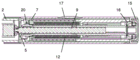
fig. 12 shows a sectional view of an injection device, comprising a drive mechanism according to a third embodiment of the invention during dose setting,
figure 13 shows a cross-sectional view of the injection device of figure 12 during dose dispensing,
figure 14 shows a detail of the drive mechanism of figure 12 prior to a zero dose position during dose dispensing,
figure 15 shows a detail of the drive mechanism of figure 12 at a zero dose position during dose dispensing,
fig. 16 shows a sectional view of an injection device, comprising a drive mechanism according to a fourth embodiment of the invention during dose setting,
figure 17 shows a detail of the drive mechanism of figure 16,
figure 18 shows a series of details of the drive mechanism of figure 16 prior to and at the zero dose position during dose dispensing,
figure 19 shows details of the drive mechanism of the fifth embodiment of the invention during dose setting,
figure 20 shows a series of details of the drive mechanism of figure 19 before and at a zero dose position during dose dispensing,
fig. 21 shows a sectional view of an injection device, comprising a drive mechanism according to a sixth embodiment of the invention during dose setting,
figure 22 shows a cross-sectional view of the injection device of figure 21 during dose dispensing,
fig. 23 a-23 c show a series of details of the drive mechanism of fig. 21 in a dose dialling mode (fig. 23a) and prior to (fig. 23b) and at a zero dose position (fig. 23c) during dose dispensing.
Detailed Description
An injection device 1 according to the invention is shown in an exploded view in fig. 1. The injection device 1 comprises a reservoir holder 2, a reservoir 3 and a drive mechanism. The drive mechanism comprises an outer housing 4, an inner housing 5, a dose dial sleeve as a dial member 6, a number sleeve as a display member 7, a drive sleeve as a drive member assembly 8, a lead screw 9, a bearing 10, a nut 11, a drive spring 12, a return spring 13, a dial grip 14, a dose button 15 and a clutch plate 16. All components are concentrically located about a common primary axis of the mechanism. In more detail, the drive member assembly 8 surrounds the lead screw 9, the torsion spring 12 surrounds the drive member 8, the dial member 6 and the inner housing 4 surround the torsion spring 12, the display member 7 surrounds the dial member 6, and the outer housing 4 surrounds the display member 7. Furthermore, the nut 11 and the clutch plate 16 are located between the drive member assembly 8 and the dial member 6. The drive member assembly 8 is depicted as comprising two components rigidly fixed together. Alternatively, an integrally molded drive member 8 may be provided. Therefore, in the following, the drive member 8 in question means an integrally formed drive member or a two-piece drive member.
The dose button 15 is axially constrained to the clutch plate 16. As can be seen in fig. 2, this may be achieved by a snap connection with a clutch plate 16, the clutch plate 16 having openings for receiving pins of the dose button 15. Thus, the dose button 15 may be rotatable relative to the clutch plate 16.
The dial grip 14 is axially constrained to the outer housing 4, the outer housing 4 forming the main body of the drive mechanism. Again, as shown in fig. 3, this may be achieved by a snap connection between the dial grip 14 and the outer housing 4. The dial grip 14 is rotationally constrained to the clutch plate 16. In the embodiment of fig. 1 to 6, a splined engagement is provided between the dial grip 14 and the clutch plate 16. The splined engagement is broken when the dose button 15 is depressed, i.e. when the dose button 15 and the clutch plate 16 are moved in an axial direction relative to the dial grip 14 and the outer housing 4.
The clutch plate 16 is further rotationally constrained to the dial member 6. Again, a spline joint may be provided between the clutch plate 16 and the dial member 6. The clutch plate 16 is further coupled to the drive member 8 via a ratchet joint, the connection taking place upon axial abutment. The ratchet combination provides a stop position between the dial member 6 and the drive member 8 corresponding to each dose unit and engages different inclined tooth angles during clockwise and counter-clockwise relative rotation between the dial member 6 and the drive member 8. The ratchet combination forms the second clutch 19 with corresponding teeth provided on the clutch plate 16 and the drive member 8, respectively.
The display member 7 is rotationally constrained to the dial member 6. Again, a splined joint may be provided between the display member 7 and the dial member 6. The display member 7 is further constrained to move along a helical path relative to the inner housing 5. This may be achieved by a threaded engagement between the display member 7 and the inner housing 5. Alternatively, a threaded joint may be provided between the display member 7 and the outer housing 4. The display member 7 is limited to movement between a zero dose position (distal position) and a maximum dose position (proximal position), which are defined by e.g. an end stop in the outer housing 4. As shown in more detail in fig. 4 to 7, the display member 7 has a flexible arm 21 at its distal end, the flexible arm 21 being provided with an abutment feature 22 at its free end.
The display member 7 is marked with a series of numbers which are visible through a window 17 in the outer housing 4. As an alternative to a transparent window, an aperture may be provided in the outer housing 4. The window 17 allows the user to indicate the dose of medicament dialled. The window 17 may be or may include a magnifying lens. The window 17 may be an integral part of the outer housing 4 or a separate component attached to the housing.
The nut 11 acts as a last dose nut and is interposed between the dial member 6 and the drive member 8. The nut 11 is rotationally constrained to the dial member 6, for example via a splined joint. Thus, the nut 11 is axially displaceable relative to the dial member 6. When a relative rotation is generated between the dial member 6 and the drive member 8, i.e. during dose setting and dose resetting, the nut 11 moves along a helical path relative to the drive member 8, e.g. via a threaded coupling. In an alternative embodiment, the nut 11 is splined to the drive member and is threaded to the dial member. An end stop (not shown) may be provided to limit the movement of the nut 11 in the track defined by the threaded engagement.
From this engagement portion, the drive member 8 extends all the way from the dial member 6 into engagement with the spline teeth of the inner housing 5. This provides a steering constraint of the drive member 8 to the inner housing 5. Releasable splined teeth engagement between the drive member 8 and the inner housing 5 form a first clutch 18, wherein the teeth are provided on the dial member 6 and the drive member 8, respectively.
When the dose button 15 is pressed, the spline teeth of the first clutch 18 are disengaged and the ratchet feature 20 is engaged, which provides audible and/or tactile feedback during dose dispensing.
The inner housing 5 is rigidly fixed to the outer housing 4. Thus, any rotation or any axial movement between the inner housing 5 and the outer housing 4 is not possible. The inner housing 5 and the outer housing 4 may be formed as one integral part, however for manufacturing reasons it is preferred to provide the housings as two separate parts of the outer housing 4 and the inner housing 5. As shown in more detail in fig. 4 to 7, the inner housing 5 is provided with a flexible arm 23, the flexible arm 23 having an abutment feature 24 at its free end.
The drive spring 12 is a torsion spring which is attached at one end to the inner housing 5 and at the other end to the dial member 6. The drive spring 12 is pre-wound at assembly so that when the mechanism is at the zero unit dialled, the drive spring 12 applies a torque to the dial member 6. The action of rotating the dial grip 14 to set a dose rotates the dial digit 6 relative to the inner housing 5 and winds up the drive spring 12.
The lead screw 9 is rotationally constrained to the drive member 8, for example via a splined joint. The lead screw 9 is forced to move axially relative to the drive member 8 when rotated. This is achieved by a threaded engagement between the lead screw 9 and the inner housing 5. The bearing 10 is axially constrained to the lead screw 9 and acts on a stopper inside the reservoir 3 during dose dispensing.
The axial position of the drive member 8, the clutch plate 16 and the dose button 15 is defined by the action of the return spring 13, which return spring 13 abuts the inner housing 5 and exerts a force on the drive member 8 in the proximal direction. This ensures that the clutch plate 16 is in splined engagement with the dial grip 14 and the drive member 8 is in splined engagement with the inner housing 5. The return spring 13 also acts to maintain engagement of the ratchet feature between the drive member 8 and the clutch plate 16, i.e. to maintain engagement of the second clutch 19 [ note: i do not determine that it is a problem, but the second clutch has not been described here. As an alternative, the function of the return spring 13 can be wholly or partly performed by the torsion spring 12.
The outer shell 4 provides a location for the reservoir 3 and the reservoir holder 2, and the reservoir holder 2 may be attached to the outer shell 4. Further, the outer case 4 includes: to rigidly constrain the joints of the inner housing 5 and the grooves on the outer surface of the outer housing 4 to axially retain the dial grip 14. Furthermore, a removable cover may be provided which fits over the tank holder 2 and resides via a clip feature.
In the following, the function and interaction of the above-mentioned components will be described in more detail in connection with an explanation of the drive mechanism in which the injection device 1 is used.
Fig. 2 and 3 and fig. 4 and 5 show the drive mechanism during dose setting and dose dispensing, respectively. As explained above, when the dose button 15 is pressed and the drive member 8 is moved in the axial direction, it acts on the flexible arms 23 on the inner housing 5, moving the flexible arms 23 radially outwards. In other words, in the unstressed state of the flexible arms 23 (during dose setting and dose resetting), the arms 23 and their abutment features 24 are in a radially inner position and are pushed outwards to a radially outer position during dose dispensing. For this purpose, the distal end of the drive member 8 may comprise a tapered or flared portion as shown in the figures. The radially inner position of abutment feature 24 is selected such that abutment feature 22 of display member 7 does not contact abutment feature 24 regardless of the position of display member 7.
Fig. 6 and 7 show the end of dose approaching during dose dispensing. As the display member 7 returns to its zero dose position (distal position), the flexible click arm 21 with its abutment feature 22 passes over the inner housing flexible arm 23 and its abutment feature 24, producing an audible click. Since the inner housing flexible arm 23 is moved outwards only during dispensing, the set torque is not affected and no clicking sound is generated when the dose is dialled down to zero units during dose resetting.
With respect to the first clutch 18 and the second clutch 19, there are two generally different states of the drive mechanism of the injection device 1, which are shown in fig. 2 and 3, respectively. Fig. 2 shows the drive mechanism in a rest state, which is a state when it is assumed that the user does not exert any force under the drive mechanism. In this stationary state, the first clutch 18 couples the drive member 8 to the inner housing 5, and the second clutch 19 allows relative rotation between the clutch plate 16 and the drive member 8. However, in order to rotate the clutch plate 16 relative to the drive member 8, a torque must be provided to overcome the resistance of the ratchet feature, i.e. the clutch plate 6 cannot rotate freely relative to the drive member 8. If the user presses the dose button 15, the second state shown in fig. 3 results. This causes the first clutch 18 to disengage so that the drive member 8 is free to rotate relative to the inner housing 5, while the second clutch 19 is coupled to prevent relative rotation between the drive member 8 and the clutch plate 16.
With the device in the rest state, the display member 7 is positioned in its zero dose abutment with the inner housing 5 and the dose button 15 is not depressed. The dose indicia "0" on the dial member 7 is visible through the window 17 on the outer housing 4. The drive spring 12, to which a number of pre-wound turns are applied during assembly of the device, applies a torque to the dial member 6. The dial member 6 is prevented from rotating under torque by its ratchet engagement with the drive member 8 (second clutch 19). The drive member 8 is prevented from rotating by the interlock provided by the engagement of the spline teeth on the drive member 8 and the inner housing 5 (first clutch 18). The return spring 13 maintains the first clutch 18 in its coupled state by pushing the drive member 8 in the proximal direction. However, as the teeth of the second clutch 19 pass each other upon relative rotation of the drive member 8 and the clutch plate 16, the drive member 8 is free to displace in the distal direction against the force of the return spring 13. The height of the teeth of the second clutch 19 is smaller than the axial height of the splines of the first clutch 18. Therefore, the first clutch 18 is maintained in its coupled state even if the teeth of the second clutch 19 pass each other.
The user selects a variable dose of medicament by rotating the dial grip 14 clockwise, which rotation produces the same rotation in the dial member 6. The rotation of the dial member 6 causes the drive spring 12 to wind up, increasing the energy stored in the drive spring 12. The drive member 8 is still prevented from rotating due to its splined teeth engaging with the inner housing 5 (first clutch 18 coupled). Therefore, relative rotation must occur between the clutch plate 16 and the drive member 8 via the ratchet engagement of the second clutch 19.
The user torque required to rotate the dial grip 14 is the sum of the torque required to wind up the drive spring 12 and the torque required to overrun the ratchet feature of the second clutch 19. The return spring 13 is designed to provide an axial force to the ratchet feature and bias the components (drive member 8, clutch plate 16, dose button 15) away from the reservoir end of the injection device 1. The axial load acts to maintain the drive member 8 in engagement with the ratchet teeth of the clutch plate 16. The torque required to override the ratchet teeth is a result of the axial load applied by the return spring 13, the clockwise ramp angle of the ratchet, the coefficient of friction between the mating surfaces, and the average radius of the ratchet features.
When the user rotates the dial grip 14 sufficiently to increment the mechanism by one unit, the dial member 6 rotates relative to the drive member 8 by one set of ratchet teeth. At this point, the ratchet teeth reengage into the next detent position. An audible click is generated by the ratchet re-engaging and tactile feedback is provided by a change in the desired torque input. Thus, the second clutch 19 forms a ratchet click.
The relative rotation of the dial member 6 and the drive member 8 causes the last dose nut 11 to follow a threaded path towards its last dose abutment on the dial member 6. Rotation of the dial member 6 further generates rotation in the display member 7, the display member 7 following its helical path defined by its engagement with the inner housing 5. The dose indicia corresponding to the x units become aligned with the window 17 in the outer housing 4. The device is now set to deliver x units of liquid medicament.
With no user torque applied to the dial grip 14, the dial member 6 is now prevented from rotating under the torque applied by the drive spring 12 solely by the ratchet engagement between the clutch plate 16 and the drive member 8 (second clutch 19). The torque required to overrun the ratchet in the counterclockwise direction is a result of the axial load applied by the return spring 13, the counterclockwise ramp angle of the ratchet, the coefficient of friction between the mating surfaces, and the average radius of the ratchet features. The torque required to override the ratchet must be greater than the torque applied to the dial member 6 (and hence the clutch plate 16) by the drive spring 12. The ratchet ramp angle thus increases in the counterclockwise direction to ensure that this is the case.
The user may now choose to increase the selected dose by continuing to rotate the dial grip 14 in the clockwise direction. The process of overriding the ratchet engagement between the dial member 6 and the drive member 8 is repeated for each dose unit. For each dosage unit, additional energy is stored within the drive spring 12 and, for each unit dialed, audible and tactile feedback is provided by re-engagement of the ratchet teeth. As the torque required to wind up the drive spring 12 increases, the torque required to rotate the dial grip 14 increases. The torque required to override the ratchet in the counter-clockwise direction must therefore be greater than the torque applied to the dial member 6 by the drive spring 12 when the maximum dose has been reached.
If the user continues to increase the selected dose until the maximum dose limit is reached, the display member 7 engages with its maximum dose abutment on the outer housing 4, which prevents further rotation of the display member 7, dial member 6, clutch plate 16 and dial grip 14. At this point the maximum dose indicia on the display member 7 is aligned with the window 17 in the outer housing 4.
Depending on how many units have been delivered by the drive mechanism, the last dose nut 11 may have its last dose abutment (i.e. end stop) in contact with the dial member 6 during dose selection. The abutment prevents further relative rotation of the dial member 6 and the drive member 8 and thus limits the dose that can be selected. The position of the last dose nut 11 is determined by the total number of relative rotations that have been generated between the dial member 6 and the drive member 8 each time a dose is set by the user.
With the mechanism in a state where a dose has been selected, the user can deselect or reset any number of units from the dose. Deselecting a dose is achieved by the user rotating the dial grip 14 counter-clockwise. The torque applied by the user to the dial grip 14, when combined with the torque applied by the drive spring 12, is sufficient to override the ratchet 19 between the clutch plate 16 and the drive member 8 in a counter-clockwise direction. When the ratchet is overridden, a counter-clockwise direction is created in the dial member 6 (via the clutch plate 16), which returns the display member 7 towards the zero dose position and unwinds the drive spring 12. Relative rotation between the dial member 6 and the drive member 8 causes the last dose nut 11 to return along its helical path, away from the last dose abutment.
With the mechanism in a state where a dose has been selected, the user can activate the drive mechanism to start delivering a dose (dose dispensing). Delivery of the dose is initiated by the user pressing a dose button 15 on the top (proximal) end of the drive mechanism. When the dose button is pressed, it moves in the axial direction, acting on the clutch plate 16, which clutch plate 16 in turn acts on the drive member 8. The clutch plate 16 disengages its splined teeth from the dial grip 14 and, thereafter, the drive member 8 disengages its splined teeth (first clutch 18) from the inner housing 5.
When the splined engagement of the first clutch 18 between the inner housing 5 and the drive member 8 is disengaged, the engagement preventing rotation of the drive member 8 during dose selection is removed. The torque applied to the dial member 6 from the drive spring 12 is transmitted into the drive member 8 via the ratcheting engagement of the second clutch 19. This torque urges the drive member 8 and, due to the relative engagement of the drive member 8 and the inner housing 5, advances the lead screw 9. Axial displacement of the lead screw 9 forces the liquid medicament to be delivered from the mechanism by the action of the bearing 10 contacting and displacing a bung within the reservoir 3.
The ratchet feature 20 of the inner housing 5 comprises a clicker arm (not shown). The clicker arm is a flexible cantilever beam integrated into the inner housing 5, radially engaging with splined ratchet teeth in the drive member 8. The ratchet teeth 18b spacing corresponds to the rotation of the drive member 8 required to deliver a single dose unit. During dispensing, as the drive member 8 is rotated, the spline feature engages with the clicker arm to produce an audible click with each dose unit delivered. The torque required to override the clicker arm is a result of the ratchet tooth profile, the stiffness of the cantilever beam and the nominal interference between the clicker arm and the ratchet. The clicker arm combination is designed such that the torque required for override is significantly less than the torque provided by the drive spring 12.
Rotation of the dial member 6 also causes the display member 7 to return along its helical path towards the zero dose abutment with respect to the inner housing 5. As the user continues to press the dose button 15, delivery of the dose continues via the mechanical interaction described above. If the user releases the dose button 15, the return spring 13 returns the dose button 15 to its rest position via the drive member 8 and the clutch plate 16, so that the drive member 8 becomes rotationally restrained and delivery of the dose stops.
With the dose button 15 depressed, delivery of the dose continues until the display member 7 reaches its zero dose abutment with the inner housing 5. The torque applied to the dial member 6 is reacted by the abutment of the display member 7 and the dial member 6, with the clutch plate 16 and the drive member 8 being prevented from further rotation. During delivery of a dose, the drive member 8 and the dial member 6 rotate together such that no relative movement occurs in the last dose nut 11. Thus, the last dose nut 11 only travels towards its abutment on the dial member 6 during dose setting and away from the end stop during dose resetting.
Once delivery of the dose is stopped by the display member 7 returning to the zero dose abutment, the user may release the dose button 15, which will re-engage the first clutch 18 between the inner housing 5 and the drive member 8. The mechanism now returns to the rest state.
The spline teeth on the drive member 8 or the inner housing 5 may be inclined such that when the dose button 15 is released, re-engagement of the spline teeth causes the drive member 8 to rewind slightly, thereby disengaging the display member 7 from the zero dose stop abutment in the inner housing 5. This eliminates the effect of play in the drive mechanism (e.g. due to tolerances) which would otherwise cause the lead screw 9 to advance slightly and dispense medicament when the drive mechanism is dialled to provide a subsequent dose. This is because the zero dose stop of the display member 7 no longer constrains the mechanism, but rather the constraint returns to the splines between the drive member 8 and the inner housing 5.
A second embodiment of a drive mechanism suitable for use with the injection device 101 is shown in figures 8 to 11. The injection device 101 comprises a reservoir holder 102, a reservoir 103 containing a medicament, a cap (not shown, optionally included) and a drive mechanism. The drive mechanism comprises an outer housing 104 with a window 117, an inner housing 105, a dial member 106 (dial sleeve), a display member 107 (number sleeve), a drive member 108 (drive sleeve), a lead screw 109, a bearing 110, a nut 111, a torsion spring 112, a dial grip 114, a first clutch 118, a second clutch 119 (clutch plate), a ratchet feature 120, a clutch spring 125, a trigger clutch 126, a trigger 127 and a trigger cover 128.
Similar to the first embodiment, all components are concentrically positioned about a common major axis of the drive mechanism, except for trigger 127 and trigger cover 128.
The dial grip 114 is axially constrained to the outer housing 104. It is rotationally constrained to the dial member 106 via a splined engagement. As shown in fig. 11, the dial member 106 is coupled to the drive member 108 via a ratchet coupling (second clutch 119), which occurs upon axial abutment. The ratchet provides a stop position between the dial member 106 and the drive member 108 corresponding to each dose unit and engages different ramped tooth angles during clockwise and counter-clockwise relative rotation. Corresponding ratchet teeth are provided on the facing surfaces of the dial member 106 and the drive member 108.
The display member 107 is rotationally constrained to the dial member 106 via a spline joint. It is constrained to move along a helical path via a threaded engagement with respect to the inner housing 105. The display member 107 is marked with a series of numbers which are visible through a window 117 in the outer housing 104 to indicate the dose of dialled medicament.
The last dose nut 111 is located between the dial member 106 and the drive member 108. It is rotationally constrained to the dial member 106 via a splined engagement. When relative rotation is generated between the dial member 106 and the drive member 108, the last dose nut 111 moves in a helical path relative to the drive member 108 via a threaded engagement.
The drive member 108 extends from engagement with the dial member 106 all the way to engagement with the ratchet of the inner housing 105, which occurs upon axial abutment. The ratchet combination defines the axial position of the drive member 108 at the end of dose delivery and is included to improve dose accuracy. The drive member 108 is rotationally constrained to the housing via engagement of a set of spline teeth when the trigger 127 is triggered. It provides a clicker arm that acts radially on a set of ratchet teeth in the inner housing 105. It moves along a helical path relative to the lead screw 109 via a threaded engagement. The drive member 108 provides an axial abutment with the inner housing 105, which reacts to the force applied by the lead screw 109 to the reservoir 103 when the drive mechanism is dispensed.
The torsion spring 112 is attached at one end to the inner housing 105 and at the other end to the dial member 106. The attachments at both ends are configured to transfer tangential forces resulting from the torsion of the spring 112 and axial forces along the main axis (longitudinal axis) of the drive mechanism. The torsion spring 112 is pre-wound at assembly so that when the mechanism is at the zero unit dialed, the drive spring 12 applies a torque to the dial member 106. The action of rotating the dial grip 114 to set a dose rotates the dial grip 114 relative to the inner housing 105 and winds up the torsion spring 112. The torsion spring 112 is designed to exert an axial force that acts to pull the dial member 106 towards the inner housing 105.
The lead screw 109 is rotationally constrained to the inner housing 105 via a splined engagement. When drive member 108 moves relative to inner housing 105, lead screw 109 is forced to move axially relative to inner housing 105 by its threaded engagement with drive member 108. The bearing 110 (washer) is axially constrained to the lead screw 109 and acts on a stopper within the liquid medicament reservoir 103.
The inner housing 105 is rigidly constrained to the outer housing 104. Axial abutment with the drive member 108 is provided by a pair of flexible arms that flex during assembly. A pair of abutment features are provided at both ends of the threaded engagement with the display member 107 that limit the range of travel of the display member 107. These abutments provide a zero dose stop and a maximum dose stop. The inner housing 105 provides rotational restraint to the trigger clutch 126 and provides an axial abutment against the axial force generated by the clutch spring 125. The axial position of the trigger clutch 126 is defined by the action of the clutch spring 125 and its abutment with the trigger 127, the clutch spring 125 forcing the trigger clutch 126 towards the reservoir end (distal end) of the drive mechanism. When axially positioned at its rest position, the trigger clutch 126 engages the splined teeth on the drive member 108, which constrains the rotation of the drive member 108. The spline teeth on the trigger clutch 126 and the corresponding spline teeth on the drive member 108 form the first clutch 118. Engagement and disengagement of the first clutch 118 is illustrated in fig. 8 and 9.
A clutch spring 125 is located between the inner housing 105 and the trigger clutch 126 and acts to force the trigger clutch 126 towards the reservoir end of the drive mechanism. The trigger 127 is constrained to pivot in the outer housing 104. It has an integral spring element that acts to rotate the trigger 127 away from the outer housing 104. When the trigger 127 is depressed, an abutment with the trigger clutch 126 is created, which moves the trigger clutch 126 axially toward the inner housing 105.
The outer housing 104 provides a location for the liquid medicament reservoir 103, a pivot for the trigger 127, a joint to rigidly restrain the inner housing 105, a window 117 through which the dose number on the display member 107 may be viewed, and a groove on its outer surface to axially retain the dial indicator grip 114. The trigger cover 128 may clip into the outer housing 104 and retain the trigger 127 within its pivotal interface with the outer housing 104. A removable cover fits over the reservoir holder element 102 and is retained to the outer housing 104 via a clip when the drive mechanism is not in use. When the lid is fitted to the outer housing 104, a mechanical interlock with the trigger 127 is created, preventing the trigger 127 from being depressed from its rest position.
Similar to the first embodiment, the display member 107 is provided with a flexible arm 121, the flexible arm 121 having an abutment feature 122 on its distal end. In addition, the trigger clutch 126 is provided with a corresponding abutment feature 124.
With the device in the rest state, the display member 107 is positioned in a zero dose abutment with the inner housing 105 and the trigger 127 is not depressed. The dose marking "0" on the display member 107 is visible through a window 117 on the outer housing 104. As shown in fig. 8 and 10, the trigger clutch 126 is in a distal position, which is a position where dose setting and dose resetting is performed.
When the user rotates the dial grip 114, the dial member 106 rotates relative to the drive member 108. Rotation of the dial member 106 produces rotation in the display member 107, the display member 7 following its helical path defined by its combination with the inner housing 105. The device is now arranged to deliver a liquid medicament. The user may now choose to increase the selected dose by continuing to rotate the dial grip 114 in the clockwise direction. With the drive mechanism in a state where a dose has been selected, the user can deselect any number of units from the dose. Deselecting a dose is achieved by the user rotating the dial grip 114 in a counter-clockwise direction, which returns the display member 107 towards the zero dose position. However, with the trigger clutch still in its distal position, the abutment features 122, 124 do not contact each other during dose resetting, as the abutment feature 124 is thrown distally from the track of the display member 107 and its abutment feature 122.
With the mechanism in a state where a dose has been selected, the user can activate the gearing mechanism to start delivering the dose. Delivery of the dose is initiated by the user pressing a trigger 127 on one side of the drive mechanism. As the trigger is depressed, an abutment is created with the trigger clutch 126, which acts to move the trigger clutch axially away from the reservoir 103 (i.e., in a proximal direction) against the action of the clutch spring 125. When the trigger 127 is fully depressed, sufficient axial travel has occurred at the trigger clutch 126 to move the abutment feature 124 into the path of the abutment feature 122 of the display member 107. As the display member 107 approaches its zero dose stop, the free end of the clicker arm 121 rides up the ramp of the abutment feature 124. At the zero position, the clicker arm 121 clears the ramp and returns to its original position, providing tactile and audible feedback to the user. Thus, the end of dose click feature is only engaged during dispensing.
Fig. 12 to 15 depict a third embodiment. The injection device 201 includes a reservoir 203, a housing 204, and a base 205 (inner and outer housing main bodies). A dial gear 206 (dial member) is splined to the number wheel 207 and is translated in an axial direction by a button 215. Furthermore, during dose dispensing, the dial gear 206 is splined to the release gear 208 (drive member). The number wheel 207 is a display member that displays numbers. A prism 217 is provided, the prism 217 magnifying and reflecting the numbers displayed on the number wheel 207. The last dose nut 211 is splined to the dial gear 206 and is threaded to the release gear 208. The tape is retained in the tape drum and retaining ring and passes over rollers in the base 205. The compression spring 212 is arranged as a pre-tensioned drive spring acting on the piston rod 209. The spring 212 fits between the base 205 and the retainer ring. The release gear 208 is toothed to the tape drum and resides in the seat 205 during dose setting, while it is splined to the dial gear 206 during dose dispensing.
The dial 214 is rotationally coupled to the dial gear via face teeth, which rotates clockwise to set a dose. A stop between the dial 214 and the front housing member provides discrete dose setting positions. The release gear 208 is rotationally fixed by the base 205. The number wheel 207 is driven directly from the dial gear 206, providing a zero dose stop and a maximum dose stop between the number wheel and the base. The last dose nut 211 is rotated by the dial gear 206 along the thread on the release gear towards the last dose stop. In a similar manner, the set dose may be reduced by rotating the dial counterclockwise.
To dispense a dose, the button 215 is pressed, locking the dial 214. The dial gear 206 engages the release gear 208 and pushes the locking arm of the base 205 out of engagement with the release gear 208, allowing the release gear 208 to rotate under the action of the spring 212. Rotation of the release gear 208 allows the belt drum to rotate, releasing the belt and allowing the spring 212 to act on and advance the reservoir stopper.
During dose dispensing, i.e. only when the dial gear 206 is pressed against the base 205, a ramp feature 222 on the dial gear 206 engages with a clicker arm 223 on the base to provide an end of dose click. These features do not engage during dose setting and dose resetting, so the "drop" at the end of the dose will be very accurate. This is shown in fig. 14 and 15 as a partial cross section through the base 205 and the dial gear 206. The clicker arm 223 falls off a steep inclined ramp and thus hits the dial gear 206 producing a distinctive click.
A fourth embodiment is depicted in fig. 16-18. The main components of the injection device 301 are a reservoir 303, an outer housing 304, an inner housing body 305, a drive sleeve 308 (drive member), a dial sleeve 306 (dial member), a piston rod in the form of a lead screw 309, a dose dial grip 314 and a spring 312, the spring 312 being a flat spring or a tensioning element.
To set a dose, the user rotates the dose dial grip 314 clockwise. This causes the dial sleeve 306 to rotate, moving the dose nut 307 away from its zero dose stop feature and increasing the displayed dose. In the example of figure 16, the dose counter consists of a dial sleeve 306 printed with units and a tens wheel which is incremented by the action of an indexing gear, once per revolution. The last dose nut 311 is rotated on the threads on the drive sleeve 308 towards the last dose stop. The drive sleeve 308 is locked by its splined engagement with the housing 304, thus preventing it from being rotated by the spring 312.
To dispense a dose, the dose dial grip 314 is pressed. This disengages the dose dial grip 314 from the dial sleeve 306 so that the dose dial grip 314 does not rotate during dispensing. The drive sleeve 308 moves axially with the dose dial grip 314 out of splined engagement with the inner body 305, allowing the spring 312 to rotate the drive sleeve 308. The drive sleeve 308 rotates the lead screw 309 forward through the threads in the inner body 305 to advance the reservoir stopper. The odometer counter mechanism and dose nut 307 are then returned towards their zero dose position.
A spring arm 321 with an abutment feature is provided on the dose nut 307. During dose dispensing, as the dial sleeve 306 rotates counterclockwise toward the zero dose position, the spring arm 321 passes over the zero unit stop feature on the dial sleeve and flexes radially outward. When the zero unit stop passes the end of the spring arm 321, the stored energy is released, moving the spring arm 321 radially inward, creating a click when the spring arm 321 strikes the dial sleeve 306. When dialling from 0 unit increments to 1 unit, the spring arm 321 is axially forced by a ramp on the dial sleeve 306 and returns to its unstressed position. This will not produce any audible feedback.
An alternative fifth embodiment is shown in fig. 19 and 20, where the main functions and components are as described above with respect to the fourth embodiment. As the dial sleeve 306 is rotated counterclockwise toward zero units, the spring arm 323 on the dial sleeve 306 is deflected in an axial direction by a ramp feature on the dose nut 307. As the ramp feature passes the end of the spring arm 323, the stored energy is released, moving the spring arm 323 in an axial direction, creating a clicking sound as it strikes the exterior of the dose nut 307 thread. When dialling from 0 unit increments to 1 unit, the opposite side of the ramp feature on the dose nut urges the spring arm 323 in the axial direction and causes it to fall off the edge along the spring arm 323, but no contact surface produces a clicking sound. Throughout the remainder of the stroke of the dose nut 307, the dose nut 307 passes away from the spring arm 323 and so they are no longer in contact.
A sixth embodiment is depicted in fig. 21-23, where the main functions and components are as described above with respect to the fourth embodiment. The main components of the injection device 401 are a reservoir 403, an outer housing 404, an inner housing body 405, a drive sleeve 408 (drive member), a dial sleeve 406 (dial member), a piston rod in the form of a lead screw 409, a dose dial grip 414 and a spring 412, the spring 312 being a flat spring or a tensioning element. However, unlike the fourth embodiment, in which the lead screw 309 is arranged coaxially with the dial sleeve 306 and the drive sleeve 308, in the sixth embodiment the lead screw 409 is arranged spaced from and parallel to the drive sleeve 408 and the dial sleeve 406. The drive tube 430 is geared to the drive sleeve 408, which is arranged to be splined to the driven member of the lead screw 409. Further, a clicker 431 is splined to the housing 404 and is captured by the dial grip 414, which is disposed coaxially with the drive sleeve 408. During dose setting and dose resetting, the dial sleeve 406 is splined to the number sleeve 407 and further splined to the dial grip 414.
The dial grip 414 rotates to set a dose. The dial grip 414 rotates the dial sleeve 406, which in turn rotates the number sleeve 407, causing it to move away from its zero unit stop and display the desired dose through a window in the housing 404. The drive sleeve 408 is constrained via a splined engagement to the housing 404 during dose setting. The spring 412 applies a permanent torque to the drive sleeve 408. Tactile and audible feedback is provided by the interaction of the dial grip 414 and the clicker 431. The clicker 431 is splined to the housing 404 and with each dose increment dialed, the clicker 431 moves back and forth in an axial direction under the action of the trigger spring.
To dispense a dose, the upper end of the dial grip 414 is pressed by the user. The dial grip 414 is first disengaged from the dial sleeve 406 such that the dial grip 414 does not rotate during dispensing. This causes the drive sleeve 408 to be displaced towards the distal end of the device. The drive sleeve 408 then engages with the splines on the dial sleeve 406. The drive sleeve 408 is then disengaged from the housing 404, allowing it to be rotated by the spring 412. The drive sleeve 408 rotates the drive tube 430, which in turn rotates the lead screw 409, causing the lead screw 409 to advance axially through the threads in the housing 404, displacing the stopper in the reservoir.
Feedback at the end of dose is provided by the interaction between the number sleeve 407 and the clicker 431. The clicker 431 is moved between two different axial positions for dose setting or resetting and dose dispensing. This allows the flexible feature 424 on the clicker 431 to interact with the feature 422 on the number sleeve 407 during dispensing rather than during dialing so that the dial torque is not affected.
Reference numerals:
1,101,201,301,401 injection device
2 tank holder
3,103,203,303,403 storage tank
4,104,204,304,404 outer casing (Main body)
5,105,205,305,405 inner case
6,106,206,306,406 dialing component (dose dialing sleeve)
7,107,207,407 display component (digital sleeve)
307 dosage nut
8,108,208,308,408 Driving component (Driving sleeve)
9,109,209,309,409 piston rod (lead screw)
10,110 support (gasket)
11,111,211,311,411 last dose nut
12,112,212,312,412 spring
13 return spring
14,114,214,314,414 hand-dials
15,215 dose button
16 clutch plate
17,117 Window
217 prism
18,118 first clutch
19,119 second clutch (clicker ratchet)
20,120 ratchet (clicker)
21,121,321 Flexible arm
22,122,222,422 abutment features
23,223,323 Flexible arm
24,124,324,424 abutment feature
125 ratchet spring
126 trigger clutch
127 trigger
128 trigger cover
129 axial ratchet
430 drive tube
431 clicker
Claims (16)
1. A drive mechanism for an injection device, the mechanism comprising a housing (4; 104; 204; 304; 404) and a dosing member (7; 107; 206; 306; 407), the dosing member (7; 107; 206; 306; 407) being rotatable relative to the housing between a zero dose position and a maximum dose position during dose setting, dose resetting and dose dispensing, the mechanism further comprising an insert (5; 126; 205; 307; 431) rotationally constrained to the housing, wherein the dosing member (7; 107; 206; 306; 407) and the insert (5; 126; 205; 307; 431) each comprise at least one abutment feature (22, 24; 122, 124; 222; 321; 422, 424) which comes into contact with each other when the dosing member (7; 107; 206; 306; 407) reaches its zero dose position during dose dispensing, and wherein the audible and/or tactile feedback is generated by contact of the abutment feature (22, 24; 122, 124; 222; 321; 422, 424), characterized in that the mechanism further comprises a further component (8; 126; 431), axial movement of said further component (8; 126; 431) causing the mechanism to switch between a mode in which reaching a zero dose position at the end of the dose dispensing process is indicated by the feedback signal, and a mode in which reaching a zero dose position is not indicated by said feedback signal.
2. The drive mechanism according to claim 1, wherein in another mode, reaching a zero dose position during dose resetting is not indicated by the feedback signal.
3. The drive mechanism according to claim 1, wherein the abutment features (22, 24; 122, 124; 222; 321; 422, 424) are in contact with each other only when the dosing member (7; 107; 206; 306; 407) reaches its zero dose position during dose dispensing.
4. The drive mechanism according to any one of claims 1 to 3, wherein the further component (8; 126) radially flexes one of the abutment features (24; 124) when the further component (8; 126; 431) is in its dose dispensing position.
5. The drive mechanism according to any one of claims 1 to 3, comprising an inner body (5) and a number sleeve (7), the inner body (5) being rotationally constrained to the housing (4), the number sleeve (7) being in threaded engagement with the housing (4) or the inner body (5) and being movable between a zero dose position and a maximum dose position, wherein the inner body (5) comprises a flexible arm (23), the flexible arm (23) having a first abutment feature (24), the number sleeve (7) comprising a corresponding second abutment feature (22), the second abutment feature (22) contacting the first abutment feature (24) when the number sleeve (7) reaches its zero dose position during dose dispensing.
6. The drive mechanism according to any one of claims 1 to 3, comprising a trigger clutch (126) and a number sleeve (107), the trigger clutch (126) being rotationally constrained to the housing (104), the number sleeve (107) being in threaded engagement with the housing (104) and being movable between a zero dose position and a maximum dose position, wherein the trigger clutch (126) comprises a first abutment feature (124), the number sleeve (107) comprising a corresponding second abutment feature (122), the second abutment feature (22) contacting the first abutment feature (124) when the number sleeve (107) reaches its zero dose position during dose dispensing.
7. The drive mechanism according to claim 5, wherein the number sleeve (7) and its second abutment feature (22) move along a helical path during dose setting, dose resetting and dose dispensing, and wherein the first abutment feature (24) is in the helical path only during dose dispensing.
8. The drive mechanism according to claim 6, wherein the number sleeve (107) and its second abutment feature (122) move along a helical path during dose setting, dose resetting and dose dispensing, and wherein the first abutment feature (124) is in the helical path only during dose dispensing.
9. The drive mechanism according to claim 7, further comprising a drive member (8), the drive member (8) being axially displaceable relative to the housing (5) between a dose setting position and a dose dispensing position, wherein the first abutment feature (24) is on the flexible arm (23) and in a stress-free state of the flexible arm (23) the first abutment feature (24) is not in a helical path, and wherein in its dose dispensing position the drive member (8) urges the flexible arm (23) and its first abutment feature (24) into the helical path.
10. The drive mechanism according to claim 8, further comprising a trigger (127), the trigger (127) for axially displacing the trigger clutch (126) relative to the housing (104) between a dose set position and a dose dispense position, wherein in the dose set position of the trigger clutch (126) the first abutment feature (124) is not in the helical path, and wherein the trigger (127) in its dose dispense position urges the trigger clutch (126) and its first abutment feature (124) into the helical path.
11. The drive mechanism according to claim 1, comprising a dose nut (307) and a dial sleeve (306), the dose nut (307) being axially displaceable between a zero dose position and a maximum dose position and rotationally constrained to the housing (304), the dial sleeve (306) being rotatable relative to the housing (304), wherein the dose nut (307) comprises a flexible finger (323) having a first abutment feature (324), the flexible finger (323) flexing during dose dispensing, and the flexible finger (323) striking a second abutment feature (322) provided on the dial sleeve (306) when the dose nut (307) reaches its zero dose position.
12. The drive mechanism according to claim 1, comprising a dose nut (307) and a dial sleeve (306), the dose nut (307) being axially displaceable between a zero dose position and a maximum dose position and rotationally constrained to the housing (304), the dial sleeve (306) being rotatable relative to the housing (304), wherein the dose nut (307) comprises a flexible finger portion (321) having a first abutment feature, the flexible finger portion (321) flexing during dose dispensing, and the flexible finger portion (321) striking a second abutment feature provided on the dose nut (307) when the dose nut (307) reaches its zero dose position.
13. The drive mechanism according to any one of claims 1 to 3, comprising a clicker (431) and a number sleeve (407), the clicker (431) being rotationally constrained to the housing (404), the number sleeve (407) being in threaded engagement with the housing (404) and being movable between a zero dose position and a maximum dose position, wherein the clicker (431) comprises a first abutment feature (424), the number sleeve (407) comprising a corresponding second abutment feature (422), the second abutment feature (422) contacting the first abutment feature (424) when the number sleeve (407) reaches its zero dose position during dose dispensing.
14. The drive mechanism according to claim 13, wherein the number sleeve (407) and its second abutment feature (422) move along a helical path during dose setting, dose resetting and dose dispensing, and wherein the clicker (431) is axially displaceable relative to the housing (404) such that the first abutment feature (424) is in the helical path only during dose dispensing.
15. The drive mechanism according to claim 14, further comprising a dial grip sleeve (414), the dial grip sleeve (414) being axially displaceable relative to the housing (404) between a dose set position and a dose dispense position, wherein in the dose set position of the dial grip sleeve (414) the first abutment feature (424) is not in the helical path, and wherein in its dose dispense position the dial grip sleeve (414) axially displaces the clicker (431) to urge its first abutment feature (424) into the helical path.
16. An injection device comprising a drive mechanism according to any one of claims 1 to 15 and a reservoir (3; 103; 203; 303; 403) containing a medicament.
Applications Claiming Priority (3)
| Application Number | Priority Date | Filing Date | Title |
|---|---|---|---|
| EP13182765 | 2013-09-03 | ||
| EP13182765.1 | 2013-09-03 | ||
| PCT/EP2014/068656 WO2015032783A1 (en) | 2013-09-03 | 2014-09-03 | Drive mechanism and injection device herewith |
Publications (2)
| Publication Number | Publication Date |
|---|---|
| CN105492044A CN105492044A (en) | 2016-04-13 |
| CN105492044B true CN105492044B (en) | 2021-03-09 |
Family
ID=49115386
Family Applications (1)
| Application Number | Title | Priority Date | Filing Date |
|---|---|---|---|
| CN201480048167.3A Expired - Fee Related CN105492044B (en) | 2013-09-03 | 2014-09-03 | Drive mechanism and injection device with same |
Country Status (7)
| Country | Link |
|---|---|
| US (1) | US10238807B2 (en) |
| EP (1) | EP3041538B1 (en) |
| JP (1) | JP6510528B2 (en) |
| CN (1) | CN105492044B (en) |
| DK (1) | DK3041538T3 (en) |
| HK (1) | HK1222817A1 (en) |
| WO (1) | WO2015032783A1 (en) |
Families Citing this family (1)
| Publication number | Priority date | Publication date | Assignee | Title |
|---|---|---|---|---|
| JP6654256B2 (en) * | 2016-05-27 | 2020-02-26 | エス・ハー・エル・メディカル・アクチェンゲゼルシャフトShl Medical Ag | Actuation mechanism |
Citations (4)
| Publication number | Priority date | Publication date | Assignee | Title |
|---|---|---|---|---|
| CN101107032A (en) * | 2005-01-25 | 2008-01-16 | 诺和诺德公司 | An injection device with an end of dose feedback mechanism |
| CN101115520A (en) * | 2005-02-11 | 2008-01-30 | 诺和诺德公司 | Injection device |
| WO2011060786A1 (en) * | 2009-11-20 | 2011-05-26 | Moeller Claus Schmidt | Spring actuated dose delivery device |
| CN102740910A (en) * | 2009-11-20 | 2012-10-17 | 克劳斯·施密特·默勒 | Injection device without a gearing |
Family Cites Families (51)
| Publication number | Priority date | Publication date | Assignee | Title |
|---|---|---|---|---|
| US533575A (en) | 1895-02-05 | wilkens | ||
| DE3715258C2 (en) | 1987-05-08 | 1996-10-31 | Haselmeier Wilhelm Fa | Injection device |
| GB8713810D0 (en) | 1987-06-12 | 1987-07-15 | Hypoguard Uk Ltd | Measured dose dispensing device |
| US5226895A (en) | 1989-06-05 | 1993-07-13 | Eli Lilly And Company | Multiple dose injection pen |
| GB9007113D0 (en) | 1990-03-29 | 1990-05-30 | Sams Bernard | Dispensing device |
| US5226896A (en) | 1990-04-04 | 1993-07-13 | Eli Lilly And Company | Dose indicating injection pen |
| AU641206B2 (en) | 1991-01-22 | 1993-09-16 | Eli Lilly And Company | Multiple dose injection pen |
| ES2074771T3 (en) | 1991-07-24 | 1995-09-16 | Medico Dev Investment Co | INJECTOR. |
| DK175491D0 (en) | 1991-10-18 | 1991-10-18 | Novo Nordisk As | APPARATUS |
| US5279585A (en) | 1992-02-04 | 1994-01-18 | Becton, Dickinson And Company | Medication delivery pen having improved dose delivery features |
| US5271527A (en) | 1992-04-02 | 1993-12-21 | Habley Medical Technology Corporation | Reusable pharmaceutical dispenser with full stroke indicator |
| US5300041A (en) | 1992-06-01 | 1994-04-05 | Habley Medical Technology Corporation | Dose setting and repeating syringe |
| US5391157A (en) | 1992-10-20 | 1995-02-21 | Eli Lilly And Company | End of dose indicator |
| US5378233A (en) | 1992-11-18 | 1995-01-03 | Habley Medical Technology Corporation | Selected dose pharmaceutical dispenser |
| US5320609A (en) | 1992-12-07 | 1994-06-14 | Habley Medical Technology Corporation | Automatic pharmaceutical dispensing syringe |
| FR2701211B1 (en) | 1993-02-08 | 1995-05-24 | Aguettant Lab | DOSING INSTRUMENT, ESPECIALLY INJECTION |
| US5383865A (en) | 1993-03-15 | 1995-01-24 | Eli Lilly And Company | Medication dispensing device |
| ZA941881B (en) | 1993-04-02 | 1995-09-18 | Lilly Co Eli | Manifold medication injection apparatus and method |
| US5582598A (en) | 1994-09-19 | 1996-12-10 | Becton Dickinson And Company | Medication delivery pen with variable increment dose scale |
| AU696439B2 (en) | 1995-03-07 | 1998-09-10 | Eli Lilly And Company | Recyclable medication dispensing device |
| AU1860697A (en) | 1995-09-08 | 1997-07-28 | Visionary Medical Products Corporation | Pen-type injector drive mechanism |
| US5674204A (en) | 1995-09-19 | 1997-10-07 | Becton Dickinson And Company | Medication delivery pen cap actuated dose delivery clutch |
| US5688251A (en) | 1995-09-19 | 1997-11-18 | Becton Dickinson And Company | Cartridge loading and priming mechanism for a pen injector |
| US5851079A (en) | 1996-10-25 | 1998-12-22 | The Procter & Gamble Company | Simplified undirectional twist-up dispensing device with incremental dosing |
| DE19730999C1 (en) | 1997-07-18 | 1998-12-10 | Disetronic Licensing Ag | Injection pen dosing selected volume of fluid, especially insulin |
| US5921966A (en) | 1997-08-11 | 1999-07-13 | Becton Dickinson And Company | Medication delivery pen having an improved clutch assembly |
| DE69900026T2 (en) | 1998-01-30 | 2001-05-10 | Novo Nordisk As | AN INJECTION SYRINGE |
| US6221053B1 (en) | 1998-02-20 | 2001-04-24 | Becton, Dickinson And Company | Multi-featured medication delivery pen |
| US6096010A (en) | 1998-02-20 | 2000-08-01 | Becton, Dickinson And Company | Repeat-dose medication delivery pen |
| US6248095B1 (en) | 1998-02-23 | 2001-06-19 | Becton, Dickinson And Company | Low-cost medication delivery pen |
| DE19900792C1 (en) | 1999-01-12 | 2000-06-15 | Disetronic Licensing Ag | Injection unit forming part of e.g. pen-type self-injection syringe has continuous dosing stop in spiral form with constant pitch ensuring close fine control and accuracy in use |
| DE19900827C1 (en) | 1999-01-12 | 2000-08-17 | Disetronic Licensing Ag | Device for the dosed administration of an injectable product |
| DE29900482U1 (en) | 1999-01-14 | 2000-08-31 | Medico Dev Investment Co | Injection device |
| SE9901366D0 (en) | 1999-04-16 | 1999-04-16 | Pharmacia & Upjohn Ab | Injector device and method for its operation |
| ES2258469T3 (en) | 1999-08-05 | 2006-09-01 | Becton Dickinson And Company | MEDICATION ADMINISTRATION PENCIL. |
| GB0007071D0 (en) | 2000-03-24 | 2000-05-17 | Sams Bernard | One-way clutch mechanisms and injector devices |
| US6663602B2 (en) | 2000-06-16 | 2003-12-16 | Novo Nordisk A/S | Injection device |
| ES2267820T3 (en) | 2000-10-09 | 2007-03-16 | Eli Lilly And Company | PEN TYPE DEVICE FOR THE ADMINISTRATION OF PARTIROID HORMONE. |
| US6899699B2 (en) | 2001-01-05 | 2005-05-31 | Novo Nordisk A/S | Automatic injection device with reset feature |
| EP1776975B1 (en) | 2001-05-16 | 2011-06-22 | Eli Lilly & Company | Medication injector apparatus with drive assembly that facilitates reset |
| US7678084B2 (en) | 2002-03-18 | 2010-03-16 | Eli Lilly And Company | Medication dispensing apparatus with gear set for mechanical advantage |
| WO2004030730A2 (en) | 2002-10-01 | 2004-04-15 | Becton, Dickinson And Company | Medication delivery pen |
| GB0304822D0 (en) | 2003-03-03 | 2003-04-09 | Dca Internat Ltd | Improvements in and relating to a pen-type injector |
| GB0304823D0 (en) | 2003-03-03 | 2003-04-09 | Dca Internat Ltd | Improvements in and relating to a pen-type injector |
| US6932794B2 (en) | 2003-04-03 | 2005-08-23 | Becton, Dickinson And Company | Medication delivery pen |
| EP1541185A1 (en) | 2003-12-08 | 2005-06-15 | Novo Nordisk A/S | Automatic syringe with priming mechanism |
| EP1645301A1 (en) * | 2004-10-11 | 2006-04-12 | Novo Nordisk A/S | Injection device |
| DE102004063648A1 (en) | 2004-12-31 | 2006-07-20 | Tecpharma Licensing Ag | Injection or infusion device with life-determining device |
| US8187233B2 (en) | 2008-05-02 | 2012-05-29 | Sanofi-Aventis Deutschland Gmbh | Medication delivery device |
| US8647309B2 (en) | 2008-05-02 | 2014-02-11 | Sanofi-Aventis Deutschland Gmbh | Medication delivery device |
| US20170095613A1 (en) * | 2014-06-06 | 2017-04-06 | Eli Lilly And Company | Rotatable end of dose feedback mechanism |
-
2014
- 2014-09-03 JP JP2016539514A patent/JP6510528B2/en not_active Expired - Fee Related
- 2014-09-03 EP EP14759146.5A patent/EP3041538B1/en active Active
- 2014-09-03 WO PCT/EP2014/068656 patent/WO2015032783A1/en active Application Filing
- 2014-09-03 CN CN201480048167.3A patent/CN105492044B/en not_active Expired - Fee Related
- 2014-09-03 DK DK14759146.5T patent/DK3041538T3/en active
- 2014-09-03 US US14/915,441 patent/US10238807B2/en not_active Expired - Fee Related
-
2016
- 2016-09-21 HK HK16111067.7A patent/HK1222817A1/en unknown
Patent Citations (4)
| Publication number | Priority date | Publication date | Assignee | Title |
|---|---|---|---|---|
| CN101107032A (en) * | 2005-01-25 | 2008-01-16 | 诺和诺德公司 | An injection device with an end of dose feedback mechanism |
| CN101115520A (en) * | 2005-02-11 | 2008-01-30 | 诺和诺德公司 | Injection device |
| WO2011060786A1 (en) * | 2009-11-20 | 2011-05-26 | Moeller Claus Schmidt | Spring actuated dose delivery device |
| CN102740910A (en) * | 2009-11-20 | 2012-10-17 | 克劳斯·施密特·默勒 | Injection device without a gearing |
Also Published As
| Publication number | Publication date |
|---|---|
| JP2016529048A (en) | 2016-09-23 |
| US20160279338A1 (en) | 2016-09-29 |
| DK3041538T3 (en) | 2020-08-24 |
| US10238807B2 (en) | 2019-03-26 |
| WO2015032783A1 (en) | 2015-03-12 |
| HK1222817A1 (en) | 2017-07-14 |
| CN105492044A (en) | 2016-04-13 |
| EP3041538A1 (en) | 2016-07-13 |
| JP6510528B2 (en) | 2019-05-08 |
| EP3041538B1 (en) | 2020-06-03 |
Similar Documents
| Publication | Publication Date | Title |
|---|---|---|
| JP6580681B2 (en) | Drug delivery device | |
| CN105102032B (en) | Injection device | |
| CN105682711B (en) | Pen type drug injection device with dose setting and resetting mechanism | |
| JP6616410B2 (en) | Spring arrangement and drug delivery device having spring arrangement | |
| CN107405449B (en) | Drug delivery device | |
| CN106794309B (en) | Medicament injection device with a reset mechanism allowing retraction of the piston rod when changing a cartridge | |
| JP2017520372A (en) | Clicker arrangement and drug delivery device having clicker arrangement | |
| CN105102026B (en) | Injection device | |
| CN106999670B (en) | Drug delivery device | |
| CN107206178B (en) | Dose setting mechanism and drug delivery device with ratchet mechanism | |
| CN107106776B (en) | Housing and drug delivery device with a housing | |
| JP7111467B2 (en) | A drug delivery device having a housing and a housing | |
| JP6717813B2 (en) | Automatic drug injection device with torsion drive spring and rotary dose setting and correction mechanism | |
| JP2017520374A (en) | Drug delivery device | |
| CN105492048B (en) | Pen type drug delivery device with dose limiting nut to prevent setting of a dose higher than the amount of drug remaining | |
| JP2018503469A (en) | Trigger mechanism and drug delivery device including trigger mechanism | |
| CN106604754B (en) | Drug delivery device | |
| CN106794307B (en) | Medicament injection device with a reset mechanism allowing retraction of the piston rod when changing a cartridge | |
| CN106794308B (en) | Resettable drug delivery device | |
| CN107206151B (en) | Insert and drug delivery device with insert | |
| CN105102041B (en) | Injection device | |
| JP2018507749A (en) | Drug delivery device | |
| CN105492043B (en) | Drive mechanism and injection device with same | |
| CN105492044B (en) | Drive mechanism and injection device with same | |
| JP7158470B2 (en) | drug delivery device |
Legal Events
| Date | Code | Title | Description |
|---|---|---|---|
| C06 | Publication | ||
| PB01 | Publication | ||
| C10 | Entry into substantive examination | ||
| SE01 | Entry into force of request for substantive examination | ||
| GR01 | Patent grant | ||
| GR01 | Patent grant | ||
| CF01 | Termination of patent right due to non-payment of annual fee |
Granted publication date: 20210309 |
|
| CF01 | Termination of patent right due to non-payment of annual fee |