EP3041538B1 - Drive mechanism and injection device herewith - Google Patents
Drive mechanism and injection device herewith Download PDFInfo
- Publication number
- EP3041538B1 EP3041538B1 EP14759146.5A EP14759146A EP3041538B1 EP 3041538 B1 EP3041538 B1 EP 3041538B1 EP 14759146 A EP14759146 A EP 14759146A EP 3041538 B1 EP3041538 B1 EP 3041538B1
- Authority
- EP
- European Patent Office
- Prior art keywords
- dose
- housing
- dial
- drive mechanism
- abutment
- Prior art date
- Legal status (The legal status is an assumption and is not a legal conclusion. Google has not performed a legal analysis and makes no representation as to the accuracy of the status listed.)
- Active
Links
Images


Classifications
-
- A—HUMAN NECESSITIES
- A61—MEDICAL OR VETERINARY SCIENCE; HYGIENE
- A61M—DEVICES FOR INTRODUCING MEDIA INTO, OR ONTO, THE BODY; DEVICES FOR TRANSDUCING BODY MEDIA OR FOR TAKING MEDIA FROM THE BODY; DEVICES FOR PRODUCING OR ENDING SLEEP OR STUPOR
- A61M5/00—Devices for bringing media into the body in a subcutaneous, intra-vascular or intramuscular way; Accessories therefor, e.g. filling or cleaning devices, arm-rests
- A61M5/178—Syringes
- A61M5/31—Details
- A61M5/315—Pistons; Piston-rods; Guiding, blocking or restricting the movement of the rod or piston; Appliances on the rod for facilitating dosing ; Dosing mechanisms
- A61M5/31533—Dosing mechanisms, i.e. setting a dose
- A61M5/31545—Setting modes for dosing
- A61M5/31548—Mechanically operated dose setting member
- A61M5/3155—Mechanically operated dose setting member by rotational movement of dose setting member, e.g. during setting or filling of a syringe
- A61M5/31553—Mechanically operated dose setting member by rotational movement of dose setting member, e.g. during setting or filling of a syringe without axial movement of dose setting member
-
- A—HUMAN NECESSITIES
- A61—MEDICAL OR VETERINARY SCIENCE; HYGIENE
- A61M—DEVICES FOR INTRODUCING MEDIA INTO, OR ONTO, THE BODY; DEVICES FOR TRANSDUCING BODY MEDIA OR FOR TAKING MEDIA FROM THE BODY; DEVICES FOR PRODUCING OR ENDING SLEEP OR STUPOR
- A61M5/00—Devices for bringing media into the body in a subcutaneous, intra-vascular or intramuscular way; Accessories therefor, e.g. filling or cleaning devices, arm-rests
- A61M5/178—Syringes
- A61M5/20—Automatic syringes, e.g. with automatically actuated piston rod, with automatic needle injection, filling automatically
-
- A—HUMAN NECESSITIES
- A61—MEDICAL OR VETERINARY SCIENCE; HYGIENE
- A61M—DEVICES FOR INTRODUCING MEDIA INTO, OR ONTO, THE BODY; DEVICES FOR TRANSDUCING BODY MEDIA OR FOR TAKING MEDIA FROM THE BODY; DEVICES FOR PRODUCING OR ENDING SLEEP OR STUPOR
- A61M5/00—Devices for bringing media into the body in a subcutaneous, intra-vascular or intramuscular way; Accessories therefor, e.g. filling or cleaning devices, arm-rests
- A61M5/178—Syringes
- A61M5/31—Details
- A61M5/315—Pistons; Piston-rods; Guiding, blocking or restricting the movement of the rod or piston; Appliances on the rod for facilitating dosing ; Dosing mechanisms
- A61M5/31565—Administration mechanisms, i.e. constructional features, modes of administering a dose
- A61M5/31566—Means improving security or handling thereof
- A61M5/3157—Means providing feedback signals when administration is completed
-
- A—HUMAN NECESSITIES
- A61—MEDICAL OR VETERINARY SCIENCE; HYGIENE
- A61M—DEVICES FOR INTRODUCING MEDIA INTO, OR ONTO, THE BODY; DEVICES FOR TRANSDUCING BODY MEDIA OR FOR TAKING MEDIA FROM THE BODY; DEVICES FOR PRODUCING OR ENDING SLEEP OR STUPOR
- A61M5/00—Devices for bringing media into the body in a subcutaneous, intra-vascular or intramuscular way; Accessories therefor, e.g. filling or cleaning devices, arm-rests
- A61M5/178—Syringes
- A61M5/31—Details
- A61M5/315—Pistons; Piston-rods; Guiding, blocking or restricting the movement of the rod or piston; Appliances on the rod for facilitating dosing ; Dosing mechanisms
- A61M5/31565—Administration mechanisms, i.e. constructional features, modes of administering a dose
- A61M5/31576—Constructional features or modes of drive mechanisms for piston rods
- A61M5/31578—Constructional features or modes of drive mechanisms for piston rods based on axial translation, i.e. components directly operatively associated and axially moved with plunger rod
-
- A—HUMAN NECESSITIES
- A61—MEDICAL OR VETERINARY SCIENCE; HYGIENE
- A61M—DEVICES FOR INTRODUCING MEDIA INTO, OR ONTO, THE BODY; DEVICES FOR TRANSDUCING BODY MEDIA OR FOR TAKING MEDIA FROM THE BODY; DEVICES FOR PRODUCING OR ENDING SLEEP OR STUPOR
- A61M5/00—Devices for bringing media into the body in a subcutaneous, intra-vascular or intramuscular way; Accessories therefor, e.g. filling or cleaning devices, arm-rests
- A61M5/178—Syringes
- A61M5/31—Details
- A61M5/315—Pistons; Piston-rods; Guiding, blocking or restricting the movement of the rod or piston; Appliances on the rod for facilitating dosing ; Dosing mechanisms
- A61M5/31565—Administration mechanisms, i.e. constructional features, modes of administering a dose
- A61M5/31576—Constructional features or modes of drive mechanisms for piston rods
- A61M5/31583—Constructional features or modes of drive mechanisms for piston rods based on rotational translation, i.e. movement of piston rod is caused by relative rotation between the user activated actuator and the piston rod
-
- A—HUMAN NECESSITIES
- A61—MEDICAL OR VETERINARY SCIENCE; HYGIENE
- A61M—DEVICES FOR INTRODUCING MEDIA INTO, OR ONTO, THE BODY; DEVICES FOR TRANSDUCING BODY MEDIA OR FOR TAKING MEDIA FROM THE BODY; DEVICES FOR PRODUCING OR ENDING SLEEP OR STUPOR
- A61M2205/00—General characteristics of the apparatus
- A61M2205/58—Means for facilitating use, e.g. by people with impaired vision
- A61M2205/581—Means for facilitating use, e.g. by people with impaired vision by audible feedback
-
- A—HUMAN NECESSITIES
- A61—MEDICAL OR VETERINARY SCIENCE; HYGIENE
- A61M—DEVICES FOR INTRODUCING MEDIA INTO, OR ONTO, THE BODY; DEVICES FOR TRANSDUCING BODY MEDIA OR FOR TAKING MEDIA FROM THE BODY; DEVICES FOR PRODUCING OR ENDING SLEEP OR STUPOR
- A61M2205/00—General characteristics of the apparatus
- A61M2205/58—Means for facilitating use, e.g. by people with impaired vision
- A61M2205/582—Means for facilitating use, e.g. by people with impaired vision by tactile feedback
-
- A—HUMAN NECESSITIES
- A61—MEDICAL OR VETERINARY SCIENCE; HYGIENE
- A61M—DEVICES FOR INTRODUCING MEDIA INTO, OR ONTO, THE BODY; DEVICES FOR TRANSDUCING BODY MEDIA OR FOR TAKING MEDIA FROM THE BODY; DEVICES FOR PRODUCING OR ENDING SLEEP OR STUPOR
- A61M5/00—Devices for bringing media into the body in a subcutaneous, intra-vascular or intramuscular way; Accessories therefor, e.g. filling or cleaning devices, arm-rests
- A61M5/178—Syringes
- A61M5/31—Details
- A61M5/315—Pistons; Piston-rods; Guiding, blocking or restricting the movement of the rod or piston; Appliances on the rod for facilitating dosing ; Dosing mechanisms
- A61M5/31533—Dosing mechanisms, i.e. setting a dose
- A61M5/31535—Means improving security or handling thereof, e.g. blocking means, means preventing insufficient dosing, means allowing correction of overset dose
- A61M5/31541—Means preventing setting of a dose beyond the amount remaining in the cartridge
Definitions
- the present invention relates to a drive mechanism, which is suitable for an injection device, especially a pen type drug delivery device.
- the mechanism comprises a housing and a dosing member, which during dose setting, dose resetting and dose dispensing rotates relative to the housing between a zero dose position and a maximum dose position, an insert which is rotationally constrained to the housing, wherein the dosing member and the insert each comprise at least one abutment feature contacting each other when the dosing member reaches its zero dose position during dose dispensing, and wherein an audible and/or tactile feedback is generated by the contact of the abutment features.
- the present invention relates to an injection device comprising such a drive mechanism and a cartridge containing a medicament.
- an injection device or drive mechanism is referred to as the end where a cartridge and e.g. a needle are located, whereas the opposite end is the proximal end.
- a dose button may be provided at the proximal end.
- Dose setting usually requires a user to manipulate one element of the drive mechanism, preferably to rotate a dial member e.g. via a dial grip.
- the dial member may move, e.g. rotate, back to its original position wherein a drive member, which is not actuated during dose setting is moved together with the dial member during dose dispensing.
- the movement of the drive member may be a rotation, a displacement in the distal direction or a combined movement e.g. along a helical path.
- the drive member may act on a piston rod, e.g. a lead screw, for expelling medicament from a cartridge during dose dispensing.
- a drive mechanism In addition to this basic function of a drive mechanism it is in some cases preferred to allow a resetting of an already set dose, i.e. a correction or a deselecting of a dose.
- the user simply has to rotate the dial member, e.g. via a dial grip, in the opposite direction compared to the rotation during dose setting.
- the drive member is not actuated during dose resetting, either.
- the mechanism is usually in a zero dose position, i.e. the previous dose has been fully administered and no new dose has been dialed.
- the user may set a dose up to a maximum dose which is defined by the mechanism, for example by providing an end stop which prevents setting of a higher dose.
- a maximum settable dose is 60, 80, 100 or 120 units of a medicament.
- an already set dose may be reduced down to the zero dose position of the device. It is important that a user fully dispenses the required set dose to avoid an underdose which may have serious medical consequences. Thus, it is required to indicate to a user that the mechanism is in its zero dose position after dose dispensing.
- An injection device as defined above is known e.g. from EP 1 974 761 B1 wherein during dose setting, dose resetting and dose dispensing a dose grip and a dose dial sleeve rotate with respect to a housing and a housing insert between a zero dose position and a maximum dose position.
- a visual indication of the dose is provided by reference numerals on the outer surface of the dose dial sleeve.
- a window in the housing allows the visual indication of the dose currently dialed to be viewed.
- a drive mechanism is known from EP 0 730 876 B1 which includes a housing and a dial.
- the dial is rotated during dose setting and axially displaced during dose dispensing.
- a finger of the dial moves past a housing edge and into a housing groove, which creates a click sound thereby providing an audible confirmation that the entire dosage has been injected.
- WO 2006/079481 A1 discloses a similar mechanism, which provides a non-visual feedback signal to a user only at the end of injection of a set dose.
- a device with another end of dose feedback is known from WO 2006/084876 A1 . This is generated by interaction of an end surface on an inner housing and the internal thread of a scale drum. A resilient member is used to lift the scale after dose dispensing to allow the thread to pass the end surface for setting a new dose.
- WO 2011/060785 A1 discloses a scale with an end-of-dose ratchet arm.
- the scale rotates during dose setting, dose correction and dose dispensing.
- the housing comprises a stop rib which the ratchet arm passes just before the injection stops. This creates a clicking sound different from the sound of injection clicks.
- scale is axially movable against the bias of flexible arms when the actuation button is pressed. The flexible arms displace the scale back after dose dispensing. This results in the end-of-dose ratchet arm not interfering with the stop rib during dose setting, i.e. when the actuation button is not depressed.
- a similar mechanism is known from WO 2011/060786 A1 disclosing a dispense clicker mechanism having a series of teeth on an inner side of the housing with one tooth having a different configuration.
- a ratchet arm is held in a position not interfering with the teeth during dose setting or dose correction and is moved axially to a position engaging teeth during dispensing. Tooth is located such that a different click is generated at the end of injection.
- the mechanism further comprises an insert which is rotationally constrained to the housing.
- the dosing member and the insert each comprise at least one abutment feature which contact each other in the moment when the dosing member reaches its zero dose position during dose dispensing.
- This contact of the abutment features generates an audible and/or tactile feedback.
- the mechanism provides a tactile and/or audible signal to the user indicating that the mechanism reached its zero dose position at the end of the dose dispensing process.
- This tactile and/or audible signal may also be detected by visually impaired users. It is preferred if the abutment features contact each other only during dose dispensing, i.e.
- the drive mechanism further comprises an additional component part. which is axially movable between a dose dispensing position and a dose setting and resetting position wherein the abutment features contact each other only when the additional component part is in its dose dispensing position. For example, the additional component part radially deflects one of the abutment features when the additional component part is in its dose dispensing position.
- the axial movement of the additional component part switches the mechanism between a mode in which reaching the zero dose position at the end of the dose dispensing process is indicated by a feedback signal and a mode in which reaching the zero dose position is not indicated by such a feedback, e.g. during dose resetting (dose correcting).
- the drive mechanism comprises an inner body rotationally constrained to the housing and a number sleeve which is in threaded engagement with the housing or the inner body.
- the number sleeve is movable between a zero dose position and a maximum dose position.
- the inner body comprises a flexible arm having a first abutment feature and the number sleeve comprises a corresponding second abutment feature contacting the first abutment feature when the number sleeve reaches its zero dose position during dose dispensing.
- the number sleeve is a tubular component having a scale or numbers to visually indicate a set dose.
- the number sleeve may be directly actuated by a user or indirectly, e.g. via a dose dial grip and/or a dose setting member which is at least rotationally coupled to the number sleeve.
- the abutment features e.g. ramp features
- flexible arm features may be swapped between the two interacting components.
- the number sleeve may have the flexible arm with the first abutment feature and the inner body may have the second abutment feature.
- the drive mechanism comprises a trigger clutch rotationally constrained to the housing and a number sleeve which is in threaded engagement with the housing or an inner body.
- the number sleeve is movable between a zero dose position and a maximum dose position.
- the trigger clutch comprises a first abutment feature and the number sleeve comprises a corresponding second abutment feature contacting the first abutment feature when the number sleeve reaches its zero dose position during dose dispensing.
- the trigger clutch may be a component which is actuated by a trigger which is pressed or actuated to initiate dose dispensing.
- the trigger clutch may have the additional function of coupling and/or decoupling further components of the mechanism, e.g. a drive member and the housing or an inner housing body.
- the abutment features contact each other only during dose dispensing the number sleeve and its second abutment feature move on a helical path during dose setting, dose resetting and dose dispensing wherein the first abutment feature is in the helical path only during dose dispensing. This avoids unintended generation of a signal during dose resetting.
- this may be achieved by providing a drive member which is axially displaceable relative to the housing between a dose setting position and a dose dispensing position.
- the first abutment feature is not in the helical path in an unstressed state of the flexible arm wherein in its dose dispensing position the drive member urges the flexible arm and its first abutment feature into the helical path.
- the mechanism is in a condition that allows contact of the abutment features and thus generation of the signal.
- this may be achieved in a similar manner by providing a trigger for axially displacing the trigger clutch relative to the housing between a dose setting position and a dose dispensing position, wherein the first abutment feature is not in the helical path in the dose setting position of the trigger clutch and wherein the trigger urges the trigger clutch and its first abutment feature in its dose dispensing position into the helical path.
- the second abutment feature may be moved between a dose setting or dose resetting position and a dose dispensing position.
- the mechanism may further comprise a torsion spring fixed between the housing and a dial member such that energy is accumulated in the torsion spring upon rotation of the dial member relative to the housing during dose setting, which energy is used to actuate a drive member during dose dispensing.
- the drive mechanism comprises a chassis rotationally constrained to the housing and a dial gear which is rotatable relative to the chassis between a zero dose position and a maximum dose position and which is axially displaceable relative to the chassis between a dose setting position and a dose dispensing position.
- the chassis comprises a first abutment feature and the dial gear comprises a corresponding second abutment feature contacting the first abutment feature when the dial gear reaches its zero dose position during dose dispensing.
- the dial gear may have the form of a ring or disk and may be provided with splines and/or teeth engaging further components of the mechanism.
- the axial displacement of the dial gear i.e. a displacement in the direction of the axis of rotation of the dial gear during dose setting, may couple and/or de-couple the dial gear to/from further components.
- the first abutment feature is a flexible finger provided on the chassis and the second abutment feature is a recess or a ramp on the dial gear.
- the flexible finger does not contact the recess or ramp in the dose setting position of the dial gear whereas the flexible finger contacts the recess or ramp in the dose dispensing position when the dial gear reaches its zero dose position.
- contact of the abutment features is prevented as long as the dial gear is in its dose setting position.
- the mechanism may further comprise a compression spring acting on a piston rod or bung in a cartridge during dose dispensing.
- the spring may be coupled to a cable or belt which may initially be wound on a spool and which is unwound thus releasing the spring during dose dispensing.
- the spring may be pre-compressed during the manufacturing process such that the energy for dispensing the contents of the whole cartridge of medicament is stored in the spring.
- the drive mechanism comprises a dose nut, which is axially displaceable between a zero dose position and a maximum dose position and which is rotationally constrained to the housing.
- the mechanism further comprises a dial sleeve which is rotatable relative to the housing.
- the dose nut may comprise a flexible finger with a first abutment feature, which is deflected during dose dispensing and which hits a second abutment feature provided on the dial sleeve when the dose nut reaches its zero dose position.
- the drive mechanism comprises a dose nut, which is axially displaceable between a zero dose position and a maximum dose position and which is rotationally constrained to the housing, and a dial sleeve which is rotatable relative to the housing, wherein the dial sleeve comprises a flexible finger with a first abutment feature, which is deflected during dose dispensing and which hits a second abutment feature provided on the dose nut when the dose nut reaches its zero dose position.
- the dose nut of those embodiments is a full nut or a half nut threadedly engaged with the dial sleeve.
- the dose nut may be splined to the housing to allow an axial displacement of the dose nut relative to the housing but preventing a relative rotational movement.
- the axial displacement of the dose nut may be limited by two stops, which might be the ends of the helical track or separate stop elements, defining the zero dose position and the maximum dose position.
- the dial sleeve rotates during dose setting, dose resetting and dose dispensing such that the dose nut due to the threaded interface with the dial sleeve travels in the helical path of the threaded interface.
- the zero dose position and the maximum dose position of the dial sleeve is defined by the number of rotations allowed by position of dose nut in helical track of dial sleeve.
- the drive mechanism comprises a clicker rotationally constrained to the housing and a number sleeve which is in threaded engagement with the housing or an inner body and movable between a zero dose position and a maximum dose position.
- the clicker comprises a first abutment feature and the number sleeve comprises a corresponding second abutment feature contacting the first abutment feature when the number sleeve reaches its zero dose position during dose dispensing.
- the number sleeve and its second abutment feature move on a helical path during dose setting, dose resetting and dose dispensing whereas the clicker is axially displaceable relative to the housing such that the first abutment feature is in the helical path only during dose dispensing.
- the mechanism is in a condition that allows contact of the abutment features and hence generation of the signal.
- the clicker may be an element which causes together with a further component, e.g. an inner body, the number sleeve, a dial member or the like, a click sound during dose setting and/or dose resetting.
- the clicker may be provided with splines, notches or teeth which override corresponding features of the further component.
- the clicker may shuttle axially as the splines, notches or teeth override the corresponding features.
- the drive mechanism further comprises a dial grip sleeve which is axially displaceable relative to the housing between a dose setting position and a dose dispensing position.
- the first abutment feature is not in the helical path in the dose setting position of the dial grip sleeve whereas in its dose dispensing position the dial grip sleeve axially displaces the clicker to urge its first abutment feature into the helical path.
- a cartridge and a piston rod acting on a bung in the cartridge may be provided parallel and spaced from the clicker and the number sleeve.
- a meshing gear interface may be provided for transmitting torque between a driven member on the cartridge side and a drive member on the number sleeve side.
- the mechanism of the third embodiment may further comprise a flat spring or tensioning element acting on a drive member during dose dispensing.
- the flat spring or tensioning element may initially be wound on a spool and which is unwound onto a second spool thus releasing the flat spring or tensioning element during dose dispensing.
- the flat spring or tensioning element may be pre-wound during the manufacturing process such that the energy for dispensing the contents of the whole cartridge of medicament is stored in the flat spring or tensioning element.
- the components are mainly located concentrically about a common longitudinal axis of the drive mechanism.
- the components may have a tubular or sleeve-like shape.
- the nut, the drive member and the dial may each be a tubular element with the nut surrounding the drive member and the dial member surrounding the nut (and thus the drive member).
- the nut may be designed as a half-nut, i.e. a ring segment.
- a housing may comprise an outer body and an insert and/or an inner body which is axially and/or rotationally constrained to the outer body.
- a clutch may be designed by providing protrusions and/or recesses directly on the components which are to be coupled or decoupled by the clutch.
- a separate clutch element may be provided interposed between the two components which have to be coupled or decoupled.
- the present invention is directed to a drive mechanism which may be used in an injection device.
- An injection device usually further comprises a cartridge holder and a cartridge containing medicament to be dispensed.
- the cartridge holder may be detachable from the drive mechanism to exchange an empty cartridge by a new one.
- the cartridge holder and the cartridge are firmly attached to the drive mechanism such that the whole injection device has to be discarded after a number of doses have been dispensed from the cartridge.
- An injection device may comprise a drive mechanism as mentioned above and a cartridge containing a medicament.
- the term "medicament”, as used herein, means a pharmaceutical formulation containing at least one pharmaceutically active compound, wherein in one embodiment the pharmaceutically active compound has a molecular weight up to 1500 Da and/or is a peptide, a proteine, a polysaccharide, a vaccine, a DNA, a RNA, , an enzyme, an antibody or a fragment thereof, a hormone or an oligonucleotide, or a mixture of the above-mentioned pharmaceutically active compound, wherein in a further embodiment the pharmaceutically active compound is useful for the treatment and/or prophylaxis of diabetes mellitus or complications associated with diabetes mellitus such as diabetic retinopathy, thromboembolism disorders such as deep vein or pulmonary thromboembolism, acute coronary syndrome (ACS), angina, myocardial infarction, cancer, macular degeneration, inflammation, hay fever, atherosclerosis and/or rheumatoid arthritis, wherein in a further embodiment the
- Insulin analogues are for example Gly(A21), Arg(B31), Arg(B32) human insulin; Lys(B3), Glu(B29) human insulin; Lys(B28), Pro(B29) human insulin; Asp(B28) human insulin; human insulin, wherein proline in position B28 is replaced by Asp, Lys, Leu, Val or Ala and wherein in position B29 Lys may be replaced by Pro; Ala(B26) human insulin; Des(B28-B30) human insulin; Des(B27) human insulin and Des(B30) human insulin.
- Insulin derivates are for example B29-N-myristoyl-des(B30) human insulin; B29-N-palmitoyl-des(B30) human insulin; B29-N-myristoyl human insulin; B29-N-palmitoyl human insulin; B28-N-myristoyl LysB28ProB29 human insulin; B28-N-palmitoyl-LysB28ProB29 human insulin; B30-N-myristoyl-ThrB29LysB30 human insulin; B30-N-palmitoyl- ThrB29LysB30 human insulin; B29-N-(N-palmitoyl-Y-glutamyl)-des(B30) human insulin; B29-N-(N-lithocholyl-Y-glutamyl)-des(B30) human insulin; B29-N-( ⁇ -carboxyheptadecanoyl)-des(B30) human insulin and B29-N-( ⁇ -carbox
- Exendin-4 for example means Exendin-4(1-39), a peptide of the sequence H-His-Gly-Glu-Gly-Thr-Phe-Thr-Ser-Asp-Leu-Ser-Lys-Gln-Met-Glu-Glu-Glu-Ala-Val-Arg-Leu-Phe-lle-Glu-Trp-Leu-Lys-Asn-Gly-Gly-Pro-Ser-Ser-Gly-Ala-Pro-Pro-Pro-Ser-NH2.
- Exendin-4 derivatives are for example selected from the following list of compounds:
- Hormones are for example hypophysis hormones or hypothalamus hormones or regulatory active peptides and their antagonists as listed in Rote Liste, ed. 2008, Chapter 50 , such as Gonadotropine (Follitropin, Lutropin, Choriongonadotropin, Menotropin), Somatropine (So-matropin), Desmopressin, Terlipressin, Gonadorelin, Triptorelin, Leuprorelin, Buserelin, Nafarelin, Goserelin.
- Gonadotropine Follitropin, Lutropin, Choriongonadotropin, Menotropin
- Somatropine So-matropin
- Desmopressin Terlipressin
- Gonadorelin Triptorelin
- Leuprorelin Buserelin
- Nafarelin Goserelin.
- a polysaccharide is for example a glucosaminoglycane, a hyaluronic acid, a heparin, a low molecular weight heparin or an ultra low molecular weight heparin or a derivative thereof, or a sulphated, e.g. a poly-sulphated form of the above-mentioned polysaccharides, and/or a pharmaceutically acceptable salt thereof.
- An example of a pharmaceutically acceptable salt of a poly-sulphated low molecular weight heparin is enoxaparin sodium.
- Antibodies are globular plasma proteins ( ⁇ 150 kDa) that are also known as immunoglobulins which share a basic structure. As they have sugar chains added to amino acid residues, they are glycoproteins.
- the basic functional unit of each antibody is an immunoglobulin (Ig) monomer (containing only one Ig unit); secreted antibodies can also be dimeric with two Ig units as with IgA, tetrameric with four Ig units like teleost fish IgM, or pentameric with five Ig units, like mammalian IgM.
- Ig immunoglobulin
- the Ig monomer is a "Y"-shaped molecule that consists of four polypeptide chains; two identical heavy chains and two identical light chains connected by disulfide bonds between cysteine residues. Each heavy chain is about 440 amino acids long; each light chain is about 220 amino acids long. Heavy and light chains each contain intrachain disulfide bonds which stabilize their folding. Each chain is composed of structural domains called Ig domains. These domains contain about 70-110 amino acids and are classified into different categories (for example, variable or V, and constant or C) according to their size and function. They have a characteristic immunoglobulin fold in which two ⁇ sheets create a "sandwich" shape, held together by interactions between conserved cysteines and other charged amino acids.
- Ig heavy chain There are five types of mammalian Ig heavy chain denoted by ⁇ , ⁇ , ⁇ , ⁇ , and ⁇ .
- the type of heavy chain present defines the isotype of antibody; these chains are found in IgA, IgD, IgE, IgG, and IgM antibodies, respectively.
- Distinct heavy chains differ in size and composition; ⁇ and ⁇ contain approximately 450 amino acids and ⁇ approximately 500 amino acids, while ⁇ and ⁇ have approximately 550 amino acids.
- Each heavy chain has two regions, the constant region (CH) and the variable region (VH).
- the constant region is essentially identical in all antibodies of the same isotype, but differs in antibodies of different isotypes.
- Heavy chains ⁇ , ⁇ and ⁇ have a constant region composed of three tandem Ig domains, and a hinge region for added flexibility; heavy chains ⁇ and ⁇ have a constant region composed of four immunoglobulin domains.
- the variable region of the heavy chain differs in antibodies produced by different B cells, but is the same for all antibodies produced by a single B cell or B cell clone.
- the variable region of each heavy chain is approximately 110 amino acids long and is composed of a single Ig domain.
- a light chain has two successive domains: one constant domain (CL) and one variable domain (VL).
- CL constant domain
- VL variable domain
- the approximate length of a light chain is 211 to 217 amino acids.
- Each antibody contains two light chains that are always identical; only one type of light chain, ⁇ or ⁇ , is present per antibody in mammals.
- variable (V) regions are responsible for binding to the antigen, i.e. for its antigen specificity.
- VL variable light
- VH variable heavy chain
- CDRs Complementarity Determining Regions
- an "antibody fragment” contains at least one antigen binding fragment as defined above, and exhibits essentially the same function and specificity as the complete antibody of which the fragment is derived from.
- Limited proteolytic digestion with papain cleaves the Ig prototype into three fragments. Two identical amino terminal fragments, each containing one entire L chain and about half an H chain, are the antigen binding fragments (Fab).
- the Fc contains carbohydrates, complement-binding, and FcR-binding sites.
- F(ab')2 is divalent for antigen binding.
- the disulfide bond of F(ab')2 may be cleaved in order to obtain Fab'.
- the variable regions of the heavy and light chains can be fused together to form a single chain variable fragment (scFv).
- Pharmaceutically acceptable salts are for example acid addition salts and basic salts.
- Acid addition salts are e.g. HCI or HBr salts.
- Basic salts are e.g. salts having a cation selected from alkali or alkaline, e.g. Na+, or K+, or Ca2+, or an ammonium ion N+(R1)(R2)(R3)(R4), wherein R1 to R4 independently of each other mean: hydrogen, an optionally substituted C1-C6-alkyl group, an optionally substituted C2-C6-alkenyl group, an optionally substituted C6-C10-aryl group, or an optionally substituted C6-C10-heteroaryl group.
- solvates are for example hydrates.
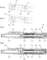
- the injection device 1 comprises a cartridge holder 2, a cartridge 3 and a drive mechanism.
- the drive mechanism comprises an outer housing 4, an inner housing 5, a dose dial sleeve as a dial member 6, a number sleeve as a display member 7, a drive sleeve as a drive member assay 8, a lead screw 9, a bearing 10, a nut 11, a drive spring 12, a return spring 13, a dial grip 14, a dose button 15 and a clutch plate 16. All components are located concentrically about a common principle axis of the mechanism.
- the drive member assay 8 surrounds the lead screw 9, the torsion spring 12 surrounds the drive member 8, the dial member 6 and the inner housing 4 surround the torsion spring 12, the display member 7 surrounds the dial member 6 and the outer housing 4 surrounds the display member 7. Further, the nut 11 and the clutch plate 16 are located between the drive member assay 8 and the dial member 6.
- the drive member assay 8 is depicted comprising two components, which are rigidly fixed together.
- an integrally formed drive member 8 may be provided.
- drive member 8 meaning either an integrally formed or a two-part drive member.
- the dose button 15 is axially constrained to the clutch plate 16. As can be seen in Figure 2 , this may be achieved by a snap-on connection with the clutch plate 16 having an opening for receiving a pin of the dose button 15. Thus, the dose button 15 may be rotatable with respect to the clutch plate 16.
- the dial grip 14 is axially constrained to the outer housing 4 which forms a body for the drive mechanism. Again, as shown in Figure 3 , this may be achieved by a snap-on connection between the dial grip 14 and the outer housing 4.
- the dial grip 14 is rotationally constrained to the clutch plate 16.
- a splined interface is provided between the dial grip 14 and the clutch plate 16. This splined interface is disconnected when the dose button 15 is pressed, i.e. when the dose button 15 and the clutch plate 16 are moved axially relative to the dial grip 14 and the outer housing 4.
- the clutch plate 16 is further rotationally constrained to the dial member 6. Again, a splined interface may be provided between the clutch plate 16 and the dial member 6.
- the clutch plate 16 is further coupled to the drive member 8 via a ratchet interface which occurs on axial abutment.
- the ratchet interface provides a detented position between the dial member 6 and the drive member 8 corresponding to each dose unit and engages different ramped tooth angles during clockwise and anti-clockwise relative rotation between the dial member 6 and the drive member 8.
- This ratchet interface forms the second clutch 19 with corresponding teeth provided on the clutch plate 16 and the drive member 8, respectively.
- the display member 7 is rotationally constrained to the dial member 6. Again, a splined interface may be provided between the display member 7 and the dial member 6. The display member 7 is further constrained to move along a helical path relative to the inner housing 5. This may be achieved by a threaded interface between the display member 7 and the inner housing 5. As an alternative, a threaded interface may be provided between display member 7 and the outer housing 4. The display member 7 is limited to move between a zero dose position (distal position) and a maximum dose position (proximal position) which are defined by end stops, e.g. in the outer housing 4. As shown in Figures 4 to 7 in more detail, the display member 7 has at its distal end a flexible arm 21 which is provided with an abutment feature 22 at its free end.
- the display member 7 is marked with a sequence of numbers which are visible through a window 17 in the outer housing 4.
- a window 17 in the outer housing 4.
- an aperture could be provided in the outer housing 4.
- the window 17 allows the user to denote the dialed dose of medicament.
- the window 17 may be or may comprise a magnifying lens.
- the window 17 may be an integral part of the outer housing 4 or a separate component attached to the housing.
- the nut 11 acts as a last dose nut and is interposed between the dial member 6 and the drive member 8.
- the nut 11 is rotationally constrained to the dial member 6, e.g. via a splined interface.
- the nut 11 may be axially displaced relative to the dial member 6.
- the nut 11 moves along a helical path relative to the drive member 8, e.g. via a threaded interface, when relative rotation occurs between the dial member 6 and the drive member 8, i.e. during dose setting and dose resetting.
- the nut 11 may be splined to the drive member and threaded to the dial member.
- An end stop (not shown) may be provided to limit the movement of the nut 11 in the track defined by the threaded interface.
- the drive member 8 extends from the interface from the dial member 6 down to a splined tooth interface with the inner housing 5. This provides rotational constraint of the drive member 8 to the inner housing 5.
- the releasable splined tooth interface between the drive member 8 and the inner housing 5 forms the first clutch 18 with teeth provided on the dial member 6 and the drive member 8, respectively.
- the dose button 15 When the dose button 15 is pressed, the splined teeth of the first clutch 18 are disengaged and a ratchet feature 20 is engaged which provides an audible and/or tactile feedback during dose dispensing.
- the inner housing 5 is rigidly fixed to the outer housing 4. Thus, neither any rotation nor any axial movement between the inner housing 5 and the outer housing 4 is possible.
- the inner housing 5 and the outer housing 4 may be formed as one integral part, however due to manufacturing reasons it is preferred to provide the housing as the two separate components of the outer housing 4 and the inner housing 5.
- the inner housing 5 is provided with a flexible arm 23 having an abutment feature 24 at its free end.
- the drive spring 12 is a torsion spring which is attached at one end to the inner housing 5 and at the other end to the dial member 6.
- the drive spring 12 is pre-wound upon assembly, such that it applies a torque to the dial member 6 when the mechanism is at zero units dialled.
- the action of rotating the dial grip 14 to set a dose rotates the dial number 6 relative to the inner housing 5 and winds up the drive spring 12.
- the lead screw 9 is rotationally constrained to the drive member 8 e.g. via a splined interface. When rotated, the lead screw 9 is forced to move axially relative to the drive member 8. This is achieved by a threaded interface between the lead screw 9 and the inner housing 5.
- the bearing 10 is axially constrained to the lead screw 9 and acts on the bung within the cartridge 3 during dose dispensing.
- the axial position of the drive member 8, the clutch plate 16 and the dose button 15 is defined by the action of the return spring 13 which abuts the inner housing 5 and applies a force on the drive member 8 in the proximal direction. This ensures that the clutch plate 16 is in splined engagement with the dial grip 14 and that the drive member 8 is in splined engagement with the inner housing 5.
- the return spring 13 also acts to maintain the engagement of the ratchet features between the drive member 8 and the clutch plate 16, i.e. to maintain the engagement of a second clutch 19 [comment: I'm not sure it's a problem but the second clutch has not yet been described at this point.].
- the function of the return spring 13 may be achieved fully or in part by the torsion spring 12.
- the outer housing 4 provides location for the cartridge 3 and the cartridge holder 2 which can be attached to the outer housing 4. Further, the outer housing 4 comprises an interface to rigidly constrain the inner housing 5 and a groove on its external surface to axially retain the dial grip 14. Further, a removable cap may be provided which fits over the cartridge holder 2 and is retained via clip features.
- Figures 2 and 3 and Figures 4 and 5 show the drive mechanism during dose setting and dose dispensing, respectively.
- the dose button 15 when the dose button 15 is depressed and the drive member 8 moves axially, it acts on the flexible arm 23 on the inner housing 5 moving it radially outwards.
- the arm 23 and its abutment feature 24 are in a radially inner position and are pushed outwards to a radially outer position during dose dispensing.
- the distal end of the drive member 8 may comprise a tapered or flared portion as shown in the Figures.
- the radially inner position of abutment feature 24 is chosen such that the abutment feature 22 of the display member 7 does not contact abutment feature 24 irrespective of the position of the display member 7.
- Figures 6 and 7 show approaching the end of a dose during dose dispensing.
- the flexible click arm 21 with its abutment feature 22 rides over the inner housing flexible arm 23 and its abutment feature 24, creating an audible click.
- the inner housing flexible arm 23 is only moved outwards during dispense, the setting torque is not affected and no click is created when dialling down to zero units during dose resetting.
- FIG. 2 shows the drive mechanism in an at rest condition which is a condition if a user does not exert any forces on the drive mechanism.
- the first clutch 18 couples the drive member 8 to the inner housing 5 and the second clutch 19 allows a relative rotation between the clutch plate 16 and the drive member 8.
- a torque has to be provided to overcome the resistance of the ratchet feature, i.e. the clutch plate 6 is not freely rotatable with respect to the drive member 8.
- the second condition which is shown in Figure 3 occurs if a user depresses dose button 15. This decouples the first clutch 18 such that the drive member 8 is free to rotate with respect to the inner housing 5 and the second clutch 19 is coupled to prevent a relative rotation between the drive member 8 and the clutch plate 16.
- the display member 7 With the device in the at rest condition, the display member 7 is positioned against its zero dose abutment with the inner housing 5 and the dose button 15 is not depressed. A dose marking "0" on the dial member 7 is visible through the window 17 on the outer housing 4.
- the drive spring 12 which has a number of pre-wound turns applied to it during assembly of the device applies a torque to the dial member 6.
- the dial member 6 is prevented from rotating under the action of the torque by its ratchet interface (second clutch 19) with the drive member 8.
- the drive member 8 is prevented from rotating by the interlock provided by the engagement of splined teeth on the drive member 8 and the inner housing 5 (first clutch 18).
- Return spring 13 maintains the first clutch 18 in its coupled state by pushing the drive member 8 in the proximal direction.
- the drive member 8 is free to be displaced in the distal direction against the force of the return spring 13 as the teeth of the second clutch 19 override each other upon a relative rotation between the drive member 8 and the clutch plate 16.
- the height of the teeth of the second clutch 19 is smaller than the axial height of the splines of the first clutch 18.
- the first clutch 18 remains in its coupled state even if the teeth of the second clutch 19 override each other.
- the user selects a variable dose of medicament by rotating the dial grip 14 clockwise which generates an identical rotation in the dial member 6.
- Rotation of the dial member 6 causes wind up of the drive spring 12, increasing the energy stored within it.
- the drive member 8 is still prevented from rotating due to the engagement of its splined teeth with the inner housing 5 (first clutch 18 coupled). A relative rotation must therefore occur between the clutch plate 16 and the drive member 8 via the ratchet interface of the second clutch 19.
- the user torque required to rotate the dial grip 14 is a sum of the torque required to wind up the drive spring 12 and the torque required to overhaul the ratchet feature of the second clutch 19.
- the return spring 13 is designed to provide an axial force to the ratchet feature and to bias the components (drive member 8, clutch plate 16, dose button 15) away from the cartridge end of the injection device 1.
- the axial load acts to maintain engagement of the ratchet teeth of the clutch plate 16 and the drive member 8.
- the torque required to overhaul the ratchet teeth is resultant from the axial load applied by the return spring 13, the clockwise ramp angle of the ratchet, the friction coefficient between the mating surfaces and the mean radius of the ratchet features.
- the dial member 6 rotates relative to the drive member 8 by one set of ratchet teeth. At this point the ratchet teeth reengage into the next detented position. An audible click is generated by the ratchet reengagement, and tactile feedback is given by the change in torque input required.
- the second clutch 19 forms a ratchet clicker.
- Relative rotation of the dial member 6 and the drive member 8 causes a last dose nut 11 to travel along its threaded path towards its last dose abutment on the dial member 6.
- Rotation of the dial member 6 further generates rotation in the display member 7, which travels along its helical path defined by its interface with the inner housing 5.
- the dose marking corresponding to x units become aligned to the window 17 in the outer housing 4.
- the device is now set to deliver x units of liquid medicament.
- the dial member 6 With no user torque applied to the dial grip 14, the dial member 6 is now prevented from rotating under the action of the torque applied by the drive spring 12, solely by the ratchet engagement between the clutch plate 16 and the drive member 8 (second clutch 19).
- the torque necessary to overhaul the ratchet in the anti-clockwise direction is resultant from the axial load applied by the return spring 13, the anti-clockwise ramp angle of the ratchet, the friction coefficient between the mating surfaces and the mean radius of the ratchet features.
- the torque necessary to overhaul the ratchet must be greater than the torque applied to the dial member 6 (and hence clutch plate 16) by the drive spring 12.
- the ratchet ramp angle is therefore increased in the anti-clockwise direction to ensure this is the case.
- the user may now choose to increase the selected dose by continuing to rotate the dial grip 14 in the clockwise direction.
- the process of overhauling the ratchet interfaces between the dial member 6 and the drive member 8 is repeated for each dose unit. Additional energy is stored within the drive spring 12 for each dose unit and audible and tactile feedback is provided for each unit dialed by the reengagement of the ratchet teeth.
- the torque required to rotate the dial grip 14 increases as the torque required to wind up the drive spring 12 increases.
- the torque required to overhaul the ratchet in the anti-clockwise direction must therefore be greater than the torque applied to the dial member 6 by the drive spring 12 when the maximum dose has been reached.
- the display member 7 engages with its maximum dose abutment on the outer housing 4, which prevents further rotation of the display member 7, dial member 6, clutch plate 16 and dial grip 14. At this point the maximum dose marking on the display member 7 is aligned to the window 17 in the outer housing 4.
- the last dose nut 11 may contact its last dose abutment, i.e. the end stop with the dial member 6.
- the abutment prevents further relative rotation of the dial member 6 and the drive member 8 and therefore limits the dose that can be selected.
- the position of the last dose nut 11 is determined by the total number of relative rotations between the dial member 6 and the drive member 8, which have occurred each time the user sets a dose.
- the user With the mechanism in a state in which a dose has been selected, the user is able to deselect or reset any number of units from this dose. Deselecting a dose is achieved by the user rotating the dial grip 14 anti-clockwise.
- the torque applied to the dial grip 14 by the user is sufficient, when combined with the torque applied by the drive spring 12 to overhaul the ratchet 19 between the clutch plate 16 and the drive member 8 in the anti-clockwise direction.
- anti-clockwise direction occurs in the dial member 6 (via the clutch plate 16) which returns the display member 7 towards the zero dose position, and unwinds the drive spring 12.
- the relative rotation between the dial member 6 and the drive member 8 causes the last dose nut 11 to return along its helical path, away from the last dose abutment.
- the user With the mechanism in a state in which a dose has been selected, the user is able to activate the drive mechanism to commence delivery of a dose (dose dispensing). Delivery of a dose is initiated by the user depressing the dose button 15 on the top (proximal end) of the drive mechanism. When the dose button is depressed, it moves axially, acting on the clutch plate 16, which in turn acts on the drive member 8. The clutch plate 16 disengages its spline teeth from the dial grip 14 and after that the drive member 8 disengages its spline teeth (first clutch 18) from the inner housing 5.
- the ratchet feature 20 of the inner housing 5 comprises a clicker arm (not shown).
- the clicker arm is a compliant cantilever beam integrated into the inner housing 5, which interfaces radially with the spline ratchet teeth in the drive member 8.
- the ratchet teeth 18b spacing corresponds to the drive member 8 rotation required to deliver a single dose unit.
- the torque required to overhaul the clicker arm is resultant from the ratchet teeth profile, the stiffness of the cantilever beam and the nominal interference between the clicker arm and the ratchet.
- the clicker arm interface is designed such that the torque required to overhaul is significantly less than the torque provided by the drive spring 12.
- the rotation of the dial member 6 also causes the display member 7 to return along its helical path, relative to the inner housing 5, towards the zero dose abutment. Delivery of a dose continues via the mechanical interactions described above while the user continues to depress the dose button 15. If the user releases the dose button 15, the return spring 13 returns the dose button 15 to its at rest position via the drive member 8 and the clutch plate 16 such that the drive member 8 becomes rotationally constrained and delivery of a dose is halted.
- the user may release the dose button 15 which will reengage the first clutch 18 between the inner housing 5 and the drive member 8. The mechanism is now returned to the at rest condition.
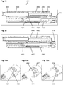
- FIG. 8 A second embodiment of a drive mechanism which is suitable for an injection device 101 is shown in Figures 8 to 11 .
- the injection device 101 comprises a cartridge holder 102, a cartridge 103 containing a medicament, optionally a cap (not shown) and a drive mechanism.
- the drive mechanism comprises an outer housing 104 with a window 117, an inner housing 105, a dial member 106 (dial sleeve), a display member 107 (number sleeve), a drive member 108 (drive sleeve), a lead screw 109, a bearing 110, a nut 111, a torsion spring 112, a dial grip 114, a first clutch 118, a second clutch 119 (clutch plate), a ratchet feature 120, a clutch spring 125, a trigger clutch 126, a trigger 127 and a trigger cover 128.
- all components, except for the trigger 127 and the trigger cover 128, are located concentrically about a common principal axis of the drive mechanism.
- the dial grip 114 is axially constrained to the outer housing 104. It is rotationally constrained, via a splined interface, to the dial member 106. As shown in Figure 11 , the dial member 106 is coupled to the drive member 108 via a ratchet interface (second clutch 119), which occurs on an axial abutment.
- the ratchet provides a detented position between the dial member 106 and the drive member 108 corresponding to each dose unit, and engages different ramped tooth angles during clockwise and anti-clockwise relative rotation. Corresponding ratchet teeth are provided on facing surfaces of the dial member 106 and the drive member 108.
- the display member 107 is rotationally constrained, via a splined interface, to the dial member 106. It is constrained to move along a helical path, relative to the inner housing 105, via a threaded interface.
- the display member 107 is marked with a sequence of numbers, which are visible through the window 117 in the outer housing 104, to denote the dialled dose of medicament.
- the last dose nut 111 is located between the dial member 106 and the drive member 108. It is rotationally constrained to the dial member 106, via a splined interface. It moves along a helical path relative to the drive member 108, via a threaded interface, when relative rotation occurs between the dial member 106 and drive member 108.
- the drive member 108 extends from the interface with the dial member 106 down to a ratchet interface with the inner housing 105, which occurs on an axial abutment.
- the ratchet interface defines the axial position of the drive member 108 at the end of dose delivery, and is included to improve dose accuracy.
- the drive member 108 is rotationally constrained to the housing via engagement of a set of spline teeth, when the trigger 127 is activated. It provides a clicker arm, which acts radially against a set of ratchet teeth in the inner housing 105. It moves along a helical path relative to the lead screw 109, via a threaded interface.
- the drive member 108 provides an axial abutment with the inner housing 105, which engages when the drive mechanism dispenses, to react the force applied by the lead screw 109 to the cartridge 103.
- the torsion spring 112 is attached at one end to the inner housing 105 and at the other end to the dial member 106.
- the attachments at both ends are configured to transfer tangential forces, resulting from torsion of the spring 112, and axial forces along the primary axis of the drive mechanism (longitudinal axis).
- the torsion spring 112 is pre-wound upon assembly, such that it applies a torque to the dial member 106 when the mechanism is at zero units dialled.
- the action of rotating the dial grip 114, to set a dose rotates the dial grip 114 relative to the inner housing 105, and winds up the torsion spring 112.
- the torsion spring 112 is designed in such a way as to exert an axial force which acts to pull the dial member 106 towards the inner housing 105.
- the lead screw 109 is rotationally constrained to the inner housing 105 via a splined interface.
- the lead screw 109 is forced to move axially relative to the inner housing 105, through its threaded interface to the drive member 108, when the drive member 108 moves relative to the inner housing 105.
- the bearing 110 (washer) is axially constrained to the lead screw 109 and acts on the bung within the liquid medicament cartridge 103.
- the inner housing 105 is rigidly constrained to the outer housing 104.
- the axial abutment with the drive member 108 is provided by a pair of compliant arms which deflect during assembly.
- a pair of abutment features is provided at either end of the threaded interface with the display member 107, which limit the range of travel of the display member 107. These abutments provide the zero dose and maximum dose stops.
- the inner housing 105 provides a rotational constraint to the trigger clutch 126, and provides an axial abutment which reacts the axial force generated by the clutch spring 125.
- the axial position of the trigger clutch 126 is defined by the action of the clutch spring 125, which forces the trigger clutch 126 towards the cartridge end (distal end) of the drive mechanism, and its abutment with the trigger 127.
- the trigger clutch 126 engages with the spline teeth on the drive member 108 which constrains the rotation of the drive member 108.
- the spline teeth on the trigger clutch 126 and the corresponding spline teeth on the drive member 108 form the first clutch 118. Engagement and disengagement of the first clutch 118 is shown in Figures 8 and 9 .
- the clutch spring 125 is located between the inner housing 105 and the trigger clutch 126 and acts to force the trigger clutch 126 towards the cartridge end of the drive mechanism.
- the trigger 127 is constrained to pivot in the outer housing 104. It has an integral spring element, which acts to rotate the trigger 127 away from the outer housing 104. When the trigger 127 is depressed, an abutment is created with the trigger clutch 126, which moves the trigger clutch 126 axially towards the inner housing 105.
- the outer housing 104 provides location for the liquid medication cartridge 103, the pivot for the trigger 127, an interface to rigidly constrain the inner housing 105, a window 117 through which the dose number on the display member 107 can be viewed, and a groove on its external surface to axially retain the dial grip 114.
- the trigger cover 128 may clip into the outer housing 104, and retains the trigger 127 within its pivot interface with the outer housing 104.
- the removable cap fits over the cartridge holder element 102 and is retained onto the outer housing 104 via clips when the drive mechanism is not in use. When the cap is fitted onto the outer housing 104, a mechanical interlock is created with the trigger 127, which prevents the trigger 127 from being depressed from its at rest position.
- display member 107 is provided with a flexible arm 121 on its distal end having an abutment feature 122. Further, the trigger clutch 126 is provided with a corresponding abutment feature 124.
- the display member 107 With the device in the at rest condition, the display member 107 is positioned against its zero dose abutment with the inner housing 105 and the trigger 127 is not depressed. Dose marking '0' on the display member 107 is visible through the window 117 on the outer housing 104. As shown in Figures 8 and 10 , the trigger clutch 126 is in a distal position, which is the position for dose setting and dose resetting.
- the dial member 106 rotates relative to the drive member 108. Rotation of the dial member 106 generates rotation in the display member 107, which travels along its helical path defined by its interface with the inner housing 105.
- the device is now set to deliver liquid medicament.
- the user may now choose to increase the selected dose by continuing to rotate the dial grip 114 in the clockwise direction.
- the drive mechanism With the drive mechanism in a state in which a dose has been selected, the user is able to deselect any number of units from this dose. Deselecting a dose is achieved by the user rotating the dial grip 114 anti-clockwise, which returns the display member 107 towards the zero dose position.
- abutment features 122, 124 do not contact each other during dose resetting because abutment feature 124 is distally moved out of the track of display member 107 and its abutment feature 122.
- the user With the mechanism in a state in which a dose has been selected, the user is able to activate the drive mechanism to commence delivery of a dose. Delivery of a dose is initiated by the user depressing the trigger 127 on the side of the drive mechanism. As the trigger is depressed, an abutment is created with the trigger clutch 126 which acts to move the trigger clutch axially away from the cartridge 103, i.e. in the proximal direction, against the action of the clutch spring 125. When the trigger 127 is fully depressed, sufficient axial travel has occurred in the trigger clutch 126 to move abutment feature 124 into the path of abutment feature 122 of the display member 107.
- the free end of click-arm 121 rides up a ramp on the abutment feature 124. At the zero position, the click-arm 121 overrides the ramp and returns to its original position providing a tactile and an audible feedback to the user. Thus, the end of dose click features are only engaged during dispensing.
- the injection device 201 comprises a cartridge 203, a housing 204 and a chassis 205 (inner housing body).
- a dial gear 206 (dial member) is splined to a number wheel 207 and translated axially by a button 215. Further, the dial gear 206 is splined to a release gear 208 (drive member) during dose dispensing.
- the number wheel 207 is a display member which displays numbers.
- a prism 217 is provided which magnifies and reflects the numbers displayed on the number wheel 207.
- a last dose nut 211 is splined to the dial gear 206 and threaded to the release gear 208.
- a belt is retained in a belt drum and a ferrule and passes over a roller in the chassis 205.
- a compression spring 212 is provided as a prestressed drive spring acting on a piston rod 209. The spring 212 is fitted between chassis 205 and the ferrule.
- the release gear 208 is geared to the belt drum and retained in the chassis 205 during dose setting, whereas it is splined to the dial gear 206 during dose dispensing.
- a dial 214 which is rotationally coupled to the dial gear via face teeth is rotated clockwise to set a dose. Detents between the dial 214 and a front casework provide discrete dose set positions.
- the release gear 208 is rotationally fixed by the chassis 205.
- the number wheel 207 is driven directly from the dial gear 206 with zero dose and maximum dose stops provided between the number wheel and the chassis.
- the last dose nut 211 is rotated by the dial gear 206 up the thread on the release gear towards a last dose stop. In the similar way, a set dose may be decreased by rotating the dial anti-clockwise.
- the button 215 is depressed, locking the dial 214.
- the dial gear 206 engages with the release gear 208 and pushes locking arms of the chassis 205 out of engagement from the release gear 208, allowing this to rotate under the action of the spring 212.
- Rotation of the release gear 208 allows the belt drum to rotate, releasing the belt and allowing the spring 212 to act on and advance the cartridge bung.
- a ramp feature 222 on the dial gear 206 engages with a clicker arm 223 on the chassis to provide an end of dose click.
- these features are not engaged, so the 'drop' at the end of dose can be very severe. This is shown as partial section through the chassis 205 and the dial gear 206 in Figures 14 and 15 .
- the clicker arm 223 drops off a steep angle ramp and thus creates distinct click sound against dial gear 206.
- Main components of the injection device 301 are a cartridge 303, an outer housing 304, an inner housing body 305, a drive sleeve 308 (drive member), a dial sleeve 306 (dial member), a piston rod in the form of a lead screw 309, a dose dial grip 314 and a spring 312, which is a flat spring or tensioning element.
- the spring 312 is provided on two spools between the inner body 305 and the drive sleeve 308.
- the drive sleeve 308 is rotationally fixed by the inner body 305 during dose setting and dose resetting.
- the lead screw 309 is splined to the drive sleeve 308 and threaded to the inner body 305.
- the dial sleeve 306 is coupled to the drive sleeve 308 via a detent and clutched connection.
- the dose dial grip 314 is splined to the dial sleeve 306 during dose setting and dose resetting.
- a last dose nut 311 is splined to the dial sleeve 306 and threaded to the drive sleeve 308.
- the dose dial grip 314 is rotated clockwise by the user. This causes the dial sleeve 306 to rotate, moving a dose nut 307 away from its zero dose stop feature and increasing the dose displayed.
- the dose counter consists of the dial sleeve 306 with printed units and a tens wheel which is incremented by the action of an index gear once per revolution.
- the last dose nut 311 rotates on a thread on the drive sleeve 308 towards the last dose stop.
- the drive sleeve 308 is locked by its splined engagement with the housing 304, thus preventing it from being rotated by the spring 312.
- the dose dial grip 314 is depressed. This disengages the dose dial grip 314 from the dial sleeve 306 so that it does not rotate during dispense.
- the drive sleeve 308 is moved axially with the dose dial grip 314, disengaging the splined engagement with the inner body 305 allowing the spring 312 to rotate drive sleeve 308.
- the drive sleeve 308 winds the lead screw 309 forwards through the thread in the inner body 305 to advance the cartridge bung.
- the odometer counter mechanism and the dose nut 307 then return towards their zero dose positions.
- a spring arm 321 with an abutment feature is provided on the dose nut 307.
- the spring arm 321 rides over a zero unit stop feature on the dial sleeve and is deflected radially outwards as the dial sleeve 306 rotates anti-clockwise towards the zero dose position.
- the zero unit stop passes the end of the spring arm 321
- the stored energy is released moving the spring arm 321 inwards radially causing a click as it hits the dial sleeve 306.
- dialling up from 0 to 1 unit the spring arm 321 is forced axially by a ramp on the dial sleeve 306 and back into its unstressed position. This will not create any audible feedback.
- FIG. 19 An alternative embodiment is shown in Figures 19 and 20 , wherein the main function and components are as described above with respect to the fourth embodiment.
- a spring arm 323 on dial sleeve 306 is deflected axially by a ramp feature on the dose nut 307.
- the ramp feature passes the end of the spring arm 323, the stored energy is released, moving the spring arm 323 axially causing a click as it hits the dose nut 307 thread form.
- the spring arm 323 is forced axially by the opposite side of the ramp feature on the dose nut and falls off the edge, but does not contact a surface to cause a click.
- the dose nut 307 traverses away from the spring arm 323 and so they do not come into contact again.
- FIG. 21 to 23 A third embodiment of the invention is depicted in Figures 21 to 23 , wherein the main function and components are as described above with respect to the second embodiment not encompassed by the claims.
- Main components of the injection device 401 are a cartridge 403, an outer housing 404, an inner housing body 405, a drive sleeve 408 (drive member), a dial sleeve 406 (dial member), a piston rod in the form of a lead screw 409, a dose dial grip 414 and a spring 412, which is a flat spring or tensioning element.
- the lead screw 409 is arranged spaced from and parallel to the drive sleeve 408 and the dial sleeve 406.
- a drive tube 430, which is geared to the drive sleeve 408 is provided as a driven member which is splined to the lead screw 409.
- a clicker 431, which is splined to the housing 404 and detented to the dial grip 414 is provided coaxially with the drive sleeve 408.
- the dial sleeve 406 is splined to a number sleeve 407 and is further splined to the dial grip 414 during dose setting and dose resetting.
- the dial grip 414 is rotated to set the dose.
- the dial grip 414 rotates the dial sleeve 406, which in turn rotates the number sleeve 407, causing it to move away from its zero units stop and display the desired dose through a window in the housing 404.
- the drive sleeve 408 is restrained during dose setting via a splined interface to the housing 404.
- the spring 412 applies a permanent torque to it. Tactile and audible feedback is provided by the interaction of the dial grip 414 and the clicker 431.
- the clicker 431 is splined to the housing 404 and shuttles axially under the action of a trigger spring as each dose increment is dialled.
- the dial grip 414 upper end is pressed by the user.
- the dial grip 414 first disengages from the dial sleeve 406 so that it does not rotate during dispense. This causes the drive sleeve 408 to be displaced towards the distal end of the device.
- the drive sleeve 408 then engages with splines on dial sleeve 406.
- the drive sleeve 408 then disengages from the housing 404, allowing it to be rotated by the spring 412.
- the drive sleeve 408 rotates the drive tube 430, which in turn rotates the lead screw 409, causing it to advance axially through a thread in the housing 404 and displace the bung in the cartridge.
- the clicker 431 moves between two distinct axial positions for dose setting or resetting and dose dispensing. This allows a compliant feature 424 on the clicker 431 to interact with a feature 422 on the number sleeve 407 during dispensing but not during dialling so that the dial torque is not affected.
Description
- The present invention relates to a drive mechanism, which is suitable for an injection device, especially a pen type drug delivery device. The mechanism comprises a housing and a dosing member, which during dose setting, dose resetting and dose dispensing rotates relative to the housing between a zero dose position and a maximum dose position, an insert which is rotationally constrained to the housing, wherein the dosing member and the insert each comprise at least one abutment feature contacting each other when the dosing member reaches its zero dose position during dose dispensing, and wherein an audible and/or tactile feedback is generated by the contact of the abutment features. Further, the present invention relates to an injection device comprising such a drive mechanism and a cartridge containing a medicament.
- In the following, the distal end of an injection device or drive mechanism is referred to as the end where a cartridge and e.g. a needle are located, whereas the opposite end is the proximal end. A dose button may be provided at the proximal end.
- The general function of a drive mechanism as defined above is to set a dose and to subsequently dispense the set dose. Dose setting (dose dialling) usually requires a user to manipulate one element of the drive mechanism, preferably to rotate a dial member e.g. via a dial grip. During dose dispensing the dial member may move, e.g. rotate, back to its original position wherein a drive member, which is not actuated during dose setting is moved together with the dial member during dose dispensing. The movement of the drive member may be a rotation, a displacement in the distal direction or a combined movement e.g. along a helical path. The drive member may act on a piston rod, e.g. a lead screw, for expelling medicament from a cartridge during dose dispensing.
- In addition to this basic function of a drive mechanism it is in some cases preferred to allow a resetting of an already set dose, i.e. a correction or a deselecting of a dose. Preferably the user simply has to rotate the dial member, e.g. via a dial grip, in the opposite direction compared to the rotation during dose setting. Preferably, the drive member is not actuated during dose resetting, either.
- At the beginning of dose setting, the mechanism is usually in a zero dose position, i.e. the previous dose has been fully administered and no new dose has been dialed. The user may set a dose up to a maximum dose which is defined by the mechanism, for example by providing an end stop which prevents setting of a higher dose. Typically, a maximum settable dose is 60, 80, 100 or 120 units of a medicament. During dose resetting, an already set dose may be reduced down to the zero dose position of the device. It is important that a user fully dispenses the required set dose to avoid an underdose which may have serious medical consequences. Thus, it is required to indicate to a user that the mechanism is in its zero dose position after dose dispensing.
- An injection device as defined above is known e.g. from
EP 1 974 761 B1 - In addition, a drive mechanism is known from
EP 0 730 876 B1 which includes a housing and a dial. The dial is rotated during dose setting and axially displaced during dose dispensing. As the dial reaches its end of dose position (zero dose position), a finger of the dial moves past a housing edge and into a housing groove, which creates a click sound thereby providing an audible confirmation that the entire dosage has been injected. Further,WO 2006/079481 A1 discloses a similar mechanism, which provides a non-visual feedback signal to a user only at the end of injection of a set dose. This is achieved by providing two parts which perform a relative rotational movement during injection of a dose, wherein the two parts abut or engage thus causing the non-visual feedback signal. In some embodiments ofWO 2006/079481 A1 , the two parts may perform a relative rotation during dose setting, too. A relative rotation during dose resetting is not described. The mechanisms ofEP 0 730 876 B1 andWO 2006/079481 A1 do not prevent that the click sound or non-visual feedback signal is generated during dose resetting. Thus, users may be confused if a signal is provided which indicates completion of the dose dispensing process even if the user did not initiate this dispensing process. - A device with another end of dose feedback is known from
WO 2006/084876 A1 . This is generated by interaction of an end surface on an inner housing and the internal thread of a scale drum. A resilient member is used to lift the scale after dose dispensing to allow the thread to pass the end surface for setting a new dose. - Further,
WO 2011/060785 A1 discloses a scale with an end-of-dose ratchet arm. The scale rotates during dose setting, dose correction and dose dispensing. The housing comprises a stop rib which the ratchet arm passes just before the injection stops. This creates a clicking sound different from the sound of injection clicks. Further, scale is axially movable against the bias of flexible arms when the actuation button is pressed. The flexible arms displace the scale back after dose dispensing. This results in the end-of-dose ratchet arm not interfering with the stop rib during dose setting, i.e. when the actuation button is not depressed. A similar mechanism is known fromWO 2011/060786 A1 disclosing a dispense clicker mechanism having a series of teeth on an inner side of the housing with one tooth having a different configuration. A ratchet arm is held in a position not interfering with the teeth during dose setting or dose correction and is moved axially to a position engaging teeth during dispensing. Tooth is located such that a different click is generated at the end of injection. - It is an object of the present invention to provide an improved alternative to the above solutions. Especially, it is an object of the present invention to provide a drive mechanism and an injection device giving a reliable feedback to users at the end of the dispensing process. Preferably, the mechanism does not generate a signal during dose resetting.
- This object is solved by a drive mechanism with the features of
claim 1. According to the present invention, the mechanism further comprises an insert which is rotationally constrained to the housing. The dosing member and the insert each comprise at least one abutment feature which contact each other in the moment when the dosing member reaches its zero dose position during dose dispensing. This contact of the abutment features generates an audible and/or tactile feedback. In other words, the mechanism provides a tactile and/or audible signal to the user indicating that the mechanism reached its zero dose position at the end of the dose dispensing process. This tactile and/or audible signal may also be detected by visually impaired users. It is preferred if the abutment features contact each other only during dose dispensing, i.e. not during dose resetting, when the dosing member reaches its zero dose position. This avoids confusion for the users. Providing one of the abutment features on an insert may have the benefit of generating a feedback which is distinct from a feedback generated by the housing, e.g. during dose setting and/or dose resetting and/or dose dispensing. The drive mechanism further comprises an additional component part. which is axially movable between a dose dispensing position and a dose setting and resetting position wherein the abutment features contact each other only when the additional component part is in its dose dispensing position. For example, the additional component part radially deflects one of the abutment features when the additional component part is in its dose dispensing position. In other words, the axial movement of the additional component part switches the mechanism between a mode in which reaching the zero dose position at the end of the dose dispensing process is indicated by a feedback signal and a mode in which reaching the zero dose position is not indicated by such a feedback, e.g. during dose resetting (dose correcting). - According to a first embodiment of the invention, the drive mechanism comprises an inner body rotationally constrained to the housing and a number sleeve which is in threaded engagement with the housing or the inner body. The number sleeve is movable between a zero dose position and a maximum dose position. The inner body comprises a flexible arm having a first abutment feature and the number sleeve comprises a corresponding second abutment feature contacting the first abutment feature when the number sleeve reaches its zero dose position during dose dispensing. Preferably, the number sleeve is a tubular component having a scale or numbers to visually indicate a set dose. The number sleeve may be directly actuated by a user or indirectly, e.g. via a dose dial grip and/or a dose setting member which is at least rotationally coupled to the number sleeve.
- For the above mentioned first embodiment and all of the embodiments described below the abutment features (e.g. ramp features) and flexible arm features may be swapped between the two interacting components. For example, in an alternative to the first embodiment, the number sleeve may have the flexible arm with the first abutment feature and the inner body may have the second abutment feature.
- According to a second embodiment of the invention, the drive mechanism comprises a trigger clutch rotationally constrained to the housing and a number sleeve which is in threaded engagement with the housing or an inner body. The number sleeve is movable between a zero dose position and a maximum dose position. The trigger clutch comprises a first abutment feature and the number sleeve comprises a corresponding second abutment feature contacting the first abutment feature when the number sleeve reaches its zero dose position during dose dispensing. The trigger clutch may be a component which is actuated by a trigger which is pressed or actuated to initiate dose dispensing. The trigger clutch may have the additional function of coupling and/or decoupling further components of the mechanism, e.g. a drive member and the housing or an inner housing body.
- To ensure that in the two above embodiments the abutment features contact each other only during dose dispensing the number sleeve and its second abutment feature move on a helical path during dose setting, dose resetting and dose dispensing wherein the first abutment feature is in the helical path only during dose dispensing. This avoids unintended generation of a signal during dose resetting.
- For the first embodiment this may be achieved by providing a drive member which is axially displaceable relative to the housing between a dose setting position and a dose dispensing position. Preferably, the first abutment feature is not in the helical path in an unstressed state of the flexible arm wherein in its dose dispensing position the drive member urges the flexible arm and its first abutment feature into the helical path. In other words as long as the drive member is not moved into its dose dispensing position, no signal could be generated because the abutment features do not contact each other even in the zero dose position of the mechanism. Only during dose dispensing, the mechanism is in a condition that allows contact of the abutment features and thus generation of the signal.
- For the second embodiment this may be achieved in a similar manner by providing a trigger for axially displacing the trigger clutch relative to the housing between a dose setting position and a dose dispensing position, wherein the first abutment feature is not in the helical path in the dose setting position of the trigger clutch and wherein the trigger urges the trigger clutch and its first abutment feature in its dose dispensing position into the helical path.
- As an alternative or in addition to the movement of the first abutment feature, the second abutment feature may be moved between a dose setting or dose resetting position and a dose dispensing position.
- In the first and second embodiment, the mechanism may further comprise a torsion spring fixed between the housing and a dial member such that energy is accumulated in the torsion spring upon rotation of the dial member relative to the housing during dose setting, which energy is used to actuate a drive member during dose dispensing.
- According to an embodiment not encompassed by the claims, the drive mechanism comprises a chassis rotationally constrained to the housing and a dial gear which is rotatable relative to the chassis between a zero dose position and a maximum dose position and which is axially displaceable relative to the chassis between a dose setting position and a dose dispensing position. Preferably the chassis comprises a first abutment feature and the dial gear comprises a corresponding second abutment feature contacting the first abutment feature when the dial gear reaches its zero dose position during dose dispensing. The dial gear may have the form of a ring or disk and may be provided with splines and/or teeth engaging further components of the mechanism. Further, the axial displacement of the dial gear, i.e. a displacement in the direction of the axis of rotation of the dial gear during dose setting, may couple and/or de-couple the dial gear to/from further components.
- Preferably, the first abutment feature is a flexible finger provided on the chassis and the second abutment feature is a recess or a ramp on the dial gear. The flexible finger does not contact the recess or ramp in the dose setting position of the dial gear whereas the flexible finger contacts the recess or ramp in the dose dispensing position when the dial gear reaches its zero dose position. Thus, contact of the abutment features is prevented as long as the dial gear is in its dose setting position.
- The mechanism may further comprise a compression spring acting on a piston rod or bung in a cartridge during dose dispensing. The spring may be coupled to a cable or belt which may initially be wound on a spool and which is unwound thus releasing the spring during dose dispensing. The spring may be pre-compressed during the manufacturing process such that the energy for dispensing the contents of the whole cartridge of medicament is stored in the spring.
- According to a further embodiment not encompassed by the claims, the drive mechanism comprises a dose nut, which is axially displaceable between a zero dose position and a maximum dose position and which is rotationally constrained to the housing. The mechanism further comprises a dial sleeve which is rotatable relative to the housing. The dose nut may comprise a flexible finger with a first abutment feature, which is deflected during dose dispensing and which hits a second abutment feature provided on the dial sleeve when the dose nut reaches its zero dose position.
- According to another embodiment not encompassed by the claims, the drive mechanism comprises a dose nut, which is axially displaceable between a zero dose position and a maximum dose position and which is rotationally constrained to the housing, and a dial sleeve which is rotatable relative to the housing, wherein the dial sleeve comprises a flexible finger with a first abutment feature, which is deflected during dose dispensing and which hits a second abutment feature provided on the dose nut when the dose nut reaches its zero dose position.
- Preferably, the dose nut of those embodiments is a full nut or a half nut threadedly engaged with the dial sleeve. The dose nut may be splined to the housing to allow an axial displacement of the dose nut relative to the housing but preventing a relative rotational movement. The axial displacement of the dose nut may be limited by two stops, which might be the ends of the helical track or separate stop elements, defining the zero dose position and the maximum dose position. Preferably, the dial sleeve rotates during dose setting, dose resetting and dose dispensing such that the dose nut due to the threaded interface with the dial sleeve travels in the helical path of the threaded interface. Further rotation of the dial sleeve is limited by the dose nut abutting one of the two stops in the zero dose position and the maximum dose position. In other words, the zero dose position and the maximum dose position of the dial sleeve is defined by the number of rotations allowed by position of dose nut in helical track of dial sleeve.
- According to a third embodiment of the invention, the drive mechanism comprises a clicker rotationally constrained to the housing and a number sleeve which is in threaded engagement with the housing or an inner body and movable between a zero dose position and a maximum dose position. The clicker comprises a first abutment feature and the number sleeve comprises a corresponding second abutment feature contacting the first abutment feature when the number sleeve reaches its zero dose position during dose dispensing.
- Preferably, the number sleeve and its second abutment feature move on a helical path during dose setting, dose resetting and dose dispensing whereas the clicker is axially displaceable relative to the housing such that the first abutment feature is in the helical path only during dose dispensing. Thus, only during dose dispensing, the mechanism is in a condition that allows contact of the abutment features and hence generation of the signal. The clicker may be an element which causes together with a further component, e.g. an inner body, the number sleeve, a dial member or the like, a click sound during dose setting and/or dose resetting. For this purpose, the clicker may be provided with splines, notches or teeth which override corresponding features of the further component. During dose setting and/or dose resetting, the clicker may shuttle axially as the splines, notches or teeth override the corresponding features.
- According to one aspect of this embodiment, the drive mechanism further comprises a dial grip sleeve which is axially displaceable relative to the housing between a dose setting position and a dose dispensing position. The first abutment feature is not in the helical path in the dose setting position of the dial grip sleeve whereas in its dose dispensing position the dial grip sleeve axially displaces the clicker to urge its first abutment feature into the helical path.
- According to a further aspect of this embodiment, a cartridge and a piston rod acting on a bung in the cartridge may be provided parallel and spaced from the clicker and the number sleeve. A meshing gear interface may be provided for transmitting torque between a driven member on the cartridge side and a drive member on the number sleeve side.
- The mechanism of the third embodiment may further comprise a flat spring or tensioning element acting on a drive member during dose dispensing. The flat spring or tensioning element may initially be wound on a spool and which is unwound onto a second spool thus releasing the flat spring or tensioning element during dose dispensing. The flat spring or tensioning element may be pre-wound during the manufacturing process such that the energy for dispensing the contents of the whole cartridge of medicament is stored in the flat spring or tensioning element.
- To allow rotation of components of the mechanisms according to the above embodiments, it is preferred if the components are mainly located concentrically about a common longitudinal axis of the drive mechanism. Thus, the components may have a tubular or sleeve-like shape. For example, the nut, the drive member and the dial may each be a tubular element with the nut surrounding the drive member and the dial member surrounding the nut (and thus the drive member). As an alternative, the nut may be designed as a half-nut, i.e. a ring segment.
- Further, although it is desirable to reduce the total number of components of a drive mechanism, it might be useful for manufacturing reasons to split one or more components into separate elements. For example, a housing may comprise an outer body and an insert and/or an inner body which is axially and/or rotationally constrained to the outer body. In addition, a clutch may be designed by providing protrusions and/or recesses directly on the components which are to be coupled or decoupled by the clutch. As an alternative, a separate clutch element may be provided interposed between the two components which have to be coupled or decoupled.
- The present invention is directed to a drive mechanism which may be used in an injection device. An injection device usually further comprises a cartridge holder and a cartridge containing medicament to be dispensed. In a reusable injection device, the cartridge holder may be detachable from the drive mechanism to exchange an empty cartridge by a new one. As an alternative, in a disposable injection device the cartridge holder and the cartridge are firmly attached to the drive mechanism such that the whole injection device has to be discarded after a number of doses have been dispensed from the cartridge.
- The object of the present invention is further solved by an injection device according to
claim 15. An injection device may comprise a drive mechanism as mentioned above and a cartridge containing a medicament. - The term "medicament", as used herein, means a pharmaceutical formulation containing at least one pharmaceutically active compound,
wherein in one embodiment the pharmaceutically active compound has a molecular weight up to 1500 Da and/or is a peptide, a proteine, a polysaccharide, a vaccine, a DNA, a RNA, , an enzyme, an antibody or a fragment thereof, a hormone or an oligonucleotide, or a mixture of the above-mentioned pharmaceutically active compound,
wherein in a further embodiment the pharmaceutically active compound is useful for the treatment and/or prophylaxis of diabetes mellitus or complications associated with diabetes mellitus such as diabetic retinopathy, thromboembolism disorders such as deep vein or pulmonary thromboembolism, acute coronary syndrome (ACS), angina, myocardial infarction, cancer, macular degeneration, inflammation, hay fever, atherosclerosis and/or rheumatoid arthritis,
wherein in a further embodiment the pharmaceutically active compound comprises at least one peptide for the treatment and/or prophylaxis of diabetes mellitus or complications associated with diabetes mellitus such as diabetic retinopathy,
wherein in a further embodiment the pharmaceutically active compound comprises at least one human insulin or a human insulin analogue or derivative, glucagon-like peptide (GLP-1) or an analogue or derivative thereof, or exendin-3 or exendin-4 or an analogue or derivative of exendin-3 or exendin-4. - Insulin analogues are for example Gly(A21), Arg(B31), Arg(B32) human insulin; Lys(B3), Glu(B29) human insulin; Lys(B28), Pro(B29) human insulin; Asp(B28) human insulin; human insulin, wherein proline in position B28 is replaced by Asp, Lys, Leu, Val or Ala and wherein in position B29 Lys may be replaced by Pro; Ala(B26) human insulin; Des(B28-B30) human insulin; Des(B27) human insulin and Des(B30) human insulin.
- Insulin derivates are for example B29-N-myristoyl-des(B30) human insulin; B29-N-palmitoyl-des(B30) human insulin; B29-N-myristoyl human insulin; B29-N-palmitoyl human insulin; B28-N-myristoyl LysB28ProB29 human insulin; B28-N-palmitoyl-LysB28ProB29 human insulin; B30-N-myristoyl-ThrB29LysB30 human insulin; B30-N-palmitoyl- ThrB29LysB30 human insulin; B29-N-(N-palmitoyl-Y-glutamyl)-des(B30) human insulin; B29-N-(N-lithocholyl-Y-glutamyl)-des(B30) human insulin; B29-N-(ω-carboxyheptadecanoyl)-des(B30) human insulin and B29-N-(ω-carboxyheptadecanoyl) human insulin.
- Exendin-4 for example means Exendin-4(1-39), a peptide of the sequence H-His-Gly-Glu-Gly-Thr-Phe-Thr-Ser-Asp-Leu-Ser-Lys-Gln-Met-Glu-Glu-Glu-Ala-Val-Arg-Leu-Phe-lle-Glu-Trp-Leu-Lys-Asn-Gly-Gly-Pro-Ser-Ser-Gly-Ala-Pro-Pro-Pro-Ser-NH2.
- Exendin-4 derivatives are for example selected from the following list of compounds:
- H-(Lys)4-des Pro36, des Pro37 Exendin-4(1-39)-NH2,
- H-(Lys)5-des Pro36, des Pro37 Exendin-4(1-39)-NH2,
- des Pro36 Exendin-4(1-39),
- des Pro36 [Asp28] Exendin-4(1-39),
- des Pro36 [lsoAsp28] Exendin-4(1-39),
- des Pro36 [Met(O)14, Asp28] Exendin-4(1-39),
- des Pro36 [Met(O)14, IsoAsp28] Exendin-4(1-39),
- des Pro36 [Trp(O2)25, Asp28] Exendin-4(1-39),
- des Pro36 [Trp(02)25, IsoAsp28] Exendin-4(1-39),
- des Pro36 [Met(O)14 Trp(O2)25, Asp28] Exendin-4(1-39),
- des Pro36 [Met(O)14 Trp(O2)25, IsoAsp28] Exendin-4(1-39); or
- des Pro36 [Asp28] Exendin-4(1-39),
- des Pro36 [lsoAsp28] Exendin-4(1-39),
- des Pro36 [Met(O)14, Asp28] Exendin-4(1-39),
- des Pro36 [Met(O)14, lsoAsp28] Exendin-4(1-39),
- des Pro36 [Trp(O2)25, Asp28] Exendin-4(1-39),
- des Pro36 [Trp(O2)25, lsoAsp28] Exendin-4(1-39),
- des Pro36 [Met(O)14 Trp(O2)25, Asp28] Exendin-4(1-39),
- des Pro36 [Met(O)14 Trp(O2)25, lsoAsp28] Exendin-4(1-39),
- des Pro36 Exendin-4(1-39)-Lys6-NH2 (AVE0010),
- H-(Lys)6-des Pro36 [Asp28] Exendin-4(1-39)-Lys6-NH2,
- des Asp28 Pro36, Pro37, Pro38Exendin-4(1-39)-NH2,
- H-(Lys)6-des Pro36, Pro38 [Asp28] Exendin-4(1-39)-NH2,
- H-Asn-(Glu)5des Pro36, Pro37, Pro38 [Asp28] Exendin-4(1-39)-NH2,
- des Pro36, Pro37, Pro38 [Asp28] Exendin-4(1-39)-(Lys)6-NH2,
- H-(Lys)6-des Pro36, Pro37, Pro38 [Asp28] Exendin-4(1-39)-(Lys)6-NH2,
- H-Asn-(Glu)5-des Pro36, Pro37, Pro38 [Asp28] Exendin-4(1-39)-(Lys)6-NH2,
- H-(Lys)6-des Pro36 [Trp(O2)25, Asp28] Exendin-4(1-39)-Lys6-NH2,
- H-des Asp28 Pro36, Pro37, Pro38 [Trp(O2)25] Exendin-4(1-39)-NH2,
- H-(Lys)6-des Pro36, Pro37, Pro38 [Trp(O2)25, Asp28] Exendin-4(1-39)-NH2,
- H-Asn-(Glu)5-des Pro36, Pro37, Pro38 [Trp(O2)25, Asp28] Exendin-4(1-39)-NH2,
- des Pro36, Pro37, Pro38 [Trp(O2)25, Asp28] Exendin-4(1-39)-(Lys)6-NH2,
- H-(Lys)6-des Pro36, Pro37, Pro38 [Trp(O2)25, Asp28] Exendin-4(1-39)-(Lys)6-NH2,
- H-Asn-(Glu)5-des Pro36, Pro37, Pro38 [Trp(O2)25, Asp28] Exendin-4(1-39)-(Lys)6-NH2,
- H-(Lys)6-des Pro36 [Met(O)14, Asp28] Exendin-4(1-39)-Lys6-NH2,
- des Met(O)14 Asp28 Pro36, Pro37, Pro38 Exendin-4(1-39)-NH2,
- H-(Lys)6-desPro36, Pro37, Pro38 [Met(O)14, Asp28] Exendin-4(1-39)-NH2,
- H-Asn-(Glu)5-des Pro36, Pro37, Pro38 [Met(O)14, Asp28] Exendin-4(1-39)-NH2,
- des Pro36, Pro37, Pro38 [Met(O)14, Asp28] Exendin-4(1-39)-(Lys)6-NH2,
- H-(Lys)6-des Pro36, Pro37, Pro38 [Met(O)14, Asp28] Exendin-4(1-39)-(Lys)6-NH2,
- H-Asn-(Glu)5 des Pro36, Pro37, Pro38 [Met(O)14, Asp28] Exendin-4(1-39)-(Lys)6-NH2,
- H-Lys6-des Pro36 [Met(O)14, Trp(O2)25, Asp28] Exendin-4(1-39)-Lys6-NH2,
- H-des Asp28 Pro36, Pro37, Pro38 [Met(O)14, Trp(O2)25] Exendin-4(1-39)-NH2,
- H-(Lys)6-des Pro36, Pro37, Pro38 [Met(O)14, Asp28] Exendin-4(1-39)-NH2,
- H-Asn-(Glu)5-des Pro36, Pro37, Pro38 [Met(O)14, Trp(O2)25, Asp28] Exendin-4(1-39)-NH2,
- des Pro36, Pro37, Pro38 [Met(O)14, Trp(O2)25, Asp28] Exendin-4(1-39)-(Lys)6-NH2,
- H-(Lys)6-des Pro36, Pro37, Pro38 [Met(O)14, Trp(O2)25, Asp28] Exendin-4(S1-39)-(Lys)6-NH2,
- H-Asn-(Glu)5-des Pro36, Pro37, Pro38 [Met(O)14, Trp(O2)25, Asp28] Exendin-4(1-39)-(Lys)6-NH2;
- or a pharmaceutically acceptable salt or solvate of any one of the afore-mentioned Exendin-4 derivative.
- Hormones are for example hypophysis hormones or hypothalamus hormones or regulatory active peptides and their antagonists as listed in Rote Liste, ed. 2008, Chapter 50, such as Gonadotropine (Follitropin, Lutropin, Choriongonadotropin, Menotropin), Somatropine (So-matropin), Desmopressin, Terlipressin, Gonadorelin, Triptorelin, Leuprorelin, Buserelin, Nafarelin, Goserelin.
- A polysaccharide is for example a glucosaminoglycane, a hyaluronic acid, a heparin, a low molecular weight heparin or an ultra low molecular weight heparin or a derivative thereof, or a sulphated, e.g. a poly-sulphated form of the above-mentioned polysaccharides, and/or a pharmaceutically acceptable salt thereof. An example of a pharmaceutically acceptable salt of a poly-sulphated low molecular weight heparin is enoxaparin sodium.
- Antibodies are globular plasma proteins (~150 kDa) that are also known as immunoglobulins which share a basic structure. As they have sugar chains added to amino acid residues, they are glycoproteins. The basic functional unit of each antibody is an immunoglobulin (Ig) monomer (containing only one Ig unit); secreted antibodies can also be dimeric with two Ig units as with IgA, tetrameric with four Ig units like teleost fish IgM, or pentameric with five Ig units, like mammalian IgM.
- The Ig monomer is a "Y"-shaped molecule that consists of four polypeptide chains; two identical heavy chains and two identical light chains connected by disulfide bonds between cysteine residues. Each heavy chain is about 440 amino acids long; each light chain is about 220 amino acids long. Heavy and light chains each contain intrachain disulfide bonds which stabilize their folding. Each chain is composed of structural domains called Ig domains. These domains contain about 70-110 amino acids and are classified into different categories (for example, variable or V, and constant or C) according to their size and function. They have a characteristic immunoglobulin fold in which two β sheets create a "sandwich" shape, held together by interactions between conserved cysteines and other charged amino acids.
- There are five types of mammalian Ig heavy chain denoted by α, δ, ε, γ, and µ. The type of heavy chain present defines the isotype of antibody; these chains are found in IgA, IgD, IgE, IgG, and IgM antibodies, respectively.
- Distinct heavy chains differ in size and composition; α and γ contain approximately 450 amino acids and δ approximately 500 amino acids, while µ and ε have approximately 550 amino acids. Each heavy chain has two regions, the constant region (CH) and the variable region (VH). In one species, the constant region is essentially identical in all antibodies of the same isotype, but differs in antibodies of different isotypes. Heavy chains γ, α and δ have a constant region composed of three tandem Ig domains, and a hinge region for added flexibility; heavy chains µ and ε have a constant region composed of four immunoglobulin domains. The variable region of the heavy chain differs in antibodies produced by different B cells, but is the same for all antibodies produced by a single B cell or B cell clone. The variable region of each heavy chain is approximately 110 amino acids long and is composed of a single Ig domain.
- In mammals, there are two types of immunoglobulin light chain denoted by λ and κ. A light chain has two successive domains: one constant domain (CL) and one variable domain (VL). The approximate length of a light chain is 211 to 217 amino acids. Each antibody contains two light chains that are always identical; only one type of light chain, κ or λ, is present per antibody in mammals.
- Although the general structure of all antibodies is very similar, the unique property of a given antibody is determined by the variable (V) regions, as detailed above. More specifically, variable loops, three each the light (VL) and three on the heavy (VH) chain, are responsible for binding to the antigen, i.e. for its antigen specificity. These loops are referred to as the Complementarity Determining Regions (CDRs). Because CDRs from both VH and VL domains contribute to the antigen-binding site, it is the combination of the heavy and the light chains, and not either alone, that determines the final antigen specificity.
- An "antibody fragment" contains at least one antigen binding fragment as defined above, and exhibits essentially the same function and specificity as the complete antibody of which the fragment is derived from. Limited proteolytic digestion with papain cleaves the Ig prototype into three fragments. Two identical amino terminal fragments, each containing one entire L chain and about half an H chain, are the antigen binding fragments (Fab). The third fragment, similar in size but containing the carboxyl terminal half of both heavy chains with their interchain disulfide bond, is the crystalizable fragment (Fc). The Fc contains carbohydrates, complement-binding, and FcR-binding sites. Limited pepsin digestion yields a single F(ab')2 fragment containing both Fab pieces and the hinge region, including the H-H interchain disulfide bond. F(ab')2 is divalent for antigen binding. The disulfide bond of F(ab')2 may be cleaved in order to obtain Fab'. Moreover, the variable regions of the heavy and light chains can be fused together to form a single chain variable fragment (scFv).
- Pharmaceutically acceptable salts are for example acid addition salts and basic salts. Acid addition salts are e.g. HCI or HBr salts. Basic salts are e.g. salts having a cation selected from alkali or alkaline, e.g. Na+, or K+, or Ca2+, or an ammonium ion N+(R1)(R2)(R3)(R4), wherein R1 to R4 independently of each other mean: hydrogen, an optionally substituted C1-C6-alkyl group, an optionally substituted C2-C6-alkenyl group, an optionally substituted C6-C10-aryl group, or an optionally substituted C6-C10-heteroaryl group. Further examples of pharmaceutically acceptable salts are described in "Remington's Pharmaceutical Sciences" 17. ed. Alfonso R. Gennaro (Ed.), Mark Publishing Company, Easton, Pa., U.S.A., 1985 and in Encyclopedia of Pharmaceutical Technology.
- Pharmaceutically acceptable solvates are for example hydrates.
- The present invention will now be described in further detail with reference to the accompanying schematic drawings, wherein
- Figure 1
- shows an exploded view of an injection device comprising a drive mechanism according to a first embodiment of the invention,
- Figure 2
- shows a section view of the drive mechanism of
Figure 1 during dose setting, - Figure 3
- shows an enlarged section view of the drive mechanism of
Figure 1 during dose dispensing, - Figure 4
- shows a detail of the drive mechanism of
Figure 1 during dose setting, - Figure 5
- shows a detail of the drive mechanism of
Figure 1 during dose dispensing, - Figure 6
- shows a detail of the drive mechanism of
Figure 1 during dose dispensing prior to the zero dose position, - Figure 7
- shows a detail of the drive mechanism of
Figure 1 during dose dispensing at the zero dose position, - Figure 8
- shows a section view of an injection device comprising a drive mechanism according to a second embodiment of the invention during dose setting,
- Figure 9
- shows a section view of the injection device of
Figure 8 during dose dispensing, - Figure 10
- shows a detail of the drive mechanism of
Figure 8 during dose dispensing prior to the zero dose position, - Figure 11
- shows a detail of the drive mechanism of
Figure 8 during dose dispensing at the zero dose position, - Figure 12
- shows a section view of an injection device comprising a drive mechanism not encompassed by the claims during dose setting,
- Figure 13
- shows a section view of the injection device of
Figure 12 during dose dispensing, - Figure 14
- shows a detail of the drive mechanism of
Figure 12 during dose dispensing prior to the zero dose position, - Figure 15
- shows a detail of the drive mechanism of
Figure 12 during dose dispensing at the zero dose position, - Figure 16
- shows a section view of an injection device comprising a drive mechanism not encompassed by the claims during dose setting,
- Figure 17
- shows a detail of the drive mechanism of
Figure 16 , - Figure 18
- shows a sequence of details of the drive mechanism of
Figure 16 during dose dispensing prior to and at the zero dose position, - Figure 19
- shows a detail of the drive mechanism of a fifth embodiment of the invention during dose setting,
- Figure 20
- shows a sequence of details of the drive mechanism of
Figure 19 during dose dispensing prior to and at the zero dose position, - Figure 21
- shows a section view of an injection device comprising a drive mechanism according to a third embodiment of the invention during dose setting,
- Figure 22
- shows a section view of the injection device of
Figure 21 during dose dispensing, - Figure 23a - c
- show a sequence of details of the drive mechanism of
Figure 21 in the dose dialing mode (Figure 23a ) and during dose dispensing prior to (Figure 23b ) and at (Figure 23c ) the zero dose position. - An
injection device 1 according to the present invention is shown inFigure 1 in an exploded view. Theinjection device 1 comprises acartridge holder 2, acartridge 3 and a drive mechanism. The drive mechanism comprises anouter housing 4, aninner housing 5, a dose dial sleeve as adial member 6, a number sleeve as adisplay member 7, a drive sleeve as adrive member assay 8, alead screw 9, abearing 10, anut 11, adrive spring 12, areturn spring 13, adial grip 14, adose button 15 and aclutch plate 16. All components are located concentrically about a common principle axis of the mechanism. In more detail, thedrive member assay 8 surrounds thelead screw 9, thetorsion spring 12 surrounds thedrive member 8, thedial member 6 and theinner housing 4 surround thetorsion spring 12, thedisplay member 7 surrounds thedial member 6 and theouter housing 4 surrounds thedisplay member 7. Further, thenut 11 and theclutch plate 16 are located between thedrive member assay 8 and thedial member 6. Thedrive member assay 8 is depicted comprising two components, which are rigidly fixed together. As an alternative, an integrally formeddrive member 8 may be provided. Thus, in the following reference is made to drivemember 8 meaning either an integrally formed or a two-part drive member. - The
dose button 15 is axially constrained to theclutch plate 16. As can be seen inFigure 2 , this may be achieved by a snap-on connection with theclutch plate 16 having an opening for receiving a pin of thedose button 15. Thus, thedose button 15 may be rotatable with respect to theclutch plate 16. - The
dial grip 14 is axially constrained to theouter housing 4 which forms a body for the drive mechanism. Again, as shown inFigure 3 , this may be achieved by a snap-on connection between thedial grip 14 and theouter housing 4. Thedial grip 14 is rotationally constrained to theclutch plate 16. In the embodiment ofFigures 1 to 6 a splined interface is provided between thedial grip 14 and theclutch plate 16. This splined interface is disconnected when thedose button 15 is pressed, i.e. when thedose button 15 and theclutch plate 16 are moved axially relative to thedial grip 14 and theouter housing 4. - The
clutch plate 16 is further rotationally constrained to thedial member 6. Again, a splined interface may be provided between theclutch plate 16 and thedial member 6. Theclutch plate 16 is further coupled to thedrive member 8 via a ratchet interface which occurs on axial abutment. The ratchet interface provides a detented position between thedial member 6 and thedrive member 8 corresponding to each dose unit and engages different ramped tooth angles during clockwise and anti-clockwise relative rotation between thedial member 6 and thedrive member 8. This ratchet interface forms the second clutch 19 with corresponding teeth provided on theclutch plate 16 and thedrive member 8, respectively. - The
display member 7 is rotationally constrained to thedial member 6. Again, a splined interface may be provided between thedisplay member 7 and thedial member 6. Thedisplay member 7 is further constrained to move along a helical path relative to theinner housing 5. This may be achieved by a threaded interface between thedisplay member 7 and theinner housing 5. As an alternative, a threaded interface may be provided betweendisplay member 7 and theouter housing 4. Thedisplay member 7 is limited to move between a zero dose position (distal position) and a maximum dose position (proximal position) which are defined by end stops, e.g. in theouter housing 4. As shown inFigures 4 to 7 in more detail, thedisplay member 7 has at its distal end aflexible arm 21 which is provided with anabutment feature 22 at its free end. - The
display member 7 is marked with a sequence of numbers which are visible through awindow 17 in theouter housing 4. As an alternative to a transparent window an aperture could be provided in theouter housing 4. Thewindow 17 allows the user to denote the dialed dose of medicament. Thewindow 17 may be or may comprise a magnifying lens. Thewindow 17 may be an integral part of theouter housing 4 or a separate component attached to the housing. - The
nut 11 acts as a last dose nut and is interposed between thedial member 6 and thedrive member 8. Thenut 11 is rotationally constrained to thedial member 6, e.g. via a splined interface. Thus, thenut 11 may be axially displaced relative to thedial member 6. Thenut 11 moves along a helical path relative to thedrive member 8, e.g. via a threaded interface, when relative rotation occurs between thedial member 6 and thedrive member 8, i.e. during dose setting and dose resetting. In an alternative embodiment, thenut 11 may be splined to the drive member and threaded to the dial member. An end stop (not shown) may be provided to limit the movement of thenut 11 in the track defined by the threaded interface. - The
drive member 8 extends from the interface from thedial member 6 down to a splined tooth interface with theinner housing 5. This provides rotational constraint of thedrive member 8 to theinner housing 5. The releasable splined tooth interface between thedrive member 8 and theinner housing 5 forms the first clutch 18 with teeth provided on thedial member 6 and thedrive member 8, respectively. - When the
dose button 15 is pressed, the splined teeth of the first clutch 18 are disengaged and aratchet feature 20 is engaged which provides an audible and/or tactile feedback during dose dispensing. - The
inner housing 5 is rigidly fixed to theouter housing 4. Thus, neither any rotation nor any axial movement between theinner housing 5 and theouter housing 4 is possible. Theinner housing 5 and theouter housing 4 may be formed as one integral part, however due to manufacturing reasons it is preferred to provide the housing as the two separate components of theouter housing 4 and theinner housing 5. As shown inFigures 4 to 7 in more detail, theinner housing 5 is provided with aflexible arm 23 having anabutment feature 24 at its free end. - The
drive spring 12 is a torsion spring which is attached at one end to theinner housing 5 and at the other end to thedial member 6. Thedrive spring 12 is pre-wound upon assembly, such that it applies a torque to thedial member 6 when the mechanism is at zero units dialled. The action of rotating thedial grip 14 to set a dose rotates thedial number 6 relative to theinner housing 5 and winds up thedrive spring 12. - The
lead screw 9 is rotationally constrained to thedrive member 8 e.g. via a splined interface. When rotated, thelead screw 9 is forced to move axially relative to thedrive member 8. This is achieved by a threaded interface between thelead screw 9 and theinner housing 5. Thebearing 10 is axially constrained to thelead screw 9 and acts on the bung within thecartridge 3 during dose dispensing. - The axial position of the
drive member 8, theclutch plate 16 and thedose button 15 is defined by the action of thereturn spring 13 which abuts theinner housing 5 and applies a force on thedrive member 8 in the proximal direction. This ensures that theclutch plate 16 is in splined engagement with thedial grip 14 and that thedrive member 8 is in splined engagement with theinner housing 5. Thereturn spring 13 also acts to maintain the engagement of the ratchet features between thedrive member 8 and theclutch plate 16, i.e. to maintain the engagement of a second clutch 19 [comment: I'm not sure it's a problem but the second clutch has not yet been described at this point.]. As an alternative, the function of thereturn spring 13 may be achieved fully or in part by thetorsion spring 12. - The
outer housing 4 provides location for thecartridge 3 and thecartridge holder 2 which can be attached to theouter housing 4. Further, theouter housing 4 comprises an interface to rigidly constrain theinner housing 5 and a groove on its external surface to axially retain thedial grip 14. Further, a removable cap may be provided which fits over thecartridge holder 2 and is retained via clip features. - In the following, the functions and interactions of the above mentioned components will be described in more detail together with an explanation of the use of the drive mechanism of the
injection device 1. -
Figures 2 and 3 andFigures 4 and 5 show the drive mechanism during dose setting and dose dispensing, respectively. As explained above, when thedose button 15 is depressed and thedrive member 8 moves axially, it acts on theflexible arm 23 on theinner housing 5 moving it radially outwards. In other words, in the unstressed condition of the flexible arm 23 (during dose setting and dose resetting), thearm 23 and itsabutment feature 24 are in a radially inner position and are pushed outwards to a radially outer position during dose dispensing. For this purpose, the distal end of thedrive member 8 may comprise a tapered or flared portion as shown in the Figures. The radially inner position ofabutment feature 24 is chosen such that theabutment feature 22 of thedisplay member 7 does not contactabutment feature 24 irrespective of the position of thedisplay member 7. -
Figures 6 and 7 show approaching the end of a dose during dose dispensing. As thedisplay member 7 returns to its zero dose position (distal position), theflexible click arm 21 with itsabutment feature 22 rides over the inner housingflexible arm 23 and itsabutment feature 24, creating an audible click. As the inner housingflexible arm 23 is only moved outwards during dispense, the setting torque is not affected and no click is created when dialling down to zero units during dose resetting. - Regarding the first clutch 18 and the second clutch 19 there are two generally distinct states of the drive mechanism of the
injection device 1 which are shown inFigures 2 and 3 , respectively.Figure 2 shows the drive mechanism in an at rest condition which is a condition if a user does not exert any forces on the drive mechanism. In this at rest condition the first clutch 18 couples thedrive member 8 to theinner housing 5 and the second clutch 19 allows a relative rotation between theclutch plate 16 and thedrive member 8. However, to rotate theclutch plate 16 with respect to thedrive member 8, a torque has to be provided to overcome the resistance of the ratchet feature, i.e. theclutch plate 6 is not freely rotatable with respect to thedrive member 8. The second condition which is shown inFigure 3 occurs if a user depressesdose button 15. This decouples the first clutch 18 such that thedrive member 8 is free to rotate with respect to theinner housing 5 and the second clutch 19 is coupled to prevent a relative rotation between thedrive member 8 and theclutch plate 16. - With the device in the at rest condition, the
display member 7 is positioned against its zero dose abutment with theinner housing 5 and thedose button 15 is not depressed. A dose marking "0" on thedial member 7 is visible through thewindow 17 on theouter housing 4. Thedrive spring 12 which has a number of pre-wound turns applied to it during assembly of the device applies a torque to thedial member 6. Thedial member 6 is prevented from rotating under the action of the torque by its ratchet interface (second clutch 19) with thedrive member 8. Thedrive member 8 is prevented from rotating by the interlock provided by the engagement of splined teeth on thedrive member 8 and the inner housing 5 (first clutch 18).Return spring 13 maintains the first clutch 18 in its coupled state by pushing thedrive member 8 in the proximal direction. However, thedrive member 8 is free to be displaced in the distal direction against the force of thereturn spring 13 as the teeth of the second clutch 19 override each other upon a relative rotation between thedrive member 8 and theclutch plate 16. The height of the teeth of the second clutch 19 is smaller than the axial height of the splines of thefirst clutch 18. Thus, the first clutch 18 remains in its coupled state even if the teeth of the second clutch 19 override each other. - The user selects a variable dose of medicament by rotating the
dial grip 14 clockwise which generates an identical rotation in thedial member 6. Rotation of thedial member 6 causes wind up of thedrive spring 12, increasing the energy stored within it. Thedrive member 8 is still prevented from rotating due to the engagement of its splined teeth with the inner housing 5 (first clutch 18 coupled). A relative rotation must therefore occur between theclutch plate 16 and thedrive member 8 via the ratchet interface of thesecond clutch 19. - The user torque required to rotate the
dial grip 14 is a sum of the torque required to wind up thedrive spring 12 and the torque required to overhaul the ratchet feature of thesecond clutch 19. Thereturn spring 13 is designed to provide an axial force to the ratchet feature and to bias the components (drivemember 8,clutch plate 16, dose button 15) away from the cartridge end of theinjection device 1. The axial load acts to maintain engagement of the ratchet teeth of theclutch plate 16 and thedrive member 8. The torque required to overhaul the ratchet teeth is resultant from the axial load applied by thereturn spring 13, the clockwise ramp angle of the ratchet, the friction coefficient between the mating surfaces and the mean radius of the ratchet features. - As the user rotates the
dial grip 14 sufficiently to increment the mechanism by one unit, thedial member 6 rotates relative to thedrive member 8 by one set of ratchet teeth. At this point the ratchet teeth reengage into the next detented position. An audible click is generated by the ratchet reengagement, and tactile feedback is given by the change in torque input required. Thus, the second clutch 19 forms a ratchet clicker. - Relative rotation of the
dial member 6 and thedrive member 8 causes alast dose nut 11 to travel along its threaded path towards its last dose abutment on thedial member 6. Rotation of thedial member 6 further generates rotation in thedisplay member 7, which travels along its helical path defined by its interface with theinner housing 5. The dose marking corresponding to x units become aligned to thewindow 17 in theouter housing 4. The device is now set to deliver x units of liquid medicament. - With no user torque applied to the
dial grip 14, thedial member 6 is now prevented from rotating under the action of the torque applied by thedrive spring 12, solely by the ratchet engagement between theclutch plate 16 and the drive member 8 (second clutch 19). The torque necessary to overhaul the ratchet in the anti-clockwise direction is resultant from the axial load applied by thereturn spring 13, the anti-clockwise ramp angle of the ratchet, the friction coefficient between the mating surfaces and the mean radius of the ratchet features. The torque necessary to overhaul the ratchet must be greater than the torque applied to the dial member 6 (and hence clutch plate 16) by thedrive spring 12. The ratchet ramp angle is therefore increased in the anti-clockwise direction to ensure this is the case. - The user may now choose to increase the selected dose by continuing to rotate the
dial grip 14 in the clockwise direction. The process of overhauling the ratchet interfaces between thedial member 6 and thedrive member 8 is repeated for each dose unit. Additional energy is stored within thedrive spring 12 for each dose unit and audible and tactile feedback is provided for each unit dialed by the reengagement of the ratchet teeth. The torque required to rotate thedial grip 14 increases as the torque required to wind up thedrive spring 12 increases. The torque required to overhaul the ratchet in the anti-clockwise direction must therefore be greater than the torque applied to thedial member 6 by thedrive spring 12 when the maximum dose has been reached. - If the user continues to increase the selected dose until the maximum dose limit is reached, the
display member 7 engages with its maximum dose abutment on theouter housing 4, which prevents further rotation of thedisplay member 7,dial member 6,clutch plate 16 and dialgrip 14. At this point the maximum dose marking on thedisplay member 7 is aligned to thewindow 17 in theouter housing 4. - Depending on how many units have already been delivered by a drive mechanism, during selection of a dose, the
last dose nut 11 may contact its last dose abutment, i.e. the end stop with thedial member 6. The abutment prevents further relative rotation of thedial member 6 and thedrive member 8 and therefore limits the dose that can be selected. The position of thelast dose nut 11 is determined by the total number of relative rotations between thedial member 6 and thedrive member 8, which have occurred each time the user sets a dose. - With the mechanism in a state in which a dose has been selected, the user is able to deselect or reset any number of units from this dose. Deselecting a dose is achieved by the user rotating the
dial grip 14 anti-clockwise. The torque applied to thedial grip 14 by the user is sufficient, when combined with the torque applied by thedrive spring 12 to overhaul theratchet 19 between theclutch plate 16 and thedrive member 8 in the anti-clockwise direction. When the ratchet is overhauled, anti-clockwise direction occurs in the dial member 6 (via the clutch plate 16) which returns thedisplay member 7 towards the zero dose position, and unwinds thedrive spring 12. The relative rotation between thedial member 6 and thedrive member 8 causes thelast dose nut 11 to return along its helical path, away from the last dose abutment. - With the mechanism in a state in which a dose has been selected, the user is able to activate the drive mechanism to commence delivery of a dose (dose dispensing). Delivery of a dose is initiated by the user depressing the
dose button 15 on the top (proximal end) of the drive mechanism. When the dose button is depressed, it moves axially, acting on theclutch plate 16, which in turn acts on thedrive member 8. Theclutch plate 16 disengages its spline teeth from thedial grip 14 and after that thedrive member 8 disengages its spline teeth (first clutch 18) from theinner housing 5. - When the splined interface of the first clutch 18 between the
inner housing 5 and thedive member 8 disengages, the interface which prevents rotation of thedrive member 8 during selection of a dose is removed. The torque applied to thedial member 6 from thedrive spring 12 is transmitted, via the ratchet interface of the second clutch 19 into thedrive member 8. This torque causes thedrive member 8 and hence, due to its relative engagement with theinner housing 5, advancement of thelead screw 9. Axial displacement of thelead screw 9 forces liquid medicament to be delivered from the mechanism, by the action of thebearing 10 which contacts and displaces the bung within thecartridge 3. - The
ratchet feature 20 of theinner housing 5 comprises a clicker arm (not shown). The clicker arm is a compliant cantilever beam integrated into theinner housing 5, which interfaces radially with the spline ratchet teeth in thedrive member 8. The ratchet teeth 18b spacing corresponds to thedrive member 8 rotation required to deliver a single dose unit. During dispense, as thedrive member 8 rotates, the spline features engage with the clicker arm to produce an audible click with each dose unit delivered. The torque required to overhaul the clicker arm is resultant from the ratchet teeth profile, the stiffness of the cantilever beam and the nominal interference between the clicker arm and the ratchet. The clicker arm interface is designed such that the torque required to overhaul is significantly less than the torque provided by thedrive spring 12. - The rotation of the
dial member 6 also causes thedisplay member 7 to return along its helical path, relative to theinner housing 5, towards the zero dose abutment. Delivery of a dose continues via the mechanical interactions described above while the user continues to depress thedose button 15. If the user releases thedose button 15, thereturn spring 13 returns thedose button 15 to its at rest position via thedrive member 8 and theclutch plate 16 such that thedrive member 8 becomes rotationally constrained and delivery of a dose is halted. - With the
dose button 15 depressed, delivery of a dose continues until thedisplay member 7 reaches its zero dose abutment with theinner housing 5. The torque applied to thedial member 6 is reacted by the abutment of thedisplay member 7 and thedial member 6, wherein theclutch plate 16 and thedrive member 8 are prevented from rotating further. During delivery of a dose, thedrive member 8 and thedial member 6 rotate together, so that no relative motion in thelast dose nut 11 occurs. Thelast dose nut 11 therefore travels towards its abutment on thedial member 6 during dose setting only and travels away from the end stop during dose resetting. - Once the delivery of a dose is stopped by the
display member 7 returning to the zero dose abutment, the user may release thedose button 15 which will reengage the first clutch 18 between theinner housing 5 and thedrive member 8. The mechanism is now returned to the at rest condition. - It is possible to angle the spline teeth on either the
drive member 8 orinner housing 5 so that when thedose button 15 is released the reengagement of the spline teeth fractionally back-wind thedrive member 8 thereby removing the engagement of thedisplay member 7 to the zero dose stop abutment in theinner housing 5. This removes the effect of clearances in the drive mechanism (for example due to tolerances) which could otherwise lead to slight advancement of thelead screw 9 and medicament dispense when the drive mechanism is dialled for the subsequent dose. This is due to the zero dose stop of thedisplay member 7 no longer restraining the mechanism and instead the restraint returning to the splines between thedrive member 8 and theinner housing 5. - A second embodiment of a drive mechanism which is suitable for an
injection device 101 is shown inFigures 8 to 11 . Theinjection device 101 comprises acartridge holder 102, acartridge 103 containing a medicament, optionally a cap (not shown) and a drive mechanism. The drive mechanism comprises anouter housing 104 with awindow 117, aninner housing 105, a dial member 106 (dial sleeve), a display member 107 (number sleeve), a drive member 108 (drive sleeve), alead screw 109, abearing 110, anut 111, atorsion spring 112, adial grip 114, afirst clutch 118, a second clutch 119 (clutch plate), aratchet feature 120, aclutch spring 125, atrigger clutch 126, atrigger 127 and atrigger cover 128. - Similar to the first embodiment, all components, except for the
trigger 127 and thetrigger cover 128, are located concentrically about a common principal axis of the drive mechanism. - The
dial grip 114 is axially constrained to theouter housing 104. It is rotationally constrained, via a splined interface, to thedial member 106. As shown inFigure 11 , thedial member 106 is coupled to thedrive member 108 via a ratchet interface (second clutch 119), which occurs on an axial abutment. The ratchet provides a detented position between thedial member 106 and thedrive member 108 corresponding to each dose unit, and engages different ramped tooth angles during clockwise and anti-clockwise relative rotation. Corresponding ratchet teeth are provided on facing surfaces of thedial member 106 and thedrive member 108. - The
display member 107 is rotationally constrained, via a splined interface, to thedial member 106. It is constrained to move along a helical path, relative to theinner housing 105, via a threaded interface. Thedisplay member 107 is marked with a sequence of numbers, which are visible through thewindow 117 in theouter housing 104, to denote the dialled dose of medicament. - The
last dose nut 111 is located between thedial member 106 and thedrive member 108. It is rotationally constrained to thedial member 106, via a splined interface. It moves along a helical path relative to thedrive member 108, via a threaded interface, when relative rotation occurs between thedial member 106 and drivemember 108. - The
drive member 108 extends from the interface with thedial member 106 down to a ratchet interface with theinner housing 105, which occurs on an axial abutment. The ratchet interface defines the axial position of thedrive member 108 at the end of dose delivery, and is included to improve dose accuracy. Thedrive member 108 is rotationally constrained to the housing via engagement of a set of spline teeth, when thetrigger 127 is activated. It provides a clicker arm, which acts radially against a set of ratchet teeth in theinner housing 105. It moves along a helical path relative to thelead screw 109, via a threaded interface. Thedrive member 108 provides an axial abutment with theinner housing 105, which engages when the drive mechanism dispenses, to react the force applied by thelead screw 109 to thecartridge 103. - The
torsion spring 112 is attached at one end to theinner housing 105 and at the other end to thedial member 106. The attachments at both ends are configured to transfer tangential forces, resulting from torsion of thespring 112, and axial forces along the primary axis of the drive mechanism (longitudinal axis). Thetorsion spring 112 is pre-wound upon assembly, such that it applies a torque to thedial member 106 when the mechanism is at zero units dialled. The action of rotating thedial grip 114, to set a dose, rotates thedial grip 114 relative to theinner housing 105, and winds up thetorsion spring 112. Thetorsion spring 112 is designed in such a way as to exert an axial force which acts to pull thedial member 106 towards theinner housing 105. - The
lead screw 109 is rotationally constrained to theinner housing 105 via a splined interface. Thelead screw 109 is forced to move axially relative to theinner housing 105, through its threaded interface to thedrive member 108, when thedrive member 108 moves relative to theinner housing 105. The bearing 110 (washer) is axially constrained to thelead screw 109 and acts on the bung within theliquid medicament cartridge 103. - The
inner housing 105 is rigidly constrained to theouter housing 104. The axial abutment with thedrive member 108 is provided by a pair of compliant arms which deflect during assembly. A pair of abutment features is provided at either end of the threaded interface with thedisplay member 107, which limit the range of travel of thedisplay member 107. These abutments provide the zero dose and maximum dose stops. Theinner housing 105 provides a rotational constraint to thetrigger clutch 126, and provides an axial abutment which reacts the axial force generated by theclutch spring 125. The axial position of thetrigger clutch 126 is defined by the action of theclutch spring 125, which forces thetrigger clutch 126 towards the cartridge end (distal end) of the drive mechanism, and its abutment with thetrigger 127. When axially positioned in its at rest position, thetrigger clutch 126 engages with the spline teeth on thedrive member 108 which constrains the rotation of thedrive member 108. The spline teeth on thetrigger clutch 126 and the corresponding spline teeth on thedrive member 108 form thefirst clutch 118. Engagement and disengagement of thefirst clutch 118 is shown inFigures 8 and 9 . - The
clutch spring 125 is located between theinner housing 105 and thetrigger clutch 126 and acts to force thetrigger clutch 126 towards the cartridge end of the drive mechanism. Thetrigger 127 is constrained to pivot in theouter housing 104. It has an integral spring element, which acts to rotate thetrigger 127 away from theouter housing 104. When thetrigger 127 is depressed, an abutment is created with thetrigger clutch 126, which moves thetrigger clutch 126 axially towards theinner housing 105. - The
outer housing 104 provides location for theliquid medication cartridge 103, the pivot for thetrigger 127, an interface to rigidly constrain theinner housing 105, awindow 117 through which the dose number on thedisplay member 107 can be viewed, and a groove on its external surface to axially retain thedial grip 114. Thetrigger cover 128 may clip into theouter housing 104, and retains thetrigger 127 within its pivot interface with theouter housing 104. The removable cap fits over thecartridge holder element 102 and is retained onto theouter housing 104 via clips when the drive mechanism is not in use. When the cap is fitted onto theouter housing 104, a mechanical interlock is created with thetrigger 127, which prevents thetrigger 127 from being depressed from its at rest position. - Similar to the first embodiment,
display member 107 is provided with aflexible arm 121 on its distal end having anabutment feature 122. Further, thetrigger clutch 126 is provided with acorresponding abutment feature 124. - With the device in the at rest condition, the
display member 107 is positioned against its zero dose abutment with theinner housing 105 and thetrigger 127 is not depressed. Dose marking '0' on thedisplay member 107 is visible through thewindow 117 on theouter housing 104. As shown inFigures 8 and 10 , thetrigger clutch 126 is in a distal position, which is the position for dose setting and dose resetting. - As the user rotates the
dial grip 114, thedial member 106 rotates relative to thedrive member 108. Rotation of thedial member 106 generates rotation in thedisplay member 107, which travels along its helical path defined by its interface with theinner housing 105. The device is now set to deliver liquid medicament. The user may now choose to increase the selected dose by continuing to rotate thedial grip 114 in the clockwise direction. With the drive mechanism in a state in which a dose has been selected, the user is able to deselect any number of units from this dose. Deselecting a dose is achieved by the user rotating thedial grip 114 anti-clockwise, which returns thedisplay member 107 towards the zero dose position. However, with the trigger clutch still being in its distal position, abutment features 122, 124 do not contact each other during dose resetting becauseabutment feature 124 is distally moved out of the track ofdisplay member 107 and itsabutment feature 122. - With the mechanism in a state in which a dose has been selected, the user is able to activate the drive mechanism to commence delivery of a dose. Delivery of a dose is initiated by the user depressing the
trigger 127 on the side of the drive mechanism. As the trigger is depressed, an abutment is created with thetrigger clutch 126 which acts to move the trigger clutch axially away from thecartridge 103, i.e. in the proximal direction, against the action of theclutch spring 125. When thetrigger 127 is fully depressed, sufficient axial travel has occurred in thetrigger clutch 126 to moveabutment feature 124 into the path ofabutment feature 122 of thedisplay member 107. As thedisplay member 107 approaches its zero dose stop the free end of click-arm 121 rides up a ramp on
theabutment feature 124. At the zero position, the click-arm 121 overrides the ramp and returns to its original position providing a tactile and an audible feedback to the user. Thus, the end of dose click features are only engaged during dispensing. - An injection device according to an embodiment not encompassed by the claims is depicted in
Figures 12 to 15 . Theinjection device 201 comprises acartridge 203, ahousing 204 and a chassis 205 (inner housing body). A dial gear 206 (dial member) is splined to anumber wheel 207 and translated axially by abutton 215. Further, thedial gear 206 is splined to a release gear 208 (drive member) during dose dispensing. Thenumber wheel 207 is a display member which displays numbers. Aprism 217 is provided which magnifies and reflects the numbers displayed on thenumber wheel 207. Alast dose nut 211 is splined to thedial gear 206 and threaded to therelease gear 208. A belt is retained in a belt drum and a ferrule and passes over a roller in thechassis 205. Acompression spring 212 is provided as a prestressed drive spring acting on apiston rod 209. Thespring 212 is fitted betweenchassis 205 and the ferrule. Therelease gear 208 is geared to the belt drum and retained in thechassis 205 during dose setting, whereas it is splined to thedial gear 206 during dose dispensing. - A
dial 214 which is rotationally coupled to the dial gear via face teeth is rotated clockwise to set a dose. Detents between thedial 214 and a front casework provide discrete dose set positions. Therelease gear 208 is rotationally fixed by thechassis 205. Thenumber wheel 207 is driven directly from thedial gear 206 with zero dose and maximum dose stops provided between the number wheel and the chassis. Thelast dose nut 211 is rotated by thedial gear 206 up the thread on the release gear towards a last dose stop. In the similar way, a set dose may be decreased by rotating the dial anti-clockwise. - To dispense a dose, the
button 215 is depressed, locking thedial 214. Thedial gear 206 engages with therelease gear 208 and pushes locking arms of thechassis 205 out of engagement from therelease gear 208, allowing this to rotate under the action of thespring 212. Rotation of therelease gear 208 allows the belt drum to rotate, releasing the belt and allowing thespring 212 to act on and advance the cartridge bung. - During dose dispensing, i.e. only when the
dial gear 206 is pressed against thechassis 205, aramp feature 222 on thedial gear 206 engages with aclicker arm 223 on the chassis to provide an end of dose click. During dose setting and dose resetting, these features are not engaged, so the 'drop' at the end of dose can be very severe. This is shown as partial section through thechassis 205 and thedial gear 206 inFigures 14 and 15 . Theclicker arm 223 drops off a steep angle ramp and thus creates distinct click sound againstdial gear 206. - A second embodiment not encompassed by the claims is depicted in
Figures 16 to 18 . Main components of theinjection device 301 are acartridge 303, an outer housing 304, aninner housing body 305, a drive sleeve 308 (drive member), a dial sleeve 306 (dial member), a piston rod in the form of alead screw 309, adose dial grip 314 and aspring 312, which is a flat spring or tensioning element. - The
spring 312 is provided on two spools between theinner body 305 and thedrive sleeve 308. Thedrive sleeve 308 is rotationally fixed by theinner body 305 during dose setting and dose resetting. Thelead screw 309 is splined to thedrive sleeve 308 and threaded to theinner body 305. Thedial sleeve 306 is coupled to thedrive sleeve 308 via a detent and clutched connection. Thedose dial grip 314 is splined to thedial sleeve 306 during dose setting and dose resetting. Alast dose nut 311 is splined to thedial sleeve 306 and threaded to thedrive sleeve 308. - For dose setting the
dose dial grip 314 is rotated clockwise by the user. This causes thedial sleeve 306 to rotate, moving adose nut 307 away from its zero dose stop feature and increasing the dose displayed. In the example ofFigure 16 , the dose counter consists of thedial sleeve 306 with printed units and a tens wheel which is incremented by the action of an index gear once per revolution. Thelast dose nut 311 rotates on a thread on thedrive sleeve 308 towards the last dose stop. Thedrive sleeve 308 is locked by its splined engagement with the housing 304, thus preventing it from being rotated by thespring 312. - To dispense a dose, the
dose dial grip 314 is depressed. This disengages thedose dial grip 314 from thedial sleeve 306 so that it does not rotate during dispense. Thedrive sleeve 308 is moved axially with thedose dial grip 314, disengaging the splined engagement with theinner body 305 allowing thespring 312 to rotatedrive sleeve 308. Thedrive sleeve 308 winds thelead screw 309 forwards through the thread in theinner body 305 to advance the cartridge bung. The odometer counter mechanism and thedose nut 307 then return towards their zero dose positions. - A
spring arm 321 with an abutment feature is provided on thedose nut 307. During dose dispensing thespring arm 321 rides over a zero unit stop feature on the dial sleeve and is deflected radially outwards as thedial sleeve 306 rotates anti-clockwise towards the zero dose position. As the zero unit stop passes the end of thespring arm 321, the stored energy is released moving thespring arm 321 inwards radially causing a click as it hits thedial sleeve 306. When dialling up from 0 to 1 unit, thespring arm 321 is forced axially by a ramp on thedial sleeve 306 and back into its unstressed position. This will not create any audible feedback. - An alternative embodiment is shown in
Figures 19 and 20 , wherein the main function and components are as described above with respect to the fourth embodiment. As thedial sleeve 306 rotates anti-clockwise towards zero units aspring arm 323 ondial sleeve 306 is deflected axially by a ramp feature on thedose nut 307. As the ramp feature passes the end of thespring arm 323, the stored energy is released, moving thespring arm 323 axially causing a click as it hits thedose nut 307 thread form. When dialling up from 0 to 1 unit, thespring arm 323 is forced axially by the opposite side of the ramp feature on the dose nut and falls off the edge, but does not contact a surface to cause a click. Throughout the rest of thedose nut 307 stroke, thedose nut 307 traverses away from thespring arm 323 and so they do not come into contact again. - A third embodiment of the invention is depicted in
Figures 21 to 23 , wherein the main function and components are as described above with respect to the second embodiment not encompassed by the claims. Main components of theinjection device 401 are acartridge 403, anouter housing 404, aninner housing body 405, a drive sleeve 408 (drive member), a dial sleeve 406 (dial member), a piston rod in the form of alead screw 409, adose dial grip 414 and aspring 412, which is a flat spring or tensioning element. However, in contrast to the fourth embodiment which has thelead screw 309 arranged coaxially with thedial sleeve 306 and thedrive sleeve 308, in the sixth embodiment thelead screw 409 is arranged spaced from and parallel to thedrive sleeve 408 and thedial sleeve 406. Adrive tube 430, which is geared to thedrive sleeve 408 is provided as a driven member which is splined to thelead screw 409. Further, aclicker 431, which is splined to thehousing 404 and detented to thedial grip 414 is provided coaxially with thedrive sleeve 408. Thedial sleeve 406 is splined to anumber sleeve 407 and is further splined to thedial grip 414 during dose setting and dose resetting. - The
dial grip 414 is rotated to set the dose. Thedial grip 414 rotates thedial sleeve 406, which in turn rotates thenumber sleeve 407, causing it to move away from its zero units stop and display the desired dose through a window in thehousing 404. Thedrive sleeve 408 is restrained during dose setting via a splined interface to thehousing 404. Thespring 412 applies a permanent torque to it. Tactile and audible feedback is provided by the interaction of thedial grip 414 and theclicker 431. Theclicker 431 is splined to thehousing 404 and shuttles axially under the action of a trigger spring as each dose increment is dialled. - To dispense a dose, the
dial grip 414 upper end is pressed by the user. Thedial grip 414 first disengages from thedial sleeve 406 so that it does not rotate during dispense. This causes thedrive sleeve 408 to be displaced towards the distal end of the device. Thedrive sleeve 408 then engages with splines ondial sleeve 406. Thedrive sleeve 408 then disengages from thehousing 404, allowing it to be rotated by thespring 412. Thedrive sleeve 408 rotates thedrive tube 430, which in turn rotates thelead screw 409, causing it to advance axially through a thread in thehousing 404 and displace the bung in the cartridge. - Feedback at the end of dose is provided by an interaction between the
number sleeve 407 and theclicker 431. Theclicker 431 moves between two distinct axial positions for dose setting or resetting and dose dispensing. This allows acompliant feature 424 on theclicker 431 to interact with afeature 422 on thenumber sleeve 407 during dispensing but not during dialling so that the dial torque is not affected. -
- 1, 101, 201, 301, 401
- injection device
- 2
- cartridge holder
- 3, 103 , 203, 303, 403
- cartridge
- 4, 104, 204, 304, 404
- outer housing (body)
- 5, 105, 205, 305, 405
- inner housing
- 6, 106 , 206, 306, 406
- dial member (dose dial sleeve)
- 7, 107, 207, 407
- display member (number sleeve)
- 307
- dose nut
- 8, 108, 208, 308, 408
- drive member (drive sleeve)
- 9, 109, 209, 309, 409
- piston rod (lead screw)
- 10, 110
- bearing (washer)
- 11, 111, 211, 311, 411
- last dose nut
- 12, 112, 212, 312, 412
- spring
- 13
- return spring
- 14, 114, 214, 314, 414
- dial grip
- 15, 215
- dose button
- 16
- clutch plate
- 17, 117
- window
- 217
- prism
- 18, 118
- first clutch
- 19, 19
- second clutch (clicker ratchet)
- 20, 120
- ratchet (clicker)
- 21, 121, 321
- flexible arm
- 22, 122, 222, 422
- abutment feature
- 23, 223, 323
- flexible arm
- 24, 124, 324, 424
- abutment feature
- 125
- clutch spring
- 126
- trigger clutch
- 127
- trigger
- 128
- trigger cover
- 129
- axial ratchet
- 430
- drive tube
- 431
- clicker
Claims (14)
- Drive mechanism for an injection device, the mechanism comprising a housing (4; 104; 204; 304; 404) and a dosing member (7; 107; 206; 306; 407), which during dose setting, dose resetting and dose dispensing rotates relative to the housing between a zero dose position and a maximum dose position, an insert (5; 126; 205; 307; 431) which is rotationally constrained to the housing, wherein the dosing member (7; 107; 206; 306; 407) and the insert (5; 126; 205; 307; 431) each comprise at least one abutment feature (22, 24; 122, 124; 222; 321; 422, 424) contacting each other when the dosing member (7; 107; 206; 306; 407) reaches its zero dose position during dose dispensing, and wherein an audible and/or tactile feedback is generated by the contact of the abutment features (22, 24; 122, 124; 222; 321; 422, 424), characterized in that the mechanism further comprises an additional component part (8; 126; 431) which is axially movable between a dose dispensing position and a dose setting and resetting position wherein the abutment features (22, 24; 122, 124; 222; 321; 422, 424) contact each other only when the additional component part (8; 126; 431) is in its dose dispensing position.
- Drive mechanism according to claim 1, wherein the abutment features (22, 24; 122, 124; 222; 321; 422, 424) contact each other only during dose dispensing when the dosing member (7; 107; 206; 306; 407) reaches its zero dose position.
- Drive mechanism according to claim 1 or 2, wherein the additional component part (8; 126) radially deflects one of the abutment features (24; 124) when the additional component part (8; 126; 431) is in its dose dispensing position.
- Drive mechanism according to any of claims 1 to 3, comprising an inner body (5) rotationally constrained to the housing (4) and a number sleeve (7) which is in threaded engagement with the housing (4) or the inner body (5) and movable between a zero dose position and a maximum dose position, wherein the inner body (5) comprises a flexible arm (23) having a first abutment feature (24) and the number sleeve (7) comprises a corresponding second abutment feature (22) contacting the first abutment feature (24) when the number sleeve (7) reaches its zero dose position during dose dispensing.
- Drive mechanism according to any of claims 1 to 3, comprising a trigger clutch (126) rotationally constrained to the housing (104) and a number sleeve (107) which is in threaded engagement with the housing (104) or an inner body (105) and movable between a zero dose position and a maximum dose position, wherein the trigger clutch (126) comprises a first abutment feature (124) and the number sleeve (107) comprises a corresponding second abutment feature (122) contacting the first abutment feature (124) when the number sleeve (107) reaches its zero dose position during dose dispensing.
- Drive mechanism according to claim 1 to 5, wherein the number sleeve (7; 107) and its second abutment feature (22; 122) move on a helical path during dose setting, dose resetting and dose dispensing and wherein the first abutment feature (24; 124) is in the helical path only during dose dispensing.
- Drive mechanism according to claims 4 and 6, further comprising a drive member (8) which is axially displaceable relative to the housing (5) between a dose setting position and a dose dispensing position, wherein the first abutment feature (24) is on a flexible arm (23) and is not in the helical path in an unstressed state of the flexible arm (23) and wherein in its dose dispensing position the drive member (8) urges the flexible arm (23) and its first abutment feature (24) into the helical path.
- Drive mechanism according to claim 5 and 6, further comprising a trigger (127) for axially displacing the trigger clutch (126) relative to the housing (104) between a dose setting position and a dose dispensing position, wherein the first abutment feature (124) is not in the helical path in the dose setting position of the trigger clutch (126) and wherein the trigger (127) urges the trigger clutch (126) and its first abutment feature (124) in its dose dispensing position into the helical path.
- Drive mechanism according to claim 1, comprising a dose nut (307), which is axially displaceable between a zero dose position and a maximum dose position and which is rotationally constrained to the housing (304), and a dial sleeve (306) which is rotatable relative to the housing (304), wherein the dose nut (307) comprises a flexible finger (323) with a first abutment feature (324), which is deflected during dose dispensing and which hits a second abutment feature (322) provided on the dial sleeve (306) when the dose nut (307) reaches its zero dose position.
- Drive mechanism according to claim 1, comprising a dose nut (307), which is axially displaceable between a zero dose position and a maximum dose position and which is rotationally constrained to the housing (304), and a dial sleeve (306) which is rotatable relative to the housing (304), wherein the dial sleeve (306) comprises a flexible finger (321) with a first abutment feature, which is deflected during dose dispensing and which hits a second abutment feature provided on the dose nut (307) when the dose nut (307) reaches its zero dose position.
- Drive mechanism according to claims 1 or 2, comprising a clicker (431) rotationally constrained to the housing (404) and a number sleeve (407) which is in threaded engagement with the housing (404) or an inner body (405) and movable between a zero dose position and a maximum dose position, wherein the clicker (431) comprises a first abutment feature (424) and the number sleeve (407) comprises a corresponding second abutment feature (422) contacting the first abutment feature (424) when the number sleeve (407) reaches its zero dose position during dose dispensing.
- Drive mechanism according to claim 11, wherein the number sleeve (407) and its second abutment feature (422) move on a helical path during dose setting, dose resetting and dose dispensing and wherein the clicker (431) is axially displaceable relative to the housing (404) such that the first abutment feature (424) is in the helical path only during dose dispensing.
- Drive mechanism according to claim 12, further comprising a dial grip sleeve (414) which is axially displaceable relative to the housing (404) between a dose setting position and a dose dispensing position, wherein the first abutment feature (424) is not in the helical path in the dose setting position of the dial grip sleeve (414) and wherein in its dose dispensing position the dial grip sleeve (414) axially displaces the clicker (431) to urge its first abutment feature (424) into the helical path.
- Injection device comprising a drive mechanism according to any of claims 1 to 13 and a cartridge (3; 103; 203; 303; 403) containing a medicament.
Priority Applications (1)
| Application Number | Priority Date | Filing Date | Title |
|---|---|---|---|
| EP14759146.5A EP3041538B1 (en) | 2013-09-03 | 2014-09-03 | Drive mechanism and injection device herewith |
Applications Claiming Priority (3)
| Application Number | Priority Date | Filing Date | Title |
|---|---|---|---|
| EP13182765 | 2013-09-03 | ||
| PCT/EP2014/068656 WO2015032783A1 (en) | 2013-09-03 | 2014-09-03 | Drive mechanism and injection device herewith |
| EP14759146.5A EP3041538B1 (en) | 2013-09-03 | 2014-09-03 | Drive mechanism and injection device herewith |
Publications (2)
| Publication Number | Publication Date |
|---|---|
| EP3041538A1 EP3041538A1 (en) | 2016-07-13 |
| EP3041538B1 true EP3041538B1 (en) | 2020-06-03 |
Family
ID=49115386
Family Applications (1)
| Application Number | Title | Priority Date | Filing Date |
|---|---|---|---|
| EP14759146.5A Active EP3041538B1 (en) | 2013-09-03 | 2014-09-03 | Drive mechanism and injection device herewith |
Country Status (7)
| Country | Link |
|---|---|
| US (1) | US10238807B2 (en) |
| EP (1) | EP3041538B1 (en) |
| JP (1) | JP6510528B2 (en) |
| CN (1) | CN105492044B (en) |
| DK (1) | DK3041538T3 (en) |
| HK (1) | HK1222817A1 (en) |
| WO (1) | WO2015032783A1 (en) |
Families Citing this family (1)
| Publication number | Priority date | Publication date | Assignee | Title |
|---|---|---|---|---|
| JP6654256B2 (en) * | 2016-05-27 | 2020-02-26 | エス・ハー・エル・メディカル・アクチェンゲゼルシャフトShl Medical Ag | Actuation mechanism |
Family Cites Families (55)
| Publication number | Priority date | Publication date | Assignee | Title |
|---|---|---|---|---|
| US533575A (en) | 1895-02-05 | wilkens | ||
| DE3715258C2 (en) | 1987-05-08 | 1996-10-31 | Haselmeier Wilhelm Fa | Injection device |
| GB8713810D0 (en) | 1987-06-12 | 1987-07-15 | Hypoguard Uk Ltd | Measured dose dispensing device |
| US5226895A (en) | 1989-06-05 | 1993-07-13 | Eli Lilly And Company | Multiple dose injection pen |
| GB9007113D0 (en) | 1990-03-29 | 1990-05-30 | Sams Bernard | Dispensing device |
| US5226896A (en) | 1990-04-04 | 1993-07-13 | Eli Lilly And Company | Dose indicating injection pen |
| AU641206B2 (en) | 1991-01-22 | 1993-09-16 | Eli Lilly And Company | Multiple dose injection pen |
| ES2074771T3 (en) | 1991-07-24 | 1995-09-16 | Medico Dev Investment Co | INJECTOR. |
| DK175491D0 (en) | 1991-10-18 | 1991-10-18 | Novo Nordisk As | APPARATUS |
| US5279585A (en) | 1992-02-04 | 1994-01-18 | Becton, Dickinson And Company | Medication delivery pen having improved dose delivery features |
| US5271527A (en) | 1992-04-02 | 1993-12-21 | Habley Medical Technology Corporation | Reusable pharmaceutical dispenser with full stroke indicator |
| US5300041A (en) | 1992-06-01 | 1994-04-05 | Habley Medical Technology Corporation | Dose setting and repeating syringe |
| US5391157A (en) | 1992-10-20 | 1995-02-21 | Eli Lilly And Company | End of dose indicator |
| US5378233A (en) | 1992-11-18 | 1995-01-03 | Habley Medical Technology Corporation | Selected dose pharmaceutical dispenser |
| US5320609A (en) | 1992-12-07 | 1994-06-14 | Habley Medical Technology Corporation | Automatic pharmaceutical dispensing syringe |
| FR2701211B1 (en) | 1993-02-08 | 1995-05-24 | Aguettant Lab | DOSING INSTRUMENT, ESPECIALLY INJECTION |
| US5383865A (en) | 1993-03-15 | 1995-01-24 | Eli Lilly And Company | Medication dispensing device |
| ZA941881B (en) | 1993-04-02 | 1995-09-18 | Lilly Co Eli | Manifold medication injection apparatus and method |
| US5582598A (en) | 1994-09-19 | 1996-12-10 | Becton Dickinson And Company | Medication delivery pen with variable increment dose scale |
| AU696439B2 (en) | 1995-03-07 | 1998-09-10 | Eli Lilly And Company | Recyclable medication dispensing device |
| AU1860697A (en) | 1995-09-08 | 1997-07-28 | Visionary Medical Products Corporation | Pen-type injector drive mechanism |
| US5674204A (en) | 1995-09-19 | 1997-10-07 | Becton Dickinson And Company | Medication delivery pen cap actuated dose delivery clutch |
| US5688251A (en) | 1995-09-19 | 1997-11-18 | Becton Dickinson And Company | Cartridge loading and priming mechanism for a pen injector |
| US5851079A (en) | 1996-10-25 | 1998-12-22 | The Procter & Gamble Company | Simplified undirectional twist-up dispensing device with incremental dosing |
| DE19730999C1 (en) | 1997-07-18 | 1998-12-10 | Disetronic Licensing Ag | Injection pen dosing selected volume of fluid, especially insulin |
| US5921966A (en) | 1997-08-11 | 1999-07-13 | Becton Dickinson And Company | Medication delivery pen having an improved clutch assembly |
| DE69900026T2 (en) | 1998-01-30 | 2001-05-10 | Novo Nordisk As | AN INJECTION SYRINGE |
| US6221053B1 (en) | 1998-02-20 | 2001-04-24 | Becton, Dickinson And Company | Multi-featured medication delivery pen |
| US6096010A (en) | 1998-02-20 | 2000-08-01 | Becton, Dickinson And Company | Repeat-dose medication delivery pen |
| US6248095B1 (en) | 1998-02-23 | 2001-06-19 | Becton, Dickinson And Company | Low-cost medication delivery pen |
| DE19900792C1 (en) | 1999-01-12 | 2000-06-15 | Disetronic Licensing Ag | Injection unit forming part of e.g. pen-type self-injection syringe has continuous dosing stop in spiral form with constant pitch ensuring close fine control and accuracy in use |
| DE19900827C1 (en) | 1999-01-12 | 2000-08-17 | Disetronic Licensing Ag | Device for the dosed administration of an injectable product |
| DE29900482U1 (en) | 1999-01-14 | 2000-08-31 | Medico Dev Investment Co | Injection device |
| SE9901366D0 (en) | 1999-04-16 | 1999-04-16 | Pharmacia & Upjohn Ab | Injector device and method for its operation |
| ES2258469T3 (en) | 1999-08-05 | 2006-09-01 | Becton Dickinson And Company | MEDICATION ADMINISTRATION PENCIL. |
| GB0007071D0 (en) | 2000-03-24 | 2000-05-17 | Sams Bernard | One-way clutch mechanisms and injector devices |
| US6663602B2 (en) | 2000-06-16 | 2003-12-16 | Novo Nordisk A/S | Injection device |
| ES2267820T3 (en) | 2000-10-09 | 2007-03-16 | Eli Lilly And Company | PEN TYPE DEVICE FOR THE ADMINISTRATION OF PARTIROID HORMONE. |
| US6899699B2 (en) | 2001-01-05 | 2005-05-31 | Novo Nordisk A/S | Automatic injection device with reset feature |
| EP1776975B1 (en) | 2001-05-16 | 2011-06-22 | Eli Lilly & Company | Medication injector apparatus with drive assembly that facilitates reset |
| US7678084B2 (en) | 2002-03-18 | 2010-03-16 | Eli Lilly And Company | Medication dispensing apparatus with gear set for mechanical advantage |
| WO2004030730A2 (en) | 2002-10-01 | 2004-04-15 | Becton, Dickinson And Company | Medication delivery pen |
| GB0304822D0 (en) | 2003-03-03 | 2003-04-09 | Dca Internat Ltd | Improvements in and relating to a pen-type injector |
| GB0304823D0 (en) | 2003-03-03 | 2003-04-09 | Dca Internat Ltd | Improvements in and relating to a pen-type injector |
| US6932794B2 (en) | 2003-04-03 | 2005-08-23 | Becton, Dickinson And Company | Medication delivery pen |
| EP1541185A1 (en) | 2003-12-08 | 2005-06-15 | Novo Nordisk A/S | Automatic syringe with priming mechanism |
| EP1645301A1 (en) * | 2004-10-11 | 2006-04-12 | Novo Nordisk A/S | Injection device |
| DE102004063648A1 (en) | 2004-12-31 | 2006-07-20 | Tecpharma Licensing Ag | Injection or infusion device with life-determining device |
| BRPI0607012A2 (en) * | 2005-01-25 | 2009-12-01 | Novo Nordisk As | injection device |
| ATE418351T1 (en) * | 2005-02-11 | 2009-01-15 | Novo Nordisk As | INJECTION DEVICE |
| US8187233B2 (en) | 2008-05-02 | 2012-05-29 | Sanofi-Aventis Deutschland Gmbh | Medication delivery device |
| US8647309B2 (en) | 2008-05-02 | 2014-02-11 | Sanofi-Aventis Deutschland Gmbh | Medication delivery device |
| WO2011060786A1 (en) * | 2009-11-20 | 2011-05-26 | Moeller Claus Schmidt | Spring actuated dose delivery device |
| ES2749395T3 (en) * | 2009-11-20 | 2020-03-20 | Becton Dickinson Co | Injection device without the need for a gear |
| US20170095613A1 (en) * | 2014-06-06 | 2017-04-06 | Eli Lilly And Company | Rotatable end of dose feedback mechanism |
-
2014
- 2014-09-03 JP JP2016539514A patent/JP6510528B2/en not_active Expired - Fee Related
- 2014-09-03 EP EP14759146.5A patent/EP3041538B1/en active Active
- 2014-09-03 WO PCT/EP2014/068656 patent/WO2015032783A1/en active Application Filing
- 2014-09-03 CN CN201480048167.3A patent/CN105492044B/en not_active Expired - Fee Related
- 2014-09-03 DK DK14759146.5T patent/DK3041538T3/en active
- 2014-09-03 US US14/915,441 patent/US10238807B2/en not_active Expired - Fee Related
-
2016
- 2016-09-21 HK HK16111067.7A patent/HK1222817A1/en unknown
Also Published As
| Publication number | Publication date |
|---|---|
| JP2016529048A (en) | 2016-09-23 |
| US20160279338A1 (en) | 2016-09-29 |
| DK3041538T3 (en) | 2020-08-24 |
| US10238807B2 (en) | 2019-03-26 |
| WO2015032783A1 (en) | 2015-03-12 |
| HK1222817A1 (en) | 2017-07-14 |
| CN105492044B (en) | 2021-03-09 |
| CN105492044A (en) | 2016-04-13 |
| EP3041538A1 (en) | 2016-07-13 |
| JP6510528B2 (en) | 2019-05-08 |
Similar Documents
| Publication | Publication Date | Title |
|---|---|---|
| EP3041533B1 (en) | Pen-type drug injection device with dose setting and re-setting mechanism | |
| US10226582B2 (en) | Drug delivery device | |
| US10232118B2 (en) | Drive assembly for a drug delivery device | |
| EP2983756B1 (en) | Injection device | |
| AU2014253278B2 (en) | Injection device | |
| US10569026B2 (en) | Resettable drug delivery device | |
| US10420889B2 (en) | Injection device with compression spring for engaging ratchet elements, for biasing an actuation button, and for biasing a locking element into a dose setting mode | |
| EP3041544B1 (en) | Pen type drug injection device with dose limiting nut to prevent setting of a dose higher than the amount of drug remaining | |
| AU2015329905A1 (en) | Housing and drug delivery device herewith | |
| WO2014166910A1 (en) | Injection device | |
| US10220154B2 (en) | Drug delivery device | |
| US20180050161A1 (en) | Drug Delivery Device | |
| US10518038B2 (en) | Drive mechanism and injection device herewith | |
| EP3041538B1 (en) | Drive mechanism and injection device herewith | |
| US20210154414A1 (en) | Drug Delivery Device |
Legal Events
| Date | Code | Title | Description |
|---|---|---|---|
| PUAI | Public reference made under article 153(3) epc to a published international application that has entered the european phase |
Free format text: ORIGINAL CODE: 0009012 |
|
| 17P | Request for examination filed |
Effective date: 20160201 |
|
| AK | Designated contracting states |
Kind code of ref document: A1 Designated state(s): AL AT BE BG CH CY CZ DE DK EE ES FI FR GB GR HR HU IE IS IT LI LT LU LV MC MK MT NL NO PL PT RO RS SE SI SK SM TR |
|
| AX | Request for extension of the european patent |
Extension state: BA ME |
|
| DAX | Request for extension of the european patent (deleted) | ||
| STAA | Information on the status of an ep patent application or granted ep patent |
Free format text: STATUS: REQUEST FOR EXAMINATION WAS MADE |
|
| REG | Reference to a national code |
Ref country code: HK Ref legal event code: DE Ref document number: 1222817 Country of ref document: HK |
|
| GRAP | Despatch of communication of intention to grant a patent |
Free format text: ORIGINAL CODE: EPIDOSNIGR1 |
|
| STAA | Information on the status of an ep patent application or granted ep patent |
Free format text: STATUS: GRANT OF PATENT IS INTENDED |
|
| INTG | Intention to grant announced |
Effective date: 20200316 |
|
| GRAS | Grant fee paid |
Free format text: ORIGINAL CODE: EPIDOSNIGR3 |
|
| GRAA | (expected) grant |
Free format text: ORIGINAL CODE: 0009210 |
|
| STAA | Information on the status of an ep patent application or granted ep patent |
Free format text: STATUS: THE PATENT HAS BEEN GRANTED |
|
| AK | Designated contracting states |
Kind code of ref document: B1 Designated state(s): AL AT BE BG CH CY CZ DE DK EE ES FI FR GB GR HR HU IE IS IT LI LT LU LV MC MK MT NL NO PL PT RO RS SE SI SK SM TR |
|
| REG | Reference to a national code |
Ref country code: GB Ref legal event code: FG4D |
|
| REG | Reference to a national code |
Ref country code: CH Ref legal event code: EP Ref country code: AT Ref legal event code: REF Ref document number: 1276335 Country of ref document: AT Kind code of ref document: T Effective date: 20200615 |
|
| REG | Reference to a national code |
Ref country code: DE Ref legal event code: R096 Ref document number: 602014066215 Country of ref document: DE |
|
| REG | Reference to a national code |
Ref country code: DK Ref legal event code: T3 Effective date: 20200819 |
|
| REG | Reference to a national code |
Ref country code: LT Ref legal event code: MG4D |
|
| PG25 | Lapsed in a contracting state [announced via postgrant information from national office to epo] |
Ref country code: LT Free format text: LAPSE BECAUSE OF FAILURE TO SUBMIT A TRANSLATION OF THE DESCRIPTION OR TO PAY THE FEE WITHIN THE PRESCRIBED TIME-LIMIT Effective date: 20200603 Ref country code: SE Free format text: LAPSE BECAUSE OF FAILURE TO SUBMIT A TRANSLATION OF THE DESCRIPTION OR TO PAY THE FEE WITHIN THE PRESCRIBED TIME-LIMIT Effective date: 20200603 Ref country code: FI Free format text: LAPSE BECAUSE OF FAILURE TO SUBMIT A TRANSLATION OF THE DESCRIPTION OR TO PAY THE FEE WITHIN THE PRESCRIBED TIME-LIMIT Effective date: 20200603 Ref country code: GR Free format text: LAPSE BECAUSE OF FAILURE TO SUBMIT A TRANSLATION OF THE DESCRIPTION OR TO PAY THE FEE WITHIN THE PRESCRIBED TIME-LIMIT Effective date: 20200904 Ref country code: NO Free format text: LAPSE BECAUSE OF FAILURE TO SUBMIT A TRANSLATION OF THE DESCRIPTION OR TO PAY THE FEE WITHIN THE PRESCRIBED TIME-LIMIT Effective date: 20200903 |
|
| PGFP | Annual fee paid to national office [announced via postgrant information from national office to epo] |
Ref country code: TR Payment date: 20200902 Year of fee payment: 7 Ref country code: DE Payment date: 20200819 Year of fee payment: 7 Ref country code: DK Payment date: 20200910 Year of fee payment: 7 Ref country code: GB Payment date: 20200826 Year of fee payment: 7 |
|
| REG | Reference to a national code |
Ref country code: NL Ref legal event code: MP Effective date: 20200603 |
|
| PG25 | Lapsed in a contracting state [announced via postgrant information from national office to epo] |
Ref country code: LV Free format text: LAPSE BECAUSE OF FAILURE TO SUBMIT A TRANSLATION OF THE DESCRIPTION OR TO PAY THE FEE WITHIN THE PRESCRIBED TIME-LIMIT Effective date: 20200603 Ref country code: RS Free format text: LAPSE BECAUSE OF FAILURE TO SUBMIT A TRANSLATION OF THE DESCRIPTION OR TO PAY THE FEE WITHIN THE PRESCRIBED TIME-LIMIT Effective date: 20200603 Ref country code: BG Free format text: LAPSE BECAUSE OF FAILURE TO SUBMIT A TRANSLATION OF THE DESCRIPTION OR TO PAY THE FEE WITHIN THE PRESCRIBED TIME-LIMIT Effective date: 20200903 Ref country code: HR Free format text: LAPSE BECAUSE OF FAILURE TO SUBMIT A TRANSLATION OF THE DESCRIPTION OR TO PAY THE FEE WITHIN THE PRESCRIBED TIME-LIMIT Effective date: 20200603 |
|
| PGFP | Annual fee paid to national office [announced via postgrant information from national office to epo] |
Ref country code: CH Payment date: 20200916 Year of fee payment: 7 |
|
| REG | Reference to a national code |
Ref country code: AT Ref legal event code: MK05 Ref document number: 1276335 Country of ref document: AT Kind code of ref document: T Effective date: 20200603 |
|
| PG25 | Lapsed in a contracting state [announced via postgrant information from national office to epo] |
Ref country code: NL Free format text: LAPSE BECAUSE OF FAILURE TO SUBMIT A TRANSLATION OF THE DESCRIPTION OR TO PAY THE FEE WITHIN THE PRESCRIBED TIME-LIMIT Effective date: 20200603 Ref country code: AL Free format text: LAPSE BECAUSE OF FAILURE TO SUBMIT A TRANSLATION OF THE DESCRIPTION OR TO PAY THE FEE WITHIN THE PRESCRIBED TIME-LIMIT Effective date: 20200603 |
|
| PG25 | Lapsed in a contracting state [announced via postgrant information from national office to epo] |
Ref country code: CZ Free format text: LAPSE BECAUSE OF FAILURE TO SUBMIT A TRANSLATION OF THE DESCRIPTION OR TO PAY THE FEE WITHIN THE PRESCRIBED TIME-LIMIT Effective date: 20200603 Ref country code: IT Free format text: LAPSE BECAUSE OF FAILURE TO SUBMIT A TRANSLATION OF THE DESCRIPTION OR TO PAY THE FEE WITHIN THE PRESCRIBED TIME-LIMIT Effective date: 20200603 Ref country code: RO Free format text: LAPSE BECAUSE OF FAILURE TO SUBMIT A TRANSLATION OF THE DESCRIPTION OR TO PAY THE FEE WITHIN THE PRESCRIBED TIME-LIMIT Effective date: 20200603 Ref country code: PT Free format text: LAPSE BECAUSE OF FAILURE TO SUBMIT A TRANSLATION OF THE DESCRIPTION OR TO PAY THE FEE WITHIN THE PRESCRIBED TIME-LIMIT Effective date: 20201006 Ref country code: EE Free format text: LAPSE BECAUSE OF FAILURE TO SUBMIT A TRANSLATION OF THE DESCRIPTION OR TO PAY THE FEE WITHIN THE PRESCRIBED TIME-LIMIT Effective date: 20200603 Ref country code: SM Free format text: LAPSE BECAUSE OF FAILURE TO SUBMIT A TRANSLATION OF THE DESCRIPTION OR TO PAY THE FEE WITHIN THE PRESCRIBED TIME-LIMIT Effective date: 20200603 Ref country code: AT Free format text: LAPSE BECAUSE OF FAILURE TO SUBMIT A TRANSLATION OF THE DESCRIPTION OR TO PAY THE FEE WITHIN THE PRESCRIBED TIME-LIMIT Effective date: 20200603 Ref country code: ES Free format text: LAPSE BECAUSE OF FAILURE TO SUBMIT A TRANSLATION OF THE DESCRIPTION OR TO PAY THE FEE WITHIN THE PRESCRIBED TIME-LIMIT Effective date: 20200603 |
|
| PG25 | Lapsed in a contracting state [announced via postgrant information from national office to epo] |
Ref country code: PL Free format text: LAPSE BECAUSE OF FAILURE TO SUBMIT A TRANSLATION OF THE DESCRIPTION OR TO PAY THE FEE WITHIN THE PRESCRIBED TIME-LIMIT Effective date: 20200603 Ref country code: SK Free format text: LAPSE BECAUSE OF FAILURE TO SUBMIT A TRANSLATION OF THE DESCRIPTION OR TO PAY THE FEE WITHIN THE PRESCRIBED TIME-LIMIT Effective date: 20200603 Ref country code: IS Free format text: LAPSE BECAUSE OF FAILURE TO SUBMIT A TRANSLATION OF THE DESCRIPTION OR TO PAY THE FEE WITHIN THE PRESCRIBED TIME-LIMIT Effective date: 20201003 |
|
| REG | Reference to a national code |
Ref country code: DE Ref legal event code: R097 Ref document number: 602014066215 Country of ref document: DE |
|
| PLBE | No opposition filed within time limit |
Free format text: ORIGINAL CODE: 0009261 |
|
| STAA | Information on the status of an ep patent application or granted ep patent |
Free format text: STATUS: NO OPPOSITION FILED WITHIN TIME LIMIT |
|
| PG25 | Lapsed in a contracting state [announced via postgrant information from national office to epo] |
Ref country code: MC Free format text: LAPSE BECAUSE OF FAILURE TO SUBMIT A TRANSLATION OF THE DESCRIPTION OR TO PAY THE FEE WITHIN THE PRESCRIBED TIME-LIMIT Effective date: 20200603 |
|
| 26N | No opposition filed |
Effective date: 20210304 |
|
| PG25 | Lapsed in a contracting state [announced via postgrant information from national office to epo] |
Ref country code: SI Free format text: LAPSE BECAUSE OF FAILURE TO SUBMIT A TRANSLATION OF THE DESCRIPTION OR TO PAY THE FEE WITHIN THE PRESCRIBED TIME-LIMIT Effective date: 20200603 |
|
| REG | Reference to a national code |
Ref country code: BE Ref legal event code: MM Effective date: 20200930 |
|
| PG25 | Lapsed in a contracting state [announced via postgrant information from national office to epo] |
Ref country code: LU Free format text: LAPSE BECAUSE OF NON-PAYMENT OF DUE FEES Effective date: 20200903 |
|
| PG25 | Lapsed in a contracting state [announced via postgrant information from national office to epo] |
Ref country code: BE Free format text: LAPSE BECAUSE OF NON-PAYMENT OF DUE FEES Effective date: 20200930 Ref country code: IE Free format text: LAPSE BECAUSE OF NON-PAYMENT OF DUE FEES Effective date: 20200903 |
|
| PGFP | Annual fee paid to national office [announced via postgrant information from national office to epo] |
Ref country code: FR Payment date: 20210715 Year of fee payment: 8 |
|
| REG | Reference to a national code |
Ref country code: DE Ref legal event code: R119 Ref document number: 602014066215 Country of ref document: DE |
|
| REG | Reference to a national code |
Ref country code: DK Ref legal event code: EBP Effective date: 20210930 |
|
| REG | Reference to a national code |
Ref country code: CH Ref legal event code: PL |
|
| GBPC | Gb: european patent ceased through non-payment of renewal fee |
Effective date: 20210903 |
|
| PG25 | Lapsed in a contracting state [announced via postgrant information from national office to epo] |
Ref country code: MT Free format text: LAPSE BECAUSE OF FAILURE TO SUBMIT A TRANSLATION OF THE DESCRIPTION OR TO PAY THE FEE WITHIN THE PRESCRIBED TIME-LIMIT Effective date: 20200603 Ref country code: CY Free format text: LAPSE BECAUSE OF FAILURE TO SUBMIT A TRANSLATION OF THE DESCRIPTION OR TO PAY THE FEE WITHIN THE PRESCRIBED TIME-LIMIT Effective date: 20200603 |
|
| PG25 | Lapsed in a contracting state [announced via postgrant information from national office to epo] |
Ref country code: MK Free format text: LAPSE BECAUSE OF FAILURE TO SUBMIT A TRANSLATION OF THE DESCRIPTION OR TO PAY THE FEE WITHIN THE PRESCRIBED TIME-LIMIT Effective date: 20200603 |
|
| PG25 | Lapsed in a contracting state [announced via postgrant information from national office to epo] |
Ref country code: GB Free format text: LAPSE BECAUSE OF NON-PAYMENT OF DUE FEES Effective date: 20210903 Ref country code: DE Free format text: LAPSE BECAUSE OF NON-PAYMENT OF DUE FEES Effective date: 20220401 |
|
| PG25 | Lapsed in a contracting state [announced via postgrant information from national office to epo] |
Ref country code: LI Free format text: LAPSE BECAUSE OF NON-PAYMENT OF DUE FEES Effective date: 20210930 Ref country code: CH Free format text: LAPSE BECAUSE OF NON-PAYMENT OF DUE FEES Effective date: 20210930 |
|
| PG25 | Lapsed in a contracting state [announced via postgrant information from national office to epo] |
Ref country code: DK Free format text: LAPSE BECAUSE OF NON-PAYMENT OF DUE FEES Effective date: 20210930 |
|
| PG25 | Lapsed in a contracting state [announced via postgrant information from national office to epo] |
Ref country code: FR Free format text: LAPSE BECAUSE OF NON-PAYMENT OF DUE FEES Effective date: 20220930 |