JP2017516570A - Drip chamber for administration of medical fluid - Google Patents
Drip chamber for administration of medical fluid Download PDFInfo
- Publication number
- JP2017516570A JP2017516570A JP2016569999A JP2016569999A JP2017516570A JP 2017516570 A JP2017516570 A JP 2017516570A JP 2016569999 A JP2016569999 A JP 2016569999A JP 2016569999 A JP2016569999 A JP 2016569999A JP 2017516570 A JP2017516570 A JP 2017516570A
- Authority
- JP
- Japan
- Prior art keywords
- chamber
- connector
- drip
- chamber member
- drip chamber
- Prior art date
- Legal status (The legal status is an assumption and is not a legal conclusion. Google has not performed a legal analysis and makes no representation as to the accuracy of the status listed.)
- Pending
Links
Images


Classifications
-
- A—HUMAN NECESSITIES
- A61—MEDICAL OR VETERINARY SCIENCE; HYGIENE
- A61M—DEVICES FOR INTRODUCING MEDIA INTO, OR ONTO, THE BODY; DEVICES FOR TRANSDUCING BODY MEDIA OR FOR TAKING MEDIA FROM THE BODY; DEVICES FOR PRODUCING OR ENDING SLEEP OR STUPOR
- A61M5/00—Devices for bringing media into the body in a subcutaneous, intra-vascular or intramuscular way; Accessories therefor, e.g. filling or cleaning devices, arm-rests
- A61M5/14—Infusion devices, e.g. infusing by gravity; Blood infusion; Accessories therefor
- A61M5/1411—Drip chambers
-
- A—HUMAN NECESSITIES
- A61—MEDICAL OR VETERINARY SCIENCE; HYGIENE
- A61M—DEVICES FOR INTRODUCING MEDIA INTO, OR ONTO, THE BODY; DEVICES FOR TRANSDUCING BODY MEDIA OR FOR TAKING MEDIA FROM THE BODY; DEVICES FOR PRODUCING OR ENDING SLEEP OR STUPOR
- A61M5/00—Devices for bringing media into the body in a subcutaneous, intra-vascular or intramuscular way; Accessories therefor, e.g. filling or cleaning devices, arm-rests
- A61M5/14—Infusion devices, e.g. infusing by gravity; Blood infusion; Accessories therefor
- A61M5/165—Filtering accessories, e.g. blood filters, filters for infusion liquids
-
- B—PERFORMING OPERATIONS; TRANSPORTING
- B29—WORKING OF PLASTICS; WORKING OF SUBSTANCES IN A PLASTIC STATE IN GENERAL
- B29C—SHAPING OR JOINING OF PLASTICS; SHAPING OF MATERIAL IN A PLASTIC STATE, NOT OTHERWISE PROVIDED FOR; AFTER-TREATMENT OF THE SHAPED PRODUCTS, e.g. REPAIRING
- B29C45/00—Injection moulding, i.e. forcing the required volume of moulding material through a nozzle into a closed mould; Apparatus therefor
- B29C45/0001—Injection moulding, i.e. forcing the required volume of moulding material through a nozzle into a closed mould; Apparatus therefor characterised by the choice of material
-
- B—PERFORMING OPERATIONS; TRANSPORTING
- B29—WORKING OF PLASTICS; WORKING OF SUBSTANCES IN A PLASTIC STATE IN GENERAL
- B29C—SHAPING OR JOINING OF PLASTICS; SHAPING OF MATERIAL IN A PLASTIC STATE, NOT OTHERWISE PROVIDED FOR; AFTER-TREATMENT OF THE SHAPED PRODUCTS, e.g. REPAIRING
- B29C45/00—Injection moulding, i.e. forcing the required volume of moulding material through a nozzle into a closed mould; Apparatus therefor
- B29C45/16—Making multilayered or multicoloured articles
- B29C45/1676—Making multilayered or multicoloured articles using a soft material and a rigid material, e.g. making articles with a sealing part
-
- A—HUMAN NECESSITIES
- A61—MEDICAL OR VETERINARY SCIENCE; HYGIENE
- A61M—DEVICES FOR INTRODUCING MEDIA INTO, OR ONTO, THE BODY; DEVICES FOR TRANSDUCING BODY MEDIA OR FOR TAKING MEDIA FROM THE BODY; DEVICES FOR PRODUCING OR ENDING SLEEP OR STUPOR
- A61M5/00—Devices for bringing media into the body in a subcutaneous, intra-vascular or intramuscular way; Accessories therefor, e.g. filling or cleaning devices, arm-rests
- A61M5/14—Infusion devices, e.g. infusing by gravity; Blood infusion; Accessories therefor
- A61M5/165—Filtering accessories, e.g. blood filters, filters for infusion liquids
- A61M2005/1657—Filter with membrane, e.g. membrane, flat sheet type infusion filter
-
- A—HUMAN NECESSITIES
- A61—MEDICAL OR VETERINARY SCIENCE; HYGIENE
- A61M—DEVICES FOR INTRODUCING MEDIA INTO, OR ONTO, THE BODY; DEVICES FOR TRANSDUCING BODY MEDIA OR FOR TAKING MEDIA FROM THE BODY; DEVICES FOR PRODUCING OR ENDING SLEEP OR STUPOR
- A61M2207/00—Methods of manufacture, assembly or production
-
- B—PERFORMING OPERATIONS; TRANSPORTING
- B29—WORKING OF PLASTICS; WORKING OF SUBSTANCES IN A PLASTIC STATE IN GENERAL
- B29K—INDEXING SCHEME ASSOCIATED WITH SUBCLASSES B29B, B29C OR B29D, RELATING TO MOULDING MATERIALS OR TO MATERIALS FOR MOULDS, REINFORCEMENTS, FILLERS OR PREFORMED PARTS, e.g. INSERTS
- B29K2009/00—Use of rubber derived from conjugated dienes, as moulding material
- B29K2009/06—SB polymers, i.e. butadiene-styrene polymers
-
- B—PERFORMING OPERATIONS; TRANSPORTING
- B29—WORKING OF PLASTICS; WORKING OF SUBSTANCES IN A PLASTIC STATE IN GENERAL
- B29K—INDEXING SCHEME ASSOCIATED WITH SUBCLASSES B29B, B29C OR B29D, RELATING TO MOULDING MATERIALS OR TO MATERIALS FOR MOULDS, REINFORCEMENTS, FILLERS OR PREFORMED PARTS, e.g. INSERTS
- B29K2025/00—Use of polymers of vinyl-aromatic compounds or derivatives thereof as moulding material
- B29K2025/04—Polymers of styrene
- B29K2025/06—PS, i.e. polystyrene
-
- B—PERFORMING OPERATIONS; TRANSPORTING
- B29—WORKING OF PLASTICS; WORKING OF SUBSTANCES IN A PLASTIC STATE IN GENERAL
- B29K—INDEXING SCHEME ASSOCIATED WITH SUBCLASSES B29B, B29C OR B29D, RELATING TO MOULDING MATERIALS OR TO MATERIALS FOR MOULDS, REINFORCEMENTS, FILLERS OR PREFORMED PARTS, e.g. INSERTS
- B29K2055/00—Use of specific polymers obtained by polymerisation reactions only involving carbon-to-carbon unsaturated bonds, not provided for in a single one of main groups B29K2023/00 - B29K2049/00, e.g. having a vinyl group, as moulding material
- B29K2055/02—ABS polymers, i.e. acrylonitrile-butadiene-styrene polymers
-
- B—PERFORMING OPERATIONS; TRANSPORTING
- B29—WORKING OF PLASTICS; WORKING OF SUBSTANCES IN A PLASTIC STATE IN GENERAL
- B29K—INDEXING SCHEME ASSOCIATED WITH SUBCLASSES B29B, B29C OR B29D, RELATING TO MOULDING MATERIALS OR TO MATERIALS FOR MOULDS, REINFORCEMENTS, FILLERS OR PREFORMED PARTS, e.g. INSERTS
- B29K2995/00—Properties of moulding materials, reinforcements, fillers, preformed parts or moulds
- B29K2995/0037—Other properties
- B29K2995/007—Hardness
-
- B—PERFORMING OPERATIONS; TRANSPORTING
- B29—WORKING OF PLASTICS; WORKING OF SUBSTANCES IN A PLASTIC STATE IN GENERAL
- B29K—INDEXING SCHEME ASSOCIATED WITH SUBCLASSES B29B, B29C OR B29D, RELATING TO MOULDING MATERIALS OR TO MATERIALS FOR MOULDS, REINFORCEMENTS, FILLERS OR PREFORMED PARTS, e.g. INSERTS
- B29K2995/00—Properties of moulding materials, reinforcements, fillers, preformed parts or moulds
- B29K2995/0037—Other properties
- B29K2995/0077—Yield strength; Tensile strength
-
- B—PERFORMING OPERATIONS; TRANSPORTING
- B29—WORKING OF PLASTICS; WORKING OF SUBSTANCES IN A PLASTIC STATE IN GENERAL
- B29L—INDEXING SCHEME ASSOCIATED WITH SUBCLASS B29C, RELATING TO PARTICULAR ARTICLES
- B29L2031/00—Other particular articles
- B29L2031/753—Medical equipment; Accessories therefor
Abstract
医療用流体の投与用のドリップチャンバー1は、チャンバー300を形成するチャンバー部材30と、チャンバー300に医療用流体を入れる入口20と、ドリップチャンバー1の出口においてチャンバー部材30に接続されるコネクタ31とを備える。チャンバー300から医療用流体を出すようにコネクタ31にはチューブ4が接続可能である。ここでは、コネクタ31は、射出成形を用いてチャンバー部材30へ一部品として形成され、チャンバー部材30は第1の材料から形成され、コネクタ31は、第1の材料とは異なる第2の材料から形成される。このようにして、簡単で費用効果的な製造が可能であると同時に、容易に圧搾可能であり、確実で耐久性のある接続をチューブにもたらすことができるドリップチャンバーが提供される。【選択図】図3The drip chamber 1 for administration of medical fluid includes a chamber member 30 that forms the chamber 300, an inlet 20 that puts the medical fluid into the chamber 300, and a connector 31 that is connected to the chamber member 30 at the outlet of the drip chamber 1. Is provided. The tube 4 can be connected to the connector 31 so as to discharge the medical fluid from the chamber 300. Here, the connector 31 is formed as a single part on the chamber member 30 using injection molding, the chamber member 30 is formed from a first material, and the connector 31 is formed from a second material different from the first material. It is formed. In this way, a drip chamber is provided that can be easily squeezed while at the same time being easily squeezable and can provide a reliable and durable connection to the tube. [Selection] Figure 3
Description
本発明は、請求項1のプリアンブルに記載の医療用流体の投与用のドリップチャンバー(drip chamber:点滴筒)及び医療用流体の投与用のドリップチャンバーを製造する方法に関する。
The invention relates to a drip chamber for administration of medical fluid according to the preamble of
この種類のドリップチャンバーは、内部にチャンバーを形成するチャンバー部材を備える。ドリップチャンバーは、チャンバーに医療用流体を入れる入口と、チャンバーから医療用流体を出す出口とを更に備える。この出口において、チャンバー部材にはコネクタが接続される。コネクタにはチューブが接続可能である。このチューブを介して、医療用流体を例えば患者に対して導くことができる。 This type of drip chamber includes a chamber member that forms a chamber therein. The drip chamber further includes an inlet for introducing medical fluid into the chamber and an outlet for discharging medical fluid from the chamber. At this outlet, a connector is connected to the chamber member. A tube can be connected to the connector. Via this tube, medical fluid can be directed to the patient, for example.
ドリップチャンバーは、例えば、流体から気体(空気等)を浮上させて抜き、気体が下流へと通過しないようにする目的を有し得る。さらに、ドリップチャンバーの使用により、流体が投与される速さを推定することが可能である。詳細には、所与の粘性を有する流体に関して、既知のサイズの孔からのドリップは同一容量を有し、そのため、例えば1分間のドリップの数を計数して、流量の推定値を得ることができる。ここでは、輸液セットにおいて、例えばチューブ上のクランプによって流量を制御し、チューブに流れ抵抗をもたらすことができる。 The drip chamber may have the purpose of, for example, floating a gas (such as air) out of the fluid and preventing the gas from passing downstream. In addition, the use of a drip chamber can estimate the rate at which fluid is dispensed. In particular, for a fluid of a given viscosity, the drip from a known size hole has the same volume, so that for example, the number of drips per minute can be counted to obtain an estimate of the flow rate. it can. Here, in an infusion set, the flow rate can be controlled, for example by a clamp on the tube, to provide flow resistance to the tube.
この種類のドリップチャンバーは、例えば、患者に静脈注射される薬剤又は別の液体等の医療用流体を注入するのに用いることができ、この目的では輸液セットの一部とすることができる。この種類のドリップチャンバーは、例えば、輸血(transfusion)又は非経口栄養法にも用いることができる。 This type of drip chamber can be used, for example, to infuse a medical fluid such as a drug or another liquid that is intravenously injected into a patient and can be part of an infusion set for this purpose. This type of drip chamber can also be used for transfusion or parenteral nutrition, for example.
この種類のドリップチャンバーにおいて、使用者、例えば看護師が、チャンバー部材を圧搾することによってドリップチャンバーを充填することができるように、小さい力で圧搾することができる圧搾可能なチャンバー部材を設けることが概して望ましい。更なる要件として、チャンバー部材は、使用者がチャンバー内を見通せて、医療用流体がチャンバー内に充填されたか否かを判断することができるように透明とすべきである。 In this type of drip chamber, it is possible to provide a squeezable chamber member that can be squeezed with a small force so that a user, for example a nurse, can fill the drip chamber by squeezing the chamber member. Generally desirable. As a further requirement, the chamber member should be transparent so that the user can see through the chamber and determine whether the medical fluid has been filled into the chamber.
一方、ドリップチャンバーのコネクタは、安全で耐久性のある接続を、チューブ、例えばPVCチューブにもたらすことができるように構成しなければならない。このために、チューブを例えばコネクタに糊着することができるが、この糊着による接続が例えばPVCのマイグレーション効果によって影響を受けることがないように、コネクタは十分な剛性を呈しなければならない。 On the other hand, the drip chamber connector must be configured so that a safe and durable connection can be provided to the tube, for example a PVC tube. For this purpose, the tube can be glued to the connector, for example, but the connector must exhibit sufficient rigidity so that the glued connection is not affected, for example, by the migration effect of the PVC.
特許文献1から既知のドリップチャンバーにおいて、チャンバー部材は第1の弾性材料から作製される。コネクタは、出口部位においてチャンバー部材に接続され、隣接するチューブへの接続をもたらすように構成される。 In the drip chamber known from US Pat. No. 6,057,049, the chamber member is made from a first elastic material. The connector is connected to the chamber member at the outlet site and is configured to provide a connection to an adjacent tube.
特許文献2に記載されているドリップチャンバーは、透明で柔軟な弾力性のあるプラスチックでできた筒状胴部を備える。この胴部は、自重のもとで円筒形を保つほどには十分硬質であるが、潰すには比較的僅かな力しか必要としない。胴部の下端部は、プラスチック製の口絞りキャップ(reducing cap)で閉鎖されており、このキャップによりチューブへの接続をもたらす。 The drip chamber described in Patent Document 2 includes a cylindrical body made of a transparent, flexible, and elastic plastic. The barrel is hard enough to maintain a cylindrical shape under its own weight, but requires relatively little force to crush. The lower end of the barrel is closed with a plastic reducing cap, which provides a connection to the tube.
特許文献3は、底部キャップがチャンバー部材に接続され、チャンバー部材がチューブへの接続をもたらすドリップチャンバーを記載している。 U.S. Patent No. 6,057,056 describes a drip chamber in which a bottom cap is connected to a chamber member that provides a connection to a tube.
特許文献4からは、射出成形によって作製されるチャンバー部材を備えるドリップチャンバーが既知である。チューブをドリップチャンバーに接続するコネクタが、チャンバー部材と同じ材料から一体成形される。 From Patent Document 4, a drip chamber having a chamber member produced by injection molding is known. A connector connecting the tube to the drip chamber is integrally formed from the same material as the chamber member.
本発明の目的は、簡単で費用効果的な製造が可能であると同時に、容易に圧搾可能であり、確実で耐久性のある接続をチューブにもたらすことができるドリップチャンバーを提供することである。 It is an object of the present invention to provide a drip chamber that can be easily squeezed while at the same time being easy and cost-effective to manufacture, and that can provide a reliable and durable connection to the tube.
この目的は、請求項1の特徴を備えるドリップチャンバーによって達成される。
This object is achieved by a drip chamber comprising the features of
したがって、ドリップチャンバーのコネクタは、射出成形を用いることによってチャンバー部材へ一部品として形成される。チャンバー部材は第1の材料から形成され、コネクタは、第1の材料とは異なる第2の材料から形成される。 Thus, the drip chamber connector is formed as a single part on the chamber member by using injection molding. The chamber member is formed from a first material and the connector is formed from a second material that is different from the first material.
このことは、コネクタとドリップチャンバーのチャンバー部材とを一部品として、それでもなお2つの材料によって形成するという構想に基づく。これに関して、コネクタは、射出成形技法を用いてチャンバー部材へ形成される。 This is based on the concept that the connector and the chamber member of the drip chamber are made as one part and still made of two materials. In this regard, the connector is formed into the chamber member using an injection molding technique.
射出成形は、材料を金型内に射出することによって部品を作製する製造プロセスとして理解される。ここでは、材料は金型の金型キャビティ内に送り込まれ、金型キャビティ内において材料が冷却されてキャビティの形態へと硬化される。 Injection molding is understood as a manufacturing process in which a part is made by injecting material into a mold. Here, the material is fed into the mold cavity of the mold, where the material is cooled and cured into the form of the cavity.
本ドリップチャンバーでは、コネクタは、好ましくは別個の成形ステップにおいて、射出成形によって形成される。したがって、第1の成形ステップにおいてチャンバー部材を形成し、その後の別個の成形ステップにおいて、コネクタをチャンバー部材へ異なる材料から成形する。したがって、コネクタは、(少なくとも)2つの異なる材料を用いる2成分射出成形技法を用いて形成される。その結果、チャンバー部材とコネクタとを形成する一体部品がもたらされる。 In this drip chamber, the connector is formed by injection molding, preferably in a separate molding step. Accordingly, the chamber member is formed in a first molding step, and the connector is molded from a different material into the chamber member in a subsequent separate molding step. Thus, the connector is formed using a two-component injection molding technique using (at least) two different materials. The result is an integral part that forms the chamber member and the connector.
2成分射出成形技法を利用することにより、コネクタ及びチャンバー部材は異なる材料から形成される。ここでは、チャンバー部材を形成する第1の材料は、コネクタを形成する第2の材料よりも弾性率が小さいことが好ましい。 By utilizing a two-component injection molding technique, the connector and chamber member are formed from different materials. Here, it is preferable that the first material forming the chamber member has a smaller elastic modulus than the second material forming the connector.
したがって、チャンバー部材の材料は、コネクタの材料と比較すると剛性がより低い。そのため、チャンバー部材は、コネクタと比較すると低い剛性を有することができる。詳細には、チャンバー部材は、十分な弾性及び柔軟性を有することができ、それにより、ドリップチャンバー内への流れをもたらすために、弾力性をもってチャンバー部材を圧搾し、ドリップチャンバーに対してポンプ作用を発揮することができる。 Therefore, the material of the chamber member is less rigid compared to the material of the connector. Therefore, the chamber member can have low rigidity compared to the connector. In particular, the chamber member can have sufficient resiliency and flexibility, thereby resiliently squeezing the chamber member and pumping it against the drip chamber to provide flow into the drip chamber. Can be demonstrated.
それに対して、コネクタは、チャンバー部材と比較すると高い剛性を有するように形成することができ、それにより、確実に耐久性をもってチューブをコネクタに接続するのに十分な剛性のある部材がもたらされる。 In contrast, the connector can be formed to be highly rigid compared to the chamber member, thereby providing a member that is sufficiently rigid to connect the tube to the connector reliably and durable.
2成分射出成形技法を用いることによって、ドリップチャンバーの製造は、簡単かつ費用効果的になり得る。さらに、詳細には、均一に薄い壁厚を有するチャンバー部材を形成することも可能になる。この壁厚は、従来のドリップチャンバーよりも薄くすることができる。 By using a two-component injection molding technique, the manufacture of the drip chamber can be simple and cost effective. More specifically, it becomes possible to form a chamber member having a uniformly thin wall thickness. This wall thickness can be made thinner than conventional drip chambers.
このことは、コネクタを、別個の成形ステップにおいてチャンバー部材へ一部品として一体成形することができることに起因する。射出成形によってドリップチャンバーのチャンバー部材を形成する従来の製造方法では、例えば特許文献4において行われているように、成形工具の金型コアは、出口の領域において、細いピンのみを介して対向する金型面に接続される。このようなピンは出口開口を形成し、したがって、出口開口の直径と等しい直径を有する。射出の間、成形材料は高圧で射出されるため、ピンが変形する可能性があり、それによりチャンバー部材の壁厚が不均一になる可能性がある。これにより、ドリップチャンバーを圧搾する際、使用者が触覚的に感じ取ることができる不均一な柔軟性及び弾性を生じる場合がある。 This is due to the fact that the connector can be integrally molded as a single part to the chamber member in a separate molding step. In the conventional manufacturing method in which the chamber member of the drip chamber is formed by injection molding, for example, as performed in Patent Document 4, the mold core of the molding tool is opposed to the exit region only through a thin pin. Connected to the mold surface. Such a pin forms an outlet opening and therefore has a diameter equal to the diameter of the outlet opening. During injection, since the molding material is injected at high pressure, the pins can be deformed, which can result in non-uniform chamber member wall thickness. This may result in non-uniform flexibility and elasticity that the user can feel tactilely when squeezing the drip chamber.
これに対して、本発明によれば、コネクタは、2成分射出成形技法を用いて別個の成形ステップにおいて形成することができるため、チャンバー部材は、第1の成形ステップにおいて、均一で薄い壁厚を有して形成することができる。詳細には、金型コアを周囲の成形工具に接続する細いピンが必要とされない。コネクタは、第2の成形ステップにおいて、先に形成したチャンバー部材へ簡単で確実に作製することができる。 In contrast, according to the present invention, the connector can be formed in a separate molding step using a two-component injection molding technique, so that the chamber member has a uniform and thin wall thickness in the first molding step. Can be formed. In particular, thin pins that connect the mold core to the surrounding forming tool are not required. The connector can be easily and reliably produced in the previously formed chamber member in the second molding step.
(チャンバー部材の)第1の材料及び(コネクタの)第2の材料は、例えば、異なる弾性率を有する熱可塑性ポリマーとすることができる。 The first material (of the chamber member) and the second material (of the connector) can be, for example, thermoplastic polymers having different moduli of elasticity.
第1の材料は、例えば、第1のタイプのポリスチレン又はスチレンブタジエンブロックポリマーとすることができ、一方、第2の材料は、第1のタイプのポリスチレンと比較すると弾性率がより高い第2のタイプのポリスチレンとすることができる。したがって、第1のタイプのポリスチレンは、より剛性のある第2のタイプのポリスチレン材料と比較すると、より柔らかい。 The first material can be, for example, a first type of polystyrene or a styrene butadiene block polymer, while the second material is a second material that has a higher modulus of elasticity compared to the first type of polystyrene. It can be a type of polystyrene. Thus, the first type of polystyrene is softer when compared to the more rigid second type of polystyrene material.
代替的には、第1の材料は、ポリスチレン又はスチレンブタジエンブロックポリマーとすることができ、第2の材料は、メチルメタクリレートアクリロニトリルブタジエンスチレン(MABS)とすることができる。ここでも、第1の材料は第2の材料よりも弾性率が小さいことが好ましい。 Alternatively, the first material can be polystyrene or a styrene butadiene block polymer, and the second material can be methyl methacrylate acrylonitrile butadiene styrene (MABS). Again, the first material preferably has a lower modulus of elasticity than the second material.
1つの実施形態において、コネクタは、チャンバー部材の入口とは反対側に配置される。コネクタは、ドリップチャンバーの出口に配置され、チューブへの接続をもたらす。チューブは、例えば糊着によってコネクタに接続することができる。 In one embodiment, the connector is disposed on the opposite side of the chamber member from the inlet. A connector is placed at the outlet of the drip chamber and provides a connection to the tube. The tube can be connected to the connector, for example by gluing.
チューブを受けるために、コネクタは、例えば、チューブの端部を挿入することができる受入れ開口を有することができる。受入れ開口は、コネクタ又はチャンバー部材に形成されてチャンバーへの流れ接続をもたらす出口開口に隣接し、それにより、医療用流体は、チャンバーから出口開口を通り、コネクタに接続されているチューブへと流れることができることが有益である。 To receive the tube, the connector can have a receiving opening through which, for example, the end of the tube can be inserted. The receiving opening is adjacent to the outlet opening formed in the connector or chamber member to provide a flow connection to the chamber so that medical fluid flows from the chamber through the outlet opening to the tube connected to the connector. It is beneficial to be able to.
ここでは、受入れ開口は、出口開口の直径と比較するとより大きい直径を有することが有益である。受入れ開口の直径は、受入れ開口に挿入されるチューブの外径に対応し、それにより、チューブは受入れ開口に正確に適合して収まることができることが好ましい。それに対して、外側開口の直径は、好ましくはチューブのルーメンの内径に一致し、それにより、チューブをコネクタに接続した場合に出口開口とチューブの内部ルーメンとの間に段差が形成されない。したがって、出口開口とチューブの内部ルーメンとは、同じ直径を有し、互いに位置合わせされる。これには、流体がチューブに流れる際に泡が発生するリスクを低減するという利点がある。さらに、ドリップチャンバーから出る最大流量を向上することができる。 Here, it is beneficial for the receiving opening to have a larger diameter compared to the diameter of the outlet opening. The diameter of the receiving opening preferably corresponds to the outer diameter of the tube inserted into the receiving opening, so that the tube can fit into the receiving opening precisely. In contrast, the diameter of the outer opening preferably matches the inner diameter of the lumen of the tube so that no step is formed between the outlet opening and the inner lumen of the tube when the tube is connected to the connector. Thus, the outlet opening and the inner lumen of the tube have the same diameter and are aligned with each other. This has the advantage of reducing the risk of bubbles occurring when fluid flows into the tube. Furthermore, the maximum flow rate out of the drip chamber can be improved.
1つの実施形態において、コネクタは、受入れ開口を形成するスタブセクション(stub section)を有する。ここでは、スタブセクションは、例えば、円錐形セクションを介してチャンバー部材の底部セクションに接続することができる。円錐形セクションは、底部セクションからスタブセクションに向かってテーパーが付いており、それにより、医療用流体は、スタブセクションに向かって、ひいてはコネクタに接続されるチューブに向かって導かれる。 In one embodiment, the connector has a stub section that forms a receiving opening. Here, the stub section can be connected to the bottom section of the chamber member via, for example, a conical section. The conical section tapers from the bottom section towards the stub section so that medical fluid is directed towards the stub section and thus towards the tube connected to the connector.
コネクタは、射出成形を用いてチャンバー部材に形成される。ここでは、コネクタとチャンバー部材との間の一体接続部は、例えば、コネクタの接続セクションを介して形成することができる。接続セクションは、底部セクションにおいてチャンバー部材の周囲を囲む。チャンバー部材は、例えば、(圧搾により変形されていない状態では)概して円筒形とすることができる。底部セクションは、チャンバー部材の下端部における周縁領域に対応することができる。したがって、底部セクションは、底部セクションを少なくとも部分的に取り囲む接続セクションによって周囲を囲まれる。 The connector is formed on the chamber member using injection molding. Here, the integral connection between the connector and the chamber member can be formed, for example, via a connection section of the connector. The connection section surrounds the chamber member at the bottom section. The chamber member can be, for example, generally cylindrical (when not deformed by squeezing). The bottom section can correspond to a peripheral region at the lower end of the chamber member. Thus, the bottom section is surrounded by a connection section that at least partially surrounds the bottom section.
別の実施形態において、チャンバー部材は、コネクタ内に延在し、チューブの端部を受ける挿入開口を形成するスタブセクションを有することができる。チャンバー部材のスタブセクションには、コネクタをオーバーモールド成形することができ、それにより、コネクタのスタブセクションは、チャンバー部材のスタブセクションを囲むことができる。ここでは、コネクタのスタブセクションは、軸方向により長く延在する(チャンバー部材の底部から突出する)ことができる。チューブは、コネクタのスタブセクションの受入れ開口と、チャンバー部材のスタブセクションの挿入開口との双方に受けることができる。 In another embodiment, the chamber member can have a stub section that extends into the connector and forms an insertion opening that receives the end of the tube. The stub section of the chamber member can be overmolded with the connector so that the stub section of the connector can surround the stub section of the chamber member. Here, the stub section of the connector can extend longer in the axial direction (project from the bottom of the chamber member). The tube can be received in both the receiving opening of the stub section of the connector and the insertion opening of the stub section of the chamber member.
挿入開口は、チャンバーからチューブに向かって流れ接続をもたらすチャンバー部材のスタブセクションに形成される出口開口に隣接することが有益である。ここでは、チャンバーからチューブへの乱流を回避するため、好ましくはチューブの内部ルーメンの直径に一致する出口開口の直径と比較すると、好ましくはチューブの外径に対応する挿入開口はより大きい直径を有する。 The insertion opening is beneficially adjacent to an outlet opening formed in the stub section of the chamber member that provides a flow connection from the chamber toward the tube. Here, in order to avoid turbulence from the chamber to the tube, the insertion opening, preferably corresponding to the outer diameter of the tube, preferably has a larger diameter compared to the diameter of the outlet opening, which corresponds to the diameter of the inner lumen of the tube. Have.
ドリップチャンバーは、例えば、流体から気体を浮上させて抜き、気体が下流へと通過しないようにする役割を果たす。さらに、ドリップチャンバーには濾過膜を設けることができ、それにより、さらに、ドリップチャンバーを通過する医療用流体の濾過が達成される。膜は、膜の周縁部がチャンバー部材の面とコネクタの面とに挟まれた状態で配置することができる。フィルター膜は、チャンバーをドリップチャンバーの出口から分離する役割を果たし、そのため、流体はドリップチャンバーから流れ出る際には膜を通過しなければならない。膜の周縁部を、チャンバー部材の周囲面、例えば端面と、コネクタの周囲面との間に配置することにより、膜は、コネクタをチャンバー部材へ成形する際にドリップチャンバー内に一体的に締結することができる。ドリップチャンバー内に膜を固定する別個のステップは必要とされない。詳細には、膜を糊着又は溶接する必要がない。 For example, the drip chamber plays a role of floating and extracting a gas from a fluid and preventing the gas from passing downstream. In addition, the drip chamber can be provided with a filtration membrane, thereby further achieving filtration of the medical fluid passing through the drip chamber. The membrane can be placed with the peripheral edge of the membrane sandwiched between the chamber member surface and the connector surface. The filter membrane serves to separate the chamber from the drip chamber outlet so that fluid must pass through the membrane as it flows out of the drip chamber. By placing the peripheral edge of the membrane between the peripheral surface of the chamber member, for example, the end surface and the peripheral surface of the connector, the membrane is integrally fastened in the drip chamber when the connector is molded into the chamber member. be able to. A separate step of securing the membrane within the drip chamber is not required. In particular, it is not necessary to glue or weld the membrane.
代替的には、膜は、例えば、関連する面に糊着又は溶接することによって、チャンバー部材又はコネクタの周囲面に接続することもできる。したがって、膜は、別個のステップにおいて、例えば、チャンバー部材又はコネクタの関連する面にホットスタンプ加工することによって固定される。 Alternatively, the membrane can be connected to the peripheral surface of the chamber member or connector, for example by gluing or welding to the associated surface. Thus, the membrane is secured in a separate step, for example by hot stamping on the relevant surface of the chamber member or connector.
本目的はまた、医療用流体の投与用のドリップチャンバーを製造する方法であって、ドリップチャンバーは、
チャンバーを形成するチャンバー部材と、
チャンバーに医療用流体を入れる入口と、
出口においてチャンバー部材に接続されるコネクタであって、チャンバーから医療用流体を出すようにチューブが接続可能である、コネクタと、
を備える、方法によって達成される。ここでは、コネクタは、2成分射出成形技法を用いてチャンバー部材とともに一部品として形成される。チャンバー部材は第1の材料から形成され、コネクタは、第1の材料とは異なる第2の材料から形成される。
The object is also a method of manufacturing a drip chamber for administration of medical fluid, the drip chamber comprising:
A chamber member forming a chamber;
An inlet for medical fluid into the chamber;
A connector connected to the chamber member at the outlet, wherein the tube is connectable to draw medical fluid from the chamber; and
Achieved by the method. Here, the connector is formed as a single piece with the chamber member using a two-component injection molding technique. The chamber member is formed from a first material and the connector is formed from a second material that is different from the first material.
ドリップチャンバーに関して上述した利点及び有利な実施形態は、ドリップチャンバーを製造する方法にも等しく適用される。したがって、上記を参照されたい。 The advantages and advantageous embodiments described above with respect to the drip chamber apply equally to the method of manufacturing the drip chamber. Therefore, see above.
詳細には、コネクタは、別個のステップにおいてチャンバー部材へ射出成形することによって形成することができ、そのため、チャンバー部材とコネクタとは、別個の射出成形ステップにおいて形成される。ここでは、別個の成形ステップに関して、異なる成形キャビティを形成する異なる成形工具を用いることができる。これにより、第1のステップでは、均一に薄い壁厚を有するチャンバー部材と、第2のステップでは、好ましくは弾性があり柔軟なチャンバー部材上に十分な剛性のあるコネクタとを作製することが可能である。 In particular, the connector can be formed by injection molding into a chamber member in separate steps, so that the chamber member and the connector are formed in separate injection molding steps. Here, different molding tools that form different molding cavities can be used for the separate molding steps. This makes it possible to produce a chamber member having a uniformly thin wall thickness in the first step and a sufficiently rigid connector on the preferably elastic and flexible chamber member in the second step. It is.
本発明の根底にある構想を、図面に示す実施形態を参照して以下により詳細に記載する。 The concept underlying the present invention is described in more detail below with reference to the embodiments shown in the drawings.
図1は、例えば柔軟なバッグの形状の容器5から患者Pに医療用流体を投与する輸液セットの斜視図を示している。輸液セットは、ドリップチャンバー1と、ドリップチャンバー1に接続されるチューブ4とを備え、流れ方向Fにおいて容器5から患者Pに医療用流体を投与する。容器5は、例えば、病院環境において患者Pのベッドサイドのスタンド6に配置することができる。
FIG. 1 shows a perspective view of an infusion set for administering medical fluid to a patient P from a
詳細には、ドリップチャンバー1は、気体、例えば空気を、医療用流体から浮上させて抜き、気体が下流に運ばれて患者Pに向かうことを防ぐ役割を果たす。さらに、ドリップチャンバー1は、医療用流体を患者Pに送達される前に濾過する膜(図3〜図9の実施形態における320)を備えてもよい。
In detail, the
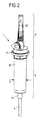
図2は、例えば、輸液、輸血、又は非経口栄養法に用いることができるドリップチャンバー1の図を示している。ドリップチャンバー1は、第1の部分すなわち頂部2と、第2の部分すなわち底部3とを備える。第1の部分2は、容器5、例えば柔軟なバッグに穿孔するように挿入することができる穿孔針20によって形成される入口を有する。したがって、入口20は、ドリップチャンバー1の入口側において上流の容器5に流体接続をもたらす。第1の部分2は、入口20が接続されるキャップ21を更に備える。
FIG. 2 shows a diagram of a
第1の部分のキャップ21は、第2の部分3のチャンバー部材30に隣接する。チャンバー部材30は、概して円筒形の管形状を有し、十分な弾性及び柔軟性を備え、それにより、チャンバー部材30を圧搾方向Sに圧搾して、チャンバー部材30によって形成されるチャンバー300に流体の流れをもたらすポンプ作用を発揮することができる(例えば図3を参照)。
The
第1の部分2と第2の部分3のチャンバー部材30とは、例えば、ともに糊着することにより互いに接続することができる。ここでは、第1の部分2は、硬質のプラスチック材料から作製することができ、チャンバー部材30の剛性と比較すると高い剛性を有する。詳細には、横断方向の圧搾方向Sにおいてチャンバー部材30を圧搾する場合、第1の部分2は実質的に変形しない。
The
チャンバー部材30は、第1の部分2の反対側の底端部において、チューブ4、例えばPVCチューブとの接続をもたらすコネクタ31に隣接する。ここでは、コネクタ31は、2成分射出成形技法を利用することによりチャンバー部材30と一体成形される。このことは、図3〜図9の実施形態に関して以下により詳細に記載する。
The
図3に示されている第1の実施形態において、実質的にチューブ部材の形状のコネクタ31が、射出成形によってチャンバー部材30へ形成される。コネクタ31は、チャンバー部材30の底部301から突出するスタブセクション302に配置される。コネクタ31は受入れ開口310を形成し、受入れ開口310の直径D2はチューブ4の外径に一致し、それにより、端部41を有するチューブ4がコネクタ31の受入れ開口310に適合することができる。
In the first embodiment shown in FIG. 3, a
チャンバー部材30の底部301にあるスタブセクション302は、外周面において、円錐状の形状を有することができる。スタブセクション302は、外周面において、コネクタ31がスタブセクション302に一体的に接続されるように、スタブセクション302上に成形されるコネクタ31によって周囲を囲まれる。
The
スタブセクション302内には、出口開口309が形成され、チャンバー部材30内のチャンバー300と、コネクタ31を介してチャンバー部材30に接続されるチューブ4との間に流れ接続をもたらす。出口開口309は、チューブ4の内部ルーメン40の直径に一致する直径D1を有する。したがって、チューブ4をスタブセクション302に突き当たるまで受入れ開口310に挿入する場合、スタブセクション302の出口開口309とチューブ4の内部ルーメン40との間に段差が形成されない。これにより、出口開口309から内部ルーメン40に移行する際の乱流の発生のリスクが低減され、ひいては下流への流れにおける気泡の発生のリスクも減少する。
An
チャンバー部材30は第1の材料から作製され、一方、コネクタ31は、第1の材料とは異なる第2の材料から作製される。詳細には、チャンバー部材30は、比較的小さい弾性率を有する材料で作製され、そのため、チャンバー部材30は、横断方向の圧搾方向Sにおいて圧搾することができ、このために十分な弾性、柔軟性、及び弾力性がある。
The
これに対して、コネクタ31は、チューブ4に確実かつ耐久性のある接続をもたらすために、チャンバー部材30と比較すると高い剛性を有する。詳細には、コネクタ31の材料は、チャンバー部材30の材料よりも高い弾性率を有する。
On the other hand, the
例えば、チャンバー部材30は第1のタイプのポリスチレンから作製することができ、一方、コネクタ31は、より堅い第2のタイプのポリスチレン、又はメチルメタクリレートアクリロニトリルブタジエンスチレン(MABS)で作製することができる。
For example, the
図3に示されているように、チャンバー300の底部には、チャンバー300を出口開口309から分割する膜320が配置されている。したがって、医療用流体は、チャンバー300を出るのに膜320を通過しなければならない。図3の実施形態において、膜320は、リング状の固定部分321、322に挟まれて保持され、リング状の固定部分321、322は、膜の周縁部323を間に挟んで受け、例えば、チャンバー部材30の底部セクション304に糊着することができる。
As shown in FIG. 3, a
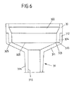
第2の実施形態は図4〜図6に示されている。 A second embodiment is shown in FIGS.
この実施形態内において、コネクタ31は、内部にチューブ4の端部41を受ける受入れ開口310を形成するスタブセクション314を備える。スタブセクション314は、円錐形セクション311を介して接続セクション312に接続され、接続セクション312を介してチャンバー部材30に接続される。円錐形セクション311は、接続セクション312からスタブセクション314に向かってテーパーが付いており、そのため、チャンバー300からの流体が、スタブセクション314及びスタブセクション314に配置されたチューブ4に向かって導かれる。
Within this embodiment, the
接続セクション312は、チャンバー部材30の底部セクション304の周囲を囲む。ここでは、リング状の接続セクション312が底部セクション304を囲み、底部セクション304は、チャンバー300の下端部においてチャンバー部材30の底縁領域に対応する。
The
ここでも、コネクタ31は、射出成形を用いてチャンバー部材30へ一体成形される。チャンバー部材30は、コネクタ31において、上述した材料から形成することができる。
Again, the
図4〜図6の実施形態において、膜320は、コネクタ31の円錐形セクション311と接続セクション312との接続場所において、チャンバー部材30の底部セクション304の端面305と面313とに挟まれて配置することができる。端面305及び面313は、それぞれチャンバー部材30及びコネクタ31の円錐形セクション311において周方向に延在し、端面305と面313との間に膜320の縁部323を保持する。
In the embodiment of FIGS. 4-6, the
ここでは、膜320は、コネクタ31をチャンバー部材30上に射出成形する間、ドリップチャンバー1内に一体的に締結することができる。それにより、膜320を締結する別個の締結ステップが必要とされない。
Here, the
別の実施形態が図7〜図9に示されている。この実施形態は、円錐形セクション306がチャンバー部材30の底部セクション304に隣接し、円錐形セクション306は、スタブセクション307に向かうテーパーがコネクタ31のスタブセクション314内に達している円錐状の形状を有するという点で、図4〜図6の実施形態とは異なる。
Another embodiment is shown in FIGS. In this embodiment, the
チャンバー部材30のスタブセクション307には、出口開口309が形成され、出口開口309の直径D1は、コネクタ31に取り付けられるチューブ4の内部ルーメン40の直径D1に対応する。出口開口309は挿入開口308に隣接し、挿入開口308は、コネクタ31の受入れ開口310と位置合わせされる。詳細には、挿入開口308は、受入れ開口310の直径D2及びチューブ4の外径D2と一致する直径D2を有し、そのため、チューブ4は、端部41を受入れ開口310に挿入することができ、チャンバー部材30のスタブセクション307の挿入開口308に達するまで押し進めることができる。
An
したがって、チューブ4がコネクタ31に挿入されている状態では、スタブセクション307に形成される出口開口309は、チューブ4の内部ルーメン40と位置合わせされ、それにより、出口開口309とチューブ4の内部ルーメン40との間の遷移部に段差が生じない。したがって、ドリップチャンバー1から流れ出る出口流に乱流及び気泡が生じるリスクが低減される。
Accordingly, in the state in which the tube 4 is inserted into the
さらに、コネクタ31の受入れ開口310とチャンバー部材30にある挿入開口308とはともにチューブ受け部を形成し、このチューブ受け部により、異なる材料を有するコネクタ31及びチャンバー部材30の双方にチューブ4を糊着することが可能になる。チューブ4が糊着されると、チャンバー部材30とコネクタ31との間の遷移部がチューブ4の表面によって覆われ、ひいてはシールされることにより、更なる密封性がもたらされる。
Furthermore, the receiving
図7〜図9の実施形態において、コネクタ31は、チャンバー部材30のスタブセクション307、円錐形セクション306、及び底部セクション304にオーバーモールド成形される。
In the embodiment of FIGS. 7-9, the
図7、図8A、及び図9に示されているように、出口流を濾過する膜320は、チャンバー部材30の円錐形セクション306の内側に形成される周方向平面305’に締結される。面305’は、円錐形セクション306と底部セクション304との間の接続位置に構成される。膜320は、例えば、ホットスタンプ加工、別の溶接技法、又は糊着によって面305’に締結することができる。
As shown in FIGS. 7, 8 A and 9, the
ここでも、チャンバー部材30及びコネクタ31は、異なる材料で作製することができる。このような材料の例は上述されている。
Again, the
本発明の根底にある構想は、上述の実施形態に限定されず、全体的に異なる実施形態においても実施することができる。 The concept underlying the present invention is not limited to the above-described embodiments, and can be implemented in entirely different embodiments.
詳細には、チャンバー部材とそのコネクタとを備えるドリップチャンバーは、上述したものとは異なる設計を有してもよい。チャンバー部材とコネクタとの間における異なる一体接続部も可能である。例えば、コネクタは必ずしもチャンバー部材の底部を囲む必要はなく、チャンバー部材内に達してもよい。 Specifically, a drip chamber comprising a chamber member and its connector may have a different design than that described above. Different integral connections between the chamber member and the connector are possible. For example, the connector does not necessarily have to surround the bottom of the chamber member and may reach into the chamber member.
さらに、上述したものとは異なる材料でチャンバー部材及びコネクタを形成することが可能である。例えば、異なる熱可塑性材料を用いて、チャンバー部材及びコネクタを作製することが可能である。 Furthermore, the chamber member and the connector can be formed of a material different from that described above. For example, chamber members and connectors can be made using different thermoplastic materials.
熱溶接、超音波溶接、溶剤溶接、及び/又は糊着による、チャンバー部材30及びコネクタ30に対する代替的な接続技術が可能である。
Alternative connection techniques to
1 ドリップチャンバー
2 第1の部分
20 入口(穿孔針)
21 キャップ
3 第2の部分
30 チャンバー部材
300 チャンバー
301 底部
302 首部
304 底部セクション
305 端面
305’ 面
306 円錐形セクション
307 スタブセクション
308 挿入開口
309 出口開口
31 コネクタ
310 受入れ開口
311 円錐形セクション
312 接続セクション
313 面
314 スタブセクション
32 膜装置
320 膜
321、322 固定部分
323 膜の縁部
4 チューブ
40 ルーメン
41 端部
5 容器(柔軟なバッグ)
6 スタンド
D1、D2 内径
F 流れ方向
P 患者
S 圧搾方向
1 Drip chamber 2
21
6 Stand D1, D2 Inside diameter F Flow direction P Patient S Squeezing direction
Claims (15)
チャンバー(300)を形成するチャンバー部材(30)と、
前記チャンバー(300)に医療用流体を入れる入口(20)と、
該ドリップチャンバー(1)の出口において前記チャンバー部材(30)に接続されるコネクタ(31)と、を備え、
前記チャンバー(300)から前記医療用流体を出すように前記コネクタにはチューブ(4)が接続可能であり、
前記コネクタ(31)は、射出成形を用いて前記チャンバー部材(30)へ一部品として形成され、前記チャンバー部材(30)は第1の材料から形成され、前記コネクタ(31)は、前記第1の材料とは異なる第2の材料から形成されることを特徴とする、ドリップチャンバー。 A drip chamber (1) for administration of medical fluid, the drip chamber (1) comprising:
A chamber member (30) forming a chamber (300);
An inlet (20) for introducing a medical fluid into the chamber (300);
A connector (31) connected to the chamber member (30) at the outlet of the drip chamber (1),
A tube (4) can be connected to the connector so as to draw the medical fluid from the chamber (300),
The connector (31) is formed as a single part on the chamber member (30) using injection molding, the chamber member (30) is formed of a first material, and the connector (31) is formed of the first member. A drip chamber, wherein the drip chamber is formed from a second material different from the first material.
前記受入れ開口(310)は、前記出口開口(309)の前記直径(D1)と比較するとより大きい直径(D2)を有することを特徴とする、請求項7に記載のドリップチャンバー。 The receiving opening (310) is adjacent to an outlet opening (309) formed in the connector (31) or the chamber member (30) and provides a flow connection to the chamber (300);
Drip chamber according to claim 7, characterized in that the receiving opening (310) has a larger diameter (D2) compared to the diameter (D1) of the outlet opening (309).
前記挿入開口(308)は、前記スタブセクション(307)に形成される出口開口(309)に隣接し、前記チャンバー(300)に流体接続をもたらし、
前記挿入開口(310)は、前記出口開口(309)の前記直径(D1)と比較するとより大きい直径(D2)を有することを特徴とする、請求項1〜11のいずれか1項に記載のドリップチャンバー。 The chamber member (30) comprises a stub section (307) extending into the connector (31) and forming an insertion opening (308) for receiving the end (41) of the tube (4),
The insertion opening (308) is adjacent to an outlet opening (309) formed in the stub section (307) and provides a fluid connection to the chamber (300);
12. The insertion opening (310) according to any one of the preceding claims, characterized in that it has a larger diameter (D2) compared to the diameter (D1) of the outlet opening (309). Drip chamber.
前記膜(320)は前記チャンバー(300)を前記出口から分離することを特徴とする、請求項1〜12のいずれか1項に記載のドリップチャンバー。 In the membrane (320), the peripheral edge (323) of the membrane is connected to the surface (305) of the chamber member (30) or the surface (313) of the connector (31),
A drip chamber according to any one of the preceding claims, characterized in that the membrane (320) separates the chamber (300) from the outlet.
前記ドリップチャンバー(1)は、チャンバー(300)を形成するチャンバー部材(30)と、前記チャンバー(300)に医療用流体を入れる入口(20)と、出口において前記チャンバー部材(30)に接続されるコネクタ(31)と、を備え、前記チャンバー(300)から前記医療用流体を出すように前記コネクタにはチューブ(4)が接続可能であり、
前記コネクタ(31)を、2成分射出成形技法を用いて前記チャンバー部材(30)と一部品として形成し、前記チャンバー部材(30)を第1の材料から形成し、前記コネクタ(31)を前記第1の材料とは異なる第2の材料から形成することを特徴とする、製造方法。 A manufacturing method for manufacturing a drip chamber (1) for administration of medical fluid comprising:
The drip chamber (1) is connected to the chamber member (30) forming the chamber (300), an inlet (20) for introducing medical fluid into the chamber (300), and an outlet at the outlet (20). A connector (31), and a tube (4) is connectable to the connector so as to discharge the medical fluid from the chamber (300),
The connector (31) is formed as one part with the chamber member (30) using a two-component injection molding technique, the chamber member (30) is formed from a first material, and the connector (31) is A manufacturing method, wherein the second material is different from the first material.
Applications Claiming Priority (3)
| Application Number | Priority Date | Filing Date | Title |
|---|---|---|---|
| EP14170171 | 2014-05-28 | ||
| EP14170171.4 | 2014-05-28 | ||
| PCT/EP2015/058496 WO2015180892A1 (en) | 2014-05-28 | 2015-04-20 | Drip chamber for administering a medical fluid |
Publications (1)
| Publication Number | Publication Date |
|---|---|
| JP2017516570A true JP2017516570A (en) | 2017-06-22 |
Family
ID=50943058
Family Applications (1)
| Application Number | Title | Priority Date | Filing Date |
|---|---|---|---|
| JP2016569999A Pending JP2017516570A (en) | 2014-05-28 | 2015-04-20 | Drip chamber for administration of medical fluid |
Country Status (5)
| Country | Link |
|---|---|
| US (1) | US20170151385A1 (en) |
| EP (1) | EP3148609A1 (en) |
| JP (1) | JP2017516570A (en) |
| CN (1) | CN106413770A (en) |
| WO (1) | WO2015180892A1 (en) |
Families Citing this family (5)
| Publication number | Priority date | Publication date | Assignee | Title |
|---|---|---|---|---|
| JP6774251B2 (en) * | 2016-07-29 | 2020-10-21 | 三菱鉛筆株式会社 | Intravenous device |
| USD816831S1 (en) * | 2017-04-05 | 2018-05-01 | Alcor Scientific, Inc. | Drip chamber |
| EP3787711A1 (en) * | 2018-05-04 | 2021-03-10 | Poly Medicure Limited | Improved intravenous infusion set |
| JP7236912B2 (en) * | 2018-07-10 | 2023-03-10 | 旭化成メディカル株式会社 | Heating panel manufacturing method, heating panel and channel holding device |
| DE102020204611A1 (en) * | 2020-04-09 | 2021-10-14 | B. Braun Melsungen Aktiengesellschaft | Process for the production of a drip chamber, drip chamber, infusion or transfusion system |
Family Cites Families (6)
| Publication number | Priority date | Publication date | Assignee | Title |
|---|---|---|---|---|
| US3003500A (en) * | 1955-12-14 | 1961-10-10 | Baxter Laboratories Inc | Intravenous administration equipment |
| US4136692A (en) * | 1976-02-19 | 1979-01-30 | Michael Goldowsky | Flow meter administration device |
| US4340050A (en) * | 1980-12-29 | 1982-07-20 | Delmed Inc. | Medical fluid flow rate indicating/controlling device |
| SE9300448L (en) * | 1993-02-11 | 1994-02-07 | Gambro Dialysatoren | Drip and / or expansion chamber with built-in filter and method for making one |
| JP3704008B2 (en) * | 1999-10-14 | 2005-10-05 | 株式会社トップ | Joining method with synthetic resin parts |
| IL133495A (en) * | 1999-12-13 | 2006-12-31 | Menahem Kraus | Membrane support for drip chamber |
-
2015
- 2015-04-20 EP EP15716092.0A patent/EP3148609A1/en not_active Withdrawn
- 2015-04-20 JP JP2016569999A patent/JP2017516570A/en active Pending
- 2015-04-20 US US15/310,365 patent/US20170151385A1/en not_active Abandoned
- 2015-04-20 CN CN201580027263.4A patent/CN106413770A/en active Pending
- 2015-04-20 WO PCT/EP2015/058496 patent/WO2015180892A1/en active Application Filing
Also Published As
| Publication number | Publication date |
|---|---|
| CN106413770A (en) | 2017-02-15 |
| WO2015180892A1 (en) | 2015-12-03 |
| EP3148609A1 (en) | 2017-04-05 |
| US20170151385A1 (en) | 2017-06-01 |
Similar Documents
| Publication | Publication Date | Title |
|---|---|---|
| JP6835883B2 (en) | Single-use delivery device with primer element | |
| AU2019219775B2 (en) | Clip syringe | |
| JP2017516570A (en) | Drip chamber for administration of medical fluid | |
| CN108367145A (en) | Female connector | |
| JP5878479B2 (en) | Insert for medicine injection | |
| JP6002689B2 (en) | Coupling device and kit | |
| CN209809178U (en) | Medical infusion pipeline | |
| CN201179271Y (en) | One-way positive pressure valve | |
| CN209770998U (en) | Automatic liquid-stopping and automatic-exhausting dropping funnel | |
| KR200470517Y1 (en) | Drip chamber of medical injection set | |
| JP4066222B2 (en) | Connector with automatic opening / closing valve and medical device using the same | |
| CN201179272Y (en) | One-way positive pressure valve | |
| CN108785793B (en) | Injection member and infusion apparatus comprising same | |
| JP5255344B2 (en) | Mixed injection material | |
| CN201755344U (en) | Disposable precision filter syringe | |
| JP2016047116A (en) | Connection adapter | |
| TWM519521U (en) | Y-shaped connector device of positive pressure needle-free injection | |
| JPWO2015146458A1 (en) | Medical container, film welding method and container manufacturing method | |
| JP2011217945A (en) | Drip tube | |
| JPH11216190A (en) | Adapter for mixed injection |