JP2017515744A - Automatic bicycle pedal - Google Patents
Automatic bicycle pedal Download PDFInfo
- Publication number
- JP2017515744A JP2017515744A JP2016568588A JP2016568588A JP2017515744A JP 2017515744 A JP2017515744 A JP 2017515744A JP 2016568588 A JP2016568588 A JP 2016568588A JP 2016568588 A JP2016568588 A JP 2016568588A JP 2017515744 A JP2017515744 A JP 2017515744A
- Authority
- JP
- Japan
- Prior art keywords
- pedal
- cleat
- hook
- latch member
- bevel
- Prior art date
- Legal status (The legal status is an assumption and is not a legal conclusion. Google has not performed a legal analysis and makes no representation as to the accuracy of the status listed.)
- Granted
Links
Images
Classifications
-
- B—PERFORMING OPERATIONS; TRANSPORTING
- B62—LAND VEHICLES FOR TRAVELLING OTHERWISE THAN ON RAILS
- B62M—RIDER PROPULSION OF WHEELED VEHICLES OR SLEDGES; POWERED PROPULSION OF SLEDGES OR SINGLE-TRACK CYCLES; TRANSMISSIONS SPECIALLY ADAPTED FOR SUCH VEHICLES
- B62M3/00—Construction of cranks operated by hand or foot
- B62M3/08—Pedals
- B62M3/086—Attachments between shoe and pedal other than toe clips, e.g. cleats
Landscapes
- Engineering & Computer Science (AREA)
- Chemical & Material Sciences (AREA)
- Combustion & Propulsion (AREA)
- Transportation (AREA)
- Mechanical Engineering (AREA)
- Footwear And Its Accessory, Manufacturing Method And Apparatuses (AREA)
- Mechanical Control Devices (AREA)
Abstract
自動自転車ペダルは、ペダルクランクに結合されるのに適したスピンドル(20)に回転連結されたペダル本体(130)を備え、上記ペダル本体(130)は、前後方向(A)を有し、クリート(220)によって係合可能な前部(122)および後部(124)を備え、上記クリート(220)は、乗り手の靴のソールに接続可能であり、前フック(233)および後フック(232)を備え、上記前部(122)は、上記クリート(220)の前フック(233)ための可撓性の係合手段(132、134)を備える。The automatic bicycle pedal includes a pedal body (130) rotationally connected to a spindle (20) suitable for being coupled to a pedal crank, the pedal body (130) having a front-rear direction (A) and a cleat. A front portion (122) and a rear portion (124) engageable by (220), the cleat (220) being connectable to a rider's shoe sole, a front hook (233) and a rear hook (232) The front portion (122) includes flexible engagement means (132, 134) for the front hook (233) of the cleat (220).
Description
出願人:Selle Royal S.p.A.
本発明の技術分野
本発明は、自動自転車ペダルに関する。
Applicant: Sell Royal S. p. A.
TECHNICAL FIELD OF THE INVENTION The present invention relates to an automatic bicycle pedal.
自動自転車ペダルは、従来、靴のソールに取り付けられるクリートを保持するために使用される取り付け手段を有する、前および後に提供されるペダル本体を備える。 An automatic bicycle pedal conventionally comprises a pedal body provided in front and behind, with attachment means used to hold cleats attached to the sole of the shoe.
そのようなペダルは、元々相対的に多くの部品パーツを有した。
このため、米国特許第6,564,676号に示されるように、ペダル本体に加えて、それらは、ペダルクランク上に取り付けるために、スピンドル、リング、回転ベアリング等を備え、そのペダル本体上でそれが回転するように取り付けられるカートリッジスピンドルアセンブリと、ピボット軸の周りで本体に関節式につながれた後レバーと、レバーをプリロードするための弾性システムとを備えるだろう。
Such pedals originally had relatively many component parts.
For this reason, as shown in US Pat. No. 6,564,676, in addition to the pedal body, they comprise a spindle, ring, slewing bearing, etc. for mounting on the pedal crank on the pedal body. It would comprise a cartridge spindle assembly that is mounted for rotation, a rear lever articulated about the pivot axis to the body, and a resilient system for preloading the lever.
たとえば弾性システムは、金属またはエラストマばね、曲げや座屈等に作用するブレード等から生産される。 For example, elastic systems are produced from metal or elastomer springs, blades acting on bending, buckling and the like.
後関節式レバーによって、その構造的な複雑性によって、引き起こされる1つの問題は、乗り手がペダルストローク中に後側に引くときに、後関節式レバーばねが開き、ペダリングが不十分になるほどに、そしてクリート/ペダルが消耗するほどにクリートを背側に摺動させることである。 One problem caused by the structural complexity of the rear joint lever is that when the rider pulls backwards during the pedal stroke, the rear joint lever spring opens and pedaling is insufficient, Then, the cleat is slid back so that the cleat / pedal is consumed.
極端な場合、またはペダル力が低すぎるように調整されるとき、クリートは前部との係合を解除する背側に十分に遠くに摺動することができ、乗り手の足が突然ペダルから抜け出す。 In extreme cases, or when the pedal force is adjusted to be too low, the cleat can slide far enough back to disengage the front and the rider's foot suddenly comes off the pedal .
いくつかの既知のペダル本体は、たとえば、米国特許出願第2012/0067165号、米国特許第5,381,708号、および米国特許5,105,683号に開示されるように、可撓性の後レバーを、ばねが搭載されたピボット軸の周りに回転式につながる後レバーの代わりに有する。 Some known pedal bodies are flexible, as disclosed, for example, in US 2012/0067165, US Pat. No. 5,381,708, and US Pat. No. 5,105,683. A rear lever is provided in place of the rear lever that is pivoted about a pivot axis on which a spring is mounted.
これらのペダルは、部品の数および重さを減らすが、クリートのリリースを調整するための手段を提供せず、後を下に吊るす重みが付勢されず、ペダル自体を第1に再度位置決めすることなく係合を不可能とする位置にペダルが何回か配向されることがあり得るために、係合をより難しくする。 These pedals reduce the number and weight of parts, but do not provide a means for adjusting the release of the cleats, the weights that suspend the back are not biased, and the pedals themselves are repositioned first. Engagement is made more difficult because the pedal may be oriented several times in a position where it is impossible to engage without it.
既存の自動ペダルの大多数が、係合し、リリースのためにねじるためにステップインおよびダウンモーションを要し、これはとても一般的であるので、多くの乗り手がこの動作に慣れている。 The majority of existing automatic pedals require step-in and down-motion to engage and twist for release, which is so common that many riders are accustomed to this movement.
さらに、異なる乗り手は、異なる量のリリース力を好む。
現在、リリース調整を有する既存のペダルでは、リリース力が増加され、クリート係合の力はまた増加される。
Furthermore, different riders prefer different amounts of release power.
Currently, with existing pedals having a release adjustment, the release force is increased and the cleat engagement force is also increased.
乗り手がクリート力をより高く調整するとき、それは通常、彼らは不測のリリースを防ぎたく、彼らが回転フロートを極めて自明に制限したく、加えて、彼らがリリースを始めるときを彼らは非常に意識したいためである。 When riders adjust the cleat force higher, it is usually they are very conscious of when they want to start the release, in addition they want to prevent accidental release, they want to limit the rotational float very obvious Because I want to.
しかし、同じ乗り手は、より難しい入力を望まない。
既存のペダルでは、後取り付け手段を有するが、クリートは、ペダル本体の前に踏み込んだ後、下に踏み込んで、後取り付け手段を後ろに移動させることにより係合される。
However, the same rider does not want more difficult input.
Existing pedals have rear attachment means, but the cleats are engaged by stepping in front of the pedal body and then down and moving the rear attachment means back.
クリートの前向きの移動は、直接係合を補助せず、その代わりに下向き移動が実際には係合を引き起こす。 The forward movement of the cleats does not assist direct engagement, but instead the downward movement actually causes engagement.
「回転フロート」という表現は、クリートと本体との間の係合を維持した状態での回転移動を意味する。 The expression “rotational float” means a rotational movement in a state in which the engagement between the cleat and the main body is maintained.
回転フロートは、典型的に、度で測定され、自動ペダルでは、0の小さい値から異なることができ、また最大30度で「固定され」るが、5〜10度が最も典型的である。 Rotational float is typically measured in degrees, and with an automatic pedal it can vary from a small value of 0 and is “fixed” at up to 30 degrees, with 5-10 degrees being most typical.
回転フロートは、異なるクリートを使用することによってか、クリート内の予測されたメカニズムを調整することによって通常調整されることができる。 The rotational float can usually be adjusted by using different cleats or by adjusting the predicted mechanism within the cleat.
発明の目的
本発明の技術的目的は、このため従来技術を向上することである。
OBJECT OF THE INVENTION The technical object of the present invention is therefore to improve the prior art.
そのような技術的目的の範囲において、本発明の目的の1つは、簡略化された構造的特徴および削減された製造コストを有する自動自転車ペダルを開発することである。本発明の他の目的は、削減された重さを有する自動自転車ペダルを提供することである。 Within the scope of such technical objectives, one of the objectives of the present invention is to develop an automatic bicycle pedal with simplified structural features and reduced manufacturing costs. Another object of the present invention is to provide an automatic bicycle pedal having a reduced weight.
本発明のさらなる目的は、ペダル本体内への足の改善されたクリッピングを有する自動自転車ペダルを開発するとともに、独立したリリースための調整を提供することである。 It is a further object of the present invention to develop an automatic bicycle pedal with improved clipping of the foot into the pedal body and to provide independent release adjustments.
本発明のさらに別の目的は、クリートの前向きの動きが直接係合手段を開くことをもたらす自動自転車ペダルを提供することである。 Yet another object of the present invention is to provide an automatic bicycle pedal that provides for the forward movement of the cleat to directly open the engagement means.
この目的およびこれら目的は、添付された請求項1に従う自動自転車ペダルによってすべて達成される。 This object and these objects are all achieved by an automatic bicycle pedal according to the appended claim 1.
さらに、この目的およびそれらの目的は、請求項13に係るクリートによってすべて達成される。 Furthermore, this object and those objects are all achieved by the cleat according to claim 13.
本発明に係る自動自転車ペダルは、ペダルクランクに結合されるのに適したスピンドルに回転連結されたペダル本体を備える。 The automatic bicycle pedal according to the present invention comprises a pedal body that is rotationally connected to a spindle suitable for being coupled to a pedal crank.
ペダル本体は、前後方向を規定し、乗り手の靴のソールに接続可能であり前フックおよび後フックを備えるクリートによって係合可能な前部および後部を備える。 The pedal body includes a front portion and a rear portion that define a front-rear direction and are connectable to a sole of a rider's shoe and engageable by a cleat including a front hook and a rear hook.
ペダル本体の前部は、クリートの前フックのための可撓性の係合手段を備える。
ペダル本体の前部内に提供される可撓性の係合手段は、係合力が全体でリリース力から独立となるように、ペダル本体内へのクリートの係合力の量を決定する。
The front part of the pedal body is provided with flexible engaging means for the front hook of the cleat.
A flexible engagement means provided in the front of the pedal body determines the amount of cleat engagement force into the pedal body such that the engagement force is totally independent of the release force.
請求項5によれば、後部は、ペダル本体がラッチ部材を備える場合、それぞれのシート内でペダル本体の前後方向に沿って選択的に摺動可能である。 According to the fifth aspect, the rear portion is selectively slidable along the front-rear direction of the pedal body within each seat when the pedal body includes a latch member.
ペダル本体自体の後部に対するペダル本体の前後方向に沿うラッチ部材の相対的位置は、全体的に係合力から独立して、ペダル本体によってクリートのリリース力の量を決定する。 The relative position of the latch member along the longitudinal direction of the pedal body relative to the rear of the pedal body itself determines the amount of cleat release force by the pedal body, independent of the engagement force as a whole.
請求項6によれば、ラッチ部材はクリートの後フックのそれぞれの溝に係合するのに適した傾斜プロファイルを有する外面を備える。乗り手の靴のソールに接続可能な本発明に係るクリートは、ペダル本体の前部内および後部内にそれぞれ係合可能な前フックおよび後フックを設けられ、クリートの後フックは、そのような溝が規定される2つの突出部を備える。 According to claim 6, the latch member comprises an outer surface having an inclined profile suitable for engaging the respective groove of the rear hook of the cleat. The cleat according to the present invention, which can be connected to the sole of the shoe of the rider, is provided with a front hook and a rear hook which can be engaged in the front part and the rear part of the pedal body, respectively. With two defined protrusions.
従属請求項は、望ましく有利な本発明の実施形態に言及する。
図面の簡単な説明
これらの利点および他の利点は、非限定的な例として与えられる以下の説明および添付の図面から、当業者によってよりよく理解されるであろう。
The dependent claims refer to desirable and advantageous embodiments of the invention.
BRIEF DESCRIPTION OF THE DRAWINGS These and other advantages will be better understood by those skilled in the art from the following description and the accompanying drawings given by way of non-limiting example.
発明の実施形態
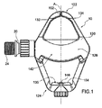
図1の図示の概略図を参照して、本発明に係る自動自転車ペダルは、全体として10と示される。
DETAILED DESCRIPTION OF THE INVENTION Referring to the illustrated schematic diagram of FIG. 1, an automatic bicycle pedal according to the present invention is indicated generally as 10.
以下の実施形態では、特定の実施形態に関連して与えられる個々の特性は、実際には他の実施形態に存在する他の異なる特性と相互変換されてもよい。 In the following embodiments, individual characteristics given in connection with a particular embodiment may actually be interconverted with other different characteristics that exist in other embodiments.
本発明に係る自動ペダルは、自転車のいずれの種に容易に搭載されることができ、望ましくは、しかし非限定的に、本発明に係るペダルは、ロード自転車等に搭載される。 The automatic pedal according to the present invention can be easily mounted on any kind of bicycle. Desirably, but not exclusively, the pedal according to the present invention is mounted on a road bicycle or the like.
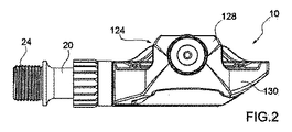
ペダル10は、ペダル本体130を備える。
ペダル本体130は、スピンドル20に回転連結され、スピンドル20は、ペダルクランクに結合されるのに適している。
The
The
示されるスピンドル20の形状は、ストレスライザーを最小化するために滑らかであり、長さの大部分にわたってテーパ状である。
The shape of the
スピンドル20は、チタン、または他の適した材料で作られることができる。
ペダル本体130は、用途のためのいずれかの適した材料で作られることができる。
The
The
たとえばそれは、ポリマー性材料で作られることができる。
1つの望ましい材料は、炭素強化されたポリマーであり得る。
For example, it can be made of a polymeric material.
One desirable material can be a carbon reinforced polymer.
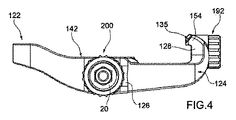
ペダル本体130は、前後方向Aを有するか規定する。
ペダル本体130は、前部122および後部124を備える。
The
The
ペダル本体130は、中央部分126をさらに備える。
中央部分126は、クリート220に接触するのに適した上部表面142を規定する。
The
ペダル本体130の後部124は、突起128を備える。
突起128は、ペダル本体130の前後方向Aに実質的に垂直である。
The
The
スピンドル20は、クランクアームへの接続のためのねじ付き先端部24を備える。
スピンドル20は、カートリッジアセンブリ200を用いてペダル本体130に接続される。
The
The
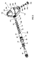
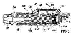
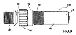
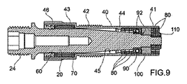
カートリッジアセンブリは、図8、9に詳細に示される。
カートリッジアセンブリ200は、ペダル本体130の中央部分126内に設けられる円筒状のシート202の内側に収容される。
The cartridge assembly is shown in detail in FIGS.
The
円筒状のシート202は、ねじ付き端部136を備える。
カートリッジアセンブリ200は、カートリッジ本体40を備える。
The
The
カートリッジ本体40は、実質的に管状形状を有し、それは第1の端部41および第2の端部43を備える。
The
カートリッジ本体40は、アルミニウム、またはいずれか他の適した材料で作られることができる。
The
第1の端部41は、スプライン46を備え、第1の端部41と第2の端部43との間にねじ山部分42を見越む。
The
ねじ山部分42は、カートリッジ本体40をペダル本体130の中央部分126に安全に接続するために、円筒状のシート202のねじ付き端部136内にねじ込まれる。
The threaded
スプライン46は、カートリッジ本体40がペダル本体130内に容易にねじ込まれることを可能とする。
The
カートリッジアセンブリ200は、スピンドル20をカートリッジ本体40の第1の端部によって回転的に支持する針の種類の第1のベアリング70を備える。
The
針ベアリング70は、強度および耐久性のために望ましく、針ベアリング70は、ブッシングによって置き換えられ得る。
Needle bearing 70 is desirable for strength and durability, and
シール60は、針ベアリング70上に当接し、カートリッジ本体40開口部を閉じ、汚染がカートリッジ本体40自体に入るのを防ぐ。
The
スピンドル20は、カートリッジ本体40の第2の端部によってと、第2のベアリング90によってと、第3のベアリング100によって回転的に支持される。
The
2つのベアリング90、100は、強度および耐久性のために望ましいが、それらは単一のベアリングまたはブッシングによって置き換えられ得る。
Two
ベアリング90、100は、スピンドル20内に見越される当接部92に配置され、それらはスピンドル20のねじ付き端部上にねじ込まれるナット110によって保持される。
The
円筒状のシート202へとOリングシール120は収容され、その上にカートリッジ本体40の第2の端部43が当接する。
The O-
カートリッジ本体40の内面45は、リップ44を備える。
複数のスペーサ80は、リップ44および第2のベアリング90の間と、第3のベアリング100およびOリングシール120の間とに挟まれる。
The
The plurality of
図示された本発明の実施形態では、スペーサ80は、5つでありスペーサ80の数は特定の必要条件を満たすために任意である。
In the illustrated embodiment of the invention, there are five
スペーサ80は、アルミニウム、またはいずれか他の適した材料で作られることができる。
スペーサ80は、いわゆるペダル10の「Qファクタ」、すなわち乗り手の足の中心間距離、またはより具体的にはクリートの中心線から自転車クランクアームへの距離を変形するために再配置されることができる。スペーサ80の厚さは任意であり、たとえば1mmまたは2mmであることができる。
The
たとえば、ペダル10の3つの異なるQファクタに対応するカートリッジアセンブリ200の3つの可能な構成は、それぞれ図5、6、7に示される。
For example, three possible configurations of the
図5では、あるQファクタ値に対応する第1の構成が示され、3つのスペーサ80は、スピンドル20に沿って、リップ44と第1のベアリング90との間に配置され、同時に2つのスペーサ80は、第2のベアリング100とOリングシール120との間に配置される。
In FIG. 5, a first configuration corresponding to a certain Q factor value is shown, and three
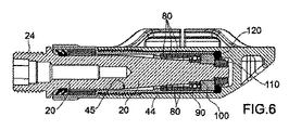
図6では、ペダル10の最小Qファクタ値に対応する構成が示される。
この構成では、すべてのスペーサ80は、スピンドル20に沿って、リップ44と第1のベアリング90との間に配置される。
In FIG. 6, the structure corresponding to the minimum Q factor value of the
In this configuration, all
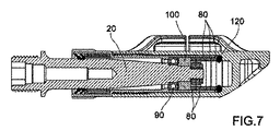
図7では、ペダル10の最大Qファクタ値に対応する構成が示される。
この構成では、すべてのスペーサ80は、スピンドル20に沿って、第2のベアリング100とOリングシール120との間に配置される。
In FIG. 7, the structure corresponding to the maximum Q factor value of the
In this configuration, all
多くの他の中間構成は、ベアリング90、100を除去し所望のQファクタに係るスペーサ80を再配置するために、単にカートリッジ本体40を円筒状のシート202から、ナット110をスピンドル20のねじ付き端部から除去することによって達成されることができる。
Many other intermediate configurations simply remove the
スピンドルカートリッジアセンブリ200は、Qファクタを変えることを便利にするために望ましいが、スピンドル20、ベアリング70、90、100、スペーサ80およびナット110を直接ペダル本体130の円筒状のシート202に組み立てることを可能とするだろう。
The
ペダル本体130の前部122および後部124は、クリート220によって係合可能である。
The
クリート220は、乗り手の靴のソールに接続可能である。
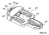
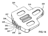
クリート220は、図13、14に詳細に示され、本発明またそのようなクリート220に関する。
The
クリート220は、乗り手のソール(図示されない)への接続のための、図14に見られる上部領域210と、ペダル本体130の上部表面142上に当接するのに適した下方面216を有する図13に見られる低部領域215とを備える。
The
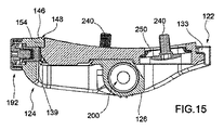
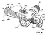
ソールへの接続は、標準であり調整可能であるが、たとえば15、16のワッシャ250を通過するスクリュー240によって達成される。
The connection to the sole is standard and adjustable, but is achieved, for example, by
クリート220は、前フック233および後フック232を備える。
本発明の態様によれば、ペダル本体130の前部122は、クリート220の前フック233のための可撓性の係合手段132、134を備える。
The
In accordance with an aspect of the present invention, the
さらに詳細に、可撓性の係合手段132、134は、第1の可撓性の脚部132を備える。
In more detail, the flexible engagement means 132, 134 includes a first
可撓性の係合手段132、134は、第2の可撓性の脚部134をさらに備える。
第1の可撓性の脚部132および第2の可撓性の脚部134は、ギャップ152によって分離される。
The flexible engagement means 132, 134 further comprises a second
First
ギャップ152は、望ましくは、しかし非限定的にペダル本体130の前後方向Aに沿って配置される。
The
いずれにせよ、ギャップ152は、本発明の特定の実施形態に係る異なる方向に沿って配置されうる。
In any case, the
本発明の他の実施形態では、図示されないが、可撓性の係合手段132、134は、クリート220の前フック233を包む単一の脚部を備えることができる。
In other embodiments of the present invention, although not shown, the flexible engagement means 132, 134 may comprise a single leg that encloses the
他の実施形態では、可撓性の係合手段132、134は1つまたは複数のヒンジさればねが搭載された脚部を、可撓性の脚部の代わりに備えることができる。 In other embodiments, the flexible engagement means 132, 134 may comprise one or more hinged and spring mounted legs instead of the flexible legs.
ギャップ152の幅は、クリート220の前フックの安全な係合と、後の迅速かつ容易な係合解除を保証するために任意の適切なものとすることができる。
The width of the
ギャップ152のそのような幅は、特定の使用者の必要条件に従って、ペダル本体130内のクリート220の異なる係合力を達成するために変形され得る。
Such a width of the
第1の可撓性の脚部132および第2の可撓性の脚部134は両方、実質的にアーク形にされ、本発明の他の実施形態では、それらの形状は特定の必要条件のために任意の適したものであり得る。
Both the first
第1の可撓性の脚部132および第2の可撓性の脚部134は、幅よりも背丈の高い断面を有する。
The first
この特徴のおかげで、脚部132、134は、クリート220を受けるために容易に前方外側へ曲げられうる。
Thanks to this feature, the
さらに、脚部132、134は、クリート220とペダル本体130との間に固い接続を作成するために上向きに堅い。
Further, the
脚部132、134は、少なくともギャップ152の周りの領域で、実質的にL形にされる断面を有する。
したがって、脚部132、134の各々は、内部エッジ133を規定する。
可撓性の係合手段132、134がペダル本体130の前部122内にあることの利点は、クリート220が前方に直接摺動し、徐々に係合手段132、134が離れて曲がるよう寄与し、ペダル10を後係合手段と係合することを簡単にすることである。
Accordingly, each of the
The advantage of the flexible engagement means 132, 134 being in the
別個のばねおよび/またはピボットピンは、既知の種の自動ペダルを特徴付け、このため除去され、より軽く、簡易でより安価な自動ペダルを可能とする。 Separate springs and / or pivot pins characterize known types of automatic pedals and are therefore eliminated, allowing a lighter, simpler and less expensive automatic pedal.
加えて、この特徴のおかげでペダル10は、係合されないときに下方に垂れ下がるための後重さ付勢を有する。
In addition, thanks to this feature, the
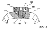
別の発明の態様によれば、ペダル本体130の後部124は、ラッチ部材190を備える。
According to another inventive aspect, the
ラッチ部材190は、特に、図10、11、12に示される。
ラッチ部材190は、前後方向Aに沿って後部124の突起128内に提供されるそれぞれのシート194内で、選択的に摺動可能である。
The
The
より詳細には、ラッチ部材190は、外面191を備える。
ラッチ部材190の外面191は、傾斜プロファイルを有する。
More specifically, the
The
さらに発明の態様によれば、ラッチ部材190は、スクリュー調整手段192を備える。
Further in accordance with an aspect of the invention, the
スクリュー調整手段192は、ラッチ部材190内に係合されるスクリュー170を備える。
The screw adjusting means 192 includes a
スクリュー170は、シート194内にリング160によって保持される。
リング160は、ペダル本体130の後部124と一体であるナット161上にねじ込まれる。
The
The
さらに、スクリュー調整手段192は、ばね180を備える。
ばね180は、スクリュー170をリング160に対して保持する。
Further, the screw adjusting means 192 includes a
The
スクリュー170とリング160との間の接触環状表面は、定期的な位置でスクリュー170を割り出すために使用される戻り止め手段を設けられてもよい。
The contact annular surface between the
後部124の突起128は、後エッジ154を備える。
後エッジ154は、第1の斜面135を規定する。
The
The
後エッジ154は、後歯部146をさらに備える。
後歯部146は、第2の斜面138を規定する。
The
The
第1の斜面135および第2の斜面138は、同じ傾斜を有するが、本発明のある実施形態では、それらは異なる傾斜を有してもよい。
Although the
クリート220の後フック232は、溝236を備える。
さらに詳細に、後フック232は、溝236が規定される2つの突出部238を備える。
The
More particularly, the
溝236は、第3の斜面139を規定する。
突出部238は、実質的にクリート220の下方面216に平行なそれぞれの係合表面237を規定する。
The
The
突出部238は、第4の斜面148のそれぞれ、横方向の斜面226、227のそれぞれを規定する。
The
クリート220の前フック233は、前エッジ234を備える。
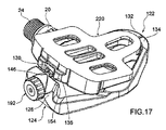
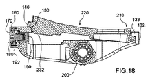
図17、18を参照して、ペダル本体130内へのクリート220の係合中に、クリート220の前エッジ234は、第1のおよび第2の脚部132、134の内部エッジ133の下に係合される。
The
Referring to FIGS. 17 and 18, during the engagement of the
同時に、突出部138の第4の斜面148は、後エッジ154の第1の斜面135と接触し、第2の斜面138は、第3の斜面139と接触する。
At the same time, the
特に、第2の斜面138と第3の斜面139との間の接触は、クリート220を係合中に正しい配向にガイドすることを助ける。
In particular, contact between the
ペダル本体130内へのクリート220の係合を達成するためにユーザが足を下に押すと、斜面148、135と138、139との間の接触は、クリート220自体を前向きに移動することをもたらす。
When the user presses the foot down to achieve engagement of the
それにより、脚部132、134は外側へ曲がり、ギャップ152の幅を一時的に増加させる。
Thereby, the
クリート220はそのため、突出部238の係合表面237が後部124の後エッジ154の下方面と接触する可聴のクリック音とともに図15、16に示される係合位置に達する。
The
この状態では、ラッチ部材190は、溝236内に係合される。
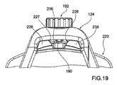
図19に示されるように、ある回転クリートフロートは、ラッチ部材190の外面191と突出部238の横方向の斜面226、227との間に存在するギャップによって保障される。
In this state, the
As shown in FIG. 19, some rotating cleat float is ensured by a gap that exists between the
クリートフロートは、そのため使用者の特定の必要条件に従って、外面191および/または横方向の斜面226、227を変更することによって変えられることができる。
The cleat float can therefore be changed by changing the
ペダル本体130内へのクリート220の係合力は、使用される本体材料、脚部132、134の寸法、クリート220の寸法に応じて異なるだろう。
The engagement force of the
また、回転フロートは、乗り手が使用するクリートに応じて異ならせることができ、非フロートから最大30度のフロートの範囲とされ得る。 Also, the rotational float can vary depending on the cleat used by the rider and can range from non-float to a maximum of 30 degrees float.
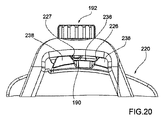
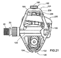
クリート220のペダル本体130からの係合解除は、図20、21に示される。
クリート220をそのフロートを超えて回すことにより、ラッチ部材190は、クリート220自体を前向きに移動させる。
The disengagement of the
By turning the
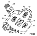
これは、脚部132、134が外側へ曲がることを引き起こし、クリート220の突出部238の1つがラッチ部材190を超えて移動し、そのため図23に示された状態とすることを可能とする。
This causes the
乗り手によって印加されなければならないリリース力は、調整手段192によって正確に調整されることができる。 The release force that must be applied by the rider can be accurately adjusted by the adjusting means 192.
ゼロリリース力の状態は図10に示される。
この状態では、ラッチ部材190は、シート194の内側に十分に引込められ、クリート220の回転に抵抗を提供しない。
The state of zero release force is shown in FIG.
In this state,
特に、クリート220の突出部238の移動の妨害を提供しない。
この状態は、弱い膝または他の物理的問題または彼らが極めて低いリリース力を望む理由を有する乗り手に役立ち得る。
In particular, it does not provide an impediment to movement of the
This condition can be useful for riders who have weak knees or other physical problems or why they want very low release forces.
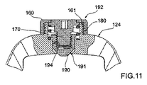
図11では中間状態が示され、あるリリース力は、クリート220をペダル本体130からの係合を解除するために必須である。
In FIG. 11, an intermediate state is shown, and a certain release force is essential to disengage the
ラッチ部材190は、部分的にシート194から出ており、クリート220のペダル本体130からのリリース中に、それは突出部238の1つによって追い越されなければならない。
The
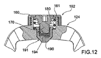
図12では終了状態が示されており、ラッチ部材190は、シート194に対して十分に外側に調整され、最大リリース力はそしてクリート220をペダル本体130からの係合を解除するために必須とされる。
In FIG. 12, the end state is shown and the
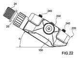
図22では、急な自転車のターン中に起こり得る最大傾斜角度の状態にあるペダル10の背面図が示される。
In FIG. 22, a rear view of the
本発明に係るペダル10のQファクタが調整されることができても、ペダルの傾斜角度は既存のペダルと比較して大きく、ペダルが道路に接触することなく、乗り手はより急な方向にペダルを踏み出すことができる。 Even if the Q factor of the pedal 10 according to the present invention can be adjusted, the inclination angle of the pedal is larger than that of the existing pedal, and the rider does not touch the road, and the rider moves in a steeper direction. Can be stepped on.
大きな量の接触をクリート220とペダル10との間に提供される本発明に係るペダルの構成は、固体接続を乗り手の靴とペダル10との間に提供する。
The pedal arrangement according to the present invention in which a large amount of contact is provided between the
望ましい材料がさまざまな部品に対して選ばれるおかげで、ペダル10は非常に軽く、同時に堅固で信頼性が高い。
Thanks to the choice of the desired material for the various parts, the
ペダル本体130の上部表面142は、本体130の一体部として作られることができるが、たとえばステンレス鋼製の、薄いプレートが改善された摩耗またはフロート感触を提供するために搭載されることができる。
The
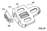
本発明の代替的な実施形態は、図24に示される。
特に、本発明のこの実施形態ではクリート220は、2つの部270、280を備える。
An alternative embodiment of the present invention is shown in FIG.
In particular, in this embodiment of the invention, the
さらに詳細に、クリート220は、クリート本体270および別の後係合手段280を備える。
More particularly, the
クリート本体270は、後係合手段280が取り外し可能に係合されるT形シート272を備える。
The
後係合手段280は、T形シート272内に係合可能なT形突起274を備える。
この解決策は、ユーザがクリートの回転フロートおよび/またはリリース力を、後係合手段280を異なる幾何学的特徴を有する他のものと置き換えることによって、変更することを可能とする。
The rear engagement means 280 includes a T-shaped
This solution allows the user to change the rotational float and / or release force of the cleat by replacing the post-engaging means 280 with another having different geometric features.
たとえば示された実施形態では、突出部238が互いにより近く、そのため溝236がより狭いので、クリート220は、以前の実施形態に対してより少ない回転フロートを有する。
For example, in the illustrated embodiment, the
本発明を好ましい実施形態に従って説明したが、添付の特許請求の範囲によって提供される保護の範囲から逸脱することなく、均等の変形を考案することができる。 Although the invention has been described in accordance with a preferred embodiment, equivalent variations can be devised without departing from the scope of protection provided by the appended claims.
Claims (25)
ペダルクランクに結合されるのに適したスピンドル(20)に回転連結されたペダル本体(130)を備え、前記ペダル本体(130)は、前後方向(A)を有し、前部(122)および後部(124)を備え、前記自動自転車ペダルアセンブリはさらに、
乗り手の靴のソールに接続可能であり、前記ペダル本体(130)の前記前部(122)内および前記後部(124)内にそれぞれ係合可能な前フック(233)および後フック(232)を設けられたクリート(220)を備え、
前記前部(122)は、前記クリート(220)の前記前フック(233)のための可撓性の係合手段(132、134)を備えることを特徴とする、自動自転車ペダルアセンブリ。 An automatic bicycle pedal assembly,
A pedal body (130) rotatably connected to a spindle (20) suitable for being coupled to a pedal crank, said pedal body (130) having a front-rear direction (A), a front part (122) and A rear portion (124), the automatic bicycle pedal assembly further comprising:
A front hook (233) and a rear hook (232) connectable to a sole of a rider's shoe and engageable in the front portion (122) and the rear portion (124) of the pedal body (130), respectively. With a cleat (220) provided,
Automatic bicycle pedal assembly, characterized in that the front part (122) comprises flexible engagement means (132, 134) for the front hook (233) of the cleat (220).
Applications Claiming Priority (3)
| Application Number | Priority Date | Filing Date | Title |
|---|---|---|---|
| ITVR20140138 | 2014-05-19 | ||
| ITVR2014A000138 | 2014-05-19 | ||
| PCT/IB2015/053562 WO2015177692A1 (en) | 2014-05-19 | 2015-05-14 | Automatic bicycle pedal |
Publications (2)
| Publication Number | Publication Date |
|---|---|
| JP2017515744A true JP2017515744A (en) | 2017-06-15 |
| JP6656176B2 JP6656176B2 (en) | 2020-03-04 |
Family
ID=51220836
Family Applications (1)
| Application Number | Title | Priority Date | Filing Date |
|---|---|---|---|
| JP2016568588A Active JP6656176B2 (en) | 2014-05-19 | 2015-05-14 | Auto bicycle pedal |
Country Status (10)
| Country | Link |
|---|---|
| US (2) | US10464630B2 (en) |
| EP (1) | EP3145803B1 (en) |
| JP (1) | JP6656176B2 (en) |
| CN (1) | CN106458284B (en) |
| AU (1) | AU2015262929B2 (en) |
| BR (1) | BR112016027120B1 (en) |
| DK (1) | DK3145803T3 (en) |
| ES (1) | ES2811925T3 (en) |
| TW (1) | TWI718988B (en) |
| WO (1) | WO2015177692A1 (en) |
Cited By (1)
| Publication number | Priority date | Publication date | Assignee | Title |
|---|---|---|---|---|
| JP7100186B1 (en) * | 2021-09-14 | 2022-07-12 | 泰 国本 | Bicycle pedals |
Families Citing this family (10)
| Publication number | Priority date | Publication date | Assignee | Title |
|---|---|---|---|---|
| GB2536444B (en) * | 2015-03-17 | 2018-06-06 | Chain Reaction Cycles Ltd | Pedal for velocipedes |
| US20180111659A1 (en) * | 2016-10-21 | 2018-04-26 | PedalX, LLC | Bicycle Pedal Extension Apparatus |
| US20200031427A1 (en) * | 2017-04-04 | 2020-01-30 | Michael Craig FOUCHE | Cycling cleat and a cycling pedal |
| FR3096651B1 (en) * | 2019-06-03 | 2021-04-23 | Look Cycle Int | Automatic pedal for cycle |
| EP4019382A1 (en) * | 2020-12-22 | 2022-06-29 | Titanum GmbH | Clipless pedal retention system |
| FR3119599B1 (en) * | 2021-02-10 | 2023-12-15 | Pedalissime 2020 | AUTOMATIC PEDAL FOR CYCLE AND ASSEMBLY COMPRISING AN AUTOMATIC PEDAL AND A SHOE |
| TWI773379B (en) * | 2021-06-11 | 2022-08-01 | 謝金龍 | Special-purpose pedal automatic assembly device and assembly method |
| EP4363300A4 (en) * | 2021-06-30 | 2025-03-19 | Smart Clips LLC | MAGNETIC ENGAGEMENT MECHANISM FOR A RECREATIONAL AND/OR TRANSPORTATION DEVICE |
| WO2023165664A1 (en) | 2022-03-03 | 2023-09-07 | Niels Erikstrup | Bicycle pedal and cleat |
| DE102022205206A1 (en) * | 2022-05-24 | 2023-11-30 | Shimano Inc. | Cleat, bicycle pedal, bicycle pedal assembly and bicycle pedal system |
Citations (3)
| Publication number | Priority date | Publication date | Assignee | Title |
|---|---|---|---|---|
| US5634383A (en) * | 1996-03-29 | 1997-06-03 | Lin; Wen-Hwa | Bicycle shoe plate holding-down device |
| US20040187636A1 (en) * | 2003-03-29 | 2004-09-30 | Chin-He Hsiao | Pedal structure for a bicycle |
| US20140060245A1 (en) * | 2012-09-05 | 2014-03-06 | Angelo Morelli | Automatic Pedal For Bicycles |
Family Cites Families (18)
| Publication number | Priority date | Publication date | Assignee | Title |
|---|---|---|---|---|
| US2695902A (en) * | 1950-09-27 | 1954-11-30 | Merck & Co Inc | 2-methyl-3-(beta-chloroethyl)-4, 6-dichloro pyridine and method of making same |
| DE3912577C2 (en) | 1989-04-17 | 1997-03-27 | Look Sa | Device for releasably attaching a shoe to a bicycle pedal |
| FR2695902B1 (en) * | 1992-09-22 | 1996-03-08 | Look Sa | FASTENING DEVICE FOR DETACHABLE FIXING OF FOOTWEAR TO A CYCLE PEDAL. |
| US5381708A (en) | 1993-09-10 | 1995-01-17 | Liao; Wan M. | Pedal assembly for a bicycle |
| US5442976A (en) * | 1994-01-11 | 1995-08-22 | Xerama Industrial Co., Ltd. | Pedal device with two-piece cleat |
| FR2796359B1 (en) * | 1999-07-15 | 2001-09-28 | Look Cycle Int | AUTOMATIC PEDAL FOR ALL-TERRAIN CYCLE |
| FR2811287B1 (en) | 2000-07-04 | 2002-10-04 | Look Cycle Int | IMPROVED ADJUSTABLE POSITIONING CYCLE PEDAL |
| US6729204B1 (en) * | 2003-04-15 | 2004-05-04 | Chung-I Chen | Bicycle pedal assembly with a cleat adapted to be connected fixedly to a shoe |
| US7021175B1 (en) * | 2004-07-29 | 2006-04-04 | Jin-Long Xie | Racing type pedal for bicycle |
| FR2912373B1 (en) * | 2007-02-13 | 2015-05-22 | Time Sport Int | BICYCLE PEDAL WITH AUTOMATIC RELEASE AND RELEASE. |
| FR2919578B1 (en) * | 2007-08-01 | 2009-09-18 | Look Cycle Internat Sa | "AUTOMATIC CYCLE PEDAL WITH BLADE SPRING" |
| FR2932450B1 (en) * | 2008-06-16 | 2011-02-11 | Salomon Sa | QUICK LINK |
| US20110048166A1 (en) * | 2009-09-03 | 2011-03-03 | Vp Components Co., Ltd. | Bicycle clipless pedal with clamping force adjusting assembly |
| WO2011111222A1 (en) * | 2010-03-12 | 2011-09-15 | Takahashi Isao | Bicycle pedal |
| FR2964939B1 (en) * | 2010-09-21 | 2012-09-07 | Look Cycle Int | AUTOMATIC PEDAL FOR FLEXIBLE REAR LEVER CYCLE |
| US9021918B2 (en) * | 2010-11-18 | 2015-05-05 | Shimano Inc. | Bicycle pedal |
| TWM443667U (en) | 2012-06-01 | 2012-12-21 | Jin-Long Xie | Road race bicycle pedal structure for sole buckling |
| TWM455687U (en) * | 2012-09-26 | 2013-06-21 | Wellgo Pedals Corp | Bike pedal |
-
2015
- 2015-05-14 ES ES15732365T patent/ES2811925T3/en active Active
- 2015-05-14 CN CN201580025929.2A patent/CN106458284B/en active Active
- 2015-05-14 WO PCT/IB2015/053562 patent/WO2015177692A1/en not_active Ceased
- 2015-05-14 BR BR112016027120-3A patent/BR112016027120B1/en active IP Right Grant
- 2015-05-14 AU AU2015262929A patent/AU2015262929B2/en active Active
- 2015-05-14 DK DK15732365.0T patent/DK3145803T3/en active
- 2015-05-14 EP EP15732365.0A patent/EP3145803B1/en active Active
- 2015-05-14 US US15/312,861 patent/US10464630B2/en active Active
- 2015-05-14 JP JP2016568588A patent/JP6656176B2/en active Active
- 2015-05-19 TW TW104115944A patent/TWI718988B/en active
-
2018
- 2018-09-27 US US16/143,899 patent/US10464631B2/en active Active
Patent Citations (3)
| Publication number | Priority date | Publication date | Assignee | Title |
|---|---|---|---|---|
| US5634383A (en) * | 1996-03-29 | 1997-06-03 | Lin; Wen-Hwa | Bicycle shoe plate holding-down device |
| US20040187636A1 (en) * | 2003-03-29 | 2004-09-30 | Chin-He Hsiao | Pedal structure for a bicycle |
| US20140060245A1 (en) * | 2012-09-05 | 2014-03-06 | Angelo Morelli | Automatic Pedal For Bicycles |
Cited By (1)
| Publication number | Priority date | Publication date | Assignee | Title |
|---|---|---|---|---|
| JP7100186B1 (en) * | 2021-09-14 | 2022-07-12 | 泰 国本 | Bicycle pedals |
Also Published As
| Publication number | Publication date |
|---|---|
| JP6656176B2 (en) | 2020-03-04 |
| US10464631B2 (en) | 2019-11-05 |
| WO2015177692A1 (en) | 2015-11-26 |
| EP3145803B1 (en) | 2020-07-15 |
| TWI718988B (en) | 2021-02-21 |
| DK3145803T3 (en) | 2020-08-24 |
| US10464630B2 (en) | 2019-11-05 |
| US20190023350A1 (en) | 2019-01-24 |
| CN106458284B (en) | 2020-02-28 |
| US20170129568A1 (en) | 2017-05-11 |
| TW201545938A (en) | 2015-12-16 |
| BR112016027120B1 (en) | 2023-01-10 |
| CN106458284A (en) | 2017-02-22 |
| ES2811925T3 (en) | 2021-03-15 |
| EP3145803A1 (en) | 2017-03-29 |
| AU2015262929B2 (en) | 2018-11-15 |
| AU2015262929A1 (en) | 2016-12-08 |
| BR112016027120A2 (en) | 2017-08-15 |
Similar Documents
| Publication | Publication Date | Title |
|---|---|---|
| JP2017515744A (en) | Automatic bicycle pedal | |
| JP5657808B2 (en) | Pedal / cleat structure | |
| US5003841A (en) | Bicycle pedal | |
| US5727429A (en) | Low profile bicycle pedal and cleat assembly | |
| US7189172B2 (en) | Rear derailleur with a threaded member for mounting the derailleur to a bicycle frame | |
| US20120132030A1 (en) | Bicycle pedal | |
| US20120083371A1 (en) | Bicycle derailleur with rotation resistance | |
| US20130081507A1 (en) | Bicycle operating device | |
| US20120125148A1 (en) | Bicycle pedal | |
| EP1135717A1 (en) | Light weight bicycle pedal | |
| US20120125147A1 (en) | Bicycle pedal | |
| TW201507923A (en) | Improved pedal and cleat assembly | |
| US20170274964A1 (en) | Bicycle operating device | |
| CN111469974B (en) | Bicycle operating device | |
| US20110315066A1 (en) | Rowing boat footrest assembly | |
| CN108341017B (en) | Adjustable pedal | |
| US10435113B1 (en) | Bicycle operating device | |
| US20110315065A1 (en) | Rowing boat footrest assembly | |
| US7509889B2 (en) | Bicycle pedal assembly | |
| WO2023165664A1 (en) | Bicycle pedal and cleat | |
| CN208053547U (en) | Adjustable pedal | |
| FI128663B (en) | A bridge support device for a saddle chair with a divided seat | |
| US10399633B2 (en) | Bicycle pedal | |
| US10399632B2 (en) | Adjustable rear wheel hood brake/stop system for free style kick scooters | |
| HK40056375A (en) | A bridge support device for a saddle chair with a divided seat |
Legal Events
| Date | Code | Title | Description |
|---|---|---|---|
| A621 | Written request for application examination |
Free format text: JAPANESE INTERMEDIATE CODE: A621 Effective date: 20180306 |
|
| A977 | Report on retrieval |
Free format text: JAPANESE INTERMEDIATE CODE: A971007 Effective date: 20190214 |
|
| A131 | Notification of reasons for refusal |
Free format text: JAPANESE INTERMEDIATE CODE: A131 Effective date: 20190305 |
|
| A601 | Written request for extension of time |
Free format text: JAPANESE INTERMEDIATE CODE: A601 Effective date: 20190604 |
|
| A521 | Request for written amendment filed |
Free format text: JAPANESE INTERMEDIATE CODE: A523 Effective date: 20190805 |
|
| TRDD | Decision of grant or rejection written | ||
| A01 | Written decision to grant a patent or to grant a registration (utility model) |
Free format text: JAPANESE INTERMEDIATE CODE: A01 Effective date: 20200107 |
|
| A61 | First payment of annual fees (during grant procedure) |
Free format text: JAPANESE INTERMEDIATE CODE: A61 Effective date: 20200204 |
|
| R150 | Certificate of patent or registration of utility model |
Ref document number: 6656176 Country of ref document: JP Free format text: JAPANESE INTERMEDIATE CODE: R150 |
|
| R250 | Receipt of annual fees |
Free format text: JAPANESE INTERMEDIATE CODE: R250 |
|
| R250 | Receipt of annual fees |
Free format text: JAPANESE INTERMEDIATE CODE: R250 |
|
| R250 | Receipt of annual fees |
Free format text: JAPANESE INTERMEDIATE CODE: R250 |
|
| R250 | Receipt of annual fees |
Free format text: JAPANESE INTERMEDIATE CODE: R250 |