JP2017514713A - Screwing device - Google Patents
Screwing device Download PDFInfo
- Publication number
- JP2017514713A JP2017514713A JP2016566896A JP2016566896A JP2017514713A JP 2017514713 A JP2017514713 A JP 2017514713A JP 2016566896 A JP2016566896 A JP 2016566896A JP 2016566896 A JP2016566896 A JP 2016566896A JP 2017514713 A JP2017514713 A JP 2017514713A
- Authority
- JP
- Japan
- Prior art keywords
- screwing
- intensifier
- feed
- tool
- working piston
- Prior art date
- Legal status (The legal status is an assumption and is not a legal conclusion. Google has not performed a legal analysis and makes no representation as to the accuracy of the status listed.)
- Pending
Links
Images
Classifications
-
- B—PERFORMING OPERATIONS; TRANSPORTING
- B23—MACHINE TOOLS; METAL-WORKING NOT OTHERWISE PROVIDED FOR
- B23P—METAL-WORKING NOT OTHERWISE PROVIDED FOR; COMBINED OPERATIONS; UNIVERSAL MACHINE TOOLS
- B23P19/00—Machines for simply fitting together or separating metal parts or objects, or metal and non-metal parts, whether or not involving some deformation; Tools or devices therefor so far as not provided for in other classes
- B23P19/001—Article feeders for assembling machines
- B23P19/006—Holding or positioning the article in front of the applying tool
-
- B—PERFORMING OPERATIONS; TRANSPORTING
- B23—MACHINE TOOLS; METAL-WORKING NOT OTHERWISE PROVIDED FOR
- B23P—METAL-WORKING NOT OTHERWISE PROVIDED FOR; COMBINED OPERATIONS; UNIVERSAL MACHINE TOOLS
- B23P19/00—Machines for simply fitting together or separating metal parts or objects, or metal and non-metal parts, whether or not involving some deformation; Tools or devices therefor so far as not provided for in other classes
- B23P19/04—Machines for simply fitting together or separating metal parts or objects, or metal and non-metal parts, whether or not involving some deformation; Tools or devices therefor so far as not provided for in other classes for assembling or disassembling parts
- B23P19/06—Screw or nut setting or loosening machines
- B23P19/065—Arrangements for torque limiters or torque indicators in screw or nut setting machines
-
- B—PERFORMING OPERATIONS; TRANSPORTING
- B25—HAND TOOLS; PORTABLE POWER-DRIVEN TOOLS; MANIPULATORS
- B25B—TOOLS OR BENCH DEVICES NOT OTHERWISE PROVIDED FOR, FOR FASTENING, CONNECTING, DISENGAGING OR HOLDING
- B25B21/00—Portable power-driven screw or nut setting or loosening tools; Attachments for drilling apparatus serving the same purpose
- B25B21/002—Portable power-driven screw or nut setting or loosening tools; Attachments for drilling apparatus serving the same purpose for special purposes
-
- F—MECHANICAL ENGINEERING; LIGHTING; HEATING; WEAPONS; BLASTING
- F15—FLUID-PRESSURE ACTUATORS; HYDRAULICS OR PNEUMATICS IN GENERAL
- F15B—SYSTEMS ACTING BY MEANS OF FLUIDS IN GENERAL; FLUID-PRESSURE ACTUATORS, e.g. SERVOMOTORS; DETAILS OF FLUID-PRESSURE SYSTEMS, NOT OTHERWISE PROVIDED FOR
- F15B11/00—Servomotor systems without provision for follow-up action; Circuits therefor
- F15B11/06—Servomotor systems without provision for follow-up action; Circuits therefor involving features specific to the use of a compressible medium, e.g. air, steam
- F15B11/072—Combined pneumatic-hydraulic systems
- F15B11/0725—Combined pneumatic-hydraulic systems with the driving energy being derived from a pneumatic system, a subsequent hydraulic system displacing or controlling the output element
-
- F—MECHANICAL ENGINEERING; LIGHTING; HEATING; WEAPONS; BLASTING
- F15—FLUID-PRESSURE ACTUATORS; HYDRAULICS OR PNEUMATICS IN GENERAL
- F15B—SYSTEMS ACTING BY MEANS OF FLUIDS IN GENERAL; FLUID-PRESSURE ACTUATORS, e.g. SERVOMOTORS; DETAILS OF FLUID-PRESSURE SYSTEMS, NOT OTHERWISE PROVIDED FOR
- F15B11/00—Servomotor systems without provision for follow-up action; Circuits therefor
- F15B11/02—Systems essentially incorporating special features for controlling the speed or actuating force of an output member
- F15B11/028—Systems essentially incorporating special features for controlling the speed or actuating force of an output member for controlling the actuating force
- F15B11/032—Systems essentially incorporating special features for controlling the speed or actuating force of an output member for controlling the actuating force by means of fluid-pressure converters
- F15B11/0325—Systems essentially incorporating special features for controlling the speed or actuating force of an output member for controlling the actuating force by means of fluid-pressure converters the fluid-pressure converter increasing the working force after an approach stroke
-
- F—MECHANICAL ENGINEERING; LIGHTING; HEATING; WEAPONS; BLASTING
- F15—FLUID-PRESSURE ACTUATORS; HYDRAULICS OR PNEUMATICS IN GENERAL
- F15B—SYSTEMS ACTING BY MEANS OF FLUIDS IN GENERAL; FLUID-PRESSURE ACTUATORS, e.g. SERVOMOTORS; DETAILS OF FLUID-PRESSURE SYSTEMS, NOT OTHERWISE PROVIDED FOR
- F15B2211/00—Circuits for servomotor systems
- F15B2211/70—Output members, e.g. hydraulic motors or cylinders or control therefor
- F15B2211/76—Control of force or torque of the output member
Abstract
本発明は、ねじ留め作業を特に自動的に実行するねじ留め装置に関し、このねじ留め装置は、ねじ留め工具と、空気圧式送りシリンダを有する送り装置とを備える。ねじ留め工具は、ねじ留め行程において、空気圧式送りシリンダによって、第1の送り力により、ねじ留め工具がねじと係合し、かつねじ留めされる構成要素にねじが押し込まれるように送り方向に移動可能となっている。The present invention relates to a screwing device that performs a screwing operation in particular automatically, the screwing device comprising a screwing tool and a feed device having a pneumatic feed cylinder. The screwing tool is fed in the feed direction during the screwing process so that the pneumatic feed cylinder causes the screwing tool to engage the screw and to be pushed into the screwed component by the first feed force. It is movable.
Description
本発明は、特にねじ留め行程を自動的に実行するためのねじ留め装置であって、ねじ留め工具と、空気圧式送りシリンダを有する送り装置と、を備え、ねじ留め工具は、ねじ留め行程において、空気圧式送りシリンダによって、第1の送り力により、ねじ留め工具がねじと係合し、かつねじ留めされる構成要素にねじが押し込まれるように送り方向に移動可能となっている。 The present invention is a screwing device, in particular for automatically performing a screwing process, comprising a screwing tool and a feed device having a pneumatic feed cylinder, the screwing tool being used in the screwing process. With the pneumatic feed cylinder, the first feed force allows the screwing tool to engage the screw and move in the feed direction so that the screw is pushed into the component to be screwed.
このような種類の周知のねじ留め装置では、空気圧式送りシリンダは、ねじおよびねじ留め位置へのねじ留め工具の送出と、ねじ留め行程におけるねじの前方への駆動との両方の役割を果たす。このようなねじ留め装置は、フロードリル加工によるねじ留め行程を実行するときに問題を有する。連結される構成要素のねじ留め位置を加熱するために、ねじを大きい力で構成要素に押し込む必要があり、これは空気圧式送りシリンダだけでは達成できないからである。周知のねじ留め装置で充分に高い圧力を得るには、空気圧式送りシリンダを大きくするしかなく、これは、比較的大きな形状や関連する空気量およびこれに伴う比較的大きい装置の慣性により望ましくない。 In known screwing devices of this kind, the pneumatic feed cylinder serves both for the delivery of the screw and the screwing tool to the screwing position and for driving the screw forward in the screwing stroke. Such a screwing device has a problem when performing a screwing process by flow drilling. In order to heat the screwing positions of the connected components, it is necessary to push the screws into the components with a large force, which cannot be achieved with pneumatic feed cylinders alone. In order to obtain a sufficiently high pressure with known screwing devices, the pneumatic feed cylinder must be made larger, which is undesirable due to the relatively large shape and associated air volume and the relatively large inertia of the device. .
本発明の目的は、できるだけ小型の寸法を維持する一方で、フロードリル加工によるねじ留め行程の実行にも適した上述の種類のねじ留め装置をさらに開発することである。 The object of the present invention is to further develop a screwing device of the kind described above which is suitable for carrying out a screwing process by flow drilling while maintaining the smallest possible dimensions.
上記の目的は、請求項1の特徴を有するねじ留め装置によって達成され、特に送り装置が、ねじ留め行程において、第1の送り力よりも大きい第2の送り力をねじ留め工具に加えることができる増圧器を有するねじ留め装置によって達成される。 This object is achieved by a screwing device having the features of claim 1, in particular that the feeding device applies a second feed force to the screwing tool that is greater than the first feed force in the screwing stroke. This is achieved by a screwing device with a pressure booster that can.
本発明によると、ねじ留め工具の送り動作が、比較的小さい力(第1の送り力)による送出ストロークと、比較的大きい力(第2の送り力)による押込みストロークと、に分割され、送出ストロークは、空気圧送りシリンダのみによって生じ、押込みストロークにおいて増圧器によって力が追加される。空気圧送りシリンダは、送り動作の分割によってフロードリル加工用途で大きい寸法を有する必要がない。これは、フロードリル加工によるねじ留めにおいて、構成要素の加熱に必要なねじの押込み力が増圧器によって生じるからである。よって、フロードリル加工によるねじ留めにおいて、比較的小さい空気量で空気圧送りシリンダを作動させることが可能となり、これはねじ留め装置の経済性にプラスの効果を有する。増圧器の応答の速さによって、ねじ留め装置のより良好な動力性能が同時に得られる。 According to the present invention, the feed operation of the screwing tool is divided into a feed stroke with a relatively small force (first feed force) and a push-in stroke with a relatively large force (second feed force). The stroke is generated solely by the pneumatic feed cylinder, and force is added by the intensifier during the push stroke. Pneumatic feed cylinders do not need to have large dimensions in flow drilling applications due to the division of the feed motion. This is because the screw pressurization force necessary for heating the components is generated by the intensifier in screwing by flow drilling. Therefore, in screwing by flow drilling, it is possible to operate the pneumatic feed cylinder with a relatively small amount of air, which has a positive effect on the economics of the screwing device. The speed of response of the intensifier simultaneously provides better power performance of the screwing device.
本発明の有利な実施例は、従属項、実施形態および図面に記載されている。 Advantageous embodiments of the invention are described in the dependent claims, the embodiments and the drawings.
本発明の一実施例によると、増圧器はねじ留め工具の送り動作の所望の時間においてオンオフの切換えを行うことができる。増圧器は、さらに好ましくは、例えば、比例弁によって制御可能な制御圧によって特に調節することができる。押込みストロークは、結果として、所望のプロセスルーチンで要求されるように調節可能である。これにより、ねじ留め装置は、異なる用途、特に異なるねじやねじ留めされる構成要素に特に柔軟に適用可能となる。増圧器は、例えば、全ねじ留め行程を通して動作していなくてもよい。フロードリル加工によるねじ留め用途によっては、フロードリル加工によりねじが貫通できるようねじ留めされる構成要素が加熱されるまで、ねじに高い送り力を作用させれば充分である。よって、このような場合には、増圧器は、ねじ留め行程の初期段階のみにおいてオンに切り換えればよく、ねじ留め行程の残りの段階においては、送りシリンダによって作用する送り力がねじを押し込むのに充分でありうる。しかし、増圧器は、一般に、ねじ留め行程の他の段階で、選択的に異なる力で作動させることもでき、選択的に変化する力で全ねじ留め行程において作動させることもできる。 According to one embodiment of the present invention, the intensifier can be switched on and off at a desired time of the screwing tool feed operation. The intensifier can more particularly be adjusted in particular by means of a control pressure which can be controlled, for example, by means of a proportional valve. The indentation stroke can consequently be adjusted as required by the desired process routine. This makes the screwing device particularly flexible for different applications, in particular for different screws and components to be screwed. The intensifier may not be operating through the entire screwing process, for example. Depending on the screwing application by flow drilling, it may be sufficient to apply a high feed force to the screw until the components to be screwed through the flow drilling are heated. Thus, in such a case, the intensifier need only be switched on in the initial stage of the screwing process, and in the remaining stage of the screwing process, the feed force acting by the feed cylinder pushes the screw. Can be sufficient. However, the intensifiers can generally be operated with different forces selectively at other stages of the screwing stroke or can be operated during the entire screwing stroke with selectively varying forces.
他の実施例によれは、送りシリンダは、最大の動作ストロークを実行できる空気圧作動の動作ピストンを有する。最大動作ストロークは、送りシリンダの長さによって限定され、長いねじのねじ留めの場合でも完全に伸びないように理想的に選択される。 According to another embodiment, the feed cylinder has a pneumatically actuated working piston capable of performing the maximum working stroke. The maximum operating stroke is limited by the length of the feed cylinder and is ideally chosen so that it does not extend completely even with long screwing.
増圧器はねじ留め工具の送り動作の所望の時間にオンに切り換えることができ、すなわち、動作ピストンの所望のストローク位置でオンに切り換えることができるので、増圧器が生じさせる動作ピストンの押込みストロークが最大動作ストロークよりも短くても、ねじ留め行程を確実に実行するのに充分であり、ねじ留め装置の寸法に有利である。 The intensifier can be switched on at the desired time of the feed operation of the screwing tool, i.e. it can be switched on at the desired stroke position of the operating piston, so that the pushing stroke of the operating piston generated by the intensifier is Even shorter than the maximum operating stroke is sufficient to ensure that the screwing process is carried out, which is advantageous for the dimensions of the screwing device.
他の実施例では、増圧器は、作動ピストンを含む。作動ピストンは、送りシリンダの動作ピストンと同軸に整列していてもよい。しかし、ねじ留め装置の寸法をさらに小型にすることが可能となるため、作動ピストンが動作ピストンからオフセットして配置されることが特に有利である。例えば、作動ピストンは、動作ピストンと平行にオフセットして配置することができるとともに/または異なる方向、例えば、反対方向または非平行な方向で動作してもよい。 In other embodiments, the intensifier includes an actuating piston. The working piston may be aligned coaxially with the working piston of the feed cylinder. However, it is particularly advantageous that the working piston is arranged offset from the working piston, since the dimensions of the screwing device can be further reduced. For example, the actuating piston can be positioned offset parallel to the actuating piston and / or may operate in a different direction, eg, an opposite direction or a non-parallel direction.
ガス状の流体を介して作動ピストンから動作ピストンへと力の伝達を行うことが一般的に考えられる。しかし、作動ピストンから動作ピストンへの力の伝達は、作動油によって行うことが好ましく、これは、増圧器のオンオフの切換えへの応答が早く、加えて大きい力の伝達が可能となるためである。作動油は、閉じたまたは密閉された油圧系に設けられることが好ましく、このことにより、ねじ留め装置の経済性が高くなるとともにドライな環境での使用が容易になる。 It is generally conceivable to transmit force from the working piston to the working piston via a gaseous fluid. However, it is preferable that the force is transmitted from the working piston to the working piston by the working oil because the response to switching the on-off of the intensifier is fast and a large force can be transmitted. . The hydraulic oil is preferably provided in a closed or sealed hydraulic system, which increases the economics of the screwing device and facilitates use in a dry environment.
他の実施例によれば、作動ピストンは、空気圧により作動可能であり、これは、送りシリンダの作動に圧縮空気が既に利用可能であるため有利である。 According to another embodiment, the working piston can be actuated pneumatically, which is advantageous because compressed air is already available for the operation of the feed cylinder.
作動ピストンの作動が空気圧により行われ、かつ作動ピストンから動作ピストンへの力の伝達が油圧により行われる場合、増圧器は、空気油圧式増圧器である。上述したように、作動ピストンを空気圧により作動し、作動ピストンから動作ピストンへの力の伝達も空気圧により行うこともでき、この場合には、増圧器は空気圧式増圧器となる。反対に、作動ピストンの作動と作動ピストンから動作ピストンへの力の伝達の両方を油圧により行うこともでき、この場合には、油圧式増圧器となる。 When the operation piston is operated by air pressure and the force transmission from the operation piston to the operation piston is performed by hydraulic pressure, the pressure intensifier is an air hydraulic pressure intensifier. As described above, the operating piston is operated by air pressure, and the force can be transmitted from the operating piston to the operating piston by air pressure. In this case, the pressure intensifier is a pneumatic pressure intensifier. On the contrary, both the operation of the working piston and the transmission of force from the working piston to the working piston can be performed by hydraulic pressure. In this case, a hydraulic pressure intensifier is obtained.
他の実施例によれば、送り装置は、ねじ留め工具をトルク測定装置と共に移動させる。しかし、送り装置は、ねじ留め工具をねじ留め工具用の駆動ユニットと共に移動させることもでき、選択的にトルク測定装置と共に移動させることもでき、ねじ留め工具のみを、すなわちトルク測定装置および駆動ユニットなしで移動させることもできる。 According to another embodiment, the feeding device moves the screwing tool together with the torque measuring device. However, the feeding device can also move the screwing tool with the drive unit for the screwing tool, or selectively with the torque measuring device, only the screwing tool, i.e. the torque measuring device and the drive unit. It can also be moved without.
さらに他の実施例によれば、ねじ留め装置は、ねじ留め工具との係合のために整列した位置にねじを保持する供給ヘッドを含む。供給ヘッドは、送出されるねじ留め工具をねじと正しく係合させることに貢献し、ねじ留め行程の初期段階において、特にねじが傾かないようにすることに貢献する。 According to yet another embodiment, the screwing device includes a supply head that holds the screw in an aligned position for engagement with a screwing tool. The feeding head contributes to the correct engagement of the delivered screwing tool with the screw and in particular to prevent the screw from tilting during the initial stages of the screwing process.
ねじ留め行程を自動的に実行するには、ねじ留め装置は、好ましくはさらに供給ヘッドにねじを自動的に供給する供給装置を含む。 In order to perform the screwing process automatically, the screwing device preferably further comprises a supply device which automatically supplies screws to the supply head.
可能な実施例および添付図面を参照して、以下で単に例示的に本発明を説明する。 The invention will now be described, by way of example only, with reference to possible embodiments and the accompanying drawings.
本発明によるねじ留め装置は、図1に概略的に示されており、フロードリル加工によるねじ留め行程を自動的に実行するために、例えば、ロボットアームに設置したり、ラックに固定することができる。 The screwing device according to the invention is shown schematically in FIG. 1 and can be installed, for example, on a robot arm or fixed to a rack in order to automatically execute a screwing process by flow drilling. it can.
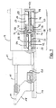
ねじ留め装置は、長手方向中心軸11を定めるとともに、長手方向中心軸11を中心に回転駆動装置12によって回転駆動可能であるねじ留め工具10を備える。トルク測定装置14が、ねじ留め工具10と回転駆動装置12との間に接続される。
The screwing device includes a screwing tool 10 that defines a longitudinal central axis 11 and can be rotationally driven by a
ねじ留め装置は、さらに、ねじ留め工具10の長手方向中心軸11と平行に延びるガイド16を備え、このガイド16上に供給ヘッド18が移動可能に支持されており、供給ヘッド18は、ねじ留めされる構成要素と接触する位置まで送出シリンダ20によってガイド16に沿って移動する。供給ヘッド18は、ねじ留め行程のための図示省略のねじを整列させて保持するように機能する。供給ヘッド18にねじを供給するためには、供給ヘッド18は、例えば供給ヘッド18に圧縮空気によってねじを打ち込む図示省略の自動供給装置に連結される。
The screwing device further comprises a
ねじ留め工具10を供給ヘッド18に保持されたねじと係合させるには、ねじ留め工具10をトルク測定装置14と共に休止位置と呼ぶこともできる図1に示す後方端位置から図1では左側である前方に押し出す。送り装置22が、この目的を果たし、ガイド16に移動可能に支持されたトルク測定装置14に作用する。
In order to engage the screwing tool 10 with the screw held in the
送り装置22は、動作ピストン28を有する空気圧式送りシリンダ24を備え、動作ピストン28は、ねじ留め工具10およびガイド16と平行に方向づけられているとともに、圧縮空気26によって作動可能で、かつ送りシリンダ24の長さによって予め定められる最大動作行程を実行可能である。動作ピストン28は、トルク測定装置14に接続されており、例えば、トルク測定装置14のハウジングに成形可能である。
The
動作ピストン28は、さらに中空のシリンダを形成し、図1では右側である後方から動作ピストン28内に延びるパイプ片30に移動可能に支持されている。パイプ片30と動作ピストン28とによって境界づけられる内部空間32は、作動油によって満たされており、シール34によって送りシリンダ24の空気空間36から密閉されている。
The
内部空間32は、第1の断面を有し、後方端で流体収容空間38に開口し、この流体収容空間38も同様に作動油によって満たされているとともに、内部空間32の断面よりも数倍大きい第2の断面を有する。流体収容空間38は、後方側で移動可能に支持されたリングピストン40によって境界づけられており、リングピストン40は、釣合いばね42によって、前方すなわち送りシリンダ24の方向に付勢されている。内部空間32および流体収容空間38は、合わせて閉じた油圧系を構成する。
The
パイプ片30と同軸に整列したプランジャ44が、リングピストン40を通って延びており、そのプロファイルは、パイプ片30に密に挿入することができるようにパイプ片30のプロファイルに一致するよう設けられており、パイプ片30の端部領域に設けられたシール46によって密封効果がさらに改善される。
A plunger 44 coaxially aligned with the
プランジャ44は、作動ピストン48の一部であり、作動ピストン48は、押込みシリンダ50内に移動可能に支持されているとともに、圧縮空気52によって作動可能である。押込みシリンダ50の空気空間54の流体収容空間38に対する密閉は、リングピストン40に嵌め込まれるシール56によってなされる。
The plunger 44 is a part of the
プランジャ44は、ここでは圧縮コイルばねである戻りばね58によって囲まれており、戻りばね58は、一方側ではリングピストン40の後面に支持されているとともに、他方側では作動ピストン48の前面に支持されており、リングピストン40と作動ピストン48とを離すように付勢する。代わりに、戻りばね58は、空気ばねの形態を有してもよい。
The plunger 44 is surrounded by a
構成要素30,58は、合わせて送り装置22の空気油圧式増圧器60を構成する。空気油圧式増圧器60の機能については以下に説明する。
The
ねじ留め工具10を図1に示す休止位置から供給ヘッド18に保持されたねじと係合する位置まで移動させるには、動作ピストン28が図1で左に移動するように送りシリンダ24に圧縮空気26を供給し、このときトルク測定装置14およびねじ留め工具10が前方に押される。ねじ留め工具10がねじと係合すると、ねじ留め工具10は、ねじがねじ留めされる構成要素に隣接するまで圧縮空気によって作動する送りシリンダ24によってさらに前方に押される。
In order to move the screwing tool 10 from the rest position shown in FIG. 1 to a position where it engages with a screw held in the
動作ピストン28の前方への移動により、内部空間32が増加し、作動油は、釣合いばね42が作用するリングピストン40によって流体収容空間38から内部空間32内に押し出される。
Due to the forward movement of the
圧縮空気26によって送りシリンダ24に加えられる力は、経済的なねじ留め行程で許容可能な時間内で、フロードリル加工によるねじ留め行程のための充分な熱をねじ留めされる構成要素に与えるのに充分でないため、ねじがねじ留めされる構成要素に接触するとすぐに増圧器60が作動される。
The force applied to the
これは、圧縮空気52を作動ピストン48に加え、これによりプランジャ44を前方に押すことによってなされる。プランジャ44がパイプ片30に挿入されるとすぐに、内部空間32は流体収容空間38に対して密閉され、作動油は内部空間32から流出することも内部空間32に流入することもできなくなる。作動ピストン48に圧縮空気52がさらに加えられると、今度は動作ピストン28によって第2の送り力がねじ留め工具10に加わり、第2の送り力は、圧縮空気26によって動作ピストン28に加わる第1の送り力よりもかなり大きい。作動ピストン48に作用する圧縮空気52が動作ピストン28に作用する圧縮空気26と同じ圧力であると仮定すると、第1の送り力に対する第2の送り力の比は、プランジャ44の断面に対する作動ピストン48の断面の比にほぼ対応する。
This is done by applying compressed air 52 to the working
圧縮空気52の圧力は、第2の送り力を調整するために、例えば、制御装置によって制御される空気圧比例弁によって制御できる。 The pressure of the compressed air 52 can be controlled by, for example, a pneumatic proportional valve that is controlled by a controller to adjust the second feed force.
増圧器60は、プロセス行程で許容可能な時間内に、フロードリル加工によるねじ留めのために充分に高い温度までねじ留めされる構成要素が加熱されるように、第2の送り力が充分に大きくなるよう寸法づけられる。
The
構成要素が充分なフロー可能状態に達すると、ねじがねじ留め工具10のさらなる送りによって構成要素に押し込まれる。構成要素が充分なフロー可能状態に達すると、圧縮空気52の供給を停止して増圧器60の動作を停止することができ、戻りばね58によってパイプ片30からプランジャ44が引き抜かれ、これにより、作動油が再び流体収納空間38から内部空間32に流出することが可能になり、ねじ留め行程の残りの段階におけるねじ留め工具10の送りは、動作ピストン28に圧縮空気26を与えることによって行われる。しかし、充分に高いストロークを実行できれば、全てのねじ留め行程を増圧器がオンになった状態で行うこともでき、この場合でも、増圧器60の圧力が調節された制御圧を利用して第2の送り力を調整できる。
When the component reaches a sufficient flowable state, the screw is pushed into the component by further feeding of the screwing tool 10. When the component reaches a sufficient flowable state, the supply of compressed air 52 can be stopped to stop the operation of the
最後に、図1に示す送りシリンダ24に対する増圧器60の構成は、概略的なものである。よって、増圧器60は、必ずしも送りシリンダ24と同軸に整列していなくてもよい。ねじ留め装置をより小型化するために、増圧器は、例えば、送りシリンダ24と平行にオフセットして配置されてもよく、反対方向に作用してもよい。後者の場合には、パイプ片30は、U字形の流体通路の一方のリムを構成することができ、増圧器60の作動時には、プランジャ44がU字形の流体通路の他方のリムに挿入される。
Finally, the configuration of the
10…ねじ留め工具
11…長手方向中心軸
12…回転駆動装置
14…トルク測定装置
16…ガイド
18…供給ヘッド
20…送出シリンダ
22…送り装置
24…送りシリンダ
26…圧縮空気
28…動作ピストン
30…パイプ片
32…内部空間
34…シール
36…空気空間
38…流体収容空間
40…リングピストン
42…釣合いばね
44…プランジャ
46…シール
48…作動ピストン
50…押込みシリンダ
52…圧縮空気
54…空気空間
56…シール
58…戻りばね
60…増圧器
DESCRIPTION OF SYMBOLS 10 ... Screwing tool 11 ... Longitudinal
Claims (11)
送り装置(22)は、ねじ留め行程において、第1の送り力よりも大きい第2の送り力をねじ留め工具(10)に加えることができる増圧器(60)を有することを特徴とするねじ留め装置。 In particular, a screwing device for automatically performing a screwing process comprising a screwing tool (10) and a feed device (22) having a pneumatic feed cylinder (24), the screwing tool (10). In the feed direction so that in the screwing stroke, the pneumatic feed cylinder (24) causes the first feed force to engage the screwing tool with the screw and to push the screw into the screwed component. In the screwing device that is movable,
The screw device (22) has a pressure intensifier (60) capable of applying a second feed force larger than the first feed force to the screwing tool (10) in a screwing process. Fastening device.
Applications Claiming Priority (3)
| Application Number | Priority Date | Filing Date | Title |
|---|---|---|---|
| DE102014106476.3 | 2014-05-08 | ||
| DE102014106476.3A DE102014106476A1 (en) | 2014-05-08 | 2014-05-08 | screwsystem |
| PCT/EP2015/059569 WO2015169693A1 (en) | 2014-05-08 | 2015-04-30 | Screw system |
Publications (1)
| Publication Number | Publication Date |
|---|---|
| JP2017514713A true JP2017514713A (en) | 2017-06-08 |
Family
ID=53015814
Family Applications (1)
| Application Number | Title | Priority Date | Filing Date |
|---|---|---|---|
| JP2016566896A Pending JP2017514713A (en) | 2014-05-08 | 2015-04-30 | Screwing device |
Country Status (6)
| Country | Link |
|---|---|
| US (1) | US20170072520A1 (en) |
| EP (1) | EP3126095A1 (en) |
| JP (1) | JP2017514713A (en) |
| CN (1) | CN106660180A (en) |
| DE (1) | DE102014106476A1 (en) |
| WO (1) | WO2015169693A1 (en) |
Families Citing this family (4)
| Publication number | Priority date | Publication date | Assignee | Title |
|---|---|---|---|---|
| CN109365834A (en) * | 2018-12-17 | 2019-02-22 | 苏州比雷艾斯电子科技有限公司 | A kind of complete lathe of precision control automated arm |
| DE102019120863A1 (en) * | 2019-08-01 | 2021-02-04 | Atlas Copco Ias Gmbh | Method for controlling a mechanical joining or forming process |
| DE202023101193U1 (en) | 2022-03-16 | 2023-06-05 | Valerio Farolfi | screw device |
| CN117300583A (en) * | 2023-11-30 | 2023-12-29 | 佛山市澳科自动化工程有限公司 | Automatic plug-beating device for metal pipe |
Citations (2)
| Publication number | Priority date | Publication date | Assignee | Title |
|---|---|---|---|---|
| JPS5548544A (en) * | 1978-09-29 | 1980-04-07 | Siemens Ag | Screw device of tapping screw |
| JPH07248001A (en) * | 1992-02-01 | 1995-09-26 | Tox Pressotechnik Gmbh | Hydraulic and pneumatic pressure system intensifier |
Family Cites Families (7)
| Publication number | Priority date | Publication date | Assignee | Title |
|---|---|---|---|---|
| DE4400709B4 (en) * | 1993-01-13 | 2005-06-23 | Denso Corp., Kariya | Screw fastening device |
| JP3793272B2 (en) * | 1996-02-09 | 2006-07-05 | 株式会社マキタ | Screw driving method and apparatus |
| JPH10109234A (en) * | 1996-09-30 | 1998-04-28 | Nitto Seiko Co Ltd | Automatic screw tightening machine |
| DE29711260U1 (en) * | 1997-06-27 | 1997-08-28 | Weber Schraubautomaten Gmbh | Stationary screwing machine |
| CN101852227A (en) * | 2010-06-22 | 2010-10-06 | 肖高富 | Powerful cylinder |
| CN202668041U (en) * | 2012-08-06 | 2013-01-16 | 胡伟 | Automatic screw fastening machine |
| CN103317337A (en) * | 2013-06-06 | 2013-09-25 | 苏州阿斯兰自动化科技有限公司 | Automatic screw locking mechanism |
-
2014
- 2014-05-08 DE DE102014106476.3A patent/DE102014106476A1/en not_active Withdrawn
-
2015
- 2015-04-30 WO PCT/EP2015/059569 patent/WO2015169693A1/en active Application Filing
- 2015-04-30 EP EP15719232.9A patent/EP3126095A1/en not_active Withdrawn
- 2015-04-30 JP JP2016566896A patent/JP2017514713A/en active Pending
- 2015-04-30 CN CN201580023868.6A patent/CN106660180A/en active Pending
- 2015-04-30 US US15/309,071 patent/US20170072520A1/en not_active Abandoned
Patent Citations (2)
| Publication number | Priority date | Publication date | Assignee | Title |
|---|---|---|---|---|
| JPS5548544A (en) * | 1978-09-29 | 1980-04-07 | Siemens Ag | Screw device of tapping screw |
| JPH07248001A (en) * | 1992-02-01 | 1995-09-26 | Tox Pressotechnik Gmbh | Hydraulic and pneumatic pressure system intensifier |
Also Published As
| Publication number | Publication date |
|---|---|
| WO2015169693A1 (en) | 2015-11-12 |
| CN106660180A (en) | 2017-05-10 |
| EP3126095A1 (en) | 2017-02-08 |
| US20170072520A1 (en) | 2017-03-16 |
| DE102014106476A1 (en) | 2015-11-12 |
Similar Documents
| Publication | Publication Date | Title |
|---|---|---|
| JP2017514713A (en) | Screwing device | |
| JP5100074B2 (en) | Pneumatic delivery system and method using linear actuation | |
| US10486172B2 (en) | Force amplifying driver system, jetting dispenser, and method of dispensing fluid | |
| JP2012162173A5 (en) | ||
| US11267116B2 (en) | Drive-in machine | |
| JP2009536296A (en) | Method for loading working cylinder, control unit for loading working cylinder, working cylinder and use thereof | |
| US20180272419A1 (en) | Multi-step joining device and joining method therefor | |
| JP2015112679A (en) | Driving tool | |
| US20140054053A1 (en) | Tool driving device, tool driving method, and tool feeding mechanism for tool driving device | |
| US20090004027A1 (en) | Ventilation of an Operating Element | |
| JP2020192630A (en) | Drive system for chuck device and control method for the same | |
| KR102406100B1 (en) | Control Methods for Impact Handheld Power Tools | |
| KR20150097517A (en) | Impulse wrench with push start feature | |
| CN106979372B (en) | Flow control valve with motion conversion device | |
| JP2004503702A (en) | Hydraulic intensifier | |
| US3064626A (en) | Power-driven stapling machine | |
| US1847889A (en) | Riveter | |
| JP6199912B2 (en) | Control device for meshing engagement mechanism | |
| WO2007091448A1 (en) | Pneumatic reciprocating tool | |
| JP6003707B2 (en) | Coating device | |
| JP4241407B2 (en) | Intermediate position stop cylinder | |
| WO2004072487A1 (en) | Control valve for a pneumatic cylinder | |
| JP2019100370A5 (en) | ||
| WO2016178587A1 (en) | A pneumatic or hydraulic mechanism | |
| KR20210030287A (en) | Lubrication pump device |
Legal Events
| Date | Code | Title | Description |
|---|---|---|---|
| A621 | Written request for application examination |
Free format text: JAPANESE INTERMEDIATE CODE: A621 Effective date: 20171127 |
|
| A131 | Notification of reasons for refusal |
Free format text: JAPANESE INTERMEDIATE CODE: A131 Effective date: 20181009 |
|
| A601 | Written request for extension of time |
Free format text: JAPANESE INTERMEDIATE CODE: A601 Effective date: 20190108 |
|
| A601 | Written request for extension of time |
Free format text: JAPANESE INTERMEDIATE CODE: A601 Effective date: 20190308 |
|
| A02 | Decision of refusal |
Free format text: JAPANESE INTERMEDIATE CODE: A02 Effective date: 20190604 |