JP2017514638A - Portable sterilizer and method of using the same - Google Patents
Portable sterilizer and method of using the same Download PDFInfo
- Publication number
- JP2017514638A JP2017514638A JP2016575606A JP2016575606A JP2017514638A JP 2017514638 A JP2017514638 A JP 2017514638A JP 2016575606 A JP2016575606 A JP 2016575606A JP 2016575606 A JP2016575606 A JP 2016575606A JP 2017514638 A JP2017514638 A JP 2017514638A
- Authority
- JP
- Japan
- Prior art keywords
- panel
- cabinet
- sterilization
- filter
- bottom panel
- Prior art date
- Legal status (The legal status is an assumption and is not a legal conclusion. Google has not performed a legal analysis and makes no representation as to the accuracy of the status listed.)
- Pending
Links
- 238000000034 method Methods 0.000 title claims description 46
- 230000001954 sterilising effect Effects 0.000 claims abstract description 327
- 238000004659 sterilization and disinfection Methods 0.000 claims abstract description 318
- 238000003032 molecular docking Methods 0.000 claims description 30
- 239000000463 material Substances 0.000 claims description 14
- 230000007246 mechanism Effects 0.000 claims description 12
- 238000009434 installation Methods 0.000 claims description 11
- 238000004519 manufacturing process Methods 0.000 claims description 4
- 238000010586 diagram Methods 0.000 description 32
- 230000008569 process Effects 0.000 description 15
- 238000003860 storage Methods 0.000 description 10
- 230000035939 shock Effects 0.000 description 7
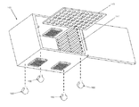
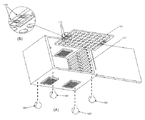
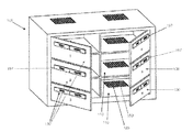
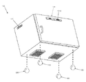
- XLYOFNOQVPJJNP-UHFFFAOYSA-N water Substances O XLYOFNOQVPJJNP-UHFFFAOYSA-N 0.000 description 7
- 239000000356 contaminant Substances 0.000 description 5
- 230000008901 benefit Effects 0.000 description 4
- 230000008859 change Effects 0.000 description 4
- 239000000725 suspension Substances 0.000 description 4
- 230000005484 gravity Effects 0.000 description 3
- 230000006872 improvement Effects 0.000 description 3
- 230000036512 infertility Effects 0.000 description 3
- 239000010935 stainless steel Substances 0.000 description 3
- 229910001220 stainless steel Inorganic materials 0.000 description 3
- XAGFODPZIPBFFR-UHFFFAOYSA-N aluminium Chemical compound [Al] XAGFODPZIPBFFR-UHFFFAOYSA-N 0.000 description 2
- 229910052782 aluminium Inorganic materials 0.000 description 2
- 230000006870 function Effects 0.000 description 2
- 230000036541 health Effects 0.000 description 2
- 239000007788 liquid Substances 0.000 description 2
- KQAOIKIZSJJTII-UHFFFAOYSA-N p-mercuribenzenesulfonic acid Chemical compound OS(=O)(=O)C1=CC=C([Hg])C=C1 KQAOIKIZSJJTII-UHFFFAOYSA-N 0.000 description 2
- 238000004806 packaging method and process Methods 0.000 description 2
- 229920000642 polymer Polymers 0.000 description 2
- 239000000565 sealant Substances 0.000 description 2
- 238000007789 sealing Methods 0.000 description 2
- 238000012414 sterilization procedure Methods 0.000 description 2
- 239000012780 transparent material Substances 0.000 description 2
- 238000011282 treatment Methods 0.000 description 2
- 238000009423 ventilation Methods 0.000 description 2
- OKTJSMMVPCPJKN-UHFFFAOYSA-N Carbon Chemical compound [C] OKTJSMMVPCPJKN-UHFFFAOYSA-N 0.000 description 1
- 241000282414 Homo sapiens Species 0.000 description 1
- 239000006096 absorbing agent Substances 0.000 description 1
- 238000010521 absorption reaction Methods 0.000 description 1
- 230000009471 action Effects 0.000 description 1
- 230000002730 additional effect Effects 0.000 description 1
- 238000004026 adhesive bonding Methods 0.000 description 1
- 238000002048 anodisation reaction Methods 0.000 description 1
- 230000005540 biological transmission Effects 0.000 description 1
- 229910052799 carbon Inorganic materials 0.000 description 1
- 230000000295 complement effect Effects 0.000 description 1
- 230000006835 compression Effects 0.000 description 1
- 238000007906 compression Methods 0.000 description 1
- 230000001010 compromised effect Effects 0.000 description 1
- 239000004035 construction material Substances 0.000 description 1
- 238000011109 contamination Methods 0.000 description 1
- 238000002788 crimping Methods 0.000 description 1
- 238000006073 displacement reaction Methods 0.000 description 1
- 238000001035 drying Methods 0.000 description 1
- 230000000694 effects Effects 0.000 description 1
- 238000005516 engineering process Methods 0.000 description 1
- 238000001704 evaporation Methods 0.000 description 1
- 230000008020 evaporation Effects 0.000 description 1
- 239000011521 glass Substances 0.000 description 1
- 230000013011 mating Effects 0.000 description 1
- 239000012569 microbial contaminant Substances 0.000 description 1
- 230000000813 microbial effect Effects 0.000 description 1
- 229920000515 polycarbonate Polymers 0.000 description 1
- 239000004417 polycarbonate Substances 0.000 description 1
- 238000003825 pressing Methods 0.000 description 1
- 230000006903 response to temperature Effects 0.000 description 1
- 238000009958 sewing Methods 0.000 description 1
- 229910001285 shape-memory alloy Inorganic materials 0.000 description 1
- 238000004513 sizing Methods 0.000 description 1
- 239000004984 smart glass Substances 0.000 description 1
- 238000000638 solvent extraction Methods 0.000 description 1
- 238000012360 testing method Methods 0.000 description 1
- 230000037303 wrinkles Effects 0.000 description 1
Images
Classifications
-
- A—HUMAN NECESSITIES
- A61—MEDICAL OR VETERINARY SCIENCE; HYGIENE
- A61L—METHODS OR APPARATUS FOR STERILISING MATERIALS OR OBJECTS IN GENERAL; DISINFECTION, STERILISATION OR DEODORISATION OF AIR; CHEMICAL ASPECTS OF BANDAGES, DRESSINGS, ABSORBENT PADS OR SURGICAL ARTICLES; MATERIALS FOR BANDAGES, DRESSINGS, ABSORBENT PADS OR SURGICAL ARTICLES
- A61L2/00—Methods or apparatus for disinfecting or sterilising materials or objects other than foodstuffs or contact lenses; Accessories therefor
- A61L2/02—Methods or apparatus for disinfecting or sterilising materials or objects other than foodstuffs or contact lenses; Accessories therefor using physical phenomena
- A61L2/04—Heat
- A61L2/06—Hot gas
- A61L2/07—Steam
-
- A—HUMAN NECESSITIES
- A47—FURNITURE; DOMESTIC ARTICLES OR APPLIANCES; COFFEE MILLS; SPICE MILLS; SUCTION CLEANERS IN GENERAL
- A47B—TABLES; DESKS; OFFICE FURNITURE; CABINETS; DRAWERS; GENERAL DETAILS OF FURNITURE
- A47B57/00—Cabinets, racks or shelf units, characterised by features for adjusting shelves or partitions
- A47B57/06—Cabinets, racks or shelf units, characterised by features for adjusting shelves or partitions with means for adjusting the height of the shelves
- A47B57/20—Cabinets, racks or shelf units, characterised by features for adjusting shelves or partitions with means for adjusting the height of the shelves consisting of tongues, pins or similar projecting means coacting with openings
-
- A—HUMAN NECESSITIES
- A47—FURNITURE; DOMESTIC ARTICLES OR APPLIANCES; COFFEE MILLS; SPICE MILLS; SUCTION CLEANERS IN GENERAL
- A47B—TABLES; DESKS; OFFICE FURNITURE; CABINETS; DRAWERS; GENERAL DETAILS OF FURNITURE
- A47B81/00—Cabinets or racks specially adapted for other particular purposes, e.g. for storing guns or skis
-
- A—HUMAN NECESSITIES
- A47—FURNITURE; DOMESTIC ARTICLES OR APPLIANCES; COFFEE MILLS; SPICE MILLS; SUCTION CLEANERS IN GENERAL
- A47B—TABLES; DESKS; OFFICE FURNITURE; CABINETS; DRAWERS; GENERAL DETAILS OF FURNITURE
- A47B91/00—Feet for furniture in general
- A47B91/04—Elastic supports
-
- A—HUMAN NECESSITIES
- A47—FURNITURE; DOMESTIC ARTICLES OR APPLIANCES; COFFEE MILLS; SPICE MILLS; SUCTION CLEANERS IN GENERAL
- A47B—TABLES; DESKS; OFFICE FURNITURE; CABINETS; DRAWERS; GENERAL DETAILS OF FURNITURE
- A47B91/00—Feet for furniture in general
- A47B91/16—Self-levelling legs
-
- A—HUMAN NECESSITIES
- A61—MEDICAL OR VETERINARY SCIENCE; HYGIENE
- A61B—DIAGNOSIS; SURGERY; IDENTIFICATION
- A61B50/00—Containers, covers, furniture or holders specially adapted for surgical or diagnostic appliances or instruments, e.g. sterile covers
-
- A—HUMAN NECESSITIES
- A61—MEDICAL OR VETERINARY SCIENCE; HYGIENE
- A61B—DIAGNOSIS; SURGERY; IDENTIFICATION
- A61B50/00—Containers, covers, furniture or holders specially adapted for surgical or diagnostic appliances or instruments, e.g. sterile covers
- A61B50/10—Furniture specially adapted for surgical or diagnostic appliances or instruments
- A61B50/13—Trolleys, e.g. carts
-
- A—HUMAN NECESSITIES
- A61—MEDICAL OR VETERINARY SCIENCE; HYGIENE
- A61B—DIAGNOSIS; SURGERY; IDENTIFICATION
- A61B50/00—Containers, covers, furniture or holders specially adapted for surgical or diagnostic appliances or instruments, e.g. sterile covers
- A61B50/20—Holders specially adapted for surgical or diagnostic appliances or instruments
- A61B50/22—Racks
-
- A—HUMAN NECESSITIES
- A61—MEDICAL OR VETERINARY SCIENCE; HYGIENE
- A61B—DIAGNOSIS; SURGERY; IDENTIFICATION
- A61B50/00—Containers, covers, furniture or holders specially adapted for surgical or diagnostic appliances or instruments, e.g. sterile covers
- A61B50/30—Containers specially adapted for packaging, protecting, dispensing, collecting or disposing of surgical or diagnostic appliances or instruments
- A61B50/33—Trays
-
- A—HUMAN NECESSITIES
- A61—MEDICAL OR VETERINARY SCIENCE; HYGIENE
- A61B—DIAGNOSIS; SURGERY; IDENTIFICATION
- A61B50/00—Containers, covers, furniture or holders specially adapted for surgical or diagnostic appliances or instruments, e.g. sterile covers
- A61B50/30—Containers specially adapted for packaging, protecting, dispensing, collecting or disposing of surgical or diagnostic appliances or instruments
- A61B50/34—Baskets
-
- A—HUMAN NECESSITIES
- A61—MEDICAL OR VETERINARY SCIENCE; HYGIENE
- A61L—METHODS OR APPARATUS FOR STERILISING MATERIALS OR OBJECTS IN GENERAL; DISINFECTION, STERILISATION OR DEODORISATION OF AIR; CHEMICAL ASPECTS OF BANDAGES, DRESSINGS, ABSORBENT PADS OR SURGICAL ARTICLES; MATERIALS FOR BANDAGES, DRESSINGS, ABSORBENT PADS OR SURGICAL ARTICLES
- A61L2/00—Methods or apparatus for disinfecting or sterilising materials or objects other than foodstuffs or contact lenses; Accessories therefor
- A61L2/24—Apparatus using programmed or automatic operation
-
- A—HUMAN NECESSITIES
- A61—MEDICAL OR VETERINARY SCIENCE; HYGIENE
- A61L—METHODS OR APPARATUS FOR STERILISING MATERIALS OR OBJECTS IN GENERAL; DISINFECTION, STERILISATION OR DEODORISATION OF AIR; CHEMICAL ASPECTS OF BANDAGES, DRESSINGS, ABSORBENT PADS OR SURGICAL ARTICLES; MATERIALS FOR BANDAGES, DRESSINGS, ABSORBENT PADS OR SURGICAL ARTICLES
- A61L2/00—Methods or apparatus for disinfecting or sterilising materials or objects other than foodstuffs or contact lenses; Accessories therefor
- A61L2/26—Accessories or devices or components used for biocidal treatment
-
- A—HUMAN NECESSITIES
- A61—MEDICAL OR VETERINARY SCIENCE; HYGIENE
- A61L—METHODS OR APPARATUS FOR STERILISING MATERIALS OR OBJECTS IN GENERAL; DISINFECTION, STERILISATION OR DEODORISATION OF AIR; CHEMICAL ASPECTS OF BANDAGES, DRESSINGS, ABSORBENT PADS OR SURGICAL ARTICLES; MATERIALS FOR BANDAGES, DRESSINGS, ABSORBENT PADS OR SURGICAL ARTICLES
- A61L9/00—Disinfection, sterilisation or deodorisation of air
-
- B—PERFORMING OPERATIONS; TRANSPORTING
- B01—PHYSICAL OR CHEMICAL PROCESSES OR APPARATUS IN GENERAL
- B01D—SEPARATION
- B01D46/00—Filters or filtering processes specially modified for separating dispersed particles from gases or vapours
- B01D46/0002—Casings; Housings; Frame constructions
- B01D46/0005—Mounting of filtering elements within casings, housings or frames
-
- B—PERFORMING OPERATIONS; TRANSPORTING
- B01—PHYSICAL OR CHEMICAL PROCESSES OR APPARATUS IN GENERAL
- B01D—SEPARATION
- B01D46/00—Filters or filtering processes specially modified for separating dispersed particles from gases or vapours
- B01D46/0084—Filters or filtering processes specially modified for separating dispersed particles from gases or vapours provided with safety means
- B01D46/0086—Filter condition indicators
-
- B—PERFORMING OPERATIONS; TRANSPORTING
- B60—VEHICLES IN GENERAL
- B60B—VEHICLE WHEELS; CASTORS; AXLES FOR WHEELS OR CASTORS; INCREASING WHEEL ADHESION
- B60B33/00—Castors in general; Anti-clogging castors
-
- A—HUMAN NECESSITIES
- A61—MEDICAL OR VETERINARY SCIENCE; HYGIENE
- A61B—DIAGNOSIS; SURGERY; IDENTIFICATION
- A61B50/00—Containers, covers, furniture or holders specially adapted for surgical or diagnostic appliances or instruments, e.g. sterile covers
- A61B50/10—Furniture specially adapted for surgical or diagnostic appliances or instruments
- A61B2050/105—Cabinets
-
- A—HUMAN NECESSITIES
- A61—MEDICAL OR VETERINARY SCIENCE; HYGIENE
- A61L—METHODS OR APPARATUS FOR STERILISING MATERIALS OR OBJECTS IN GENERAL; DISINFECTION, STERILISATION OR DEODORISATION OF AIR; CHEMICAL ASPECTS OF BANDAGES, DRESSINGS, ABSORBENT PADS OR SURGICAL ARTICLES; MATERIALS FOR BANDAGES, DRESSINGS, ABSORBENT PADS OR SURGICAL ARTICLES
- A61L2202/00—Aspects relating to methods or apparatus for disinfecting or sterilising materials or objects
- A61L2202/10—Apparatus features
- A61L2202/12—Apparatus for isolating biocidal substances from the environment
- A61L2202/122—Chambers for sterilisation
-
- A—HUMAN NECESSITIES
- A61—MEDICAL OR VETERINARY SCIENCE; HYGIENE
- A61L—METHODS OR APPARATUS FOR STERILISING MATERIALS OR OBJECTS IN GENERAL; DISINFECTION, STERILISATION OR DEODORISATION OF AIR; CHEMICAL ASPECTS OF BANDAGES, DRESSINGS, ABSORBENT PADS OR SURGICAL ARTICLES; MATERIALS FOR BANDAGES, DRESSINGS, ABSORBENT PADS OR SURGICAL ARTICLES
- A61L2202/00—Aspects relating to methods or apparatus for disinfecting or sterilising materials or objects
- A61L2202/10—Apparatus features
- A61L2202/14—Means for controlling sterilisation processes, data processing, presentation and storage means, e.g. sensors, controllers, programs
-
- A—HUMAN NECESSITIES
- A61—MEDICAL OR VETERINARY SCIENCE; HYGIENE
- A61L—METHODS OR APPARATUS FOR STERILISING MATERIALS OR OBJECTS IN GENERAL; DISINFECTION, STERILISATION OR DEODORISATION OF AIR; CHEMICAL ASPECTS OF BANDAGES, DRESSINGS, ABSORBENT PADS OR SURGICAL ARTICLES; MATERIALS FOR BANDAGES, DRESSINGS, ABSORBENT PADS OR SURGICAL ARTICLES
- A61L2202/00—Aspects relating to methods or apparatus for disinfecting or sterilising materials or objects
- A61L2202/10—Apparatus features
- A61L2202/16—Mobile applications, e.g. portable devices, trailers, devices mounted on vehicles
-
- A—HUMAN NECESSITIES
- A61—MEDICAL OR VETERINARY SCIENCE; HYGIENE
- A61L—METHODS OR APPARATUS FOR STERILISING MATERIALS OR OBJECTS IN GENERAL; DISINFECTION, STERILISATION OR DEODORISATION OF AIR; CHEMICAL ASPECTS OF BANDAGES, DRESSINGS, ABSORBENT PADS OR SURGICAL ARTICLES; MATERIALS FOR BANDAGES, DRESSINGS, ABSORBENT PADS OR SURGICAL ARTICLES
- A61L2202/00—Aspects relating to methods or apparatus for disinfecting or sterilising materials or objects
- A61L2202/10—Apparatus features
- A61L2202/18—Aseptic storing means
- A61L2202/182—Rigid packaging means
-
- A—HUMAN NECESSITIES
- A61—MEDICAL OR VETERINARY SCIENCE; HYGIENE
- A61L—METHODS OR APPARATUS FOR STERILISING MATERIALS OR OBJECTS IN GENERAL; DISINFECTION, STERILISATION OR DEODORISATION OF AIR; CHEMICAL ASPECTS OF BANDAGES, DRESSINGS, ABSORBENT PADS OR SURGICAL ARTICLES; MATERIALS FOR BANDAGES, DRESSINGS, ABSORBENT PADS OR SURGICAL ARTICLES
- A61L2202/00—Aspects relating to methods or apparatus for disinfecting or sterilising materials or objects
- A61L2202/20—Targets to be treated
- A61L2202/24—Medical instruments, e.g. endoscopes, catheters, sharps
-
- B—PERFORMING OPERATIONS; TRANSPORTING
- B62—LAND VEHICLES FOR TRAVELLING OTHERWISE THAN ON RAILS
- B62B—HAND-PROPELLED VEHICLES, e.g. HAND CARTS OR PERAMBULATORS; SLEDGES
- B62B3/00—Hand carts having more than one axis carrying transport wheels; Steering devices therefor; Equipment therefor
-
- B—PERFORMING OPERATIONS; TRANSPORTING
- B62—LAND VEHICLES FOR TRAVELLING OTHERWISE THAN ON RAILS
- B62B—HAND-PROPELLED VEHICLES, e.g. HAND CARTS OR PERAMBULATORS; SLEDGES
- B62B3/00—Hand carts having more than one axis carrying transport wheels; Steering devices therefor; Equipment therefor
- B62B3/02—Hand carts having more than one axis carrying transport wheels; Steering devices therefor; Equipment therefor involving parts being adjustable, collapsible, attachable, detachable or convertible
-
- Y—GENERAL TAGGING OF NEW TECHNOLOGICAL DEVELOPMENTS; GENERAL TAGGING OF CROSS-SECTIONAL TECHNOLOGIES SPANNING OVER SEVERAL SECTIONS OF THE IPC; TECHNICAL SUBJECTS COVERED BY FORMER USPC CROSS-REFERENCE ART COLLECTIONS [XRACs] AND DIGESTS
- Y10—TECHNICAL SUBJECTS COVERED BY FORMER USPC
- Y10T—TECHNICAL SUBJECTS COVERED BY FORMER US CLASSIFICATION
- Y10T29/00—Metal working
- Y10T29/49—Method of mechanical manufacture
- Y10T29/49826—Assembling or joining
- Y10T29/49828—Progressively advancing of work assembly station or assembled portion of work
Landscapes
- Health & Medical Sciences (AREA)
- Life Sciences & Earth Sciences (AREA)
- Surgery (AREA)
- Animal Behavior & Ethology (AREA)
- General Health & Medical Sciences (AREA)
- Public Health (AREA)
- Veterinary Medicine (AREA)
- Engineering & Computer Science (AREA)
- Biomedical Technology (AREA)
- Nuclear Medicine, Radiotherapy & Molecular Imaging (AREA)
- Heart & Thoracic Surgery (AREA)
- Medical Informatics (AREA)
- Molecular Biology (AREA)
- Epidemiology (AREA)
- Chemical & Material Sciences (AREA)
- Chemical Kinetics & Catalysis (AREA)
- Mechanical Engineering (AREA)
- Apparatus For Disinfection Or Sterilisation (AREA)
- Handcart (AREA)
- Accommodation For Nursing Or Treatment Tables (AREA)
Abstract
携帯用滅菌システムであって、滅菌キャビネットを備える。滅菌キャビネットは、内部チャンバを規定する底部パネル、上部パネル、2つの側方パネル、背面パネル、及びドアと、底部パネルに搭載された複数のキャスタ又はホイールとを備える。複数のキャスタ又はホイールは、各々、キャスタブラケット又はホイールブラケットによって底部パネルに搭載される。キャスタブラケット又はホイールブラケットは横方向突起を備える。A portable sterilization system comprising a sterilization cabinet. The sterilization cabinet comprises a bottom panel defining an internal chamber, a top panel, two side panels, a back panel, and a door, and a plurality of casters or wheels mounted on the bottom panel. The plurality of casters or wheels are each mounted on the bottom panel by caster brackets or wheel brackets. The caster bracket or wheel bracket includes a lateral projection.
Description
(関連出願)本特許出願は、
(1)PMBS,LLC及びMichele Mauzerallらにより2014年3月10日に出願された、携帯用滅菌装置及びその使用方法(代理人整理番号:KEENAN−1PROV)に関する係属中の先行米国仮特許出願シリアル番号61/950,502号、及び
(Related application)
(1) Pending US provisional patent applications serialized on PMBS, LLC and Michelle Mauserall et al. No. 61/950, 502, and
(2)PMBS,LLC及びMichele Mauzerallらにより2014年9月22日に出願された、携帯用滅菌装置及びその使用方法(代理人整理番号:KEENAN−2PROV)に関する係属中の先行米国仮特許出願シリアル番号62/053,338号
の利益を主張するものである。
以上2つの特許出願を参照としてここに組み込む。
(2) A pending prior US provisional patent application serialized on PMBS, LLC and Michelle Mauserall et al. No. 62 / 053,338 claims the benefit.
These two patent applications are incorporated herein by reference.
本発明は、医療機器及び処置全般に係り、特に、医療器具及び/又は装置の滅菌と、使用予定時まで滅菌状態を維持するための滅菌装置及び処置に係る。 The present invention relates generally to medical devices and procedures, and more particularly to sterilization of medical instruments and / or devices and sterilization devices and procedures for maintaining sterility until the scheduled use.
多くの医療処置において、その実施には滅菌済みの器具及び/又は装置を使用する必要がある。このように医療処置のために滅菌済みの器具及び/又は装置を提供することは、現在のところ、特に多くの人材と専用装備等を要する、時間の掛かる高価な業務である。 Many medical procedures require the use of sterilized instruments and / or devices for their implementation. Providing sterilized instruments and / or devices for medical procedures in this manner is currently a time consuming and expensive task that requires a large number of personnel and specialized equipment.
過去には、病院(及び/又は手術センター等のその他の手術設備)では、器具トレイ滅菌システムを使用したが、これは所定の処置を行うのに必要な器具及び/又は装置を収容したトレイを特別に製造された使い捨て包装で包装するというものであった。包装されたトレイには、その後、メーカーの推奨に従ってオートクレーブ処理が施された。その後、トレイをオートクレーブから取り出し、冷却し、処置のために内容物が必要とされるまで保管した。器具及び/又は装置の使用に先立って、内容物を非滅菌状態とし得る損傷が発生していないことを保証すべく包装の検査を行うのに追加の人材を要するものであった。 In the past, hospitals (and / or other surgical equipment such as surgical centers) used instrument tray sterilization systems that do not contain trays that contain the instruments and / or equipment needed to perform a given procedure. It was to wrap with a specially manufactured disposable packaging. The packaged tray was then autoclaved according to the manufacturer's recommendations. The tray was then removed from the autoclave, cooled, and stored until the contents were needed for treatment. Prior to use of the instrument and / or apparatus, additional personnel were required to inspect the packaging to ensure that no damage has occurred that could render the contents non-sterile.
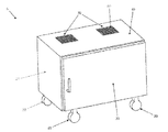
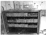
上述の問題点にある程度対応するため、携帯用滅菌キャビネットが導入されている。図1〜3は、一例としての従来の携帯用滅菌キャビネット5を示している。滅菌キャビネット5は、通常、キャビネット底部25、キャビネット側壁26、キャビネット背面壁27、及びキャビネット上部40に包囲された矩形上内部チャンバ10(図2)を備える。キャビネット5は、さらに、キャビネット5の内部チャンバ10を選択的に開閉する1つ以上のドア30を備えてもよい。例えば、図2を参照すると、1つのドア30が開放位置にあるキャビネット5が示されており、図3を参照すると、2つのドア30が閉鎖位置にあるキャビネット5が示されている。キャビネット5は、さらに、ドアが閉鎖された際、キャビネット5を封止するため、キャビネット5のドアとフレームとの境界にガスケット(図示せず)を備えてもよい。
キャビネット5の内部チャンバ10は、チャンバ10内の手術用トレイを支持する棚45も備えることが好ましい。
Portable sterilization cabinets have been introduced to address some of the above problems. 1-3 show a conventional
The internal chamber 10 of the
さらにキャビネット5は、キャビネット上部40及び/又はキャビネット底部25に形成された1つ以上の通気口35を備える。通気口35は、フィルタ50によって被覆され、フィルタカバー55が通気口35に対向する位置にフィルタ50を保持する。
The
キャビネット5をオートクレーブ内、又は手術室、又は保管室に移動するため、キャビネット5は、キャビネット底部25に直接搭載されたホイール20を備える。
使用中、医療器具及び/又は器具トレイは棚45上に配置され、棚はキャビネット5の内部チャンバ10内に搭載される。
In order to move the
During use, medical instruments and / or instrument trays are placed on
或いは、棚45がキャビネット5内に搭載された後、医療器具及び/又は器具トレイが棚45上に配置されてもよい。その後、キャビネット5全体をオートクレーブ内に車輪移動し、次いでオートクレーブを始動する。オートクレーブによって生成された熱気及び蒸気は、通気口35を通ってキャビネット5の内部チャンバ10内を通過することができ、これによってキャビネット5及びその内容物を滅菌する。オートクレーブサイクルが終わると、キャビネット5をオートクレーブから取り出し、冷却した後、保管スペースに移動するか、医療処置関連で使用するため、手術室又はその他のスペースに直接移動する。滅菌済みのキャビネット5は、内容物が医療処置に必要となる時まで閉鎖されたままとする。キャビネット5が閉鎖されている限り、フィルタ50が通気口35を通ってキャビネット内部に汚染物が侵入することを防ぐため、内容物は滅菌状態に維持される。
Alternatively, medical instruments and / or instrument trays may be placed on the
携帯用滅菌キャビネットの導入により、病院での滅菌処置を著しく減少させ、効率を向上したものの、いくつかの問題点が残っている。例えば、従来の既存のキャビネットは、オートクレーブ内への出し入れが困難であり、病院(例えば、保管エリア又は手術室)での取り扱いが困難となる可能性がある。 Although the introduction of portable sterilization cabinets has significantly reduced hospital sterilization procedures and improved efficiency, several problems remain. For example, conventional existing cabinets are difficult to put in and out of an autoclave and can be difficult to handle in a hospital (eg, storage area or operating room).
さらに既存のキャビネット5は、多くの場合、一層混雑した、スペースの貴重となる病院内では保管が困難となる可能性がある。また、ドアの旋回半径が収まるスペースがなければならないため、既存のキャビネットを所望の時に開放するには、既存のキャビネットの設置面積が著しく広くなる可能性がある。
Furthermore, existing
さらに既存のキャビネットは、時として、オートクレーブサイクルの終了時、キャビネットの底部に水が溜まる可能性がある。これは、いくつかの理由により望ましくない。1つの理由として、水は、汚染物を(例えば、吸い上げ作用により、キャビネット底部25のフィルタ50を介して、内部チャンバ10内に)「引き寄せ」得る導管として機能し得ることが挙げられる。
Furthermore, existing cabinets can sometimes accumulate water at the bottom of the cabinet at the end of the autoclave cycle. This is undesirable for several reasons. One reason is that water can serve as a conduit that can “pull” contaminants (eg, through the
また医療従事者が、既存のキャビネット又はその内容物の現在のステータスを視覚的に査定することは困難でもあり得る。例えば、医療従事者には、オートクレーブ済みの既存のキャビネットが依然として熱く、取り扱いができないのか否か、又は安全に取り扱いのできる温度まで冷却されたのか否かを把握するのは困難である。同様に、医療従事者には、キャビネットを開放して滅菌フィールドを汚すことなく、既存のキャビネットの内容物のステータス及び/又は目録を視覚的に査定又は確認することは困難であり得る。 It can also be difficult for medical personnel to visually assess the current status of an existing cabinet or its contents. For example, it is difficult for a health care professional to know whether an existing autoclaved cabinet is still hot and cannot be handled or has been cooled to a temperature that can be safely handled. Similarly, it may be difficult for a health care professional to visually assess or confirm the status and / or inventory of the contents of an existing cabinet without opening the cabinet and contaminating the sterilization field.
既存のキャビネットの他の問題点として、内部への棚の搭載が厄介であること、キャビネット内でより小さな領域を十分に分離することができないこと、フィルタへのアクセス及び変更が困難であること等が挙げられる。
既存のキャビネットのさらに他の欠点については、当業者に既知である。
Other problems with existing cabinets include the difficulty of mounting shelves inside, the inability to adequately separate smaller areas within the cabinet, and the difficulty of accessing and changing filters. Is mentioned.
Still other disadvantages of existing cabinets are known to those skilled in the art.
従って、医療器具及び装置を滅菌し、使用前まで滅菌済みの医療器具及び装置を滅菌状態で保管し、医療処置の実施される場所まで滅菌済みの医療器具及び装置を移動する、従来の不都合の1つ以上を克服した新規の改良携帯用滅菌装置及び方法が必要とされている。 Therefore, the conventional disadvantages of sterilizing medical instruments and devices, storing sterilized medical instruments and devices before use, and moving the sterilized medical instruments and devices to the place where medical procedures are performed There is a need for new and improved portable sterilization devices and methods that overcome one or more.
本発明は、医療器具及び装置を滅菌し、滅菌済みの医療器具及び装置を使用時まで滅菌状態で保管した後、滅菌済みの医療器具及び装置を医療処置の実施される場所まで搬送する新規の改良携帯用滅菌装置及び方法を提供するものである。 The present invention provides a novel method for sterilizing medical instruments and devices, storing sterilized medical instruments and devices in a sterile state until use, and then transporting the sterilized medical instruments and devices to a place where medical procedures are performed. An improved portable sterilization apparatus and method is provided.
本発明の好適な一様態によると、携帯用滅菌システムであって、滅菌キャビネットを備え、前記滅菌キャビネットは、内部チャンバを規定する、底部パネルと、上部パネルと、2つの側方パネルと、背面パネルと、ドアと、各々、横方向突起を備えたキャスタブラケット又はホイールブラケットにより、前記底部パネルに搭載された複数のキャスタ又はホイールと、前記底部パネル、前記上部パネル、及び前記2つの側方パネルの少なくとも1つに形成された穿孔部と、前記穿孔を被覆する少なくとも1つのフィルタと、その長手方向に沿って延びて横方向突起を各々備える一対の移動カート進路を備えた、滅菌キャビネットを受容する前記上方プラットフォームを備える移動カートと、前記上方プラットフォームを支持し、ホイールを受容する下方支持構造とを備え、前記滅菌キャビネットは、前記キャスタブラケット又はホイールブラケットの前記横方向突起が前記移動カート進路の前記横方向突起に係合することにより、前記移動カートに対して前記滅菌キャビネットが左右移動または上下移動をしないように前記移動カート上に受容される携帯用滅菌システムを提供する。 According to a preferred aspect of the present invention, there is a portable sterilization system comprising a sterilization cabinet, said sterilization cabinet defining an internal chamber, a bottom panel, a top panel, two side panels, and a back surface. A plurality of casters or wheels mounted on the bottom panel, a bottom panel, the top panel, and the two side panels by a panel, a door, and a caster bracket or a wheel bracket each having a lateral protrusion. Receiving a sterilization cabinet comprising a perforation formed in at least one of the first and second filters, at least one filter covering the perforation, and a pair of moving cart paths each extending along a longitudinal direction thereof and having lateral protrusions. A mobile cart with the upper platform supporting the upper platform and receiving a wheel The sterilization cabinet with respect to the moving cart by engaging the lateral protrusions of the caster bracket or wheel bracket with the lateral protrusions of the moving cart path. Provides a portable sterilization system that is received on the mobile cart so that it does not move from side to side or up and down.
本発明の他の好適な一様態によると、滅菌対象装備を保持し、且つ/又は、滅菌済み装備を保管する装置であって、内部チャンバを規定する底部パネル、上部パネル、2つの側方パネル、背面パネル、及びドアと、前記底部パネルに搭載された複数のキャスタ又はホイールと、前記底部パネル、前記上部パネル、前記2つの側方パネル、及び前記背面パネルの少なくとも1つに形成された複数の穿孔部と、前記複数の穿孔部を被覆する少なくとも1つのフィルタと、前記底部パネルに形成された排出口とを備える装置を提供する。 According to another preferred embodiment of the present invention, an apparatus for holding equipment to be sterilized and / or storing sterilized equipment, a bottom panel defining an internal chamber, a top panel, two side panels. A plurality of casters or wheels mounted on the bottom panel, a plurality of casters or wheels mounted on the bottom panel, and a plurality of casters or wheels formed on at least one of the bottom panel, the top panel, the two side panels, and the back panel. Provided with a plurality of perforations, at least one filter covering the plurality of perforations, and an outlet formed in the bottom panel.
本発明の他の好適な一様態によると、滅菌対象装備を保持し、且つ/又は、滅菌済み装備を保管する装置であって、内部チャンバを規定する底部パネル、上部パネル、2つの側方パネル、背面パネル、及びドアと、前記底部パネルに搭載された複数のキャスタ又はホイールと、前記底部パネル、前記上部パネル、前記2つの側方パネル、及び前記背面パネルの少なくとも1つに形成された複数の穿孔部と、前記複数の穿孔部を被覆する少なくとも1つのフィルタとを備え、前記底部パネル、前記上部パネル、前記2つの側方パネル、前記背面パネル、及び前記ドアの少なくとも1つは、シースルー素材からなる装置を提供する。 According to another preferred embodiment of the present invention, an apparatus for holding equipment to be sterilized and / or storing sterilized equipment, a bottom panel defining an internal chamber, a top panel, two side panels. A plurality of casters or wheels mounted on the bottom panel, a plurality of casters or wheels mounted on the bottom panel, and a plurality of casters or wheels formed on at least one of the bottom panel, the top panel, the two side panels, and the back panel. And at least one filter that covers the plurality of perforations, wherein at least one of the bottom panel, the top panel, the two side panels, the back panel, and the door is a see-through An apparatus made of a material is provided.
本発明の他の好適な一様態によると、滅菌対象装備を保持し、且つ/又は、滅菌済み装備を保管する装置であって、内部チャンバを規定する底部パネル、上部パネル、2つの側方パネル、背面パネル、及びドアと、前記底部パネルに搭載された複数のキャスタ又はホイールと、前記底部パネル、前記上部パネル、前記2つの側方パネル、及び前記背面パネルの少なくとも1つに形成された複数の穿孔部と、前記複数の穿孔部を被覆する少なくとも1つのフィルタと、前記フィルタを受容する少なくとも1つのフィルタポートとを備え、前記フィルタポートは、前記複数の穿孔部の周辺に沿って配置された一対のレール設置を備え、前記レールは、前記フィルタを摺動可能に受容するようなサイズで配され、前記穿孔部の上方に前記フィルタを配置する装置を提供する。 According to another preferred embodiment of the present invention, an apparatus for holding equipment to be sterilized and / or storing sterilized equipment, a bottom panel defining an internal chamber, a top panel, two side panels. A plurality of casters or wheels mounted on the bottom panel, a plurality of casters or wheels mounted on the bottom panel, and a plurality of casters or wheels formed on at least one of the bottom panel, the top panel, the two side panels, and the back panel. A plurality of perforations, at least one filter covering the plurality of perforations, and at least one filter port receiving the filter, wherein the filter ports are disposed along the periphery of the plurality of perforations. A pair of rail installations, wherein the rails are sized to slidably receive the filter, and the filter is disposed above the perforated portion. To provide a device for location.
本発明の他の好適な一様態によると、滅菌対象装備を保持し、且つ/又は、滅菌済み装備を保管する装置であって、内部チャンバを規定する底部パネル、上部パネル、2つの側方パネル、背面パネル、及びドアと、前記底部パネルに搭載された複数のキャスタ又はホイールと、前記底部パネル、前記上部パネル、前記2つの側方パネル、及び前記背面パネルの少なくとも1つに形成された複数の穿孔部と、前記複数の穿孔部を被覆する少なくとも1つのフィルタと、前記複数の穿孔部の上方に前記フィルタを固定する穿孔フィルタプレートとを備える装置を提供する。 According to another preferred embodiment of the present invention, an apparatus for holding equipment to be sterilized and / or storing sterilized equipment, a bottom panel defining an internal chamber, a top panel, two side panels. A plurality of casters or wheels mounted on the bottom panel, a plurality of casters or wheels mounted on the bottom panel, and a plurality of casters or wheels formed on at least one of the bottom panel, the top panel, the two side panels, and the back panel. There is provided an apparatus comprising: a plurality of perforations, at least one filter covering the plurality of perforations, and a perforated filter plate for fixing the filter above the plurality of perforations.
本発明の他の好適な一様態によると、滅菌対象装備を保持し、且つ/又は、滅菌済み装備を保管する装置の製造方法であって、底部パネル、上部パネル、左側パネル、右側パネル、背面パネル、及びドアを設けるステップと、前記滅菌対象装備を受容する開口を有した矩形チャンバーを形成するように、前記底部パネル、前記上部パネル、前記左側パネル、前記右側パネル、及び前記背面パネルをともにシールで固定するステップと、前記チャンバーを閉鎖するよう、前記底部パネル、前記上部パネル、前記右側パネル、及び前記左側パネルの少なくとも1つにドアを搭載するステップとを備える方法を提供する。 According to another preferred aspect of the present invention, there is provided a method of manufacturing an apparatus for holding equipment to be sterilized and / or storing sterilized equipment, comprising a bottom panel, a top panel, a left panel, a right panel, a back surface. The bottom panel, the top panel, the left side panel, the right side panel, and the back side panel are all formed so as to form a rectangular chamber having an opening for receiving the equipment to be sterilized, and a step of providing a panel and a door. A method comprising: securing with a seal; and mounting a door on at least one of the bottom panel, the top panel, the right panel, and the left panel to close the chamber.
本発明の他の好適な一様態によると、滅菌対象装備を保持し、且つ/又は、滅菌済み装備を保管する装置であって、内部チャンバを規定する底部パネル、上部パネル、2つの側方パネル、背面パネル、及びドアと、前記底部パネルに搭載された複数のキャスタ又はホイールと、前記底部パネル、前記上部パネル、前記側方パネル、及び前記背面パネルの少なくとも1つに形成された複数の穿孔部と、前記複数の穿孔部を被覆するフィルタと、前記内部チャンバの温度を示す温度インジケータとを備える装置を提供する。 According to another preferred embodiment of the present invention, an apparatus for holding equipment to be sterilized and / or storing sterilized equipment, a bottom panel defining an internal chamber, a top panel, two side panels. , A back panel, a door, a plurality of casters or wheels mounted on the bottom panel, and a plurality of perforations formed in at least one of the bottom panel, the top panel, the side panel, and the back panel And a filter covering the plurality of perforations, and a temperature indicator indicating the temperature of the internal chamber.
本発明の他の好適な一様態によると、滅菌対象装備を保持し、且つ/又は、滅菌済み装備を保管する装置であって、内部チャンバを規定する底部パネル、上部パネル、2つの側方パネル、背面パネル、及びドアと、前記底部パネルに搭載された複数のキャスタ又はホイールと、前記底部パネル、前記上部パネル、前記側方パネル、及び前記背面パネルの少なくとも1つに形成された複数の穿孔部と、前記複数の穿孔部を被覆するフィルタとを備え、前記内部チャンバは、前記内部チャンバ内に少なくとも2つの個別区画を備え、各個別区画は、前記個別区画の壁部に形成された穿孔部と、前記穿孔部を被覆するフィルタとを備え、前記装置は、各々、前記個別区画の1つを選択的に閉鎖する少なくとも2つのドアを備える装置を提供する。 According to another preferred embodiment of the present invention, an apparatus for holding equipment to be sterilized and / or storing sterilized equipment, a bottom panel defining an internal chamber, a top panel, two side panels. , A back panel, a door, a plurality of casters or wheels mounted on the bottom panel, and a plurality of perforations formed in at least one of the bottom panel, the top panel, the side panel, and the back panel And a filter covering the plurality of perforations, wherein the internal chamber includes at least two individual compartments in the internal chamber, each individual compartment being a perforation formed in a wall of the individual compartment And a filter covering the perforations, wherein the devices each provide a device comprising at least two doors that selectively close one of the individual compartments.
本発明の他の好適な一様態によると、医療器具の滅菌方法であって、携帯用滅菌システムを提供するステップを備え、前記携帯用滅菌システムは、滅菌キャビネットを備え、前記滅菌キャビネットは、内部チャンバを規定するキャビネット底部と、キャビネット上部と、キャビネット側壁と、キャビネット背面壁と、ドアと、前記キャビネット底部、前記キャビネット上部、前記キャビネット側壁の少なくとも1つに形成された穿孔部と、前記穿孔部を被覆する少なくとも1つのフィルタと、移動カートとを備え、前記移動カートは、滅菌キャビネットを受容する上方プラットフォームと、前記上方プラットフォームを支持し、ホイールを受容する下方支持構造とを備え、前記滅菌キャビネットは、前記移動カート上に受容され、前記滅菌対象医療器具を前記滅菌キャビネット内に配置するステップと、前記医療器具を滅菌するステップとを備える方法を提供する。 According to another preferred aspect of the present invention, there is provided a method for sterilizing a medical instrument, the method comprising the step of providing a portable sterilization system, the portable sterilization system comprising a sterilization cabinet, A cabinet bottom defining a chamber; a cabinet top; a cabinet side wall; a cabinet back wall; a door; a perforation formed in at least one of the cabinet bottom, the cabinet top, and the cabinet side wall; At least one filter for covering the sterilization cabinet, the mobile cart comprising an upper platform for receiving a sterilization cabinet, and a lower support structure for supporting the upper platform and receiving a wheel. Is received on the mobile cart and the sterilization pair is A method comprising placing a medical instrument into the sterilizing cabinet, and a step of sterilizing the medical instrument.
本発明の他の好適な一様態によると、携帯用滅菌システムであって、滅菌キャビネットを備え、前記滅菌キャビネットは、内部チャンバを規定する底部パネル、上部パネル、2つの側方パネル、背面パネル、及びドアと、前記底部パネルに搭載される複数のキャスタ又はホイールと、前記底部パネル、前記上部パネル、及び前記2つの側方パネルの少なくとも1つに形成される穿孔部と、前記穿孔部を被覆する少なくとも1つのフィルタと、移動カートとを備え、前記移動カートは、滅菌キャビネットを受容し、調整可能に搭載された一対のレール設置と前記移動カートを支持構造に対して解放可能に固定するアダプタとを備えた上方プラットフォームと、前記上方プラットフォームを支持し、前記ホイールを受容する下方プラットフォームとを備え、前記一対のレール設置がアダプタを使用して支持構造に固定されると、前記滅菌キャビネットは前記移動カートから前記支持構造まで移動されてもよい携帯用滅菌システムを提供する。 According to another preferred embodiment of the present invention, a portable sterilization system comprising a sterilization cabinet, said sterilization cabinet comprising a bottom panel defining an internal chamber, a top panel, two side panels, a back panel, And a door, a plurality of casters or wheels mounted on the bottom panel, a perforation formed in at least one of the bottom panel, the top panel, and the two side panels, and covering the perforation An adapter for receiving a sterilization cabinet and adjustably mounted a pair of rail installations and releasably securing the mobile cart to a support structure. An upper platform, and a lower platform that supports the upper platform and receives the wheel Wherein the pair of rails installed when fixed to the support structure using an adapter, the sterilization cabinet provides the supporting portable sterilization system which may be moved to the structure from the mobile cart.
本発明の他の好適な一様態によると、表面に沿って容器を搬送する装置であって、前記容器を受容し、前記容器を前記上方プラットフォームに対して解放可能に固定する係止機構を備えた上方プラットフォームと、前記上方プラットフォームを支持し、前記支持構造を前記表面に沿って移動させるホイールを備えた支持構造とを備え、前記支持構造は、前記上方プラットフォームを前記表面に対して昇降させる装置を提供する。 In accordance with another preferred aspect of the present invention, an apparatus for transporting a container along a surface includes a locking mechanism for receiving the container and releasably securing the container to the upper platform. An upper platform, and a support structure with a wheel that supports the upper platform and moves the support structure along the surface, the support structure lifting and lowering the upper platform relative to the surface I will provide a.
本発明の他の好適な一様態によると、滅菌キャビネット内で使用されるフィルタカートリッジであって、フレームと、前記フレームによって保持される少なくとも1つのフィルタとを備え、前記フィルタカートリッジの少なくとも一部は、前記フィルタカートリッジのステータスを示す色に変化するフィルタカートリッジを提供する。 According to another preferred aspect of the invention, a filter cartridge for use in a sterilization cabinet comprising a frame and at least one filter held by the frame, at least a part of the filter cartridge being A filter cartridge that changes to a color indicating the status of the filter cartridge is provided.
本発明の他の好適な一様態によると、装置であって、滅菌キャビネットを受容するドッキングステーションを備え、前記ドッキングステーションは、フレームと、前記滅菌キャビネットを受容するために前記フレームに搭載される第1プラットフォームと、滅菌対象追加物品を受容するために前記フレームに固定される第2プラットフォームと、前記ドッキングステーションが表面に沿って移動できるように前記フレームに搭載された複数のキャスタ又はホイールとを備え、前記ドッキングステーションは滅菌可能であり、前記ドッキングステーションは、前記滅菌キャビネットが移動カートから前記ドッキングステーションまで移動される間、前記滅菌キャビネットを支持する前記移動カートを前記フレームに係止する係止特徴部を備える装置を提供する。 According to another preferred aspect of the invention, there is provided an apparatus comprising a docking station for receiving a sterilization cabinet, the docking station being mounted on the frame for receiving the sterilization cabinet. A platform, a second platform secured to the frame for receiving additional articles to be sterilized, and a plurality of casters or wheels mounted on the frame so that the docking station can move along a surface. The docking station is sterilizable, and the docking station locks the mobile cart supporting the sterilization cabinet to the frame while the sterilization cabinet is moved from the mobile cart to the docking station. With parts To provide a location.
本発明は、医療器具及び装置を滅菌し、滅菌済みの医療器具及び装置を使用時まで滅菌状態で保管した後、滅菌済みの医療器具及び装置を医療処置の実施される場所まで搬送する新規の改良携帯用滅菌装置及び方法を提供するものである。 The present invention provides a novel method for sterilizing medical instruments and devices, storing sterilized medical instruments and devices in a sterile state until use, and then transporting the sterilized medical instruments and devices to a place where medical procedures are performed. An improved portable sterilization apparatus and method is provided.
本発明のこれらの目的及び特徴、並びにその他の目的及び特徴は、以下に述べる本発明の好適な実施形態の詳細な説明により、より完全に開示又は表示するものであり、またそれら好適な実施形態は、同一の参照符号で同一の構成要素を示す添付の図面とともに考慮されなければならない。
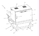
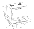
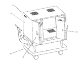
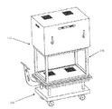
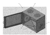
さて図4を参照すると、新規の滅菌キャビネット105と新規の移動カート200とを備えた新規の携帯用滅菌システム100が示されている。
These and other objects and features of the invention will be more fully disclosed or indicated by the following detailed description of the preferred embodiments of the invention and the preferred embodiments thereof. Should be considered in conjunction with the accompanying drawings, wherein like reference numerals designate like elements.
Referring now to FIG. 4, a new
滅菌キャビネット105は、通常、キャビネット底部125、キャビネット側壁126、キャビネット背面壁127、及びキャビネット上部140に包囲された矩形内部チャンバ110(図13)を備える。キャビネット105は、さらに、キャビネット105の内部チャンバ110を選択的に開閉する1つ以上のドア130を備えてもよい。キャビネット105は、さらに、ドアの閉鎖時、キャビネット105を封止するため、キャビネット105のドアとフレームとの境界にガスケット(図示せず)を備えてもよい。
キャビネット105の内部チャンバ110は、チャンバ110内で手術用トレイ、器具等を支持する棚145(図23)も備えることが好ましい。
The
The
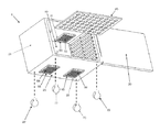
さらに、キャビネット105は、キャビネット側壁126、キャビネット背面壁127、キャビネット上部140、及びキャビネット底部125の少なくとも1つに形成された1つ以上の通気口135を備える。通帰口135は、フィルタ150に被覆され、フィルタカバー155(図23)は、通気口135上の所定位置にフィルタ150を保持する。滅菌キャビネット105のさらなる詳細(例えば、ドア130、フィルタ150、棚145等の改良)をいかに詳述する。
In addition, the
表面に沿って(例えば、床、移動カート200等に沿って)滅菌キャビネット105を移動するため、滅菌キャビネット105は、複数のキャスタ又はホイール160を備える(通常、模式図中に示すもの)。本発明の好適な一様態において、キャスタ又はホイール160は、例えば、従来既知のホイールブラケット又はキャスタブラケット(後述)を介して、キャビネット底部125に搭載される。キャスタ又はホイール160は、図面の角度により、多数の図面中に示されていないものの、図7(C)、13、22(A)、22(B)、23、24、25(A)、27、29(D)、30(D)、36、37、39、41、43、及び44中に明確に見出すことができることに留意する。
To move the
滅菌キャビネット105は、そのキャスタ又はホイール160を介して床に沿って移動させられるが、多くの状況において、滅菌キャビネット105を移動カート200に乗せて、例えばオートクレーブ、手術室、又は保管室に移動することが望ましい可能性がある。
The
より具体的には、移動カート200は、場所間の搬送のために滅菌キャビネット105に配置されてもよいプラットフォームを提供する。例示であり限定を意図するものでないが、移動カート200は、滅菌キャビネット105を設備の一部から他の一部(例えば、滅菌処理部又はオートクレーブから手術室へ)移動するために使用されてもよい。また例示であり限定を意図するものでないが、移動カート200は、滅菌キャビネット105を保管庫から出し入れし、且つ/又は、滅菌キャビネット105をオートクレーブから出し入れし、且つ/又は、滅菌キャビネット105を設備間又は病室間で移動させるために使用されてもよい。
More specifically,
移動カート200は、通常、滅菌キャビネット105を受容する上方プラットフォーム205(図4)と、移動カートを場所間で移動させる機構(例えば、ホイール)の搭載される下方プラットフォーム210とを備える。上下昇降機215は、上方プラットフォーム205と下方プラットフォーム210との間に延びる。移動カート200は、移動カート200を場所間で操作するハンドル220を備えることが好ましい。
The
さて図4及び図5を参照すると、移動カート200は、移動カート200を場所間で移動させる旋回キャスタ225を備える。キャスタ225は、キャスタ225に設けられた、アクセスの容易な足踏式ペダル調整、又はハンドル220で実施される調整により、旋回状況と非旋回状況とに調整されてもよい。換言すると、ユーザは、キャスタが旋回可能な第1構成及びキャスタ225の旋回がロックされた第2構成からキャスタ225を調整することができる。この特徴により、ユーザは、移動カート200を場所間で移動させる際、移動カート200にさらなる制御を行うことができるようになる。キャスタ225には、追加の安全特徴として、帯電防止を施すことができる。
4 and 5, the moving
移動カート200は、地形変化及び傾斜を超えて、また(医療器具又はその他の内容物が搭載された)器具トレイが滅菌キャビネット105内に配置された状態及び配置されていない状態で移送する間により平滑な「走行」を可能にする対応衝撃吸収懸架システムを備えてもよい。
The
例示であり限定を意図するものでないが、携帯用滅菌システム100は、遠隔地の滅菌処理会社により、遠隔地の滅菌処理設備から数百マイル離れていることもある医療設備又はその他の設備との間で搬送され、完全に搭載されてもよい。衝撃吸収懸架システムにより、搭載される医療器具の安全及び安心を向上し、搬送中に発生し得る損傷及び/又は変位を限定することができるようになる。
By way of example and not intended to be limiting,
図5に示すとおり、衝撃吸収懸架システムは、上下昇降機215の定位置において上方プラットフォーム205と下方プラットフォーム210との間に搭載されたキャスタ225及び/又は弾性ばね235に配置された衝撃吸収懸架ばね230を備えてもよい。
As shown in FIG. 5, the shock absorbing suspension system includes a shock absorbing suspension spring 230 disposed on a caster 225 and / or an elastic spring 235 mounted between the
或いは、上下昇降機215は、伸縮構成に形成されてもよく、弾性ばね235が伸縮上下昇降機215の周囲及び/又は内側に配されてもよい。弾性ばね235は、キャスタ225が移動カート200に衝撃を生じる凹凸又はその他の表面異常に直面してした際、上方プラットフォーム205(及び滅菌キャビネット105)に衝撃吸収機能を付与するように、上方プラットフォーム205及び下方プラットフォーム210を互いから離間して付勢するように設定される。携帯異滅菌システム100の搬送中の衝撃吸収を付与するように、追加衝撃吸収ばね230又は弾性ばね235が移動カート200の他のいずれかの耐荷重部に搭載されてもよい。
Alternatively, the
移動カート200はまた、「デッドマン」安全グリップ及び/又は自動ブレーキシステムも備えてよい。より具体的には、また図5を参照すると、デッドマン安全グリップ240が示されている。デッドマン安全グリップ240は、キャスタ(又はその他のホイール)の移動を防ぐ(図示せず)ことのできる1つ以上のホイールブレーキに対して(電気的、機械的、又はその他の方法で)接続される。本発明の一様態において、ホイールブレーキは、デフォルト位置で移動カート200のキャスタ225にブレーキが掛けられることにより、移動カート200の移動を阻止するように構成される。デッドマン安全グリップ240がユーザによって駆動されると、ホイールブレーキは第2構成に移動することにより、ホイールを自由回転させる。従って、ホイール(引いては移動カート)は、デッドマン安全グリップ240が駆動されるまで、回転しないようにされる。この特徴により、滅菌キャビネット105を移動カート200に対して積み降ろしする間、及び滅菌キャビネット105の内容物を積み降ろしする間、フールプルーフブレーキを提供するものである。
The
移動カート200はまた、移動カート200に組み込まれるか、取り付けることのできる動力アシスト機構245(図4)も備えてよい。図5に示すとおり、動力アシスト機構245は、モータ/サーボ動力アシストハンドル又はその他の制御(図示せず)がユーザによって(例えば、バイクのスロットルグリップのようにハンドルを回転させることにより)駆動されると、キャスタ225を駆動するモータを備えてもよい。動力アシスト機構245は、より長距離のより重量の重い加重を搬送する際、傾斜、及び/又は、凹凸面で搬送を行う際にアシストしてもよい。動力アシスト機構245は、前方又は逆にホイールを駆動してもよい。
The
さて図6を参照すると、一実施形態において、移動カート200には、移動カートが場所間の搬送の際に他の移動カートを引っ張る(又は押す)のに使用されてもよいように、移動カートを1つ以上の他の移動カート200に連結する機構が設けられてもよい。このような連結能力を有効にするため、移動カート200は、移動カート200の下方プラットフォーム210の一端に設けられた雄型部品250と、移動カート200の下方プラットフォーム210の反対側端部に配された雌型部品255とを備えることにより、所定のカートの雄型部品又は雌型部品が他のカートの相補雄型部品又は雌型部品に連結されるようにしてもよい。雄型部品250及び雌型部品255の一方又は双方は、移動カート又は牽引/連結特徴が使用中でない時、移動カート200の下方に退避させるか、又は折り畳んで置くことができる。
Referring now to FIG. 6, in one embodiment, the
一実施形態において、移動カート200は、移動カート200及びその他の対象を保護し、移動カート200の一箇所から他の箇所への移動(例えば、病院の廊下を通って搬送する間)を促進する緩衝器及び/又はローラ260(図7(A))を備えて構成されてもよい。
In one embodiment, the
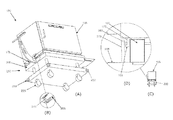
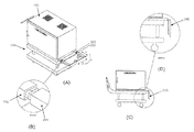
さて図7(A)〜図7(D)を参照すると、移動カート200は、相補的に構成された進路又はレールと係止ラッチ又は同様の装置の組み合わせにより、キャビネット105に対して解放可能に固定されることが好ましい。
Referring now to FIGS. 7A-7D, the
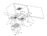
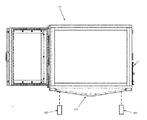
移動カート200は、(キャスタ又はホイール160をキャビネット105に搭載する)相互係止キャスタブラケットを捕らえるため、相互係止進路又はレールの改良安全特徴を備えることが好ましい。より具体的には、リップ265は、それ自体が移動カート200の上方プラットフォーム205の側面又は上面から上方に延びる一対の移動カート進路又はレール270から胴体内に延びる(すなわち、進路又はレール270は、移動カート200の各側方に沿って延びる)。リップ265は、キャビネット105を移動カート200上に配置しつつ、移動カート200に対して滅菌キャビネット105が横方向(すなわち左右方向)又は上下方向に移動してしまうことを防ぐよう、キャビネットのキャスタブラケット又はホイールブラケット170の長尺突起165に対して摺動可能に係合する。
The
移動カート200及び滅菌キャビネット105は、キャビネット105を移動カート200に固定して維持する自動係止特徴を提供するよう形成されることが好ましい。より具体的には、図7(A)及び図7(B)を参照すると、移動カート200は、移動カート200の上方プラットフォーム205に搭載される中央係止ラッチ275を備えて構成されてもよい。中央係止ラッチ275は、バー175がラッチ275に受容された後、滅菌キャビネット105が移動カート200に対して前方又は後方から移動することを阻止するよう、滅菌キャビネット105の底部を横切って延びるバー175を受容してもよい。
The
移動カート200は、異なる滅菌キャビネット又はその他の積み荷の寸法、及び/又は、滅菌キャビネット105の異なる目的地の寸法(例えば、異なるオートクレーブ又は保管ラック)を収めることができるように、調整可能なレール設置及び取付を提供することにより「ユニバーサル」に構成されることが好ましい。
The
より具体的には、図8(A)〜図8(D)を参照すると、移動カート200は、図8(A)に示す方向性矢印1又は3に沿って調整可能な幅を有するユニバーサルレール設置280と、同様に調整可能な幅を有する脱着式アダプタ285とを備えて構成されてもよい。調整可能なレール280及びアダプタ285は、図8(B)に示す雄/雌構成のように、滅菌キャビネット105を移動カート200から目的地(例えば、保管ラック、オートクレーブ等)に移動する平滑な面を与えるよう、互いに嵌合されてもよい。ユニバーサルレール210及びアダプタ285の幅は、少なくとも部分的に、目的地の対応特徴の幅を参照して決定される(例えば、保管ラック又はオートクレーブの関連要素の幅によって決定されてもよい)。
More specifically, referring to FIG. 8 (A) to FIG. 8 (D), the
アダプタ285は、(図8(A)に示すような)上方プラットフォーム205の上方にまっすぐ延びるか、又は、移動カート200の端部にて突出しないように(図8(C)及び図8(D)に示すように)折り畳まれるよう構成されてもよい。或いは、アダプタ285は、移動カートから全体的に取り外しできるように構成されてもよい。アダプタ285は、さらに、移動カート200から取り外し可能に構成される場合、移動カート200上の目立たない箇所に収容されてもよく、又は、使用に備えて目的地付近に保管されてもよい。
The adapter 285 extends straight above the upper platform 205 (as shown in FIG. 8A) or does not protrude at the end of the mobile cart 200 (FIGS. 8C and 8D). It may be configured to be folded (as shown). Alternatively, the adapter 285 may be configured to be totally removable from the mobile cart. The adapter 285 may further be housed in an inconspicuous location on the
上述の嵌合特徴により、生産性を向上し、コストを削減し、携帯用滅菌システム100の(例えば、病院通路の)移動の容易さ及び安全を向上する。アダプタ285が(図8(C)及び図8(D)に示すとおり)取り外され、且つ/又は、折り畳まれると、携帯用滅菌システム100の前方端部に、鼻先の丸く、より短く、より危険性の低いカート前方部が現れる。上述のとおり、アダプタ215は、折り畳み又は収容可能要素として各移動カート200とともに留まるか、所望の目的地(例えば、オートクレーブに隣接した保管対象の滅菌処理部、若しくは保管ラック又はラックシステムの隣)に置かれたままとされてもよい。
The mating features described above improve productivity, reduce costs, and improve the ease and safety of movement of portable sterilization system 100 (eg, in a hospital aisle). When adapter 285 is removed and / or folded (as shown in FIGS. 8C and 8D), the nose tip is rounded, shorter and more dangerous at the front end of
本発明の他の実施形態において、ユーザのニーズに応えるため、移動カートの上方プラットフォーム(及び、引いては上方プラットフォームに固定された滅菌キャビネット105)を昇降するように上下に調整可能な代替の移動カートが提供される。一例として、移動カートの上方プラットフォームは、場所間の搬送の間、より視認されやすいように降下され、滅菌キャビネットを所望の場所で開放するとき、所望の高さまで上昇されるものとすることができる。
In another embodiment of the present invention, an alternative movement that can be adjusted up and down to raise and lower the upper platform of the mobile cart (and thus the
上下に調整可能な移動カートは、(例えば、以下にさらに詳述するとおり、シザーリフト等で)機械的に昇降されてもよく、バッテリー動作動力装置又はその他の適切な手段により、電子方式、油圧式、空気圧式に昇降されてもよい。
図9を参照すると、このような目的で、上下に調整可能な移動カート300が提供される。
A movable cart that can be adjusted up and down may be lifted mechanically (eg, with a scissor lift, etc., as will be described in more detail below), electronically, hydraulically by battery operated power equipment or other suitable means. May be raised or lowered in a pneumatic or pneumatic manner.
Referring to FIG. 9, a
上下に調整可能な移動カート300は、上下昇降機215及び下方プラットフォーム210が上端320及び下端325を有するシザーリフト315に置き換えられることを除いて、上述の移動カート200と略同様である。
The
滅菌キャビネット105は、上述と同様に、移動カート300の上方プラットフォーム305に固定される。シザーリフト315は、場所間で移動するため、その上端320にて上方プラットフォーム305に接続され、その下端325にてホイール330に接続される。
本発明のこの様態によると、シザーリフト315は、上方プラットフォーム305を床と略同一面となるまで降下させるよう駆動されてもよい。
The
According to this aspect of the invention, the scissor lift 315 may be driven to lower the upper platform 305 until it is substantially flush with the floor.
図10を参照すると、本発明の他の実施形態において、上下に調整可能な移動カート400が提供される。移動カート400は、上下昇降機215が上端420及び下端425を有するシザーリフト415に置き換えられることを除いて、上述の移動カート200と略同様である。
Referring to FIG. 10, in another embodiment of the present invention, a movable cart 400 that is adjustable up and down is provided. The mobile cart 400 is substantially similar to the
より具体的には、移動カート400は、上述のとおり、滅菌キャビネット105に固定される上方プラットフォーム405と、下方プラットフォーム410と、上方プラットフォーム405及び下方プラットフォーム410の間に延びるシザーリフト415とを備える。
More specifically, the mobile cart 400 includes an upper platform 405 fixed to the
上述のとおり、本実施形態のシザーリフト415の駆動により、上方プラットフォーム405を上下に移動させるが、上方プラットフォーム405は、地面の高さまで完全に下降されることはない(すなわち、下方プラットフォーム410のレベルまで下降される)。本実施形態により、移動カート400にさらなる安定性を付与することができる。 As described above, the upper platform 405 is moved up and down by driving the scissor lift 415 of the present embodiment, but the upper platform 405 is not completely lowered to the level of the ground (that is, the level of the lower platform 410). Down). According to the present embodiment, further stability can be imparted to the moving cart 400.
移動カート300及び400のシザーリフト315及び415は、各々、機械的手動、油圧式、又は空気圧式のハンドポンプであり得る、若しくは電気又はバッテリーの動作により、動力補助(機械的、油圧式、空気圧式等)されてもよい昇降機構によって駆動(すなわち昇降)されてもよい。
The scissor lifts 315 and 415 of the
また移動カート300及び400は、ユーザが電子制御システムに特定の高さを事前プログラムできるようにしてもよく、所望の高さ(例えば、滅菌キャビネットを特定のオートクレーブ内に投入するための高さ、若しくは手術室又は滅菌処理部にて滅菌キャビネットの積み降ろし又は搬送を行うスタッフに合わせた好適な高さ)を想定するよう移動カートに支持を行う(図11に示し、以下により詳述するような)電子制御システムを備えてもよい。この特徴により、高さ調整が可能となることで、看護師又は技術者の身長により、滅菌フィールドを侵害してしまうことなく、人間工学的効果を付与する。
The
上述の高さ調整の追加の効果として、滅菌キャビネットは、搬送中、キャビネットの上部の上方の視野を改善するよう下降させることができ、且つ、転倒の可能性を低減するよう、重心を下げることができる。上述のとおり、ユーザにより、事前プログラムされた高さを設定してもよい。 As an additional effect of the height adjustment described above, the sterilization cabinet can be lowered during transport to improve the field of view above the top of the cabinet and lower the center of gravity to reduce the possibility of tipping. Can do. As described above, a preprogrammed height may be set by the user.
さて図11を参照すると、本発明の移動カート(例えば、移動カート200、300、及び400)は、移動カート及び滅菌キャビネット105の内容物をトラッキング及び/又は識別する電子制御システム290も備えてよい。
Referring now to FIG. 11, the mobile carts (eg,
より具体的には、本発明の移動カートの電子制御システム290は、LOJACK(登録商標)等の装置又は類似の追跡システムにより、電子的に追跡される能力を有することが好ましい。換言すると、移動カートの位置(例えば、建物、床、部屋)は、グローバルポジショニングシステム(GPS)、無線自動識別(RFID)、又はその他の位置トラッキング装置を使用して遠隔モニターされてもよい。 More specifically, the mobile cart electronic control system 290 of the present invention preferably has the ability to be electronically tracked by a device such as LOJACK® or a similar tracking system. In other words, the location of the mobile cart (eg, building, floor, room) may be remotely monitored using a global positioning system (GPS), wireless automatic identification (RFID), or other location tracking device.
また電子制御システム290は、特定の滅菌キャビネット105、滅菌キャビネット105の内容物(例えば、トレイ又は器具)、その位置、現在の温度、及び/又は滅菌状態(例えば、滅菌前、滅菌後、滅菌状態、又は非滅菌状態等)を特定するため、RFID又はその他の識別技術を使用してもよい。電子制御システム290は、特に、日付、オペレータ、サイクル、サイクルタイプ、及び滅菌キャビネット105の内容物等の追加情報も提供してよい。
電子制御システム290によって提供された情報は、スクリーン上でユーザに表示されるか、スピーカーを通じてユーザーに音声伝達されてもよい。
The electronic control system 290 may also include a
Information provided by the electronic control system 290 may be displayed to the user on a screen or may be voiced to the user through a speaker.
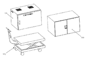
さて図12を参照すると、ユニバーサル移動カート500が提供される。ユニバーサル移動カート500は、滅菌キャビネット105用の移動カートとしてのみならず他の装置(例えば、器具トレイを滅菌しないものの保持する相互交換可能なケースカート要素505)用の移動カートとして動作してもよい。滅菌キャビネット及びケースカート要素は、保管ラックシステム上で、例えば、4つのキャビネットの高さまで上下に積み上げることができる。例えば、図20を参照すると、互いに上下に積み上げられた2つの滅菌キャビネット105を(模式的に)示している。
さて図13〜27を参照して、滅菌キャビネット105の追加特徴をさらに詳細に述べる。
Referring now to FIG. 12, a universal mobile cart 500 is provided. Universal mobile cart 500 may operate not only as a mobile cart for
Additional features of the
本発明の好適な様態において、ドア130は、滅菌キャビネットチャンバ105の内部へのアクセスが求められる時に必要とされる設置面積を最小化するため、種々の構成で提供することができる。
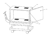
さて図13を参照すると、本発明の一実施形態において、ドア130は、滅菌キャビネット105の一方側にヒンジ留めされ、180°開放することができる。
In a preferred aspect of the present invention, the
Referring now to FIG. 13, in one embodiment of the present invention, the
さて図14を参照すると、本発明の他の実施形態において、ドア130は、ドア130が270°開放されるように、ヒンジ180でキャビネットの側壁126に搭載することができる。ドア130及び側壁126は、所望に応じて、キャビネット105の側壁126に近接して(且つ、凡そ平行に)開放したドアを保つことにより、ドア130の開放時のキャビネット105の全体設置面積を低減するため、ドア130を解放可能にキャビネット105の側壁126に固定するような装置(例えば、Velcro(登録商標)ファスナー等の「フック及びメッシュ」ファスナー)を備えてもよい。
Referring now to FIG. 14, in another embodiment of the present invention, the
さて図15を参照すると、本発明の他の実施形態において、ドア130は、各ドア130(図示せず)の中間及び周囲においてガスケット又はその他の封止部により、一対のフレンチドア130を備えることができ、双方のフレンチドア130が任意で開放され、上述のとおり、キャビネットの側方に解放可能に取り付けられる。
Referring now to FIG. 15, in another embodiment of the present invention, the
さて図16及び17を参照すると、本発明のさらに他の実施形態において、ドア130は、滅菌キャビネット105の左側及び右側壁部126に沿って配置された内側又は外側トラック(図示せず)に沿って、(図16に示すとおり)下方向又は(図17に示すとおり)上方向に開放及び摺動することができる。或いは、ドア130は、滅菌キャビネット105(図示せず)の上部の上方を揺動されてもよい。
Referring now to FIGS. 16 and 17, in yet another embodiment of the present invention, the
さて図18を参照すると、本発明のさらに他の実施形態において、ドア130は、内部チャンバ110を露出するように開放(及び折り畳み)されてもよい1つ以上の2つ折りドア130からなってもよい。本発明の好適な一様態において、2つ折りドア130は、ドア130が滅菌キャビネット105の側壁126にほぼ平行に配置されてもよいように、(例えば、上述のとおり)270°折り畳まれてもよい。さらに2つ折りドア130及び側壁126は、ドア130が双璧126に対して後方に折り曲げられるとき、(例えば、Velcro(登録商標)ファスナー等の「フック及びメッシュ」ファスナーで)側壁126に対してドア130が解放可能に固定されるように構築されることが好ましい。
Referring now to FIG. 18, in yet another embodiment of the present invention, the
本発明の他の一様態において、滅菌キャビネットは、ドアでなく、ドーム型閉鎖上部(図示せず)を有することができる。すなわち、滅菌可能なキャビネットの上部は、滅菌キャビネットの内容物を露出するよう、上方に移動することができる。ドーム型上部の形状は、通常、滅菌キャビネットの周囲を気密にするよう構成される。 In another aspect of the invention, the sterilization cabinet can have a dome-shaped closure top (not shown) rather than a door. That is, the upper part of the sterilizable cabinet can be moved upward to expose the contents of the sterilization cabinet. The shape of the dome-shaped upper part is usually configured to be airtight around the sterilization cabinet.
従ってドーム型上部は、滅菌キャビネット110のフレーム上部にぴったり合ういずれの形状であってもよい。本実施形態において、ドーム型上部は、滅菌キャビネット105の内容物を露出するよう(例えば、手動、機械的、電子的アシスト等によって)上昇させることができる。所望に応じて、滅菌キャビネット105の内容物を完全に見ることができるように、ドーム型上部を透明素材で形成してもよい。
Accordingly, the dome-shaped upper portion may have any shape that fits the frame upper portion of the
さて図19を参照すると、本発明のさらに他の一様態において、滅菌キャビネット110は、フレームを備えてもよく、背面壁127、側壁126、及びドア130がフレーム185から緩められ、移動カート200の外側の内側進路又は外側進路に沿って滑り降りることができる。本発明の本実施形態において、移動カート200のハンドル220は、進路に沿った側壁及び/又はドアの平滑な摺動を促進するよう、取り外し可能であってもよい。
Referring now to FIG. 19, in yet another aspect of the present invention, the
本発明の他の好適な一様態において、ユーザが、滅菌キャビネットのドアを開放する必要なく、滅菌キャビネットの内容物にアクセスできるようにする手段が提供されてもよい。 In another preferred aspect of the invention, means may be provided to allow a user to access the contents of the sterilization cabinet without having to open the sterilization cabinet door.
より具体的には、滅菌キャビネットの内容物が見えるように、滅菌キャビネット105全体が、透明素材(例えば、ガラス、透明ポリマー等)から形成されてもよい。例えば図20を参照すると、移動カート200の上部に配置された透明滅菌容器105と、透明滅菌容器105の上部に配置された第2の非透明滅菌容器105とを示している。
More specifically, the
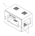
さて図21を参照すると、他の実施形態において、滅菌キャビネット105は、滅菌キャビネット105の側壁126、背面壁127、又はドア130の1つ以上に配置された1つ以上の窓190(又は(「オーブンドア」)を備えてもよい。これにより、キャビネットの内容物と、所望の装備及び器具のすべてが入っているか否かを査定するように、キャビネット内を見えるようにする。
Referring now to FIG. 21, in another embodiment, the
キャビネット全体又は窓190は、所望により、高温ポリカーボネート材料、及び/又は、透明から半透明に変化する「切替型」スマートグラス/フィルム、及び/又は、(例えば、「滅菌」又は「非滅菌」を示す)その他の好適な材料で形成されてもよい。 The entire cabinet or window 190 may be made of high temperature polycarbonate material and / or “switchable” smart glasses / films that change from transparent to translucent, and / or (eg, “sterile” or “non-sterile”, as desired. It may be formed of other suitable materials (shown).
本発明の他の一様態において、フィルタの交換又はアクセスのため、フィルタへのアクセスを改良するため、改良フィルタ及びフィルタポートが提供される。さて図22(A)及び図22(B)を参照すると、滅菌キャビネット105は、キャビネットの外側からアクセス可能なフィルタポート152を備えることにより、フィルタ150の確認及び変更のためのアクセスをより容易にしてもよい(例えば、フィルタカバー155に比して容易にしてもよい)。例示であり限定を意図するものでないが、外部からアクセス可能なフィルタポート152は、フィルタ150を摺動可能に受容し、通気口135上にフィルタを配置するための引き出し型アクセス棚を備えてもよい。フィルタ150は、フィルタポート152において通気口135上の所望の位置に摺動可能に配置された後、(フィルタ150を所定位置において解放可能に係止する)カム機構156を制御する係止バー154によって所定位置に保持されてもよい。
In another aspect of the invention, improved filters and filter ports are provided to improve access to the filter for filter replacement or access. Referring now to FIGS. 22A and 22B, the
フィルタ150は、ボール紙、フィルタカセット、再利用可能カーボンフィルタ、又はその他のフィルタ素材と、従来既知の構造を備えてもよい。フィルタ150はまた、フィルタ材料の2層をともに縫い付け、糊付け、ケース封入、圧接、又は押圧し、所望のサイズに形成することによって生成された2層フィルタであってもよい。
The
フィルタ150はまた、そのステータスに関する情報を伝えるよう色を変化させてもよい(例えば、第1カラーは、フィルタが使用に好適であることを示し、第2カラーは、フィルタを使用せず、交換すべきであることを示してもよい)。
The
従って、本発明の好適な一様態において、フィルタは、滅菌キャビネットの滅菌後(滅菌プロセスが所定のパラメータを満たす限り)、フィルタ内又はフィルタ上に(顧客によるリクエストを含む、所望のパターンで)薬剤を添加するプロセスを使用して製造される。換言すると、フィルタ自体は、滅菌プロセス中に使用されてもよい他のすべてのインジケータに加え、クラス5のステータスインジケータとなる。この種のフィルタは、一度使用して使い捨てるフィルタが確実に一度のみ使用されるように、フェイルセーフ機構を提供するため、現在市場で入手可能なフィルタを超える多大な改良である。これにより、手術室のスタッフは、プロセスが達成されたことを大型のフィルタ材料を一目見て視覚的に確認することができるようにもなる。
フィルタ150はまた、既存の滅菌キャビネット及び/又は携帯用滅菌システム100との連携する以外の目的のために使用されてもよい。
本発明のいくつかの適用例において、キャビネットとともにいずれのフィルタも使用しないことが適切であってもよい。
Thus, in a preferred embodiment of the present invention, the filter can be used after the sterilization of the sterilization cabinet (as long as the sterilization process meets certain parameters), in the filter or on the filter (in the desired pattern, including customer requests) Manufactured using a process of adding. In other words, the filter itself becomes a
In some applications of the present invention, it may be appropriate not to use any filter with the cabinet.
図13を再び参照すると、滅菌キャビネット105は、滅菌プロセス中、キャビネット内に蓄積した水を取り除くため、キャビネット床部125に配置された排出口195を有してもよい。本構造において、排出口195は、滅菌キャビネット110の底部の最低点に配置される。底部パネル125は、パネルの中途であるか、パネルの一方側に沿っているか、又はパネルの隅であるかを問わず、パネルの最低点までピッチを備えて設計されることが好ましい。各キャビネットには、1つ以上の排出口が使用されてもよい。
Referring again to FIG. 13, the
排出口195は、所望に応じて、温度制御されてもよい。本発明の本様態において、排出口195は、例えば、温度変化に応じて構成を変化し得る日ノール等の形状記憶合金等、いわゆる「バイメタル」構造を備えて形成されてもよい。例示であり限定を意図するものでないが、排出口195は、滅菌プロセス中に生成される過剰な水を解放するために、滅菌キャビネット内の温度がより高い時には開放され、滅菌キャビネットを潜在的汚染物から封止するように、滅菌キャビネット内の温度がより低い時に閉鎖する。 The outlet 195 may be temperature controlled as desired. In this aspect of the present invention, the outlet 195 may be formed with a so-called “bimetal” structure, such as a shape memory alloy such as Ninol that can change its configuration in response to temperature changes. Although illustrative and not intended to be limiting, the outlet 195 is opened when the temperature in the sterilization cabinet is higher to release excess water generated during the sterilization process, potentially contaminating the sterilization cabinet. Closed when the temperature in the sterilization cabinet is lower so as to seal from the object.
他の実施形態において、排出口195は、滅菌キャビネット内の圧力レベルに応じて、開閉してもよい。例示であり限定を意図するものでないが、排出口195は、滅菌プロセス中に生成される過剰な水を解放するため、滅菌キャビネット内の圧力が特定レベル内のとき開放され、滅菌キャビネット内の圧力が特定レベル内のとき、滅菌キャビネットを潜在的汚染物から封止するように閉鎖するよう構成されてもよい。 In other embodiments, the outlet 195 may open and close depending on the pressure level in the sterilization cabinet. By way of example and not intended to be limiting, the outlet 195 is opened when the pressure in the sterilization cabinet is within a specified level to release excess water generated during the sterilization process, and the pressure in the sterilization cabinet. May be configured to close to seal the sterilization cabinet from potential contaminants.
さらに他の実施形態において、排出口195は、滅菌プロセス以降経過した時間に応じて開閉するよう構成されてもよい。例示であり限定を意図するものでないが、排出口195は、滅菌処理中に生成される過剰な水を解放するため、滅菌キャビネットの内容物を滅菌する時間中、開放され、滅菌キャビネットを潜在的汚染物から封止するよう、滅菌キャビネットの内容物を滅菌した後、閉鎖されるよう構成されてもよい。 In yet another embodiment, the outlet 195 may be configured to open and close depending on the time elapsed since the sterilization process. Although illustrative and not intended to be limiting, the outlet 195 is open during the time to sterilize the contents of the sterilization cabinet to release excess water generated during the sterilization process, potentially It may be configured to be closed after sterilizing the contents of the sterilization cabinet to seal from contaminants.
本発明のさらに他の実施形態において、滅菌キャビネット110は、従来の滅菌キャビネットに比して、内部の棚設置の面倒を緩和するよう改良された棚管理オプションを備える。
In yet another embodiment of the present invention, the
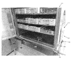
さて図23を参照すると、より具体的には、滅菌キャビネット105は、キャビネット内でクリップを調整する必要なく、多数の高さで棚145を容易に取り外し、交換するため、リンクルウォール又はスタンプウォール146を備えて構成されてもよい。本発明のこの様態において、棚145は、種々の高さに調整可能であり、この調整は片手で(例えば、棚を「絞って解放する」か、その他類似の代替動作により)達成されることが好ましくてもよい。
或いは、図24を参照すると、設置棚支持部147が、棚145を支持するようにキャビネット110にボルト留めされてもよい。
Referring now to FIG. 23, more specifically, the
Alternatively, referring to FIG. 24, the
さて図25(A)及び図25(B)を参照すると、本発明のさらに他の一様態において、棚145は、ばね負荷ペグ148によって設置棚支持部147に取り付けられてもよい。
Referring now to FIGS. 25A and 25B, in yet another aspect of the present invention, the shelf 145 may be attached to the
他の実施形態において、引き出しスタイルの棚も使用されてよい(図示せず)。さらに、棚は、滅菌プロセスを補助し、且つ/又は、その他の効果をもたらしてもよい種々の材料で構築されてもよい(例えば、棚は、熱伝達性により優れたアルミニウムによって形成されてもよく、又はより安価な材料等によって形成されてもよい)。
他の実施形態において、本発明は、滅菌キャビネットの内部においてより小さな領域を分離する能力を有する滅菌キャビネットを提供する。
より具体的には、図26を参照すると、滅菌キャビネット105は、キャビネット105内に多数のチャンバ110を提供するよう構成されてもよい。
In other embodiments, drawer style shelves may also be used (not shown). In addition, the shelves may be constructed of a variety of materials that may aid in the sterilization process and / or provide other benefits (eg, shelves may be formed of aluminum with better heat transfer properties). Or may be made of a cheaper material or the like).
In another embodiment, the present invention provides a sterilization cabinet that has the ability to separate smaller areas within the sterilization cabinet.
More specifically, referring to FIG. 26, the
より具体的には、本発明のこの様態において、滅菌キャビネット105は、分離された個別のチャンバ110を備え、これらは各々、別のドア130によってアクセス可能である。各チャンバ110は、滅菌プロセス中、上記又は熱の通過を可能にする自身の通気口135及びフィルタ150を備えることが好ましい。また各個別チャンバ110は、区画の滅菌/非滅菌状態を示す(以下にさらに詳述するものと同一又は同様の種別の)滅菌/非滅菌インジケータ197を有してもよい。
More specifically, in this aspect of the invention, the
区画分けにより、いくつかのチャンバ110の内容物を異なる処置に使用するというオプションを提供する。換言すると、すべてのチャンバ110及びその内容物は、同時に滅菌することができ、個別チャンバ110の内容物は、その他のチャンバ110又はそれらの内容物の滅菌状態を損なうことなく、使用することができる。例示であり限定を意図するものでないが、4つのトレイ(1つ以上のチャンバ110に配置)を「4つのトレイの処置」(すなわち、4つのトレイの滅菌済み医療器具を必要とする医療処置)のために手術室に運ぶことができ、同一の滅菌キャビネット105内の別セットのチャンバ内に配置された他の8つのトレイを「8つのトレイの処置」(すなわち、8つのトレイの滅菌済み医療器具を必要とする医療処置)のために第2の手術室に運ぶことができる。区画分けされた滅菌キャビネット105は、移動カート200との組み合わせで、1を超える医療処置のための運搬システムとして機能することができ、滅菌済みのトレイを運搬するのに要するスタッフが少なくて済み、且つ所望の場所にトレイを運搬するのに要する装備が少なくて済むということを含む、いくつかの効率向上を図るものであるが、これに限定されるものでない。
Partitioning provides the option of using the contents of
上述の内容に加え、滅菌キャビネット105は、滅菌処理の完了判定を補助するか、又はキャビネットのステータスについての追加情報(例えば、滅菌キャビネットが熱すぎて開放できないか否か等)を提供するため、追加の特徴を備えてもよい。
In addition to the above, the
例示であって限定を意図するものでないが、このような追加特徴には、キャビネットの窓又はパネルにおいて、キャビネットの滅菌処理後に色を変化させ、キャビネットの開放後(従って非滅菌状態とされる)に色を戻すインジケータが含まれてもよい。 By way of example and not intended to be limiting, such additional features include a color change in the cabinet window or panel after the cabinet has been sterilized and after the cabinet has been opened (and thus rendered non-sterile). An indicator for returning the color may be included.
さて図27を参照すると、キャビネット自体に配置された外部インジケータ197は、(例えば、「点灯」又は「冷」インジケータより「熱」インジケータをより視覚的に目立たせることにより)キャビネットが熱すぎて接触できない場合を示し、キャビネットが適切な取り扱い温度に達した時、「熱」インジケータを視覚的により目立たなくさせてもよい。同様に、他のインジケータ198は、(例えば、「点灯」するか、又は「滅菌」インジケータより「非滅菌」インジケータを視覚的により目立たせることにより)キャビネットのドアが開放されたか否かを示してもよい。このインジケータは、上述の方法により、ユーザに他の情報(例えば、ドアが「開放」されたか否か、又は「閉鎖」状態に維持されているか否か)を提供してもよい。
滅菌キャビネットのサイズ設定及び構成
Referring now to FIG. 27, the
Sizing and configuration of sterilization cabinet
滅菌キャビネット105は、4つのトレイ、8つのトレイ、9つのトレイ、又は12個のトレイ等を受容するような特定サイズの滅菌キャビネットを含むが、これに限定されない多数のサイズで製造可能である。
The
さらに図28を参照すると、各サイズのキャビネットが(例えば、オートクレーブの各サイクル用のオートクレーブチャンバにおいて)スペース使用を最大化するため、1つ以上の側壁126の外部に配置された別個の外部設置棚600を備えて製造することもできる。外部設置棚600は、包装済み器具の追加トレイ又は剛性容器を収容することができ、サイクル終了時に簡単に取り出すことができるよう、キャビネット105に対して取り付け可能である。外部設置棚600は、(外部設置棚600の場合のように)キャビネット105の外部に個別に搭載されてもよい。或いは、外部設置棚は、滅菌キャビネット105の側壁126に対して取り外し可能に取り付け(例えば、クリップ留め)することのできるラック650の形態を採ることもできる。各設置棚は、求められるサイズに応じてそれ自体の移動カートに備えられてもよく、すべての棚は、非使用時に簡単に保管できるように、コンパクト化又は折り畳みできてもよい。
構築材料
Still referring to FIG. 28, separate externally mounted shelves are located outside one or
Construction material
滅菌キャビネット105は、キャビネット作成の原料について多くのオプションを有する。本発明の好適な一様態において、滅菌キャビネット105は、ステンレス鋼から製造されてもよい。しかしながら、滅菌キャビネット105は、ステンレス鋼に加え、種々の材料から製造することもでき、(軽量版の製品や、陽極処理中の多数のカラーオプションの潜在性を可能にする)アルミニウム又はポリマーが含まれるが、これに限定されるものでない。
The
所望に応じて、ドアハンドル132、デッドマン安全グリップ240、及び携帯用滅菌システム100を移動させるために取り扱われる可能性のあるその他いずれかの表面は、滅菌処置に応じて、使い捨て衛生包装又はフィルムでカバーされてもよい。
代替構成
If desired, the door handle 132, deadman safety grip 240, and any other surface that may be handled to move the
Alternative configuration
滅菌キャビネット105は、医療処置中、「バックテーブル」として使用されるよう構成することもできる。より具体的には、(例えば、上述のドア構成及び/又は上述のドーム型上部等を介して)一旦滅菌キャビネットが開放されると、棚は、「ツールボックス」又は「タックルボックス」設計、揺動棚、又は可動棚システムを使用してユーザに示すことができ、これによって内側トレイのすべてに対するアクセスを容易にすることができる。
製造技術
The
Manufacturing technology
さて図29を参照すると、内側フレームの周囲に「ともにボルト留めされる」一実施形態に係る滅菌キャビネット105の展開図が示されている。より具体的には、滅菌キャビネット105は、フレーム112を備えてもよく、側壁126、背面壁127、上部壁140、及び底部壁125は、フレーム112に取り付けられてキャビネット105の内部チャンバ110を形成してもよい。各壁部は、ボルト113又はその他の好適な手段により、フレーム112に取り付けられてもよい。シーラント114又はOリング型シール(図示せず)は、気密封止を確保するよう、フレーム112の境界と、各壁部の間とに配置されてもよい。
Referring now to FIG. 29, there is shown an exploded view of a
さて図30を参照すると、本発明の他の実施形態において、滅菌キャビネット105の各壁部は、フレーム無しでともにボルト留めされてもよい。本実施形態において、側方パネル、背面パネル、上部パネル、及び底部パネルは各々、互いにボルト113で取り付けられ、シーラント114の層が各パネル間の境界に付与される。
Referring now to FIG. 30, in another embodiment of the present invention, the walls of the
図29及び図30に示す、本発明の実施形態は、組み立て前の滅菌キャビネットがより小さな輸送用容器で(例えば、上部パネル、底部パネル、側方パネル、背面パネル、及びドアを互いに平坦に横たえて)輸送可能であるため、輸送コストの削減を含むがこれに限定されない他の効果をもたらしてもよい。その後、滅菌キャビネットは、適切に訓練を受けた、従来既知の生物学的試験方法によって組み立ての適正さ(気密封止を含む)を査定できる者によって現場で組み立てることができる。
ドッキングステーション
The embodiment of the present invention shown in FIGS. 29 and 30 is a shipping container with a smaller sterilization cabinet prior to assembly (eg, top panel, bottom panel, side panel, back panel, and door lay flat against each other). And so on) may provide other benefits including, but not limited to, reduced transportation costs. The sterilization cabinet can then be assembled in the field by an appropriately trained person who can assess the suitability of the assembly (including hermetic sealing) by conventionally known biological testing methods.
Docking station
携帯用滅菌システム100は、任意のドッキングステーションとともに使用されるよう構成されてもよい。さて図30(E)を参照すると、ドッキングステーション700は、フレーム705と、ホイール715とを備える。フレーム705は、1つ以上の滅菌キャビネット105を受容するスペース720を提供する。ドッキングステーション700は、(追加の滅菌可能器具容器を受容可能である)棚725も備えることが好ましい。ドッキングステーション700は、それ自体が滅菌可能であり、オートクレーブ内に直接配置されてもよい。
本発明の好適な一様態において、移動カート200及びドッキングステーション700は、互いに解放可能に固定される。本発明のこの様態において、ユーザは、(滅菌キャビネット105を支持する)移動カート200をドッキングステーション700まで運んだ後、移動カート200をドッキングステーション700に対して解放可能に固定(又は、移動カート200からドッキングステーション700まで滅菌キャビネット105を移動する際に、移動カート200及びドッキングステーション700のいずれもが移動してしまわないように保証)してもよく、キャビネット105は、その後、移動カート200からドッキングステーション700上に容易に移動されてもよい。その後、移動カート200は、ドッキングステーション700から取り外され、ドッキングステーション700(及びそれに搭載された容器)が滅菌のためにオートクレーブ内に移動されてもよい。
In a preferred embodiment of the invention, the
携帯用滅菌システム100との連携でドッキングステーション700を使用するいくつかの効果には、(i)滅菌を必要とする追加容器も搭載されるドッキングステーション700上に滅菌キャビネット110が配置されてもよいため、オートクレーブのスペース利用効率を改善することと、(ii)滅菌キャビネット105が移動カート200からドッキングステーション700まで移動された後、他のユーザにより移動カード200を使用可能とすることが含まれるが、これに限定されるものでない。
Some advantages of using the docking station 700 in conjunction with the
この点、本発明のいくつかの様態において、(例えば、移動カート200によって電子部品等の感熱性且つ感湿性部品を搬送する場合)移動カート200は、滅菌可能であることを意図するものでないことに留意する。
改良型凝縮排出口及びフィルタポート
本発明のさらに他の一様態において、滅菌キャビネット105の性能を著しく向上するため、改良型凝縮排出口及びフィルタポートが提供される。
In this regard, in some aspects of the invention, the
Improved Condensate Drain and Filter Port In yet another aspect of the present invention, an improved condensate outlet and filter port are provided to significantly improve the performance of the
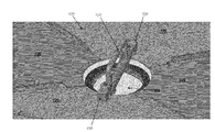
より具体的には、滅菌キャビネットから(蒸気としてではなく)液体として凝縮物を取り除くことにより、滅菌キャビネットの性能を著しく向上することが発見された。滅菌プロセス中に使用される蒸気は、滅菌プロセス中、相当量の凝縮物(すなわち、液体としての水)を生じることが分かっている。凝縮物は、重力により、滅菌キャビネットの最低点へと流れる。滅菌処理の乾燥フェーズ中、オートクレーブチャンバに真空が作用する。滅菌キャビネットの圧力がオートクレーブの圧力と等しくなると、凝縮物は、滅菌キャビネットの最低点に配された排出口(より具体的に後述)を通じて引っ張られ、滅菌キャビネットの外に出される。 More specifically, it has been discovered that removing condensate from the sterilization cabinet as a liquid (rather than as a vapor) significantly improves the performance of the sterilization cabinet. It has been found that the steam used during the sterilization process produces a significant amount of condensate (ie water as a liquid) during the sterilization process. The condensate flows by gravity to the lowest point of the sterilization cabinet. A vacuum is applied to the autoclave chamber during the drying phase of the sterilization process. When the pressure in the sterilization cabinet becomes equal to the pressure in the autoclave, the condensate is pulled through an outlet (more specifically described below) disposed at the lowest point of the sterilization cabinet and out of the sterilization cabinet.
より具体的には、図31〜図45を参照すると、本発明の好適な一実施形態において、無菌状態を侵害することなく、凝縮物を滅菌キャビネット105から逃す改良型排出口800が設けられる。排出口800は、滅菌キャビネット105の底壁部125の最低点に配される。滅菌キャビネット105は、凝縮物が重力によって底壁部125の最低点へと向かうようなピッチを有する床部を備えることが好ましい。
More specifically, with reference to FIGS. 31-45, in a preferred embodiment of the present invention, an improved outlet 800 is provided that allows condensate to escape from the
排出口800は、滅菌キャビネット105の底壁部125の最低点の下方に形成された凹部805を備える。このような排出口の構成により、キャビネット105内に湿気が残ることを防ぐ。凹部805は、熱を保ち、凹部805に流入した凝縮物の蒸発を向上するよう、厚いステンレス鋼又はその他の材料で形成されてもよい。
The discharge port 800 includes a recess 805 formed below the lowest point of the bottom wall portion 125 of the
排出口800は、凹部805の上方に配されたグリルプレート/スクリーン床部810を備えることが好ましい。グリルプレート/スクリーン床部810は、(より具体的に後述のとおり)フィルタを支持する剛性プラットフォームを提供する。グリルプレート/スクリーン床部810は、凝縮物が通過できるように透過性である。フィルタ815は、グリルプレート/スクリーン床部810の上部に配される。フィルタ815は、滅菌キャビネット105への汚染物の進入を防ぎつつ、凝縮物を通過させて滅菌キャビネット105から出すように構成する。
The outlet 800 preferably includes a grill plate / screen floor 810 disposed above the recess 805. The grill plate / screen floor 810 provides a rigid platform that supports the filter (as described more specifically below). The grill plate / screen floor 810 is permeable to allow condensate to pass through. The filter 815 is disposed on the top of the grill plate / screen floor 810. The filter 815 is configured to pass the condensate out of the
剛性フィルタドア820は、凹部805を横切ってフィルタ815の上部に配されることにより、フィルタドア820とグリルプレート/スクリーン床部810との間でフィルタ815を捕らえるようにする。フィルタドア820は、凝縮物を滅菌キャビネット105からフィルタドア820を通って通過させる穿孔部825を備える。フィルタドア820は、ハンドルブラケット835によって所定位置に保持されるハンドル830を備えて形成されてもよい。ハンドル830により、ユーザが、フィルタ815が要求に合わせて変更されるように、フィルタ815に対するアクセスを提供するように、フィルタドア820(後述)を容易に取り外せるようにする。フィルタ815は、ハンドル830をハンドルブラケット835の下方から回すことでフィルタドア820を取り外すことにより、変更されてもよい。
The rigid filter door 820 is disposed on top of the filter 815 across the recess 805 so as to capture the filter 815 between the filter door 820 and the grill plate / screen floor 810. Filter door 820 includes a perforation 825 that allows condensate to pass from
1つ以上のガスケット(図示せず)は、微生物汚染の通過を防ぐシールを形成するようなフィルタ815の1つ以上の側方に対して(例えば、フィルタドア820とフィルタ815との間、及び/又は、フィルタ815とグリルプレート/スクリーン床部810との間に)配置されてもよい。 One or more gaskets (not shown) may be placed against one or more sides of the filter 815 (eg, between the filter door 820 and the filter 815, and so on) to form a seal that prevents the passage of microbial contamination. (Or between the filter 815 and the grill plate / screen floor 810).
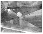
上述のことに加えて、蒸気の透過を改良し、通気質量比を改良するため、(その他の場所の代わりに、又はその他の場所に加えて)滅菌キャビネット105の側壁126に配される改良型フィルタポート900(図36)を備えて滅菌キャビネット105を構成することが有利であるとも分かっている。フィルタポート900は、滅菌キャビネット105のパネルに円形門として構成されてもよい。フィルタポート900は、単一の取付点910(例えば、円形の中心)及びフィルタガスケットの均一な圧縮(より具体的に後述)を可能にする円形プレート905でカバーされる。
In addition to the above, an improved version disposed on the
フィルタポート900は、フィルタ915と、穿孔部920を有するプレート905とを備え、フィルタ915及びプレート905は、滅菌キャビネット105の側方に形成される穿孔部と並んで、滅菌キャビネット105の外側に搭載されるか、又は滅菌キャビネット105の内側に搭載される。穿孔部920により、蒸気を滅菌キャビネット105に出し入れすることが可能となる。1つ以上のフィルタ915が円形プレート905とキャビネット105との中間に配置され、微生物汚染物の通過を防ぐ。
The
円形プレート905は、プレート905とフィルタ915との間に効果的なシールを作るようなガスケット(図示せず)を備える。プレート905は、プレート905が所定位置に係止され、フィルタ915の交換が必要な差異に取り外しを容易にするツイストハンドル(図示せず)も備えてよい。 Circular plate 905 includes a gasket (not shown) that creates an effective seal between plate 905 and filter 915. Plate 905 may also include a twist handle (not shown) that facilitates removal to the difference where plate 905 is locked in place and requires replacement of filter 915.
本発明の好適な一様態において、フィルタ915は、滅菌キャビネット105の外側からフィルタ915にアクセスできるように、プレート905と滅菌キャビネット105の側方パネルの外側との間に配される。本発明の他の好適な一様態において、フィルタ915は、さらにフィルタを保護するため、滅菌キャビネット105の内側からフィルタ915にアクセスできるように、プレート905と滅菌キャビネット105のパネルの内側との間に配される。フィルタポート900は、搬送中の損傷を防ぐためのカバー(図示せず)も備えてよい。
In a preferred embodiment of the present invention, the filter 915 is disposed between the plate 905 and the outside of the side panel of the
フィルタポート900及びその部品は、市場のその他の剛性容器の設計により調和することにより、直感にクロスオーバーを可能とし、かつ、好適な製造プロセスを可能にする。
変形例
The
Modified example
本発明の性質を説明するために明細書中で説明及び図示を行った詳細、材料、ステップ、及び部品の配置については、当業者により多数の追加的変更が加えられてもよいが、それらも依然として本発明の原則及び範囲に収まるものである。 Numerous additional changes may be made by those skilled in the art to the details, materials, steps, and arrangements of parts described and illustrated in the specification to illustrate the nature of the invention. It still falls within the principles and scope of the present invention.
Claims (48)
滅菌キャビネットを備え、
前記滅菌キャビネットは、
内部チャンバを規定する、底部パネルと、上部パネルと、2つの側方パネルと、背面パネルと、ドアと、
各々、横方向突起を備えたキャスタブラケット又はホイールブラケットにより、前記底部パネルに搭載された複数のキャスタ又はホイールと、
前記底部パネル、前記上部パネル、及び前記2つの側方パネルの少なくとも1つに形成された穿孔部と、
前記穿孔部を被覆する少なくとも1つのフィルタと、
その長手方向に沿って延びて横方向突起を各々備える一対の移動カート進路を備えた、滅菌キャビネットを受容する上方プラットフォームを備える移動カートと、
前記上方プラットフォームを支持し、ホイールを受容する下方支持構造とを備え、
前記滅菌キャビネットは、前記キャスタブラケット又はホイールブラケットの横方向突起が前記移動カート進路の前記横方向突起に係合することにより、前記移動カートに対して前記滅菌キャビネットが左右移動または上下移動をしないように前記移動カート上に受容される携帯用滅菌システム。 A portable sterilization system,
Equipped with a sterilization cabinet,
The sterilization cabinet is
A bottom panel, a top panel, two side panels, a back panel, a door, defining an internal chamber;
A plurality of casters or wheels each mounted on the bottom panel by caster brackets or wheel brackets each having a lateral protrusion;
A perforation formed in at least one of the bottom panel, the top panel, and the two side panels;
At least one filter covering the perforations;
A travel cart comprising an upper platform for receiving a sterilization cabinet, comprising a pair of travel cart paths extending along its length and each comprising a lateral projection;
A lower support structure for supporting the upper platform and receiving a wheel;
In the sterilization cabinet, the lateral projections of the caster bracket or the wheel bracket are engaged with the lateral projections of the moving cart path so that the sterilization cabinet does not move horizontally or vertically with respect to the moving cart. A portable sterilization system received on the mobile cart.
内部チャンバを規定する底部パネル、上部パネル、2つの側方パネル、背面パネル、及びドアと、
前記底部パネルに搭載された複数のキャスタ又はホイールと、
前記底部パネル、前記上部パネル、前記2つの側方パネル、及び前記背面パネルの少なくとも1つに形成された複数の穿孔部と、
前記複数の穿孔部を被覆する少なくとも1つのフィルタと、
前記底部パネルに形成された排出口とを備える装置。 An apparatus for holding equipment to be sterilized and / or storing sterilized equipment,
A bottom panel, a top panel, two side panels, a back panel, and a door defining an internal chamber;
A plurality of casters or wheels mounted on the bottom panel;
A plurality of perforations formed in at least one of the bottom panel, the top panel, the two side panels, and the back panel;
At least one filter covering the plurality of perforations,
And an outlet formed in the bottom panel.
内部チャンバを規定する底部パネル、上部パネル、2つの側方パネル、背面パネル、及びドアと、
前記底部パネルに搭載された複数のキャスタ又はホイールと、
前記底部パネル、前記上部パネル、前記2つの側方パネル、及び前記背面パネルの少なくとも1つに形成された複数の穿孔部と、
前記複数の穿孔部を被覆する少なくとも1つのフィルタとを備え、
前記底部パネル、前記上部パネル、前記2つの側方パネル、前記背面パネル、及び前記ドアの少なくとも1つは、シースルー素材からなる装置。 An apparatus for holding equipment to be sterilized and / or storing sterilized equipment,
A bottom panel, a top panel, two side panels, a back panel, and a door defining an internal chamber;
A plurality of casters or wheels mounted on the bottom panel;
A plurality of perforations formed in at least one of the bottom panel, the top panel, the two side panels, and the back panel;
And at least one filter covering the plurality of perforations,
An apparatus in which at least one of the bottom panel, the top panel, the two side panels, the back panel, and the door is made of a see-through material.
内部チャンバを規定する底部パネル、上部パネル、2つの側方パネル、背面パネル、及びドアと、
前記底部パネルに搭載された複数のキャスタ又はホイールと、
前記底部パネル、前記上部パネル、前記2つの側方パネル、及び前記背面パネルの少なくとも1つに形成された複数の穿孔部と、
前記複数の穿孔部を被覆する少なくとも1つのフィルタと、
前記フィルタを受容する少なくとも1つのフィルタポートとを備え、前記フィルタポートは、前記複数の穿孔部の周辺に沿って配置された一対のレール設置を備え、前記レールは、前記フィルタを摺動可能に受容するようなサイズで配され、前記穿孔部の上方に前記フィルタを配置する装置。 An apparatus for holding equipment to be sterilized and / or storing sterilized equipment,
A bottom panel, a top panel, two side panels, a back panel, and a door defining an internal chamber;
A plurality of casters or wheels mounted on the bottom panel;
A plurality of perforations formed in at least one of the bottom panel, the top panel, the two side panels, and the back panel;
At least one filter covering the plurality of perforations,
At least one filter port for receiving the filter, the filter port comprising a pair of rails disposed along the periphery of the plurality of perforations, the rails being slidable on the filter An apparatus that is sized to receive and places the filter above the perforation.
内部チャンバを規定する底部パネル、上部パネル、2つの側方パネル、背面パネル、及びドアと、
前記底部パネルに搭載された複数のキャスタ又はホイールと、
前記底部パネル、前記上部パネル、前記2つの側方パネル、及び前記背面パネルの少なくとも1つに形成された複数の穿孔部と、
前記複数の穿孔部を被覆する少なくとも1つのフィルタと、
前記複数の穿孔部の上方に前記フィルタを固定する穿孔フィルタプレートとを備える装置。 An apparatus for holding equipment to be sterilized and / or storing sterilized equipment,
A bottom panel, a top panel, two side panels, a back panel, and a door defining an internal chamber;
A plurality of casters or wheels mounted on the bottom panel;
A plurality of perforations formed in at least one of the bottom panel, the top panel, the two side panels, and the back panel;
At least one filter covering the plurality of perforations,
A perforated filter plate for fixing the filter above the plurality of perforated portions.
底部パネル、上部パネル、左側パネル、右側パネル、背面パネル、及びドアを設けるステップと、
前記滅菌対象装備を受容する開口を有した矩形チャンバーを形成するように、前記底部パネル、前記上部パネル、前記左側パネル、前記右側パネル、及び前記背面パネルをともにシールで固定するステップと、
前記チャンバーを閉鎖するよう、前記底部パネル、前記上部パネル、前記右側パネル、及び前記左側パネルの少なくとも1つにドアを搭載するステップとを備える方法。 A method of manufacturing an apparatus for holding equipment to be sterilized and / or storing sterilized equipment,
Providing a bottom panel, a top panel, a left panel, a right panel, a back panel, and a door;
Fixing the bottom panel, the top panel, the left panel, the right panel, and the back panel together with a seal so as to form a rectangular chamber having an opening for receiving the equipment to be sterilized;
Mounting a door on at least one of the bottom panel, the top panel, the right panel, and the left panel to close the chamber.
前記底部パネル、前記上部パネル、前記左側パネル、前記右側パネル、及び前記背面パネルは、前記底部パネル、前記上部パネル、前記左側パネル、前記右側パネル、前記左側パネル、及び前記背面パネルを前記矩形内側フレームに固定することにより、ともに固定される請求項37に記載の方法。 The method further comprises providing a rectangular inner frame;
The bottom panel, the top panel, the left side panel, the right side panel, and the back panel are connected to the bottom panel, the top panel, the left side panel, the right side panel, the left side panel, and the back panel within the rectangular inside. 38. The method of claim 37, wherein the methods are secured together by securing to a frame.
内部チャンバを規定する底部パネル、上部パネル、2つの側方パネル、背面パネル、及びドアと、
前記底部パネルに搭載された複数のキャスタ又はホイールと、
前記底部パネル、前記上部パネル、前記2つの側方パネル、及び前記背面パネルの少なくとも1つに形成された複数の穿孔部と、
前記複数の穿孔部を被覆するフィルタと、
前記内部チャンバの温度を示す温度インジケータとを備える装置。 An apparatus for holding equipment to be sterilized and / or storing sterilized equipment,
A bottom panel, a top panel, two side panels, a back panel, and a door defining an internal chamber;
A plurality of casters or wheels mounted on the bottom panel;
A plurality of perforations formed in at least one of the bottom panel, the top panel, the two side panels, and the back panel;
A filter covering the plurality of perforations,
A temperature indicator indicating the temperature of the internal chamber.
内部チャンバを規定する底部パネル、上部パネル、2つの側方パネル、背面パネル、及びドアと、
前記底部パネルに搭載された複数のキャスタ又はホイールと、
前記底部パネル、前記上部パネル、前記2つの側方パネル、及び前記背面パネルの少なくとも1つに形成された複数の穿孔部と、
前記複数の穿孔部を被覆するフィルタとを備え、
前記内部チャンバは、前記内部チャンバ内に少なくとも2つの個別区画を備え、各個別区画は、前記個別区画の壁部に形成された穿孔部と、前記穿孔部を被覆するフィルタとを備え、
前記装置は、各々、前記個別区画の1つを選択的に閉鎖する少なくとも2つのドアを備える装置。 An apparatus for holding equipment to be sterilized and / or storing sterilized equipment,
A bottom panel, a top panel, two side panels, a back panel, and a door defining an internal chamber;
A plurality of casters or wheels mounted on the bottom panel;
A plurality of perforations formed in at least one of the bottom panel, the top panel, the two side panels, and the back panel;
A filter that covers the plurality of perforations,
The internal chamber includes at least two individual compartments in the internal chamber, and each individual compartment includes a perforation formed in a wall of the individual compartment, and a filter that covers the perforation.
The apparatus comprises at least two doors each selectively closing one of the individual compartments.
携帯用滅菌システムを提供するステップを備え、
前記携帯用滅菌システムは、
滅菌キャビネットを備え、
前記滅菌キャビネットは、
内部チャンバを規定するキャビネット底部と、キャビネット上部と、キャビネット側壁と、キャビネット背面壁と、ドアと、
前記キャビネット底部、前記キャビネット上部、前記キャビネット側壁の少なくとも1つに形成された穿孔部と、
前記穿孔部を被覆する少なくとも1つのフィルタと、
移動カートとを備え、
前記移動カートは、
滅菌キャビネットを受容する上方プラットフォームと、
前記上方プラットフォームを支持し、ホイールを受容する下方支持構造とを備え、
前記滅菌キャビネットは、前記移動カート上に受容され、
前記滅菌対象医療器具を前記滅菌キャビネット内に配置するステップと、
前記医療器具を滅菌するステップとを備える方法。 A medical device sterilization method comprising:
Providing a portable sterilization system,
The portable sterilization system includes:
Equipped with a sterilization cabinet,
The sterilization cabinet is
A cabinet bottom defining an internal chamber, a cabinet top, a cabinet side wall, a cabinet back wall, a door,
A perforated portion formed in at least one of the cabinet bottom, the cabinet top, and the cabinet sidewall;
At least one filter covering the perforations;
A moving cart and
The moving cart is
An upper platform that receives the sterilization cabinet;
A lower support structure for supporting the upper platform and receiving a wheel;
The sterilization cabinet is received on the mobile cart;
Placing the medical device to be sterilized in the sterilization cabinet;
Sterilizing the medical device.
滅菌キャビネットを備え、
前記滅菌キャビネットは、
内部チャンバを規定する底部パネル、上部パネル、2つの側方パネル、背面パネル、及びドアと、
前記底部パネルに搭載される複数のキャスタ又はホイールと、
前記底部パネル、前記上部パネル、及び前記2つの側方パネルの少なくとも1つに形成される穿孔部と、
前記穿孔部を被覆する少なくとも1つのフィルタと、
移動カートとを備え、
前記移動カートは、
滅菌キャビネットを受容し、調整可能に搭載された一対のレール設置と前記移動カートを支持構造に対して解放可能に固定するアダプタとを備えた上方プラットフォームと、
前記上方プラットフォームを支持し、前記ホイールを受容する下方プラットフォームとを備え、
前記一対のレール設置がアダプタを使用して支持構造に固定されると、前記滅菌キャビネットは前記移動カートから前記支持構造まで移動されてもよい携帯用滅菌システム。 A portable sterilization system,
Equipped with a sterilization cabinet,
The sterilization cabinet is
A bottom panel, a top panel, two side panels, a back panel, and a door defining an internal chamber;
A plurality of casters or wheels mounted on the bottom panel;
Perforations formed in at least one of the bottom panel, the top panel, and the two side panels;
At least one filter covering the perforations;
A moving cart and
The moving cart is
An upper platform with a pair of rail installations for receiving and sterilizing the sterilization cabinet and an adapter for releasably securing the mobile cart to a support structure;
A lower platform that supports the upper platform and receives the wheel;
The portable sterilization system, wherein the sterilization cabinet may be moved from the mobile cart to the support structure when the pair of rail installations are secured to the support structure using an adapter.
前記容器を受容し、前記容器を前記上方プラットフォームに対して解放可能に固定する係止機構を備えた上方プラットフォームと、
前記上方プラットフォームを支持し、前記支持構造を前記表面に沿って移動させるホイールを備えた支持構造とを備え、
前記支持構造は、前記上方プラットフォームを前記表面に対して昇降させる装置。 An apparatus for transporting a container along a surface,
An upper platform with a locking mechanism for receiving the container and releasably securing the container to the upper platform;
A support structure comprising a wheel that supports the upper platform and moves the support structure along the surface;
The support structure is a device that raises and lowers the upper platform relative to the surface.
フレームと、
前記フレームによって保持される少なくとも1つのフィルターとを備え、
前記フィルタカートリッジの少なくとも一部は、前記フィルタカートリッジのステータスを示す色に変化するフィルタカートリッジ。 A filter cartridge for use in a sterilization cabinet,
Frame,
And at least one filter held by the frame,
A filter cartridge in which at least a part of the filter cartridge changes to a color indicating a status of the filter cartridge.
滅菌キャビネットを受容するドッキングステーションを備え、
前記ドッキングステーションは、
フレームと、
前記滅菌キャビネットを受容するために前記フレームに搭載される第1プラットフォームと、
滅菌対象追加物品を受容するために前記フレームに固定される第2プラットフォームと、
前記ドッキングステーションが表面に沿って移動できるように前記フレームに搭載された複数のキャスタ又はホイールとを備え、
前記ドッキングステーションは滅菌可能であり、
前記ドッキングステーションは、前記滅菌キャビネットが移動カートから前記ドッキングステーションまで移動される間、前記滅菌キャビネットを支持する前記移動カートを前記フレームに係止する係止特徴部を備える装置。 A device,
Equipped with a docking station to receive the sterilization cabinet,
The docking station is
Frame,
A first platform mounted on the frame for receiving the sterilization cabinet;
A second platform secured to the frame for receiving additional articles to be sterilized;
A plurality of casters or wheels mounted on the frame so that the docking station can move along a surface;
The docking station is sterilizable;
The docking station comprises a locking feature that locks the mobile cart supporting the sterilization cabinet to the frame while the sterilization cabinet is moved from the mobile cart to the docking station.
前記滅菌キャビネットは、
内部チャンバを規定する底部パネル、上部パネル、2つの側方パネル、背面パネル、及びドアと、
前記底部パネルに搭載された複数のキャスタ又はホイールと、
前記底部パネル、前記上部パネル、及び前記2つの側方パネルの少なくとも1つに形成された穿孔部と、
前記穿孔部を被覆する少なくとも1つのフィルタとを備える請求項47に記載の装置。 A sterilization cabinet,
The sterilization cabinet is
A bottom panel, a top panel, two side panels, a back panel, and a door defining an internal chamber;
A plurality of casters or wheels mounted on the bottom panel;
A perforation formed in at least one of the bottom panel, the top panel, and the two side panels;
48. The apparatus of claim 47, comprising at least one filter covering the perforations.
Applications Claiming Priority (5)
| Application Number | Priority Date | Filing Date | Title |
|---|---|---|---|
| US201461950502P | 2014-03-10 | 2014-03-10 | |
| US61/950,502 | 2014-03-10 | ||
| US201462053338P | 2014-09-22 | 2014-09-22 | |
| US62/053,338 | 2014-09-22 | ||
| PCT/US2015/019771 WO2015153084A1 (en) | 2014-03-10 | 2015-03-10 | Mobile sterilization apparatus and method for using the same |
Related Child Applications (1)
| Application Number | Title | Priority Date | Filing Date |
|---|---|---|---|
| JP2020115969A Division JP2020189099A (en) | 2014-03-10 | 2020-07-03 | Method for using mobile sterilization apparatus |
Publications (2)
| Publication Number | Publication Date |
|---|---|
| JP2017514638A true JP2017514638A (en) | 2017-06-08 |
| JP2017514638A5 JP2017514638A5 (en) | 2018-04-26 |
Family
ID=54241090
Family Applications (3)
| Application Number | Title | Priority Date | Filing Date |
|---|---|---|---|
| JP2016575606A Pending JP2017514638A (en) | 2014-03-10 | 2015-03-10 | Portable sterilizer and method of using the same |
| JP2020115969A Pending JP2020189099A (en) | 2014-03-10 | 2020-07-03 | Method for using mobile sterilization apparatus |
| JP2023148579A Pending JP2023178282A (en) | 2014-03-10 | 2023-09-13 | Mobile sterilization apparatus and method for using the same |
Family Applications After (2)
| Application Number | Title | Priority Date | Filing Date |
|---|---|---|---|
| JP2020115969A Pending JP2020189099A (en) | 2014-03-10 | 2020-07-03 | Method for using mobile sterilization apparatus |
| JP2023148579A Pending JP2023178282A (en) | 2014-03-10 | 2023-09-13 | Mobile sterilization apparatus and method for using the same |
Country Status (10)
| Country | Link |
|---|---|
| US (8) | US9808545B2 (en) |
| EP (1) | EP3116810A4 (en) |
| JP (3) | JP2017514638A (en) |
| KR (2) | KR102471258B1 (en) |
| CN (2) | CN106458441A (en) |
| AU (2) | AU2015241496A1 (en) |
| BR (1) | BR112016020874B1 (en) |
| CA (1) | CA2960460C (en) |
| WO (1) | WO2015153084A1 (en) |
| ZA (1) | ZA201606392B (en) |
Cited By (1)
| Publication number | Priority date | Publication date | Assignee | Title |
|---|---|---|---|---|
| JP2020066373A (en) * | 2018-10-26 | 2020-04-30 | 三菱電機株式会社 | Turning auxiliary device, and turning method of stair lifting device |
Families Citing this family (80)
| Publication number | Priority date | Publication date | Assignee | Title |
|---|---|---|---|---|
| US9492441B2 (en) * | 2011-05-18 | 2016-11-15 | Michael E. DiSanto | Drug treatment of overactive bladder |
| US9616143B2 (en) | 2013-07-17 | 2017-04-11 | Progressive Sterilization, Llc | Mobile apparatus and method for sterilizing one or more surgical trays with integrable transfer and storage system |
| US9724438B2 (en) | 2014-01-29 | 2017-08-08 | Turbett Surgical LLC | Sterilizing method and apparatus |
| US10391435B2 (en) | 2014-01-29 | 2019-08-27 | Turbett Surgical LLC | Sterilizing method and apparatus |
| US10245335B2 (en) | 2014-01-29 | 2019-04-02 | Turbett Surgical LLC | Sterilizing method and apparatus |
| US10881997B2 (en) | 2014-01-29 | 2021-01-05 | Turbett Surgical, Inc. | Method of sterilization verification |
| US9616368B2 (en) | 2014-01-29 | 2017-04-11 | Turbett Surgical LLC | Sterilizing method and apparatus |
| CN106458441A (en) | 2014-03-10 | 2017-02-22 | 普姆博斯有限公司 | Mobile sterilization apparatus and method for using same |
| CA2956904C (en) * | 2014-07-31 | 2020-07-14 | Turbett Surgical, LLC | Method and apparatus for loading |
| US9387869B1 (en) | 2015-04-16 | 2016-07-12 | Aviad Berger | Luggage with mechanically integrated trolley |
| US10202141B2 (en) | 2015-07-13 | 2019-02-12 | Hurdler Motors | Vehicle, vehicle drive assembly and vehicle steering assembly |
| US9937968B2 (en) * | 2015-07-13 | 2018-04-10 | Michael Goren | Stackable vehicle |
| US11534357B2 (en) | 2015-11-20 | 2022-12-27 | Cardionavix, Llc | Transport cart for nuclear medicine/molecular imaging radioisotopes having enhanced safety features and a process implementing the same |
| US10278877B2 (en) * | 2015-11-20 | 2019-05-07 | Laurel Healthcare Solutions, Inc. | Transport cart for nuclear medicine/molecular imaging radioisotopes having enhanced safety features and a process implementing the same |
| ES2904619T3 (en) * | 2016-01-29 | 2022-04-05 | Turbett Surgical Inc | Procedure for loading a soil sterilizer |
| US11690927B2 (en) | 2016-02-04 | 2023-07-04 | Xenex Disinfection Services Inc. | Systems, cabinets and methods for disinfecting objects |
| US11648326B2 (en) * | 2016-02-04 | 2023-05-16 | Xenex Disinfection Services Inc. | Cabinets for disinfecting objects |
| USD795839S1 (en) * | 2016-02-09 | 2017-08-29 | Lina Zhang | Electronics case |
| US9648949B1 (en) * | 2016-02-15 | 2017-05-16 | Ronaldo Green Penaflor | Vinyl wrap hanger and stand |
| WO2017152327A1 (en) * | 2016-03-06 | 2017-09-14 | 张舒维 | Multi-functional steam sterilizer |
| US10100458B2 (en) * | 2016-05-26 | 2018-10-16 | Little Locker Room LLC | Heated storage rack |
| KR101665601B1 (en) * | 2016-06-29 | 2016-10-20 | 주식회사 힐텍메드 | Sterilizer for medical sensor |
| BE1023955B1 (en) * | 2016-07-11 | 2017-09-20 | Belintra Nv | BASKET FOR A MEDICAL INSTRUMENT BASKET AND MEDICAL INSTRUMENTS |
| JP2019524437A (en) * | 2016-08-05 | 2019-09-05 | スリーエム イノベイティブ プロパティズ カンパニー | Air filter with passivated filter life indicator |
| CN106344167B (en) * | 2016-08-27 | 2019-04-16 | 滨州医学院 | Multi-functional disscting instrument storage device |
| US20180104015A1 (en) * | 2016-10-18 | 2018-04-19 | Imd | Sanitation status indicator for medical equipment |
| EP3548102A1 (en) * | 2016-11-29 | 2019-10-09 | Xenex Disinfection Services, LLC | Systems, cabinets and methods for disinfecting objects |
| USD822992S1 (en) | 2016-12-21 | 2018-07-17 | Aviad Berger | Luggage with integrated trolley |
| WO2018236983A1 (en) * | 2017-06-23 | 2018-12-27 | Allied Bioscience, Inc. | Infection control apparatus |
| AU2018304314B2 (en) | 2017-07-19 | 2023-07-06 | Turbett Surgical, Inc. | Sterilization wrap system |
| US10086100B1 (en) | 2017-07-28 | 2018-10-02 | Pmbs, Llc | Mobile sterilization apparatus and method for using the same |
| CN107472317A (en) * | 2017-09-18 | 2017-12-15 | 盐城方正医药科技有限公司 | A kind of azithromycin production conveying device with sterilizing function |
| CN107719441B (en) * | 2017-09-25 | 2024-05-14 | 浙江大学 | Embryo laboratory liquid nitrogen box transfer car (buggy) |
| USD848635S1 (en) * | 2017-11-29 | 2019-05-14 | Seal Shield, Llc | Sterilization device |
| US10926264B2 (en) | 2018-01-10 | 2021-02-23 | Safetraces, Inc. | Dispensing system for applying DNA taggants used in combinations to tag articles |
| CN108814720A (en) * | 2018-04-11 | 2018-11-16 | 卓连灶 | A kind of medical instrument recyclable device |
| US10556032B2 (en) | 2018-04-25 | 2020-02-11 | Safetraces, Inc. | Sanitation monitoring system using pathogen surrogates and surrogate tracking |
| US11297982B2 (en) * | 2018-06-05 | 2022-04-12 | Margaret Allen | Cake carrier |
| US20200030470A1 (en) * | 2018-06-24 | 2020-01-30 | Pmbs, Llc | Mobile sterilization apparatus and method for using the same |
| CN108771566A (en) * | 2018-06-29 | 2018-11-09 | 郑州仁宏医药科技有限公司 | A kind of adjustable support device of small medical equipment |
| CN110733542A (en) * | 2018-07-18 | 2020-01-31 | 苏州园林营造产业股份有限公司 | type ground brick transportation method and transportation equipment for pavement construction |
| US11590996B2 (en) * | 2018-07-31 | 2023-02-28 | Taiwan Semiconductor Manufacturing Co., Ltd. | Transporting apparatus with shock absorbing elements |
| US11853832B2 (en) | 2018-08-28 | 2023-12-26 | Safetraces, Inc. | Product tracking and rating system using DNA tags |
| CN109009494B (en) * | 2018-09-11 | 2024-09-17 | 广州医科大学附属第五医院 | Surgical operation disinfection device based on hospital uses |
| KR200489006Y1 (en) * | 2018-09-21 | 2019-04-17 | 김의숙 | Laundry treating structure |
| USD873414S1 (en) * | 2018-10-12 | 2020-01-21 | Binder Gmbh | Laboratory cabinet |
| CA3113481A1 (en) | 2018-10-12 | 2020-04-16 | Jt International S.A. | Aerosol generation device and heating chamber therefor |
| CN109157288B (en) * | 2018-10-19 | 2021-09-21 | 暨南大学附属第一医院 | Auxiliary table for cardiology department operation |
| CN109771671B (en) * | 2019-01-31 | 2024-02-13 | 广东工业大学 | Cabinet hanging type kitchen ware disinfection cabinet |
| CN110327118B (en) * | 2019-05-13 | 2021-02-02 | 枣庄市肿瘤医院(枣庄市胸科医院) | Thoracic surgery endoscopic surgery apparatus storage device that takes |
| CN110301769B (en) * | 2019-07-12 | 2021-01-15 | 赣州宇辉金属有限公司 | Sheet metal part |
| US11872353B2 (en) | 2019-09-18 | 2024-01-16 | Raspberry Med, Inc. | Storage apparatus for elongate articles |
| US11547376B2 (en) | 2019-10-10 | 2023-01-10 | Dedicated2Imaging, Llc. | Deployable stabilization feet for a portable medical imaging system |
| KR102183714B1 (en) * | 2019-10-28 | 2020-11-26 | 조경남 | Box shaped case |
| CN110841097A (en) * | 2019-11-23 | 2020-02-28 | 湖南朝露生物科技有限公司 | Portable plant extract sterilization degassing unit |
| CN111184897B (en) * | 2020-02-25 | 2020-11-10 | 四川大学华西第二医院 | Intelligent sterilization frame with automatic control function |
| CH717259A1 (en) * | 2020-03-25 | 2021-09-30 | Castus Sterile Systems Gmbh & Co Kg | System for positioning and lifting loads. |
| CN111603246B (en) * | 2020-07-02 | 2021-01-08 | 陈秀真 | Medical handcart device of polishing has to accomodate |
| CN112641991B (en) * | 2020-10-28 | 2023-06-13 | 河北健能环保科技有限公司 | Sterilization vehicle with improved overall strength and prolonged service life manufactured by adopting new materials |
| CN112353604B (en) * | 2020-11-09 | 2022-02-18 | 孟娜 | Operating room nursing car that possesses disinfection function of disinfecting |
| CN112353605B (en) * | 2020-11-09 | 2021-11-26 | 孙青丽 | Operating room nursing device convenient to get and put article |
| CN112353497A (en) * | 2020-11-09 | 2021-02-12 | 青岛市中心医院 | Department of general surgery's nursing equipment of multipurpose |
| CN112569002B (en) * | 2020-12-04 | 2023-06-23 | 佛山市烽众金属制品有限公司 | Separate-storage type poultry veterinary tool kit with sterilization function |
| CN112641517B (en) * | 2020-12-16 | 2021-10-29 | 广州富玛医药科技股份有限公司 | Instrument conveying equipment for operation |
| CN112618035B (en) * | 2021-01-07 | 2022-08-05 | 侯法华 | Special bracket of gynaecology and obstetrics's operation equipment |
| CN112717162A (en) * | 2021-01-26 | 2021-04-30 | 安徽农业大学 | Disinfection method in cold chain transport carriage |
| US12128145B2 (en) * | 2021-02-08 | 2024-10-29 | Cardinal Gibbons High School | Decontamination robot with swerve drive and scissor lift |
| USD1007091S1 (en) * | 2021-02-10 | 2023-12-05 | Intermetro Industries Corporation | Closed case cart |
| CN113440100B (en) * | 2021-07-01 | 2022-05-17 | 深圳市时代创越科技有限公司 | Mobile fundus imaging system terminal equipment with self-checking function |
| CN113599146B (en) * | 2021-08-12 | 2022-09-09 | 洛阳市中心医院(郑州大学附属洛阳中心医院) | Receive down and send to use conveyor under chamber mirror apparatus |
| CN113679553A (en) * | 2021-08-20 | 2021-11-23 | 浙江省中医院、浙江中医药大学附属第一医院(浙江省东方医院) | Traditional Chinese medicine treatment is with putting thing disinfection car |
| CN114212130B (en) * | 2021-10-28 | 2023-11-03 | 六安鑫隆果业股份有限公司 | A portable accommodate device for kiwi fruit is picked |
| CN114042182B (en) * | 2021-11-26 | 2023-07-28 | 玉溪沃森生物技术有限公司 | Make things convenient for autoclave interfacing apparatus that object transported |
| CN114275295A (en) * | 2021-12-28 | 2022-04-05 | 苏州净沐环保科技有限公司 | Recovery device and recovery method for disposable medicine bottles |
| CN114522819B (en) * | 2022-02-16 | 2023-10-31 | 南京新淳农业发展有限公司 | Cage epidemic prevention lime spreading machine for efficient cultivation |
| CN114222233B (en) * | 2022-02-21 | 2022-04-29 | 潍坊工程职业学院 | A multi-functional public address set for teaching |
| CN114655289B (en) * | 2022-02-22 | 2023-07-07 | 吉林医药学院 | Instrument transfer system convenient to take and put for disinfection supply room |
| CN117281929B (en) * | 2023-10-30 | 2024-04-19 | 南京龙德生物科技有限公司 | Special-shaped material adaptability sterilization equipment for allogeneic bone implantation |
| CN118161272B (en) * | 2024-03-15 | 2024-08-23 | 蒙城县第一人民医院 | Instrument support for gastrointestinal surgery |
| CN118383970B (en) * | 2024-06-28 | 2024-09-27 | 安徽医学高等专科学校 | ICU nursing sputum suction nursing disc |
Citations (15)
| Publication number | Priority date | Publication date | Assignee | Title |
|---|---|---|---|---|
| JPS5868569U (en) * | 1981-10-31 | 1983-05-10 | いすゞ自動車株式会社 | Double door hinge device |
| JPS63503363A (en) * | 1986-05-22 | 1988-12-08 | ハンス ワグナー | Valves for sterile containers and how to control them |
| JPH02136765U (en) * | 1989-04-20 | 1990-11-14 | ||
| JPH041380A (en) * | 1990-04-17 | 1992-01-06 | Chuo Sharyo Kk | Door opening or closing device for van type vehicle |
| JPH06146363A (en) * | 1992-10-19 | 1994-05-27 | Kuriide Kk | Filter for drain hole |
| JPH07505798A (en) * | 1992-04-17 | 1995-06-29 | ジァンスン、アンド、ジァンスン、メディカル、インコーパレイティド | Holding device and holding method for holding medical instruments |
| JPH08179093A (en) * | 1994-07-14 | 1996-07-12 | Delaware Capital Formation Inc | Sealed system and transfer system |
| JP2000043730A (en) * | 1998-07-29 | 2000-02-15 | Onomichi Dockyard Co Ltd | Push back storing truck device |
| JP2001112857A (en) * | 1999-08-10 | 2001-04-24 | Daito Kanaami Kk | Container for medical equipment |
| JP2002019918A (en) * | 2000-07-07 | 2002-01-23 | Toyota Industries Corp | Slide type storing truck device |
| JP2002325826A (en) * | 2001-04-27 | 2002-11-12 | Olympus Optical Co Ltd | Sterilizer |
| US20060249313A1 (en) * | 1993-02-24 | 2006-11-09 | Deka Products Limited Partnership | Motion control of a transporter |
| JP3127597U (en) * | 2006-09-26 | 2006-12-07 | 株式会社サンワ | Container transport cart |
| WO2010128408A1 (en) * | 2009-05-06 | 2010-11-11 | Common Sense, Llc | Mobile apparatus and method to sterilize surgical trays |
| JP2012166747A (en) * | 2011-02-16 | 2012-09-06 | Kyb Co Ltd | Transfer carriage |
Family Cites Families (101)
| Publication number | Priority date | Publication date | Assignee | Title |
|---|---|---|---|---|
| US3088180A (en) | 1960-04-29 | 1963-05-07 | Wilmot Castle Co | Method for the controlled reduction of temperature in a sterilizing chamber |
| US4247517A (en) | 1975-12-15 | 1981-01-27 | Roger S. Sanderson | Sterilized storage container |
| US4251482A (en) | 1977-08-01 | 1981-02-17 | Roger S. Sanderson | Sterilized storage container |
| JPS56163341U (en) | 1980-05-07 | 1981-12-04 | ||
| US4450968A (en) * | 1981-08-13 | 1984-05-29 | Smarte Carte, Inc. | Nestable cart anti-reversing apparatus |
| DE3146349C2 (en) | 1981-11-23 | 1983-12-15 | Georg Wagner KG, 8000 München | Sterilization container |
| DE3202430C2 (en) | 1982-01-26 | 1987-04-02 | Georg Wagner KG, 8000 München | Filterless sterilization container |
| US4671943A (en) | 1984-04-30 | 1987-06-09 | Kimberly-Clark Corporation | Sterilization and storage container |
| US4915913A (en) | 1984-05-22 | 1990-04-10 | Genesis Medical Corporation | Medical sterilizer device with improved latch mechanism |
| US4670227A (en) | 1984-08-10 | 1987-06-02 | Bio-Environmental Systems, Inc. | Apparatus and method for handling of infectious waste material |
| US4704254A (en) | 1984-11-05 | 1987-11-03 | Nichols Robert L | Filtered port suitable for medical sterilization containers and method or use thereof |
| US4915918A (en) | 1984-11-05 | 1990-04-10 | Nichols Robert L | Medical instrument sterilization container |
| US4716025A (en) | 1984-11-05 | 1987-12-29 | Nichols Robert L | Medical sterilization container with instrument tray |
| US5202098A (en) * | 1984-11-05 | 1993-04-13 | Nichols Robert L | Medical instrument sterilization container with pressure induced positive drainage |
| US4617178A (en) | 1984-11-05 | 1986-10-14 | Nichols Robert L | Medical instrument sterilization container |
| US4783321A (en) | 1984-12-18 | 1988-11-08 | Instrumed, Inc. | Sterlization container system |
| US4626971A (en) | 1985-05-17 | 1986-12-02 | Schultz Pamela J | Illuminated surgical tray apparatus |
| US4643303A (en) | 1985-10-15 | 1987-02-17 | Micromedics, Inc. | Modular sterilizing system |
| US4762688A (en) | 1988-10-26 | 1988-08-09 | Berry Jr Bernie B | Autoclave tray for surgical apparatus |
| US4955318A (en) | 1989-01-27 | 1990-09-11 | Melhorn John W | Transportable poultry plant cart |
| US4997240A (en) * | 1989-03-28 | 1991-03-05 | Siemens Aktiengesellschaft | Modular housing system for electronic equipment |
| US5072960A (en) | 1990-02-15 | 1991-12-17 | Sterilizer Technologies Corporation | Sterilizer cart |
| US5223229A (en) | 1990-07-19 | 1993-06-29 | Midmark Corporation | Sterilizing apparatus having automatically actuated door |
| US5324489A (en) | 1991-03-04 | 1994-06-28 | Johnson & Johnson Medical, Inc. | Medical instrument sterilization container with a contaminant plug |
| US5205627A (en) * | 1991-03-14 | 1993-04-27 | Ripp Mobile System, Inc. | Modular anti-tip lateral mobile storage system |
| US5352416A (en) | 1991-04-05 | 1994-10-04 | Wagner Gmbh | Valve arrangement for a sterilization container |
| DE4125673C2 (en) | 1991-08-02 | 1997-09-04 | Aesculap Ag | Sterilization container |
| JPH0561266U (en) | 1992-01-18 | 1993-08-13 | 株式会社日立ホームテック | Deodorizing sterilizer for toilet |
| US5232277A (en) * | 1992-02-19 | 1993-08-03 | Robroy Industries, Inc. | Enclosure for holding electrical components and the like |
| US5387063A (en) | 1992-04-15 | 1995-02-07 | American Sterilizer Company | Indirect lock and lock release mechanism |
| EP0588228A1 (en) | 1992-09-12 | 1994-03-23 | Ralf Ritter | Sterilizable container for single medical and surgical sets and instruments |
| US5281400A (en) | 1992-09-30 | 1994-01-25 | Carr Metal Products | Plastic autoclave tray and lid combination |
| US5369892A (en) | 1993-06-04 | 1994-12-06 | Dhaemers; Gregory L. | Armoire |
| EP0629410A1 (en) | 1993-06-15 | 1994-12-21 | Sintra Holding Ag | Sterilizer |
| US5364602A (en) | 1993-08-10 | 1994-11-15 | Steven Leduc | Sterilization system |
| US5732821A (en) | 1995-09-28 | 1998-03-31 | Biomet, Inc. | System for sterilizing medical devices |
| JPH1027141A (en) | 1996-07-09 | 1998-01-27 | Sharp Corp | Electronic mail system |
| US5843388A (en) | 1997-02-18 | 1998-12-01 | K-Medic, Inc. | Sterilization rack for medical instruments |
| US6000486A (en) * | 1997-04-18 | 1999-12-14 | Medicart, L.L.C. | Apparatus for providing self-propelled motion to medication carts |
| US5893618A (en) | 1997-07-21 | 1999-04-13 | Poly Vac, Inc. | Stacking sterilizing tray system |
| JPH1184448A (en) | 1997-09-09 | 1999-03-26 | Minolta Co Ltd | Camera with shake correcting function |
| DE19753671C2 (en) | 1997-12-03 | 2000-03-09 | Wagner Med Geraete Gmbh | Sterilization container |
| US5923432A (en) | 1997-12-18 | 1999-07-13 | Steris Corporation | Cleaning efficacy real time indicator |
| US5968459A (en) | 1998-02-12 | 1999-10-19 | Case Medical, Inc. | Filtered flash sterilization apparatus |
| US6048503A (en) | 1998-03-31 | 2000-04-11 | Riley Medical, Inc. | Sterilization container |
| US6218796B1 (en) | 1998-10-06 | 2001-04-17 | Mobile Design Corporation | Storage cart for rechargeable devices |
| US6164738A (en) | 1999-01-29 | 2000-12-26 | Poly Vac, Inc. | Stacking sterilizing tray system |
| US6319479B1 (en) | 1999-02-25 | 2001-11-20 | Steris Corporation | Closure for a hinged sterilizer door |
| DE19913417C1 (en) | 1999-03-25 | 2000-09-14 | Wagner Hans | Sterilization container |
| US6073547A (en) | 1999-09-13 | 2000-06-13 | Standex International Corporation | Food temperature maintenance apparatus |
| WO2001022857A1 (en) | 1999-09-28 | 2001-04-05 | Henny Penny Corporation | Holding cabinet with closed-loop humidity control system and method for controlling humidity in a holding cabinet |
| JP3525087B2 (en) | 2000-02-22 | 2004-05-10 | エレホン・化成工業株式会社 | Bendable formwork panel |
| ES1046001Y (en) | 2000-03-30 | 2001-05-01 | Jean Pierre Jolivet | AN IMPROVED AUTOCABLE DEVICE. |
| US6789815B2 (en) * | 2000-04-27 | 2004-09-14 | Wing Enterprises, Inc. | Stowable-lock, convertible-pintle hitch |
| US8505959B2 (en) | 2000-09-18 | 2013-08-13 | Valiant Rock, Llc | Cart transportable mobile medical critical care point of need field installation units |
| JP4762432B2 (en) | 2001-04-11 | 2011-08-31 | ジーイー・メディカル・システムズ・グローバル・テクノロジー・カンパニー・エルエルシー | Magnetic resonance imaging apparatus and method |
| ES2247294T3 (en) | 2001-07-03 | 2006-03-01 | W & H STERILIZATION S.R.L. | AUTOCLAVE. |
| DE60223109T2 (en) | 2001-07-03 | 2008-08-14 | W & H Sterilization S.r.l., Brusaporto | Arrangement for autoclave systems |
| CN100387306C (en) | 2001-12-07 | 2008-05-14 | 奥林巴斯株式会社 | High-pressure steam sterilization system for medical equipment, and device and method for sterilizing the medical equipment |
| US6622862B1 (en) | 2002-02-27 | 2003-09-23 | Pasquale A. Corrado | Container system for flash and conventional sterilization |
| US20040011689A1 (en) * | 2002-07-18 | 2004-01-22 | Witold Bauer | Sterilization container filter system |
| US8100281B2 (en) | 2002-10-15 | 2012-01-24 | Symmetry Medical, Inc. | Orthopaedic instrument sterilization case |
| JP2004165197A (en) | 2002-11-08 | 2004-06-10 | Renesas Technology Corp | Semiconductor integrated circuit device and method of manufacturing the same |
| JP2004173850A (en) | 2002-11-26 | 2004-06-24 | Olympus Corp | Transporter for steam sterilization |
| WO2004071843A2 (en) * | 2003-02-07 | 2004-08-26 | Rubbermaid Commercial Products Llc | Cart |
| US7484631B2 (en) * | 2003-11-17 | 2009-02-03 | Nenger Corporation | Modular storage system for logistical management of operational units |
| US6867393B1 (en) * | 2003-12-05 | 2005-03-15 | Robert W. Lewis | Steam sterilization system for sterilizing medical waste |
| US20050153052A1 (en) | 2004-01-13 | 2005-07-14 | The Charles Stark Draper Laboratory, Inc. | Food and beverage quality sensor |
| US7544915B2 (en) | 2004-03-31 | 2009-06-09 | The Boeing Company | Aircraft galley carts and associated methods of manufacture |
| US20060032770A1 (en) | 2004-08-11 | 2006-02-16 | Orbay Jorge L | Surgical tray containing a bone graft substitute resistant to autoclaving and method of using the same |
| US20060108757A1 (en) | 2004-09-24 | 2006-05-25 | Brookmire Derek A | Catering cart having gravity-feed and counter system |
| ITMI20051209A1 (en) | 2005-06-27 | 2006-12-28 | Tecnosanimed S R L | METHOD FOR THE PREPARATION OF STERILE PROCEDURAL SETS OF SURGICAL INSTRUMENTS FOR SALT SERVICE OPERATION AND SANITIZATION TREATMENT, SANITIZATION TRACKING MAINTENANCE PACKAGING AND STERILIZATION |
| US20070039294A1 (en) | 2005-07-01 | 2007-02-22 | Airey Thomas D | Dual filtration lateral flow containment enclosure |
| US20070160494A1 (en) | 2006-01-06 | 2007-07-12 | Sands Daniel L | Autoclave system using rfid tags on a case and/or instruments |
| EP1839683A1 (en) | 2006-03-31 | 2007-10-03 | Stichting Christelijk Algemeen Ziekenhuis Noordwest-Veluwe | Tray for surgical instruments |
| US20080063580A1 (en) | 2006-06-07 | 2008-03-13 | Von Lersner Wolf A | Safeguard for bio-indicators in medical waste autoclaves |
| US20080087231A1 (en) | 2006-10-13 | 2008-04-17 | Gabriel George S | Cage and rack system |
| WO2008079345A2 (en) | 2006-12-21 | 2008-07-03 | Watson Robert T | Advertising apparatus for airplane service cart |
| CN201050842Y (en) | 2007-06-05 | 2008-04-23 | 珠海格力电器股份有限公司 | Cabinet air conditioner with exhaust port manual sliding door |
| DE202008001263U1 (en) | 2008-01-29 | 2008-06-19 | Bahadir Tibbi Alet Cihaz Ve Insaat Makina Sanayi Ve Ticaret Anonim Sirketi, Kutlukent | Cassette mechanism with filter |
| JP4847484B2 (en) * | 2008-03-11 | 2011-12-28 | 株式会社紀文産業 | Tag holder and tag holder attachment mechanism |
| US8684373B2 (en) | 2008-09-23 | 2014-04-01 | Dane Technologies, Inc. | Cart moving machine |
| US20110108554A1 (en) | 2009-11-12 | 2011-05-12 | Ladison Timothy J | Transparent sterilization, storage, display and transportaion system |
| WO2011133122A1 (en) | 2010-04-19 | 2011-10-27 | Ozdamar Cem | Portable container with automatic cartridge activator, automatic ventilator, sterilization surveillance window in the sterilization of ethylene oxide with gas diffusion system |
| EP2713932A4 (en) | 2011-05-26 | 2015-03-25 | 3M Innovative Properties Co | Self-sealing filter for sterilization |
| US10743932B2 (en) | 2011-07-28 | 2020-08-18 | Biosense Webster (Israel) Ltd. | Integrated ablation system using catheter with multiple irrigation lumens |
| KR101899502B1 (en) * | 2012-05-31 | 2018-11-02 | 삼성전자주식회사 | Hinge device and computing apparatus having the same |
| US8900519B2 (en) | 2012-07-27 | 2014-12-02 | Mark D. Krosney | Air sterilization and disinfection apparatus and method |
| US9616143B2 (en) | 2013-07-17 | 2017-04-11 | Progressive Sterilization, Llc | Mobile apparatus and method for sterilizing one or more surgical trays with integrable transfer and storage system |
| US20150107627A1 (en) * | 2013-10-18 | 2015-04-23 | Barry Miles Snyder | Self-Washing Closable Surgical Case Cart Apparatus, System, and Method |
| US10245335B2 (en) | 2014-01-29 | 2019-04-02 | Turbett Surgical LLC | Sterilizing method and apparatus |
| US9616368B2 (en) | 2014-01-29 | 2017-04-11 | Turbett Surgical LLC | Sterilizing method and apparatus |
| US9724438B2 (en) | 2014-01-29 | 2017-08-08 | Turbett Surgical LLC | Sterilizing method and apparatus |
| US10391435B2 (en) | 2014-01-29 | 2019-08-27 | Turbett Surgical LLC | Sterilizing method and apparatus |
| US9439992B2 (en) | 2014-03-10 | 2016-09-13 | Promedica, Inc. | Autoclave sterilization cabinet |
| CN106458441A (en) | 2014-03-10 | 2017-02-22 | 普姆博斯有限公司 | Mobile sterilization apparatus and method for using same |
| US20150284018A1 (en) | 2014-04-07 | 2015-10-08 | Steri Sc International Llc | Containment device and transport system for reusable medical device sterilization, storage, and transport |
| WO2016032853A1 (en) | 2014-08-26 | 2016-03-03 | Innovative Sterilization Technologies, Llc | Seal for a filtered vent in a sterilization container |
| US10967079B2 (en) | 2015-08-06 | 2021-04-06 | Zuno Medical, Inc. | Sterilization tray |
| US10086100B1 (en) | 2017-07-28 | 2018-10-02 | Pmbs, Llc | Mobile sterilization apparatus and method for using the same |
| US20200030470A1 (en) | 2018-06-24 | 2020-01-30 | Pmbs, Llc | Mobile sterilization apparatus and method for using the same |
-
2015
- 2015-03-10 CN CN201580024573.0A patent/CN106458441A/en active Pending
- 2015-03-10 BR BR112016020874-9A patent/BR112016020874B1/en active IP Right Grant
- 2015-03-10 JP JP2016575606A patent/JP2017514638A/en active Pending
- 2015-03-10 US US14/644,094 patent/US9808545B2/en active Active
- 2015-03-10 KR KR1020227018312A patent/KR102471258B1/en active IP Right Grant
- 2015-03-10 CN CN202410099798.3A patent/CN117923026A/en active Pending
- 2015-03-10 AU AU2015241496A patent/AU2015241496A1/en not_active Abandoned
- 2015-03-10 CA CA2960460A patent/CA2960460C/en active Active
- 2015-03-10 EP EP15773883.2A patent/EP3116810A4/en active Pending
- 2015-03-10 KR KR1020167027988A patent/KR20160135246A/en active Application Filing
- 2015-03-10 WO PCT/US2015/019771 patent/WO2015153084A1/en active Application Filing
-
2016
- 2016-09-15 ZA ZA2016/06392A patent/ZA201606392B/en unknown
- 2016-12-05 US US15/369,713 patent/US9833524B2/en active Active
-
2017
- 2017-09-26 US US15/716,329 patent/US10166305B2/en active Active
- 2017-12-04 US US15/831,144 patent/US10111972B2/en active Active
-
2018
- 2018-08-31 US US16/119,753 patent/US11071796B2/en active Active
-
2020
- 2020-03-19 AU AU2020201989A patent/AU2020201989B2/en active Active
- 2020-07-03 JP JP2020115969A patent/JP2020189099A/en active Pending
- 2020-12-01 US US17/108,963 patent/US11110187B2/en active Active
-
2021
- 2021-07-22 US US17/383,217 patent/US11654206B2/en active Active
-
2023
- 2023-04-14 US US18/300,797 patent/US20230310669A1/en active Pending
- 2023-09-13 JP JP2023148579A patent/JP2023178282A/en active Pending
Patent Citations (15)
| Publication number | Priority date | Publication date | Assignee | Title |
|---|---|---|---|---|
| JPS5868569U (en) * | 1981-10-31 | 1983-05-10 | いすゞ自動車株式会社 | Double door hinge device |
| JPS63503363A (en) * | 1986-05-22 | 1988-12-08 | ハンス ワグナー | Valves for sterile containers and how to control them |
| JPH02136765U (en) * | 1989-04-20 | 1990-11-14 | ||
| JPH041380A (en) * | 1990-04-17 | 1992-01-06 | Chuo Sharyo Kk | Door opening or closing device for van type vehicle |
| JPH07505798A (en) * | 1992-04-17 | 1995-06-29 | ジァンスン、アンド、ジァンスン、メディカル、インコーパレイティド | Holding device and holding method for holding medical instruments |
| JPH06146363A (en) * | 1992-10-19 | 1994-05-27 | Kuriide Kk | Filter for drain hole |
| US20060249313A1 (en) * | 1993-02-24 | 2006-11-09 | Deka Products Limited Partnership | Motion control of a transporter |
| JPH08179093A (en) * | 1994-07-14 | 1996-07-12 | Delaware Capital Formation Inc | Sealed system and transfer system |
| JP2000043730A (en) * | 1998-07-29 | 2000-02-15 | Onomichi Dockyard Co Ltd | Push back storing truck device |
| JP2001112857A (en) * | 1999-08-10 | 2001-04-24 | Daito Kanaami Kk | Container for medical equipment |
| JP2002019918A (en) * | 2000-07-07 | 2002-01-23 | Toyota Industries Corp | Slide type storing truck device |
| JP2002325826A (en) * | 2001-04-27 | 2002-11-12 | Olympus Optical Co Ltd | Sterilizer |
| JP3127597U (en) * | 2006-09-26 | 2006-12-07 | 株式会社サンワ | Container transport cart |
| WO2010128408A1 (en) * | 2009-05-06 | 2010-11-11 | Common Sense, Llc | Mobile apparatus and method to sterilize surgical trays |
| JP2012166747A (en) * | 2011-02-16 | 2012-09-06 | Kyb Co Ltd | Transfer carriage |
Cited By (2)
| Publication number | Priority date | Publication date | Assignee | Title |
|---|---|---|---|---|
| JP2020066373A (en) * | 2018-10-26 | 2020-04-30 | 三菱電機株式会社 | Turning auxiliary device, and turning method of stair lifting device |
| JP7394524B2 (en) | 2018-10-26 | 2023-12-08 | 三菱電機株式会社 | How to swivel auxiliary devices and stair lift devices |
Also Published As
Similar Documents
| Publication | Publication Date | Title |
|---|---|---|
| US11654206B2 (en) | Mobile sterilization apparatus and method for using the same | |
| US11331401B2 (en) | Mobile sterilization apparatus and method for using the same | |
| US20240350686A1 (en) | Mobile sterilization apparatus and method for using the same | |
| US20150284018A1 (en) | Containment device and transport system for reusable medical device sterilization, storage, and transport | |
| US20190175774A1 (en) | Mobile apparatus and method for sterilizing one or more surgical trays with integrable transfer and storage system |
Legal Events
| Date | Code | Title | Description |
|---|---|---|---|
| A521 | Request for written amendment filed |
Free format text: JAPANESE INTERMEDIATE CODE: A523 Effective date: 20161107 |
|
| A521 | Request for written amendment filed |
Free format text: JAPANESE INTERMEDIATE CODE: A523 Effective date: 20170213 |
|
| A521 | Request for written amendment filed |
Free format text: JAPANESE INTERMEDIATE CODE: A523 Effective date: 20180309 |
|
| A621 | Written request for application examination |
Free format text: JAPANESE INTERMEDIATE CODE: A621 Effective date: 20180309 |
|
| RD02 | Notification of acceptance of power of attorney |
Free format text: JAPANESE INTERMEDIATE CODE: A7422 Effective date: 20180510 |
|
| A977 | Report on retrieval |
Free format text: JAPANESE INTERMEDIATE CODE: A971007 Effective date: 20190226 |
|
| A131 | Notification of reasons for refusal |
Free format text: JAPANESE INTERMEDIATE CODE: A131 Effective date: 20190326 |
|
| A601 | Written request for extension of time |
Free format text: JAPANESE INTERMEDIATE CODE: A601 Effective date: 20190613 |
|
| A521 | Request for written amendment filed |
Free format text: JAPANESE INTERMEDIATE CODE: A523 Effective date: 20190926 |
|
| RD04 | Notification of resignation of power of attorney |
Free format text: JAPANESE INTERMEDIATE CODE: A7424 Effective date: 20190927 |
|
| A02 | Decision of refusal |
Free format text: JAPANESE INTERMEDIATE CODE: A02 Effective date: 20200303 |
|
| A521 | Request for written amendment filed |
Free format text: JAPANESE INTERMEDIATE CODE: A523 Effective date: 20200803 |
|
| C60 | Trial request (containing other claim documents, opposition documents) |
Free format text: JAPANESE INTERMEDIATE CODE: C60 Effective date: 20200803 |
|
| C22 | Notice of designation (change) of administrative judge |
Free format text: JAPANESE INTERMEDIATE CODE: C22 Effective date: 20200825 |
|
| A911 | Transfer to examiner for re-examination before appeal (zenchi) |
Free format text: JAPANESE INTERMEDIATE CODE: A911 Effective date: 20200904 |
|
| C21 | Notice of transfer of a case for reconsideration by examiners before appeal proceedings |
Free format text: JAPANESE INTERMEDIATE CODE: C21 Effective date: 20200908 |
|
| A912 | Re-examination (zenchi) completed and case transferred to appeal board |
Free format text: JAPANESE INTERMEDIATE CODE: A912 Effective date: 20201016 |
|
| C211 | Notice of termination of reconsideration by examiners before appeal proceedings |
Free format text: JAPANESE INTERMEDIATE CODE: C211 Effective date: 20201020 |
|
| A711 | Notification of change in applicant |
Free format text: JAPANESE INTERMEDIATE CODE: A711 Effective date: 20210405 |
|
| A521 | Request for written amendment filed |
Free format text: JAPANESE INTERMEDIATE CODE: A821 Effective date: 20210405 |
|
| C22 | Notice of designation (change) of administrative judge |
Free format text: JAPANESE INTERMEDIATE CODE: C22 Effective date: 20210608 |
|
| C22 | Notice of designation (change) of administrative judge |
Free format text: JAPANESE INTERMEDIATE CODE: C22 Effective date: 20211005 |
|
| C13 | Notice of reasons for refusal |
Free format text: JAPANESE INTERMEDIATE CODE: C13 Effective date: 20220104 |
|
| C19 | Decision taken to dismiss amendment |
Free format text: JAPANESE INTERMEDIATE CODE: C19 Effective date: 20220111 |
|
| C30A | Notification sent |
Free format text: JAPANESE INTERMEDIATE CODE: C3012 Effective date: 20220111 |
|
| A521 | Request for written amendment filed |
Free format text: JAPANESE INTERMEDIATE CODE: A523 Effective date: 20220224 |
|
| C13 | Notice of reasons for refusal |
Free format text: JAPANESE INTERMEDIATE CODE: C13 Effective date: 20220621 |
|
| A521 | Request for written amendment filed |
Free format text: JAPANESE INTERMEDIATE CODE: A523 Effective date: 20220830 |
|
| C23 | Notice of termination of proceedings |
Free format text: JAPANESE INTERMEDIATE CODE: C23 Effective date: 20221108 |
|
| C03 | Trial/appeal decision taken |
Free format text: JAPANESE INTERMEDIATE CODE: C03 Effective date: 20221206 |
|
| C30A | Notification sent |
Free format text: JAPANESE INTERMEDIATE CODE: C3012 Effective date: 20221206 |
