JP2017512350A - Method and system for centralized networking and storage - Google Patents
Method and system for centralized networking and storage Download PDFInfo
- Publication number
- JP2017512350A JP2017512350A JP2016575306A JP2016575306A JP2017512350A JP 2017512350 A JP2017512350 A JP 2017512350A JP 2016575306 A JP2016575306 A JP 2016575306A JP 2016575306 A JP2016575306 A JP 2016575306A JP 2017512350 A JP2017512350 A JP 2017512350A
- Authority
- JP
- Japan
- Prior art keywords
- storage
- network
- controller
- protocol
- data
- Prior art date
- Legal status (The legal status is an assumption and is not a legal conclusion. Google has not performed a legal analysis and makes no representation as to the accuracy of the status listed.)
- Pending
Links
Images


Classifications
-
- G—PHYSICS
- G06—COMPUTING; CALCULATING OR COUNTING
- G06F—ELECTRIC DIGITAL DATA PROCESSING
- G06F9/00—Arrangements for program control, e.g. control units
- G06F9/06—Arrangements for program control, e.g. control units using stored programs, i.e. using an internal store of processing equipment to receive or retain programs
- G06F9/44—Arrangements for executing specific programs
- G06F9/455—Emulation; Interpretation; Software simulation, e.g. virtualisation or emulation of application or operating system execution engines
- G06F9/45533—Hypervisors; Virtual machine monitors
- G06F9/45541—Bare-metal, i.e. hypervisor runs directly on hardware
-
- G—PHYSICS
- G06—COMPUTING; CALCULATING OR COUNTING
- G06F—ELECTRIC DIGITAL DATA PROCESSING
- G06F13/00—Interconnection of, or transfer of information or other signals between, memories, input/output devices or central processing units
- G06F13/14—Handling requests for interconnection or transfer
- G06F13/16—Handling requests for interconnection or transfer for access to memory bus
- G06F13/1605—Handling requests for interconnection or transfer for access to memory bus based on arbitration
- G06F13/1642—Handling requests for interconnection or transfer for access to memory bus based on arbitration with request queuing
-
- G—PHYSICS
- G06—COMPUTING; CALCULATING OR COUNTING
- G06F—ELECTRIC DIGITAL DATA PROCESSING
- G06F3/00—Input arrangements for transferring data to be processed into a form capable of being handled by the computer; Output arrangements for transferring data from processing unit to output unit, e.g. interface arrangements
- G06F3/06—Digital input from, or digital output to, record carriers, e.g. RAID, emulated record carriers or networked record carriers
- G06F3/0601—Interfaces specially adapted for storage systems
- G06F3/0602—Interfaces specially adapted for storage systems specifically adapted to achieve a particular effect
- G06F3/061—Improving I/O performance
-
- G—PHYSICS
- G06—COMPUTING; CALCULATING OR COUNTING
- G06F—ELECTRIC DIGITAL DATA PROCESSING
- G06F3/00—Input arrangements for transferring data to be processed into a form capable of being handled by the computer; Output arrangements for transferring data from processing unit to output unit, e.g. interface arrangements
- G06F3/06—Digital input from, or digital output to, record carriers, e.g. RAID, emulated record carriers or networked record carriers
- G06F3/0601—Interfaces specially adapted for storage systems
- G06F3/0628—Interfaces specially adapted for storage systems making use of a particular technique
- G06F3/0662—Virtualisation aspects
- G06F3/0664—Virtualisation aspects at device level, e.g. emulation of a storage device or system
-
- G—PHYSICS
- G06—COMPUTING; CALCULATING OR COUNTING
- G06F—ELECTRIC DIGITAL DATA PROCESSING
- G06F3/00—Input arrangements for transferring data to be processed into a form capable of being handled by the computer; Output arrangements for transferring data from processing unit to output unit, e.g. interface arrangements
- G06F3/06—Digital input from, or digital output to, record carriers, e.g. RAID, emulated record carriers or networked record carriers
- G06F3/0601—Interfaces specially adapted for storage systems
- G06F3/0668—Interfaces specially adapted for storage systems adopting a particular infrastructure
- G06F3/067—Distributed or networked storage systems, e.g. storage area networks [SAN], network attached storage [NAS]
-
- G—PHYSICS
- G06—COMPUTING; CALCULATING OR COUNTING
- G06F—ELECTRIC DIGITAL DATA PROCESSING
- G06F9/00—Arrangements for program control, e.g. control units
- G06F9/06—Arrangements for program control, e.g. control units using stored programs, i.e. using an internal store of processing equipment to receive or retain programs
- G06F9/46—Multiprogramming arrangements
- G06F9/50—Allocation of resources, e.g. of the central processing unit [CPU]
- G06F9/5083—Techniques for rebalancing the load in a distributed system
- G06F9/5088—Techniques for rebalancing the load in a distributed system involving task migration
-
- H—ELECTRICITY
- H04—ELECTRIC COMMUNICATION TECHNIQUE
- H04L—TRANSMISSION OF DIGITAL INFORMATION, e.g. TELEGRAPHIC COMMUNICATION
- H04L67/00—Network arrangements or protocols for supporting network services or applications
- H04L67/01—Protocols
- H04L67/10—Protocols in which an application is distributed across nodes in the network
- H04L67/1001—Protocols in which an application is distributed across nodes in the network for accessing one among a plurality of replicated servers
-
- H—ELECTRICITY
- H04—ELECTRIC COMMUNICATION TECHNIQUE
- H04L—TRANSMISSION OF DIGITAL INFORMATION, e.g. TELEGRAPHIC COMMUNICATION
- H04L67/00—Network arrangements or protocols for supporting network services or applications
- H04L67/01—Protocols
- H04L67/10—Protocols in which an application is distributed across nodes in the network
- H04L67/1097—Protocols in which an application is distributed across nodes in the network for distributed storage of data in networks, e.g. transport arrangements for network file system [NFS], storage area networks [SAN] or network attached storage [NAS]
-
- G—PHYSICS
- G06—COMPUTING; CALCULATING OR COUNTING
- G06F—ELECTRIC DIGITAL DATA PROCESSING
- G06F2209/00—Indexing scheme relating to G06F9/00
- G06F2209/50—Indexing scheme relating to G06F9/50
- G06F2209/5018—Thread allocation
Landscapes
- Engineering & Computer Science (AREA)
- Theoretical Computer Science (AREA)
- Physics & Mathematics (AREA)
- General Engineering & Computer Science (AREA)
- General Physics & Mathematics (AREA)
- Software Systems (AREA)
- Human Computer Interaction (AREA)
- Computer Networks & Wireless Communication (AREA)
- Signal Processing (AREA)
- Information Retrieval, Db Structures And Fs Structures Therefor (AREA)
Abstract
装置が、物理的ターゲットストレージ媒体コントローラと、物理的ネットワークインターフェイスコントローラと、ストレージ媒体コントローラとネットワークインターフェイスコントローラとの間のゲートウェイとを含む集中型入力/出力コントローラを含み、ゲートウェイが、ストレージ媒体コントローラとネットワークインターフェイスコントローラとの間のストレージトラフィック及びネットワークトラフィックのための直接接続を提供する。【選択図】図3The apparatus includes a centralized input / output controller including a physical target storage media controller, a physical network interface controller, and a gateway between the storage media controller and the network interface controller, the gateway comprising the storage media controller and the network Provides a direct connection for storage traffic and network traffic to and from the interface controller. [Selection] Figure 3
Description
〔関連出願との相互参照〕
本出願は、2014年3月8日に出願された「アプリケーション駆動型ストレージアクセスのための方法及びシステム(Method and Apparatus for Application Driven Storage Access)」という名称の米国特許出願第61/950,036号、及び2014年6月26日に出願された「仮想クラスタIOのための装置(Apparatus for Virtualized Cluster IO)」という名称の米国特許出願第62/017,257号に対する優先権を主張するものであり、これらの各仮特許出願はその全体が引用により本明細書に組み入れられる。
[Cross-reference with related applications]
This application is filed on March 8, 2014, US Patent Application No. 61 / 950,036 entitled “Method and Apparatus for Application Storage Application Access”. , And US Patent Application No. 62 / 017,257 entitled "Apparatus for Virtualized Cluster IO" filed on June 26, 2014. Each of these provisional patent applications is hereby incorporated by reference in its entirety.
本出願は、ネットワーキング及びデータストレージの分野に関し、具体的には、集中型ネットワーキング及びデータストレージ装置の分野に関する。 The present application relates to the field of networking and data storage, and in particular to the field of centralized networking and data storage devices.
スケールアウトアプリケーションの蔓延は、このようなアプリケーションを使用する企業に非常に重要な課題をもたらしてきた。通常、企業は、(ハイパーバイザ及びプレミアムハードウェアコンポーネントのようなソフトウェアコンポーネントを伴う)仮想マシンのようなソリューション、及び(一般的にはLinux(登録商標)及びコモディティハードウェアのようなオペレーティングシステムの使用を伴う)いわゆる「ベアメタル」ソリューションを選択する。大まかに言えば、通常、仮想マシンソリューションは、入出力性能が劣り、メモリが不十分であり、性能に一貫性がなく、インフラコストが高い。通常、ベアメタルソリューションは、(リソースの変更を困難にしてハードウェアの使用を効率的にする)静的リソース割り当てを行い、容量の計画に課題があり、性能に一貫性がなく、動作が複雑である。いずれの場合にも、性能の非一貫性が既存のソリューションの特徴である。動的リソース割り当てに対処できるとともにコモディティハードウェアを高利用率で使用できるマルチテナント型展開において高性能を発揮するソリューションが必要とされている。 The proliferation of scale-out applications has created a very important challenge for companies using such applications. Enterprises typically use solutions such as virtual machines (with software components such as hypervisors and premium hardware components), and operating systems (typically Linux and commodity hardware) Choose a so-called “bare metal” solution. Broadly speaking, virtual machine solutions typically have poor I / O performance, insufficient memory, inconsistent performance, and high infrastructure costs. Bare metal solutions typically do static resource allocation (making resource changes difficult and efficient hardware use), have capacity planning challenges, inconsistent performance, and complex operation is there. In either case, performance inconsistencies are a feature of existing solutions. There is a need for high performance solutions in multi-tenant deployments that can handle dynamic resource allocation and use commodity hardware at high utilization rates.
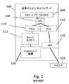
図1に、本明細書に開示するいくつかの実施形態に関連し得る機能及びモジュールを有するサーバなどのコンピュータシステム102の全体的アーキテクチャを示す。従来、(媒体104(例えば、回転媒体又はフラッシュ)などの、サーバ102上のローカルストレージ装置へのアクセスなどの)ストレージ機能と、転送などのネットワーク機能は、ソフトウェアスタック又は(例えば、ネットワーク機能又はストレージ機能のためにそれぞれネットワークインターフェイスコントローラ118又はストレージコントローラ112を伴う)ハードウェア装置のいずれかにおいて別個に行われていた。通常、(オペレーティングシステムと、実施形態によってはコンピュータシステムのストレージ機能及びネットワーク機能に関連する全てのソフトウェアスタックを含むハイパーバイザとを含むことができる)オペレーティングシステムスタック108内では、ソフトウェアストレージスタックが、スモールコンピュータシステムインターフェイス(SCSI)プロトコル、シリアルATA(SATA)プロトコル、又は不揮発性メモリエクスプレス(NVMe)プロトコル(典型的なコンピュータシステム102のPCIエクスプレス(PCIe)バス110を通じてソリッドステートドライブ(SSD)のようなディスク接続トストレージ(DAS)にアクセスするためのプロトコル)などの、ストレージ内で使用できる様々なプロトコルの使用を可能にするモジュールを含む。PCIeバス110は、((単複の)プロセッサ及びメモリを含む)CPU106と、様々なIOカードとの間を相互接続することができる。ストレージスタックは、ボリュームマネージャなどを含むこともできる。ストレージソフトウェアスタック内の動作は、ミラーリング又はRAID、バックアップ、スナップショット、重複排除、圧縮及び暗号化などのデータ保護を含むこともできる。ストレージ機能の一部は、ストレージコントローラ112内にオフロードすることができる。ソフトウェアネットワークスタックは、伝送制御プロトコル/インターネットプロトコル(TCP/IP)、ドメインネームシステムプロトコル(DNS)、アドレス解決プロトコル(ARP)及び転送プトロコルなどの様々なネットワークプロトコルの使用を可能にするためのモジュール及び機能などを含む。ネットワーク機能の一部は、イーサネット(登録商標)接続120などを介してネットワークインターフェイスコントローラ118(又はNIC)又はネットワークファブリックスイッチにオフロードし、(様々なスイッチ及びルータなどを用いて)さらにネットワークにつなげることができる。仮想環境では、PCIエクスプレス標準においてSR−IOVによって指定されるように、NIC118を複数の仮想NICに仮想化することができる。PCIエクスプレス標準によって指定されておらず、それほど一般的でもないが、ストレージコントローラも同様に仮想化することができる。仮想マシンなどの仮想エンティティは、この方法によって固有のプライベートリソースにアクセスすることができる。
FIG. 1 illustrates the overall architecture of a
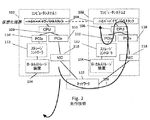
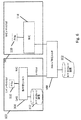
図2を参照すると、ハイパーバイザの1つの主要課題は、IO動作の複雑性である。例えば、2つの異なるコンピュータ(図2のコンピュータシステム1とコンピュータシステム2)にわたるデータに関与する動作に対処するには、コンピュータのローカルストレージ装置104、ストレージコントローラ112、CPU106、ネットワークインターフェイスコントローラ118及びハイパーバイザ/オペレーティングシステム108に関与する異なるソフトウェアスタック間をデータが移動する際にデータを幾度となく繰り返しコピーしなければならず、1つのコンピュータから別のコンピュータにデータを移すことや、或いはストレージの構成を変更することなどを伴う行動が行われる度に、IO動作毎に大量の非効率的なデータコピーが生じてしまう。ルート124は、データが2つのコンピュータのソフトウェアスタックを上下に移動して1つのコンピュータから別のコンピュータに至るまでに取ることができる多くの複雑なルート例の1つである。コンピュータシステム2が求めるデータは、当初はコンピュータシステム1のディスクなどのローカルストレージ装置104内に存在することがあり、この場合、ストレージコントローラカード112によってプルされ(IO動作及びコピーを伴い)、PCIeバス110(別のIO動作)を介してCPU108に送られ、ここでコンピュータシステム1のOSスタック108のハイパーバイザ又はその他のソフトウェアコンポーネントによって処理される。次に、このデータを、ネットワークコントローラ118を通じ、ネットワーク122を介して(別の一連のIO動作)コンピュータシステム2に送出(別のIO動作)することができる。このルートはコンピュータシステム2においても継続し、データは、ネットワークコントローラ118を通じてコンピュータシステム2のCPU106に移動した(さらなるIO動作を伴った)後に、PCIeバス110を介してストレージのローカルストレージコントローラ112に送られ、その後ハイパーバイザ/OSスタック108に戻されて実際に使用することができる。これらの動作は、数多くのコンピュータシステムの対にわたって行われ、各交換は、この種の大幅に増加したIO動作を伴う(また他の多くのルートも可能であり、それぞれが多くの動作を伴う)ことがある。企業が次第に採用してきているスケールアウトの状況では、コンピュータシステム間におけるこのような多くの複雑なデータ複製及び転送行為が必要である。例えば、MongoDB(商標)のようなスケールアウトアプリケーションを実装すると、顧客は、リバランス動作中にリアルタイムクエリを繰り返し実行して大規模なデータロードを行わなければならない。このような行為は、非常に多くのIO動作を伴い、ハイパーバイザソリューションの性能が低下してしまう。これらのアプリケーションのユーザは、頻繁にリシャーディング(データが配置されたシャードの変更)も行い、やはり1つの場所から別の場所へのデータの移動に数多くのIO動作を伴う多くのコピー動作及び転送動作が関与するので、静的ストレージリソース割り当てを行うベアメタルソリューションにとっての大きな問題となる。これらの問題は、スケールアウトアプリケーションにおいて使用されるデータ量が急速に増加し、(多くの機械を伴うクラウド展開などにおいて)異なるシステム間のつながりが増えるにつれて指数関数的に拡大する。IO動作の回数及び複雑性を低減し、高価なプレミアムハードウェアを必要とせずにスケールアウトアプリケーションの性能及び拡張性を別様に高めるストレージソリューション及びネットワーキングソリューションが必要とされている。
Referring to FIG. 2, one major challenge of the hypervisor is the complexity of IO operations. For example, to handle operations involving data across two different computers (
引き続き図2を参照すると、多くのアプリケーション及び使用事例では、コンピュータシステム102間のネットワークを越えてデータ(さらにはストレージ)にアクセスする必要がある。この動作の3つの高レベルステップは、一方のコンピュータシステムのストレージ媒体からボックス外にデータを転送し、ネットワーク122を越えて移動させ、第2のボックス(第2のコンピュータシステム102)内にデータを転送してこの第2のコンピュータシステム102のストレージ媒体104に移動させることを含む。まず、ボックス外転送は、ストレージコントローラ112からの介入、OS108内のストレージスタックからの介入、OS108内のネットワークスタックからの介入、及びネットワークインターフェイスコントローラ118からの介入を伴う可能性がある。内部バス(PCIe110及びメモリ)を横切る多くのトラバース及びコピー、並びにCPU106の処理サイクルが費やされる。これにより、動作性能が低下する(レイテンシ及びスループットの問題が生じる)だけでなく、CPU上で実行される他のアプリケーションにも悪影響が及ぶ。次に、データがボックス102から離れてネットワーク122上に移動すると、このデータは他のあらゆるネットワークトラフィックと同様に扱われ、その宛先に転送/ルーティングする必要がある。ポリシーが実行されて決定が行われる。大量のトラフィックが動いている環境では、ネットワーク122に輻輳が生じて性能の低下及び利用可能性問題(例えば、パケットの欠損、接続の喪失及び予測不能なレイテンシ)を引き起こす恐れがある。ネットワークは、一時停止機能、逆方向輻輳通知(BCN)、明示的輻輳通知(ECN)などの、輻輳の拡大を避けるための機構及びアルゴリズムを有する。しかしながら、これらは反応的方法、すなわち輻輳形成地点を検出し、発生源において先送りして輻輳を低減するものであり、結果として遅延及び性能への影響を生じる可能性がある。3番目に、データがその「宛先」コンピュータシステム102に到着すると、このデータを処理する必要があり、これにはネットワークインターフェイスコントローラ118からの介入、OS108内のネットワークスタックからの介入、OS108内のストレージスタックからの介入及びストレージコントローラ112からの介入が伴う。上述したボックス外動作と同様に、内部バスを横切る多くのトラバース及びコピー、並びにCPU106の処理サイクルが費やされる。さらに、データの最終目的地は、さらに異なるボックス内に存在することもある。このことは、より多くのデータ保護(例えば、ミラーリング又はボックス間RAID)の必要性、又は重複排除の必要性の結果と考えることができる。そうである場合、ネットワークを横切るボックス外及びボックス内へのデータ転送シーケンスを再び繰り返す必要がある。上述したように、この方法を制限するものとしては、本来の性能の低下、予測不能な性能、他のテナント又は動作への影響、利用可能性及び信頼性、並びに非効率的なリソース使用が挙げられる。現行方法の複雑性及び性能への影響を回避するデータ転送システムに対するニーズが存在する。
With continued reference to FIG. 2, many applications and use cases require access to data (and storage) across the network between
(管理する各仮想マシンに別個のオペレーティングシステムを提供する)ハイパーバイザの代案として、(単一のオペレーティングシステムによる複数のアプリケーションコンテナの管理を可能にする)Linux(登録商標)コンテナなどの技術が開発されてきた。また、アプリケーションをライブラリにパッケージングするプロビジョニングを提供するDockersなどのツールも開発されてきた。本開示全体を通じて説明する他の多くの技術革新の中でも特に、これらの新たな技術の能力を活用してスケールアウトアプリケーションのための改善された方法及びシステムを提供する機会が存在する。 As an alternative to a hypervisor (providing a separate operating system for each virtual machine to be managed), technologies such as Linux (registered trademark) containers (which enable management of multiple application containers by a single operating system) have been developed. It has been. Tools such as Dockers that provide provisioning to package applications into libraries have also been developed. Among many other innovations described throughout this disclosure, there is an opportunity to leverage these new technology capabilities to provide improved methods and systems for scale-out applications.
本明細書では、イニシエータ、ターゲットストレージ機能及びネットワーク機能を単一のデータ及び制御経路に組み合わせるハードウェアにおける集中型ストレージ及びネットワークコントローラを含み、ホストCPUによる介入を必要とせずにネットワークとストレージとの間の「カットスルー」経路を可能にする方法及びシステムを提供する。参照を容易にするために、本開示では、このソリューションを、集中型ハードウェアソリューション、集中型装置、集中型アダプタ、集中型IOコントローラ又は「データワイズ」コントローラなどと様々に呼ぶことができ、このような用語は、文脈において別途示している場合を除き、ターゲットストレージ機能とネットワーク機能とを単一のデータ及び制御経路に組み合わせるハードウェアにおける集中型ストレージ及びネットワークコントローラを含むものとして理解すべきである。 This document includes a centralized storage and network controller in hardware that combines initiator, target storage and network functions into a single data and control path, and does not require intervention by the host CPU. Methods and systems are provided that allow for a “cut-through” path. For ease of reference, this disclosure may refer variously to this solution as a centralized hardware solution, a centralized device, a centralized adapter, a centralized IO controller, or a “datawise” controller, etc. Such terms should be understood to include centralized storage and network controllers in hardware that combine target storage functions and network functions into a single data and control path, unless otherwise indicated in the context. .
この集中型ソリューションは、他の利点の中でも特に、コンピュータリソース及び/又はストレージリソースのクラスタのそのままの性能を高め、クラスタ全体にわたってサービスレベル合意(SLA)を強制するとともに予測可能な性能の保証に役立ち、テナントがその近隣に影響を与えないマルチテナント環境を提供し、ハードウェアの利用度が高いことによってデータセンタの占有面積が減少し、電力が減少し、管理すべきシステムが少なくなる、より高密度なクラスタを提供し、拡張性の高いクラスタを提供し、性能を損なうことなくクラスタ全体にわたってストレージソースをプールする。 This centralized solution, among other benefits, enhances the natural performance of a cluster of computer resources and / or storage resources, helps enforce service level agreements (SLA) across the cluster and guarantees predictable performance. Provide a multi-tenant environment where tenants do not affect their neighbors, and high utilization of hardware reduces the footprint of the data center, reduces power, and reduces systems to manage Provide dense clusters, provide highly scalable clusters, and pool storage sources across clusters without compromising performance.
本明細書に開示する様々な方法及びシステムは、スケールアウトアプリケーション及び高性能マルチノードプールに必要なリソースを高密度に圧密化する。これらの方法及びシステムは、動的なクラスタ規模のリソース提供、ネットワーク機能及びストレージ機能に対してサービス品質(QoS)、セキュリティ、分離などを保証する能力、並びに生産及び検査/開発のために共有インフラストラクチャを使用する能力を含む複数の顧客利益を提供する。 The various methods and systems disclosed herein compact the resources required for scale-out applications and high performance multi-node pools at high density. These methods and systems include dynamic cluster-scale resource provisioning, the ability to ensure quality of service (QoS), security, isolation, etc. for network and storage functions, as well as a shared infrastructure for production and inspection / development. Provide multiple customer benefits, including the ability to use structures.
また、本明細書では、ネットワークを通じたストレージ機能を実行し、ストレージ装置及びネットワーク装置を仮想化して単一テナント環境又はマルチテナント環境における高性能及び決定的性能をもたらす方法及びシステムも提供する。 The present specification also provides a method and system for performing storage functions over a network and virtualizing storage devices and network devices to provide high performance and deterministic performance in a single tenant environment or a multi-tenant environment.
また、本明細書では、NVMe及び同様のプロトコルを使用するようなストレージ装置を仮想化し、これらの仮想装置を、SATAを使用するような異なる物理的装置に変換する方法及びシステムも提供する。 The present specification also provides a method and system for virtualizing storage devices such as using NVMe and similar protocols and converting these virtual devices to different physical devices such as using SATA.
本明細書に開示する方法及びシステムは、ボックスレベルでの遠隔クレジット管理及び分散スケジューリングアルゴリズムを含むハードウェアを(ネットワークファブリックとは対照的に)ホスト側のみに含むエンドツーエンド輻輳制御のための方法及びシステムも含む。 The method and system disclosed herein is a method for end-to-end congestion control that includes only the host side (as opposed to the network fabric) hardware including remote credit management and distributed scheduling algorithms at the box level. And systems.
また、本明細書では、ストレージアダプタ、ネットワークアダプタ、コンテナ(例えば、Linux(登録商標)コンテナ)又はSolarisゾーンなどのクラスタを可能にするストレージクラスタ又はその他の要素の仮想化方法及びシステムを含む、集中型ネットワーク/ストレージコントローラによって可能になる様々な方法及びシステムも提供する。利点の中でも特に、クラスタを仮想化する1つの態様では、物理的クラスタ内でコンテナが位置に依存しないようにすることができる。他の利点の中でも特に、これにより、後述する大いに単純化されたプロセスにおけるマシン間のコンテナの移動が可能になる。 Also herein, a centralized, including storage cluster or other element virtualization method and system that enables clusters such as storage adapters, network adapters, containers (e.g., Linux (R) containers) or Solaris zones, etc. Various methods and systems are also provided which are enabled by the network / storage controller. Among other advantages, one aspect of virtualizing a cluster can make containers independent of location within a physical cluster. Among other advantages, this allows for the transfer of containers between machines in a greatly simplified process described below.
本明細書では、直接接続ストレージ装置(DAS)の仮想化方法及びシステムを提供することにより、たとえ物理ストレージ装置が移動して遠隔地に存在する場合でも、オペレーティングシステムスタック108がローカルな永続装置を探し求めるようになり、すなわち本明細書では、DASの仮想化方法及びシステムを提供する。実施形態では、この方法が、ファブリック全体にわたってDASを仮想化し、すなわちDASストレージシステムを選択し、ボックス外に移動させてネットワーク上配置することを含むことができる。実施形態では、この方法が、DASを任意の名前空間に分割することを含むことができる。実施形態では、オペレーティングシステムがこの仮想DASに、まるで実際のDASであるかのようにアクセスできるようになり、例えば、OS108がNVMeを介しPCIeバスを通じてアクセスすることができる。従って、本明細書では、(DASを含む)ストレージ装置を仮想化する能力を提供することにより、たとえ実際にはイーサネット(登録商標)などのネットワークプロトコルを介してストレージ装置にアクセスしている場合でも、OS108がこの仮想ストレージをDASと見なすようになり、従ってOS108は、ローカル物理ストレージ装置の場合に必要なことと異なることを行う必要はない。
In this specification, by providing a direct attached storage device (DAS) virtualization method and system, the
本明細書では、OS108を何ら修正する必要なくOS108に仮想DASを露出することを含む、ファブリック全体にわたってDASを提供する方法及びシステムを提供する。
The present specification provides a method and system for providing DAS across a fabric, including exposing a virtual DAS to
また、本明細書では、(ターゲットストレージシステムを参照する)ストレージアダプタの仮想化方法及びシステムも提供する。 The present specification also provides a storage adapter virtualization method and system (referring to a target storage system).
本明細書では、ストレージイニシエーションとストレージターゲットとを単一のハードウェアシステムに組み合わせる方法及びシステムを提供する。実施形態では、これらをPCIeバス110によって接続することができる。単一のルート仮想化機能(SR−IOV)を適用して、いずれかの標準的な装置を選択し、この装置を数百個ものこのような装置であるかのように機能させることができる。本明細書に開示する実施形態は、SR−IOVを用いて物理ストレージアダプタの複数の仮想インスタンスを生じることを含む。SR−IOVは、I/O機能を仮想化するPCIe標準であり、ネットワークインターフェイスに使用されてきたが、本明細書に開示する方法及びシステムは、SR−IOVをストレージ装置に使用するように拡張する。従って、本明細書では仮想ターゲットストレージシステムが提供される。
The present specification provides a method and system for combining a storage initiation and a storage target into a single hardware system. In the embodiment, these can be connected by the
実施形態は、スイッチフォームファクタ又はネットワークインターフェイスコントローラを含むことができ、本明細書に開示する方法及びシステムは、(ソフトウェア又はハードウェアのいずれかの)ホストエージェントを含むことができる。実施形態は、フロントエンドとバックエンドとの間で仮想化を分割することを含むことができる。 Embodiments can include a switch form factor or network interface controller, and the methods and systems disclosed herein can include a host agent (either software or hardware). Embodiments can include partitioning virtualization between the front end and the back end.
実施形態は、集中型ネットワーク及びターゲットストレージコントローラのための様々な展開地点を含むことができる。いくつかの実施形態では、集中型装置をホストコンピュータシステム102上に配置し、他の事例では、ディスクを別のボックスに動かす(例えばイーサネット(登録商標)によって、以下の様々なボックスを切り換えるスイッチに接続する)ことができる。仮想化にはレイヤが必要になる場合がある一方で、ストレージリソースとコンピュータリソースとを別個にスケーリングできるようにストレージを分離することができる。また、この時ブレードサーバ(すなわち、ステートレスサーバ)を可能にすることもできる。かつては高価なブレードサーバ及び接続されたストレージエリアネットワーク(SAN)を伴っていた設備を代わりにスイッチに接続することができる。実施形態では、この設備が、リソースがラックレベルで分割される「ラックスケール」アーキテクチャを含む。
Embodiments can include various deployment points for centralized networks and target storage controllers. In some embodiments, the centralized device is located on the
本明細書に開示する方法及びシステムは、様々なタイプの非DASストレージを集中型ネットワーキング/ターゲットストレージ装置内のDASとして仮想化する方法及びシステムを含む。実施形態では、ストレージシステムに対して様々なフロントエンドプロトコルを使用すると同時に、ストレージ装置をOSスタック108に対してDASとして露出して、DASとして望まれるあらゆるストレージを仮想化することができる。
The methods and systems disclosed herein include methods and systems for virtualizing various types of non-DAS storage as DAS in a centralized networking / target storage device. In embodiments, various front end protocols may be used for the storage system while simultaneously exposing the storage device as a DAS to the
本明細書に開示する方法及びシステムは、集中型ネットワーク/ストレージアダプタの仮想化を含む。トラフィックの観点から、システムを1つに組み合わせることができる。ストレージアダプタとネットワークアダプタとを組み合わせて仮想化に追加すれば大きな利点が得られる。すなわち、2つのPCIeバス110を含む単一のホスト102が存在する。PCIe110からルーティングを行うには、RDMAのようなシステムを用いて別のマシン/ホスト102に到達させることができる。これを別個に行った場合、ストレージのRDMAシステムとネットワークRDMAシステムとを別個に構成する必要がある。それぞれを結合して2つの異なる場所で構成する必要がある。集中型シナリオでは、これがRDMAであり、他のどこかに別のファブリックが存在するとすれば、ストレージとネットワーキングの組み合わせを用いてこれらの2つを単一ステップで構成できるので、QoSを構成するステップ全体がゼロタッチ処理である。すなわち、ストレージが分かれば、QoSをネットワーク上に別個に構成する必要はない。
The methods and systems disclosed herein include centralized network / storage adapter virtualization. From a traffic perspective, the systems can be combined into one. Adding storage adapters and network adapters to virtualization can provide significant advantages. That is, there is a
本明細書に開示する方法及びシステムは、ハードウェア内で、任意に集中型ネットワークアダプタ/ストレージアダプタアプライアンス内で具体化されるネットワーキング機能及びストレージ機能の仮想化及び/又は間接参照を含む。仮想化は、あるレベルの間接参照であり、プロトコルは、別のレベルの間接参照である。本明細書に開示する方法及びシステムは、多くのオペレーティングシステムがローカルストレージを処理するために使用するのに適したNVMeなどのプロトコルを、SAS、SATAなどの別のプロトコルに変換することができる。NVMeなどの一貫したインターフェイスをOS108に露出することができ、バックエンドでは、コスト効率の高いストレージ媒体であれば何にでも変換することができる。このことは、ユーザに価格上/性能上の利点を与える。コンポーネントが安い/速い場合には、これらのうちのいずれかのコンポーネントを接続することができる。バックエンドは、NVMeを含む何であってもよい。
The methods and systems disclosed herein include virtualization and / or indirection of networking and storage functions embodied in hardware, optionally in a centralized network adapter / storage adapter appliance. Virtualization is one level of indirection, and protocol is another level of indirection. The methods and systems disclosed herein can convert a protocol such as NVMe that is suitable for use by many operating systems to handle local storage to another protocol such as SAS, SATA. A consistent interface such as NVMe can be exposed to the
本明細書では、ネットワーク機能及びストレージ機能のための集中型データ経路を装置に含める方法及びシステムを提供する。別の実施形態は、ネットワーク機能及びストレージ機能のための集中型データ経路をスイッチに提供することができる。 The present specification provides a method and system for including centralized data paths for network and storage functions in a device. Another embodiment may provide the switch with a centralized data path for network and storage functions.
実施形態では、本明細書に開示する方法及びシステムが、ストレージ/ネットワークトンネリングを含み、ネットワークを介したストレージシステム間のトンネル経路は、ソースコンピュータ又はターゲットコンピュータのオペレーティングシステムを伴わない。従来のシステムには、別個のストレージ経路とネットワーク経路とが存在し、従ってストレージに遠隔的にアクセスするには、メモリ、I/Oバスなどとの間で大々的にコピーを行う必要があった。これらの2つの経路を統合するということは、ストレージトラフィックがネットワークの方に真っ直ぐ進むということである。各コンピュータのOS108は、ローカルディスクしか見ない。別の利点は、プログラミングの単純さである。ユーザは、SANを別個にプログラムする必要がなく、すなわち本明細書に開示する方法は、ワンステッププログラム可能なSANを含む。ゾーンの発見及び指定などを必要とせずに、暗号化、接続及び分離などを中央でプログラム的に行うことができる。
In embodiments, the methods and systems disclosed herein include storage / network tunneling, and the tunnel path between the storage systems over the network does not involve the operating system of the source or target computer. In the conventional system, there are separate storage paths and network paths, and therefore, to remotely access the storage, it has been necessary to make extensive copies between the memory, the I / O bus, and the like. Integrating these two paths means that the storage traffic goes straight towards the network. The
本明細書に開示する実施形態は、OS108がストレージ装置をローカルディスクとして見るようにストレージ装置をOS108に対して仮想化することを含むことができる。集中型システムは、本明細書に開示する方法及びシステムにおける間接参照のレベルによって、ストレージ媒体の位置だけでなくメディアタイプも隠すことができる。たとえ実際のストレージが遠隔地に存在し、及び/又はSANなどの異なるタイプのものであっても、OSには、ローカルディスクが存在することしか見えない。従って、ストレージが仮想化され、OS108及びアプリケーションを変更する必要はない。通常は複雑なストレージタイプを裏で構成するために必要な管理、階層化ポリシー、バックアップポリシー及び保護ポリシーなどを全て隠すことができる。
Embodiments disclosed herein can include virtualizing a storage device to
ストレージの仮想化のどこで間接参照を行うかを選択する方法及びシステムを提供する。いくつかの機能の仮想化は、ハードウェア(例えば、ホスト上のアダプタ、スイッチ、様々なハードウェアフォームファクタ(例えば、FPGA又はASIC))及びソフトウェアで行うことができる。本明細書に開示する方法及びシステムをホストマシン上、トップオブラックスイッチ上、又はこれらの組み合わせで展開するような異なるトポロジーを利用することができる。選択に通じる要因としては、使いやすさが挙げられる。ステートレスサーバを実行したいと望むユーザは、トップオブラックを好むと思われる。この方法を気にしないユーザは、ホスト上のコントローラを好むと思われる。 A method and system for selecting where to perform indirect reference in storage virtualization are provided. Virtualization of some functions can be done in hardware (eg, adapters, switches on the host, various hardware form factors (eg, FPGA or ASIC)) and software. Different topologies may be utilized such that the methods and systems disclosed herein are deployed on a host machine, on a top-of-rack switch, or a combination thereof. One of the factors leading to selection is ease of use. A user who wants to run a stateless server would prefer top-of-rack. Users who do not care about this method would prefer a controller on the host.
本明細書に開示する方法及びシステムは、NVMeオーバイーサネット(登録商標)の提供を含む。これらの方法は、装置間で使用されるトンネリングプロトコルの基礎になり得る。NVMeは、従来はローカルPCIeに進むように意図された好適なDASプロトコルである。本明細書に開示する実施形態は、イーサネット(登録商標)を介してNVMeプロトコルトラフィックをトンネリングすることができる。NVMe(不揮発性メモリエクスプレス)は、Linux(登録商標)及びWindowsにおいてPCIeベースのフラッシュストレージへのアクセスを提供するプロトコルである。このプロトコルは、従来のシステムで使用されているソフトウェアスタックを迂回することによって高性能をもたらす。 The methods and systems disclosed herein include the provision of NVMe over Ethernet. These methods can be the basis for tunneling protocols used between devices. NVMe is a preferred DAS protocol that was conventionally intended to go to local PCIe. Embodiments disclosed herein can tunnel NVMe protocol traffic over Ethernet. NVMe (Non-Volatile Memory Express) is a protocol that provides access to PCIe-based flash storage in Linux (registered trademark) and Windows. This protocol provides high performance by bypassing the software stack used in conventional systems.
本明細書に開示する実施形態は、仮想化されて動的に割り当てられたNVMeデバイスを提供することを含むこともできる。実施形態では、NVMeを重畳させることもできるが、NVMeデバイスを分割し、仮想化して動的に割り当てることもできる。実施形態では、ソフトウェア内にフットプリントは存在しない。オペレーティングシステムは、同じ状態を保つ(集中型ネットワーク/ストレージカードを小型ドライバ)。この結果、仮想ストレージは、直接接続されたディスクにように示されるが、このような装置をネットワークにわたってプールできる点が異なる。 Embodiments disclosed herein can also include providing virtualized and dynamically allocated NVMe devices. In the embodiment, NVMe can be superimposed, but an NVMe device can be divided, virtualized, and dynamically allocated. In an embodiment, there is no footprint in the software. The operating system stays the same (centralized network / storage card small driver). As a result, the virtual storage is shown as a directly connected disk, except that such devices can be pooled across the network.
本明細書では、ストレージエリアネットワーク(SAN)のような共有の利点と共に、直接接続ストレージ装置(DAS)の単純性を提供する方法及びシステムを提供する。本明細書に開示する様々な実施形態における各集中型アプライアンスはホストとすることができ、あらゆるストレージドライブは、特定のホストに固有のものでありながら(SAN又は他のネットワークアクセス可能ストレージと同様に)他のホストからも見えるようにすることができる。本開示のネットワーク/ストレージコントローラによって可能になる各ボックス内のドライブは、SANと同様に挙動する(すなわち、ネットワーク上で利用可能である)が、管理方法は大幅に単純である。ストレージ管理者がSANを構成する場合、典型的な企業では、「誰が何を見る」など、部門全体がSANのゾーン(例えば、ファイバチャネルスイッチ)を構成することがある。この知識は最初から組み込まれており、ユーザは、SANの管理者にSANを構成する作業を行うように依頼しなければならない。通常のレガシーなSANのアーキテクチャにはプログラマビリティーが存在しない。本明細書に開示する方法及びシステムは、ネットワーク上に存在するローカルユニットを提供するが、これらのローカルユニットは、ゾーン定義などのような複雑な管理ステップを踏む必要なく、引き続き自機のストレージにアクセスすることができる。これらの装置は、ネットワークとストレージの両方を認識することのみによってSANが行うことを実行することができる。従って、これらは、第1のプログラム的なSANを表す。 The present specification provides a method and system that provides the simplicity of a direct attached storage device (DAS) with the benefits of sharing, such as a storage area network (SAN). Each centralized appliance in the various embodiments disclosed herein can be a host, and every storage drive is unique to a particular host (as well as a SAN or other network accessible storage). ) It can be made visible to other hosts. The drives in each box enabled by the network / storage controller of the present disclosure behave like a SAN (ie, are available on the network), but the management method is much simpler. When a storage administrator configures a SAN, in a typical enterprise, the entire department may configure a SAN zone (eg, a Fiber Channel switch), such as “who sees what”. This knowledge is built in from the beginning, and the user must ask the SAN administrator to do the work of configuring the SAN. There is no programmability in the normal legacy SAN architecture. The methods and systems disclosed herein provide local units that exist on the network, but these local units can continue to be stored in their own storage without having to go through complex management steps such as zone definition. Can be accessed. These devices can only do what the SAN does by recognizing both the network and the storage. They therefore represent the first programmatic SAN.
本明細書に開示する方法及びシステムは、集中型ネットワーク及びストレージデータ管理を提供するハードウェアアプライアンスによって可能になる永続的でステートフルな離散的ストレージを含むことができる。 The methods and systems disclosed herein can include persistent stateful discrete storage enabled by a hardware appliance that provides centralized network and storage data management.
本明細書に開示する方法及びシステムは、仮想化のためのコンテナの使用をサポートするように適合された単一アプライアンスにおけるネットワークデータ及びストレージデータ管理の収束を含むこともできる。このような方法及びシステムは、新興的なものではあるがいくつかのさらなる利点を提供するコンテナエコシステムに対応する。 The methods and systems disclosed herein can also include convergence of network data and storage data management on a single appliance adapted to support the use of containers for virtualization. Such a method and system addresses a container ecosystem that is emerging but offers several additional advantages.
本明細書では、NVMeの仮想化を実装する方法及びシステムを開示する。どれほど多くのソースがどれほど多くの宛先に関連しているかに関わらず、ソースからのデータがハブに入る前に最初にシリアル化される限り、ハブは、指定された宛先に順にデータを分配する。そうだとした場合、DMAエンジンなどのデータトランスポートリソースを1回のみのコピーに低減することができる。この開示は、様々な使用シナリオを含むことができる。1つのシナリオでは、NVMe仮想機能(VF)について、これらが全て同じPCIeバスに接続された場合、どれほど多くのVFが構成されるかに関わらず、データはこのVFのプール内に順に到来し、従ってDMAエンジンは1つしか存在せず、(制御情報のため)1つのストレージブロックしか必要ない。別の使用シナリオでは、離散ディスク/コントローラのプールを有するディスクストレージシステムについて、物理的バス、すなわちPCIeからデータが生じた場合、データはこのディスクのプール内に連続して到来するので、プール内にどれほど多くのディスク/コントローラが存在するかに関わらず、DMAエンジンなどのトランスポートリソースをコントローラ毎に1つではなく1つのみに低減することができる。 Disclosed herein is a method and system for implementing NVMe virtualization. Regardless of how many sources are associated with how many destinations, as long as the data from the source is first serialized before entering the hub, the hub distributes the data to the specified destinations in order. If so, data transport resources such as a DMA engine can be reduced to a one-time copy. This disclosure can include various usage scenarios. In one scenario, for NVMe virtual functions (VFs), if they are all connected to the same PCIe bus, data arrives sequentially in this VF pool, regardless of how many VFs are configured, Therefore, there is only one DMA engine and only one storage block is needed (for control information). In another usage scenario, for a disk storage system with a pool of discrete disks / controllers, if data originates from the physical bus, ie PCIe, the data arrives continuously in this pool of disks, so in the pool Regardless of how many disks / controllers exist, transport resources such as DMA engines can be reduced to only one per controller instead of one.
様々な例示的かつ非限定的な実施形態によれば、装置が、物理的ターゲットストレージ媒体コントローラと、物理的ネットワークインターフェイスコントローラと、ストレージ媒体コントローラとネットワークコントローラとの間のゲートウェイとを含む集中型入力/出力コントローラを含み、ゲートウェイは、ストレージ媒体コントローラとネットワークインターフェイスコントローラとの間のストレージトラフィック及びネットワークトラフィックのための直接接続を提供する。 According to various exemplary and non-limiting embodiments, the apparatus includes a centralized input including a physical target storage media controller, a physical network interface controller, and a gateway between the storage media controller and the network controller. The gateway includes a / output controller and provides a direct connection for storage traffic and network traffic between the storage media controller and the network interface controller.
様々な例示的かつ非限定的な実施形態によれば、ストレージ装置の仮想化方法が、第1のストレージプロトコルでの命令に応答する物理ストレージ装置にアクセスするステップと、第1のストレージプロトコルと第2ストレージプロトコルとの間で命令を変換するステップと、第2のプロトコルを用いて物理ストレージ装置をオペレーティングシステムに提示することにより、オペレーティングシステムを使用するホストコンピュータシステムに対して物理ストレージ装置が局所的に存在するか、それとも遠隔的に存在するかに関わらず、物理ストレージ装置のストレージが動的に展開されるようにするステップとを含む。 According to various exemplary and non-limiting embodiments, a storage device virtualization method accesses a physical storage device that responds to an instruction in a first storage protocol, Converting the instruction between the two storage protocols and presenting the physical storage device to the operating system using the second protocol, thereby making the physical storage device local to the host computer system using the operating system. The storage of the physical storage device is dynamically expanded regardless of whether the storage is physically present or remotely located.
様々な例示的かつ非限定的な実施形態によれば、アプリケーション及びコンテナの少なくとも一方の移動を容易にする方法が、集中型ストレージ及びネットワーキングコントローラを提供して、ゲートウェイが、ホストコンピュータのオペレーティングシステムの介入を伴わずに装置のストレージコンポーネントとネットワーキングコンポーネントとの間のネットワーク及びストレージトラフィックのための接続を提供するステップと、少なくとも1つのアプリケーション又はコンテナを、集中型ストレージ及びネットワーキングコントローラによって制御されるターゲット物理ストレージ装置にマッピングすることにより、アプリケーション又はコンテナが別のコンピュータシステムに移動する際に、アプリケーション又はコンテナが、ターゲット物理ストレージが接続されたホストコンピュータのオペレーティングシステムの介入を伴わずにターゲット物理ストレージにアクセスできるようにするステップとを含む。 According to various exemplary and non-limiting embodiments, a method for facilitating the movement of at least one of an application and a container provides a centralized storage and networking controller, wherein a gateway is an operating system of a host computer. Providing a connection for network and storage traffic between the storage component and the networking component of the device without intervention, and at least one application or container to be controlled by the centralized storage and networking controller By mapping to a storage device, when an application or container moves to another computer system, the application or container And a step of target physical storage to access the target physical storage without operating system intervention connected host computer.
様々な例示的かつ非限定的な実施形態によれば、ネットワークのサービス品質(QoS)を提供する方法が、集中型ストレージ及びネットワーキングコントローラを提供して、ゲートウェイが、ホストコンピュータのCPU上で実行されるオペレーティングシステムの介入、ハイパーバイザの介入、又はその他のソフトウェアの介入を伴わずに装置のストレージコンポーネントとネットワーキングコンポーネントとの間のネットワークトラフィック及びストレージトラフィックのための接続を提供するステップと、集中型ストレージ及びネットワーキングコントローラによって処理されるストレージトラフィック及びネットワークトラフィックの少なくとも一方に基づいて、ホストコンピュータのCPU上で実行されるオペレーティングシステムの介入、ハイパーバイザの介入、又はその他のソフトウェアの介入を伴わずにストレージ及びネットワーキングコントローラが展開されたデータ経路を有するネットワークに関連する少なくとも1つのサービス品質(QoS)パラメータを管理するステップとを含む。 According to various exemplary and non-limiting embodiments, a method for providing network quality of service (QoS) provides a centralized storage and networking controller, wherein a gateway is executed on a CPU of a host computer. Providing a connection for network traffic and storage traffic between the storage and networking components of the device without any operating system intervention, hypervisor intervention, or other software intervention, and centralized storage And an operating system running on the CPU of the host computer based on at least one of storage traffic and network traffic processed by the networking controller Managing at least one quality of service (QoS) parameter associated with a network having a data path through which storage and networking controllers are deployed without system intervention, hypervisor intervention, or other software intervention. Including.
QoSは、帯域幅パラメータ、ネットワークレイテンシパラメータ、IO性能パラメータ、スループットパラメータ、ストレージタイプパラメータ及びストレージレイテンシパラメータのうちの1つ又は2つ以上などの様々なパラメータに基づくことができる。QoSは、集中型ストレージ及びネットワークコントローラを介してストレージによってサービスを受けるアプリケーション及びコンテナの少なくとも一方がホストコンピュータから別のコンピュータに移動する際に自動的に維持することができる。同様に、QoSは、集中型ストレージ及びネットワークコントローラを介してアプリケーション及びコンテナの少なくとも一方にサービスを提供する少なくとも1つのターゲットストレージ装置が第1の位置から別の位置又は複数の位置に移動する際に自動的に維持することができる。例えば、要件が増えた際にストレージニーズを満たすように、ストレージ装置をスケーリングし、或いは異なるストレージ媒体タイプを選択することができる。実施形態では、ネットワークトラフィックデータの暗号化、ストレージ装置内のデータの暗号化、又はこれらの両方などのセキュリティ機能を提供することができる。圧縮、保護レベル(例えば、RAIDレベル)、異なるストレージ媒体タイプの使用、グローバル重複排除、並びに目標復旧時点(RPO)及び目標復旧時間(RTO)の少なくとも一方を達成するためのスナップショット間隔などの様々なストレージ機能を提供することもできる。 QoS can be based on various parameters such as one or more of bandwidth parameters, network latency parameters, IO performance parameters, throughput parameters, storage type parameters, and storage latency parameters. QoS can be maintained automatically as at least one of the applications and containers served by the storage via the centralized storage and network controller moves from the host computer to another computer. Similarly, QoS is used when at least one target storage device serving a service and / or container via a centralized storage and network controller moves from a first location to another location or locations. Can be maintained automatically. For example, the storage device can be scaled or different storage media types can be selected to meet storage needs as requirements increase. Embodiments can provide security features such as encryption of network traffic data, encryption of data in the storage device, or both. Various, such as compression, protection level (eg, RAID level), use of different storage media types, global deduplication, and snapshot interval to achieve target recovery point (RPO) and / or target recovery time (RTO) It can also provide a storage function.
独立した図を通じて同一又は機能的に同様の要素を同じ参照番号によって示す、以下の詳細な説明と共に本明細書に組み込まれて本明細書の一部を成す添付図面は、様々な実施形態をさらに示し、本明細書に開示するシステム及び方法による全ての様々な原理及び利点を説明する役割を果たす。 The accompanying drawings, which are incorporated in and constitute a part of this specification, together with the following detailed description, identify the same or functionally similar elements through the independent drawings, by the same reference numerals. And serves to illustrate all the various principles and advantages of the systems and methods disclosed herein.
当業者であれば、図中の要素は単純性及び明確性を目的として示しており、必ずしも縮尺通りではないと理解するであろう。例えば、図中の要素には、本明細書に開示するシステム及び方法の実施形態をより良く理解する役に立つように他の要素に対して寸法を誇張しているものもある。 Those skilled in the art will appreciate that the elements in the figures are shown for simplicity and clarity and are not necessarily to scale. For example, some elements in the figures may be exaggerated in size relative to other elements to help better understand the embodiments of the systems and methods disclosed herein.
以下、添付図面及び添付書類を参照しながら本開示の様々な例示的かつ非限定的な実施形態を説明することによって本開示を詳細に説明する。しかしながら、本開示は多くの異なる形で具体化することができ、本明細書に示す例示的な実施形態に限定されると解釈すべきではない。むしろ、これらの実施形態は、本開示を徹底的なものとして当業者に本開示の概念を十分に伝えるように提供するものである。本開示の実際の範囲を確認するには、特許請求の範囲を参照すべきである。 The present disclosure will now be described in detail by describing various exemplary and non-limiting embodiments of the present disclosure with reference to the accompanying drawings and attached documents. However, the present disclosure can be embodied in many different forms and should not be construed as limited to the exemplary embodiments set forth herein. Rather, these embodiments are provided so that this disclosure will be thorough and will fully convey the concept of the disclosure to those skilled in the art. To ascertain the actual scope of the disclosure, reference should be made to the claims.
本明細書に開示するシステム及び方法による実施形態を詳細に説明する前に、これらの実施形態は、主に集中型ネットワーキング及びストレージに関連する方法ステップ及び/又はシステムコンポーネントの組み合わせの形で存在することを認められれたい。従って、当業者に容易に明らかになる詳細によって本開示が曖昧にならないように、図面には、必要に応じてこれらのシステムコンポーネント及び方法ステップを従来の記号によって表し、本明細書に開示するシステム及び方法の実施形態を理解することに関する特定の詳細のみを示している。 Before describing in detail embodiments according to the systems and methods disclosed herein, these embodiments exist primarily in the form of a combination of method steps and / or system components related to centralized networking and storage. I want to be acknowledged. Accordingly, in order not to obscure the present disclosure with details that will be readily apparent to those skilled in the art, the system components and method steps, where appropriate, are represented by conventional symbols in the drawings. And only certain details relating to understanding the method embodiments are shown.
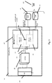
図3に示すように、集中型ソリューション300は、3つの重要な態様を含むことができ、ハードウェア、ソフトウェアモジュール及び機能の組み合わせを含むハードウェア装置で実装することができる。第1に、ネットワークコントローラ118とストレージコントローラ112の間にカットスルーデータ経路304を提供することにより、ストレージとネットワークとの間のアクセスを、OSスタック108、PCIeバス110又はCPU106のいずれの介入も必要とせずに直接的に行えるようにすることができる。第2に、ストレージとローカルホスト上のエンティティとの間のアクセスなどの、ストレージ装置302などへのカットスルーストレージスタックアクセスを提供して、ストレージにアクセスするためにSCSI/SAS/SATAスタックなどの複雑なレガシーソフトウェアスタックを迂回できるようにすることができる。第3に、ネットワークを横切るデータ転送を予約及びスケジュールする機構などによってネットワークのエンドツーエンド輻輳管理及びフロー制御を提供することにより、ターゲットのデータを遠隔イニシエータが利用できることを保証して、中間ネットワークファブリックスイッチを流れる際のトラフィックの輻輳を最小化することができる。第1及び第2の態様は、データ経路からソフトウェアスタック(従って、CPU106及びメモリ)を削除し、冗長又は不要な動き及び処理を排除する。エンドツーエンド輻輳管理及びフロー制御は、確定的で信頼性の高いデータ転送を提供する。
As shown in FIG. 3, the
上述したように、集中型ソリューション300の1つの利点は、オペレーティングシステムスタック108が従来のPCIe110又は同様のバスを介して集中型ソリューション300に接続することにより、たとえ物理ストレージが遠隔地に存在する場合でも、OSスタック108が、集中型ソリューション300と、ストレージ装置302へのカットスルーを通じて制御するあらゆるストレージとを1又は2以上のローカルな永続装置として見るようになる点である。とりわけ、この利点は、DAS308を仮想化する能力を含み、この能力は、ファブリックを介してDAS308を仮想化し、すなわちDAS308ストレージシステムを取り出し、コンピュータシステム102の外部に動かしてネットワーク上に置くことを含むことができる。集中型ソリューション300のストレージコントローラ112は、SAS、SATA又はNVMeなどの様々な既知のプロトコルを介してネットワーク122上のDAS308に接続して制御することができる。実施形態では、仮想化が、DAS308を任意の名前空間に分割することを含むことができる。実施形態では、オペレーティングシステムが、仮想DAS308に実際のローカル物理DASであるかのようにアクセスすることができ、例えばOS108が、NVMeなどの標準プロトコルを介し、PCIeバス110を介して集中型ソリューション300のストレージコントローラ112にアクセスすることができる。この場合も、OS108は、ソリューション300全体をDASなどのローカル物理装置として見る。従って、本明細書では、たとえ実際にはストレージがネットワーク122を介してアクセスされる場合でも、OS108があらゆるストレージタイプをDASと見なし、OS108がローカル物理ストレージの場合に必要とされる以外のことを行う必要がないようにする(DAS及びSAN310などの他のストレージタイプを含む)ストレージ仮想化能力を提供する。ストレージ装置302がSAN310ストレージである場合、集中型ソリューションのストレージコントローラ112は、インターネットスモールコンピュータシステムインターフェイス(iSCSI)、ファイバチャネル(FC)、又はファイバチャネルオーバイーサネット(登録商標)(FCoE)などのストレージエリアネットワークに使用するのに適したプロトコルを通じてSAN310を制御することができる。従って、集中型ソリューション300は、OSスタック108を、とりわけイーサネット(登録商標)、SAS、SATA、NVMe、iSCSI、FC又はFCoEなどのストレージにおいて使用されている他のプロトコルのいずれかから、異なるストレージタイプ及びプロトコルがPCIe110を介してアクセスできるローカルストレージのように見えるようにするNVMeのような単純なプロトコルに変換する。さらに、この変換は、(あらゆる種類のターゲットストレージシステムを参照する)ストレージアダプタの仮想化も可能にする。従って、本明細書に開示する方法及びシステムは、様々なタイプの非DASストレージを集中型ネットワーキング/ターゲットストレージ装置300内のDASとして仮想化する方法及びシステムを含む。実施形態では、ストレージシステムに対して様々なプロトコルを使用すると同時に、ストレージ装置をOSスタック108に対してDASとして露出して、DASとして望まれるあらゆるストレージを仮想化することができる。従って、本明細書では、NVMe及び同様のプロトコルを使用するようなストレージ装置を仮想化し、これらの仮想装置を、SATAを使用するような異なる物理装置に変換する方法及びシステムを提供する。
As described above, one advantage of the
ネットワーク122を介したストレージシステム間のトンネル経路がソース又はターゲットコンピュータのオペレーティングシステムに関与しないストレージ/ネットワークトンネリング304は、いくつかの利点を可能にする。従来のシステムには、別個のストレージ経路とネットワーク経路とが存在し、従ってストレージに遠隔的にアクセスするには、メモリ、I/Oバスなどとの間で大々的にコピーを行う必要があった。これらの2つの経路を統合するということは、ストレージトラフィックがネットワークの方に真っ直ぐ進むということである。プログラミングの単純さが利点である。ユーザは、SAN310を別個にプログラムする必要がなく、すなわち本明細書に開示する方法は、ワンステッププログラム可能なSAN310を可能にする。ゾーンの発見及び指定などを必要とせずに、構成、暗号化、接続及び分離などを中央でプログラム的に行うことができる。一例として、典型的なSANは、「イニシエータ」、「ターゲット」、及びイニシエータとターゲットとを接続するスイッチファブリックで構成される。通常、どのイニシエータがどのターゲットを見るかは、「ゾーン」と呼ばれるファブリックスイッチによって規定/制御される。従って、イニシエータ又はターゲットが移動した場合には、ゾーンを更新する必要がある。通常、SANの第2の制御部分は「ターゲット」と共に存在する。これらは、どのイニシエータポートがどの論理ユニット番号(LUN)(ターゲットによって露出されたストレージユニット)を見ることができるかを制御することができる。通常、この制御は、LUNマスキング及びLUNマッピングと呼ばれる。この場合も、イニシエータが移動した場合には「ターゲット」を再プログラムする必要がある。このような環境では、アプリケーションが(フェイルオーバ、ロードリバランシングなどに起因して)1つのホストから別のホストに移動した場合にゾーニング及びLUNマスキング/マッピングを更新する必要がある。或いは、全てのイニシエータが全てのターゲットを見るようにSANを予めプログラムしておくこともできる。しかしながら、これを行うと、SANをスケーリングできずセキュアでなくなる。本開示を通じて説明する別のソリューションでは、アプリケーション、コンテナ又はストレージ装置のこのような移動にSANの再プログラミングが必要なく、ゼロタッチソリューションとなる。集中型ソリューション300によって維持され実行されるマッピングは、アプリケーション又はコンテナ、ターゲットストレージ媒体、又はこれらの両方の、ホストCPU上で実行されるOS、ハイパーバイザ、又はその他のソフトウェアによる介入を伴わない(複数の位置を含めて)個別の移動及びスケーリングを可能にすることができる。
Storage /
OS108がストレージをローカルディスクとして見ることにより、ストレージの単純な仮想化が可能になる。集中型システム300は、本明細書に開示する方法及びシステムにおける間接参照のレベルによって、ストレージ媒体の位置だけでなくメディアタイプも隠すことができる。たとえ実際のストレージが遠隔地に存在し、及び/又はSAN310などの異なるタイプのものであっても、OS108には、ローカルディスクが存在することしか見えない。従って、集中型ソリューション300を通じてストレージが仮想化され、OS108及びアプリケーションを変更する必要はない。通常は複雑なストレージタイプを裏で構成するために必要な管理、階層化ポリシー、バックアップポリシー及び保護ポリシーなどを全て隠すことができる。
When the
集中型ソリューション300は、ストレージエリアネットワーク(SAN)の利点と共に、直接接続ストレージ(DAS)の単純性を可能にする。本明細書に開示する様々な実施形態における各集中型アプライアンス300はホストとして機能することができ、あらゆるストレージ装置302は、特定のホストに固有のものでありながら(SAN310又は他のネットワークアクセス可能ストレージと同様に)他のホストからも見えるようにすることができる。本開示のネットワーク/ストレージコントローラによって可能になる各ボックス内のドライブは、SAN310と同様に挙動する(例えば、ネットワーク上で利用可能である)が、管理方法は大幅に単純である。ストレージ管理者が通常通りにSANを構成する場合、典型的な企業では、「誰が何を見る」など、部門全体がSAN310のゾーン(例えば、ファイバチャネルスイッチ)を構成することがある。この知識は最初から組み込まれていなければならず、ユーザは、SANの管理者にSANを構成する作業を行うように依頼しなければならない。通常のレガシーなSAN310のアーキテクチャにはプログラマビリティーが存在しない。本明細書に開示する方法及びシステムは、ネットワーク上に存在するローカルユニットを提供するが、これらのローカルユニットは、ゾーン定義などのような複雑な管理ステップを踏む必要なく、引き続き自機のストレージにアクセスすることができる。これらの装置は、ネットワークとストレージの両方を認識することのみによってSANが行うことを実行することができる。従って、これらは、第1のプログラム的なSANを表す。
The
ソリューション300は、ストレージ媒体302及びネットワーク122の両方を制御する「集中型IOコントローラ」として説明することができる。この集中型コントローラ300は、ストレージコントローラ112とネットワークコントローラ(NIC)118とを単純に統合したものではない。実際のストレージ機能及びネットワーク機能は、ネットワークインターフェイスとの間をデータがトラバースする際にストレージ機能が実行されるように融合される。これら機能は、後述するFPGA(1又は2以上)又はASIC(1又は2以上)などのハードウェアソリューションにおいて提供することができる。
The
図4を参照すると、集中型ソリューション300によって可能になる2又は3以上のコンピュータシステム102は、それぞれのストレージターゲットのホストとしての役割を果たすことができ、ストレージとネットワークを融合して両インターフェイスを制御することにより、集中型ソリューション300によって可能になる別のコンピュータシステム102へのポイントツーポイント経路400又はイーサネット(登録商標)スイッチ402などによって内部バス又はCPU/ソフトウェアの機能をトラバースすることなく、ネットワーク122を介してストレージ装置302に遠隔的に直接アクセスすることができる。最高の性能(高IOP及び低レイテンシ)を達成することができる。さらに、この時点でクラスタ全体にわたってストレージリソース302をプールすることができる。図4には、このことを点線の楕円形400によって概念的に示している。
Referring to FIG. 4, two or
実施形態では、集中型ソリューション300を、図1に示すような従来のコンピュータシステムの様々なコンポーネント、及び図3に関して説明した集中型IOコントローラ300と共にホストコンピュータシステム102に含めることができる。図5を参照すると、別の実施形態では、集中型コントローラ300をトップオブラックスイッチなどのスイッチ内に配置し、従ってストレージ対応スイッチ500を可能にすることができる。このスイッチは、ネットワーク122上に存在することができ、従来のコンピュータシステム102のネットワークコントローラなどのネットワークコントローラ118によってアクセスすることができる。
In an embodiment, the
図6を参照すると、1又は2以上のホストコンピュータシステム102、並びに集中型ソリューション300によって可能になるシステム102と非可能システム102とに接続できるストレージ対応スイッチ500の両方に集中型コントローラ300が配置されたシステムを展開することができる。上述したように、ホストコンピュータシステム102及びストレージ対応スイッチ500における(単複の)集中型コントローラ300のためのターゲットストレージ302は、ネットワークを越えて互いに見えており、例えば仮想化ソリューションなどへの統一リソースとして扱われる。要するに、本開示の様々な別の実施形態におけるホストシステム、スイッチ、又はこれらの両方に、同じ装置上における集中型ネットワーク及びストレージトラフィックの処理を含む知性を配置することができる。
Referring to FIG. 6, a
従って、本明細書に開示する実施形態は、スイッチフォームファクタ又はネットワークインターフェイスコントローラを含むことができ、或いはこれらの両方は、(ソフトウェア又はハードウェアのいずれかの)ホストエージェントを含むことができる。これらの様々な展開は、ホスト上及び/又はスイッチ上、及び/又はフロントエンドとバックエンドとの間などにおける仮想化能力の分散を可能にする。いくつかの機能を仮想化するためにレイヤが必要になることもある一方で、ストレージリソースとコンピュータリソースとを別個にスケーリングできるようにストレージを分離することもできる。また、ブレードサーバ(すなわち、ステートレスサーバ)を可能にすることもできる。かつては高価なブレードサーバ及び接続されたストレージエリアネットワーク(SAN)を伴っていた設備を、代わりにストレージ対応スイッチ500に接続することができる。実施形態では、この設備が、リソースがラックレベルで分割される「ラックスケール」アーキテクチャを含む。
Thus, embodiments disclosed herein can include a switch form factor or network interface controller, or both can include a host agent (either software or hardware). These various deployments allow for the distribution of virtualization capabilities, such as on hosts and / or switches, and / or between front and back ends. While layers may be required to virtualize some functions, storage can also be separated so that storage resources and computer resources can be scaled separately. A blade server (ie, a stateless server) can also be enabled. A facility that was once accompanied by an expensive blade server and a connected storage area network (SAN) can be connected to the storage
ストレージの仮想化のどこで間接参照を行うかを選択する方法及びシステムを提供する。いくつかの機能の仮想化は、ハードウェア(例えば、ホスト102上の集中型アダプタ300、ストレージ対応スイッチ500、様々なハードウェアフォームファクタ(例えば、FPGA又はASIC))及びソフトウェアで行うことができる。本明細書に開示する方法及びシステムをホストマシン102上、トップオブラックスイッチ500上、又はこれらの組み合わせで展開するような異なるトポロジーを利用することができる。仮想化を行うべき場所の選択に通じる要因としては、使いやすさが挙げられる。ステートレスサーバを実行したいと望むユーザは、トップオブラックストレージ対応スイッチ500を好むと思われる。この方法を気にしないユーザは、ホスト102上の集中型コントローラ300を好むと思われる。
A method and system for selecting where to perform indirect reference in storage virtualization are provided. Virtualization of some functions can be done in hardware (eg,
図7は、2つのコンピュータシステム102(コンピュータシステム1及びコンピュータシステム2)を含む集中型コントローラ300と、ストレージ対応スイッチ500とを用いて可能になる1組のシステムのさらに詳細な図である。DAS308及びSAN310などのストレージ装置302は、集中型コントローラ300又はストレージ対応スイッチ500によって制御することができる。DAS308は、SASプロトコル、SATAプロトコル又はNVMeプロトコルのいずれかを使用する場合に制御することができる。SAN310は、iSCSI、FC又はFCoEのいずれかを使用する場合に制御することができる。ストレージコントローラ300を有するホスト102間の接続は、ポイントツーポイント経路400を介したもの、イーサネット(登録商標)スイッチ402を介したもの、又は従来のコンピュータシステムへの接続も提供できるストレージ対応スイッチ500を介したものとすることができる。上述したように、知的集中型コントローラ300を含む複数のシステムの各々は、ホストとしての役割と、他のホストが見るストレージターゲットロケーションとしての役割とを果たすことにより、コンピュータシステム102のオペレーティングシステム108のために単一のストレージクラスタとして取り扱われるオプションを提供することができる。
FIG. 7 is a more detailed view of a set of systems enabled using a
本明細書に開示する方法及びシステムは、ハードウェア集中型コントローラ300内で、任意に集中型ネットワークアダプタ/ストレージアダプタアプライアンス300内で具体化されるネットワーキング機能及びストレージ機能の仮想化及び/又は間接参照を含む。仮想化は、あるレベルの間接参照であり、プロトコルは、別のレベルの間接参照である。本明細書に開示する方法及びシステムは、多くのオペレーティングシステムがローカルストレージを処理するために使用するのに適したNVMeなどのプロトコルを、SAS、SATAなどの別のプロトコルに変換することができる。NVMeなどの一貫したインターフェイスをOS108に露出することができ、集中型コントローラ300の他方の側では、コスト効率の高いストレージ媒体302であれば何にでも変換することができる。このことは、ユーザに価格上/性能上の利点を与える。コンポーネントが安い/速い場合には、これらのうちのいずれかのコンポーネントを接続することができる。集中型コントローラ300の側は、NVMeを含むあらゆる種類のストレージに面することができる。さらに、ストレージ媒体タイプは、以下に限定されるわけではないが、HDD、(SLC、MLC又はTLCフラッシュベースの)SSD、RAM、その他、又はこれらの組み合わせのいずれかとすることができる。
The methods and systems disclosed herein provide for virtualization and / or indirection of networking and storage functions embodied in a hardware
実施形態では、集中型コントローラを、NVMe仮想機能を仮想化し、イーサネット(登録商標)スイッチ402を介してNVMeを通じてストレージ対応スイッチ500に接続されたような遠隔ストレージ装置302へのアクセスを提供するように適合させることができる。従って、集中型ソリューション300は、NVMeオーバイーサネット(登録商標)700、すなわちNVMeoEの使用を可能にする。従って、本明細書に開示する方法及びシステムは、NVMeオーバイーサネット(登録商標)の提供を含む。これらの方法は、集中型コントローラ300及び/又はストレージ対応スイッチ500によって可能になるホストコンピュータシステム102などの装置間で使用されるトンネリングプロトコルの基礎になり得る。NVMeは、従来ローカルPCIe110に進むように意図されている好適なDASプロトコルである。本明細書に開示する実施形態は、イーサネット(登録商標)を介してNVMeプロトコルトラフィックをトンネリングすることができる。NVMe(不揮発性メモリエクスプレス)は、Linux(登録商標)及びWindowsにおいてPCIeベースのフラッシュへのアクセスを提供するプロトコルである。このプロトコルは、従来のシステムで使用されているソフトウェアスタックを迂回することによって高性能をもたらすと同時に、イーサネット(登録商標)を介して他の装置にトンネリングされる(OSスタック108によって使用されるような)NVMe及びトラフィックを変換する必要性を回避する。
In an embodiment, the centralized controller virtualizes the NVMe virtual function and provides access to the
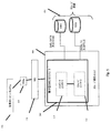
図8は、IOコントローラカード上に存在して集中型ソリューション300の実施形態を可能にすることができるFPGA800のブロック図である。なお、単一のFPGA800を示しているが、様々な機能ブロックは、複数のFPGA、1又は2以上の顧客特定用途向け集積回路(ASIC)などにまとめることもできる。例えば、別個の(ただし相互接続されている)FPGA又はASICにおいて、様々なネットワーキングブロック及び様々なストレージブロックを取り扱うことができる。本開示を通じて、FPGA800についての言及は、文脈によって別途示されている場合を除き、図8に反映する機能及び同様の機能を可能にすることができる他の形態ハードウェアも含むと理解されたい。また、ネットワーキング機能及び/又はストレージ機能などのいくつかの機能グループは、マーチャントシリコン内に具体化することもできる。
FIG. 8 is a block diagram of an
図8のFPGA800の実施形態は、4つの主なインターフェイスを有する。第1に、ホストコンピュータ102のPCIeバス110などへのPCIeインターフェイスが存在する。従って、このカードはPCIeエンドポイントである。第2に、DRAM/NVRAMインターフェイスが存在する。例えば、外部DRAM又はNVRAMに、組み込みCPU、メタデータ及びデータ構造、並びにパケット/データバッファリングによって使用されるDDRインターフェイスを提供することができる。第3に、DAS308及びSAN310などの、媒体へのストレージインターフェイスが存在する。ストレージインターフェイスは、SAS、SATA、NVMe、iSCSI、FC及び/又はFCoEのためのインターフェイスを含むことができ、実施形態では、SAN310のようなネットワーク対応ストレージに固有の、又はネットワーク対応ストレージへのカットスルーを介した、回転媒体、フラッシュ又はその他の永続的形態のストレージへのいずれかのインターフェイスとすることができる。第4に、ネットワークファブリックへのイーサネット(登録商標)などのネットワークインターフェイスが提供される。NVMeオーバイーサネット(登録商標)を可能にするには、ストレージインターフェイス及びネットワークインターフェイスを部分的に使用することができる。
The embodiment of
FPGA800の内部機能は、集中型ソリューション300のいくつかの有効化機能、及び全体を通じて説明する本開示の他の態様を含むことができる。ホストには、一連の仮想エンドポイント(vNVMe)802を提供することができる。これにより、ネットワークインターフェイスに使用されるSR−IOVプロトコルと同様に、ホストに仮想ストレージターゲットが提供される。このFPGA800の実施形態では、NVMeが低ソフトウェアオーバヘッドの利点を有し、これによってさらに高性能がもたらされる。仮想NVMeデバイス802には、割り当て/割り当て解除/移動及びサイズ変更を動的に行うことができる。SR−IOVと同様に、PCIeドライバ110(以下を参照)にインターフェイス接続する1つの物理的機能(PF)806と、各々がNVMeデバイスのように見える複数の仮想機能807(VF)とが存在する。
The internal functions of the
FPGA802の機能には、本明細書ではDMAエンジン804と呼ぶこともある1又は2以上の読み取り及び書き込み直接メモリアクセス(DMA)キュー804も提供される。これらは、割り込みキュー、ドアベル及びその他の標準機能を含んでホストコンピュータシステム102との間でDMAを実行することができる。
The functionality of
FPGA800の装置マッピング機構808は、仮想NVMeデバイス802の位置を特定することができる。この位置は、任意に局所的に存在する(すなわち、図示のストレージ媒体インターフェイス824の1つに接続される)ことも、或いはストレージコントローラ300の別のホスト102上に遠隔的に存在することもある。遠隔vNVMeデバイスにアクセスするには、トンネル828を通じてネットワーク122に進む必要がある。
The device mapping mechanism 808 of the
NVMe仮想化機構810は、NVMeプロトコル命令及び動作を、DAS308を使用する場合にはSAS又はSATAなどの(バックエンドストレージ媒体302のNVMeを使用する場合には変換は不要)、或いはバックエンドでSAN310ストレージを使用する場合にはiSCSI、FC又はFCoEなどの、バックエンドストレージ媒体302の対応するプロトコル及び動作に変換することができる。本明細書におけるバックエンドについての言及は、集中型コントローラ300のホスト102とは逆の側を意味する。
The NVMe virtualization mechanism 810 provides NVMe protocol instructions and operations such as SAS or SATA when using DAS 308 (no conversion required when using NVMe in the back-end storage medium 302), or
データ変換機能812は、ストレージ媒体302にデータが記憶された時に、このデータをフォーマットすることができる。これらの動作は、書き換え、変換、圧縮、(RAIDなどの)保護、暗号化、及び適用可能なタイプのターゲットストレージ媒体308によって処理されるために必要なあらゆる方法でのデータフォーマットの変更を含むその他の機能を含むことができる。いくつかの実施形態では、ストレージ媒体308が遠隔地に存在することができる。
The data conversion function 812 can format the data when it is stored in the
実施形態では、ストレージ読み取りキュー及び書き込みキュー814が、転送中の中継データのデータ構造又はバッファリングを含むことができる。実施形態では、(FPGA800から離れて存在ことができる)NVRAMのDRAMなどの一時ストレージ装置を使用してデータを一時的に記憶することができる。 In an embodiment, the storage read queue and write queue 814 may include the data structure or buffering of the relay data being transferred. In an embodiment, data may be temporarily stored using a temporary storage device such as NVRAM DRAM (which may be remote from FPGA 800).
ローカルストレージスケジューラ及びシェイパー818は、ストレージ媒体302へのアクセスを優先させて制御することができる。スケジューラ及びシェイパー818では、ストリクトプライオリティー、重み付きラウンドロビンスケジューリング、IOPシェイパー、並びにキュー毎、イニシエータ毎、ターゲット毎又はcグループ毎などに適用できるポリサーを含むことができる、ローカルストレージのためのあらゆる適用可能なSLAポリシーを実行することができる。
The local storage scheduler and shaper 818 can prioritize and control access to the
データ配置機構820は、ストレージ媒体302上でどのようにデータをレイアウトするかを決定するアルゴリズムを実装することができる。このアルゴリズムは、媒体全体にわたるストライピング、単一の装置302へのローカライジング、装置302のサブセットの使用、又は装置302の特定のブロックへのローカライジングなどの、当業者に周知の様々な配置スキームを伴うことができる。
Data placement mechanism 820 can implement an algorithm that determines how data is laid out on
ストレージメタデータ管理機構822は、データ配置、ブロックiノード及びオブジェクトiノード、圧縮、重複排除及び保護のためのデータ構造を含むことができる。メタデータは、FPGA800から離れたNVRAM/DRAM、又はストレージ媒体302のいずれかに記憶することができる。
The storage
複数の制御ブロック824は、ストレージ媒体へのインターフェイスを提供することができる。これらの制御ブロックは、他の考えられる制御ブロックの中でも特に、適当なタイプのターゲットストレージ媒体302に必要な場合毎に、SAS、SATA、NVMe、PCIe、iSCSI、FC及び/又はFCoEを含むことができる。
A plurality of control blocks 824 can provide an interface to the storage medium. These control blocks may include SAS, SATA, NVMe, PCIe, iSCSI, FC and / or FCoE, as needed for the appropriate type of
FPGA800のストレージネットワークトンネル828は、本開示を通じて集中型ソリューション300に関連して説明するトンネリング/カットスルー能力を提供することができる。とりわけ、トンネル828は、ストレージトラフィックとネットワークトラフィックとの間のゲートウェイを提供する。これには、カプセル化/脱カプセル化又はストレージトラフィック、データの書き換え及びフォーマット、及びデータ転送のエンドツーエンド調整が含まれる。この調整は、ホストコンピュータシステム102又は複数のコンピュータシステム102内の、図4に関連して説明したポイントツーポイント経路404などのためのノードを横切るFPGA800間の調整とすることができる。シーケンス番号、パケット喪失、タイムアウト及び再送信などの様々な機能を実行することができる。トンネリングは、FCoE又はNVMeoEによるものを含め、イーサネット(登録商標)を介して行うことができる。
The storage network tunnel 828 of the
仮想ネットワークインターフェイスカード機構830は、仮想ネットワークインターフェイスカードとして提供されるホスト102への複数のSR−IOVエンドポイントを含むことができる。1つの物理的機能(PF)836は、PCIeドライバ110(以下のソフトウェアの説明を参照)と、各々がネットワークインターフェイスカード(NIC)118のように見える複数の仮想機能(VF)837とに接続することができる。
The virtual network
一連の受信/送信DMAキュー832は、割り込みキュー、ドアベル及びその他の標準機能を含んでホスト102との間でDMAを実行することができる。
A series of receive / transmit DMA queues 832 may perform DMA with the
分類子及びフロー管理機構834は、典型的にはIEEE標準802.1Qサービスクラス(COS)マッピング、又はその他の優先順位レベルへの標準的なネットワークトラフィック分類を実行することができる。 The classifier and flow management mechanism 834 can typically perform standard network traffic classification to IEEE standard 802.1Q class of service (COS) mapping, or other priority level.
アクセス制御及び書き換え機構838は、典型的にはイーサネット(登録商標)タプル(MAC SA/DA、IP SA/DA、TCPポートなど)上でパケットの再分類又は書き換えを行うように動作するアクセス制御リストを含むアクセス制御リスト(ACL)及び書き換えポリシーに対処することができる。 The access control and rewrite mechanism 838 is typically an access control list that operates to reclassify or rewrite packets on Ethernet® tuples (MAC SA / DA, IP SA / DA, TCP port, etc.). Can handle access control lists (ACLs) and rewrite policies.
転送機能840は、レイヤ2(L2)又はレイヤ3(L3)機構などを通じてパケットの宛先を決定することができる。 The transfer function 840 can determine the destination of the packet through a layer 2 (L2) or a layer 3 (L3) mechanism.
一連のネットワーク受信及び送信キュー842は、データ構造又はネットワークインターフェイスへのバッファリングに対処することができる。パケットデータには、FPGA800から離れたDRAMを使用することができる。
A series of network receive and transmit queues 842 can handle buffering to data structures or network interfaces. For packet data, a DRAM remote from the
ネットワーク/リモートストレージスケジューラ及びポリサー844は、優先順位を提供してネットワークインターフェイスへのアクセスを制御することができる。ここでは、ストリクトプライオリティー、重み付きラウンドロビン、IOPシェイパー及び帯域幅シェイパー、並びにキュー毎、イニシエータ毎、ターゲット毎、Cグループ毎、又はネットワークフローベース毎などのポリサーを含むことができる、リモートストレージ及びネットワークトラフィックのためのSLAポリシーを実行することができる。 The network / remote storage scheduler and policer 844 can provide priority to control access to the network interface. Here, remote storage and can include strict priority, weighted round robin, IOP shaper and bandwidth shaper, and policers such as per queue, per initiator, per target, per C group, or per network flow base An SLA policy for network traffic can be implemented.
ローカルネットワークスイッチ848は、宛先がFPGA800又はホスト102に固有のものである場合、トラフィックがFPGA800から出てネットワークファブリック122に進まなくても済むように、FPGA内のキュー間でパケットを転送することができる。
The local network switch 848 may forward packets between queues in the FPGA so that traffic does not have to leave the
エンドツーエンド輻輳制御/クレジット機構850は、ネットワーク輻輳を防ぐことができる。この動作は、2つのアルゴリズムを用いて行われる。第1に、リモートFPGA800を含むエンドツーエンド予約/クレジット機構が存在することができる。この機構は、直ぐにデータを受け入れることができる場合にリモートFPGA800がストレージ転送を可能にするSCSI転送準備機能に類似することができる。同様に、FPGA800が転送を要求した場合、ローカルFPGA800は、リモートFPGA800にクレジットを割り当てる。ここでも、リモートストレージのためのSLAポリシーを実行することができる。第2に、Nick McKeown著、「入力キュースイッチのためのiSLIPスケジューリングアルゴリズム(The iSLIP Scheduling Algorithm for Input−Queues Switches)」、IEEE/ACM TRANSACTIONS ON NETWORKING 第7巻、第2号、1999年4月、において提案されている入力キューのためのiSLIPアルゴリズムなどの反復ラウンドロビンアルゴリズムなどの分散スケジューリングアルゴリズムが存在することができる。このアルゴリズムは、中間ネットワークファブリックをクロスバーとして用いてクラスタ全体にわたって実行することができる。
The end-to-end congestion control / credit mechanism 850 can prevent network congestion. This operation is performed using two algorithms. First, there can be an end-to-end reservation / credit mechanism that includes a
書き換え、タグ及びCRC機構852は、適当なタグ及びCRC保護を用いてパケットをカプセル化/脱カプセル化することができる。 The rewrite, tag and CRC mechanism 852 can encapsulate / decapsulate the packet with appropriate tag and CRC protection.
MACインターフェイスなどの一連のインターフェイス854は、イーサネット(登録商標)へのインターフェイスを提供することができる。
A series of
一連の組み込みCPU及びキャッシュコンプレックス858は、ローカルホスト及びネットワークリモートFPGA800との間でプロセス制御プラン、例外処理、及びその他の通信を実行することができる。
A series of embedded CPU and
DDRコントローラなどのメモリコントローラ860は、外部DRAM/NVRAMのコントローラとして機能することができる。 A memory controller 860 such as a DDR controller can function as an external DRAM / NVRAM controller.
本明細書では、FPGA800による1つの例において具体化される集中型ソリューション300によって提供される機能を統合した結果、ストレージの開始とストレージのターゲティングとを単一のハードウェアシステムに組み合わせる方法及びシステムを提供する。実施形態では、これらをPCIeバス110によって接続することができる。単一のルート仮想化機能(SR−IOV)などを適用し、いずれかの標準的な装置(例えば、いずれかのストレージ媒体302装置)を選択して数百個のこのような装置であるかのように機能させることができる。本明細書に開示する実施形態は、SR−IOVのようなプロトコルを用いて物理ストレージアダプタの複数の仮想インスタンスを生じることを含む。SR−IOVは、I/O機能を仮想化するPCIe標準であり、ネットワークインターフェイスに使用されてきたが、本明細書に開示する方法及びシステムは、SR−IOVをストレージ装置に使用するように拡張する。従って、本明細書では仮想ターゲットストレージシステムが提供される。実施形態では、仮想ターゲットストレージシステムが、異なる媒体をDAS310などの1又は複数のディスクであるかのように取り扱うことができる。
In the present specification, a method and system for combining storage initiation and storage targeting into a single hardware system as a result of integrating the functionality provided by the
本明細書に開示する方法及びシステムの実施形態は、実施形態によって可能になるFPGA800のように、仮想化されて動的に割り当てられたNVMeデバイスを提供することを含むこともできる。実施形態では、通常のNVMeプロトコルを重畳させることもできるが、NVMeデバイスを分割し、仮想化して動的に割り当てることもできる。実施形態では、ソフトウェア内にフットプリントは存在しない。オペレーティングシステム108は、同じ又はほぼ同じ状態を保つ(場合によっては、集中型ネットワーク/ストレージカード300を見る小型ドライバを有する)。この結果、仮想ストレージは、直接接続されたディスクにように見えるが、このようなストレージ装置302をネットワーク122にわたってプールできる点が異なる。
Embodiments of the methods and systems disclosed herein can also include providing virtualized and dynamically allocated NVMe devices, such as
本明細書では、NVMeの仮想化を実装する方法及びシステムを開示する。どれほど多くのソースがどれほど多くの宛先に関連しているかに関わらず、ソースからのデータがハブに入る前に最初にシリアル化される限り、ハブは、指定された宛先に順にデータを分配する。そうだとした場合、DMAキュー804、832などのデータトランスポートリソースを1回のみのコピーに低減することができる。この開示は、様々な使用シナリオを含むことができる。1つのシナリオでは、NVMe仮想機能(VF)について、これらが全て同じPCIeバス110に接続された場合、どれほど多くのVF807が構成されるかに関わらず、データはこのVFのプール807内に順に到来し、従ってDMAエンジン804は1つしか存在せず、(制御情報のため)1つのストレージブロックしか必要ない。
Disclosed herein is a method and system for implementing NVMe virtualization. Regardless of how many sources are associated with how many destinations, as long as the data from the source is first serialized before entering the hub, the hub distributes the data to the specified destinations in order. If so, data transport resources such as DMA queues 804 and 832 can be reduced to a one-time copy. This disclosure can include various usage scenarios. In one scenario, for NVMe virtual functions (VFs), if they are all connected to the
別の使用シナリオでは、離散ディスク/コントローラのプールを有するディスクストレージシステムについて、物理的バス、すなわちPCIe110からデータが生じた場合、データはこのディスクのプール内に連続して到来するので、プール内にどれほど多くのディスク/コントローラが存在するかに関わらず、DMAエンジン804などのトランスポートリソースをコントローラ毎に1つではなく1つのみに低減することができる。
In another usage scenario, for a disk storage system with a pool of discrete disks / controllers, if data originates from the physical bus,
本明細書に開示する方法及びシステムは、集中型ネットワーク/ストレージアダプタ300の仮想化を含むこともできる。トラフィックの観点から、システムを1つに組み合わせることができる。ストレージアダプタとネットワークアダプタとを組み合わせて仮想化に追加すれば大きな利点が得られる。すなわち、2つのPCIeバス110を含む単一のホスト102が存在する。PCIe110からルーティングを行うには、リモートダイレクトメモリアクセス(RDMA)のようなシステムを用いて別のマシン/ホスト102に到達させることができる。これを別個に行った場合、ストレージのRDMAシステムとネットワークRDMAシステムとを別個に構成する必要がある。それぞれを結合して2つの異なる場所で構成する必要がある。集中型ソリューション300では、これがRDMAであり、他のどこかに別のファブリックが存在するとすれば、ストレージとネットワーキングの組み合わせを用いてこれらの2つを単一ステップで構成できるので、QoSを構成するステップ全体がゼロタッチ処理である。すなわち、ストレージが分かれば、QoSをネットワーク上に別個に構成する必要はない。従って、集中型ソリューション300により、RDMAソリューションのためのネットワーク及びストレージのシングルステップ構成が可能になる。
The methods and systems disclosed herein may also include centralized network /
再び図4を参照すると、図8に関して説明したようなFPGA800又は同様のハードウェアによってリモートアクセスが可能になる。図4では、仮想化境界を点線408によって示している。この線よりも左側では、オペレーティングシステム108に仮想ストレージ装置(例えばNVMe802)及び仮想ネットワークインターフェイス830が示される。オぺレーティングシステムは、これらが仮想装置であることが分からない。仮想化境界408の右側には、(例えば、上述したSATA又はその他のプロトコルを使用する)物理ストレージ装置302及び物理的ネットワークインターフェイスが存在する。ストレージ仮想化機能は、図8のvNVMe802及びNVMe仮想化機構810によって実行される。ネットワーク仮想化機能は、vNIC機構830によって実行される。物理ストレージ媒体の位置も、オペレーティングシステム108から隠されている。サーバ全体にわたる物理的ディスク302をプールして遠隔的にアクセスできることが効率的である。オペレーティングシステム108は、ストレージ媒体302(このストレージ媒体302は仮想装置であるが、オペレーションシステム108は物理的装置として見る)に読み取り又は書き込みトランザクションを発行する。物理ストレージ媒体302がたまたま遠隔地に存在する場合、読み取り/書き込みトランザクションは、正しい物理的位置にマッピングされ、カプセル化され、イーサネット(登録商標)を通じてトンネリングされる。このプロセスは、図8の装置マッピング機構808、NVMe仮想化機構810、データ変換機構812及びストレージネットワークトンネル828によって実行することができる。ターゲットサーバ(第2のコンピュータシステム)は、ストレージ読み取り/書き込みをアントンネリングして、そのローカルストレージ媒体302に直接アクセスする。トランザクションが書き込みである場合、媒体302にデータが書き込まれる。トランザクションが読み取りである場合、データが準備され、オリジンサーバにマッピングされ、カプセル化され、イーサネット(登録商標)を通じてトンネリングされる。オリジンオペレーティングシステム102にトランザクション完了が到着する。従来のシステムでは、これらのステップが、ストレージ要求を処理するためのソフトウェアの介入、データフォーマット及びネットワークアクセスを必要とする。図示のように、これらの複雑なソフトウェアステップは全て回避される。
Referring again to FIG. 4, remote access is enabled by
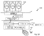
図9は、本開示を通じて説明する集中型ソリューション300の1つの実施形態としてのコントローラカード902のアーキテクチャの簡略ブロック図である。コントローラカード902は、例えば、Gen3×16カードなどの標準的なフルハイト、ハーフレングスのPCIeカードとすることができる。しかしながら、非標準的なカードサイズも容認可能であり、様々なタイプのターゲットシャーシに収まるようなサイズであることが好ましい。PCIeのフォームファクタは、PCB上で使用するスタックアップ及びレイヤを制限する。
FIG. 9 is a simplified block diagram of the architecture of a
コントローラカード902は、2RU、4ノードシャーシなどの汎用シャーシのアドオンカードとして使用することができる。シャーシの(スレッドと呼ばれる)各ノードの典型的な幅は、1RU及び6.76”である。通常、このマザーボードは、背面付近にPCIe Gen3×16コネクタを提供することができる。コントローラカード902は、ライザーカードを用いてマザーボードの上部に取り付けることができ、従ってカードとマザーボードの間の間隙は、概ねスロット幅に制限することができる。
The
実施形態では、PCIコネクタによって供給される最大電力が75Wである。コントローラカード902は、約60W以下を消費することができる。
In an embodiment, the maximum power supplied by the PCI connector is 75W. The
このシャーシは良好な空気流を提供することができるが、この例では、デュアルXeonプロセッサ及び16DIMMによって空気が温められるので、カードは、周囲温度が10℃上昇することを予想すべきである。ほとんどのサーバの最大周囲温度は35℃であり、従ってコントローラカード902における大気温度は、状況によっては45℃以上になる可能性がある。熱対策の一部として、カスタムヒートシンク及びバッフルを検討することができる。
Although this chassis can provide good airflow, in this example the air should be expected to increase by 10 ° C. because the air is warmed by the dual Xeon processor and 16 DIMMs. Most servers have a maximum ambient temperature of 35 degrees Celsius, so the ambient temperature in the
図9に示すコントローラカード902の実施形態には、データパスFPGA又はデータパスチップ904、及びネットワーキングFPGA又はネットワーキングチップ908という2つのFPGAを示している。
The
データパスチップ904は、PCIeコネクタ110を介したホストコンピュータ102への接続性を提供する。ホストプロセッサから見れば、コントローラカード902は複数のNVMeデバイスのように見える。データパスチップ904は、NVMeを標準的なSATA/SASプロトコルにブリッジし、この実施形態では、SATA/SASリンクを介して最大6個の外部ディスクドライブを制御する。なお、SATAは、最大6.0Gbpsをサポートし、SASは、最大12.0Gbpsをサポートする。
The data path chip 904 provides connectivity to the
ネットワーキングチップ908は、NICデバイス118の2つの10Gイーサネット(登録商標)ポート及びeCPU1018を2つの外部10Gイーサネット(登録商標)ポートに切り換える。ネットワーキングチップ908は、仮想化に使用する多くのデータ構造も含む。
The
通常、ホスト102のマザーボードは、Intelチップセット内の2つの別個のPCIe Gen3×8バスに分割できるPCIe Gen3×16インターフェイスを提供する。PCIe Gen3×8バス110の一方は、Intel NICデバイス118に接続される。第2のPCIe Gen3×8バス110は、PLX PCIeスイッチチップ1010に接続される。スイッチチップ1010のダウンストリームポートは、2つのPCIe Gen3×8バス110として構成される。バス110の一方は、eCPUに接続され、第2のバス110は、データパスチップ904に接続される。
Typically, the
データパスチップ904は、データストレージとして外部メモリを使用する。単一のx72DDR3チャネル1012は、ほとんどの状況にとって十分な帯域幅を提供すべきである。ネットワーキングチップ908も、データストレージとして外部メモリを使用し、単一のx72DDR3チャネルは、ほとんどの状況にとって十分と思われる。また、このデータ構造は、不揮発性DIMM(典型的には、データ保持用のエネルギ貯蔵要素としての内蔵電力切り替え回路及びスーパコンデンサを有するNVDIMM)などの、高性能及び十分な密度を提供するような不揮発性メモリの使用を必要とする。
The data path chip 904 uses an external memory as data storage. A single
eCPU1018は、2組のインターフェイスを用いてネットワーキング908と通信する。eCPU108は、NVMeと同様の通信のためのPCIe Gen2×4インターフェイスを有する。eCPU1018は、L2スイッチなどを介してネットワーキングチップ908に接続する2つの10Gイーサネット(登録商標)インターフェイスも有する。
The
2つのチップ904、908の内部設計全体を通じて、AXIバス1020(ARMチップセットのバス仕様)が使用される。AXIバス1020は、データパスチップ904とネットワーキングチップ908との間のシームレスな通信を可能にするためにチップ間接続に使用される。シリアルインターフェイスであるXilina Aurora(商標)プロトコルを物理的レイヤとして使用することができる。
Throughout the internal design of the two
FPGA構成の重要要件は、(1)PCIe構成の開始前にデータパスチップ904を準備する(QSPIフラッシュメモリ(4倍SPIバスインターフェイスを含むシリアルフラッシュメモリ)が十分に高速である)こと、及び(2)好ましくはチップがフィールドアップグレード可能であること、である。構成されるフラッシュメモリは、構成ビットストリームの少なくとも3つのコピーを記憶できるほど十分に大きいことが好ましい。このビットストリームは、Xilinx(商標)FPGAによって使用される構成メモリパターンを意味する。通常、ビットストリームは不揮発性メモリに記憶され、初期起動中にFPGAを構成するために使用される。eCPU1018は、構成フラッシュメモリの読み取り及び書き込みを行う機構を有することができる。ホスト102のプロセッサには、新たなビットストリームが存在することができる。eCPU1018は、フラッシュメモリをアップグレードしようと試みる前にセキュリティ及び認証に対処することができる。
The important requirements for FPGA configuration are: (1) Prepare the data path chip 904 before the start of the PCIe configuration (QSPI flash memory (serial flash memory with quadruple SPI bus interface) is fast enough), and ( 2) Preferably the chip is field upgradeable. The configured flash memory is preferably large enough to store at least three copies of the configured bitstream. This bitstream refers to the configuration memory pattern used by the Xilinx ™ FPGA. Typically, the bitstream is stored in non-volatile memory and is used to configure the FPGA during initial startup. The
ネットワーキングサブシステムでは、コントローラカード902が、ホストプロセッサと外部との間の全てのネットワークトラフィックを処理することができる。ネットワーキングチップ908は、NIC118及び外部からの全てのネットワークトラフィックを傍受することができる。
In the networking subsystem, the
この実施形態におけるIntel NIC118は、ネットワーキングチップ908に2つの10GigE XFIインターフェイス1022を接続する。組み込みプロセッサも同じことを行う。ネットワーキングチップ908は、L2スイッチング機能を実行して、2つの外部10GigEポートにイーサネット(登録商標)トラフィックを送出する。同様に、着信10GigEトラフィックは、NIC118、eCPU1018、又はネットワーキングチップ908の内部ロジックに直接進む。
The
コントローラカード902は、2つの外部10Gイーサネット(登録商標)ポートにSEP+光学コネクタを使用することができる。他の実施形態では、カードが、外部PHY及びRJ45コネクタを用いて10GBASE−Tをサポートすることができるが、SFP+とRJ45の切り換えを可能にするために別個のカード又はカスタムパドルカード構成が必要になり得る。
The
ネットワーキングチップ908は、LEDの動作を含む外部ポート及び光学素子の全ての管理を制御することができる。従って、PRST、I2C/MDIOなどの信号は、NIC108の代わりにネットワーキングチップ908に接続することができる。
The
ストレージサブシステムでは、データパスチップ904が、ミニSAS HDコネクタを直接駆動することができる。図10に示すような実施形態では、最新のSAD規格をサポートするように、信号を12Gbpsで動作するように設計することができる。 In the storage subsystem, the data path chip 904 can directly drive the mini-SAS HD connector. In an embodiment as shown in FIG. 10, the signal can be designed to operate at 12 Gbps to support the latest SAD standards.
ボードスペースを有効に使用するために、2つの×4ミニSAS HDコネクタを使用することができる。たとえ同時に6組の信号しか使用できない場合でも、8組の信号全てをデータパスチップ904に接続することができる。 Two x4 mini SAS HD connectors can be used to make efficient use of board space. Even if only 6 sets of signals can be used at the same time, all 8 sets of signals can be connected to the data path chip 904.
シャーシ上では、高速銅ケーブルを用いてミニSAS HDコネクタをマザーボードに接続することができる。ミニSAS HDコネクタの配置では、様々なシャーシの物理的スペース及びケーブルのルーティングを考慮することができる。 On the chassis, a mini SAS HD connector can be connected to the motherboard using a high speed copper cable. The placement of the mini SAS HD connector can take into account various chassis physical spaces and cable routing.
コントローラカード902への電力は、PCIe×16コネクタによって供給される。外部電源接続を使用する必要はない。PCI×16コネクタは、PCIe仕様により、電源投入後に最大25Wの電力しか供給することができない。コントローラカード902は、PCIeの構成後まで25W未満を引き出すように設計することができる。従って、初期電源投入後には、いくつかのインターフェイス及びコンポーネントをリセット状態に保持する必要がある。コネクタは、構成後に最大75Wの電力を供給することができ、75Wが3.3Vのレールと12Vのレールに分割されるように構成することができる。
Power to the
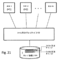
図10に、集中型ソリューション300にインターフェイス接続するドライバ1002を含む、FPGA800によって可能になるようなソフトウェアスタック1000を示す。NVMeコントローラ1004は、NVMeコントローラの機能を提供してホストに仮想装置1012を割り当てるハードウェア(例えば、FPGA800)の機能セットである。図10では、dev1、dev2、dev3が仮想装置1012の例であり、それぞれコンテナ1018LXC1、LXC2及びLXC3に動的に割り当てられる。NVMe−SATAブリッジ1008は、仮想装置1012(dev1、dev2、dev3)を変換してストレージ装置302(例えば、図のSSD)にマッピングするハードウェアサブシステム(例えば、FPGA800)の一部である。接続1010は、(上述した他の考えられる接続オプションから)SATA接続を提供するハードウェアシステムの一部である。イーサネット(登録商標)リンク120は、仮想装置1012(すなわち、dev1、dev2、dev3)を、ストレージトンネリングプトロコルを用いてイーサネット(登録商標)リンク120を介して接続された他の(単複の)ホスト102に露出することができる。PCI−E(NVMeドライバ)1002は、ストレージ側のハードウェアサブシステムをプログラムして駆動することができる。このドライバ1002は、ホスト上でオペレーティングシステム(例えば、この例ではLinux(登録商標)OS)の一部として実行することができる。ブロックレイヤ1014は、集中型ソリューションのPCIeドライバ1002にインターフェイス接続して仮想ストレージ装置1012を露出することができる、Linux(登録商標)オペレーティングシステムの従来のSCSIサブシステムとすることができる。コンテナ1018(LXC1、LXC2、LXC3)は、仮想ストレージ装置1012(それぞれdev1、dev2及びdev3)を要求してこれらに動的に割り当てることができる。
FIG. 10 illustrates a
図11〜図15に、複数のシステム102にわたるアプリケーションコンテナ1018(例えば、Linux(登録商標)コンテナ)の移動例を、最初に集中型ソリューション300が存在しない場合について、次に集中型ソリューション300が存在する場合について示す。図11には、従来のストレージコントローラ112と、OS/ハイパーバイザスタック108内の仮想ソフトウェアをホストするネットワークコントローラ118とを有する2つの従来のコンピュータシステム102の例を示す。コンピュータシステム1(C1)は、CPU、メモリ、従来のストレージコントローラ112及びネットワークコントローラ118を含む、図1に示すものと同様の構成を有する。このシステムは、Linux(登録商標)、Microsoft Windows(商標)などのオペレーティングシステム108、及び/又はXen、VMwareなどのハイパーバイザソフトウェアを実行して、ネイティブに又は仮想マシン又はコンテナなどの仮想環境を通じて複数のアプリケーションをサポートする。このコンピュータシステム102では、仮想マシンVM1 1104の内部でアプリケーションApp1 1102が実行される。仮想化コンテナLXC1 1110及びLXC2 1114内では、アプリケーションApp2 1108及びApp3 1112がそれぞれ実行される。これらのアプリケーションに加え、オペレーティングシステム108を通じてアプリケーションApp4 1118がネイティブに実行される。典型的なことではあるが、実際のシナリオでは、(3つ全てではなく)仮想マシン又はコンテナ又はネイティブアプリケーションのいずれかしか存在しないこともあり、ここでは仮想環境の全ての事例に対応するように意図的にこれらを組み合わせた形で示している。コンピュータシステム2(C2)102は、コンテナ内で及びネイティブにApp5及びApp6をそれぞれサポートする同様の構成を有する。これらのアプリケーションの各々は、互いに無関係にそれぞれのストレージ装置302にアクセスし、すなわちAPP1がS1を使用し、App2がS2を使用し、以下同様である。これらの(S1〜S6で示す)ストレージ装置302は、独立した物理エンティティに限定されるものではない。これらは、必要と認められる際には、1又は2以上の物理的ストレージ要素から論理的に分割することもできる。図示のように、(各ストレージ装置302からアプリケーションへの矢印によって示す)、ストレージ装置302とアプリケーション1102、1108、1112、1118との間のデータフローは、アプリケーションに到達する前にストレージコントローラ112及びオペレーティングシステム/ハイパーバイザスタック108を通過し、図1に関連して説明した課題を伴う。
FIGS. 11 to 15 show an example of moving an application container 1018 (for example, a Linux (registered trademark) container) across a plurality of
図12に示すように、アプリケーション又はコンテナがC1からC2に移動すると、その対応するストレージ装置も移動する必要がある。この移動が必要になり得る理由は、既存のアプリケーション(App1〜App4)内の挙動変化などに起因して、これらのアプリケーションをサポートするためのC1の(CPU、メモリなどの)リソースが一定期間にわたって不足している可能性があるからである。 As shown in FIG. 12, when an application or container moves from C1 to C2, the corresponding storage device also needs to move. The reason why this movement may be necessary is that the resources (such as CPU and memory) of C1 for supporting these applications have been used for a certain period due to behavior changes in existing applications (App1 to App4). This is because there may be a shortage.
通常は、アプリケーションの状態及びストレージのサイズが極端でない限り、十分な時間内に移動を行う方が容易である。一般に、ストレージ強化アプリケーションは大量(例えば、複数テラバイト)のストレージを使用することがあり、この場合には、許容時間内にストレージ302を移動させることが実際的でないこともある。この場合、図13に示すように、ストレージは相変わらず元の場所に留まり、ソフトウェアレベルの入れ替え/トンネリングを行ってストレージに遠隔的にアクセスすることができる。
Usually, it is easier to move within a sufficient amount of time unless the application state and storage size are extreme. In general, storage enhanced applications may use large amounts (eg, multiple terabytes) of storage, and in this case, it may not be practical to move the
図13に示すように、App2 1108は、コンピュータシステムC2に移動した後も、両システムC1及びC2のオペレーティングシステム又はハイパーバイザ108をトラバースすることにより、コンピュータシステムC1に位置する元々のストレージS2にアクセスし続ける。この理由は、ネットワークコントローラ118を介したストレージコントローラ112及びこれに接続されたストレージ装置302へのストレージアクセスのマッピングが、メインCPU内で実行されるオペレーティングシステム又はハイパーバイザソフトウェアスタック108によって行われるからである。
As shown in FIG. 13, after moving to the computer system C2,
図13に示すように、App2 1108は、C2に移動した後、両システムC1及びC2のオペレーティングシステム又はハイパーバイザ108をトラバースすることにより、C1に位置する元々のストレージS2にアクセスし続ける。この理由は、ネットワークコントローラ118を介したC2からC1への、さらにはC1のストレージコントローラ112へのストレージアクセスのマッピングが、各コンピュータシステムのメインCPU内で実行されるオペレーティングシステム又はハイパーバイザソフトウェア108によって行われるからである。
As shown in FIG. 13, after moving to C2,
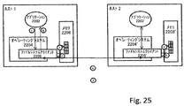
図14に示すように集中型コントローラ300を適用した場合の同様のシナリオについて検討する。図示のように、このシナリオは、別個のストレージコントローラ112及びネットワークコントローラ118が集中型IOコントローラ300に置き換わっている点を除いて図11とほぼ同一である。この場合、(図15に示すように)App2 1108がそのコンテナLXC1と共にC2に移動してもストレージS2は移動せず、コンピュータシステムC1内に存在するメインCPUにおいて実行されるいずれかのソフトウェア(オペレーティングシステム、ハイパーバイザ108、又は他のいずれか)がトラバースされるのを避けることによってアクセスが最適化される。
Consider a similar scenario when the
従って、本明細書では、ストレージ装置が存在するメインCPUを迂回する新規の方法を提供し、この方法はさらに、(a)複数のコンピュータシステムを横切ってストレージにアクセスする際のレイテンシ及び帯域幅を大幅に低減することができ、(b)ストレージが存在するマシンからアプリケーションを移動させる必要がある状況を大幅に単純化して改善する。 Accordingly, the present specification provides a new method for bypassing the main CPU in which the storage device exists, and this method further includes: (a) latency and bandwidth when accessing storage across multiple computer systems. (B) greatly simplify and improve the situation where applications need to be moved from the machine where the storage resides.
イーサネット(登録商標)ネットワークは、最善努力の原則で挙動し、従って本質的に損失が多くバースト性である。いずれのパケットも永久に失われる可能性があり、或いはバッファリングされて他のパケット共にバースト式で遅延して送出される可能性がある。一方で、典型的なストレージ中心のアプリケーションは損失及びバーストに敏感であり、ストレージトラフィックがいつイーサネット(登録商標)ネットワークを介して送信されるかが重要である。 Ethernet networks behave on a best effort basis and are therefore lossy and bursty in nature. Any packet can be lost forever, or it can be buffered and sent along with other packets in a bursty manner. On the other hand, typical storage-centric applications are sensitive to loss and bursts, and it is important when storage traffic is transmitted over an Ethernet network.
バス/ネットワークを介した従来のストレージアクセスは、信頼性の高い予測可能な方法で行われる。例えば、ファイバチャネルネットワークは、エンドシステムによって行われるアクセス数を制限するようにクレジットベースのフロー制御を採用する。そして、エンドシステムに与えられるクレジット数は、必要なレイテンシ及び帯域幅ニーズを満たす予測可能時間内にストレージ要求を受け取って満足させるのに十分なコマンドバッファをストレージ装置が有しているかどうかに基づく。以下の図に、SATA、ファイバチャネル(FC)、SCSI、SASなどの異なるタイプのバスが採用するいくつかのクレジットスキームを示す。 Conventional storage access via bus / network is performed in a reliable and predictable manner. For example, Fiber Channel networks employ credit-based flow control to limit the number of accesses made by end systems. The number of credits given to the end system is then based on whether the storage device has enough command buffers to receive and satisfy the storage request within a predictable time that meets the required latency and bandwidth needs. The following figure shows several credit schemes employed by different types of buses such as SATA, Fiber Channel (FC), SCSI, SAS.
図16に示すように、イーサネット(登録商標)ネットワークは、最善努力の原則で挙動し、従って本質的に損失が多くバースト性になりがちである。いずれのパケットも永久に失われる可能性があり、或いはバッファリングされて他の多くのパケットと共に輻輳誘導バーストの形で遅延して送出される可能性がある。典型的なストレージ集中のアプリケーションは損失及びバーストに敏感であり、ストレージトラフィックがいつバス及びイーサネット(登録商標)を介して送信されるかが重要であるため、これらは、整合性を維持するために信頼性の高い予測可能な方法で行われる。例えば、従来、ファイバチャネルネットワークは、エンドシステムによって同時に行われるアクセス数を制限するようにクレジットベースのフロー制御を採用する。エンドシステムに与えられるクレジット数は、必要なレイテンシ及び帯域幅用件を満たす予測可能時間内にストレージ要求を受け取って満足させるのに十分なコマンドバッファをストレージ装置302が有しているかどうかに基づくことができる。図16に、他のタイプのこのようなスキームの中でも特に、SATAバス1602、ファイバチャネル(FC)1604及びSCSI/SAS接続1608などの異なるタイプのバスが採用するクレジットスキームの一部を示す。
As shown in FIG. 16, Ethernet networks behave on a best-effort principle and are therefore prone to lossy and bursty in nature. Any packet can be lost forever, or it can be buffered and sent out with many other packets in the form of congestion-induced bursts. Typical storage intensive applications are sensitive to loss and burst, and these are important to maintain consistency as storage traffic is important when transmitted over the bus and Ethernet. Done in a reliable and predictable way. For example, traditionally, Fiber Channel networks employ credit-based flow control to limit the number of simultaneous accesses performed by end systems. The number of credits given to the end system is based on whether the
図示のように、例えばFCコントローラ1610は、FCベースのストレージ装置1612に送信を行う前に最大「N」個のストレージコマンドまでの固有のバッファリングを有することができるが、FC装置1612は、例えばこの例では「N」より大きくすることも、「N」と等しくすることも、又は「N」より小さくすることもできる「M」個という異なるバッファ制限を有することができる。典型的なクレジットベースのスキームは、ターゲットレベル(この例では、FC装置1602などのストレージ装置302のうちの1つがターゲットである)を用いてクレジットを集約し、これらのクレジットに関する情報が、ターゲット302にアクセスしようと試みている様々なソース(この例では、FCコントローラ1610などのコントローラがソースである)に伝播される。例えば、「N」のキュー深度を有するターゲットに2つのソースがアクセスしている場合、ソースに与えられるクレジットの合計は、いかなる時点においてもターゲットが「N」個よりも多くのコマンドを受け取らないように「N」を超えることはない。ソース間のクレジットの分配は任意とすることも、或いは様々なタイプのポリシー(例えば、コスト/価格設定又はSLAなどに基づく優先順位)に基づくこともできる。コマンド要求を満たすことによってキューが処理されると、必要に応じてソースにおいてクレジットを補充することができる。この種のクレジットベースのストレージアクセスに従うことにより、ターゲットのキューがどうしようもなくなることによって生じる損失を避けることができる。
As shown, for example, the FC controller 1610 can have unique buffering up to “N” storage commands before sending to the FC-based storage device 1612, In this example, there may be “M” different buffer limits that may be greater than “N”, equal to “N”, or less than “N”. A typical credit-based scheme aggregates credits using a target level (in this example, one of the
FCOE及びiSCSIなどのイーサネット(登録商標)を介した典型的なストレージアクセスは、ターゲット志向、クレジットベースのコマンドフルフィルメントを、イーサネット(登録商標)リンクを介した転送に拡張することができる。このような場合、これらは、ソース志向よりもむしろターゲット装置志向とすることができる。本明細書では、代わりにいずれの又はどの種類のソースがどれほど多くのクレジットを獲得するかに基づくことができる新たなクレジットベースのスキームを提供する。例えば、図17に示すように、ネットワークをストレージに直接インターフェイス接続させる上述の集中型ソリューション300は、マルチプレクサを用いて、ソース志向のクレジットベースのスケジューリングスキームをターゲット装置志向のクレジットベースのスキームにマッピングすることができる。
Typical storage access over Ethernet, such as FCOE and iSCSI, can extend target-oriented, credit-based command fulfillment to transfer over Ethernet links. In such cases, these can be target device oriented rather than source oriented. This document provides a new credit-based scheme that can instead be based on how much credit any or what kind of source will earn. For example, as shown in FIG. 17, the
図17に示すように、イーサネット(登録商標)上に4つのソースが存在し、2つのターゲットストレージ装置302が存在する。典型的なターゲット志向のクレジットベースのスキームは、(1ターゲット当たり1つの)2つのキュー、又は1ソース当たり2つの接続を各ターゲットに露出する。代わりに、図17に示すように、キュー(Q1、Q2、Q3、Q4)1702は1ソース当たりのものであり、マルチプレクサ(S)1708を横切って2つのターゲット志向キュー(Q5、Q6)1704にマッピング/多重化される。この種のソース志向のクレジットベースのスキームを採用することにより、ターゲットストレージ装置302の数に関わらずにアクセス帯域幅及び予測可能なアクセスレイテンシを保証することができる。一例として、1つのタイプのマルチプレクサは、Q1がそのソースによって圧倒されないように、Q1のキューサイズ「P」がQ5及びQ6の「L+M」を超えないことを確実にするものである。
As shown in FIG. 17, there are four sources on the Ethernet (registered trademark) and two
実施形態では、ストレージ装置302からデータブロックにアクセスできるようにする方法及びシステムについて説明する。具体的には、アプリケーションがそのデータにアクセスして特定の一連のアクセス要件を満たせるようにする新規方法について説明する。
In the embodiment, a method and system for making a data block accessible from the
本明細書で使用する「アプリケーション駆動型データストレージ」(ADS)は、アプリケーションに対するアプリケーションデータの記憶方法、アクセス方法、転送方法、キャッシュ方法及び分配方法に関してあらゆるアプリケーションに透明性をもたらすストレージを含む。ADSは、アプリケーションがこれらの個々の相を制御して特定のアプリケーションの特定のニーズに対応できるようにする。一例として、あるアプリケーションは、アプリケーション自体の複数のインスタンスと、ネットワークを越えて複数のLinux(登録商標)ノードにわたって拡散した複数のプロセスとを含むことができる。これらのプロセスは、これらの間で共有的又は排他的に複数のファイルにアクセスすることができる。これらのプロセスは、アプリケーションがこれらのファイルをどのように処理したいと望むかに基づいて、異なるファイル部分に頻繁にアクセスしたいと望み、クイックアクセス又は使い捨てを必要とすることができる。これらの基準に基づいて、必要時にキャッシュ及び/又はストレージの異なる階層の特定のファイル部分を迅速なアクセスのためにセッション毎又はファイル毎にプリフェッチ及び/又は保持したいと望むことができる。これらのアプリケーション固有の要件は、ファイルシステム全体のディスクストライピング、先読み連続ブロックのプリフェッチ、サーバ又はLRU又はFIFOベースのファイルコンテンツキャッシングにおける物理メモリの確保などの一般的な方法で満たすことができない。 As used herein, “application-driven data storage” (ADS) includes storage that provides transparency to any application in terms of how application data is stored, accessed, transferred, cached, and distributed to the application. ADS allows an application to control these individual phases to meet the specific needs of a specific application. As an example, an application may include multiple instances of the application itself and multiple processes spread across multiple Linux nodes across the network. These processes can access multiple files shared or exclusively between them. These processes may desire quick access to different file portions, and may require quick access or disposable, based on how the application wants to process these files. Based on these criteria, it may be desirable to prefetch and / or keep specific file portions of different tiers of cache and / or storage on a per session or per file basis for quick access when needed. These application specific requirements cannot be met by general methods such as disk striping across the file system, prefetching of prefetched contiguous blocks, securing physical memory in server or LRU or FIFO based file content caching.
アプリケーション駆動型データストレージI/Oは、単純にストレージエンティティのみに適応可能なものではない。アプリケーション駆動型データストレージI/Oは、ストレージスタック全体に複数の方法で影響を与える。まず、アプリケーション駆動型データストレージI/Oは、Linux(登録商標)ページングシステム、バッファリング、基本ファイルシステムクライアント、TCP/IPスタック、分類、QoS処理及びネットワーキングハードウェア及びソフトウェアによって提供されるパケットキューイングを含むアプリケーションが実行されているコンピュータノードのストレージI/Oスタックに影響を与える。次に、アプリケーションノードとそのストレージとを相互接続し、イーサネット(登録商標)セグメント、最適経路選択、スイッチのバッファリング、レイテンシに敏感なストレージトラフィックの分類及びQoS処理、並びにストレージI/Oに関連するインプロージョン問題を含むネットワーキングインフラストラクチャに影響を与える。また、基本ファイルレイアウト、冗長性、アクセス時間、様々なタイプのストレージ及びリモートリポジトリの階層化を含むファイルの観点からデータを記憶して維持するストレージインフラストラクチャにも影響を与える。 Application driven data storage I / O is not simply adaptable to storage entities only. Application driven data storage I / O affects the entire storage stack in several ways. First, application-driven data storage I / O includes packet queuing provided by the Linux (R) paging system, buffering, basic file system client, TCP / IP stack, classification, QoS processing and networking hardware and software This affects the storage I / O stack of the computer node on which the application including is executed. Next, interconnect the application nodes and their storage and relate to Ethernet segments, optimal routing, switch buffering, latency sensitive storage traffic classification and QoS processing, and storage I / O Affect networking infrastructure, including implication issues. It also affects the storage infrastructure that stores and maintains data in terms of files, including basic file layout, redundancy, access time, various types of storage and tiering of remote repositories.
本明細書に開示する方法及びシステムは、アプリケーションノード内の典型的なアプリケーションに影響を与える要素、及び集中型ソリューション300がいくつかの重要なアプリケーション要件に対処するためにステータクオーを変更する方法に関するものを含む。
The methods and systems disclosed herein relate to factors that affect a typical application within an application node, and how the
従来のLinux(登録商標)スタックは、汎用メモリ割り当て、プロセススケジューリング、ファイルアクセス、メモリマッピング、ページキャッシングなどの単純なビルディングブロックを含むことができる。これらは、Linux(登録商標)上で実行されるアプリケーションにとって必須であるが、NoSQLなどの入力/出力(IO)集中的な特定のカテゴリのアプリケーションにとっては最適でない。NoSQLアプリケーションは非常にIO集中的であり、そのデータアクセスを一般的な方法で予測することは困難である。ユーティリティコンピュータ環境内でアプリケーションを展開する必要がある場合、Linux(登録商標)がこれらのビルディングブロックの汎用最小実装を提供することは理想的でない。これらのビルディングブロックは、非常にフレキシブルであるとともに、(単複の)アプリケーションから制御可能なアプリケーション関連の特徴を有することが好ましい。 A conventional Linux stack can include simple building blocks such as general memory allocation, process scheduling, file access, memory mapping, page caching, and the like. These are essential for applications running on Linux, but are not optimal for certain categories of input / output (IO) intensive applications such as NoSQL. NoSQL applications are very IO intensive and it is difficult to predict their data access in a general way. If applications need to be deployed within a utility computer environment, it is not ideal for Linux to provide a general minimum implementation of these building blocks. These building blocks are preferably very flexible and have application-related features that can be controlled from the application (s).
全てのアプリケーションは独自の特定の要件を有するが、例示的な実施形態では、アプリケーションのNoSQLクラスが、Linux(登録商標)スタックによって処理された時にNoSQLアプリケーション及びその他のIO集中的アプリケーションの性能を大幅に向上させる以下の要件を有する。まず、これらの要件は、ファイルレベル優先順位を使用する点である。Linux(登録商標)ファイルシステムは、最低限でも異なるファイル間でのアクセスレベル優先順位を提供すべきである。例えば、(他方よりも優先順位の高いデータベース/テーブル/インデックスなどの)一方が他方よりも高い優先順位を与えられた2つの異なるファイルにアクセスする(複数のスレッドからなる)アプリケーションプロセス。このプロセスでは、アクセスされるデータに基づいて貴重なストレージI/Oリソースを優先的に利用することができる。これには、1つのスレッド/プロセスを高優先順位又は低優先順位で実行することによって間接的に対処できるとの主張があると思われるが、これらのプロセスレベルの優先順位は、ファイルシステム又はストレージコンポーネントに通信されない。プロセス又はスレッドレベルの優先順位は、CPUリソースの利用のみを対象とする。さらに、これらの2つのファイルに同じスレッドがアクセスし、従ってどのデータ(ファイル)がアクセスされているに基づいて2つの異なるレベルでストレージソースを利用することも可能である。次に、アクセスレベルのプリファレンス要件が存在することもできる。Linux(登録商標)ファイルシステムは、ファイル(オープンファイル)のセッション中に、ファイルセッション間の優先順位、ブロックのバッファリング量、様々なブロックの保持/有効期限プリファレンス、リソース閾値及び競合のためのアラート、並びに性能統計などの様々なプリファレンス(主にSLA)を提供することができる。一例として、MongoDB又はCssandraなどのNoSQLアプリケーションが、書き込み及び読み取りのための2又は3以上のスレッドを有している時に、読み取りよりも書き込みのプリファレンスの方が高い場合、同じファイルの読み取りファイルセッションよりも書き込みファイルセッションの方に高プリファレンスを与える必要があり得る。この能力により、同じファイルの2つのセッションが、2つの異なる優先順位を有することができる。 Although all applications have their own specific requirements, in the exemplary embodiment, the performance of NoSQL applications and other IO-intensive applications is greatly enhanced when the application's NoSQL class is processed by the Linux stack. Have the following requirements to improve: First, these requirements are to use file level priority. The Linux® file system should provide access level priorities between at least different files. For example, an application process (consisting of multiple threads) that accesses two different files, one of which has a higher priority than the other (such as a higher priority database / table / index). This process allows preferential use of valuable storage I / O resources based on the data being accessed. There seems to be an assertion that this can be addressed indirectly by running a single thread / process at high or low priority, but these process level priorities are either file system or storage The component is not communicating. Process or thread level priorities target only the use of CPU resources. In addition, it is possible to use the storage source at two different levels based on which data (file) is accessed by the same thread accessing these two files. Next, an access level preference requirement may exist. The Linux (R) file system is used during file (open file) sessions for priority between file sessions, amount of block buffering, various block retention / expiration preferences, resource thresholds and contention. Various preferences (mainly SLA) such as alerts as well as performance statistics can be provided. As an example, if a NoSQL application, such as MongoDB or Csandra, has two or more threads for writing and reading, if the writing preference is higher than reading, the same file read file session It may be necessary to give higher preferences to the write file session than to. This capability allows two sessions of the same file to have two different priorities.
NoSQLアプリケーションの多くは、異なるタイプのデータを同じファイルに記憶し、例えばMongoDBは、ユーザコレクション及び(bツリー)インデックスコレクションを同じデータベースファイルの組に記憶する。MongoDBは、インデックスページ(bツリー及びコレクション)をユーザコレクションページよりも優先してメモリに保持しておきたいと望むことができる。MongoDBは、これらのファイルがオープンになると、Linux(登録商標)、ファイル及びストレージシステムに影響を与えて、アプリケーションの要件を知らない汎用FIFO又はLRUに基づいてページを処理するのとは対照的に、MongoDBポリシーに従ってこれらのページを処理したいと望むことができる。 Many NoSQL applications store different types of data in the same file, for example MongoDB stores user collections and (b-tree) index collections in the same set of database files. MongoDB may wish to keep index pages (b-trees and collections) in memory in preference to user collection pages. MongoDB affects Linux, file and storage systems when these files are opened, as opposed to processing pages based on generic FIFOs or LRUs that do not know the requirements of the application. You may wish to process these pages according to the MongoDB policy.
リソースアラート及び性能統計は、NoSQLデータベースが基本ファイル及びストレージシステムの挙動を理解できるようにし、これに従ってデータベースクエリにサービスを提供し、或いはデータベースシャーディング、又は同じホストにおいて実行される(バックアップ、シャーディング、ナンバー読み取り/書き込みクエリサービスなどの)他のジョブのファイルI/Oプリファレンスの減分/増分などの実行すべき動作をトリガすることができる。例えば、IOP及びレイテンシの最小数、最大数及び平均数、並びに一定時間にホストメモリとの間でスラッシュイン及びスラッシュアウトされた上位10個の候補ページに関する性能統計は、アプリケーションが上述したパラメータを動的に調整してアプリケーション自体を微調整できるようにする。 Resource alerts and performance statistics enable the NoSQL database to understand basic file and storage system behavior and serve database queries accordingly, or database sharding or run on the same host (backup, sharding Trigger actions to be performed, such as decrementing / incrementing file I / O preferences of other jobs (such as number read / write query service). For example, the minimum, maximum and average number of IOPs and latencies, and performance statistics for the top 10 candidate pages slashed in and out of host memory over a period of time can be used to change the parameters described above by the application. To make fine adjustments to the application itself.
キャッシング及び階層化プリファレンスのための要件も存在することができる。Linux(登録商標)ファイルシステムは、アプリケーションがそのファイルにアクセスしている間に動的に構成可能なキャッシングポリシーを有する必要があり得る。通常、現在のLinux(登録商標)ファイルシステムは、アプリケーションがストリームのような連続的方法でファイルを読み取ることを希望して連続ファイルブロックをプリフェッチする。しかしながら、実際には、ウェブサーバ及びビデオストリーマのような多くのレガシーアプリケーションの場合、台頭しつつあるNoSQLアプリケーションは厳密に連続読み取りに従わない。これらのアプリケーションは、ブロックをランダムに読み取る。一例として、MongoDBは、キーの検索時にキーを発見するまでランダムにブロックにアクセスする、ファイルの一部にフラットにレイアウトされたbツリーの形でインデックステーブルにドキュメントキーを記憶する。さらに、これらのファイルは、このようなbツリーベースのインデックステーブル専用のものではない。これらのファイルは、ユーザドキュメント及びシステムインデックスファイルなどの様々なタイプのテーブル(コレクション)間で共有される。このため、Linux(登録商標)ファイルシステムは、効率的なメモリ使用などのために、ファイルのどの部分をキャッシュし、先読みし、スワップアウトする必要があるかを予測することができない。 There may also be requirements for caching and tiering preferences. The Linux file system may need to have a caching policy that can be dynamically configured while an application is accessing the file. Typically, current Linux file systems prefetch consecutive file blocks in the hope that an application reads the file in a continuous manner such as a stream. In practice, however, for many legacy applications such as web servers and video streamers, the emerging NoSQL applications do not strictly follow continuous reading. These applications read blocks randomly. As an example, MongoDB stores document keys in an index table in the form of a b-tree laid out flat in a portion of the file that randomly accesses the block until it finds the key when searching for the key. Furthermore, these files are not dedicated to such b-tree based index tables. These files are shared between various types of tables (collections) such as user documents and system index files. For this reason, the Linux (registered trademark) file system cannot predict which part of the file needs to be cached, prefetched, and swapped out for efficient memory usage and the like.
本明細書に開示する方法及びシステムの実施形態では、ストレージ要件において様々なアプリケーションにわたる共通スレッドが存在する。具体的には、特定の必要な時点及び場所における特定のタイプのデータのレイテンシ及びIOPは、これらのアプリケーションの性能に対して非常に強い影響力を有する。 In the method and system embodiments disclosed herein, there is a common thread across various applications in storage requirements. Specifically, the latency and IOP of a particular type of data at a particular required point in time and location has a very strong impact on the performance of these applications.
例えば、本明細書では、上述したホストレベルの要件に対処するために、アプリケーションがホスト内及び他の場所におけるプリファレンスに従ってデータの記憶、検索、保持及び階層化に完全に影響を与えてこれらを制御できるようにする十分に微調整されたファイルシステムクライアントのための方法及びシステムを開示する。 For example, in this document, to address the host level requirements described above, applications can completely influence the storage, retrieval, retention, and tiering of data according to preferences in the host and elsewhere. Disclosed are methods and systems for fully fine-tuned file system clients that allow control.
図18に示すように、ファイルシステム(FS)クライアント1802は、別個のファイルセッション(fd1及びfd2)のために別個のバッファプールを保持する。ファイルシステム(FS)クライアント1802は、アプリケーション又は一連のプロセス毎に集約メモリプールの事前割り当て及び維持も行う。SLAブローカ1804は、ファイルI/Oが実行されたプロセス/スレッド内で内部的に、又は別の一連のプロセスから外部的にアプリケーションが実行して、FSクライアント1802に影響を与えて適切なストレージI/O SLAを動的に提供することができる。SLAを外部プロセスから制御すると、アプリケーション自体を修正することなく、これらの新たなストレージ制御機能についての知識を有していないレガシーアプリケーションが直ちに可能になる。 As shown in FIG. 18, the file system (FS) client 1802 maintains separate buffer pools for separate file sessions (fd1 and fd2). The file system (FS) client 1802 also preallocates and maintains an aggregate memory pool for each application or series of processes. The SLA broker 1804 is executed by an application internally in the process / thread in which the file I / O is executed, or externally from another series of processes, and affects the FS client 1802 so that the appropriate storage I / O SLA can be provided dynamically. Controlling the SLA from an external process immediately enables legacy applications that do not have knowledge of these new storage control functions without modifying the application itself.
本明細書に開示する方法及びシステムは、ネットワーク及びホストを横切るデータ検索のための広範にわたる階層化サービスを提供することができる。以下の図19に示すように、高性能分散ファイルサーバ(DFS)1902は、キャッシュ形態ストレージ形態のどの媒体(DRAM、NVRAM、SSD又はHDD)にファイルのどの部分が存在すべきかを動的に決定して実行するようにプラットフォーム1904内でアプリケーションがコンテナ化された形で実行されることを可能にする。これらのアプリケーションコンテナ1908は、ファイルのストライピング、ミラーリング、レイディング及び障害回復(DR)を行う必要があるかどうかなどの他のストレージポリシーを決定することができる。 The methods and systems disclosed herein can provide a wide range of layered services for data retrieval across networks and hosts. As shown in FIG. 19 below, the high-performance distributed file server (DFS) 1902 dynamically determines which part of the file (DRAM, NVRAM, SSD, or HDD) in the cache storage form should exist. Application within the platform 1904 to be executed in a containerized manner. These application containers 1908 can determine other storage policies, such as whether file striping, mirroring, raiding and disaster recovery (DR) need to be performed.
本明細書に開示する方法及びシステムは、高性能DFS1902内のアプリケーションコンテナが、特定のファイルページをローカルストレージ及び/又は遠隔位置から積極的に検索し、これらのページを必要時に後で高速検索できるように特定の場所にプッシュできるような幅広いキャッシングサービスも提供する。例えば、これらの方法及びシステムは、アプリケーションを実行するホストのメモリ及びSSDの使用を局所化し、アプリケーションの関心ページをこれらのホストのローカルメモリ/SSDのいずれかに積極的にプッシュすることができる。これらの方法及びシステムは、その後の必要時にアプリケーションによって超低レイテンシ検索を行えるように、この目的でDFSプラットフォームに提供されたこれらのメモリ、SSD及びHDDの階層を使用することができる。 The methods and systems disclosed herein allow an application container within the high performance DFS 1902 to actively search for specific file pages from local storage and / or remote locations, and to quickly search these pages later when needed. It also provides a wide range of caching services that can be pushed to specific locations. For example, these methods and systems can localize the memory and SSD usage of the host executing the application and actively push the application's page of interest to one of these host's local memory / SSD. These methods and systems can use these memory, SSD, and HDD hierarchies provided to the DFS platform for this purpose so that the application can perform ultra-low latency searches when needed.
アプリケーションのホストにわたるキャッシュの拡大使用は限りない。例えば、MongoDBでは、ワーキングセットが一時的にそのローカルホストのメモリを越えて成長するとスラッシングが発生し、これによってクエリ処理の性能が大幅に低下する。この理由は、新たなページがクエリを満たすようにするために必要なファイルデータページが廃棄され、その後に元々のページに戻す必要がある場合に、システムがディスクサブシステムから再び新たにページを読み込まなければならず、これによってクエリを完了する上で大きなレイテンシを伴うからである。アプリケーション駆動型ストレージアクセスは、廃棄されたページのキャッシュを、MongoDBが再びそのページを必要とするまでネットワークの他の場所に(別のアプリケーションホストのメモリ/SSD、又は高性能DFSシステム1902のストレージのローカル階層に)一時的に保持することによってこれらの種類のシナリオを避けることにより、クエリを完了する上でレイテンシを大幅に低減する。 There is no limit to cache expansion across application hosts. For example, in MongoDB, thrashing occurs when a working set temporarily grows beyond the memory of its local host, which significantly reduces query processing performance. The reason for this is that if the file data page needed to make the new page satisfy the query is discarded and then needs to be restored to the original page, the system reads the page again from the disk subsystem. This is because it involves a large latency in completing the query. Application-driven storage access allows the cache of discarded pages to be moved elsewhere in the network (on another application host's memory / SSD or high-performance DFS system 1902 storage until MongoDB needs the page again. Avoiding these kinds of scenarios by temporarily holding them (in the local hierarchy) greatly reduces latency in completing the query.
図20に示すように、高性能DFS1902は、必要時に、及びアプリケーションによって影響され制御された際にアプリケーションデータのキャッシング及びサービスを行うために、単一の統合されたRAM及びSSDベースの階層/キャッシュ2002内のアプリケーションホスト全体にわたってDRAM及びSSDリソースを利用する。 As shown in FIG. 20, high performance DFS 1902 provides a single integrated RAM and SSD based tier / cache for caching and servicing application data when needed and when controlled and controlled by the application. Utilizes DRAM and SSD resources throughout the application host in 2002.
本明細書では、図21に示すような、一連のホスト(H1〜HN)、ファイル又はブロックサーバ2102及びストレージサブシステム2104を含むシステムを開示する。通常、ホストH1〜HNは、ストレージに恒久的又は一時的に記憶されたデータへのアクセスを必要とするアプリケーションを実行するコンピュータである。ファイル又はボリュームサーバ2102は、典型的には中央処理装置(CPU)、メモリ及び専用ハードウェアを含むハードウェアを実行してネットワーキング装置及びストレージ装置などの外部装置に接続するデータオーガナイザ及びデータサーバとすることができる。ファイル又はボリュームサーバ2102は、ユーザデータをブロックと呼ばれる複数の固定数又は可変数のバイトに関して構造化する。ファイル又はボリュームサーバ2102は、これらのデータブロックを内部又は外部ストレージに記憶する。ランダムではあるが論理的に関連する一連のブロックをファイル又はボリュームに構造化する。1又は2以上のホストH1〜HNは、アプリケーションプログラミングインターフェイス(API)又は他のいずれかのプロトコルを通じてこれらのファイル又はボリュームにアクセスすることができる。ファイル又はボリュームサーバは、1又は2以上のファイル及びボリュームを1又は2以上のホストに提供することができる。なお、ホスト、及びファイル又はボリュームサーバは、直接又はネットワークを介して接続された2つの異なる物理エンティティの形を取ることも、或いは単一の物理コンピュータの形で論理的に共存することもできる。 The present specification discloses a system including a series of hosts (H1 to HN), a file or block server 2102, and a storage subsystem 2104 as shown in FIG. Typically, the hosts H1 to HN are computers that execute applications that require access to data stored permanently or temporarily in storage. The file or volume server 2102 is typically a data organizer and data server that executes hardware including a central processing unit (CPU), memory and dedicated hardware to connect to external devices such as networking devices and storage devices. be able to. The file or volume server 2102 structures user data with respect to a plurality of fixed or variable number of bytes called blocks. The file or volume server 2102 stores these data blocks in the internal or external storage. A series of random but logically related blocks are structured into a file or volume. One or more hosts H1-HN can access these files or volumes through an application programming interface (API) or any other protocol. A file or volume server can provide one or more files and volumes to one or more hosts. It should be noted that the host and the file or volume server can take the form of two different physical entities connected directly or via a network, or can logically coexist in the form of a single physical computer.
ストレージ2104は、データ片を一時的又は恒久的に保持できる一群のエンティティとすることができる。通常、ストレージ2104は、静的又は動的ランダムアクセスメモリ(RAM)、ソリッドステートストレージ(SSD)、ハードディスクドライブ(HDD)又はこれらの全ての組み合わせを含む。ストレージは、リンク又はネットワークを介してファイル又はボリュームサーバ2102に接続された独立した物理エンティティとすることができる。ストレージは、ファイル又はボリュームサーバ2102と単一の物理エンティティの形で統合することもできる。従って、ホストH1〜HN、ファイル又はボリュームサーバ2102及びストレージ2104は、単一のハードウェアエンティティの形で物理的にまとめて配置することができる。 Storage 2104 can be a group of entities that can hold pieces of data temporarily or permanently. Typically, storage 2104 includes static or dynamic random access memory (RAM), solid state storage (SSD), hard disk drive (HDD), or any combination thereof. The storage can be an independent physical entity connected to the file or volume server 2102 via a link or network. Storage can also be integrated with file or volume server 2102 in the form of a single physical entity. Thus, the hosts H1-HN, file or volume server 2102 and storage 2104 can be physically grouped together in the form of a single hardware entity.
通常、ホストは、図22に示すような複数の論理エンティティを含む。通常、アプリケーション2202はホスト内で実行され、ホストのローカルオペレーティングシステム2204又は代わりの他のいずれかのエンティティによって提供されるAPIを介してデータ要素にアクセスする。通常、オペレーティングシステム2204は、そのファイルシステムクライアント2206を介してファイルシステムにインターフェイス接続するための標準的なAPIインターフェイスを有する。ファイルシステムクライアント2206は、遠隔的に又は局所的に位置するファイル又はボリュームサーバ2210にインターフェイス接続するようにホスト内で実行されるソフトウェアエンティティである。ファイルシステムクライアント2206は、単一の又は複数のファイル又はボリューム内に存在するアプリケーション2202が必要とするデータ要素をファイル又はボリュームサーバ2210から検索し、アプリケーションがデータ要素の処理を完了するまでこれらのデータ要素をホストのメモリ2208に保持することによってデータ要素を提供する。典型的なアプリケーションのシナリオでは、必要に応じて特定のデータ片が複数回読み取られ及び/又は修正される。また、複数のデータ要素からなるファイル又はボリューム全体が、特定のタイプのアプリケーションのローカルメモリ2208のサイズより潜在的にはるかに大きいことも一般的である。これにより、将来的にアプリケーション2202がこれらのデータブロックにアクセスする可能性があるか、それ伴いかの予測に基づいてどのデータブロックをメモリ2208に保持し、又はメモリ2208から排出すべきかを決定するための、オペレーティングシステム2204及びファイルシステムクライアント2206の実装が複雑になる。これまで、既存の実装では、ファイル又はボリュームサーバ2210からの新たなデータブロックを取り入れるために、先入れ先出し(FIFO)又は最長未使用時間(LRU)などのいくつかの汎用なアプリケーション非依存方法を実行して、メモリにおけるデータブロックの保持又は排出を行っていた。さらに、別のデータブロックを記憶するために、あるデータブロックによって占められているメモリを再要求する場合、元々のデータは、将来的な使用について考慮せずに単純に消去される。通常、ディスクサブシステムは非常に低速であり、データブロックを読み出してファイル又はボリュームサーバ2210によってファイルシステムクライアント2206及びメモリ2208に転送する際に高レイテンシを伴う。従って、元々のデータブロックが消去されると、アプリケーションは、近い将来に元々のデータにアクセスしようと試みた場合に長く待つ必要性が生じ得る。この種の実装に関する主な問題点は、データアクセス経路内のモジュール、すなわちオペレーティングシステム2204、ファイルシステムクライアント2206、メモリ2208、ブロックサーバ2210及びストレージのいずれもが、どのデータブロックがいつ、どのような頻度でアプリケーション2202によってアクセスされ予定であるかを全く知らない点である。
Usually, the host includes a plurality of logical entities as shown in FIG. Typically, the
図23に、アプリケーション2202がストレージ2212からのデータブロックにアクセスする様子を描いた例示的なシナリオを示す。番号付きの円は、データブロックへのアクセス過程に関与するステップを示す。以下、これらのステップについて説明する。第1に、アプリケーション2202が、ファイル又はオペレーティングシステム2204のAPIを用いてデータブロックにアクセスする。オペレーティングシステム2204は、ファイルシステムクライアント2206のための同等のAPIを呼び出して同じデータブロックにアクセスする。第2に、ファイルシステムクライアント2206が、この目的のためのローカルメモリバッファ内にデータが存在するかどうかを発見しようと試みる。発見された場合、以下のステップ(3)〜(7)をスキップする。第3に、ブロックサーバ2210からデータ検索コマンドを送信する。第4に、ブロックサーバ2210が、ストレージからデータブロックを読み取るための読み取りコマンドをストレージ2212に送信する。第5に、ストレージ2212が、ストレージからの読み取り後にデータブロックをブロックサーバ2210に戻す。第6に、ブロックサーバ2210が、データブロックをファイルシステムクライアント2206に戻す。第7に、ファイルシステムクライアント2206が、将来的にアクセスできるようにメモリ2208のメモリバッファにデータを保存する。第8に、ファイルシステムクライアント2206が、要求されたデータをアプリケーション2202に戻す。
FIG. 23 illustrates an exemplary scenario depicting the
本明細書に開示する方法及びシステムでは、NoSQL及びビッグデータの領域における最新のクラスのアプリケーションによるデータアクセスに関連する性能要件に対処するために、オペレーティングシステム2204、ファイルシステムクライアント2206、メモリ2208、ブロックサーバ2210及びストレージ2212を含むデータブロックアクセスのコンポーネントがあらゆるアプリケーション2202によって制御されることを提案する。すなわち、本発明者らは以下を提案する。第1に、オペレーティングシステム2204が、アプリケーションによるファイルシステムクライアント2206の制御を可能にするさらなるAPIを提供できるようする。2番目に、(a)ファイル又はボリュームが、他のファイル又はボリュームのために共有又は削除されない固有のデータを保持する専用のメモリバッファプールを有するという意味において、アプリケーション2202が特定のファイル又はボリュームのための専用メモリプールをメモリ2208内に作成できるようにすることと、(b)アプリケーション2202が、ファイル又はボリュームとの2つの独立セッションがこれらのデータを保持するための独立したメモリバッファを有するように、ファイル又はボリュームとの特定のセッションのための専用メモリプールをメモリ2208内に作成できるようにすることとをサポートするようにファイルシステムクライアント2206を拡張する。一例として、非常に重要なファイルセッションは、迅速かつ頻繁なアクセスのためにより多くの存在するデータを利用できるように、メモリ2208内に多くのメモリバッファを有することができる一方で、同じファイルとの第2のセッションには非常に少ないバッファを割り当て、従って様々なファイル部分にアクセスするために遅延及びそのバッファの再使用を伴う必要があるようにし、(c)迅速なアクセスのために他のホスト又はブロックサーバ2210全体にわたってメモリ2208を越えて拡張されたバッファプールをアプリケーション2202が作成できるようにする。これにより、他のホストのメモリ2208、及びファイル又はブロックサーバ2210内に存在するあらゆるメモリ2402にデータブロックを保持することができ、(d)アプリケーション2202が、いずれかのデータブロックを、他のファイル、ボリューム又はセッションのためのデータブロックに対してメモリ2208内に長く存在させることができるようにする。これにより、アプリケーションが、あるデータブロックを迅速にアクセスできるように常に利用可能となるように選別し、オペレーティングシステム2204又はファイルシステムクライアント2206が固有の排出ポリシーに基づいてそのデータブロックを排出しないようにすることができ、(e)アプリケーション2202が、いずれかのデータブロックを、他のファイル、ボリューム又はセッションのためのデータブロックに対してメモリ2208内に長く存在させないことができるようにする。これにより、アプリケーションは、オペレーティングシステム2204及びファイルシステムクライアント2206に、そのデータブロックのバッファを排出し、選択時には再使用することを知らせることができるようになる。このことは、他の正常なデータブロックを長期にわたって維持する役に立つ。第3に、(a)アプリケーションコンテナ2400がアプリケーション2202の関心データブロックを事前にフェッチして、後で素早くアクセスできるようにローカルメモリ2402に記憶するとともに、ストレージ2212に関連するレイテンシペナルティを回避できるようにする能力と、(b)ホストのメモリ2208から排出されたページを後でアプリケーション2202がアクセスできるようにローカルメモリ2402に記憶できるようにする能力とを有する図24に示すアプリケーションコンテナ2400の観点から、ブロックサーバ2210がアプリケーション固有のモジュールをホストできるようにする。
In the methods and systems disclosed herein, an
上記の(2)(c)のアプリケーション駆動型の特徴については、さらなる解説が必要である。2つのシナリオが存在する。1つのシナリオは、データブロックをブロックサーバ2210のメモリから検索するものである。他方のシナリオは、同じデータブロックを別のホストから検索するものである。本明細書に開示する方法及びシステムは、2つのホスト(H1)及び(H2)がストレージ2212から全く同じブロックデータを読み取るものと仮定して、図25に示すようなシステムを提供する。データブロックが別のホスト(H2)に存在する旨が通知されると、ブロックサーバ2210にこのデータブロックをストレージ2212から検索するように求める代わりに、このデータブロックはファイルシステムクライアント2206によってホスト(H2)から直接検索され、これによって速度が落ちるとともに高レイテンシを伴う。
Further explanation is necessary for the above-mentioned features (2) and (c) of the application driven type. There are two scenarios. One scenario is to retrieve a data block from the memory of the
実施形態では、ファイルシステムクライアント2206が、同じ場所にさらに重要なデータブロックを記憶するという理由で(D1)からデータブロックを排出すると決定した場合、このファイルシステムクライアント2206は、排出されたデータブロックをファイルシステムクライアント2206’に送信して、このファイルシステムクライアント2206’のためにメモリ2208’に記憶することができる。
In an embodiment, if the
なお、ホストに障害が起きた場合に上述した技術を適用して高速フェイルオーバを実現することもできる。さらに、上述したキャッシング技術を、特にRAMに関連して使用して、ウォームキャッシュを用いたフェイルオーバを実現することもできる。図25は、ウォームキャッシュを用いた高速フェイルオーバシステムの例を示すものである。最終的に、ノードの障害中に、新たなノード上のエンドアプリケーションが、(RAM内の)キャッシュが温まる前の時間を経験せず、これによって低アプリケーション性能の期間を伴わなくなる。 Note that, when a failure occurs in the host, high-speed failover can be realized by applying the above-described technique. Furthermore, the above-described caching technique can be used, particularly in connection with RAM, to achieve failover using a warm cache. FIG. 25 shows an example of a high-speed failover system using a warm cache. Eventually, during a node failure, the end application on the new node will not experience the time before the cache (in RAM) warms up, thereby avoiding a period of low application performance.
本明細書では、プロセッサと、アプリケーションのニーズに従ってストレージアクセスを制御するアプリケーション固有のモジュールを含むファイルサーバとを有するシステム及び方法を提供する。 Provided herein are systems and methods having a processor and a file server that includes an application specific module that controls storage access according to application needs.
本明細書では、アプリケーション固有のモジュールがアプリケーションのニーズに従ってストレージアクセスを制御できるようにするプロセッサと(固定サイズのバイトブロック、可変数のバイトを有する同様の又は異なるオブジェクトを構成する)データストレージとを有するシステム及び方法を提供する。 As used herein, a processor that allows application-specific modules to control storage access according to application needs and data storage (constituting a similar or different object with a fixed size byte block, variable number of bytes) Systems and methods are provided.
また、本明細書では、アプリケーションによる使用目的でそれまで維持されていた古いファイル又はストレージデータブロックをホストのメモリ及び/又はその一時的又は永続的ストレージ要素から検索し、アプリケーションが後で使用できるようにこれらを別のホストのメモリ又は及び/又はその一時的又は永続的ストレージ要素に記憶するシステム及び方法も提供する。 This document also retrieves old files or storage data blocks previously maintained for use by the application from the host memory and / or its temporary or permanent storage elements so that the application can use them later. Also provide a system and method for storing them in another host's memory and / or its temporary or permanent storage element.
また、本明細書では、アプリケーションによる使用目的でそれまで維持されていたいずれかのファイル又はストレージデータブロックをホストのメモリ及び/又はその一時的又は永続的ストレージ要素から検索し、アプリケーションが後で使用できるようにこれらを別のホストのメモリ又は及び/又はその一時的又は永続的ストレージ要素に記憶するシステム及び方法も提供する。 This specification also retrieves any file or storage data block previously maintained for use by the application from the host's memory and / or its temporary or permanent storage element and is used later by the application. Systems and methods are also provided for storing them in another host's memory and / or its temporary or permanent storage elements as possible.
また、本明細書では、データアクセスのレイテンシを低減する目的で、ホストのメモリ及び/又はその一時的又は永続的ストレージ要素を利用して、別のホストにおいて実行されるアプリケーションが後でアクセスすると思われるいずれかのファイル又はストレージデータブロックを記憶するシステム及び方法も提供する。 It is also assumed herein that an application running on another host will later access using the host's memory and / or its temporary or permanent storage elements for the purpose of reducing data access latency. Also provided is a system and method for storing any file or storage data block to be stored.
アプリケーションによる使用目的のためにそれまで維持されていた、ホストのメモリ及び/又はその一時的又は永続的ストレージ要素からのファイル又はストレージデータブロックを、後でアプリケーションが使用できるように別のホストのメモリ又は及び/又はその一時的又は永続的ストレージ要素に記憶することができる。 Another host's memory so that an application can later use files or storage data blocks from the host's memory and / or its temporary or permanent storage elements that were previously maintained for use by the application Or and / or can be stored in its temporary or permanent storage element.
アプリケーションによる使用目的のためにそれまで維持されていたファイル又はストレージデータブロックを、ネットワークを介してホストのメモリ及び/又はその一時的又は永続的ストレージ要素から別のホストに転送する機構。 A mechanism for transferring a file or storage data block previously maintained for use by an application from a host memory and / or its temporary or permanent storage element to another host over a network.
様々な例示的かつ非限定的な実施形態によれば、物理的ターゲットストレージ媒体コントローラと、物理的ネットワークインターフェイスコントローラと、ストレージ媒体コントローラとネットワークインターフェイスコントローラとの間のゲートウェイとを含む集中型入力/出力コントローラを含む装置が開示され、ゲートウェイは、ストレージ媒体コントローラとネットワークインターフェイスコントローラとの間のストレージトラフィック及びネットワークトラフィックのための直接接続を提供する。 According to various exemplary and non-limiting embodiments, a centralized input / output including a physical target storage media controller, a physical network interface controller, and a gateway between the storage media controller and the network interface controller An apparatus including a controller is disclosed and a gateway provides a direct connection for storage traffic and network traffic between a storage media controller and a network interface controller.
いくつかの実施形態によれば、装置は、ストレージ媒体コントローラによって制御されるストレージ媒体を、ストレージ媒体の位置に関わらずローカルに接続されたストレージとして提示する仮想ストレージインターフェイスをさらに含むことができる。さらに他の実施形態によれば、装置は、ストレージ媒体コントローラによって制御されるストレージ媒体を、ストレージ媒体のタイプに関わらずローカルに接続されたストレージとして提示する仮想ストレージインターフェイスをさらに含むことができる。さらに他の実施形態によれば、装置は、ストレージ媒体の動的プロビジョニングを容易にする仮想ストレージインターフェイスをさらに含むことができ、物理ストレージ装置は、局所的又は遠隔的に存在することができる。 According to some embodiments, the apparatus can further include a virtual storage interface that presents the storage media controlled by the storage media controller as locally attached storage regardless of the location of the storage media. According to yet another embodiment, the apparatus can further include a virtual storage interface that presents the storage media controlled by the storage media controller as locally attached storage regardless of the type of storage media. According to yet other embodiments, the device can further include a virtual storage interface that facilitates dynamic provisioning of the storage medium, and the physical storage device can reside locally or remotely.
さらに他の実施形態によれば、装置は、ストレージ媒体の動的プロビジョニングを容易にする仮想ネットワークインターフェイスをさらに含むことができ、物理ストレージは、局所的又は遠隔的に存在することができる。さらに他の実施形態によれば、装置を、ホストコンピュータシステム上のコントローラカードとして導入されるように適合することができ、ゲートウェイは、ホストコンピュータシステムのオペレーティングシステムによる介入を伴わずに動作する。 According to yet other embodiments, the apparatus can further include a virtual network interface that facilitates dynamic provisioning of the storage medium, and the physical storage can reside locally or remotely. According to yet other embodiments, the device can be adapted to be installed as a controller card on a host computer system, and the gateway operates without intervention by the operating system of the host computer system.
さらに他の実施形態によれば、装置は、装置のストレージ機能及びネットワーク機能の少なくとも一方を提供する少なくとも1つのフィールドプログラマブルゲートアレイを含むことができる。さらに他の実施形態によれば、装置を、ネットワーク展開されたスイッチとして構成することができる。さらに他の実施形態によれば、装置は、ストレージ媒体命令を第1のプロトコルと少なくとも1つの他のプロトコルとの間で変換する、装置の機能コンポーネントをさらに含むことができる。 According to yet another embodiment, the device can include at least one field programmable gate array that provides at least one of a storage function and a network function of the device. According to yet another embodiment, the device can be configured as a network deployed switch. According to yet another embodiment, the apparatus can further include a functional component of the apparatus that translates storage media instructions between the first protocol and at least one other protocol.
図26に、例示的かつ非限定的なストレージ装置の仮想化方法を示す。まず、ステップ2600において、第1のストレージプロトコルでの命令に応答する物理ストレージ装置にアクセスする。次にステップ2602において、第1のストレージプロトコルと第2ストレージプロトコルとの間で命令を変換する。最後に、ステップ2604において、第2のプロトコルを用いて物理ストレージ装置をオペレーティングシステムに提示することにより、オペレーティングシステムを使用するホストコンピュータシステムに対して物理ストレージ装置が局所的に存在するか、それとも遠隔的に存在するかに関わらず、物理ストレージ装置のストレージが動的に展開されるようにする。
FIG. 26 illustrates an exemplary and non-limiting storage device virtualization method. First, in
様々な実施形態によれば、第1のプロトコルは、SATAプロトコル、NVMeプロトコル、SASプロトコル、iSCSIプロトコル、ファイバチャネルプロトコル及びファイバチャネルオーバイーサネット(登録商標)プロトコルのうちの少なくとも1つである。他の実施形態では、第2のプロトコルがNVMeプロトコルである。 According to various embodiments, the first protocol is at least one of a SATA protocol, an NVMe protocol, a SAS protocol, an iSCSI protocol, a Fiber Channel protocol, and a Fiber Channel over Ethernet protocol. In other embodiments, the second protocol is the NVMe protocol.
いくつかの実施形態では、方法は、オペレーティングシステムと、第1及び第2ストレージプロトコル間における命令の変換を行う装置との間のインターフェイスを提供するステップ、及び/又は命令の変換を行う装置と、遠隔地に存在するネットワーク展開されたストレージ装置との間のNVMeオーバイーサネット(登録商標)接続を提供するステップをさらに含むことができる。 In some embodiments, the method provides an interface between an operating system and a device that performs instruction conversion between the first and second storage protocols, and / or a device that performs instruction conversion; The method may further include providing an NVMe over Ethernet connection with a network-deployed storage device existing at a remote location.
図27に、アプリケーション及びコンテナの少なくとも一方の移動を容易にする例示的かつ非限定的な方法を示す。まずステップ2700において、集中型ストレージ及びネットワーキングコントローラを提供し、ゲートウェイが、ホストコンピュータのオペレーティングシステムの介入を伴わずに装置のストレージコンポーネントとネットワーキングコンポーネントとの間のネットワーク及びストレージトラフィックのための接続を提供する。次にステップ2702において、少なくとも1つのアプリケーション又はコンテナを、集中型ストレージ及びネットワーキングコントローラによって制御されるターゲット物理ストレージ装置にマッピングすることにより、アプリケーション又はコンテナが別のコンピュータシステムに移動する際に、アプリケーション又はコンテナが、ターゲット物理ストレージが接続されたホストシステムのオペレーティングシステムの介入を伴わずにターゲット物理ストレージにアクセスできるようにする。
FIG. 27 illustrates an exemplary and non-limiting method for facilitating movement of at least one of an application and a container. First, in
様々な実施形態によれば、この移動は、Linux(登録商標)コンテナ又はスケールアウトアプリケーションの移動である。 According to various embodiments, this movement is a Linux container or scale-out application movement.
さらに他の実施形態によれば、ターゲット物理ストレージは、iSCSIプロトコル、ファイバチャネルプトロコル及びファイバチャネルオーバイーサネット(登録商標)プロトコルのうちの少なくとも1つを使用するネットワーク展開されたストレージ装置である。さらに他の実施形態では、ターゲット物理ストレージが、SASプロトコル、SATAプロトコル及びNVMeプロトコルのうちの少なくとも1つを使用するディスク接続されたストレージ装置である。 According to yet another embodiment, the target physical storage is a network deployed storage device that uses at least one of iSCSI protocol, Fiber Channel protocol, and Fiber Channel over Ethernet protocol. In yet another embodiment, the target physical storage is a disk-connected storage device that uses at least one of the SAS protocol, the SATA protocol, and the NVMe protocol.
図28に、ネットワークのサービス品質(QoS)を提供する例示的かつ非限定的な方法を示す。まずステップ2800において、集中型ストレージ及びネットワーキングコントローラを提供し、ゲートウェイが、ホストコンピュータのオペレーティングシステムの介入を伴わずに装置のストレージコンポーネントとネットワーキングコンポーネントとの間のネットワーク及びストレージトラフィックのための接続を提供する。次にステップ2802において、集中型ストレージ及びネットワーキングコントローラによって処理されるストレージトラフィック及びネットワークトラフィックの少なくとも一方に基づいて、ホストコンピュータのオペレーティングシステムの介入を伴わずに、ストレージ及びネットワーキングコントローラが展開されたデータ経路を有するネットワークに関連する少なくとも1つのサービス品質(QoS)パラメータを管理する。
FIG. 28 illustrates an exemplary and non-limiting method for providing network quality of service (QoS). First, in
本開示のわずかな実施形態の図示及び説明しかしていないが、当業者には、以下の特許請求の範囲に示す本開示の思想及び範囲から逸脱することなく多くの変更及び修正を行い得ることが明らかであろう。本明細書で引用した全ての外国及び国内の特許出願及び特許、並びに他の全ての出版物は、法律の許す最大限までその全体が本明細書に組み入れられる。 Although only a few embodiments of the present disclosure have been illustrated and described, it will be apparent to those skilled in the art that many changes and modifications can be made without departing from the spirit and scope of the present disclosure as set forth in the claims below. It will be clear. All foreign and national patent applications and patents cited herein, and all other publications, are incorporated herein in their entirety to the maximum extent permitted by law.
本明細書で説明した方法及びシステムは、プロセッサ上でコンピュータソフトウェア、プログラムコード及び/又は命令を実行する機械を介して部分的に又は全体的に展開される。本開示は、機械における方法として、機械の一部としての又は機械に関するシステム又は装置として、或いは1又は2以上の機械において実行されるコンピュータ可読媒体内に具体化されたコンピュータプログラム製品として実装することができる。実施形態では、プロセッサを、サーバ、クラウドサーバ、クライアント、ネットワークインフラストラクチャ、モバイルコンピュータプラットフォーム、定置式コンピュータプラットフォーム、又はその他のコンピュータプラットフォームの一部とすることができる。プロセッサは、プログラム命令、コード及びバイナリ命令などを実行できるあらゆる種類のコンピュータ装置又は処理装置とすることができる。プロセッサは、単一プロセッサ、デジタルプロセッサ、組み込みプロセッサ、マイクロプロセッサ、或いは記憶されているプログラムコード又はプログラム命令の実行を直接的又は間接的に容易にすることができるコプロセッサ(マスコプロセッサ、グラフィックコプロセッサ及び通信コプロセッサなど)などのいずれかの変種とすることができ、又はこれらを含むことができる。また、プロセッサは、マルチプログラム、スレッド及びコードの実行を可能にすることもできる。これらのスレッドは、プロセッサの性能を高めてアプリケーションの同時動作を容易にするように同時に実行することができる。一実装として、本明細書で説明した方法、プログラムコード、プログラム命令などを1又は2以上のスレッドの形で実装することもできる。スレッドは、これらに関連する優先順位を割り当てられることができる他のスレッドを引き起こすことができ、プロセッサは、プログラムコードとして提供される命令に基づく優先順位又は他のいずれかの順序に基づいてこれらのスレッドを実行することができる。プロセッサ、又はプロセッサを利用するあらゆる機械は、本明細書及び他の場所で説明した方法、コード、命令及びプログラムを記憶する非一時的メモリを含むことができる。プロセッサは、本明細書及び他の場所で説明した方法、コード及び命令を記憶できる非一時的ストレージ媒体にインターフェイスを介してアクセスすることができる。プロセッサに関連する、コンピュータ装置又は処理装置によって実行できる方法、プログラム、コード、プログラム命令又は他のタイプの命令を記憶するストレージ媒体としては、以下に限定されるわけではないが、CD−ROM、DVD、メモリ、ハードディスク、フラッシュドライブ、RAM、ROM及びキャッシュなどのうちの1つ又は2つ以上を挙げることができる。 The methods and systems described herein may be partially or fully deployed through a machine that executes computer software, program code and / or instructions on a processor. The present disclosure may be implemented as a method in a machine, as a part of a machine or as a system or apparatus relating to a machine, or as a computer program product embodied in a computer readable medium executed on one or more machines. Can do. In an embodiment, the processor may be part of a server, cloud server, client, network infrastructure, mobile computer platform, stationary computer platform, or other computer platform. The processor can be any kind of computer device or processing device capable of executing program instructions, code, binary instructions, and the like. The processor can be a single processor, a digital processor, an embedded processor, a microprocessor, or a coprocessor (mascoprocessor, graphic coprocessor) that can facilitate the execution of stored program code or program instructions directly or indirectly. , And communication coprocessors), or the like. The processor may also allow execution of multiprograms, threads and code. These threads can be executed simultaneously to increase processor performance and facilitate concurrent application operations. As one implementation, the methods, program code, program instructions, etc. described herein may be implemented in the form of one or more threads. Threads can cause other threads that can be assigned priorities associated with them, and the processor can use these priorities based on instructions provided as program code or any other order A thread can be executed. A processor, or any machine that utilizes a processor, may include non-transitory memory that stores the methods, code, instructions, and programs described herein and elsewhere. The processor may access, via the interface, non-transitory storage media that can store the methods, code, and instructions described herein and elsewhere. Storage media storing methods, programs, code, program instructions or other types of instructions associated with the processor, which may be executed by a computer device or processing device, include but are not limited to CD-ROM, DVD , Memory, hard disk, flash drive, RAM, ROM, cache and the like.
プロセッサは、マルチプロセッサの速度及び性能を高めることができる1又は2以上のコアを含むことができる。実施形態では、プロセスを、デュアルコアプロセッサ、クアッドコアプロセッサ、及び2又は3以上の(チップと呼ばれる)独立コアを組み合わせたその他のチップレベルマルチプロセッサなどとすることができる。 The processor can include one or more cores that can increase the speed and performance of the multiprocessor. In an embodiment, the process may be a dual core processor, a quad core processor, and other chip level multiprocessors that combine two or more independent cores (called chips).
本明細書で説明した方法及びシステムは、サーバ、クライアント、ファイヤウォール、ゲートウェイ、ハブ、ルータ、又はその他のこのようなコンピュータハードウェア及び/又はネットワーキングハードウェア上でコンピュータソフトウェアを実行する機械を通じて部分的に又は全体的に展開することができる。ソフトウェアプログラムは、ファイルサーバ、プリントサーバ、ドメインサーバ、インターネットサーバ、イントラネットサーバ、クラウドサーバ、並びに二次サーバ、ホストサーバ及び分散サーバなどの他の変種を含むことができるサーバに関連することができる。サーバは、メモリ、プロセッサ、コンピュータ可読媒体、ストレージ媒体、(物理及び仮想)ポート、通信装置、並びに有線又は無線媒体を介して他のサーバ、クライアント、機械及び装置などにアクセスできるインターフェイスのうちの1つ又は2つ以上を含むことができる。本明細書及び他の場所で説明した方法、プログラム又はコードは、サーバによって実行することもできる。また、本出願で説明した方法の実行に必要な他の装置は、サーバに関連するインフラストラクチャの一部と見なすことができる。 The methods and systems described herein are partially implemented through servers, clients, firewalls, gateways, hubs, routers, or other machines that run computer software on such computer hardware and / or networking hardware. Or globally. Software programs can relate to servers that can include file servers, print servers, domain servers, Internet servers, intranet servers, cloud servers, and other variants such as secondary servers, host servers, and distributed servers. A server is one of an interface that can access memory, processors, computer-readable media, storage media, (physical and virtual) ports, communication devices, and other servers, clients, machines, devices, etc. via wired or wireless media. One or more than two. The methods, programs or code described herein and elsewhere may also be executed by a server. Also, other devices required to perform the methods described in this application can be considered as part of the infrastructure associated with the server.
サーバは、以下に限定されるわけではないが、クライアント、他のサーバ、プリンタ、データベースサーバ、プリントサーバ、ファイルサーバ、通信サーバ、分散サーバ及びソーシャルネットワークなどを含む他の装置へのインターフェイスを提供することができる。また、この結合及び/又は接続は、ネットワークを越えた遠隔的なプログラムの実行を容易にすることもできる。これらの装置の一部又は全部のネットワーキングは、本開示の範囲から逸脱することなく、1又は2以上の位置におけるプログラム又は方法の並行処理を容易にすることができる。また、インターフェイスを介してサーバに接続された装置は、いずれも方法、プログラム、コード及び/又は命令を記憶できる少なくとも1つのストレージ媒体を含むことができる。異なる装置上で実行されるプログラム命令は、中央リポジトリによって提供することができる。この実装では、遠隔リポジトリが、プログラムコード、命令及びプログラムのためのストレージ媒体として機能することができる。 The server provides an interface to other devices including, but not limited to, clients, other servers, printers, database servers, print servers, file servers, communication servers, distributed servers, social networks, etc. be able to. This coupling and / or connection may also facilitate remote program execution across the network. Networking of some or all of these devices can facilitate parallel processing of programs or methods at one or more locations without departing from the scope of this disclosure. Also, any device connected to the server via the interface can include at least one storage medium capable of storing methods, programs, codes and / or instructions. Program instructions executed on different devices can be provided by a central repository. In this implementation, the remote repository can function as a storage medium for program code, instructions, and programs.
ソフトウェアプログラムは、ファイルクライアント、プリントクライアント、ドメインクライアント、インターネットクライアント、イントラネットクライアント、並びに二次クライアント、ホストクライアント及び分散クライアントなどの他の変種を含むことができるクライアントに関連することができる。クライアントは、メモリ、プロセッサ、コンピュータ可読媒体、ストレージ媒体、(物理及び仮想)ポート、通信装置、並びに有線又は無線媒体を介して他のクライアント、サーバ、機械及び装置などにアクセスできるインターフェイスのうちの1つ又は2つ以上を含むことができる。本明細書及び他の場所で説明した方法、プログラム又はコードは、クライアントによって実行することもできる。また、本出願で説明した方法の実行に必要な他の装置は、クライアント関連するインフラストラクチャの一部と見なすことができる。 Software programs can relate to clients that can include file clients, print clients, domain clients, Internet clients, intranet clients, and other variants such as secondary clients, host clients, and distributed clients. A client is one of an interface that can access memory, processors, computer readable media, storage media, (physical and virtual) ports, communication devices, and other clients, servers, machines, devices, etc. via wired or wireless media. One or more than two. The methods, programs or code described herein and elsewhere may also be executed by a client. Also, other devices required to perform the methods described in this application can be considered as part of the client-related infrastructure.
クライアントは、以下に限定されるわけではないが、サーバ、他のクライアント、プリンタ、データベースサーバ、プリントサーバ、ファイルサーバ、通信サーバ及び分散サーバなどを含む他の装置へのインターフェイスを提供することができる。また、この結合及び/又は接続は、ネットワークを越えた遠隔的なプログラムの実行を容易にすることもできる。これらの装置の一部又は全部のネットワーキングは、本開示の範囲から逸脱することなく、1又は2以上の位置におけるプログラム又は方法の並行処理を容易にすることができる。また、インターフェイスを介してクライアントに接続された装置は、いずれも方法、プログラム、アプリケーション、コード及び/又は命令を記憶できる少なくとも1つのストレージ媒体を含むことができる。異なる装置上で実行されるプログラム命令は、中央リポジトリによって提供することができる。この実装では、遠隔リポジトリが、プログラムコード、命令及びプログラムのためのストレージ媒体として機能することができる。 A client can provide an interface to other devices including, but not limited to, servers, other clients, printers, database servers, print servers, file servers, communication servers, distributed servers, and the like. . This coupling and / or connection may also facilitate remote program execution across the network. Networking of some or all of these devices can facilitate parallel processing of programs or methods at one or more locations without departing from the scope of this disclosure. Also, any device connected to a client via an interface can include at least one storage medium capable of storing methods, programs, applications, code and / or instructions. Program instructions executed on different devices can be provided by a central repository. In this implementation, the remote repository can function as a storage medium for program code, instructions, and programs.
本明細書で説明した方法及びシステムは、ネットワークインフラストラクチャを通じて部分的に又は全体的に展開することができる。ネットワークインフラストラクチャは、当業で周知のコンピュータ装置、サーバ、ルータ、ハブ、ファイヤウォール、クライアント、パーソナルコンピュータ、通信装置、ルーティング装置、及びその他の能動装置及び受動装置、モジュール及び/又はコンポーネントなどの要素を含むことができる。ネットワークインフラストラクチャに関連するコンピュータ装置及び/又は非コンピュータ装置は、他のコンポーネントとは別に、フラッシュメモリ、バッファ、スタック、RAM及びROMなどのストレージ媒体を含むことができる。本明細書及び他の場所で説明した処理、方法、プログラムコード、命令は、これらのネットワークインフラストラクチャ要素のうちの1つ又は2つ以上によって実行することができる。本明細書で説明した方法及びシステムは、サービス型ソフトウェア(SaaS)、サービス型プラットフォーム(PaaS)、及び/又はサービス型インフラストラクチャ(IaaS)の特徴を伴うものを含むあらゆる種類のプライベートネットワーク、コミュニティネットワーク、又は混成クラウドコンピューティングネットワーク又はクラウドコンピューティング環境と共に使用するように適合することができる。 The methods and systems described herein can be partially or fully deployed through a network infrastructure. The network infrastructure includes elements such as computer devices, servers, routers, hubs, firewalls, clients, personal computers, communication devices, routing devices, and other active and passive devices, modules and / or components well known in the art. Can be included. Computer devices and / or non-computer devices associated with a network infrastructure can include storage media such as flash memory, buffers, stacks, RAM and ROM, separately from other components. The processes, methods, program codes, instructions described herein and elsewhere may be performed by one or more of these network infrastructure elements. The methods and systems described herein can be any kind of private network, community network, including those with service-based software (SaaS), service-based platform (PaaS), and / or service-based infrastructure (IaaS) features. Or adapted for use with a hybrid cloud computing network or cloud computing environment.
本明細書及び他の場所で説明した方法、プログラムコード及び命令は、セルラーネットワークhaa送信者制御コンタクト媒体コンテンツアイテムマルチセルにおいて実装することができる。セルラーネットワークは、周波数分割多重アクセス(FDMA)ネットワーク又は符号分割多重アクセス(CDMA)ネットワークのいずれかとすることができる。セルラーネットワークは、モバイル装置、セルサイト、基地局、リピータ、アンテナ及びタワーなどを含むことができる。セルラーネットワークは、GSM(登録商標)、GPRS、3G、EVDO、メッシュ又はその他のネットワークタイプを含むことができる。 The methods, program codes and instructions described herein and elsewhere may be implemented in a cellular network haa sender controlled contact media content item multi-cell. The cellular network can be either a frequency division multiple access (FDMA) network or a code division multiple access (CDMA) network. A cellular network can include mobile devices, cell sites, base stations, repeaters, antennas, towers, and the like. The cellular network may include GSM, GPRS, 3G, EVDO, mesh or other network types.
本明細書及び他の場所で説明した方法、プログラムコード及び命令は、モバイル装置上で又はモバイル装置を介して実装することができる。モバイル装置は、ナビゲーション装置、セルラー電話機、携帯電話機、携帯情報端末、ラップトップ、パームトップ、ネットブック、ページャ、電子ブックリーダ及び音楽プレーヤなどを含むことができる。これらの装置は、他のコンポーネントとは別に、フラッシュメモリ、バッファ、RAM、ROM及び1又は2以上のコンピュータ装置などのストレージ媒体を含むことができる。モバイル装置に関連するコンピュータ装置は、記憶されているプログラムコード、方法及び命令を実行することができる。或いは、モバイル装置は、他の装置と協調して命令を実行するように構成することもできる。モバイル装置は、サーバにインターフェイス接続されてプログラムコードを実行するように構成された基地局と通信することができる。モバイル装置は、ピア・ツー・ピアネットワーク、メッシュネットワーク又はその他の通信ネットワーク上で通信することができる。プログラムコードは、サーバに関連するストレージ媒体に記憶し、サーバに組み込まれたコンピュータ装置によって実行することができる。基地局は、コンピュータ装置及びストレージ媒体を含むことができる。ストレージ装置は、基地局に関連するコンピュータ装置によって実行されるプログラムコード及び命令を記憶することができる。 The methods, program code and instructions described herein and elsewhere may be implemented on or via a mobile device. Mobile devices can include navigation devices, cellular phones, mobile phones, personal digital assistants, laptops, palmtops, netbooks, pagers, electronic book readers, music players, and the like. These devices, apart from other components, can include storage media such as flash memory, buffers, RAM, ROM, and one or more computer devices. A computing device associated with a mobile device can execute stored program code, methods and instructions. Alternatively, the mobile device can be configured to execute instructions in cooperation with other devices. The mobile device can communicate with a base station that is interfaced to a server and configured to execute program code. Mobile devices can communicate over peer-to-peer networks, mesh networks, or other communication networks. The program code may be stored in a storage medium associated with the server and executed by a computer device incorporated in the server. The base station can include a computer device and a storage medium. The storage device can store program codes and instructions that are executed by a computer device associated with the base station.
コンピュータソフトウェア、プログラムコード及び/又は命令は、何らかの時間間隔にわたって計算に使用されるデジタルデータを保持するコンピュータコンポーネント、装置及び記録媒体、ランダムアクセスメモリ(RAM)として知られている半導体ストレージ、光学ディスク、ハードディスク、テープ、ドラム、カード及びその他のタイプ様の磁気ストレージの形態などの、通常はさらに永続的な記憶のための大容量ストレージ、プロセッサレジスタ、キャッシュメモリ、揮発性メモリ、不揮発性メモリ、CD、DVDなどの光学ストレージ、フラッシュメモリ(例えば、USBスティック又はキー)、フロッピーディスク、磁気テープ、紙テープ、パンチカード、スタンドアロン型RAMディスク、Zipドライブ、取り外し可能大容量ストレージ及びオフラインなどの取り外し可能媒体、動的メモリ、静的メモリ、読み取り/書き込みストレージ、可変ストレージ、リードオンリ、ランダムアクセス、順次アクセス、位置アドレス指定可能、ファイルアドレス指定可能、コンテンツアドレス指定可能、ネットワーク接続ストレージ、ストレージエリアネットワーク、バーコード、磁気インクなどの他のコンピュータメモリを含むことができる機械可読媒体に記憶し及び/又は機械可読媒体においてアクセスすることができる。 Computer software, program code and / or instructions are computer components, devices and recording media that hold digital data used for calculations over some time interval, semiconductor storage known as random access memory (RAM), optical disks, Mass storage for usually persistent storage, such as hard disk, tape, drum, card and other types of forms of magnetic storage, processor registers, cache memory, volatile memory, non-volatile memory, CD, Optical storage such as DVD, flash memory (eg USB stick or key), floppy disk, magnetic tape, paper tape, punch card, stand-alone RAM disk, Zip drive, removable large Removable media such as volume storage and offline, dynamic memory, static memory, read / write storage, variable storage, read only, random access, sequential access, location addressable, file addressable, content addressable, network It can be stored on and / or accessed on machine-readable media, which can include other computer memory such as attached storage, storage area networks, barcodes, magnetic ink, and the like.
本明細書で説明した方法及びシステムは、物理項目及び/又は無形項目を1つの状態から別の状態に変換することができる。本明細書で説明した方法及びシステムは、物理項目及び/又は無形項目を表すデータを1つの状態から別の状態に変換することもできる。 The methods and systems described herein can convert physical items and / or intangible items from one state to another. The methods and systems described herein can also convert data representing physical items and / or intangible items from one state to another.
図を通じたフローチャート及びブロック図に示したものを含む、本明細書で説明し図示した要素は、要素間の論理的境界を示唆するものである。しかしながら、ソフトウェア又はハードウェア工学の慣例に従い、図示の要素及びその機能は、コンピュータ実行可能媒体haa送信者制御コンタクト媒体コンテンツアイテムを介して機械上に実装することができ、プロセッサは、記憶されているプログラム命令を、モノリシックソフトウェア構造、独立ソフトウェアモジュール、或いは外部ルーチン、コード及びサービスなど、又はこれらのいずれかの組み合わせを採用するモジュールとして実行することができ、全てのこのような実装は、本開示の範囲に含まれるものとすることができる。このような機械の例としては、以下に限定されるわけではないが、携帯情報端末、ラップトップ、パーソナルコンピュータ、携帯電話機、その他のハンドヘルドコンピュータ装置、医療機器、有線又は無線通信装置、トランスデューサ、チップ、計算機、衛星、タブレットPC、電子ブック、ガジェット、電子装置、装置haa送信者制御コンタクト媒体コンテンツアイテム人工知能、コンピュータ装置、ネットワーキング装置、サーバ及びルータなどを挙げることができる。また、フローチャート及びブロック図に示した要素又は他のいずれかの論理コンポーネントは、プログラム命令を実行できる機械上に実装することもできる。従って、上述した図面及び説明には、開示するシステムの機能面を示しているが、明確に示しているか、或いは文脈から別様に明らかでない限り、これらの説明からこれらの機能面を実装するソフトウェアの特定の構成を推測すべきではない。同様に、上記で識別し説明した様々なステップは変更することができ、ステップの順序は、本明細書に開示した技術の特定の応用に適合することができると理解されるであろう。全てのこのような変形及び修正は、本開示の範囲内に含まれるものとする。従って、様々なステップの順番の図示及び/又は説明については、特定の用途に必要でない限り、又は明確に示していない限り、或いは文脈から別様に明らかでない限り、これらのステップの特定の実行順を必要とするものであると理解すべきではない。 Elements described and illustrated herein, including those shown in flowcharts and block diagrams throughout the drawings, imply logical boundaries between the elements. However, in accordance with software or hardware engineering conventions, the illustrated elements and their functions can be implemented on a machine via a computer-executable media haa sender-controlled contact media content item and the processor is stored. Program instructions may be executed as modules that employ monolithic software structures, independent software modules, or external routines, code and services, etc., or any combination thereof, and all such implementations are It can be included in the range. Examples of such machines include, but are not limited to, personal digital assistants, laptops, personal computers, mobile phones, other handheld computer devices, medical devices, wired or wireless communication devices, transducers, chips Computer, satellite, tablet PC, electronic book, gadget, electronic device, device haa sender control contact media content item artificial intelligence, computer device, networking device, server and router. Also, the elements shown in the flowcharts and block diagrams or any other logical component may be implemented on a machine capable of executing program instructions. Accordingly, while the drawings and descriptions above illustrate functional aspects of the disclosed system, software that implements these functional aspects from these descriptions, unless explicitly indicated or otherwise apparent from the context. The specific configuration of should not be guessed. Similarly, it will be understood that the various steps identified and described above can be varied and the order of the steps can be adapted to the particular application of the technology disclosed herein. All such variations and modifications are intended to be included within the scope of this disclosure. Accordingly, the illustration and / or description of the order of the various steps may be used in any specific order of execution of these steps, unless necessary for a particular application, or unless explicitly indicated or otherwise apparent from the context. Should not be understood as requiring.
上述した方法及び/又はプロセス、及びこれらに関連するステップは、ハードウェア、ソフトウェア、又は特定の応用に適したハードウェアとソフトウェアのあらゆる組み合わせで実現することができる。ハードウェアは、汎用コンピュータ及び/又は専用コンピュータ装置、或いは特定のコンピュータ装置又は特定のコンピュータ装置の特定の態様又はコンポーネントを含むことができる。これらのプロセスは、1又は2以上のマイクロプロセッサ、マイクロコントローラ、組み込み式マイクロコントローラ、プログラマブルデジタルシグナルプロセッサ又は他のプログラマブル装置において、内部及び/又は外部メモリと共に実現することができる。これに加えて、又はこれとは別に、これらのプロセスは、特定用途向け集積回路、プログラマブルゲートアレイ、プログラマブルアレイロジック、又は電子信号を処理するように構成できる他のいずれかの装置又は装置の組み合わせで具体化することもできる。さらに、これらのプロセスの1つ又は2つ以上を、機械可読媒体上で実行できるコンピュータ実行可能コードとして実現することもできると理解されるであろう。 The methods and / or processes described above, and the steps associated therewith, can be implemented in hardware, software, or any combination of hardware and software suitable for a particular application. The hardware may include a general purpose computer and / or a dedicated computer device, or a specific computer device or a specific aspect or component of a specific computer device. These processes can be implemented with internal and / or external memory in one or more microprocessors, microcontrollers, embedded microcontrollers, programmable digital signal processors or other programmable devices. In addition or alternatively, these processes may include application specific integrated circuits, programmable gate arrays, programmable array logic, or any other device or combination of devices that can be configured to process electronic signals. It can also be materialized. In addition, it will be understood that one or more of these processes may be implemented as computer-executable code that can be executed on a machine-readable medium.
コンピュータ実行可能コードは、Cなどの構造化プログラミング言語、C++などのオブジェクト志向プログラミング言語、或いは上記の装置のうちの1つ、並びにプロセッサの異種の組み合わせ、プロセッサアーキテクチャ、又は異なるハードウェアとソフトウェアとの組み合わせ、又はプログラム命令を実行できる他のいずれかの機械において実行されるように記憶し、コンパイルし、又は解釈することができる(アセンブリ言語、ハードウェア記述言語、及びデータベースプログラミング言語及び技術を含む)他のいずれかの高水準又は低水準プログラミング言語を用いて作成することができる。 Computer-executable code can be structured programming languages such as C, object-oriented programming languages such as C ++, or one of the above devices, as well as heterogeneous combinations of processors, processor architectures, or different hardware and software. Can be stored, compiled, or interpreted for execution on any other machine that can execute combinations or program instructions (including assembly language, hardware description language, and database programming language and technology) It can be created using any other high level or low level programming language.
従って、1つの態様では、上述した方法及び方法の組み合わせを、1又は2以上のコンピュータ装置において実行された時に方法のステップを実行するコンピュータ実行可能コードで具体化することができる。別の態様では、これらの方法を、そのステップを実行するシステム内で具体化し、複数の形で装置全体に分散させることも、又は全ての機能を専用のスタンドアロン型装置又はその他のハードウェアに統合することもできる。別の態様では、上述したプロセスに関連するステップを実行する手段が、上述したハードウェア及び/又はソフトウェアのいずれかを含むことができる。全てのこのような置換及び組み合わせは、本開示の範囲に含まれるものとする。 Thus, in one aspect, the methods and combinations of methods described above can be embodied in computer-executable code that, when executed on one or more computer devices, performs the steps of the method. In another aspect, these methods may be embodied in a system that performs the steps and distributed across the devices in multiple forms, or all functions may be integrated into dedicated stand-alone devices or other hardware. You can also In another aspect, the means for performing the steps associated with the process described above may include any of the hardware and / or software described above. All such substitutions and combinations are intended to be included within the scope of this disclosure.
詳細に図示し説明した好ましい実施形態に関連して開示を行ったが、当業者には、本開示に対する様々な修正及び改善が容易に明らかになるであろう。従って、本開示の思想及び範囲は、上記の例によって限定されるものではなく、法律によって認められる限りの広い意味で理解すべきである。 Although disclosed in connection with the preferred embodiment shown and described in detail, various modifications and improvements to the present disclosure will be readily apparent to those skilled in the art. Accordingly, the spirit and scope of the present disclosure should not be limited by the above examples, but should be understood in the broadest sense permitted by law.
本開示を説明する文脈における(特に以下の特許請求の範囲の文脈における)「1つの(英文不定冠詞)」及び「その(英文定冠詞)」という用語の使用、並びに同様の言及は、本明細書で別途示していない限り、或いは文脈によって明らかに矛盾しない限り、単数形及び複数形の両方を含むと解釈されたい。「含む(comprising)」、「haa送信者制御コンタクト媒体コンテンツアイテム」、及び「含む(including、containing)」という用語は、別途示していない限り、非制限的な用語(すなわち、「含むけれども限定されるわけではない(including、but not limited to)」として解釈されたい。本明細書における値の範囲の記述は、本明細書において別途示していない限り、その範囲内に収まる各別個の値を個別に示す簡略表現方法の役割を果たすものにすぎず、各別個の値は、本明細書に個別に示されているかのように明細書に組み入れられる。本明細書で説明した全ての方法は、本明細書において別途示していない限り、又は文脈によって明らかに矛盾しない限り、あらゆる好適な順序で実行することができる。本明細書に示すありとあらゆる例の使用、又は例示的言語(例えば、「〜などの(such as)」)は、本開示の理解を容易にするためのものにすぎず、別途主張していない限り、本開示の範囲に限定をもたらすものではない。本明細書におけるあらゆる表現は、本開示を実施するために必須のいずれかの非請求要素を示すものとして解釈すべきではない。 The use of the term “one (English indefinite article)” and “its (English definite article)”, as well as similar references, in the context of describing the present disclosure (particularly in the context of the following claims) Unless otherwise indicated, or unless otherwise clearly contradicted by context, it should be understood to include both the singular and the plural. The terms “comprising”, “haa sender-controlled contact media content item”, and “including”, unless otherwise indicated, are non-limiting terms (ie, “including but limited”). It should be construed as “including, but not limited to.” A description of a range of values in this specification is intended to individually describe each distinct value that falls within that range, unless otherwise indicated herein. And each distinct value is incorporated into the specification as if it were individually indicated herein, and all methods described herein are: Unless otherwise indicated in this specification or unless clearly contradicted by context, all The use of any and all examples provided herein, or exemplary languages (eg, “such as”) are intended to facilitate an understanding of the present disclosure. And is not intended to limit the scope of the disclosure unless otherwise stated, and all statements herein are intended to indicate any unclaimed elements that are essential to the practice of the disclosure. Should not be interpreted.
上述した明細書は、現在のところ本発明の最良の形態であると考えられるものを当業者が実施して使用できるようにするものであり、当業者であれば、本明細書における特定の実施形態、方法及び実施例の変種、組み合わせ及び同等物の存在を理解して評価するであろう。従って、本開示の限定は、上述した実施形態、方法及び実施例によってではなく、本開示の範囲及び思想に含まれる全ての実施形態及び方法によって行うべきである。 The above specification is intended to enable those skilled in the art to make and use what is presently considered to be the best mode of the present invention, and those skilled in the art will recognize specific implementations herein. The existence of variants, combinations and equivalents of the forms, methods and examples will be understood and appreciated. Accordingly, the present disclosure should not be limited by the embodiments, methods, and examples described above, but by all embodiments and methods that fall within the scope and spirit of the present disclosure.
本明細書で参照した全ての文献は、引用により本明細書に組み入れられる。 All documents referred to herein are hereby incorporated by reference.
102 コンピュータシステム
106 CPU
108 メモリ
110 PCIeバス
112 ストレージコントローラ
118 ネットワークコントローラ
300 集中型IOコントローラ
302 ストレージ装置
304 カットスルーデータ経路
308 DAS
310 SAN
102
108
310 SAN
Claims (27)
物理的ターゲットストレージ媒体コントローラと、
物理的ネットワークインターフェイスコントローラと、
前記ストレージ媒体コントローラと前記ネットワークコントローラとの間のゲートウェイと、
を備え、前記ゲートウェイは、前記ストレージ媒体コントローラと前記ネットワークインターフェイスコントローラとの間のストレージトラフィック及びネットワークトラフィックのための直接接続を提供する、
ことを特徴とする装置。 A device having a centralized input / output controller, wherein the centralized input / output controller is:
A physical target storage media controller;
A physical network interface controller;
A gateway between the storage medium controller and the network controller;
The gateway provides a direct connection for storage traffic and network traffic between the storage media controller and the network interface controller;
A device characterized by that.
請求項1に記載の装置。 A virtual storage interface that presents the storage medium controlled by the storage medium controller as a locally connected storage regardless of the location of the storage medium;
The apparatus of claim 1.
請求項1に記載の装置。 Further comprising a virtual storage interface that presents the storage medium controlled by the storage medium controller as locally connected storage regardless of the number or type of the storage medium;
The apparatus of claim 1.
請求項1に記載の装置。 Further comprising a virtual storage interface that facilitates dynamic provisioning of the storage medium, wherein the physical storage can exist locally or remotely;
The apparatus of claim 1.
請求項1に記載の装置。 Further comprising a virtual network interface that facilitates dynamic provisioning of the storage medium, wherein the physical storage can exist locally or remotely;
The apparatus of claim 1.
請求項1に記載の装置。 The device is adapted to be implemented as a controller card on a host computer system;
The apparatus of claim 1.
請求項6に記載の装置。 The gateway operates without intervention by the operating system, hypervisor intervention, or other software intervention running on the CPU of the host computer system.
The apparatus according to claim 6.
請求項1に記載の装置。 The device comprises at least one of a field programmable gate array, an ASIC, and a network processor that provide at least one of storage and network functions of the device.
The apparatus of claim 1.
請求項1に記載の装置。 The device is configured as a network deployed switch,
The apparatus of claim 1.
請求項1に記載の装置。 Further comprising a functional component of the apparatus for converting storage medium instructions between a first protocol and at least one other protocol;
The apparatus of claim 1.
第1のストレージプロトコルでの命令に応答する物理ストレージ装置にアクセスするステップと、
前記第1のストレージプロトコルと第2ストレージプロトコルとの間で命令を変換するステップと、
前記第2のプロトコルを用いて前記物理ストレージ装置をオペレーティングシステムに提示することにより、前記オペレーティングシステムを使用するホストコンピュータシステムに対して前記物理ストレージ装置が局所的に存在するか、それとも遠隔的に存在するかに関わらず、前記物理ストレージ装置のストレージが動的に展開されるようにするステップと、
を含むことを特徴とする方法。 A storage device virtualization method comprising:
Accessing a physical storage device in response to an instruction in the first storage protocol;
Converting instructions between the first storage protocol and the second storage protocol;
By presenting the physical storage device to the operating system using the second protocol, the physical storage device exists locally or remotely with respect to the host computer system using the operating system. Regardless of whether the storage of the physical storage device is dynamically expanded;
A method comprising the steps of:
請求項11に記載の方法。 The first protocol is at least one of SATA protocol, NVME protocol, SAS protocol, iSCSI protocol, Fiber Channel protocol, and Fiber Channel over Ethernet protocol.
The method of claim 11.
請求項11に記載の方法。 The second protocol is an NVMe protocol.
The method of claim 11.
請求項11に記載の方法。 Further comprising providing an interface between an operating system and an apparatus for converting instructions between the first and second storage protocols.
The method of claim 11.
請求項11に記載の方法。 Further comprising providing an NVMe over Ethernet connection between the device that performs the command conversion and a network-deployed storage device that exists in a remote location.
The method of claim 11.
集中型ストレージ及びネットワーキングコントローラを提供して、ゲートウェイが、ホストコンピュータのCPU上で実行されるオペレーティングシステムの介入、ハイパーバイザの介入、又はその他のソフトウェアの介入を必要とせずに前記装置のストレージコンポーネントとネットワーキングコンポーネントとの間のネットワーク及びストレージトラフィックのための接続を提供するステップと、
前記少なくとも1つのアプリケーション又はコンテナを、前記集中型ストレージ及びネットワーキングコントローラによって制御されるターゲット物理ストレージ装置にマッピングすることにより、前記ターゲット物理ストレージ装置に記憶されたアプリケーション、コンテナ又はデータが1又は2以上の他のコンピュータシステムに移動する際に、前記アプリケーション又はコンテナが、前記ターゲット物理ストレージが接続された前記ホストシステムのCPU上で実行されるオペレーティングシステムの介入、ハイパーバイザの介入、又はソフトウェアの介入を必要せずに前記ターゲット物理ストレージにアクセスできるようにするステップと、
を含むことを特徴とする方法。 A method for facilitating movement of at least one of an application, a container, and data stored in a target physical storage device, comprising:
Providing a centralized storage and networking controller so that the gateway can operate with the storage components of the device without the need for operating system intervention, hypervisor intervention, or other software intervention running on the host computer CPU. Providing a connection for network and storage traffic between networking components;
By mapping the at least one application or container to a target physical storage device controlled by the centralized storage and networking controller, one or more applications, containers or data stored in the target physical storage device When moving to another computer system, the application or container requires operating system intervention, hypervisor intervention, or software intervention running on the host system CPU to which the target physical storage is connected Allowing access to the target physical storage without
A method comprising the steps of:
請求項16に記載の方法。 The movement is a movement of a Linux (registered trademark) container.
The method of claim 16.
請求項16に記載の方法。 The movement is a movement of a virtual machine executed in a hypervisor.
The method of claim 16.
請求項16に記載の方法。 The movement is a movement of a scale-out application;
The method of claim 16.
請求項16に記載の方法。 The target physical storage is a network-deployed storage device that uses at least one of iSCSI protocol, Fiber Channel protocol, and Fiber Channel over Ethernet protocol.
The method of claim 16.
請求項16に記載の方法。 The target physical storage is a directly connected storage device that uses at least one of a SAS protocol, a SATA protocol, and an NVME protocol.
The method of claim 16.
集中型ストレージ及びネットワーキングコントローラを提供して、ゲートウェイが、ホストコンピュータのCPU上で実行されるオペレーティングシステムの介入、ハイパーバイザの介入、又はソフトウェアの介入を伴わずに前記装置のストレージコンポーネントとネットワーキングコンポーネントとの間のネットワークトラフィック及びストレージトラフィックのための接続を提供するステップと、
前記集中型ストレージ及びネットワーキングコントローラによって処理される前記ストレージトラフィック及び前記ネットワークトラフィックの少なくとも一方に基づいて、ホストコンピュータのオペレーティングシステムの介入を伴わずに、前記ストレージ及びネットワーキングコントローラが展開されたデータ経路を有するネットワークに関連する少なくとも1つのサービス品質(QoS)パラメータを管理するステップと、
を含むことを特徴とする方法。 A method for providing network quality of service (QoS) comprising:
Providing a centralized storage and networking controller so that the gateway can perform storage and networking components of the device without operating system intervention, hypervisor intervention, or software intervention running on the host computer CPU; Providing a connection for network traffic and storage traffic between
Based on at least one of the storage traffic and the network traffic processed by the centralized storage and networking controller, the storage and networking controller have deployed data paths without intervention of the host computer operating system. Managing at least one quality of service (QoS) parameter associated with the network;
A method comprising the steps of:
請求項22に記載の方法。 The QoS parameter is selected from the group consisting of a bandwidth parameter, a network latency parameter, an IO performance parameter, a throughput parameter, a storage type parameter, and a storage latency parameter.
The method of claim 22.
請求項22に記載の方法。 The QoS is automatically maintained when at least one of an application and container serviced by storage via the centralized storage and network controller is moved from a host computer to another computer.
The method of claim 22.
請求項22に記載の方法。 The QoS is automatic when at least one target storage device that provides services to at least one of applications and containers via the centralized storage and network controller moves from a first location to at least one second location. Maintained,
The method of claim 22.
請求項22に記載の方法。 A security function is selected from the group consisting of encryption of network traffic data, encryption of data in storage, and encryption of network traffic data and data in storage.
The method of claim 22.
請求項22に記載の方法。 1 or selected from the group consisting of compression, protection level, RAID level, storage media type, global deduplication, and snapshot interval to achieve at least one of target recovery time (RPO) and target recovery time (RTO) Two or more storage functions are provided,
The method of claim 22.
Applications Claiming Priority (5)
| Application Number | Priority Date | Filing Date | Title |
|---|---|---|---|
| US201461950036P | 2014-03-08 | 2014-03-08 | |
| US61/950,036 | 2014-03-08 | ||
| US201462017257P | 2014-06-26 | 2014-06-26 | |
| US62/017,257 | 2014-06-26 | ||
| PCT/US2015/019206 WO2015138245A1 (en) | 2014-03-08 | 2015-03-06 | Methods and systems for converged networking and storage |
Publications (2)
| Publication Number | Publication Date |
|---|---|
| JP2017512350A true JP2017512350A (en) | 2017-05-18 |
| JP2017512350A5 JP2017512350A5 (en) | 2018-04-26 |
Family
ID=54017456
Family Applications (1)
| Application Number | Title | Priority Date | Filing Date |
|---|---|---|---|
| JP2016575306A Pending JP2017512350A (en) | 2014-03-08 | 2015-03-06 | Method and system for centralized networking and storage |
Country Status (8)
| Country | Link |
|---|---|
| US (4) | US20150254088A1 (en) |
| EP (1) | EP3117583A4 (en) |
| JP (1) | JP2017512350A (en) |
| KR (1) | KR20160138448A (en) |
| CN (1) | CN106688217B (en) |
| AU (2) | AU2015229802A1 (en) |
| CA (1) | CA2941702A1 (en) |
| WO (1) | WO2015138245A1 (en) |
Cited By (4)
| Publication number | Priority date | Publication date | Assignee | Title |
|---|---|---|---|---|
| JP2019175445A (en) * | 2018-03-26 | 2019-10-10 | 三星電子株式会社Samsung Electronics Co.,Ltd. | Storage system and host storage drive thereof and data storage method |
| WO2020208915A1 (en) * | 2019-04-12 | 2020-10-15 | 株式会社日立製作所 | Control method and control device |
| JP2021506038A (en) * | 2017-12-05 | 2021-02-18 | ソニー・インタラクティブエンタテインメント エルエルシー | Ultra-fast and low-latency network storage |
| US11036659B2 (en) | 2019-03-20 | 2021-06-15 | Toshiba Memory Corporation | Memory system for receiving communication information from external device via virtual channels and control method of memory system |
Families Citing this family (150)
| Publication number | Priority date | Publication date | Assignee | Title |
|---|---|---|---|---|
| US10635316B2 (en) | 2014-03-08 | 2020-04-28 | Diamanti, Inc. | Methods and systems for data storage using solid state drives |
| US11921658B2 (en) | 2014-03-08 | 2024-03-05 | Diamanti, Inc. | Enabling use of non-volatile media-express (NVMe) over a network |
| US10628353B2 (en) | 2014-03-08 | 2020-04-21 | Diamanti, Inc. | Enabling use of non-volatile media-express (NVMe) over a network |
| US9503422B2 (en) * | 2014-05-09 | 2016-11-22 | Saudi Arabian Oil Company | Apparatus, systems, platforms, and methods for securing communication data exchanges between multiple networks for industrial and non-industrial applications |
| US9823842B2 (en) | 2014-05-12 | 2017-11-21 | The Research Foundation For The State University Of New York | Gang migration of virtual machines using cluster-wide deduplication |
| WO2015194005A1 (en) | 2014-06-19 | 2015-12-23 | 株式会社日立製作所 | Storage apparatus and interface apparatus |
| US9934177B2 (en) | 2014-11-04 | 2018-04-03 | Cavium, Inc. | Methods and systems for accessing storage using a network interface card |
| US9853873B2 (en) | 2015-01-10 | 2017-12-26 | Cisco Technology, Inc. | Diagnosis and throughput measurement of fibre channel ports in a storage area network environment |
| US9954936B2 (en) * | 2015-03-02 | 2018-04-24 | International Business Machines Corporation | Migrating legacy applications to a multi-tenant computing environment |
| US9900250B2 (en) | 2015-03-26 | 2018-02-20 | Cisco Technology, Inc. | Scalable handling of BGP route information in VXLAN with EVPN control plane |
| CN106161384A (en) * | 2015-04-15 | 2016-11-23 | 伊姆西公司 | For providing the method and system of the secure access to data in a mobile device |
| US10222986B2 (en) | 2015-05-15 | 2019-03-05 | Cisco Technology, Inc. | Tenant-level sharding of disks with tenant-specific storage modules to enable policies per tenant in a distributed storage system |
| US11588783B2 (en) | 2015-06-10 | 2023-02-21 | Cisco Technology, Inc. | Techniques for implementing IPV6-based distributed storage space |
| US9823849B2 (en) * | 2015-06-26 | 2017-11-21 | Intel Corporation | Method and apparatus for dynamically allocating storage resources to compute nodes |
| US9912752B1 (en) | 2015-06-29 | 2018-03-06 | Amazon Technologies, Inc. | Retention-based data management in a network-based data store |
| US20170004131A1 (en) * | 2015-07-01 | 2017-01-05 | Weka.IO LTD | Virtual File System Supporting Multi-Tiered Storage |
| US10778765B2 (en) | 2015-07-15 | 2020-09-15 | Cisco Technology, Inc. | Bid/ask protocol in scale-out NVMe storage |
| TWI579689B (en) * | 2015-09-25 | 2017-04-21 | 瑞昱半導體股份有限公司 | Data backup system |
| US10031674B2 (en) * | 2015-10-07 | 2018-07-24 | Samsung Electronics Co., Ltd. | DIMM SSD addressing performance techniques |
| US10209899B2 (en) | 2015-11-06 | 2019-02-19 | Microsoft Technology Licensing, Llc | Storage virtualization offload |
| CN106681650B (en) * | 2015-11-10 | 2021-04-30 | 中国电信股份有限公司 | Virtual volume access method and virtualization system |
| US9892075B2 (en) | 2015-12-10 | 2018-02-13 | Cisco Technology, Inc. | Policy driven storage in a microserver computing environment |
| US10860511B1 (en) * | 2015-12-28 | 2020-12-08 | Western Digital Technologies, Inc. | Integrated network-attachable controller that interconnects a solid-state drive with a remote server computer |
| CN106997351B (en) * | 2016-01-22 | 2021-03-02 | 斑马智行网络(香港)有限公司 | Resource cache management method, system and device |
| CN106998347A (en) * | 2016-01-26 | 2017-08-01 | 中兴通讯股份有限公司 | The apparatus and method of server virtualization network share |
| US11455097B2 (en) | 2016-01-28 | 2022-09-27 | Weka.IO Ltd. | Resource monitoring in a distributed storage system |
| US10133516B2 (en) | 2016-01-28 | 2018-11-20 | Weka.IO Ltd. | Quality of service management in a distributed storage system |
| US10223313B2 (en) * | 2016-03-07 | 2019-03-05 | Quanta Computer Inc. | Scalable pooled NVMe storage box that comprises a PCIe switch further connected to one or more switches and switch ports |
| CN107229665B (en) | 2016-03-25 | 2021-04-13 | 阿里巴巴集团控股有限公司 | Page skipping method and device |
| CN107305506A (en) * | 2016-04-20 | 2017-10-31 | 阿里巴巴集团控股有限公司 | The method of dynamic assigning memory, apparatus and system |
| US10140172B2 (en) | 2016-05-18 | 2018-11-27 | Cisco Technology, Inc. | Network-aware storage repairs |
| US10102022B2 (en) | 2016-05-23 | 2018-10-16 | Red Hat Israel, Ltd. | System and method for configuring a virtual device |
| US20170351639A1 (en) | 2016-06-06 | 2017-12-07 | Cisco Technology, Inc. | Remote memory access using memory mapped addressing among multiple compute nodes |
| CN112347012A (en) * | 2016-06-20 | 2021-02-09 | 北京忆芯科技有限公司 | SR-IOV (scheduling request-input/output) supporting NVMe (network video conference) controller and method |
| EP3476085A1 (en) * | 2016-06-22 | 2019-05-01 | Martin Kuster | Advanced communication computer |
| US10664169B2 (en) | 2016-06-24 | 2020-05-26 | Cisco Technology, Inc. | Performance of object storage system by reconfiguring storage devices based on latency that includes identifying a number of fragments that has a particular storage device as its primary storage device and another number of fragments that has said particular storage device as its replica storage device |
| CN106201819A (en) * | 2016-06-28 | 2016-12-07 | 乐视控股(北京)有限公司 | The system resource occupancy monitoring method and apparatus of application container engine |
| US20180024964A1 (en) * | 2016-07-19 | 2018-01-25 | Pure Storage, Inc. | Disaggregated compute resources and storage resources in a storage system |
| US10334334B2 (en) | 2016-07-22 | 2019-06-25 | Intel Corporation | Storage sled and techniques for a data center |
| US11461258B2 (en) | 2016-09-14 | 2022-10-04 | Samsung Electronics Co., Ltd. | Self-configuring baseboard management controller (BMC) |
| US20180032249A1 (en) * | 2016-07-26 | 2018-02-01 | Microsoft Technology Licensing, Llc | Hardware to make remote storage access appear as local in a virtualized environment |
| US10372659B2 (en) | 2016-07-26 | 2019-08-06 | Samsung Electronics Co., Ltd. | Multi-mode NMVE over fabrics devices |
| US10210123B2 (en) | 2016-07-26 | 2019-02-19 | Samsung Electronics Co., Ltd. | System and method for supporting multi-path and/or multi-mode NMVe over fabrics devices |
| US10762023B2 (en) | 2016-07-26 | 2020-09-01 | Samsung Electronics Co., Ltd. | System architecture for supporting active pass-through board for multi-mode NMVe over fabrics devices |
| US11144496B2 (en) | 2016-07-26 | 2021-10-12 | Samsung Electronics Co., Ltd. | Self-configuring SSD multi-protocol support in host-less environment |
| US10387353B2 (en) | 2016-07-26 | 2019-08-20 | Samsung Electronics Co., Ltd. | System architecture for supporting active pass-through board for multi-mode NMVE over fabrics devices |
| US10346041B2 (en) | 2016-09-14 | 2019-07-09 | Samsung Electronics Co., Ltd. | Method for using BMC as proxy NVMeoF discovery controller to provide NVM subsystems to host |
| US20190109720A1 (en) | 2016-07-26 | 2019-04-11 | Samsung Electronics Co., Ltd. | Modular system (switch boards and mid-plane) for supporting 50g or 100g ethernet speeds of fpga+ssd |
| US10311008B2 (en) | 2016-08-12 | 2019-06-04 | Samsung Electronics Co., Ltd. | Storage device with network access |
| US11563695B2 (en) | 2016-08-29 | 2023-01-24 | Cisco Technology, Inc. | Queue protection using a shared global memory reserve |
| JP6750417B2 (en) * | 2016-09-15 | 2020-09-02 | 富士通株式会社 | Packet control program, packet control device, and packet control system |
| US10180926B2 (en) * | 2016-10-03 | 2019-01-15 | Lenovo Enterprise Solutions (Singapore) Pte. Ltd. | Controlling data storage devices across multiple servers |
| EP3358456A4 (en) * | 2016-12-05 | 2018-08-08 | Huawei Technologies Co., Ltd. | Control method, storage device and system for data read/write command in nvme over fabric architecture |
| EP3825857B1 (en) * | 2016-12-05 | 2023-05-03 | Huawei Technologies Co., Ltd. | Method, device, and system for controlling data read/write command in nvme over fabric architecture |
| CN107077426B (en) * | 2016-12-05 | 2019-08-02 | 华为技术有限公司 | Control method, equipment and the system of reading and writing data order in NVMe over Fabric framework |
| US10476942B2 (en) * | 2016-12-21 | 2019-11-12 | International Business Machines Corporation | DNS resolution of overlapping domains in a multi-tenant computing environment |
| CN110073321B (en) | 2016-12-29 | 2020-05-08 | 华为技术有限公司 | Storage controller and IO request processing method |
| CN109799956B (en) * | 2017-01-05 | 2023-11-17 | 华为技术有限公司 | Memory controller and IO request processing method |
| US10545914B2 (en) | 2017-01-17 | 2020-01-28 | Cisco Technology, Inc. | Distributed object storage |
| US10896159B1 (en) * | 2017-01-18 | 2021-01-19 | Amdocs Development Limited | System, method, and computer program for configuration based coexistence routing |
| US10652320B2 (en) | 2017-02-21 | 2020-05-12 | Microsoft Technology Licensing, Llc | Load balancing in distributed computing systems |
| US10243823B1 (en) | 2017-02-24 | 2019-03-26 | Cisco Technology, Inc. | Techniques for using frame deep loopback capabilities for extended link diagnostics in fibre channel storage area networks |
| US10713203B2 (en) | 2017-02-28 | 2020-07-14 | Cisco Technology, Inc. | Dynamic partition of PCIe disk arrays based on software configuration / policy distribution |
| US10254991B2 (en) | 2017-03-06 | 2019-04-09 | Cisco Technology, Inc. | Storage area network based extended I/O metrics computation for deep insight into application performance |
| US10764367B2 (en) * | 2017-03-15 | 2020-09-01 | Hewlett Packard Enterprise Development Lp | Registration with a storage networking repository via a network interface device driver |
| WO2018173164A1 (en) * | 2017-03-22 | 2018-09-27 | 株式会社日立製作所 | Data processing system |
| US10466903B2 (en) | 2017-03-24 | 2019-11-05 | Western Digital Technologies, Inc. | System and method for dynamic and adaptive interrupt coalescing |
| US10452278B2 (en) | 2017-03-24 | 2019-10-22 | Western Digital Technologies, Inc. | System and method for adaptive early completion posting using controller memory buffer |
| US10509569B2 (en) | 2017-03-24 | 2019-12-17 | Western Digital Technologies, Inc. | System and method for adaptive command fetch aggregation |
| US10725835B2 (en) | 2017-05-03 | 2020-07-28 | Western Digital Technologies, Inc. | System and method for speculative execution of commands using a controller memory buffer |
| US10387081B2 (en) | 2017-03-24 | 2019-08-20 | Western Digital Technologies, Inc. | System and method for processing and arbitrating submission and completion queues |
| US10564853B2 (en) | 2017-04-26 | 2020-02-18 | Western Digital Technologies, Inc. | System and method for locality detection to identify read or write streams in a memory device |
| US10466904B2 (en) | 2017-03-24 | 2019-11-05 | Western Digital Technologies, Inc. | System and method for processing and arbitrating submission and completion queues |
| US10296473B2 (en) | 2017-03-24 | 2019-05-21 | Western Digital Technologies, Inc. | System and method for fast execution of in-capsule commands |
| US10691368B2 (en) * | 2017-03-31 | 2020-06-23 | Samsung Electronics Co., Ltd. | System and method for providing data replication in NVMe-oF ethernet SSD |
| US10545664B2 (en) | 2017-04-11 | 2020-01-28 | Samsung Electronics Co., Ltd. | System and method for identifying SSDs with lowest tail latencies |
| US10733137B2 (en) * | 2017-04-25 | 2020-08-04 | Samsung Electronics Co., Ltd. | Low latency direct access block storage in NVME-of ethernet SSD |
| US10296249B2 (en) | 2017-05-03 | 2019-05-21 | Western Digital Technologies, Inc. | System and method for processing non-contiguous submission and completion queues |
| CN108959134B (en) * | 2017-05-24 | 2022-02-15 | 微软技术许可有限责任公司 | Communication for field programmable gate array devices |
| US10528366B2 (en) | 2017-06-05 | 2020-01-07 | International Business Machines Corporation | Facilitating multi-inheritance within a single inheritance container-based environment |
| US10114586B1 (en) | 2017-06-22 | 2018-10-30 | Western Digital Technologies, Inc. | System and method for using host command data buffers as extended memory device volatile memory |
| US10505758B2 (en) * | 2017-07-06 | 2019-12-10 | Huawei Technologies Co., Ltd. | Systems and methods for sharing network interfaces between containers in an embedded computing device |
| US10303534B2 (en) | 2017-07-20 | 2019-05-28 | Cisco Technology, Inc. | System and method for self-healing of application centric infrastructure fabric memory |
| KR20190024613A (en) * | 2017-08-30 | 2019-03-08 | 한국전자통신연구원 | Apparatus and method for providing storage for providing cloud services |
| CN107688441B (en) * | 2017-08-31 | 2021-02-02 | 郑州云海信息技术有限公司 | Method and device for realizing storage virtualization |
| US10404596B2 (en) | 2017-10-03 | 2019-09-03 | Cisco Technology, Inc. | Dynamic route profile storage in a hardware trie routing table |
| CN109639446B (en) | 2017-10-09 | 2022-01-11 | 阿里巴巴集团控股有限公司 | FPGA device and cloud system based on FPGA device |
| US10719474B2 (en) | 2017-10-11 | 2020-07-21 | Samsung Electronics Co., Ltd. | System and method for providing in-storage acceleration (ISA) in data storage devices |
| US10942666B2 (en) | 2017-10-13 | 2021-03-09 | Cisco Technology, Inc. | Using network device replication in distributed storage clusters |
| CN107734037A (en) * | 2017-10-19 | 2018-02-23 | 郑州云海信息技术有限公司 | A kind of NAS clusters and data access method |
| KR102288503B1 (en) * | 2017-10-23 | 2021-08-10 | 한국전자통신연구원 | Apparatus and method for managing integrated storage |
| US10642498B2 (en) | 2017-11-07 | 2020-05-05 | Western Digital Technologies, Inc. | System and method for flexible management of resources in an NVMe virtualization |
| US11216210B2 (en) | 2017-11-13 | 2022-01-04 | Weka.IO Ltd. | Flash registry with on-disk hashing |
| US11385980B2 (en) | 2017-11-13 | 2022-07-12 | Weka.IO Ltd. | Methods and systems for rapid failure recovery for a distributed storage system |
| US10936405B2 (en) | 2017-11-13 | 2021-03-02 | Weka.IO Ltd. | Efficient networking for a distributed storage system |
| US11561860B2 (en) | 2017-11-13 | 2023-01-24 | Weka.IO Ltd. | Methods and systems for power failure resistance for a distributed storage system |
| US10564857B2 (en) * | 2017-11-13 | 2020-02-18 | Western Digital Technologies, Inc. | System and method for QoS over NVMe virtualization platform using adaptive command fetching |
| US11061622B2 (en) | 2017-11-13 | 2021-07-13 | Weka.IO Ltd. | Tiering data strategy for a distributed storage system |
| US11262912B2 (en) | 2017-11-13 | 2022-03-01 | Weka.IO Ltd. | File operations in a distributed storage system |
| US11301433B2 (en) | 2017-11-13 | 2022-04-12 | Weka.IO Ltd. | Metadata journal in a distributed storage system |
| US11782875B2 (en) | 2017-11-13 | 2023-10-10 | Weka.IO Ltd. | Directory structure for a distributed storage system |
| TWI636366B (en) * | 2017-11-22 | 2018-09-21 | 緯穎科技服務股份有限公司 | Processing method and computer system of data redundancy |
| US10764201B2 (en) | 2017-11-28 | 2020-09-01 | Dornerworks, Ltd. | System and method for scheduling communications |
| US10884975B2 (en) * | 2017-11-30 | 2021-01-05 | Samsung Electronics Co., Ltd. | Differentiated storage services in ethernet SSD |
| CN108304214B (en) * | 2017-12-13 | 2022-05-13 | 超聚变数字技术有限公司 | Method and device for verifying integrity of immediate data |
| US11113156B2 (en) * | 2018-01-10 | 2021-09-07 | Kaseya Us Llc | Automated ransomware identification and recovery |
| CN108363551A (en) * | 2018-01-16 | 2018-08-03 | 长沙开雅电子科技有限公司 | A kind of storage system copy link flow control realizing method |
| US10481834B2 (en) | 2018-01-24 | 2019-11-19 | Samsung Electronics Co., Ltd. | Erasure code data protection across multiple NVME over fabrics storage devices |
| US11150810B2 (en) * | 2018-01-26 | 2021-10-19 | International Business Machines Corporation | I/O data transmission in a hyper-converged storage system |
| US10521378B2 (en) * | 2018-03-09 | 2019-12-31 | Samsung Electronics Co., Ltd. | Adaptive interface storage device with multiple storage protocols including NVME and NVME over fabrics storage devices |
| US10904163B2 (en) * | 2018-03-28 | 2021-01-26 | Lumentum Operations Llc | Tunneling data to a data-path chip via a microcontroller unit (MCU) |
| KR102128832B1 (en) * | 2018-04-04 | 2020-07-01 | 윤흥수 | Network interface apparatus and data processing method for network interface apparauts thereof |
| US10929302B2 (en) | 2018-06-08 | 2021-02-23 | International Business Machines Corporation | MMIO addressing using a translation table |
| US11321240B2 (en) | 2018-06-08 | 2022-05-03 | International Business Machines Corporation | MMIO addressing using a translation lookaside buffer |
| US11392417B2 (en) * | 2018-06-14 | 2022-07-19 | Quantaro, LLC | Ultraconverged systems having multiple availability zones |
| US11809890B2 (en) * | 2018-06-29 | 2023-11-07 | Intel Corporation | Managing quality of storage service in virtual network |
| WO2020000401A1 (en) * | 2018-06-29 | 2020-01-02 | Intel Corporation | Transparent Encryption |
| US10956336B2 (en) | 2018-07-20 | 2021-03-23 | International Business Machines Corporation | Efficient silent data transmission between computer servers |
| CN109240952B (en) * | 2018-08-27 | 2022-02-15 | 北京计算机技术及应用研究所 | High-speed data encryption NVMe-SATA converter circuit |
| CN111352695B (en) * | 2018-12-24 | 2023-09-29 | 中国电信股份有限公司 | Virtual machine migration method, device and computer readable storage medium |
| US11748278B2 (en) * | 2019-06-20 | 2023-09-05 | Intel Corporation | Multi-protocol support for transactions |
| CN110471627B (en) * | 2019-08-19 | 2022-06-21 | 北京首都在线科技股份有限公司 | Method, system and device for sharing storage |
| CN115422284B (en) * | 2019-08-22 | 2023-11-10 | 华为技术有限公司 | Storage device, distributed storage system, and data processing method |
| CN110781107B (en) * | 2019-09-16 | 2021-06-11 | 北京领芯迅飞科技有限公司 | Low-delay fusion IO control method and device based on DRAM interface |
| CN112732166A (en) * | 2019-10-28 | 2021-04-30 | 华为技术有限公司 | Method and device for accessing solid state disk |
| US11288070B2 (en) | 2019-11-04 | 2022-03-29 | International Business Machines Corporation | Optimization of low-level memory operations in a NUMA environment |
| US11429445B2 (en) * | 2019-11-25 | 2022-08-30 | Micron Technology, Inc. | User interface based page migration for performance enhancement |
| US11586457B2 (en) * | 2020-01-15 | 2023-02-21 | EMC IP Holding Company LLC | Load balancing in a hyper-converged infrastructure (HCI) environment |
| US11526618B2 (en) | 2020-01-29 | 2022-12-13 | Samsung Electronics Co., Ltd. | Methods and apparatus for offloading encryption |
| US11122123B1 (en) * | 2020-03-09 | 2021-09-14 | International Business Machines Corporation | Method for a network of storage devices |
| US11159612B1 (en) * | 2020-04-28 | 2021-10-26 | Hewlett Packard Enterprise Development Lp | Determining non-TDP zones in a storage area network |
| US11372785B2 (en) * | 2020-05-06 | 2022-06-28 | Microsoft Technology Licensing, Llc | Local non-volatile memory express virtualization device |
| CN111290838B (en) * | 2020-05-09 | 2020-08-18 | 支付宝(杭州)信息技术有限公司 | Application access request processing method and device based on container cluster |
| US11720413B2 (en) * | 2020-06-08 | 2023-08-08 | Samsung Electronics Co., Ltd. | Systems and methods for virtualizing fabric-attached storage devices |
| JP7036866B2 (en) * | 2020-06-19 | 2022-03-15 | 株式会社日立製作所 | Information processing equipment and methods |
| US11327852B1 (en) * | 2020-10-22 | 2022-05-10 | Dell Products L.P. | Live migration/high availability system |
| KR102402709B1 (en) | 2020-11-02 | 2022-05-27 | 주식회사 나눔기술 | High-speed snapshot controller and method for container cluster-based backup recovery |
| CN112527193B (en) * | 2020-12-04 | 2023-12-22 | 北京浪潮数据技术有限公司 | Cloud hard disk data migration method, device, equipment and storage medium |
| US11442776B2 (en) | 2020-12-11 | 2022-09-13 | Liqid Inc. | Execution job compute unit composition in computing clusters |
| US11720382B2 (en) * | 2021-01-20 | 2023-08-08 | Vmware, Inc. | Declarative VM management for a container orchestrator in a virtualized computing system |
| US11762681B2 (en) | 2021-03-02 | 2023-09-19 | Vmware, Inc. | Dynamic configuration of virtual objects |
| CN112948343A (en) * | 2021-03-25 | 2021-06-11 | 兴业数字金融服务(上海)股份有限公司 | Mass content storage system and method based on distributed big data block |
| CN112988468A (en) * | 2021-04-27 | 2021-06-18 | 云宏信息科技股份有限公司 | Method for virtualizing operating system using Ceph and computer-readable storage medium |
| US11924105B1 (en) * | 2021-04-29 | 2024-03-05 | Marvell Asia Pte Ltd | Method and apparatus for control of congestion in storage area network |
| CN113472744B (en) * | 2021-05-31 | 2023-04-07 | 浪潮(北京)电子信息产业有限公司 | Data interaction method, device, equipment and medium under different storage protocols |
| US11620083B2 (en) * | 2021-07-02 | 2023-04-04 | Samsung Electronics Co., Ltd. | Method for implementing predictable latency mode feature in SSD, and non-volatile memory (NVM) based storage device |
| CN113821174B (en) * | 2021-09-26 | 2024-03-22 | 迈普通信技术股份有限公司 | Storage processing method, storage processing device, network card equipment and storage medium |
| CN114244880B (en) * | 2021-12-16 | 2023-12-26 | 云控智行科技有限公司 | Operation method, device, equipment and medium of intelligent network driving cloud control function |
| US20230195372A1 (en) * | 2021-12-21 | 2023-06-22 | Samsung Electronics Co., Ltd. | Systems, methods, and devices for content distribution using storage device with network interface |
| CN115865803B (en) * | 2023-03-03 | 2023-08-22 | 浪潮电子信息产业股份有限公司 | IO request processing method, device, equipment and readable storage medium |
Citations (3)
| Publication number | Priority date | Publication date | Assignee | Title |
|---|---|---|---|---|
| US20040210584A1 (en) * | 2003-02-28 | 2004-10-21 | Peleg Nir | Method and apparatus for increasing file server performance by offloading data path processing |
| US7711789B1 (en) * | 2007-12-07 | 2010-05-04 | 3 Leaf Systems, Inc. | Quality of service in virtual computing environments |
| JP2012212192A (en) * | 2011-03-27 | 2012-11-01 | Takeshi Handa | Host server with virtual storage for virtual machine |
Family Cites Families (64)
| Publication number | Priority date | Publication date | Assignee | Title |
|---|---|---|---|---|
| US6553000B1 (en) | 1998-01-27 | 2003-04-22 | Alcatel Internetworking (Pe), Inc. | Method and apparatus for forwarding network traffic |
| EP0993156B1 (en) | 1998-10-05 | 2007-01-03 | Alcatel | Network switching device with forwarding database tables populated based on use |
| US6347087B1 (en) | 1998-10-05 | 2002-02-12 | Packet Engines Incorporated | Content-based forwarding/filtering in a network switching device |
| US6678269B1 (en) | 1998-10-05 | 2004-01-13 | Alcatel | Network switching device with disparate database formats |
| US7266555B1 (en) * | 2000-03-03 | 2007-09-04 | Intel Corporation | Methods and apparatus for accessing remote storage through use of a local device |
| US7075926B2 (en) | 2000-05-24 | 2006-07-11 | Alcatel Internetworking, Inc. (Pe) | Programmable packet processor with flow resolution logic |
| US20040233910A1 (en) * | 2001-02-23 | 2004-11-25 | Wen-Shyen Chen | Storage area network using a data communication protocol |
| JP4183400B2 (en) | 2001-06-27 | 2008-11-19 | 株式会社日立製作所 | Database system, database management method and program |
| KR100750036B1 (en) * | 2001-08-24 | 2007-08-16 | 인텔 코오퍼레이션 | A general input/output architecture, protocol and related methods to implement flow control |
| US20030110300A1 (en) * | 2001-12-12 | 2003-06-12 | Micro-Star Int'l Co., Ltd. | Virtual storage interface device |
| US7085846B2 (en) * | 2001-12-31 | 2006-08-01 | Maxxan Systems, Incorporated | Buffer to buffer credit flow control for computer network |
| US7386546B1 (en) * | 2002-07-09 | 2008-06-10 | Network Appliance, Inc. | Metadirectory namespace and method for use of the same |
| US7685254B2 (en) * | 2003-06-10 | 2010-03-23 | Pandya Ashish A | Runtime adaptable search processor |
| US7782805B1 (en) | 2005-02-08 | 2010-08-24 | Med Belhadj | High speed packet interface and method |
| US8433770B2 (en) * | 2005-07-29 | 2013-04-30 | Broadcom Corporation | Combined local and network storage interface |
| US7814262B2 (en) | 2005-10-13 | 2010-10-12 | Sandisk Corporation | Memory system storing transformed units of data in fixed sized storage blocks |
| US20070177498A1 (en) * | 2006-02-01 | 2007-08-02 | International Business Machines Corporation | Method and apparatus for implementing speculative credit flow control |
| US8234424B2 (en) | 2006-06-08 | 2012-07-31 | Integrated Device Technology, Inc. | Efficient strip-down and re-alignment of ingressing physical layer/data layer packets in an aggregated PCI-express port having eight lanes |
| US7836220B2 (en) * | 2006-08-17 | 2010-11-16 | Apple Inc. | Network direct memory access |
| KR20080052846A (en) * | 2006-12-08 | 2008-06-12 | 한국전자통신연구원 | Method for netork resource managing of multimedia services in broadband converged network |
| US7917682B2 (en) * | 2007-06-27 | 2011-03-29 | Emulex Design & Manufacturing Corporation | Multi-protocol controller that supports PCIe, SAS and enhanced Ethernet |
| US8160085B2 (en) | 2007-12-21 | 2012-04-17 | Juniper Networks, Inc. | System and method for dynamically allocating buffers based on priority levels |
| US8130761B2 (en) | 2008-01-22 | 2012-03-06 | Dell Products L.P. | Method and system for providing confirmed delivery of ethernet packets |
| US8046559B2 (en) | 2008-03-27 | 2011-10-25 | Intel Corporation | Memory rank burst scheduling |
| US8959280B2 (en) | 2008-06-18 | 2015-02-17 | Super Talent Technology, Corp. | Super-endurance solid-state drive with endurance translation layer (ETL) and diversion of temp files for reduced flash wear |
| US8359408B2 (en) * | 2008-06-30 | 2013-01-22 | Intel Corporation | Enabling functional dependency in a multi-function device |
| WO2010048238A1 (en) | 2008-10-20 | 2010-04-29 | Jayasenan Sundara Ganesh | Apparatus and method for data search and organization |
| US9134922B2 (en) * | 2009-03-12 | 2015-09-15 | Vmware, Inc. | System and method for allocating datastores for virtual machines |
| US8291159B2 (en) * | 2009-03-12 | 2012-10-16 | Vmware, Inc. | Monitoring and updating mapping of physical storage allocation of virtual machine without changing identifier of the storage volume assigned to virtual machine |
| US8625427B1 (en) * | 2009-09-03 | 2014-01-07 | Brocade Communications Systems, Inc. | Multi-path switching with edge-to-edge flow control |
| US20110191522A1 (en) | 2010-02-02 | 2011-08-04 | Condict Michael N | Managing Metadata and Page Replacement in a Persistent Cache in Flash Memory |
| US9015268B2 (en) * | 2010-04-02 | 2015-04-21 | Intel Corporation | Remote direct storage access |
| US8463977B2 (en) | 2010-09-09 | 2013-06-11 | Stephen Dale Cooper | Use of PCI express for CPU-to-CPU communication |
| US9015493B2 (en) | 2010-09-16 | 2015-04-21 | Microsoft Technology Licensing, Llc | Multitenant-aware protection service |
| US8396963B2 (en) * | 2010-09-29 | 2013-03-12 | Schneider Electric USA, Inc. | Networked devices for monitoring utility usage and methods of using the same |
| WO2012042509A1 (en) | 2010-10-01 | 2012-04-05 | Peter Chacko | A distributed virtual storage cloud architecture and a method thereof |
| US8996644B2 (en) | 2010-12-09 | 2015-03-31 | Solarflare Communications, Inc. | Encapsulated accelerator |
| US9785498B2 (en) | 2011-04-29 | 2017-10-10 | Tata Consultancy Services Limited | Archival storage and retrieval system |
| US9058275B2 (en) | 2011-06-10 | 2015-06-16 | International Business Machines Corporation | Data returned responsive to executing a start subchannel instruction |
| US8831041B2 (en) | 2011-06-27 | 2014-09-09 | Citrix Systems, Inc. | Prioritizing highly compressed traffic to provide a predetermined quality of service |
| US20130019057A1 (en) | 2011-07-15 | 2013-01-17 | Violin Memory, Inc. | Flash disk array and controller |
| US8850130B1 (en) | 2011-08-10 | 2014-09-30 | Nutanix, Inc. | Metadata for managing I/O and storage for a virtualization |
| US9026253B2 (en) | 2011-11-22 | 2015-05-05 | Honeywell International Inc. | Building controller with operating system interaction through an integrated display |
| US9075712B2 (en) | 2011-11-30 | 2015-07-07 | International Business Machines Corporation | Scheduling requests in a solid state memory device |
| US9467512B2 (en) * | 2012-01-17 | 2016-10-11 | Intel Corporation | Techniques for remote client access to a storage medium coupled with a server |
| US20130232267A1 (en) * | 2012-03-01 | 2013-09-05 | Cisco Technology, Inc. | System and method for resource-based network policy control in a network environment |
| CN104205044B (en) | 2012-03-19 | 2017-02-22 | 英特尔公司 | Data processing method and equipment |
| US9916439B2 (en) | 2012-03-22 | 2018-03-13 | Microsoft Technology Licensing, Llc | Securing a computing environment against malicious entities |
| US8682869B2 (en) | 2012-04-05 | 2014-03-25 | International Business Machines Corporation | Increased in-line deduplication efficiency |
| US20130290601A1 (en) | 2012-04-26 | 2013-10-31 | Lsi Corporation | Linux i/o scheduler for solid-state drives |
| CN102857363B (en) * | 2012-05-04 | 2016-04-20 | 运软网络科技(上海)有限公司 | A kind of autonomous management system and method for virtual network |
| US9483657B2 (en) * | 2013-01-14 | 2016-11-01 | Accenture Global Services Limited | Secure online distributed data storage services |
| US9497106B2 (en) | 2013-04-06 | 2016-11-15 | Citrix Systems, Inc. | Systems and methods for synchronizing MSS and PMTU in Ncore and cluster systems |
| US9298648B2 (en) * | 2013-05-08 | 2016-03-29 | Avago Technologies General Ip (Singapore) Pte Ltd | Method and system for I/O flow management using RAID controller with DMA capabilitiy to directly send data to PCI-E devices connected to PCI-E switch |
| US9621642B2 (en) | 2013-06-17 | 2017-04-11 | Telefonaktiebolaget Lm Ericsson (Publ) | Methods of forwarding data packets using transient tables and related load balancers |
| US9137165B2 (en) | 2013-06-17 | 2015-09-15 | Telefonaktiebolaget L M Ericsson (Publ) | Methods of load balancing using primary and stand-by addresses and related load balancers and servers |
| US20140372616A1 (en) | 2013-06-17 | 2014-12-18 | Telefonaktiebolaget L M Ericsson (Publ) | Methods of forwarding/receiving data packets using unicast and/or multicast communications and related load balancers and servers |
| US9430412B2 (en) * | 2013-06-26 | 2016-08-30 | Cnex Labs, Inc. | NVM express controller for remote access of memory and I/O over Ethernet-type networks |
| US9313274B2 (en) * | 2013-09-05 | 2016-04-12 | Google Inc. | Isolating clients of distributed storage systems |
| US9471522B2 (en) * | 2013-12-04 | 2016-10-18 | International Business Machines Corporation | Resource allocation by virtual channel management and bus multiplexing |
| US9529616B2 (en) * | 2013-12-10 | 2016-12-27 | International Business Machines Corporation | Migrating processes between source host and destination host using a shared virtual file system |
| US9268503B2 (en) | 2014-01-14 | 2016-02-23 | Compellent Technologies | I/O handling between virtualization and RAID storage |
| US10628353B2 (en) | 2014-03-08 | 2020-04-21 | Diamanti, Inc. | Enabling use of non-volatile media-express (NVMe) over a network |
| US10635316B2 (en) | 2014-03-08 | 2020-04-28 | Diamanti, Inc. | Methods and systems for data storage using solid state drives |
-
2015
- 2015-03-06 JP JP2016575306A patent/JP2017512350A/en active Pending
- 2015-03-06 CA CA2941702A patent/CA2941702A1/en not_active Abandoned
- 2015-03-06 US US14/640,717 patent/US20150254088A1/en not_active Abandoned
- 2015-03-06 KR KR1020167028019A patent/KR20160138448A/en not_active Application Discontinuation
- 2015-03-06 WO PCT/US2015/019206 patent/WO2015138245A1/en active Application Filing
- 2015-03-06 CN CN201580024169.3A patent/CN106688217B/en not_active Expired - Fee Related
- 2015-03-06 EP EP15761423.1A patent/EP3117583A4/en not_active Ceased
- 2015-03-06 AU AU2015229802A patent/AU2015229802A1/en not_active Abandoned
-
2019
- 2019-12-03 AU AU2019275539A patent/AU2019275539A1/en not_active Abandoned
-
2020
- 2020-03-02 US US16/806,999 patent/US20200201661A1/en not_active Abandoned
- 2020-03-02 US US16/807,009 patent/US11269669B2/en active Active
- 2020-04-24 US US16/858,558 patent/US11269670B2/en active Active
Patent Citations (3)
| Publication number | Priority date | Publication date | Assignee | Title |
|---|---|---|---|---|
| US20040210584A1 (en) * | 2003-02-28 | 2004-10-21 | Peleg Nir | Method and apparatus for increasing file server performance by offloading data path processing |
| US7711789B1 (en) * | 2007-12-07 | 2010-05-04 | 3 Leaf Systems, Inc. | Quality of service in virtual computing environments |
| JP2012212192A (en) * | 2011-03-27 | 2012-11-01 | Takeshi Handa | Host server with virtual storage for virtual machine |
Cited By (8)
| Publication number | Priority date | Publication date | Assignee | Title |
|---|---|---|---|---|
| JP2021506038A (en) * | 2017-12-05 | 2021-02-18 | ソニー・インタラクティブエンタテインメント エルエルシー | Ultra-fast and low-latency network storage |
| JP2019175445A (en) * | 2018-03-26 | 2019-10-10 | 三星電子株式会社Samsung Electronics Co.,Ltd. | Storage system and host storage drive thereof and data storage method |
| JP7311280B2 (en) | 2018-03-26 | 2023-07-19 | 三星電子株式会社 | Storage system and its host storage drive and data storage method |
| US11775454B2 (en) | 2018-03-26 | 2023-10-03 | Samsung Electronics Co., Ltd. | Mechanism to autonomously manage SSDs in an array |
| US11036659B2 (en) | 2019-03-20 | 2021-06-15 | Toshiba Memory Corporation | Memory system for receiving communication information from external device via virtual channels and control method of memory system |
| WO2020208915A1 (en) * | 2019-04-12 | 2020-10-15 | 株式会社日立製作所 | Control method and control device |
| JP2020173692A (en) * | 2019-04-12 | 2020-10-22 | 株式会社日立製作所 | Control method and control apparatus |
| JP7185587B2 (en) | 2019-04-12 | 2022-12-07 | 株式会社日立製作所 | Control method and control device |
Also Published As
| Publication number | Publication date |
|---|---|
| EP3117583A1 (en) | 2017-01-18 |
| US11269670B2 (en) | 2022-03-08 |
| US20200257546A1 (en) | 2020-08-13 |
| CA2941702A1 (en) | 2015-09-17 |
| WO2015138245A1 (en) | 2015-09-17 |
| AU2019275539A1 (en) | 2020-01-02 |
| CN106688217A (en) | 2017-05-17 |
| US11269669B2 (en) | 2022-03-08 |
| US20150254088A1 (en) | 2015-09-10 |
| CN106688217B (en) | 2021-11-12 |
| US20200201662A1 (en) | 2020-06-25 |
| KR20160138448A (en) | 2016-12-05 |
| EP3117583A4 (en) | 2017-11-01 |
| US20200201661A1 (en) | 2020-06-25 |
| AU2015229802A1 (en) | 2016-10-06 |
Similar Documents
| Publication | Publication Date | Title |
|---|---|---|
| US11269670B2 (en) | Methods and systems for converged networking and storage | |
| US11580041B2 (en) | Enabling use of non-volatile media—express (NVME) over a network | |
| US11269518B2 (en) | Single-step configuration of storage and network devices in a virtualized cluster of storage resources | |
| WO2016196766A2 (en) | Enabling use of non-volatile media - express (nvme) over a network | |
| US11860813B2 (en) | High level instructions with lower-level assembly code style primitives within a memory appliance for accessing memory | |
| US10678432B1 (en) | User space and kernel space access to memory devices through private queues | |
| CN115039077A (en) | Maintaining storage namespace identifiers for real-time virtualized execution environment migration | |
| US20060195663A1 (en) | Virtualized I/O adapter for a multi-processor data processing system | |
| CN113253919A (en) | Multifunctional storage device and method for processing message | |
| US11863469B2 (en) | Utilizing coherently attached interfaces in a network stack framework | |
| CN115529291A (en) | Address translation on a target network interface device | |
| US11934658B2 (en) | Enhanced storage protocol emulation in a peripheral device | |
| US11003618B1 (en) | Out-of-band interconnect control and isolation | |
| US11921658B2 (en) | Enabling use of non-volatile media-express (NVMe) over a network | |
| Cohen et al. | Applying Amdahl's Other Law to the data center |
Legal Events
| Date | Code | Title | Description |
|---|---|---|---|
| A621 | Written request for application examination |
Free format text: JAPANESE INTERMEDIATE CODE: A621 Effective date: 20180306 |
|
| A521 | Request for written amendment filed |
Free format text: JAPANESE INTERMEDIATE CODE: A523 Effective date: 20180319 |
|
| A977 | Report on retrieval |
Free format text: JAPANESE INTERMEDIATE CODE: A971007 Effective date: 20190131 |
|
| A131 | Notification of reasons for refusal |
Free format text: JAPANESE INTERMEDIATE CODE: A131 Effective date: 20190228 |
|
| A601 | Written request for extension of time |
Free format text: JAPANESE INTERMEDIATE CODE: A601 Effective date: 20190529 |
|
| A521 | Request for written amendment filed |
Free format text: JAPANESE INTERMEDIATE CODE: A523 Effective date: 20190724 |
|
| A02 | Decision of refusal |
Free format text: JAPANESE INTERMEDIATE CODE: A02 Effective date: 20200109 |