JP2017511103A - Power conversion electronics - Google Patents
Power conversion electronics Download PDFInfo
- Publication number
- JP2017511103A JP2017511103A JP2016554411A JP2016554411A JP2017511103A JP 2017511103 A JP2017511103 A JP 2017511103A JP 2016554411 A JP2016554411 A JP 2016554411A JP 2016554411 A JP2016554411 A JP 2016554411A JP 2017511103 A JP2017511103 A JP 2017511103A
- Authority
- JP
- Japan
- Prior art keywords
- state
- silicon carbide
- main switch
- kilohertz
- transistors
- Prior art date
- Legal status (The legal status is an assumption and is not a legal conclusion. Google has not performed a legal analysis and makes no representation as to the accuracy of the status listed.)
- Pending
Links
Images

Classifications
-
- H—ELECTRICITY
- H02—GENERATION; CONVERSION OR DISTRIBUTION OF ELECTRIC POWER
- H02M—APPARATUS FOR CONVERSION BETWEEN AC AND AC, BETWEEN AC AND DC, OR BETWEEN DC AND DC, AND FOR USE WITH MAINS OR SIMILAR POWER SUPPLY SYSTEMS; CONVERSION OF DC OR AC INPUT POWER INTO SURGE OUTPUT POWER; CONTROL OR REGULATION THEREOF
- H02M3/00—Conversion of dc power input into dc power output
- H02M3/02—Conversion of dc power input into dc power output without intermediate conversion into ac
- H02M3/04—Conversion of dc power input into dc power output without intermediate conversion into ac by static converters
- H02M3/10—Conversion of dc power input into dc power output without intermediate conversion into ac by static converters using discharge tubes with control electrode or semiconductor devices with control electrode
- H02M3/145—Conversion of dc power input into dc power output without intermediate conversion into ac by static converters using discharge tubes with control electrode or semiconductor devices with control electrode using devices of a triode or transistor type requiring continuous application of a control signal
- H02M3/155—Conversion of dc power input into dc power output without intermediate conversion into ac by static converters using discharge tubes with control electrode or semiconductor devices with control electrode using devices of a triode or transistor type requiring continuous application of a control signal using semiconductor devices only
- H02M3/156—Conversion of dc power input into dc power output without intermediate conversion into ac by static converters using discharge tubes with control electrode or semiconductor devices with control electrode using devices of a triode or transistor type requiring continuous application of a control signal using semiconductor devices only with automatic control of output voltage or current, e.g. switching regulators
-
- G—PHYSICS
- G05—CONTROLLING; REGULATING
- G05F—SYSTEMS FOR REGULATING ELECTRIC OR MAGNETIC VARIABLES
- G05F1/00—Automatic systems in which deviations of an electric quantity from one or more predetermined values are detected at the output of the system and fed back to a device within the system to restore the detected quantity to its predetermined value or values, i.e. retroactive systems
- G05F1/66—Regulating electric power
- G05F1/67—Regulating electric power to the maximum power available from a generator, e.g. from solar cell
-
- H—ELECTRICITY
- H02—GENERATION; CONVERSION OR DISTRIBUTION OF ELECTRIC POWER
- H02M—APPARATUS FOR CONVERSION BETWEEN AC AND AC, BETWEEN AC AND DC, OR BETWEEN DC AND DC, AND FOR USE WITH MAINS OR SIMILAR POWER SUPPLY SYSTEMS; CONVERSION OF DC OR AC INPUT POWER INTO SURGE OUTPUT POWER; CONTROL OR REGULATION THEREOF
- H02M3/00—Conversion of dc power input into dc power output
- H02M3/02—Conversion of dc power input into dc power output without intermediate conversion into ac
- H02M3/04—Conversion of dc power input into dc power output without intermediate conversion into ac by static converters
- H02M3/10—Conversion of dc power input into dc power output without intermediate conversion into ac by static converters using discharge tubes with control electrode or semiconductor devices with control electrode
- H02M3/145—Conversion of dc power input into dc power output without intermediate conversion into ac by static converters using discharge tubes with control electrode or semiconductor devices with control electrode using devices of a triode or transistor type requiring continuous application of a control signal
- H02M3/155—Conversion of dc power input into dc power output without intermediate conversion into ac by static converters using discharge tubes with control electrode or semiconductor devices with control electrode using devices of a triode or transistor type requiring continuous application of a control signal using semiconductor devices only
- H02M3/156—Conversion of dc power input into dc power output without intermediate conversion into ac by static converters using discharge tubes with control electrode or semiconductor devices with control electrode using devices of a triode or transistor type requiring continuous application of a control signal using semiconductor devices only with automatic control of output voltage or current, e.g. switching regulators
- H02M3/158—Conversion of dc power input into dc power output without intermediate conversion into ac by static converters using discharge tubes with control electrode or semiconductor devices with control electrode using devices of a triode or transistor type requiring continuous application of a control signal using semiconductor devices only with automatic control of output voltage or current, e.g. switching regulators including plural semiconductor devices as final control devices for a single load
-
- H—ELECTRICITY
- H02—GENERATION; CONVERSION OR DISTRIBUTION OF ELECTRIC POWER
- H02M—APPARATUS FOR CONVERSION BETWEEN AC AND AC, BETWEEN AC AND DC, OR BETWEEN DC AND DC, AND FOR USE WITH MAINS OR SIMILAR POWER SUPPLY SYSTEMS; CONVERSION OF DC OR AC INPUT POWER INTO SURGE OUTPUT POWER; CONTROL OR REGULATION THEREOF
- H02M7/00—Conversion of ac power input into dc power output; Conversion of dc power input into ac power output
- H02M7/42—Conversion of dc power input into ac power output without possibility of reversal
- H02M7/44—Conversion of dc power input into ac power output without possibility of reversal by static converters
- H02M7/48—Conversion of dc power input into ac power output without possibility of reversal by static converters using discharge tubes with control electrode or semiconductor devices with control electrode
- H02M7/483—Converters with outputs that each can have more than two voltages levels
- H02M7/487—Neutral point clamped inverters
-
- H—ELECTRICITY
- H02—GENERATION; CONVERSION OR DISTRIBUTION OF ELECTRIC POWER
- H02M—APPARATUS FOR CONVERSION BETWEEN AC AND AC, BETWEEN AC AND DC, OR BETWEEN DC AND DC, AND FOR USE WITH MAINS OR SIMILAR POWER SUPPLY SYSTEMS; CONVERSION OF DC OR AC INPUT POWER INTO SURGE OUTPUT POWER; CONTROL OR REGULATION THEREOF
- H02M7/00—Conversion of ac power input into dc power output; Conversion of dc power input into ac power output
- H02M7/42—Conversion of dc power input into ac power output without possibility of reversal
- H02M7/44—Conversion of dc power input into ac power output without possibility of reversal by static converters
- H02M7/48—Conversion of dc power input into ac power output without possibility of reversal by static converters using discharge tubes with control electrode or semiconductor devices with control electrode
- H02M7/53—Conversion of dc power input into ac power output without possibility of reversal by static converters using discharge tubes with control electrode or semiconductor devices with control electrode using devices of a triode or transistor type requiring continuous application of a control signal
- H02M7/537—Conversion of dc power input into ac power output without possibility of reversal by static converters using discharge tubes with control electrode or semiconductor devices with control electrode using devices of a triode or transistor type requiring continuous application of a control signal using semiconductor devices only, e.g. single switched pulse inverters
-
- H—ELECTRICITY
- H02—GENERATION; CONVERSION OR DISTRIBUTION OF ELECTRIC POWER
- H02M—APPARATUS FOR CONVERSION BETWEEN AC AND AC, BETWEEN AC AND DC, OR BETWEEN DC AND DC, AND FOR USE WITH MAINS OR SIMILAR POWER SUPPLY SYSTEMS; CONVERSION OF DC OR AC INPUT POWER INTO SURGE OUTPUT POWER; CONTROL OR REGULATION THEREOF
- H02M1/00—Details of apparatus for conversion
- H02M1/0067—Converter structures employing plural converter units, other than for parallel operation of the units on a single load
- H02M1/007—Plural converter units in cascade
-
- H—ELECTRICITY
- H02—GENERATION; CONVERSION OR DISTRIBUTION OF ELECTRIC POWER
- H02M—APPARATUS FOR CONVERSION BETWEEN AC AND AC, BETWEEN AC AND DC, OR BETWEEN DC AND DC, AND FOR USE WITH MAINS OR SIMILAR POWER SUPPLY SYSTEMS; CONVERSION OF DC OR AC INPUT POWER INTO SURGE OUTPUT POWER; CONTROL OR REGULATION THEREOF
- H02M1/00—Details of apparatus for conversion
- H02M1/08—Circuits specially adapted for the generation of control voltages for semiconductor devices incorporated in static converters
-
- H—ELECTRICITY
- H02—GENERATION; CONVERSION OR DISTRIBUTION OF ELECTRIC POWER
- H02M—APPARATUS FOR CONVERSION BETWEEN AC AND AC, BETWEEN AC AND DC, OR BETWEEN DC AND DC, AND FOR USE WITH MAINS OR SIMILAR POWER SUPPLY SYSTEMS; CONVERSION OF DC OR AC INPUT POWER INTO SURGE OUTPUT POWER; CONTROL OR REGULATION THEREOF
- H02M3/00—Conversion of dc power input into dc power output
- H02M3/22—Conversion of dc power input into dc power output with intermediate conversion into ac
- H02M3/24—Conversion of dc power input into dc power output with intermediate conversion into ac by static converters
- H02M3/28—Conversion of dc power input into dc power output with intermediate conversion into ac by static converters using discharge tubes with control electrode or semiconductor devices with control electrode to produce the intermediate ac
- H02M3/325—Conversion of dc power input into dc power output with intermediate conversion into ac by static converters using discharge tubes with control electrode or semiconductor devices with control electrode to produce the intermediate ac using devices of a triode or a transistor type requiring continuous application of a control signal
- H02M3/335—Conversion of dc power input into dc power output with intermediate conversion into ac by static converters using discharge tubes with control electrode or semiconductor devices with control electrode to produce the intermediate ac using devices of a triode or a transistor type requiring continuous application of a control signal using semiconductor devices only
- H02M3/33507—Conversion of dc power input into dc power output with intermediate conversion into ac by static converters using discharge tubes with control electrode or semiconductor devices with control electrode to produce the intermediate ac using devices of a triode or a transistor type requiring continuous application of a control signal using semiconductor devices only with automatic control of the output voltage or current, e.g. flyback converters
-
- H—ELECTRICITY
- H02—GENERATION; CONVERSION OR DISTRIBUTION OF ELECTRIC POWER
- H02M—APPARATUS FOR CONVERSION BETWEEN AC AND AC, BETWEEN AC AND DC, OR BETWEEN DC AND DC, AND FOR USE WITH MAINS OR SIMILAR POWER SUPPLY SYSTEMS; CONVERSION OF DC OR AC INPUT POWER INTO SURGE OUTPUT POWER; CONTROL OR REGULATION THEREOF
- H02M7/00—Conversion of ac power input into dc power output; Conversion of dc power input into ac power output
- H02M7/02—Conversion of ac power input into dc power output without possibility of reversal
- H02M7/04—Conversion of ac power input into dc power output without possibility of reversal by static converters
- H02M7/12—Conversion of ac power input into dc power output without possibility of reversal by static converters using discharge tubes with control electrode or semiconductor devices with control electrode
- H02M7/145—Conversion of ac power input into dc power output without possibility of reversal by static converters using discharge tubes with control electrode or semiconductor devices with control electrode using devices of a thyratron or thyristor type requiring extinguishing means
- H02M7/155—Conversion of ac power input into dc power output without possibility of reversal by static converters using discharge tubes with control electrode or semiconductor devices with control electrode using devices of a thyratron or thyristor type requiring extinguishing means using semiconductor devices only
- H02M7/1555—Conversion of ac power input into dc power output without possibility of reversal by static converters using discharge tubes with control electrode or semiconductor devices with control electrode using devices of a thyratron or thyristor type requiring extinguishing means using semiconductor devices only with control circuit
- H02M7/1557—Conversion of ac power input into dc power output without possibility of reversal by static converters using discharge tubes with control electrode or semiconductor devices with control electrode using devices of a thyratron or thyristor type requiring extinguishing means using semiconductor devices only with control circuit with automatic control of the output voltage or current
-
- Y—GENERAL TAGGING OF NEW TECHNOLOGICAL DEVELOPMENTS; GENERAL TAGGING OF CROSS-SECTIONAL TECHNOLOGIES SPANNING OVER SEVERAL SECTIONS OF THE IPC; TECHNICAL SUBJECTS COVERED BY FORMER USPC CROSS-REFERENCE ART COLLECTIONS [XRACs] AND DIGESTS
- Y02—TECHNOLOGIES OR APPLICATIONS FOR MITIGATION OR ADAPTATION AGAINST CLIMATE CHANGE
- Y02B—CLIMATE CHANGE MITIGATION TECHNOLOGIES RELATED TO BUILDINGS, e.g. HOUSING, HOUSE APPLIANCES OR RELATED END-USER APPLICATIONS
- Y02B70/00—Technologies for an efficient end-user side electric power management and consumption
- Y02B70/10—Technologies improving the efficiency by using switched-mode power supplies [SMPS], i.e. efficient power electronics conversion e.g. power factor correction or reduction of losses in power supplies or efficient standby modes
Abstract
電力変換装置とその個々の構成要素とが説明されている。全体的に、電力変換装置は、例えば太陽電池パネルの列等の適当な供給源から受けたDC出力を、AC出力に変換する。AC出力は、単相AC信号であっても、3相AC信号であっても、正弦波AC信号であってもよい。インバータシステムは、DC−DCコンバータである昇圧コンバータと、本質的にはDC−ACコンバータであるインバータとを含んでもよい。動作に際しては、昇圧コンバータは、適当な供給源からのDC出力を、所望のDC出力電圧に昇圧することになる。インバータは、DC出力電圧を、例えば50ヘルツや60ヘルツ等の所望の周波数で、所望の単相または3相出力電圧に変換することになる。昇圧コンバータ及びインバータは、適切に密閉された気象対性ハウジング内に一緒に実装されてもよい。The power converter and its individual components are described. Overall, the power converter converts DC output received from a suitable source, such as a solar panel array, into AC output. The AC output may be a single-phase AC signal, a three-phase AC signal, or a sinusoidal AC signal. The inverter system may include a boost converter that is a DC-DC converter and an inverter that is essentially a DC-AC converter. In operation, the boost converter will boost the DC output from a suitable source to the desired DC output voltage. The inverter will convert the DC output voltage into a desired single-phase or three-phase output voltage at a desired frequency, such as 50 hertz or 60 hertz. The boost converter and inverter may be mounted together in a suitably sealed weather-resistant housing.
Description
[開示分野]
本開示は、電力変換電子機器に関する。
[背景]
電力変換電子機器の分野は、電力の制御及び変換に関連している。電力は、直流(DC)形式でも交流(AC)形式でも、様々な電圧レベルや電流レベルで供給され、使用され得るので、より効率が良く、より費用効果が高いDC‐DCコンバータ、AC−DCコンバータ、AC−ACコンバータ、及びDC−ACインバータが引き続き必要とされている。例えば太陽エネルギーや風力エネルギー等といった自然エネルギーを収集する活動が進行するにつれて、商業用建物や住居用建物の屋上に設置される太陽光発電システム用のDC−DCコンバータやDC−ACインバータに対する需要もますます高まっているが、ここでその電力変換システムの総重量が、設置及び構造の双方の理由から問題になっている。
[概要]
本開示は、電力変換装置とその個々の構成要素とに関する。一般的に、電力変換装置は、例えば一連の太陽電池パネル等の適当な供給源から受けたDC出力を、AC出力に変換する。AC出力は、単相AC信号であっても、3相AC信号であっても、正弦波AC信号であってもよい。インバータシステムは、DC−DCコンバータである昇圧コンバータと、本質的にはDC−ACコンバータであるインバータとを含んでもよい。動作に際しては、昇圧コンバータは、適当な供給源からのDC出力を、所望のDC出力電圧に昇圧することになる。インバータは、DC出力電圧を、例えば50ヘルツや60ヘルツ等の所望の周波数で、所望の単相または3相出力電圧に変換することになる。昇圧コンバータ及びインバータは、適切に密閉された気象対性ハウジング内に一緒に実装されてもよい。
[Disclosure]
The present disclosure relates to power conversion electronics.
[background]
The field of power conversion electronics is related to power control and conversion. Power can be supplied and used at various voltage and current levels, both in direct current (DC) and alternating current (AC) form, so that it is more efficient and more cost effective DC-DC converter, AC-DC There is a continuing need for converters, AC-AC converters, and DC-AC inverters. For example, as activities for collecting natural energy such as solar energy and wind energy progress, there is a demand for DC-DC converters and DC-AC inverters for photovoltaic power generation systems installed on the roofs of commercial buildings and residential buildings. Increasingly, the total weight of the power conversion system is now a problem for both installation and construction reasons.
[Overview]
The present disclosure relates to a power conversion device and its individual components. Generally, a power converter converts DC output received from a suitable source, such as a series of solar panels, into AC output. The AC output may be a single-phase AC signal, a three-phase AC signal, or a sinusoidal AC signal. The inverter system may include a boost converter that is a DC-DC converter and an inverter that is essentially a DC-AC converter. In operation, the boost converter will boost the DC output from a suitable source to the desired DC output voltage. The inverter converts the DC output voltage into a desired single-phase or three-phase output voltage at a desired frequency, such as 50 Hz or 60 Hz. The boost converter and inverter may be mounted together in a suitably sealed weather-resistant housing.
一実施形態において、電力変換装置は、ハウジングと、DC−DC変換回路と、インバータとを含んでいる。DC−DC変換回路は、第1DC信号を第2DC信号に変換するように構成されていて、変換処理中にハードスイッチングされる炭化ケイ素トランジスタを有する第1の一次側スイッチング回路を含んでいる。インバータは、第2DC信号を正弦波AC信号に変換するように構成されていて、変換処理中にハードスイッチングされる炭化ケイ素トランジスタを有する第2の一次側スイッチング回路を含んでいる。第1及び第2の一次側スイッチング回路の双方の炭化ケイ素トランジスタは、互いに対して並列に、直接結合されていてもよい。さらに、第1のスイッチング回路は、少なくとも1つの主信号経路を含んでもよく、少なくとも1つの主信号経路は、当該少なくとも1つの主信号経路において直列に配置されている1対の並列な炭化ケイ素ダイオードを含んでいる。 In one embodiment, the power conversion device includes a housing, a DC-DC conversion circuit, and an inverter. The DC-DC conversion circuit is configured to convert the first DC signal to a second DC signal and includes a first primary-side switching circuit having a silicon carbide transistor that is hard-switched during the conversion process. The inverter is configured to convert the second DC signal to a sinusoidal AC signal and includes a second primary side switching circuit having a silicon carbide transistor that is hard-switched during the conversion process. The silicon carbide transistors of both the first and second primary side switching circuits may be directly coupled in parallel to each other. Further, the first switching circuit may include at least one main signal path, wherein the at least one main signal path is a pair of parallel silicon carbide diodes arranged in series in the at least one main signal path. Is included.
ハウジングとハウジング内の電子機器と含む電力変換装置は、重量を有しており、1キロワット/キログラムを超え得る出力電力対重量比を達成してもよく、具体的には、約1キロワット/キログラムから3キロワット/キログラムの間の電力対重量比を達成してもよい。電力変換装置は、DC−DC変換中に、第1の一次側スイッチング回路の炭化ケイ素トランジスタを、70キロヘルツから100キロヘルツの間の周波数でオン状態とオフ状態との間でスイッチングし、かつ、AC−DC変換中に、第2の一次側スイッチング回路の炭化ケイ素トランジスタを、35キロヘルツから60キロヘルツの間の周波数でオン状態とオフ状態との間でスイッチングするように構成された1つ以上のコントローラを含んでもよい。 The power converter including the housing and the electronics within the housing has a weight and may achieve an output power to weight ratio that may exceed 1 kilowatt / kilogram, specifically about 1 kw / kilogram. A power to weight ratio between 1 and 3 kilowatts / kilogram may be achieved. The power conversion device switches the silicon carbide transistor of the first primary side switching circuit between an on state and an off state at a frequency between 70 kilohertz and 100 kilohertz during DC-DC conversion, and AC One or more controllers configured to switch the silicon carbide transistor of the second primary side switching circuit between the on and off states at a frequency between 35 kilohertz and 60 kilohertz during the DC conversion. May be included.
当業者であれば、添付図面に関連する好適な実施形態に関する以下の詳細な説明を読んだ後に、本開示の範囲が理解できるとともに、本開示のさらなる態様に気づくであろう。 Those skilled in the art will appreciate the scope of the present disclosure and become aware of further aspects of the disclosure after reading the following detailed description of the preferred embodiments in connection with the accompanying drawings.
本明細書に組み込まれ、本明細書の一部を構成する添付図面は、本開示のいくつかの態様を図示し、説明とともに、本開示の原理を説明する役割を果たす。
[詳細な説明]
以下に記載する各実施形態は、当業者が実施形態を実施できる必要な情報を示すとともに、各実施形態を実施する最良の形態を表わしている。当業者であれば、以下の説明を添付図面に照らして読むと、本開示の概念を理解し、本明細書では特に論じていないこれらの概念の適用例を認識するであろう。これらの概念及び適用例が本開示及び添付の請求項の範囲内にあることは理解されるべきである。
[Detailed description]
Each embodiment described below represents necessary information that enables those skilled in the art to implement the embodiment, and represents the best mode for carrying out each embodiment. Those of ordinary skill in the art will understand the concepts of the present disclosure upon reading the following description in light of the accompanying drawings and will recognize applications of these concepts not specifically discussed herein. It should be understood that these concepts and applications are within the scope of this disclosure and the appended claims.
本明細書では、様々な要素を説明するために、第1の、第2の等の語が使用され得るが、これらの要素はこれらの用語によって限定されるべきではないことは理解されるであろう。これらの語は、要素を互いに区別するためだけに使用される。例えば、本開示の範囲から逸脱することなく、第1の要素を第2の要素と称してもよいし、同様に第2の要素を第1の要素と称してもよい。本明細書で使用されるように、「及び/または」という語は、関連する記載項目の1つ以上の任意の組み合わせ、及びすべての組み合わせを含む。 In this specification, the terms first, second, etc. may be used to describe various elements, but it should be understood that these elements should not be limited by these terms. I will. These terms are only used to distinguish elements from each other. For example, a first element may be referred to as a second element, and, similarly, a second element may be referred to as a first element without departing from the scope of the present disclosure. As used herein, the term “and / or” includes any and all combinations of one or more of the associated listed items.
例えば、層、領域、または基板等の要素が、別の要素の「上に」ある、もしくは「上へと」延在していると述べられている場合、一方の要素がもう一方の要素の上に直接ある、もしくは上へと直接延在していることも可能であるし、または介在する要素が存在していてもよいことは理解されよう。一方、ある要素が別の要素の「上に直接」ある、もしくは「上へと直接」延在していると述べられている場合は、介在する要素は存在しない。同様に、例えば、層、領域、または基板等の要素が、別の要素の「上方に」ある、もしくは「上方へと」延在していると述べられている場合、一方の要素がもう一方の要素の上方に直接ある、もしくは上方へと直接延在していることも可能であるし、または介在する要素が存在していてもよいことは理解されよう。一方、ある要素が別の要素の「上方に直接」ある、もしくは「上方へと直接)」延在していると述べられている場合は、介在する要素は存在しない。また、ある要素が別の要素に「接続されている」または「結合されている」と述べられている場合、一方の要素がもう一方の要素に直接に接続または結合されていることが可能であり、または介在する要素が存在していてもよいことも理解されよう。一方、ある要素が別の要素に「直接接続されている」または「直接結合されている」と述べられている場合には、介在する要素は存在しない。 For example, if an element such as a layer, region, or substrate is stated to be “on” or extending “above” another element, one element is It will be appreciated that it may be directly on or extend directly onto or there may be intervening elements present. On the other hand, if an element is stated to be “directly on” or extending “directly onto” another element, there are no intervening elements present. Similarly, for example, if an element such as a layer, region, or substrate is stated to be “above” or extending “above” another element, one element is the other It will be appreciated that it may be directly above or extend directly above the elements, or there may be intervening elements. On the other hand, if an element is stated to be “directly above” or “directly upward” of another element, there are no intervening elements present. Also, if one element is described as “connected” or “coupled” to another element, one element can be directly connected or coupled to the other element. It will also be appreciated that there may be elements present or intervening. On the other hand, if one element is described as being “directly connected” or “directly coupled” to another element, there are no intervening elements present.
本明細書では、例えば「下方に」、「上方に」、「上部の」、「下部の」、「横方向の」、または「縦方向の」等の関係性を表す語は、各図に図示されているように、ある要素、層、または領域と、別の要素、層、または領域との関係を説明するために使用され得る。これらの語及び上述の語は、各図に図示されているデバイスの向きに加えて、異なる向きも含むことを意図していることは理解されよう。 In the present specification, for example, a word representing a relationship such as “down”, “up”, “upper”, “lower”, “lateral”, or “vertical” is used in each figure. As shown, it can be used to describe the relationship between one element, layer or region and another element, layer or region. It will be understood that these words and those mentioned above are intended to include different orientations in addition to the orientation of the device illustrated in each figure.
本明細書で使用される用語は、特定の実施形態を説明するためだけのものであり、本開示を限定することは意図されていない。本明細書で使用されるように、単数形の「1つの」、「1つの」及び「その」は、文脈でそうではないことを明確に示していない限り、複数形も含むことが意図されている。さらに、「備える」「備えている」「含む」、及び/または「含んでいる」という語は、本明細書で使用される場合、挙げられた特徴、整数、工程、動作、要素、及び/または構成部品の存在を明示するが、1つ以上の他の特徴、整数、工程、動作、要素、構成部品、及び/またはこれらの集まりの存在または追加を排除するものではないことは理解されよう。 The terminology used herein is for the purpose of describing particular embodiments only and is not intended to be limiting of the disclosure. As used herein, the singular forms “a”, “an” and “the” are intended to include the plural forms as well, unless the context clearly indicates otherwise. ing. Further, the terms “comprising”, “comprising”, “including”, and / or “including” as used herein include the recited features, integers, steps, acts, elements, and / or It should be understood that the presence of a component is explicitly indicated, but does not exclude the presence or addition of one or more other features, integers, steps, operations, elements, components, and / or collections thereof. .
特に定めがない限り、本明細書で使用される全ての語(技術用語及び科学用語を含む)は、本開示が属する技術の当業者が共通して理解している意味と同じ意味を有する。さらに、本明細書で使用される語は、本明細書及び関連技術の文脈におけるこれらの語の意味と整合性のある意味を有するものと解釈されるべきであり、本明細書で明確に定義されない限り、理想的または過度に形式的な意味で解釈されるものではないと理解されよう。 Unless defined otherwise, all terms used herein (including technical and scientific terms) have the same meaning as commonly understood by one of ordinary skill in the art to which this disclosure belongs. Further, the terms used herein should be construed as having a meaning consistent with the meaning of these terms in the present specification and the context of the related art, and are clearly defined herein. It will be understood that it is not to be interpreted in an ideal or excessively formal sense unless it is otherwise done.
図1を参照すると、例示的な太陽エネルギー環境10が図示されている。複数の太陽電池パネル12は、インバータシステム14に給電し、インバータシステム14は、太陽電池パネル12から受けたDC入力をAC出力に変換する。AC出力は、ラインフィルタ16によってフィルタリングされて、送電網、建物の電力系統、モータ等を表し得る3相負荷18に供給される。
With reference to FIG. 1, an exemplary
インバータシステム14は、DC−DCコンバータである昇圧コンバータ20と、DC−ACコンバータである3相インバータ22とを含み得る。図示されているように、昇圧コンバータ20は、2つのDC入力を有しており、各DC入力は、直列接続された太陽電池パネル12の対応する列S1,S2のDC出力を受ける。各列S1のDC出力電圧は「VS」と称される。昇圧コンバータ20は、2つのDC入力を有するものとして図示されているが、昇圧コンバータ20は、1つのDC入力または3つ以上のDC入力を有してもよく、また、太陽電池パネル12以外のデバイスから電力を受けてもよい。
The
動作に際しては、昇圧コンバータ20は、2つの列S1,S2のDC出力電圧VSを所望のDC出力電圧VBに昇圧し、DC出力電圧VBは3相インバータ22に供給されることになる。3相インバータ22は、昇圧コンバータ20からのDC出力電圧VBを、例えば50ヘルツまたは60ヘルツ等の所望の周波数の所望の3相出力電圧V3Φに変換することになる。昇圧コンバータ20及び3相インバータ22は、適切に密閉された気象対性ハウジング24内に一緒に実装されてもよい。
In operation, the
一実施形態において、(ライン間で測定された)480ボルトRMSの3相出力電圧V3Φを達成するためには、3相インバータ22には、800ボルトの目標DC出力電圧VBで少なくとも650ボルトの(昇圧コンバータ20からの)DC出力電圧VBが送られるべきである。したがって、昇圧コンバータ20は、列S1,S2の変動するDC出力電圧VSを、少なくとも650ボルトのDC出力電圧VBに昇圧することになり、列S1,S2のDC出力電圧VSのレベルに基づいて達成可能であれば、800ボルトの固定されたDC出力電圧VBに昇圧することになる。別の実施形態では、(ライン間で測定された)690ボルトRMSの3相出力電圧V3Φを達成するために、3相インバータ22には、1000ボルトの目標DC出力電圧VBで少なくとも935ボルトの(昇圧コンバータ20からの)DC出力電圧VBが送られるべきである。したがって、昇圧コンバータ20は、列S1,S2のDC出力電圧VSを、少なくとも935ボルトのDC出力電圧VBに昇圧することになり、列S1,S2のDC出力電圧VSのレベルに基づいて達成可能であれば、1000ボルトのDC出力電圧VBに昇圧することになる。
In one embodiment, in order to achieve (measured between lines) 480 volt three-phase output voltage V 3 [phi] of the RMS, the three-
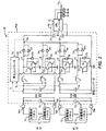
ここで図2を参照すると、例示的な昇圧コンバータ20のハイレベル回路図が図示されている。この具体的な昇圧コンバータの構成は一例として与えられているが、本開示の概念は、当業者には既知の任意の数の昇圧コンバータ構成にも等しく適用されることになる。図示された昇圧コンバータ20は、4チャネルのインターリーブされた昇圧コンバータ構成を有している。各チャンネルは文字Aから文字Dを用いて指定されており、DC−DC変換を提供するのに十分な回路を搭載している。
Referring now to FIG. 2, a high level circuit diagram of an
チャンネルA,Bは列S1からのDC出力を処理するように配置され、また、チャンネルC,Dは列S2からのDC出力を処理するように配置されている。具体的には、列S1の太陽電池パネル12は、端子TM1と端子TM2との間で結合されており、端子TM1と端子TM2とは、コモンモードチョークCH1の向かい合うコイルの入力にそれぞれ結合されている。大容量キャパシタC1が端子TM1と端子TM2との間に結合されてもよい。コモンモードチョークCH1の上側のコイルの出力はチャネルA,Bの入力となる。大容量キャパシタC2がチャネルA,Bの入力とグラウンドとの間に結合されている。コモンモードチョークCH1の下側のコイルの出力がグラウンドに接続されている。
Channels A and B are arranged to process the DC output from column S1, and channels C and D are arranged to process the DC output from column S2. Specifically, the
チャネルAは、ノードN0で終端し、直列経路に沿って直列インダクタL1と1対の並列ダイオードD1,D2とを含んでいる。ダイオードD1,D2のアノードはインダクタL1に結合され、カソードは出力ノードN0に結合されている。主経路に沿った、インダクタL1とダイオードD1,D2との間にある点には、グラウンドへのシャント回路が設けられている。シャント回路は、1対の並列トランジスタT1,T2と少なくとも1つの逆並列ダイオードD3とを含む。ダイオードD3は、トランジスタT1,T2内に組み込まれるボディダイオードを表してもよく、または、追加のダイオードであってもよい。したがって、トランジスタT1,T2のゲート、ドレイン、及びソースはそれぞれ、互いに直接結合されている。ダイオードD3は、トランジスタT1,T2のドレインとソースとの間に逆並列で結合されている。本実施形態では、シャント回路は、一次側スイッチング回路とみなされている。コンバータのための一次側スイッチング回路は、最大電流及び/または最大電圧を切り換えるトランジスタを含むことになる。 Channel A terminates at node N0 and includes a series inductor L1 and a pair of parallel diodes D1, D2 along a series path. Diodes D1, D2 have their anodes coupled to inductor L1 and their cathodes coupled to output node N0. A shunt circuit to the ground is provided at a point along the main path between the inductor L1 and the diodes D1 and D2. The shunt circuit includes a pair of parallel transistors T1, T2 and at least one antiparallel diode D3. The diode D3 may represent a body diode incorporated in the transistors T1, T2, or may be an additional diode. Thus, the gates, drains, and sources of transistors T1, T2 are each directly coupled to each other. Diode D3 is coupled in antiparallel between the drain and source of transistors T1, T2. In the present embodiment, the shunt circuit is regarded as a primary side switching circuit. The primary side switching circuit for the converter will include a transistor that switches the maximum current and / or maximum voltage.
上述したように、チャネルAとチャネルBとは同じ入力を共有している。チャネルAと同様に、チャネルBは、ノードN0で終端し、直列インダクタL2と1対の並列ダイオードD4,D5とを含んでいる。インダクタL2とダイオードD4,D5との間にある点には、グラウンドへのシャント回路が設けられている。シャント回路は、1対の並列トランジスタT3,T4と少なくとも1つの逆並列ダイオードD6とを含んでいる。ダイオードD6は、トランジスタT3,T4内に組み込まれているボディダイオードを表してもよく、または、追加のダイオードであってもよい。上記のように、トランジスタT3,T4のゲート、ドレイン、ソースはそれぞれ、互いに直接結合されている。 As described above, channel A and channel B share the same input. Like channel A, channel B terminates at node N0 and includes a series inductor L2 and a pair of parallel diodes D4, D5. A shunt circuit to the ground is provided at a point between the inductor L2 and the diodes D4 and D5. The shunt circuit includes a pair of parallel transistors T3, T4 and at least one antiparallel diode D6. The diode D6 may represent a body diode incorporated in the transistors T3, T4, or may be an additional diode. As described above, the gates, drains, and sources of the transistors T3 and T4 are directly coupled to each other.
チャネルC,Dは、列S2からの出力を処理するように配置されている。列S2の太陽電池パネル12は、端子TM3と端子TM4との間に結合されており、端子TM3と端子TM4とは、コモンモードチョークCH2の向かい合うコイルの入力にそれぞれ結合されている。大容量キャパシタC3が、端子TM3と端子TM4との間に結合されてもよい。コモンモードチョークCH2の上側のコイルの出力はチャネルC,Dの入力になる。別の大容量キャパシタC4がチャネルC,Dの入力とグラウンドとの間に結合されている。コモンモードチョークCH2の下側のコイルの出力はグラウンドに接続されている。
Channels C and D are arranged to process the output from column S2. The
チャネルA,Bと同様に、チャネルCは、ノードN0で終端し、直列インダクタL3と1対の並列ダイオードD7,D8とを含んでいる。インダクタL3とダイオードD7,D8との間にある点には、グラウンドへのシャント回路が設けられている。シャント回路は、1対の並列トランジスタT5,T6と少なくとも1つの逆並列ダイオードD9とを含んでいる。 Like channels A and B, channel C terminates at node N0 and includes a series inductor L3 and a pair of parallel diodes D7 and D8. A shunt circuit to the ground is provided at a point between the inductor L3 and the diodes D7 and D8. The shunt circuit includes a pair of parallel transistors T5, T6 and at least one antiparallel diode D9.
チャネルA,B,Cと同様に、チャネルDは、ノードN0で終端し、直列インダクタL4と1対の並列ダイオードD10,D11とを含んでいる。インダクタL4とダイオードD10,D11との間にある点には、グラウンドへのシャント回路が設けられている。シャント回路は、1対の並列トランジスタT7,T8と少なくとも1つの逆並列ダイオードD12とを含んでいる。シャント回路のトランジスタT1〜T8は、全体として、昇圧コンバータ20のためのスイッチングトランジスタと称される。ノードN0とグラウンドとの間には1対の直列キャパシタC5,C6が結合されている。ノードN0は、昇圧コンバータ20の出力を表し、よって、DC出力電圧VBはノードN0において供給されている。
Like channels A, B, and C, channel D terminates at node N0 and includes a series inductor L4 and a pair of parallel diodes D10 and D11. A shunt circuit to the ground is provided at a point between the inductor L4 and the diodes D10 and D11. The shunt circuit includes a pair of parallel transistors T7, T8 and at least one antiparallel diode D12. The transistors T1 to T8 of the shunt circuit are generally referred to as switching transistors for the
アナログまたはデジタル昇圧コントローラ26は、昇圧コンバータ20の全体的な昇圧機能を制御している。一般的に、チャネルA,Bは、列S1のDC出力電圧VSを所望のDC出力電圧VBに変換することになる。チャネルC,Dは、列S2のDC出力電圧VSを所望の出力電圧VBに変換することになる。注目に値するのは、全てのチャネルが同時に動作する必要がないのである。例えば、一定の条件の下では、4つのチャネルA〜Dのうちの1つ、2つ、または3つのみが、ある所定の時間において動作する必要がある。動作するチャネルA〜Dの数の決定は、負荷需要、各列S1,S2の出力電力等に依存し得る。
The analog or
さらに、列S1,S2のDC出力電圧VSは、あらゆる所定の時間において異なってもよく、また、時間とともに継続して変動してもよい。したがって、昇圧コントローラ26は、継続的に変動するとともに異なる可能性のある列S1,S2の出力電圧VSを、所望の(そして共通の)出力電圧VBに変換するために、チャネルA〜Dの個々の昇圧機能を動的に制御することになる。本実施形態において、昇圧コントローラ26は、チャネルA,Bの入力における第1入力電流I1と、チャネルC,Dの入力における第2入力電流I2と、DC出力電圧VBとを監視して、チャネルA〜Dの各々に対して個々の昇圧機能をどのように制御するかを決定する。
Furthermore, the DC output voltage V S of the columns S1, S2 may be different at any given time and may vary continuously over time. Thus, the
各チャネルA〜Dは、対応する対の並列トランジスタT1〜T2(チャネルA)、並列トランジスタT3〜T4(チャネルB)、並列トランジスタT5〜T6(チャネルC)、及び並列トランジスタT7〜T8(チャネルD)のゲートを個別の制御信号で駆動することによって、個々に制御される。これらの制御信号は、可変デューティサイクルを有するパルス幅変調(PWM)信号であってもよい。本質的に、各制御信号のデューティサイクルは、対応するチャネルA〜Dの実効電圧利得を制御する。デューティサイクルを増大させると電圧利得も増大し、逆もまた成り立つ。あるチャネルA〜Dの入力電流I1,I2と出力電圧VBとを監視することによって、昇圧コントローラ26は、対応する制御信号のデューティサイクルを調整して、出力電圧VBを確実に所望のレベルに維持できる。
Each channel A-D has a corresponding pair of parallel transistors T1-T2 (channel A), parallel transistors T3-T4 (channel B), parallel transistors T5-T6 (channel C), and parallel transistors T7-T8 (channel D). Are controlled individually by driving individual gates with individual control signals. These control signals may be pulse width modulation (PWM) signals having a variable duty cycle. In essence, the duty cycle of each control signal controls the effective voltage gain of the corresponding channel AD. Increasing the duty cycle also increases the voltage gain and vice versa. By monitoring the input currents I 1 and I 2 and the output voltage V B of certain channels A to D, the
チャネルAの場合、対応する制御信号がトランジスタT1〜T2をオンする状態である場合、インダクタL1を流れる電流は、トランジスタT1〜T2を通ってグラウンドへと導かれる。この位相の間、インダクタL1を流れる電流は、トランジスタT1〜T2がどれだけ長くオン状態であり続けるかに基づいた所望のレベルに向けて増大する。ダイオードD1〜D2は、電流がノードN0からチャネルAに逆流してくるのを阻止することになる。制御信号がトランジスタT1〜T2をオフする状態である場合、インダクタL1を流れる電流は、ダイオードD1,D2を通ってノードN0へと流れざるを得ず、その後、キャパシタC5,C6を充電するか、または3相インバータ22を駆動する。チャネルB〜Dも同様に動作する。
In the case of channel A, when the corresponding control signal turns on the transistors T1 and T2, the current flowing through the inductor L1 is guided to the ground through the transistors T1 and T2. During this phase, the current through inductor L1 increases towards a desired level based on how long transistors T1-T2 remain on. The diodes D1 and D2 prevent the current from flowing back from the node N0 to the channel A. When the control signal is in a state of turning off the transistors T1 to T2, the current flowing through the inductor L1 must flow to the node N0 through the diodes D1 and D2, and then charge the capacitors C5 and C6. Alternatively, the three-
チャネルA〜Dのうちの全て、または複数が動作中の場合、それぞれの制御信号の位相は、スイッチング期間全体を通してオフセットされてもよい。各制御信号が同じ動作周波数を有すると想定すると、各制御信号の位相をオフセットすることによって、ノードN0においてチャネルA〜Dの各々から現れる出力波形がオフセットされる。異なるチャネルA〜Dからの出力波形をオフセットすると、ノードN0において出力電圧VB内に現れているリップルの量が著しく減少する傾向がある。動作中、昇圧コントローラ26は、太陽電池パネル12から最大電力をあらゆる時間における太陽電池パネル12の出力に基づいて収集するために、当業者には既知の技術である最大電力点追尾(MPPT)を実行してもよい。
When all or more of channels A-D are in operation, the phase of each control signal may be offset throughout the switching period. Assuming that each control signal has the same operating frequency, by offsetting the phase of each control signal, the output waveform appearing from each of channels A-D at node N0 is offset. When the output waveforms from the different channels A to D are offset, the amount of ripple appearing in the output voltage V B at the node N0 tends to decrease significantly. During operation, the
一実施形態において、トランジスタT1〜T8及びダイオードD1〜D12は炭化ケイ素パワーデバイスである。トランジスタT1〜T8は、金属膜半導体電界効果トランジスタ(MOSFET)、絶縁ゲート型バイポーラ接合トランジスタ(IGBT)等であってもよい。ダイオードD1〜D12は、シリコンPINダイオードまたはショットキーダイオードであってもよい。 In one embodiment, transistors T1-T8 and diodes D1-D12 are silicon carbide power devices. The transistors T1 to T8 may be metal film semiconductor field effect transistors (MOSFETs), insulated gate bipolar junction transistors (IGBTs), or the like. The diodes D1 to D12 may be silicon PIN diodes or Schottky diodes.
トランジスタT1〜T8及びダイオードD1〜D12に炭化ケイ素を用いることにより、トランジスタは、ソフトスイッチングとは対照的であるハードスイッチングされることが可能であり、シリコン系のシステムよりも大幅に高いスイッチング周波数で動作することができる。ハードスイッチングは、トランジスタが反対の状態からオンまたはオフされる際に、トランジスタ両端の電圧もトランジスタを流れる電流もゼロではない場合に起こる。ソフトスイッチングは、トランジスタが反対の状態からオンまたはオフされる際に、トランジスタ両端の電圧かトランジスタを流れる電流のどちらかが確実にゼロとなるように、一般的に、追加回路と、より複雑なスイッチング制御とを必要とする。したがって、昇圧コントローラ26は、ハードスイッチングが可能である場合にはそのような複雑な制御方式を用いる必要はなく、また、追加のソフトスイッチング回路が必要ないので、電子機器も大幅に簡素化され、占有空間も小さくなり、重量も小さくなる。例示的な炭化ケイ素トランジスタはC2M0080120Dであり、また、例示的な炭化ケイ素ダイオードはC4D10120Dであり、これらはノースカロライナ州ダラムのクリー インコーポレイテッドによって製造されている。
By using silicon carbide for transistors T1-T8 and diodes D1-D12, the transistors can be hard-switched, as opposed to soft-switching, at a significantly higher switching frequency than silicon based systems. Can work. Hard switching occurs when neither the voltage across the transistor nor the current through the transistor is zero when the transistor is turned on or off from the opposite state. Soft switching is generally more complicated with additional circuitry to ensure that either the voltage across the transistor or the current through the transistor is zero when the transistor is turned on or off from the opposite state. Switching control. Therefore, the
シャント回路のトランジスタT1〜T8のスイッチング周波数は、70キロヘルツを超えることが可能であり、通常は70キロヘルツから100キロヘルツの間の範囲内であってもよい。例示的なスイッチング周波数は75キロヘルツである。シリコン系システムは、炭化ケイ素系システムとは対照的に、一般的に25キロヘルツ以下で動作するように制限されている。一般的に、スイッチング周波数が高いほど、変換効率が高くなる。昇圧コンバータ20は、800ボルト、1000ボルト、及びそれ以上において、5キロワット、10キロワット、及び25キロワットを超える出力電力レベルに対して、99%より高い出力効率、そして99.25%もの出力効率を供給し得る。
The switching frequency of the shunt circuit transistors T1-T8 can exceed 70 kilohertz and may typically be in the range between 70 kilohertz and 100 kilohertz. An exemplary switching frequency is 75 kilohertz. Silicon-based systems are generally limited to operate below 25 kilohertz, as opposed to silicon carbide-based systems. Generally, the higher the switching frequency, the higher the conversion efficiency.
注目に値するのは、比較的大きなコモンモードチョークCH1,CH2及びインダクタL1,L2,L3,L4を含む昇圧コンバータ20の回路を、1つのプリント回路基板(PCB)上に設けてもよいことである。この構成(及びプリント回路基板と図示されている電子機器を含むこと)において、昇圧コンバータ20は、1キログラムあたり7キロワットを超え、1キログラムあたり7キロワットから1キログラムあたり21キロワットの範囲で動作可能な電力対重量比を有する。これらのレベルで電力を供給する際には、強制空冷が必要な場合がある。
It is worth noting that the circuit of the
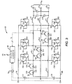
図3を参照して、3相インバータ22の例示的な構成を提供する。多くの様々なタイプのインバータが本明細書に開示された概念を利用し得るが、3レベルTタイプインバータのアーキテクチャが本例では用いられている。一般的に、3相インバータ22は、3つの位相脚PL1,PL2,PL3と、上部線路TRと、下部線路BRとを含んでいる。3つの位相脚PL1,PL2,PL3の回路は同様に作動する。位相脚PL1,PL2,PL3の各々は、昇圧コンバータ20からのDC出力電圧VBを正弦波出力に変換するように機能する。唯一の違いは、3つの位相脚PL1,PL2,PL3の出力O1,O2,O3におけるAC電圧及び電流が、互いに120度位相がずれていることである。最初に、位相脚PL1の回路及び動作を詳細に説明する。
With reference to FIG. 3, an exemplary configuration of a three-
3相インバータ22は、上部線路TRと下部線路BRとの間で結合された2つの直列キャパシタC7,C8を含んでいる。キャパシタC7,C8間に設けられたノードは、中間ノードNを提供する。中間ノードNは、位相脚PL1,PL2,PL3の各々が分岐する共通点に相当する。
Three-
位相脚PL1は、中間ノードNと出力O1との間に直列接続されている、双方向補助スイッチとインダクタL5とを含んでいる。双方向補助スイッチは、2つのトランジスタT9,T10と2つのダイオードD12,D13とを含んでいる。双方向補助スイッチは、以下にさらに詳細に記載される一定の条件下では、電流が、中間ノードNから出力O1へと、トランジスタT9とダイオードD13とを通って流れることができ、かつ、出力O1から中間ノードNへと、トランジスタT10とダイオードD12とを通って流れることができるように構成されている。 Isoashi PL1 are connected in series between the intermediate node N and output O 1, and a bi-directional auxiliary switch and the inductor L5. The bidirectional auxiliary switch includes two transistors T9 and T10 and two diodes D12 and D13. The bi-directional auxiliary switch allows current to flow from the intermediate node N to the output O 1 through the transistor T9 and the diode D13 under certain conditions described in more detail below, and the output From O 1 to the intermediate node N, it can flow through the transistor T10 and the diode D12.
双方向補助スイッチとインダクタL5との間にあるノードは、上部主スイッチを介して上部線路TRに結合され、下部主スイッチを介して下部線路BRに結合されている。上部主スイッチは、2つの並列接続トランジスタT11,T12と、外付けダイオードであってもトランジスタT11,T12のうちの1つのボディダイオードであってもよい、少なくとも1つの逆並列ダイオードD14とを含むスイッチング回路である。同様に、下部主スイッチは、2つの並列接続トランジスタT13,T14と、外付けダイオードであってもトランジスタT13,T14のうちの1つのボディダイオードであってもよい、少なくとも1つの逆並列ダイオードD15とを含んでいる。トランジスタT11,T12のドレイン、ゲート、及びソースはそれぞれ、共に直接結合されている。トランジスタT13,T14のドレイン、ゲート、及びソースは同様の手法で結合されている。本実施形態では、上部主スイッチ及び下部主スイッチはそれぞれ、一次側スイッチング回路とみなされている。インバータの一次側スイッチング回路は、最大電流及び/または最大電圧を切り換えるトランジスタを含むことになる。 A node between the bidirectional auxiliary switch and the inductor L5 is coupled to the upper line TR via the upper main switch and is coupled to the lower line BR via the lower main switch. The upper main switch includes two parallel-connected transistors T11 and T12, and at least one anti-parallel diode D14, which may be an external diode or one of the body diodes of the transistors T11 and T12. Circuit. Similarly, the lower main switch includes two parallel-connected transistors T13 and T14 and at least one anti-parallel diode D15, which may be an external diode or a body diode of the transistors T13 and T14. Is included. The drains, gates, and sources of transistors T11 and T12 are each directly coupled together. The drains, gates, and sources of transistors T13 and T14 are coupled in a similar manner. In this embodiment, each of the upper main switch and the lower main switch is regarded as a primary side switching circuit. The primary side switching circuit of the inverter will include a transistor for switching the maximum current and / or the maximum voltage.
3相インバータ22はまた、インバータコントローラ28を含み、インバータコントローラ28は、アナログでもデジタルであってもよく、また、脚PL1,PL2,PL3の各々の双方向補助スイッチ、上部主スイッチ、及び下部主スイッチに対して、独立した各制御信号CSを供給するように構成されてもよい。位相脚PL1を再度一次基準として、4つの制御信号が使用される。第1制御信号CS1は、上部主スイッチ内の2つのトランジスタT11,T12のゲートに提供され、第2制御信号CS2は、下部主スイッチ内のトランジスタT13,T14のゲートに提供され、第3制御信号CS3は、双方向補助スイッチ内のトランジスタT9のゲートに提供され、第4制御信号CS4は、双方向補助スイッチ内のトランジスタT10のゲートに提供される。
The three-
上述のように、位相脚PL1,PL2,PL3の各々の目的は、DC信号、この場合は昇圧コンバータ20からの出力電圧VBから正弦波AC出力信号を生成することである。位相脚PL1の場合、本質的に3つの動作状態が存在する。第1の状態は、正弦波AC出力信号の正の半サイクルに対応し、第2の状態は、正弦波AC出力信号の負の半サイクルに対応し、第3の状態は、正弦波AC出力信号のゼロクロスに対応する。
As mentioned above, the purpose of each Isoashi PL1, PL2, PL3 is, DC signal, this case is to generate a sine wave AC output signal from the output voltage V B from
正の半サイクルを生成中である第1の状態の間、制御信号CS2,CS4は、下部主スイッチの並列トランジスタT13,T14をオフするとともに、双方向補助スイッチのトランジスタT10をオフするように構成されている。さらに、制御信号CS1,CS3は、上部主スイッチの並列トランジスタT11,T12と双方向補助スイッチのトランジスタT9とを相補的にオン及びオフを切り換えるように構成されている。したがって、双方向補助スイッチとインダクタL5との間にあるノードは、正の半サイクルの間は上部線路TRと中間ノードNとの間で高速にスイッチングされて、インダクタL5を通る正の電流を制御する。一実施形態において、制御信号CS1,CS3は、正の半サイクルの中央よりも正の半サイクルの始まりや終わりにおいてより狭いパルス(より低いデューティサイクル)をもたらす相補的な正弦波PWM信号である。 During the first state in which a positive half cycle is being generated, the control signals CS2, CS4 are configured to turn off the parallel transistors T13, T14 of the lower main switch and turn off the transistor T10 of the bidirectional auxiliary switch. Has been. Further, the control signals CS1 and CS3 are configured to switch on and off complementarily the parallel transistors T11 and T12 of the upper main switch and the transistor T9 of the bidirectional auxiliary switch. Thus, the node between the bi-directional auxiliary switch and the inductor L5 is rapidly switched between the upper line TR and the intermediate node N during the positive half cycle to control the positive current through the inductor L5. To do. In one embodiment, the control signals CS1, CS3 are complementary sinusoidal PWM signals that provide a narrower pulse (lower duty cycle) at the beginning and end of the positive half cycle than at the center of the positive half cycle.
負の半サイクルを生成中である第2の状態の間、制御信号CS1,CS3は、上部主スイッチの並列トランジスタT11,T12をオフするとともに、双方向補助スイッチのトランジスタT9をオフするように構成されている。さらに、制御信号CS2,CS4は、下部主スイッチの並列トランジスタT13,T14と双方向補助スイッチのトランジスタT10とを相補的にオン及びオフを切り換えるように構成されている。したがって、双方向補助スイッチとインダクタL5との間にあるノードは、負の半サイクルの間は下部線路BRと中間ノードNとの間で高速にスイッチングされて、インダクタL5を通る負の電流を制御する。正の半サイクルの場合と同様に、制御信号CS1,CS3もまた、相補的な正弦波PWM信号であってもよい。AC出力信号におけるゼロクロスの周辺(第3の状態)は、上部主スイッチ、下部主スイッチ、及び双方向補助スイッチ内のトランジスタの全てが、それぞれの対応する制御信号CS1〜CS4によってオフされ得る。 During a second state in which a negative half cycle is being generated, the control signals CS1, CS3 are configured to turn off the upper main switch parallel transistors T11, T12 and turn off the bidirectional auxiliary switch transistor T9. Has been. Further, the control signals CS2 and CS4 are configured to switch on and off complementarily the parallel transistors T13 and T14 of the lower main switch and the transistor T10 of the bidirectional auxiliary switch. Thus, the node between the bi-directional auxiliary switch and the inductor L5 is switched at high speed between the lower line BR and the intermediate node N during the negative half cycle to control the negative current through the inductor L5. To do. As in the case of the positive half cycle, the control signals CS1 and CS3 may also be complementary sine wave PWM signals. In the vicinity of the zero cross in the AC output signal (third state), all of the transistors in the upper main switch, the lower main switch, and the bidirectional auxiliary switch can be turned off by their corresponding control signals CS1-CS4.
位相脚PL2,PL3の動作及び構成は、位相脚PL1と同様である。位相脚PL2は、中間ノードNと出力O2との間に直列に接続された、双方向補助スイッチとインダクタL6とを含んでいる。双方向補助スイッチは、2つのトランジスタT15,T16と2つのダイオードD16,D17とを含んでいる。双方向補助スイッチとインダクタL6との間にあるノードは、上部主スイッチを介して上部線路TRに結合され、下部主スイッチを介して下部線路BRに結合されている。 The operations and configurations of the phase legs PL2 and PL3 are the same as those of the phase leg PL1. Isoashi PL2 is connected in series between the intermediate node N and output O 2, and a bi-directional auxiliary switch and the inductor L6. The bidirectional auxiliary switch includes two transistors T15 and T16 and two diodes D16 and D17. A node between the bidirectional auxiliary switch and the inductor L6 is coupled to the upper line TR via the upper main switch and is coupled to the lower line BR via the lower main switch.
上部主スイッチは、2つの並列接続トランジスタT17,T18と、外付けダイオードであってもよいし、または、トランジスタT17,T18のうちの1つのボディダイオードであってもよい、少なくとも1つの逆並列ダイオードD18とを含んでいる。同様に、下部主スイッチは、2つの並列接続トランジスタT19,T20と、外付けダイオードであってもよいし、または、トランジスタT19,T20のうちの1つのボディダイオードであってもよい、少なくとも1つの逆並列ダイオードD19とを含んでいる。トランジスタT17,T18のドレイン、ゲート、及びソースはそれぞれ、共に直接結合されている。トランジスタT19,T20のドレイン、ゲート、及びソースは、同様の手法で結合されている。制御信号の構成に関連する詳細に関しては、位相脚PL1に関する説明を参照されたい。 The upper main switch may be two parallel-connected transistors T17, T18 and an external diode, or at least one anti-parallel diode, which may be a body diode of one of the transistors T17, T18. D18. Similarly, the lower main switch may be two parallel-connected transistors T19, T20 and an external diode, or at least one body diode of one of the transistors T19, T20. And an anti-parallel diode D19. The drains, gates, and sources of transistors T17, T18 are each directly coupled together. The drains, gates, and sources of transistors T19, T20 are coupled in a similar manner. For details relating to the configuration of the control signal, refer to the description relating to the phase leg PL1.
位相脚PL3もまた、中間ノードNと出力O3との間に直列接続された、双方向補助スイッチとインダクタL7とを含んでいる。双方向補助スイッチは、2つのトランジスタT21,T22と2つのダイオードD20,D21とを含んでいる。双方向補助スイッチとインダクタL7との間にあるノードは、上部主スイッチを介して上部線路TRに結合され、下部主スイッチを介して下部線路BRに結合されている。 Isoashi PL3 also connected in series between the intermediate node N and output O 3, and a bi-directional auxiliary switch and inductor L7. The bidirectional auxiliary switch includes two transistors T21 and T22 and two diodes D20 and D21. A node between the bidirectional auxiliary switch and the inductor L7 is coupled to the upper line TR via the upper main switch and is coupled to the lower line BR via the lower main switch.
上部主スイッチは、2つの並列接続トランジスタT23,T24と、外付けダイオードであってもよいし、あるいは、トランジスタT23,T24のうちの1つのボディダイオードであってもよい、少なくとも1つの逆並列ダイオードD22とを含んでいる。同様に、下部主スイッチは、2つの並列接続トランジスタT25,T26と、外付けダイオードであってもよいし、あるいは、トランジスタT25,T26のうちの1つのボディダイオードであってもよい、少なくとも1つの逆並列ダイオードD23とを含んでいる。トランジスタT23,T24のドレイン、ゲート、及びソースはそれぞれ、共に直接結合されている。トランジスタT25,T26のドレイン、ゲート、及びソースは、同様の手法で結合されている。制御信号の構成に関連する詳細に関しては、位相脚PL1に関する説明を参照されたい。なお、キャパシタC9,C10,C11は、それぞれの出力O1,O2,O3の間に結合されている。 The upper main switch may be two parallel-connected transistors T23 and T24 and an external diode, or at least one anti-parallel diode that may be a body diode of one of the transistors T23 and T24. D22. Similarly, the lower main switch may be two parallel-connected transistors T25 and T26 and an external diode, or may be a body diode of one of the transistors T25 and T26. And an anti-parallel diode D23. The drains, gates, and sources of transistors T23 and T24 are each directly coupled together. The drains, gates, and sources of transistors T25 and T26 are coupled in a similar manner. For details relating to the configuration of the control signal, refer to the description relating to the phase leg PL1. Capacitors C9, C10 and C11 are coupled between their respective outputs O 1 , O 2 and O 3 .
出力O1,O2,O3で供給された3つの正弦波AC出力信号において、適切な位相、周波数、及び振幅を維持するために、インバータコントローラ28は、昇圧コンバータ20からのDC出力電圧VBに加えて、様々な位相脚PL1,PL2,PL3の出力電流IOを監視してもよく、それらに基づいて様々な制御信号CSを生成してもよい。当業者であれば、代替のインバータ構成が利用可能であり、これらの構成に本開示の概念が適用可能であることを理解するであろう。さらに、当業者であれば、所望のAC出力信号を生成する代替の制御方式を認識するであろう。
In order to maintain the proper phase, frequency, and amplitude in the three sinusoidal AC output signals provided at outputs O 1 , O 2 , and O 3 ,
昇圧コンバータ20の場合と同様に、3相インバータ22のトランジスタT9〜T26及びダイオードD12〜D23は、炭化ケイ素パワーデバイスであってもよい。トランジスタT9〜T26は、MOSFETやIGBT等であってもよい。ダイオードD12〜D23は、シリコンPINダイオードまたはショットキーダイオードであってもよい。例示的な炭化ケイ素トランジスタは、C2M0080120Dであり、例示的な炭化ケイ素ダイオードは、C4D10120Dであり、これらは、ノースカロライナ州ダラムのクリー インコーポレイテッドによって製造されている。
As in the case of
トランジスタT9〜T26及びダイオードD12〜D23に炭化ケイ素を用いることにより、トランジスタは、ソフトスイッチングとは対照的であるハードスイッチングをされることが可能であり、シリコン系のシステムと比べて大幅に高いスイッチング周波数で動作することができる。したがって、インバータコントローラ28は、ハードスイッチングが可能である場合にはそのような複雑な制御方式を用いる必要はなく、また、追加のソフトスイッチング回路が必要ないので、電子機器も大幅に簡素化され、占有空間も小さくなり、重量も小さくなる。シャント回路のトランジスタT9〜T26のスイッチング周波数は、35キロヘルツを超えることが可能であり、通常は35キロヘルツから60キロヘルツの間の範囲内であってもよい。例示的なスイッチング周波数は、35キロヘルツである。さらに、ハウジング24と、ハウジング24内の電子機器のすべてとを含むインバータシステム14全体は、空冷システムに対して、重量と、1キロワット/キログラムを超える出力電力対重量比とを有してもよい。一実施形態において、インバータシステム14は、約1キロワット/キログラムから3キロワット/キログラムの間の出力電力対重量比を達成可能である。
By using silicon carbide for the transistors T9 to T26 and the diodes D12 to D23, the transistor can be hard switched as opposed to soft switching, which is significantly higher switching than silicon based systems. Can operate at frequency. Therefore, the
当業者であれば、本開示の好適な実施形態の改良や変更を認識するであろう。このような改良や変更はすべて、本明細書に開示された概念及び以下に続く請求項の範囲内であるとみなされる。 Those skilled in the art will recognize improvements and modifications to the preferred embodiments of the present disclosure. All such improvements and modifications are considered within the scope of the concepts disclosed herein and the claims that follow.
Claims (29)
第1DC信号を第2DC信号に変換するように構成されていて、変換処理中にハードスイッチングされる炭化ケイ素トランジスタを有する第1の一次側スイッチング回路を備えている、DC−DC変換回路と、
前記第2DC信号を正弦波AC信号に変換するように構成されていて、前記変換処理中にハードスイッチングされる炭化ケイ素トランジスタを有する第2の一次側スイッチング回路を備えている、インバータと
を備えている、電力変換装置。 A housing;
A DC-DC converter circuit configured to convert a first DC signal into a second DC signal, the DC-DC converter circuit comprising a first primary-side switching circuit having a silicon carbide transistor hard-switched during the conversion process;
An inverter configured to convert the second DC signal to a sinusoidal AC signal and comprising a second primary switching circuit having a silicon carbide transistor that is hard-switched during the conversion process. The power converter.
前記電力変換装置は、重量と、1キロワット/キログラムを超えることが可能な出力電力対重量比とを有している、電力変換装置。 The power conversion device according to claim 1,
The power conversion device has a weight and an output power to weight ratio that can exceed 1 kilowatt / kilogram.
前記電力変換装置は、重量と、約1キロワット/キログラムから3キロワット/キログラムの間を達成可能な出力電力対重量比とを有している、電力変換装置。 The power conversion device according to claim 1,
The power converter has a weight and an output power to weight ratio that can be achieved between about 1 kilowatt / kilogram and 3 kilowatt / kilogram.
前記第1及び第2の一次側スイッチング回路の双方の前記炭化ケイ素トランジスタのうちの前記少なくとも2つは、互いに対して並列に、直接結合されている、電力変換装置。 The power conversion device according to claim 1,
The power conversion device, wherein the at least two of the silicon carbide transistors of both the first and second primary side switching circuits are directly coupled in parallel to each other.
前記第1の一次側スイッチング回路は、少なくとも1つの主信号経路を備え、前記少なくとも1つの主信号経路は、前記少なくとも1つの主信号経路において直列に配置されている1対の並列な炭化ケイ素ダイオードを含んでいる、電力変換装置。 The power conversion device according to claim 4,
The first primary-side switching circuit includes at least one main signal path, and the at least one main signal path is a pair of parallel silicon carbide diodes arranged in series in the at least one main signal path Including a power converter.
DC−DC変換中に、前記第1の一次側スイッチング回路の前記炭化ケイ素トランジスタを、70キロヘルツから100キロヘルツの間の周波数でオン状態とオフ状態との間でスイッチングを行うように構成されているコントローラを備えている、電力変換装置。 The power conversion device according to claim 1, further comprising:
During DC-DC conversion, the silicon carbide transistor of the first primary side switching circuit is configured to switch between an on state and an off state at a frequency between 70 kilohertz and 100 kilohertz. A power conversion device including a controller.
AC−DC変換中、前記第2の一次側スイッチング回路の前記炭化ケイ素トランジスタを、35キロヘルツから60キロヘルツの間の周波数でオン状態とオフ状態との間でスイッチングするように構成されているコントローラをさらに備えている、電力変換装置。 The power conversion device according to claim 1,
A controller configured to switch the silicon carbide transistor of the second primary side switching circuit between an on state and an off state at a frequency between 35 kilohertz and 60 kilohertz during an AC-DC conversion; A power conversion device further provided.
第1コントローラと第2コントローラとを備え、
前記電力変換装置は、重量と、約1キロワット/キログラムから3キロワット/キログラムの間を達成可能な出力電力対重量比とを有し、
前記第1の一次側スイッチング回路及び前記第2の一次側スイッチング回路の双方の前記炭化ケイ素トランジスタのうちの前記少なくとも2つは、互いに並列に直接結合され、
前記第1の一次側スイッチング回路は、少なくとも1つの主信号経路を備え、前記少なくとも1つの主信号経路は、前記少なくとも1つの主信号経路において直列に配置されている1対の並列な炭化ケイ素ダイオードを含み、
前記第1コントローラは、DC−DC変換中に、前記第1の一次側スイッチング回路の前記炭化ケイ素トランジスタを、70キロヘルツから100キロヘルツの間の周波数でオン状態とオフ状態との間でスイッチングするように構成され、
前記第2コントローラは、AC−DC変換中に、前記第2の一次側スイッチング回路の前記炭化ケイ素トランジスタを、35キロヘルツから60キロヘルツの間の周波数でオン状態とオフ状態との間でスイッチングするように構成されている、電力変換装置。 The power conversion device according to claim 1, further comprising:
A first controller and a second controller;
The power converter has a weight and an output power to weight ratio that can achieve between about 1 kilowatt / kilogram to 3 kilowatt / kilogram;
The at least two of the silicon carbide transistors of both the first primary side switching circuit and the second primary side switching circuit are directly coupled in parallel with each other;
The first primary-side switching circuit includes at least one main signal path, and the at least one main signal path is a pair of parallel silicon carbide diodes arranged in series in the at least one main signal path Including
The first controller is configured to switch the silicon carbide transistor of the first primary side switching circuit between an on state and an off state at a frequency between 70 kilohertz and 100 kilohertz during DC-DC conversion. Composed of
The second controller is configured to switch the silicon carbide transistor of the second primary side switching circuit between an on state and an off state at a frequency between 35 kilohertz and 60 kilohertz during AC-DC conversion. It is comprised in the power converter device.
前記少なくとも1つの直列経路の各々に対する、シャント回路であって、前記少なくとも1つの直列経路上の点とグラウンドとの間に結合されており、互いに対して並列に、直接結合されている少なくとも2つの炭化ケイ素トランジスタを備えている、シャント回路と、
前記シャント回路をオン状態とオフ状態との間でスイッチングすることにより、前記入力と前記出力との間でDC−DC変換をもたらすように構成されたコントローラであって、前記DC−DC変換中に、前記少なくとも2つの炭化ケイ素トランジスタがオン状態とオフ状態との間でハードスイッチングされる、コントローラと
を備えている、昇圧コンバータ。 At least one series path coupled between the input and output and comprising an energy storage device and at least one series connected silicon carbide diode;
A shunt circuit for each of the at least one series path, the shunt circuit being coupled between a point on the at least one series path and ground, and in parallel with each other in parallel. A shunt circuit comprising a silicon carbide transistor;
A controller configured to provide a DC-DC conversion between the input and the output by switching the shunt circuit between an on state and an off state, wherein the shunt circuit during the DC-DC conversion And a controller in which the at least two silicon carbide transistors are hard-switched between an on state and an off state.
前記少なくとも1つの直列接続された炭化ケイ素ダイオードは、互いに並列に、直接結合されている少なくとも2つの炭化ケイ素ダイオードを備えている、昇圧コンバータ。 The boost converter according to claim 9, wherein
The boost converter, wherein the at least one series-connected silicon carbide diode comprises at least two silicon carbide diodes directly coupled in parallel with each other.
前記コントローラは、前記シャント回路を、70キロヘルツから100キロヘルツの間の周波数でオン状態とオフ状態との間でスイッチングを行うように構成されている、昇圧コンバータ。 The boost converter according to claim 9, wherein
The boost converter, wherein the controller is configured to switch the shunt circuit between an on state and an off state at a frequency between 70 kilohertz and 100 kilohertz.
前記コントローラは、前記シャント回路を、約75キロヘルツの周波数でオン状態とオフ状態との間でスイッチングを行うように構成されている、昇圧コンバータ。 The boost converter according to claim 9, wherein
The boost converter, wherein the controller is configured to switch the shunt circuit between an on state and an off state at a frequency of about 75 kilohertz.
プリント回路基板を備え、
前記エネルギー貯蔵デバイスは、前記少なくとも1つの直列経路と前記シャント回路とともに前記プリント回路基板上に搭載された直列インダクタであり、
前記昇圧コンバータは、7キロワット/キログラムを超えることが可能な出力電力対重量比を有している、昇圧コンバータ。 The boost converter according to claim 9, further comprising:
With a printed circuit board,
The energy storage device is a series inductor mounted on the printed circuit board along with the at least one series path and the shunt circuit;
The boost converter has an output power to weight ratio that can exceed 7 kilowatts / kilogram.
プリント回路基板を備え、
前記エネルギー貯蔵デバイスは、前記少なくとも1つの直列経路と前記シャント回路とともに前記プリント回路基板上に搭載された直列インダクタであり、
前記昇圧コンバータは、約7キロワット/キログラムから21キロワット/キログラムの間を達成可能な出力電力対重量比を有している、昇圧コンバータ。 The boost converter according to claim 9, further comprising:
With a printed circuit board,
The energy storage device is a series inductor mounted on the printed circuit board along with the at least one series path and the shunt circuit;
The step-up converter has an output power to weight ratio that can achieve between about 7 kilowatts / kilogram to 21 kilowatts / kilogram.
前記少なくとも1つの直列経路は、複数の直列経路を備え、前記複数の直列経路の各々は、前記エネルギー貯蔵デバイスとしての直列インダクタを含み、各シャント回路のスイッチングはインターリーブされる、昇圧コンバータ。 The boost converter according to claim 9, wherein
The boost converter, wherein the at least one series path comprises a plurality of series paths, each of the plurality of series paths including a series inductor as the energy storage device, and the switching of each shunt circuit being interleaved.
前記少なくとも2つの炭化ケイ素トランジスタは、MOSFETである、昇圧コンバータ。 The boost converter according to claim 9, wherein
The boost converter, wherein the at least two silicon carbide transistors are MOSFETs.
プリント回路基板を備え、
前記少なくとも1つの直列接続された炭化ケイ素ダイオードは、互いに並列に、直接結合されている少なくとも2つの炭化ケイ素ダイオードを備え、
前記コントローラは、前記シャント回路を、70キロヘルツから100キロヘルツの間の周波数でオン状態とオフ状態との間でスイッチングするように構成され、
前記エネルギー貯蔵デバイスは、前記少なくとも1つの直列経路と前記シャント回路とともに前記プリント回路基板上に搭載された直列インダクタであり、
前記昇圧コンバータは、約7キロワット/キログラムから21キロワット/キログラムの間を達成可能な出力電力対重量比を有している、昇圧コンバータ。 The boost converter according to claim 9, further comprising:
With a printed circuit board,
The at least one series-connected silicon carbide diode comprises at least two silicon carbide diodes directly coupled in parallel with each other;
The controller is configured to switch the shunt circuit between an on state and an off state at a frequency between 70 kilohertz and 100 kilohertz;
The energy storage device is a series inductor mounted on the printed circuit board along with the at least one series path and the shunt circuit;
The step-up converter has an output power to weight ratio that can achieve between about 7 kilowatts / kilogram to 21 kilowatts / kilogram.
下部線路と、
第1出力に結合されている第1脚と、
前記第1脚と前記上部線路との間に結合された第1上部主スイッチ、及び、前記第1脚と前記下部線路との間に結合された第1下部主スイッチであって、第1上部主スイッチ及び前記第1下部主スイッチはそれぞれ、互いに並列に、直接結合された少なくとも2つの炭化ケイ素トランジスタを備えている、第1上部主スイッチ及び第1下部主スイッチと、
前記第1上部主スイッチと前記第1下部主スイッチとをオン状態とオフ状態との間でスイッチングすることにより、前記上部及び下部線路と前記第1出力との間で第1のAC−DC変換をもたらすように構成されたコントローラであって、前記第1のAC−DC変換中に、前記第1上部及び主スイッチの前記少なくとも2つの炭化ケイ素トランジスタがオン状態とオフ状態との間でハードスイッチングされる、コントローラと
を備えている、インバータ。 The upper track,
The lower track,
A first leg coupled to the first output;
A first upper main switch coupled between the first leg and the upper line; and a first lower main switch coupled between the first leg and the lower line. A first upper main switch and a first lower main switch comprising at least two silicon carbide transistors directly coupled in parallel with each other, the main switch and the first lower main switch;
A first AC-DC conversion between the upper and lower lines and the first output is performed by switching the first upper main switch and the first lower main switch between an on state and an off state. A controller configured to provide a hard switching between an on state and an off state of the at least two silicon carbide transistors of the first upper and main switch during the first AC-DC conversion. And an inverter comprising a controller.
前記第1脚は、1対の直列接続トランジスタと1対の直列接続ダイオードとから形成された双方向補助スイッチを備え、前記直列接続ダイオードの各々は、前記1対の直列接続トランジスタのうちの対応する1つに逆並列に結合されている、インバータ。 The inverter according to claim 18, wherein
The first leg includes a bi-directional auxiliary switch formed by a pair of series connected transistors and a pair of series connected diodes, each of the series connected diodes corresponding to one of the pair of series connected transistors. An inverter that is coupled in antiparallel to one.
前記インバータは、3相インバータであり、
さらに、
第2出力に結合された第2脚と、
前記第2脚と前記上部線路との間に結合された第2上部主スイッチ、及び、前記第2脚と前記下部線路との間に結合された第2下部主スイッチであって、前記第2上部主スイッチ及び前記第2下部主スイッチはそれぞれ、互いに並列に、直接結合された少なくとも2つの炭化ケイ素トランジスタを備えている、第2上部主スイッチ及び第2下部主スイッチと、
第3出力に結合された第3脚と、
前記第3脚と前記上部線路との間に結合された第3上部主スイッチ、及び、前記第3脚と前記下部線路との間に結合された第3下部主スイッチであって、前記第3上部主スイッチ及び前記第3下部主スイッチはそれぞれ、互いに並列に、直接結合された少なくとも2つの炭化ケイ素トランジスタを備えている、第3上部主スイッチ及び第3下部主スイッチと
を備え、
前記コントローラは、さらに、
前記第2上部主スイッチと前記第2下部主スイッチとをオン状態とオフ状態との間でスイッチングすることにより、前記上部及び下部線路と前記第2出力との間で第2のAC−DC変換をもたらすように構成され、前記第2のAC−DC変換中に、前記第2上部及び下部主スイッチの前記少なくとも2つの炭化ケイ素トランジスタがオン状態とオフ状態との間でハードスイッチングされ、そして、
前記第3上部主スイッチと前記第3下部主スイッチとをオン状態とオフ状態との間でスイッチングすることにより、前記上部及び下部線路と前記第2出力との間で第3のAC−DC変換をもたらすように構成され、前記第3のAC−DC変換中に、前記第2上部及び下部主スイッチの前記少なくとも2つの炭化ケイ素トランジスタがオン状態とオフ状態との間でハードスイッチングされ、前記第1、第2、及び第3出力からの正弦波AC出力信号が互いに120度位相がずれている、インバータ。 The inverter according to claim 18, wherein
The inverter is a three-phase inverter;
further,
A second leg coupled to the second output;
A second upper main switch coupled between the second leg and the upper line; and a second lower main switch coupled between the second leg and the lower line. A second upper main switch and a second lower main switch, each of which comprises at least two silicon carbide transistors directly coupled in parallel with each other, the upper main switch and the second lower main switch;
A third leg coupled to the third output;
A third upper main switch coupled between the third leg and the upper line; and a third lower main switch coupled between the third leg and the lower line. The upper main switch and the third lower main switch each comprise a third upper main switch and a third lower main switch comprising at least two silicon carbide transistors directly coupled in parallel with each other,
The controller further includes:
A second AC-DC conversion between the upper and lower lines and the second output by switching the second upper main switch and the second lower main switch between an on state and an off state. And during the second AC-DC conversion, the at least two silicon carbide transistors of the second upper and lower main switches are hard-switched between an on state and an off state; and
A third AC-DC conversion is performed between the upper and lower lines and the second output by switching the third upper main switch and the third lower main switch between an on state and an off state. And during the third AC-DC conversion, the at least two silicon carbide transistors of the second upper and lower main switches are hard-switched between an on state and an off state, An inverter in which the sinusoidal AC output signals from the first, second, and third outputs are 120 degrees out of phase with each other.
前記第1、第2、及び第3脚の各々は、
中間ノードと、前記第1、第2、及び第3出力のうちの対応する1つとの間に延在し、
1対の直列接続トランジスタと1対の直列接続ダイオードとから形成された双方向補助スイッチを備え、
前記直列接続ダイオードの各々は、前記1対の直列接続トランジスタのうちの対応する1つと逆並列に結合されている、インバータ。 The inverter according to claim 20,
Each of the first, second, and third legs is
Extending between an intermediate node and a corresponding one of the first, second and third outputs;
A bidirectional auxiliary switch formed of a pair of series connected transistors and a pair of series connected diodes;
Each of the series connected diodes is coupled in anti-parallel with a corresponding one of the pair of series connected transistors.
前記コントローラは、前記上部及び下部主スイッチを、35キロヘルツから60キロヘルツの間の周波数でオン状態とオフ状態との間でスイッチングするように構成されている、インバータ。 The inverter according to claim 18, wherein
The inverter, wherein the controller is configured to switch the upper and lower main switches between an on state and an off state at a frequency between 35 kilohertz and 60 kilohertz.
前記コントローラは、前記上部及び下部主スイッチを、約50キロヘルツの周波数でオン状態とオフ状態との間でスイッチングするように構成されている、インバータ。 The inverter according to claim 18, wherein
The controller is configured to switch the upper and lower main switches between an on state and an off state at a frequency of about 50 kilohertz.
前記インバータは、Tタイプ3相インバータである、インバータ。 The inverter according to claim 18, wherein
The inverter is a T-type three-phase inverter.
前記電力変換装置は、重量と、1キロワット/キログラムを超えることが可能な出力電力対重量比とを有している、電力変換装置。 A power conversion device comprising a housing and a circuit for converting a first DC signal into a sinusoidal AC signal,
The power conversion device has a weight and an output power to weight ratio that can exceed 1 kilowatt / kilogram.
前記電力変換装置は、重量と、約1キロワット/キログラムから3キロワット/キログラムの間を達成可能な出力電力対重量比とを有している、電力変換装置。 The power conversion device according to claim 25, wherein
The power converter has a weight and an output power to weight ratio that can be achieved between about 1 kilowatt / kilogram and 3 kilowatt / kilogram.
変換処理中にハードスイッチングされる炭化ケイ素トランジスタを有する一次側スイッチング回路を備えている、電力変換装置。 The power conversion device according to claim 26, further comprising:
A power conversion device comprising a primary switching circuit having a silicon carbide transistor that is hard switched during a conversion process.
前記一次側スイッチング回路の前記炭化ケイ素トランジスタのうちの少なくとも2つは、互いに並列に、直接結合されている、電力変換装置。 The power conversion device according to claim 27, wherein
The power conversion device, wherein at least two of the silicon carbide transistors of the primary side switching circuit are directly coupled in parallel with each other.
前記変換処理のうちのDC−DC変換部分中に、前記一次側スイッチング回路の前記炭化ケイ素トランジスタを、70キロヘルツから100キロヘルツの間の周波数でオン状態とオフ状態との間でスイッチングするように構成されたコントローラを備えている、電力変換装置。 The power conversion device according to claim 28, further comprising:
The silicon carbide transistor of the primary side switching circuit is configured to switch between an on state and an off state at a frequency between 70 kilohertz and 100 kilohertz during a DC-DC conversion portion of the conversion process. A power conversion apparatus comprising the controller.
Applications Claiming Priority (3)
| Application Number | Priority Date | Filing Date | Title |
|---|---|---|---|
| US14/193,842 US9680376B2 (en) | 2014-02-28 | 2014-02-28 | Power conversion electronics having conversion and inverter circuitry |
| US14/193,842 | 2014-02-28 | ||
| PCT/US2015/017529 WO2015130787A1 (en) | 2014-02-28 | 2015-02-25 | Power conversion electronics |
Publications (2)
| Publication Number | Publication Date |
|---|---|
| JP2017511103A true JP2017511103A (en) | 2017-04-13 |
| JP2017511103A5 JP2017511103A5 (en) | 2017-07-06 |
Family
ID=52774530
Family Applications (1)
| Application Number | Title | Priority Date | Filing Date |
|---|---|---|---|
| JP2016554411A Pending JP2017511103A (en) | 2014-02-28 | 2015-02-25 | Power conversion electronics |
Country Status (5)
| Country | Link |
|---|---|
| US (1) | US9680376B2 (en) |
| EP (1) | EP3111544B1 (en) |
| JP (1) | JP2017511103A (en) |
| CN (1) | CN106063110B (en) |
| WO (1) | WO2015130787A1 (en) |
Cited By (1)
| Publication number | Priority date | Publication date | Assignee | Title |
|---|---|---|---|---|
| KR20190132091A (en) * | 2018-05-18 | 2019-11-27 | 광운대학교 산학협력단 | Photovoltaic Power Generation Apparatus and Method for MPPT(Maximum Power Point Tracking) |
Families Citing this family (6)
| Publication number | Priority date | Publication date | Assignee | Title |
|---|---|---|---|---|
| US9461547B2 (en) | 2014-03-07 | 2016-10-04 | Cree, Inc. | Converter circuitry |
| US20180187652A1 (en) * | 2017-01-05 | 2018-07-05 | General Electric Company | Power Converter for Full Conversion Wind Turbine Systems |
| US10447085B2 (en) * | 2017-04-10 | 2019-10-15 | Shenzhen Yichong Wireless Power Technology Co. Ltd | Integrated circuit-based wireless charging system and method |
| KR102454222B1 (en) * | 2017-07-21 | 2022-10-17 | 현대자동차주식회사 | Electric vehicle |
| TWI666863B (en) * | 2018-09-07 | 2019-07-21 | 崑山科技大學 | High boost DC converter |
| EP3726719A1 (en) * | 2019-04-15 | 2020-10-21 | Infineon Technologies Austria AG | Power converter and power conversion method |
Citations (6)
| Publication number | Priority date | Publication date | Assignee | Title |
|---|---|---|---|---|
| JPH09215337A (en) * | 1996-01-26 | 1997-08-15 | Bee Shiyuraafuhorusuto & Co | Voltage conversion circuit apparatus for supplying energy to a high output electric load |
| WO2012025978A1 (en) * | 2010-08-23 | 2012-03-01 | 東芝三菱電機産業システム株式会社 | Electricity conversion device |
| JP2013013306A (en) * | 2011-06-29 | 2013-01-17 | General Electric Co <Ge> | Dc to dc power converters and methods of controlling the same |
| WO2013125366A1 (en) * | 2012-02-24 | 2013-08-29 | 三菱電機株式会社 | Power switching circuit |
| JP2013192297A (en) * | 2012-03-12 | 2013-09-26 | Mitsubishi Electric Corp | Power conversion device |
| JP2013219874A (en) * | 2012-04-05 | 2013-10-24 | Hitachi Ltd | Semiconductor drive circuit and power conversion device |
Family Cites Families (18)
| Publication number | Priority date | Publication date | Assignee | Title |
|---|---|---|---|---|
| US5132889A (en) | 1991-05-15 | 1992-07-21 | Ibm Corporation | Resonant-transition DC-to-DC converter |
| US7710081B2 (en) * | 2006-10-27 | 2010-05-04 | Direct Drive Systems, Inc. | Electromechanical energy conversion systems |
| FI119669B (en) * | 2007-06-20 | 2009-01-30 | Vacon Oyj | Voltage pulse limitation |
| US20100301826A1 (en) * | 2009-06-02 | 2010-12-02 | Intersil Americas Inc. | System and method for oring phases to overcome duty cycle limitations in a multi-phase boost converter |
| WO2011111175A1 (en) | 2010-03-09 | 2011-09-15 | 三菱電機株式会社 | Power semiconductor module, power conversion device, and railway vehicles |
| JP5189620B2 (en) * | 2010-06-29 | 2013-04-24 | 三菱電機株式会社 | DC / DC power converter |
| JP5678344B2 (en) | 2010-07-13 | 2015-03-04 | ミネベア株式会社 | Control method of switching power supply |
| CN102064708B (en) | 2010-08-13 | 2014-08-27 | 南京博兰得电子科技有限公司 | Current-input parallel resonance direct-current/ direct-current converter and method |
| US20130063184A1 (en) * | 2010-09-09 | 2013-03-14 | Aegis Technology, Inc | High temperature operation silicon carbide gate driver |
| US20120126728A1 (en) * | 2010-11-19 | 2012-05-24 | El-Refaie Ayman Mohamed Fawzi | Integrated electric machine and silicon carbide power converter assembly and method of making same |
| JP5589096B2 (en) | 2010-12-27 | 2014-09-10 | 日立アプライアンス株式会社 | Power converter and photovoltaic power generation system |
| US9948204B2 (en) | 2011-05-19 | 2018-04-17 | Enphase Energy, Inc. | Method and apparatus for controlling resonant converter output power |
| CN202374014U (en) * | 2011-12-26 | 2012-08-08 | 中科恒源科技股份有限公司 | High frequency link type wind and light complementary control reverse integrated device |
| US9379617B2 (en) | 2012-02-03 | 2016-06-28 | Fuji Electric Co., Ltd. | Resonant DC-DC converter control device |
| US9166472B2 (en) * | 2012-10-11 | 2015-10-20 | Hamilton Sundstrand Corporation | EMI filtering for active rectifier power systems |
| US20150055374A1 (en) | 2013-08-22 | 2015-02-26 | Fujitsu Telecom Networks Limited | Switching power supply apparatus corresponding to zero voltage switching system |
| US9252672B2 (en) | 2013-10-04 | 2016-02-02 | Chicony Power Technology Co., Ltd. | Method of controlling phase-shift full-bridge converter in light load operation |
| US9461547B2 (en) | 2014-03-07 | 2016-10-04 | Cree, Inc. | Converter circuitry |
-
2014
- 2014-02-28 US US14/193,842 patent/US9680376B2/en active Active
-
2015
- 2015-02-25 CN CN201580010730.2A patent/CN106063110B/en active Active
- 2015-02-25 JP JP2016554411A patent/JP2017511103A/en active Pending
- 2015-02-25 WO PCT/US2015/017529 patent/WO2015130787A1/en active Application Filing
- 2015-02-25 EP EP15713043.6A patent/EP3111544B1/en active Active
Patent Citations (6)
| Publication number | Priority date | Publication date | Assignee | Title |
|---|---|---|---|---|
| JPH09215337A (en) * | 1996-01-26 | 1997-08-15 | Bee Shiyuraafuhorusuto & Co | Voltage conversion circuit apparatus for supplying energy to a high output electric load |
| WO2012025978A1 (en) * | 2010-08-23 | 2012-03-01 | 東芝三菱電機産業システム株式会社 | Electricity conversion device |
| JP2013013306A (en) * | 2011-06-29 | 2013-01-17 | General Electric Co <Ge> | Dc to dc power converters and methods of controlling the same |
| WO2013125366A1 (en) * | 2012-02-24 | 2013-08-29 | 三菱電機株式会社 | Power switching circuit |
| JP2013192297A (en) * | 2012-03-12 | 2013-09-26 | Mitsubishi Electric Corp | Power conversion device |
| JP2013219874A (en) * | 2012-04-05 | 2013-10-24 | Hitachi Ltd | Semiconductor drive circuit and power conversion device |
Cited By (2)
| Publication number | Priority date | Publication date | Assignee | Title |
|---|---|---|---|---|
| KR20190132091A (en) * | 2018-05-18 | 2019-11-27 | 광운대학교 산학협력단 | Photovoltaic Power Generation Apparatus and Method for MPPT(Maximum Power Point Tracking) |
| KR102254719B1 (en) * | 2018-05-18 | 2021-05-24 | 광운대학교 산학협력단 | Photovoltaic Power Generation Apparatus and Method for MPPT(Maximum Power Point Tracking) |
Also Published As
| Publication number | Publication date |
|---|---|
| EP3111544A1 (en) | 2017-01-04 |
| EP3111544B1 (en) | 2020-07-08 |
| US9680376B2 (en) | 2017-06-13 |
| CN106063110A (en) | 2016-10-26 |
| US20150249384A1 (en) | 2015-09-03 |
| CN106063110B (en) | 2019-05-14 |
| WO2015130787A1 (en) | 2015-09-03 |
Similar Documents
| Publication | Publication Date | Title |
|---|---|---|
| EP3103189B1 (en) | Multilevel inverter device and operating method | |
| CN108702106B (en) | Low-voltage low-frequency multi-level power converter | |
| JP2017511103A (en) | Power conversion electronics | |
| CN1906837B (en) | DC-DC converter | |
| US9030857B2 (en) | Five-stage neutral point clamped inverter | |
| US8638581B2 (en) | Inverter capable of providing reactive power | |
| EP3105846B1 (en) | Multilevel hybrid inverter and operating method | |
| Khan et al. | Cascaded dual-buck inverter with reduced number of inductors | |
| CN107359855B (en) | Dual-purpose photovoltaic equipment of alternating current-direct current | |
| JP5362657B2 (en) | Power converter | |
| CN100377481C (en) | Integration converton with three phase power factor correction | |
| Roncero-Clemente et al. | Interleaved single-phase quasi-Z-source inverter with special modulation technique | |
| JP5701595B2 (en) | Grid connection device | |
| Ohnuma et al. | A single-phase current source PV inverter with power decoupling capability using an active buffer | |
| Alshammari et al. | A novel synchronous H6 for improving light load efficiency of bidirectional inverters in a DC distribution system | |
| US10812014B1 (en) | Modular photovoltaic string inverter system adapted for SiC MOSFETs | |
| Khodabandeh et al. | A new t-type direct AC/AC converter | |
| Razi et al. | Comparative performance analysis of bipolar and unipolar pseudo-based inverter for off-grid photovoltaic application | |
| Harish et al. | Three phase multi level inverter for high power applications | |
| AU2021107400A4 (en) | Ctu- power electronic inverter system | |
| Sharma et al. | Simulation of a 3-Level Grid Connected Current Mode Level Shifted SPWM Inverter for Renewable Energy Systems | |
| Bhavani et al. | A multi-level single-phase grid connected converter for renewable distributed system | |
| Saxena et al. | A technical review: Single stage and two stage operation for solar system | |
| Ramesh et al. | A cutting-edge single-stage buck-boost transformer-less inverter for 1-φ grid-tied solar PV schemes | |
| KUMAR et al. | Three Phases Nine-Level Grid-Connected Converter Topology for Transformer less PV Systems |
Legal Events
| Date | Code | Title | Description |
|---|---|---|---|
| A521 | Request for written amendment filed |
Free format text: JAPANESE INTERMEDIATE CODE: A523 Effective date: 20170526 |
|
| A621 | Written request for application examination |
Free format text: JAPANESE INTERMEDIATE CODE: A621 Effective date: 20170526 |
|
| A977 | Report on retrieval |
Free format text: JAPANESE INTERMEDIATE CODE: A971007 Effective date: 20180222 |
|
| A131 | Notification of reasons for refusal |
Free format text: JAPANESE INTERMEDIATE CODE: A131 Effective date: 20180320 |
|
| A521 | Request for written amendment filed |
Free format text: JAPANESE INTERMEDIATE CODE: A523 Effective date: 20180620 |
|
| A02 | Decision of refusal |
Free format text: JAPANESE INTERMEDIATE CODE: A02 Effective date: 20180724 |
|
| A521 | Request for written amendment filed |
Free format text: JAPANESE INTERMEDIATE CODE: A523 Effective date: 20181122 |
|
| C60 | Trial request (containing other claim documents, opposition documents) |
Free format text: JAPANESE INTERMEDIATE CODE: C60 Effective date: 20181122 |
|
| A911 | Transfer to examiner for re-examination before appeal (zenchi) |
Free format text: JAPANESE INTERMEDIATE CODE: A911 Effective date: 20181203 |
|
| C21 | Notice of transfer of a case for reconsideration by examiners before appeal proceedings |
Free format text: JAPANESE INTERMEDIATE CODE: C21 Effective date: 20181211 |
|
| A912 | Re-examination (zenchi) completed and case transferred to appeal board |
Free format text: JAPANESE INTERMEDIATE CODE: A912 Effective date: 20190208 |
|
| C211 | Notice of termination of reconsideration by examiners before appeal proceedings |
Free format text: JAPANESE INTERMEDIATE CODE: C211 Effective date: 20190219 |
|
| C22 | Notice of designation (change) of administrative judge |
Free format text: JAPANESE INTERMEDIATE CODE: C22 Effective date: 20190924 |
|
| C30 | Protocol of an oral hearing |
Free format text: JAPANESE INTERMEDIATE CODE: C30 Effective date: 20191129 |
|
| C302 | Record of communication |
Free format text: JAPANESE INTERMEDIATE CODE: C302 Effective date: 20191129 |
|
| C13 | Notice of reasons for refusal |
Free format text: JAPANESE INTERMEDIATE CODE: C13 Effective date: 20191210 |
|
| A601 | Written request for extension of time |
Free format text: JAPANESE INTERMEDIATE CODE: A601 Effective date: 20200306 |
|
| C22 | Notice of designation (change) of administrative judge |
Free format text: JAPANESE INTERMEDIATE CODE: C22 Effective date: 20200407 |
|
| A601 | Written request for extension of time |
Free format text: JAPANESE INTERMEDIATE CODE: A601 Effective date: 20200409 |
|
| A521 | Request for written amendment filed |
Free format text: JAPANESE INTERMEDIATE CODE: A523 Effective date: 20200511 |
|
| C13 | Notice of reasons for refusal |
Free format text: JAPANESE INTERMEDIATE CODE: C13 Effective date: 20200728 |
|
| A601 | Written request for extension of time |
Free format text: JAPANESE INTERMEDIATE CODE: A601 Effective date: 20201016 |
|
| A601 | Written request for extension of time |
Free format text: JAPANESE INTERMEDIATE CODE: A601 Effective date: 20201125 |
|
| A521 | Request for written amendment filed |
Free format text: JAPANESE INTERMEDIATE CODE: A523 Effective date: 20201228 |
|
| C23 | Notice of termination of proceedings |
Free format text: JAPANESE INTERMEDIATE CODE: C23 Effective date: 20210427 |
|
| C03 | Trial/appeal decision taken |
Free format text: JAPANESE INTERMEDIATE CODE: C03 Effective date: 20210601 |
|
| C30A | Notification sent |
Free format text: JAPANESE INTERMEDIATE CODE: C3012 Effective date: 20210601 |