JP2017510941A - Plug-in connector - Google Patents
Plug-in connector Download PDFInfo
- Publication number
- JP2017510941A JP2017510941A JP2016553017A JP2016553017A JP2017510941A JP 2017510941 A JP2017510941 A JP 2017510941A JP 2016553017 A JP2016553017 A JP 2016553017A JP 2016553017 A JP2016553017 A JP 2016553017A JP 2017510941 A JP2017510941 A JP 2017510941A
- Authority
- JP
- Japan
- Prior art keywords
- snap
- plug
- spring contact
- housing
- connector
- Prior art date
- Legal status (The legal status is an assumption and is not a legal conclusion. Google has not performed a legal analysis and makes no representation as to the accuracy of the status listed.)
- Granted
Links
Images

Classifications
-
- H—ELECTRICITY
- H01—ELECTRIC ELEMENTS
- H01R—ELECTRICALLY-CONDUCTIVE CONNECTIONS; STRUCTURAL ASSOCIATIONS OF A PLURALITY OF MUTUALLY-INSULATED ELECTRICAL CONNECTING ELEMENTS; COUPLING DEVICES; CURRENT COLLECTORS
- H01R13/00—Details of coupling devices of the kinds covered by groups H01R12/70 or H01R24/00 - H01R33/00
- H01R13/40—Securing contact members in or to a base or case; Insulating of contact members
- H01R13/42—Securing in a demountable manner
- H01R13/428—Securing in a demountable manner by resilient locking means on the contact members; by locking means on resilient contact members
- H01R13/432—Securing in a demountable manner by resilient locking means on the contact members; by locking means on resilient contact members by stamped-out resilient tongue snapping behind shoulder in base or case
-
- H—ELECTRICITY
- H01—ELECTRIC ELEMENTS
- H01R—ELECTRICALLY-CONDUCTIVE CONNECTIONS; STRUCTURAL ASSOCIATIONS OF A PLURALITY OF MUTUALLY-INSULATED ELECTRICAL CONNECTING ELEMENTS; COUPLING DEVICES; CURRENT COLLECTORS
- H01R13/00—Details of coupling devices of the kinds covered by groups H01R12/70 or H01R24/00 - H01R33/00
- H01R13/02—Contact members
- H01R13/10—Sockets for co-operation with pins or blades
- H01R13/11—Resilient sockets
- H01R13/112—Resilient sockets forked sockets having two legs
-
- H—ELECTRICITY
- H01—ELECTRIC ELEMENTS
- H01R—ELECTRICALLY-CONDUCTIVE CONNECTIONS; STRUCTURAL ASSOCIATIONS OF A PLURALITY OF MUTUALLY-INSULATED ELECTRICAL CONNECTING ELEMENTS; COUPLING DEVICES; CURRENT COLLECTORS
- H01R13/00—Details of coupling devices of the kinds covered by groups H01R12/70 or H01R24/00 - H01R33/00
- H01R13/40—Securing contact members in or to a base or case; Insulating of contact members
- H01R13/42—Securing in a demountable manner
- H01R13/436—Securing a plurality of contact members by one locking piece or operation
- H01R13/4361—Insertion of locking piece perpendicular to direction of contact insertion
-
- H—ELECTRICITY
- H01—ELECTRIC ELEMENTS
- H01R—ELECTRICALLY-CONDUCTIVE CONNECTIONS; STRUCTURAL ASSOCIATIONS OF A PLURALITY OF MUTUALLY-INSULATED ELECTRICAL CONNECTING ELEMENTS; COUPLING DEVICES; CURRENT COLLECTORS
- H01R43/00—Apparatus or processes specially adapted for manufacturing, assembling, maintaining, or repairing of line connectors or current collectors or for joining electric conductors
- H01R43/16—Apparatus or processes specially adapted for manufacturing, assembling, maintaining, or repairing of line connectors or current collectors or for joining electric conductors for manufacturing contact members, e.g. by punching and by bending
Landscapes
- Engineering & Computer Science (AREA)
- Manufacturing & Machinery (AREA)
- Details Of Connecting Devices For Male And Female Coupling (AREA)
- Connector Housings Or Holding Contact Members (AREA)
Abstract
ハウジングと、ハウジング内部のロック要素によって取り付け可能な少なくとも1つの電気的接触要素を受けるための少なくとも1つのチャンバとを備えるプラグインコネクタが記載されている。ロック要素は、接触要素に配置されたロックフックであり、ロックフックは、ロックフックに適合された開口内においてハウジング内部でラッチ可能であり、少なくとも1つの接触要素はバネ接触要素であり、そのバネ接触部は、U字形状に曲げられたシートメタルの複数の脚部として形成されており、スナップイン要素は、U字形状に曲げられたシートメタルの上方において蓋状に、すなわち、スナップイン要素がバネ接触部の前方領域にまで達する様に配置されているという点で特徴付けられている。A plug-in connector is described comprising a housing and at least one chamber for receiving at least one electrical contact element attachable by a locking element inside the housing. The locking element is a locking hook disposed on the contact element, the locking hook being latchable within the housing within an opening adapted to the locking hook, at least one contact element being a spring contact element, the spring The contact portion is formed as a plurality of legs of sheet metal bent into a U-shape, and the snap-in element is in a lid shape above the sheet metal bent into a U-shape, that is, a snap-in element Is characterized in that it is arranged to reach the front region of the spring contact.
Description
本発明は、ハウジングと、ハウジング内部のロック要素によって取り付け可能な少なくとも1つの電気的接触要素を受けるための少なくとも1つのチャンバとを備えるプラグインコネクタに関する。ロック要素は、接触要素に配置されたロックフックであり、当該ロックフックに適合された開口において、ハウジング内部の定位置にロック可能である。 The invention relates to a plug-in connector comprising a housing and at least one chamber for receiving at least one electrical contact element attachable by a locking element inside the housing. The locking element is a locking hook arranged on the contact element and can be locked in place in the housing in an opening adapted to the locking hook.
二次ロックデバイスを備えたプラグインコネクタが、例えば、DE 20 2006 010 308 U1から得られる。プラグインコネクタのベース要素に配置された少なくとも1つの接触要素を有するこのプラグインコネクタ内には、少なくとも1つの二次ロック凹部が設けられている。当該少なくとも1つの二次ロック凹部は、接触要素内部で嵌合方向に対して斜めの方向に配置され、二次ロック要素のロックカムは、当該少なくとも1つの二次ロック凹部と二次ロック要素のロック位置でかみ合う。接触要素はバネ接触要素として具体化される。ハウジング内部での取り付けを容易にすべく、ロックフックが2つのバネ接触部を接続するU字型接続板上に配置されるものとする。ロックフックは、ハウジング内部で、対応するロック開口とかみ合う。このロックフックはU字型接続板から打ち抜かれる。ロックフックは、U字型接続板からバネ状に突出し、そのラッチ状態ではハウジング内部で開口とかみ合う。従って、両バネ接触部及びU字型接続板によって形成されたバネ接触要素をハウジング内部で保持する。そのような取り付けでは、限られた張力しか得られない。その上、そのような取り付けは装着プロセスを複雑なものにする。また、U字型接続板から打ち抜かれたフックとしてロックフックを製造することは、かなりの仕事量を伴う。 A plug-in connector with a secondary locking device is obtained, for example, from DE 20 2006 010 308 U1. In this plug-in connector having at least one contact element arranged on the base element of the plug-in connector, at least one secondary locking recess is provided. The at least one secondary lock recess is disposed in an oblique direction with respect to the fitting direction inside the contact element, and the lock cam of the secondary lock element locks the at least one secondary lock recess and the secondary lock element. Engage in position. The contact element is embodied as a spring contact element. In order to facilitate the mounting inside the housing, the lock hook shall be arranged on the U-shaped connecting plate connecting the two spring contact portions. The lock hook engages with a corresponding lock opening inside the housing. This lock hook is punched out of the U-shaped connecting plate. The lock hook protrudes in a spring shape from the U-shaped connecting plate and engages with the opening inside the housing in the latched state. Therefore, the spring contact element formed by both spring contact portions and the U-shaped connecting plate is held inside the housing. With such an attachment, only a limited tension can be obtained. Moreover, such attachment complicates the mounting process. Moreover, manufacturing a lock hook as a hook punched from a U-shaped connecting plate involves a considerable amount of work.
[発明の利点]
技術水準から知られるプラグインコネクタとは対照的に、本発明に係るプラグインコネクタでは、スナップイン要素は、バネ接触部間のU字型接続板において、両バネ接触部から離れる方向に面している側においては配置されず、むしろ、両バネ接触部の上方に、すなわち、スナップイン要素が、U字形状に曲げられたシートメタルの上方において蓋状に配置される様に配置されている。スナップイン要素はまた、バネ接触部の前方領域にまで達する。そのような構造は、より容易でより速い製造を可能にするのみならず、より大きいサイズのスナップイン要素の設計を可能にする。スナップイン要素は、バネ接触部を超えていわば蓋状に突き出るので、より幅広になるよう設計可能であり、この事実、及びバネ接触部の上方のその配置により、当該スナップイン要素はまた、U字型接続板に配置されたスナップイン要素と比べて、抜去力に対するかなり高い抵抗力を促進する。更なる有利な展開が、従属する下位クレームの主題である。例えば、スナップイン要素はロックフックを有し、ロックフックは、その屈曲領域が、バネ接触部の複数の接触開口に面している側において形成される状態で有するものとする。このようにして、ロックフックは複数の接触開口の領域に配置される。
[Advantages of the Invention]
In contrast to the plug-in connector known from the state of the art, in the plug-in connector according to the invention, the snap-in element faces away from both spring contact parts in the U-shaped connecting plate between the spring contact parts. Rather, it is not arranged on the other side, but rather is arranged so that the snap-in elements are arranged in a lid form above the spring contact parts, ie above the sheet metal bent into a U-shape. . The snap-in element also reaches the front area of the spring contact. Such a structure not only allows easier and faster manufacturing, but also allows the design of larger size snap-in elements. Since the snap-in element protrudes like a lid beyond the spring contact, it can be designed to be wider, and due to this fact and its placement above the spring contact, the snap-in element also Compared with the snap-in elements arranged on the letter-shaped connecting plate, it promotes a considerably higher resistance to withdrawal forces. A further advantageous development is the subject of the subordinate claims. For example, the snap-in element has a lock hook, and the lock hook has a bent region formed on a side of the spring contact portion facing the plurality of contact openings. In this way, the lock hook is arranged in the region of the plurality of contact openings.
屈曲領域はスナップイン要素より幅広であるのが好ましい。これにより、より高い曲げ力及び高い安定性が可能となる。 The bend region is preferably wider than the snap-in element. This allows for higher bending forces and higher stability.
より高い安定性を提供し、長尺フック自体が曲げられる危険性を最小にすべく、更に好ましくは、スナップイン要素は、実質的にその全長にわたって延在するビード(beading)を有するものとする。 More preferably, the snap-in element should have a beading extending substantially the entire length to provide greater stability and minimize the risk of the long hook itself being bent. .
更に、有利には、スナップイン要素に面している側において、複数のバネ接触部は、ロックフックがその非係合状態にあるときのための、斜めに位置付けられた支持面を有するものとする。従って、スナップイン要素は、その目的のために設けられたロック開口にラッチされる時点まで複数のバネ接触部上でいわば支持される。この支持面は、スナップイン要素の曲げ角度を大変有利な方式で制限するので、曲げ過ぎによるスナップイン要素の損傷を回避する。 Furthermore, advantageously, on the side facing the snap-in element, the plurality of spring contacts have diagonally positioned support surfaces for when the locking hook is in its disengaged state. To do. The snap-in element is thus supported on the plurality of spring contacts until it is latched into the lock opening provided for that purpose. This support surface limits the bending angle of the snap-in element in a very advantageous manner, thus avoiding damage to the snap-in element due to overbending.
複数のバネ接触部に面している側において、スナップイン要素自体がナイフブレード接触要素用の支持面を有する。ナイフブレード接触要素とバネ接触要素との嵌合状態では、ロック開口からのロックフックの何れのラッチ解除も回避される。なぜなら、その立方体状の外部形状が、バネ接触要素のU字型断面の開口において形成された状態で、当該支持面がナイフブレード接触要素上で支持されているからである。当該開口部は「蓋」、つまりスナップイン要素によって閉じられる。 On the side facing the spring contacts, the snap-in element itself has a support surface for the knife blade contact element. In the fitted state of the knife blade contact element and the spring contact element, any unlatching of the lock hook from the lock opening is avoided. This is because the support surface is supported on the knife blade contact element in a state where the cubic external shape is formed in the opening of the U-shaped cross section of the spring contact element. The opening is closed by a “lid”, ie a snap-in element.
加えて、そのようなプラグインコネクタはまた、DE 20 2006 010 308 U1に説明されるような二次ロックデバイスを有してよい。複数のバネ接触要素の上方にスナップイン要素を配置することを通して、同時に、そのような二次ロックデバイスは大変有利な方式でロック解除から保護され得る。なぜならスナップイン要素は、同時に、二次ロックデバイスのいかなる作動も回避するからである。 In addition, such plug-in connectors may also have a secondary locking device as described in DE 20 2006 010 308 U1. Through placing the snap-in element above the plurality of spring contact elements, at the same time such a secondary locking device can be protected from unlocking in a very advantageous manner. This is because the snap-in element avoids any actuation of the secondary locking device at the same time.
好ましくは、バネ接触要素及びスナップイン要素は互いに一体的に形成されるものとする。製造の容易さに関しては、バネ接触要素及びスナップイン要素は、単一の打ち抜き部分から形成され、複数回曲げられる。 Preferably, the spring contact element and the snap-in element are integrally formed with each other. For ease of manufacture, the spring contact element and the snap-in element are formed from a single stamped portion and bent multiple times.
本発明の例示的な実施形態が、図面において示され、以下の説明でより詳細に説明される。
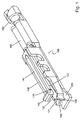
本発明に係るプラグインコネクタのバネ接触要素は、全体として100と称され、図1においてバネ接触部110、120として具体化されている2つの接触要素を備える。これらのバネ接触部110、120は、それ自体が既知である方式でナイフブレード接触要素を受けるよう機能する(図6を参照)。バネ接触部110、120は、接続板130を介して互いに接続される。接続板130と一体となり、2つのバネ接触部110、120はU字形状を取る。このU字型配置は、スナップイン要素140によっていわば蓋状に覆われ、それにより、この蓋と一体となり、当該U字型輪郭は断面でみると矩形輪郭として形成される。
The spring contact element of the plug-in connector according to the present invention is generally referred to as 100, and includes two contact elements embodied as
圧着領域160は、それ自体が既知である方式でリッツ線を受け、圧着するよう機能し、バネ接触部110、120に取り付けられる。圧着領域160には、複数のリッツ線で形成されたケーブルの絶縁クラッドを受ける[よう機能する]歪み解放部162が取り付けられる。
The
スナップイン要素140は、バネ接触部110、120の接触キャップ111、121[から]離れる方向に面している側においてU字型輪郭に取り付けられる。例えば、それはその一体的な部分として形成されてよい。スナップイン要素140は、平坦なメタルシートから打ち抜きプロセスで作製され得る。平坦なメタルシートは3回直角に曲げられる。最初はバネ接触部110、120を形成する目的で、次に、それらのバネ接触部の上方に蓋状に配置されるスナップイン要素140を形成する目的で曲げられる。スナップイン要素140は、長手方向の全体にわたって延在し、延伸したスナップイン要素140の安定性を高める目的を果たすビード141を備える。接触キャップ111、121に面している前端に、ロックフック142がスナップイン要素140において形成される。その機能は、以下でより詳細に説明される。
The snap-in
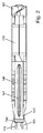
バネ接触部110、120の上側において、すなわち、スナップイン要素140に向かって面している端部において、バネ接触部110、120は、斜めに伸び、スナップイン要素の支持面として形成された表面112、122を有する。図2に具体的に見られるように、図1においてもまた見られるが、スナップイン要素140はロックフック142の領域に屈曲領域143を有する。その屈曲領域143は、スナップイン要素140自体より幅広になるように形成される。これは、ロックフック142の安定性を高める目的を果たし、結果的にまた、プラグインコネクタのハウジングからの抜去力を高める目的を果たす。
On the upper side of the
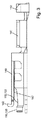
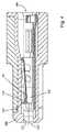
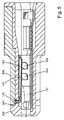
図4から図6は、プラグインコネクタを、より具体的には、ハウジング200内部の上述されたバネ接触要素100の配置を示す。図4は、ラッチの目的で設けられた、ハウジング200の開口240内部にまだラッチされていない状態のスナップイン要素140を示す。図4に見られるように、バネ接触要素100の形態の電気的接触要素は、ハウジング200のチャンバ201に配置される。ハウジング200はプラグ側に開口202を、及びケーブル側に開口204を有する。プラグ側に位置する開口202は、それ自体が既知である方式でナイフブレード接触要素をプラグインするよう機能し、開口204は、ハウジング200からケーブル(図示せず)を導き出すよう機能する。バネ接触要素100は、後側から、すなわち開口204からハウジング200に挿入される。初めは、スナップイン要素140はまだラッチされていない。その代わりに、スナップイン要素140は下方に曲げられ、支持面112、122上で支持されている。スナップイン要素140がその様に支持されることで、スナップイン要素140が曲がる可能性が制限され、それにより、曲げ過ぎによりスナップイン要素140に与えられ得るいかなる損傷もがまた回避される。バネ接触要素100がハウジング200に完全に挿入された後、スナップイン要素140の完全な係合が生じる。この目的のために、ロックフック142は、この目的のために設けられた、ハウジング200の開口240とかみ合う。その状態は図5に示される。
4 to 6 show the plug-in connector, more specifically the arrangement of the
ナイフブレード接触要素500がバネ接触要素100に挿入された後、図6に概略的に示されるように、スナップイン要素140のいかなるラッチ解除も、すなわち、ロックフック142の開口240からのいかなるラッチ解除も有効で安全な方式で回避される。つまり、その場合、スナップイン要素140は、ナイフブレード接触要素500と面しているその支持面147で、ナイフブレード接触要素500上で支持され、それにより、プラグイン状態ではスナップイン要素のいかなるラッチ解除も起きないようにする。図4から図6において更に示されるように、そのようなプラグインコネクタはまた、ロックカム310、320を備える二次ロックデバイス300を有してよい。ロックカム310、320は、対応するバネ接触要素のロック凹部181、182にかみ合う。
After the knife
バネ接触部110、120の上側において、すなわち、スナップイン要素140に向かって面している端部において、バネ接触部110、120は、斜めに伸び、スナップイン要素の支持面として形成された表面112、122を有する。図2または図3に具体的に見られるように、図1においてもまた見られるが、スナップイン要素140はロックフック142の領域に屈曲領域143を有する。その屈曲領域143は、スナップイン要素140自体より幅広になるように形成される。これは、ロックフック142の安定性を高める目的を果たし、結果的にまた、プラグインコネクタのハウジングからの抜去力を高める目的を果たす。
On the upper side of the
Claims (9)
Applications Claiming Priority (3)
| Application Number | Priority Date | Filing Date | Title |
|---|---|---|---|
| DE102014002669.8A DE102014002669B4 (en) | 2014-02-28 | 2014-02-28 | Connectors |
| DE102014002669.8 | 2014-02-28 | ||
| PCT/DE2015/100066 WO2015127926A1 (en) | 2014-02-28 | 2015-02-18 | Plug connector |
Publications (2)
| Publication Number | Publication Date |
|---|---|
| JP2017510941A true JP2017510941A (en) | 2017-04-13 |
| JP6501418B2 JP6501418B2 (en) | 2019-04-17 |
Family
ID=52807471
Family Applications (1)
| Application Number | Title | Priority Date | Filing Date |
|---|---|---|---|
| JP2016553017A Expired - Fee Related JP6501418B2 (en) | 2014-02-28 | 2015-02-18 | Plug-in connector |
Country Status (14)
| Country | Link |
|---|---|
| US (1) | US9722343B2 (en) |
| EP (1) | EP3111518B1 (en) |
| JP (1) | JP6501418B2 (en) |
| KR (1) | KR20160138432A (en) |
| CN (1) | CN106104935B (en) |
| BR (1) | BR112016019760A2 (en) |
| CA (1) | CA2940489A1 (en) |
| DE (1) | DE102014002669B4 (en) |
| DK (1) | DK3111518T3 (en) |
| ES (1) | ES2851424T3 (en) |
| IL (1) | IL247479B (en) |
| MX (1) | MX371260B (en) |
| TW (1) | TWI650907B (en) |
| WO (1) | WO2015127926A1 (en) |
Families Citing this family (3)
| Publication number | Priority date | Publication date | Assignee | Title |
|---|---|---|---|---|
| DE102014002669B4 (en) * | 2014-02-28 | 2019-02-21 | Erni Production Gmbh & Co. Kg | Connectors |
| US10172242B1 (en) * | 2018-01-12 | 2019-01-01 | Xiamen Ghgm Industrial Trade Co., Ltd. | All-metal side-inserted female connector having guide hole and elastic pieces for guiding wire |
| DE102021100806A1 (en) * | 2021-01-15 | 2022-07-21 | Te Connectivity Germany Gmbh | Contact device and method for producing the contact device |
Citations (8)
| Publication number | Priority date | Publication date | Assignee | Title |
|---|---|---|---|---|
| JPS3815878B1 (en) * | 1959-06-04 | 1963-08-26 | ||
| JPS5776379U (en) * | 1980-10-30 | 1982-05-11 | ||
| JPS6273476U (en) * | 1985-10-29 | 1987-05-11 | ||
| JPH0481470U (en) * | 1990-11-28 | 1992-07-15 | ||
| JPH0517951U (en) * | 1991-08-20 | 1993-03-05 | 株式会社カンセイ | Electrical connector |
| JPH09147948A (en) * | 1995-11-14 | 1997-06-06 | Whitaker Corp:The | Electric terminal and electric connector using the same |
| JP2001143807A (en) * | 1999-11-17 | 2001-05-25 | Sumitomo Wiring Syst Ltd | Terminal fitting for waterproof connector |
| JP2013004362A (en) * | 2011-06-17 | 2013-01-07 | Yazaki Corp | Terminal fitting |
Family Cites Families (17)
| Publication number | Priority date | Publication date | Assignee | Title |
|---|---|---|---|---|
| GB1236184A (en) * | 1969-02-27 | 1971-06-23 | Amp Inc | Socket terminals and electrical connectors |
| BE793445A (en) * | 1972-02-08 | 1973-04-16 | Elco Corp | FEMALE PLUG FOR SQUARE SECTION CONTACT PIN |
| US3853389A (en) * | 1972-06-12 | 1974-12-10 | Bunker Ramo | Electrical connector and contact |
| US3932013A (en) * | 1974-04-08 | 1976-01-13 | Amp Incorporated | Shunt assembly |
| US4379611A (en) * | 1980-11-03 | 1983-04-12 | Hughes Aircraft Company | Connector with low force socket contact having an integral hood |
| GB8812881D0 (en) * | 1988-05-31 | 1988-07-06 | Amp Gmbh | Electrical connector |
| DE4402248A1 (en) * | 1994-01-26 | 1995-07-27 | Grote & Hartmann | Contact element and low voltage emitting lamp socket |
| JP3494850B2 (en) * | 1997-06-12 | 2004-02-09 | 矢崎総業株式会社 | Terminal for connector |
| JP3494857B2 (en) * | 1997-08-08 | 2004-02-09 | 矢崎総業株式会社 | Connecting terminal |
| JP3361308B2 (en) * | 1999-12-28 | 2003-01-07 | タイコエレクトロニクスアンプ株式会社 | Female contact and electrical connector using the same |
| JP4278129B2 (en) * | 2002-06-20 | 2009-06-10 | 日本圧着端子製造株式会社 | Socket connector |
| JP2005259602A (en) * | 2004-03-12 | 2005-09-22 | Jst Mfg Co Ltd | connector |
| US7377820B2 (en) | 2004-11-19 | 2008-05-27 | J.S.T. Corporation | Terminal having a protrusion for preventing incorrect insertion |
| DE202006010308U1 (en) | 2006-06-30 | 2006-11-09 | Erni-Elektro-Apparate Gmbh | Plug-in connector for use in motor vehicle industry for creating connection with lambda probe, has secondary interlocking unit with contact unit in which recesses are arranged, and cams that intervene in recesses in interlocking position |
| DE102010024525B4 (en) | 2010-06-21 | 2013-10-24 | Fritz Stepper Gmbh & Co. Kg | Electrical socket contact |
| DE102010034789B3 (en) * | 2010-08-18 | 2011-12-29 | Erni Electronics Gmbh | Connectors |
| DE102014002669B4 (en) * | 2014-02-28 | 2019-02-21 | Erni Production Gmbh & Co. Kg | Connectors |
-
2014
- 2014-02-28 DE DE102014002669.8A patent/DE102014002669B4/en not_active Expired - Fee Related
-
2015
- 2015-02-13 TW TW104105031A patent/TWI650907B/en not_active IP Right Cessation
- 2015-02-18 CN CN201580011161.3A patent/CN106104935B/en not_active Expired - Fee Related
- 2015-02-18 KR KR1020167026777A patent/KR20160138432A/en not_active Ceased
- 2015-02-18 DK DK15713834.8T patent/DK3111518T3/en active
- 2015-02-18 BR BR112016019760-7A patent/BR112016019760A2/en not_active Application Discontinuation
- 2015-02-18 US US15/121,835 patent/US9722343B2/en not_active Expired - Fee Related
- 2015-02-18 JP JP2016553017A patent/JP6501418B2/en not_active Expired - Fee Related
- 2015-02-18 WO PCT/DE2015/100066 patent/WO2015127926A1/en not_active Ceased
- 2015-02-18 EP EP15713834.8A patent/EP3111518B1/en not_active Not-in-force
- 2015-02-18 ES ES15713834T patent/ES2851424T3/en active Active
- 2015-02-18 CA CA2940489A patent/CA2940489A1/en not_active Abandoned
- 2015-02-18 MX MX2016011069A patent/MX371260B/en active IP Right Grant
-
2016
- 2016-08-25 IL IL247479A patent/IL247479B/en active IP Right Grant
Patent Citations (8)
| Publication number | Priority date | Publication date | Assignee | Title |
|---|---|---|---|---|
| JPS3815878B1 (en) * | 1959-06-04 | 1963-08-26 | ||
| JPS5776379U (en) * | 1980-10-30 | 1982-05-11 | ||
| JPS6273476U (en) * | 1985-10-29 | 1987-05-11 | ||
| JPH0481470U (en) * | 1990-11-28 | 1992-07-15 | ||
| JPH0517951U (en) * | 1991-08-20 | 1993-03-05 | 株式会社カンセイ | Electrical connector |
| JPH09147948A (en) * | 1995-11-14 | 1997-06-06 | Whitaker Corp:The | Electric terminal and electric connector using the same |
| JP2001143807A (en) * | 1999-11-17 | 2001-05-25 | Sumitomo Wiring Syst Ltd | Terminal fitting for waterproof connector |
| JP2013004362A (en) * | 2011-06-17 | 2013-01-07 | Yazaki Corp | Terminal fitting |
Also Published As
| Publication number | Publication date |
|---|---|
| TW201547110A (en) | 2015-12-16 |
| DK3111518T3 (en) | 2021-02-01 |
| IL247479B (en) | 2020-05-31 |
| US20170077637A1 (en) | 2017-03-16 |
| MX2016011069A (en) | 2017-01-12 |
| US9722343B2 (en) | 2017-08-01 |
| CA2940489A1 (en) | 2015-09-03 |
| CN106104935B (en) | 2019-05-17 |
| DE102014002669B4 (en) | 2019-02-21 |
| EP3111518B1 (en) | 2020-11-18 |
| EP3111518A1 (en) | 2017-01-04 |
| BR112016019760A2 (en) | 2021-05-25 |
| TWI650907B (en) | 2019-02-11 |
| IL247479A0 (en) | 2016-11-30 |
| ES2851424T3 (en) | 2021-09-07 |
| KR20160138432A (en) | 2016-12-05 |
| MX371260B (en) | 2020-01-23 |
| JP6501418B2 (en) | 2019-04-17 |
| CN106104935A (en) | 2016-11-09 |
| WO2015127926A1 (en) | 2015-09-03 |
| DE102014002669A1 (en) | 2015-09-03 |
Similar Documents
| Publication | Publication Date | Title |
|---|---|---|
| US9039457B2 (en) | Connecting system with locking structure | |
| JP4427564B2 (en) | Connector plug | |
| TWI750343B (en) | Electrical connector | |
| CN105870732A (en) | Holding member, connector connector, and connector | |
| CN104584172A (en) | Electronic component, connection structure of electronic component and terminal fitting, and electrical connection box having electronic component | |
| CN104300268A (en) | Connector | |
| CN111313161B (en) | Connecting terminal | |
| JP6944331B2 (en) | Connector and connector assembly. | |
| CN103855510A (en) | Connector | |
| JP2019016575A5 (en) | ||
| JP6501418B2 (en) | Plug-in connector | |
| JP2019212627A5 (en) | ||
| JP2014220060A (en) | Shield connector | |
| JP2006107820A (en) | Connector | |
| JP5636939B2 (en) | connector | |
| CN105556763A (en) | Connector element | |
| EP3201992B1 (en) | Cooking appliance with terminal box | |
| KR20110024845A (en) | Connector assembly | |
| JP6410166B2 (en) | Connector and connector device | |
| JP5867788B2 (en) | Connector mounting structure | |
| JP6081308B2 (en) | connector | |
| JP6371590B2 (en) | Locking structure between terminal fitting and connector housing | |
| JP2015084311A (en) | Female terminal with outer | |
| JP2016031801A (en) | connector | |
| WO2015099180A1 (en) | Connector |
Legal Events
| Date | Code | Title | Description |
|---|---|---|---|
| A521 | Request for written amendment filed |
Free format text: JAPANESE INTERMEDIATE CODE: A523 Effective date: 20161219 |
|
| A621 | Written request for application examination |
Free format text: JAPANESE INTERMEDIATE CODE: A621 Effective date: 20170911 |
|
| A977 | Report on retrieval |
Free format text: JAPANESE INTERMEDIATE CODE: A971007 Effective date: 20180615 |
|
| A131 | Notification of reasons for refusal |
Free format text: JAPANESE INTERMEDIATE CODE: A131 Effective date: 20180626 |
|
| A521 | Request for written amendment filed |
Free format text: JAPANESE INTERMEDIATE CODE: A523 Effective date: 20180919 |
|
| TRDD | Decision of grant or rejection written | ||
| A01 | Written decision to grant a patent or to grant a registration (utility model) |
Free format text: JAPANESE INTERMEDIATE CODE: A01 Effective date: 20190219 |
|
| A61 | First payment of annual fees (during grant procedure) |
Free format text: JAPANESE INTERMEDIATE CODE: A61 Effective date: 20190318 |
|
| R150 | Certificate of patent or registration of utility model |
Ref document number: 6501418 Country of ref document: JP Free format text: JAPANESE INTERMEDIATE CODE: R150 |
|
| LAPS | Cancellation because of no payment of annual fees |