JP2017510777A - Thermic lance comprising at least four tubular profiles for melt cutting and / or drilling and more than 17 cavities inside the lance - Google Patents
Thermic lance comprising at least four tubular profiles for melt cutting and / or drilling and more than 17 cavities inside the lance Download PDFInfo
- Publication number
- JP2017510777A JP2017510777A JP2016543137A JP2016543137A JP2017510777A JP 2017510777 A JP2017510777 A JP 2017510777A JP 2016543137 A JP2016543137 A JP 2016543137A JP 2016543137 A JP2016543137 A JP 2016543137A JP 2017510777 A JP2017510777 A JP 2017510777A
- Authority
- JP
- Japan
- Prior art keywords
- lance
- thermic
- tubular
- thermic lance
- profile
- Prior art date
- Legal status (The legal status is an assumption and is not a legal conclusion. Google has not performed a legal analysis and makes no representation as to the accuracy of the status listed.)
- Pending
Links
Images


Classifications
-
- C—CHEMISTRY; METALLURGY
- C21—METALLURGY OF IRON
- C21C—PROCESSING OF PIG-IRON, e.g. REFINING, MANUFACTURE OF WROUGHT-IRON OR STEEL; TREATMENT IN MOLTEN STATE OF FERROUS ALLOYS
- C21C5/00—Manufacture of carbon-steel, e.g. plain mild steel, medium carbon steel or cast steel or stainless steel
- C21C5/28—Manufacture of steel in the converter
- C21C5/42—Constructional features of converters
- C21C5/46—Details or accessories
- C21C5/4606—Lances or injectors
- C21C5/4613—Refractory coated lances; Immersion lances
-
- F—MECHANICAL ENGINEERING; LIGHTING; HEATING; WEAPONS; BLASTING
- F27—FURNACES; KILNS; OVENS; RETORTS
- F27D—DETAILS OR ACCESSORIES OF FURNACES, KILNS, OVENS, OR RETORTS, IN SO FAR AS THEY ARE OF KINDS OCCURRING IN MORE THAN ONE KIND OF FURNACE
- F27D3/00—Charging; Discharging; Manipulation of charge
- F27D3/15—Tapping equipment; Equipment for removing or retaining slag
- F27D3/1509—Tapping equipment
- F27D3/1527—Taphole forming equipment, e.g. boring machines, piercing tools
-
- E—FIXED CONSTRUCTIONS
- E21—EARTH DRILLING; MINING
- E21B—EARTH DRILLING, e.g. DEEP DRILLING; OBTAINING OIL, GAS, WATER, SOLUBLE OR MELTABLE MATERIALS OR A SLURRY OF MINERALS FROM WELLS
- E21B7/00—Special methods or apparatus for drilling
- E21B7/14—Drilling by use of heat, e.g. flame drilling
-
- E—FIXED CONSTRUCTIONS
- E21—EARTH DRILLING; MINING
- E21B—EARTH DRILLING, e.g. DEEP DRILLING; OBTAINING OIL, GAS, WATER, SOLUBLE OR MELTABLE MATERIALS OR A SLURRY OF MINERALS FROM WELLS
- E21B7/00—Special methods or apparatus for drilling
- E21B7/14—Drilling by use of heat, e.g. flame drilling
- E21B7/146—Thermal lances
-
- C—CHEMISTRY; METALLURGY
- C21—METALLURGY OF IRON
- C21C—PROCESSING OF PIG-IRON, e.g. REFINING, MANUFACTURE OF WROUGHT-IRON OR STEEL; TREATMENT IN MOLTEN STATE OF FERROUS ALLOYS
- C21C2250/00—Specific additives; Means for adding material different from burners or lances
-
- F—MECHANICAL ENGINEERING; LIGHTING; HEATING; WEAPONS; BLASTING
- F27—FURNACES; KILNS; OVENS; RETORTS
- F27D—DETAILS OR ACCESSORIES OF FURNACES, KILNS, OVENS, OR RETORTS, IN SO FAR AS THEY ARE OF KINDS OCCURRING IN MORE THAN ONE KIND OF FURNACE
- F27D3/00—Charging; Discharging; Manipulation of charge
- F27D3/16—Introducing a fluid jet or current into the charge
- F27D2003/168—Introducing a fluid jet or current into the charge through a lance
- F27D2003/169—Construction of the lance, e.g. lances for injecting particles
Abstract
例えば、粘土(greda)または、アルミナ、シリカ、炭素およびその他の混合物の栓を使用する溶解炉の溶融金属路を穿孔し開口するためなど、任意の種類の材料を溶融によって穿孔および/または切断するため適切な柔軟性および集中した有効発熱能力を有するサーミックランス(1)であって、1本が外部の、および3本が内部の、少なくとも4本の管状形材と前記ランスの内部に収容された17箇所超の空洞とを含み、前記4本の管状形材のうち少なくとも2本は異なる横断面を有し、各管状形材は、前記管状形材の他の管状形材に対して隣接する形で位置し、各管状形材は、横断面が、円形、正方形、三角形、六角形、楕円形、多先端の星形の管状形材から選択されるサーミックランス。さらに、任意の種類の材料を溶融によって切断および/または穿孔するのに有用であるので、サーミックランスの使用について説明する。Perforating and / or cutting any type of material by melting, for example, to drill and open a molten metal path in a melting furnace using a plug of clay or alumina, silica, carbon and other mixtures Therefore, a thermic lance (1) having appropriate flexibility and concentrated effective heat generation capacity, one is external and three is internal, accommodated in at least four tubular profiles and the lance More than 17 cavities, at least two of the four tubular profiles having different cross-sections, each tubular profile being adjacent to other tubular profiles of the tubular profile And each tubular profile is selected from circular, square, triangular, hexagonal, elliptical, multi-tip star-shaped tubular profiles in cross section. Furthermore, the use of a thermic lance will be described as it is useful for cutting and / or drilling any type of material by melting.
Description
本発明は、銅およびスチールなどの鉱物、鉄合金ならびにその他の溶融に利用され、粘土(greda)または、アルミナ、シリカ、炭素およびその他の混合物の栓を使用する溶解炉の溶融金属路を酸化ガス混合物または加圧酸素を使用して穿孔し開口するために利用される、発熱反応による消耗装置に関する。一般的に、本発明の消耗装置は、任意の種類の材料を溶融によって穿孔および/または切断するのに適している。任意の厚さおよび寸法においてである。 The present invention is utilized for the melting of minerals such as copper and steel, iron alloys, and other, oxidizing gas in melting furnaces of melting furnaces using plugs of clay or alumina, silica, carbon and other mixtures. The present invention relates to an exothermic reaction depleting device which is used for drilling and opening using a mixture or pressurized oxygen. In general, the consumable device of the present invention is suitable for drilling and / or cutting any kind of material by melting. At any thickness and dimension.
より具体的には、本発明は、酸素ランスとも呼ばれるサーミックランスに関し、このサーミックランスは、加圧酸素などの酸化ガスを、このサーミックランスの一方の端部から他方の端部へ循環させることを可能にし、バーナーとしても燃焼器としても機能する。 More specifically, the present invention relates to a thermic lance, also called an oxygen lance, which circulates an oxidizing gas such as pressurized oxygen from one end of the thermic lance to the other end. It can function as both a burner and a combustor.
一般的にサーミックランスは長細い管であり、易酸化性の外部本体を有し、その外部本体の全長にソリッドワイヤーなど1つまたは複数の易酸化性の内部部品を含んでいる。内部本体は、外部本体の内部に互いに間隔を置いて配置されている。一般的に、サーミックランスは、直径が8mmから50mm、長さが1mから12mである。 In general, a thermic lance is a long and thin tube having an easily oxidizable outer body, and the entire length of the outer body includes one or more easily oxidizable internal parts such as a solid wire. The inner body is disposed in the outer body at a distance from each other. Generally, the thermic lance has a diameter of 8 mm to 50 mm and a length of 1 m to 12 m.
サーミックランスは、その着火端部で約3,500℃から5,530℃の温度に達し、また酸化ガスの圧力が392.3kPaから980.7kPaの範囲内の場合、1本のサーミックランスの消耗時間は1分当たり約0.2メートルから5メートルとなる。しかし通常は、1本のランスが生成できるエネルギーは、ランス自体の溶融で失われ、例えば鉄の燃焼熱は4.23KJ/gであり、最も一般的なサーミックランス1本を着火させると、一般的には鉄3グラムのうち1グラムが素早く着火するが、他方、他の2グラムは燃焼せずに溶融し、結局、燃焼した1グラムが生成したエネルギーの一部が、燃焼しなかった他の2グラムの溶融に失われることになる。ランス自体においてエネルギーが消耗されると、対象作業に利用できるエネルギーは、それよりもずっと少なくなる。 A thermic lance is depleted of one thermic lance when it reaches a temperature of about 3,500 ° C. to 5,530 ° C. at its ignition end and the pressure of the oxidizing gas is in the range of 392.3 kPa to 980.7 kPa. The time is about 0.2 to 5 meters per minute. However, normally, the energy that one lance can generate is lost due to melting of the lance itself. For example, the heat of combustion of iron is 4.23 KJ / g. When one of the most common thermic lances is ignited, For example, 1 gram of 3 grams of iron ignites quickly, while the other 2 grams melt without burning, and eventually some of the energy produced by 1 gram of burning did not burn. Will be lost to 2 grams of melt. When energy is consumed in the lance itself, much less energy is available for the target task.
発明特許登録第44,086号には、鉱物溶融に利用される溶解炉を穿孔し粘土(greda)製の通路を開口するための装置であって、中空の管状外部本体で形成され、その内部には、外部本体よりも短く、スチールで製造された対称の長手方向本体を備え、該本体は、1つの中心開口部と、好ましくは凸状の少なくとも4つの頂点とを有し、その外部壁は凹状で直線状であり、内部壁は凸状で直線状であり、さらに前記頂点が管状本体の内部壁と接続し、少なくとも4つの空洞が形成され、それらの空洞がシリンダーから供給される酸素の出入りを可能にする装置が記載されている。 The invention patent registration No. 44,086 is an apparatus for drilling a melting furnace used for melting minerals and opening a passage made of clay (greda), formed by a hollow tubular outer body, Comprises a symmetrical longitudinal body, made of steel, shorter than the outer body, the body having one central opening and preferably at least four vertices, the outer wall of which Is concave and straight, the inner wall is convex and straight, and the apex connects with the inner wall of the tubular body to form at least four cavities, which are supplied from the cylinder A device is described that allows the entry and exit of
文献GB1288931には、内部に複数の円筒状ケーブルを含み、隣接する縁にそれらのケーブルが溶接されて管の内部空間全体を占めており、酸化ガス循環用の通路が数カ所しかない金属製管状本体で形成されたサーミックランスが記載されている。 Document GB 1288931 includes a plurality of cylindrical cables inside, and these cables are welded to adjacent edges to occupy the entire interior space of the pipe, and a metal tubular body having only a few passages for oxidizing gas circulation The thermic lance formed in is described.
その一方で文献GB2151530は、アルミニウムもしくは鉄または主に鉄を含有する合金から作られた1本の金属製外部導管、1本の金属製内部導管および/または金属製外部導管内にある多数の金属棒を含み、金属製内部導管および/または金属棒が、アルミニウムもしくは鉄または主にスチールを含有する合金で作られ、少なくとも導管のうち1本または金属棒のうち1本がアルミニウムで作られ、少なくとも導管のうち1本または金属棒のうち1本が鉄または主にスチールを含有する合金で作られたサーミックランスについて説明し、前記ランスは一端に支持部を含み、その支持部には弁が備えられ、使用中にその弁を通って酸素が受け入れられ、他端までランスを貫通して着火することができる。 On the other hand, document GB 2151530 describes a number of metals in one metal outer conduit, one metal inner conduit and / or metal outer conduit made from aluminum or iron or an alloy containing mainly iron. A metal inner conduit and / or metal rod is made of aluminum or iron or an alloy containing mainly steel, at least one of the conduits or one of the metal rods is made of aluminum, A thermic lance is described in which one of the conduits or one of the metal bars is made of iron or an alloy containing mainly steel, the lance including a support at one end, the support having a valve. In use, oxygen can be received through the valve and ignited through the lance to the other end.
文献US4401040には、長手方向軸を有し、両端で開いている、長く伸びた1本のバーナー管と、前記バーナー管の内部に配置された、長く伸びた消耗棒の束とを含み、前記消耗棒が、前記バーナー管に平行かつ共に延びる長手方向軸を有し、前記消耗棒が実質的に同じ横断面の形状を有し、前記消耗棒が配置されることで、少なくとも第1および第2の加圧式燃焼導管と、前記バーナー管の内部表面と前記バーナー管の内部表面に隣接して配置された前記消耗棒の外部表面との間に延びる第1の通路と、前記バーナー管の内部表面に隣接して配置された前記消耗棒の内部表面と前記消耗棒の残部の外部表面との間に延びる第2の通路とを形成する熱トーチが記載されている。 The document U.S. Pat. No. 4,401,040 comprises a long elongated burner tube having a longitudinal axis and open at both ends, and a bundle of elongated elongated consumable rods arranged inside the burner tube, A consumable rod having a longitudinal axis parallel to and extending together with the burner tube, the consumable rod has substantially the same cross-sectional shape, and the consumable rod is disposed so that at least first and first Two pressurized combustion conduits, a first passage extending between an inner surface of the burner tube and an outer surface of the consumable rod disposed adjacent to the inner surface of the burner tube, and the interior of the burner tube A thermal torch is described that forms a second passage extending between an inner surface of the consumable rod disposed adjacent to a surface and an outer surface of the remaining portion of the consumable rod.
文献CH617613は、溶融でき、かつ不規則および規則的な形状を有する粒子を内部に含む中空の管状フレームで形成され、前記粒子が接着剤で固定され、ランスの中核部が酸素透過性である酸素ランスについて説明している。 The document CH617613 is formed of a hollow tubular frame containing particles that can be melted and have irregular and regular shapes therein, the particles are fixed with an adhesive, and the core of the lance is oxygen-permeable oxygen. Explains Lance.
文献GB1317540には、中空の管状本体に内包された複数の円筒形金属ワイヤーを含み、前記管状本体の横断面が縮小して、その内部で前記金属ワイヤーをしっかりと捕らえるサーミックランスが記載されている。 Document GB 1317540 describes a thermic lance comprising a plurality of cylindrical metal wires encased in a hollow tubular body, wherein the tubular body has a reduced cross-section and holds the metal wires firmly inside. .
上記からわかるように、現況技術には様々な種類のサーミックランスが存在している。しかし、より堅牢なものからより柔軟なものまで、要件に応じて、発現する有効発熱能力においても、柔軟性能力においても、より効率的なサーミックランスを利用できることのニーズがなお存在する。さらに、生成されたエネルギーのより高い集中を可能にし、酸化ガス流または酸素流を意のままに操作でき、かつランスの完璧な利用が達成されるランスを利用することのニーズも存在する。 As can be seen from the above, there are various types of thermic lances in the current technology. However, there is still a need to be able to utilize more efficient thermic lances, both in terms of effective heat generation capacity and flexibility capacity, depending on requirements, from more robust to more flexible. In addition, there is a need to utilize a lance that allows a higher concentration of the energy produced, allows the oxidant gas stream or oxygen stream to be manipulated at will, and complete utilization of the lance is achieved.
前記より、本発明の目的は、ランスによって発現する有効発熱能力を増大させ、かつ、エネルギーの集中を達成して、その仕事を管理できるランスを開発することである。 In view of the above, an object of the present invention is to develop a lance that can increase the effective heat generation capacity expressed by the lance, achieve energy concentration, and manage its work.
一方で、本発明の別の目的は、操作時のニーズに従って、様々な酸素流で操作され、均一かつ一定の燃焼を保持できるランスを開発することである。 On the other hand, another object of the present invention is to develop a lance that can be operated with various oxygen flows and maintain a uniform and constant combustion according to the operating needs.
本発明の別の目的は、曲げることができるなど、より高い柔軟性を有するサーミックランスを開発することである。 Another object of the present invention is to develop a thermic lance with higher flexibility, such as being bendable.
本発明のさらに別の目的は、部品を固定および保持するための外部部材を必要としない、つまり連結固定具(ficiones solidares)のみを利用し、内部部材を締めつけることがある溶接、ボルト、くさび、あるいは外部プレスを必要としないサーミックランスを開発することである。 Yet another object of the present invention is to provide welding, bolts, wedges that do not require external members to secure and hold the parts, i.e., use only connection fixtures and may tighten the internal members. Or to develop a thermic lance that does not require an external press.
本発明の別の目的はまた、1,400℃超の高温で溶融せず、それらの温度で燃焼し続けるランスを開発することである。 Another object of the present invention is also to develop a lance that does not melt at high temperatures above 1,400 ° C. and continues to burn at those temperatures.
本発明の別の目的はまた、ランスの使用中にランスの残余の損失を防止するため、別のサーミックランスと容易に連結可能なサーミックランスを提供することである。 Another object of the present invention is also to provide a thermic lance that can be easily coupled to another thermic lance to prevent loss of the lance residual during use of the lance.
本発明は、粘土(greda)または、アルミナ、シリカ、炭素およびその他の混合物の栓を使用する溶解炉の溶融金属路を穿孔し開口するためのサーミックランスであって、ランスの内部に少なくとも4本の管状形材およびランスの内部に収容された17箇所より多くの空洞を含み、管状形材は、横断面が、円形、正方形、三角形、六角形、楕円形、多先端の星形の管状形材から選択されるサーミックランスに関する。 The present invention is a thermic lance for drilling and opening molten metal passages in melting furnaces using plugs of clay or alumina, silica, carbon and other mixtures, with at least four inside the lance. Tube shape and more than 17 cavities housed inside the lance, the tubular shape being circular, square, triangular, hexagonal, elliptical, multi-tip star-shaped tubular shape in cross section It relates to thermic lance selected from materials.
次に本発明を添付の図を参照して説明する。それらの図のうち、
本発明は、例えば、粘土(greda)または、アルミナ、シリカ、炭素およびその他の混合物の栓を使用する溶解炉の溶融金属路を穿孔し開口するためなど、任意の種類の材料を溶融によって穿孔および/または切断するためのサーミックランス(1)であって、1本が外部の、および3本が内部の、少なくとも4本の管状形材と、ランスの内部に収容された17箇所より多くの空洞とを含み、少なくとも4本の管状形材のうち2本は異なる横断面を有し、各管状形材は、前記管状形材の他の管状形材に対して隣接する形で位置し、各管状形材は、横断面が、円形(4)、正方形(6)、三角形(図示せず)、六角形(図示せず)、楕円形(図示せず)、多先端の星形(5)の管状形材から選択されるサーミックランスを説明する。 The present invention perforates and melts any type of material by melting, for example, to drill and open a molten metal path in a melting furnace that uses a plug of clay or alumina, silica, carbon and other mixtures. A thermic lance (1) for cutting, at least four tubular profiles, one external and three internal and more than 17 cavities housed inside the lance Two of the at least four tubular profiles have different cross-sections, each tubular profile positioned adjacent to the other tubular profile of the tubular profile, The tubular section has a cross section of a circle (4), a square (6), a triangle (not shown), a hexagon (not shown), an ellipse (not shown), a multi-tip star (5) A thermic lance selected from the following tubular shapes will be described.
サーミックランスを形成する少なくとも4本の管状形材のうち、1本は外部管状形材であり、その他は内部管状形材であり、外部管状形材は、内部管状形材と、隣接する形材間に形成される空洞とを収容する役割を担う。 Of the at least four tubular shapes forming the thermic lance, one is the outer tubular shape, the other is the inner tubular shape, and the outer tubular shape is the inner tubular shape and the adjacent shape. It plays the role which accommodates the cavity formed between.
本発明の1つの実施形態では、内部形材は、互いに隣に位置し、外部管状形材の内側周囲全体に及ぶ。 In one embodiment of the invention, the inner profiles are located next to each other and span the entire inner perimeter of the outer tubular profile.
本発明の別の実施形態では、内部形材は、互いに、かつ外部管状形材に対して同心的に位置する。この同心実施形態では、ランスを形成する各管状形材は、隣接する形材の横断面とは異なる横断面を有する。 In another embodiment of the invention, the inner profiles are located concentrically with each other and with respect to the outer tubular profile. In this concentric embodiment, each tubular profile forming the lance has a cross section that is different from the cross section of the adjacent profile.
外部管状形材の内部に含まれる空洞は、管状形材の本来の空洞に、隣接する形材の間に形成される空洞を加えた合計に該当する。ランス内に形成されたすべての内部空洞は、様々な幾何形状を有する。各空洞の形状および形材間の空洞の量は、隣接する形材の横断面が有する形状によって異なる。一般的に、4本またはそれ超の多頂点同心形材のランスは、17箇所から100箇所まで、またはそれより多くの内部空洞を発生させる。内部空洞は、サーミックランスの操作中に必要な酸化ガスの自由な循環を可能にし、酸化ガスは、好ましくは酸素流である。内部空洞は、ランスの操作の間、酸化ガス流が適当な乱れをもってランスを貫通することを可能にし、管状形材の壁厚に対するこれらの空洞の寸法の比は、ランスの望まれる効率を達成する比となる。 The cavities contained within the outer tubular profile correspond to the sum of the original cavities of the tubular profile plus the cavities formed between adjacent profiles. All internal cavities formed in the lance have various geometries. The shape of each cavity and the amount of cavities between the profiles depend on the shape of the cross section of the adjacent profile. Generally, four or more multi-vertex concentric lances generate 17 to 100 or more internal cavities. The internal cavity allows for free circulation of the oxidant gas required during the operation of the thermic lance, and the oxidant gas is preferably an oxygen stream. The internal cavities allow the oxidant gas flow to penetrate the lance with proper turbulence during lance operation, and the ratio of the dimensions of these cavities to the wall thickness of the tubular profile achieves the desired efficiency of the lance. It becomes the ratio to do.
内部空洞の形状、大きさおよび量は、ランスがその有効発熱能力をランスの中心部に集中させることを可能にし、それによって同一横断面において、より大きな有効熱エネルギー量の発生が達成され、こうしてランスの効率は2倍になり、現在のランスと比較して同じグラム数のランスより100%多い切断または穿孔を達成し、これは同時に、切断または穿孔時間を少なくとも50%短縮させることを意味する。さらに、ランスは様々な酸化ガス流で、その燃焼を均一かつ一定に保ちながら操作することができ、純度の低い(90%)酸素を使用して、および様々な(高い、および低い)酸素流でも操作することができる。これと異なり、現在のランスは燃焼が集中せず、そうでなければ横断面の様々なポイントで無作為に着火し、さらには長手方向の様々なポイントでも着火するため、現在のランスは、その効率を大幅に低下させ、純度が95%未満の酸素を循環させる場合、および酸素流を過剰に循環させる場合に消火にさえ至ってしまう。 The shape, size and amount of the internal cavity allows the lance to concentrate its effective heat generation capacity in the center of the lance, thereby achieving the generation of a larger amount of effective thermal energy in the same cross section, thus The efficiency of the lance is doubled, achieving 100% more cutting or drilling than the same gram lance compared to the current lance, which at the same time means reducing cutting or drilling time by at least 50% . In addition, the lance can be operated with various oxidizing gas streams, keeping its combustion uniform and constant, using low purity (90%) oxygen, and various (high and low) oxygen flows. But you can operate. Unlike this, the current lance does not concentrate the combustion, otherwise it ignites randomly at various points in the cross section, and even at various points in the longitudinal direction. The efficiency is greatly reduced and even fire extinguishing occurs when circulating oxygen less than 95% in purity and when circulating an oxygen stream excessively.
これに加えて、本発明のランスは、形成された空洞が鉄と酸素流との接触バランスを取ることを可能にするため効率的な燃焼が達成されるので、汚染ガスの放出を減らし、他方、切断または穿孔を行うのに必要とする時間量を少なくし、また酸素流も少なくて済むため、作業コストを低下させる。 In addition to this, the lance of the present invention reduces the emission of pollutant gases, since efficient combustion is achieved because it allows the formed cavities to balance the contact of iron and oxygen flow, while This reduces the amount of time required to perform cutting or drilling and reduces the operating cost because less oxygen flow is required.
各管状形材の厚さは、0.9mm未満から3.0mm超の範囲内に収まる。ある実施形態において、本発明のサーミックランスは、低炭素含有スチールで製造することができる。 The thickness of each tubular profile falls within the range of less than 0.9 mm to more than 3.0 mm. In certain embodiments, the thermic lances of the present invention can be made of low carbon content steel.
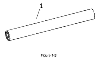
本発明のサーミックランスでは、外部管状形材はランスの覆いを形成し、前記覆いは均一または不規則な外部構造からなる。ランスの外部本体は、その本体全体にわたって横断面が同じであり得るか、または2つ以上の横断面を有し得る。同様に内部形材は、その本体全体にわたって横断面が同じであり得るか、または2つ以上の横断面を有し得る。本発明のサーミックランスは、その外部端が有する形状次第で連結可能であっても(図1−A)、連結不可であってもよい(図1−B)。連結可能なランスとは、外部手段の関与なしで直接、または両方のランスを連結することができる、例えば連結部品または連結装置などの追加手段を介して別のランスと連結できるランスのことである。 In the thermic lance of the invention, the outer tubular profile forms a lance covering, which consists of a uniform or irregular outer structure. The outer body of the lance may have the same cross section throughout the body, or may have more than one cross section. Similarly, the internal profile may have the same cross section throughout its body, or it may have more than one cross section. The thermic lance of the present invention may be connectable (FIG. 1-A) or not connectable (FIG. 1-B) depending on the shape of the outer end thereof. A connectable lance is a lance that can be connected to another lance directly or without the involvement of external means, for example via an additional means such as a connecting part or a connecting device. .
図1−Aには、ランスの覆いの端部が改変され、前記端部が逆円錐(2)の形状を有する、連結可能なサーミックランス(1)の1種が見られる。さらに、均一な覆いの各端部には、逆円錐端の直前に、この種類のランスは平坦かつ円筒形の表面を有し、外部環状溝(3)を備えている。この種類のランスの覆いは、連結不可のランスと同様に、様々な横断面を有することができ、その横断面は外部形材の有する横断面によって異なる。この種類のランスのある実施形態では、均一な覆いは円筒形かつ直線状である。本発明のこの種類のサーミックランスの端部が有する外部形状は、端部の各々においてランスの保持を可能にする中空の外部連結部品または装置を介して一方のランスと他方のランスとの容易な組立てを可能にする。この種類のランスの逆円錐端は、連結部品との嵌合を容易にすることを可能にし、またランスの外部環状溝(3)は、ランスと連結部品との嵌合を確実に行うことを可能にする。この種類のランスは、その2つの端部で連結可能なランスである。この種類のランスの大きさは変えることが可能であり、ランスに与えられる用途によって異なり、またランスの各端部の外部溝の位置は、ランスどうしが連結されている場合にランスが互いに干渉しないことを可能にする。 In FIG. 1-A, one type of connectable thermic lance (1) is seen, in which the end of the lance covering is modified, said end having the shape of an inverted cone (2). Furthermore, at each end of the uniform covering, just before the inverted conical end, this type of lance has a flat and cylindrical surface and is provided with an external annular groove (3). This type of lance covering can have various cross-sections, similar to non-connectable lances, the cross-sections depending on the cross-section of the external profile. In an embodiment with this type of lance, the uniform covering is cylindrical and straight. The external shape of the ends of this type of thermic lance of the present invention facilitates the connection between one lance and the other lance via a hollow external connection piece or device that allows the lance to be held at each of the ends. Allows assembly. The inverted conical end of this type of lance makes it easy to mate with the connecting part, and the outer annular groove (3) of the lance ensures that the lance and the linking part fit together. to enable. This type of lance is a lance that can be connected at its two ends. The size of this type of lance can vary and depends on the application given to the lance, and the position of the external groove at each end of the lance does not interfere with each other when the lances are connected Make it possible.
別の実施形態において、連結可能な本発明のサーミックランスは、その端部の一方のみが逆円錐形であり、これは、その端部の一方のみで連結できることを示している。これに加えて、覆いの前記端部には、逆円錐端の直前に、この種類のランスは平坦かつ円筒形の表面を有し、外部環状溝を備えている。 In another embodiment, the connectable thermic lance of the present invention has only one of its ends being an inverted cone, indicating that it can be connected at only one of its ends. In addition, at the end of the cover, just before the inverted conical end, this type of lance has a flat and cylindrical surface and is provided with an external annular groove.
互いに連結されたランスを利用できることで、その使用時に各ランスの完全な消耗が可能になり、ランスの残余が発生せず、したがって材料の損失がなく、操作がより経済的なものになる。ランスおよび連結部品の端部の形状は、ランスの損失防止を目的として、必要なだけランスを連結することを可能にする。 The availability of lances connected to each other allows complete depletion of each lance during its use, leaving no lance residue, thus eliminating material loss and making operation more economical. The shape of the end of the lance and the connecting part makes it possible to connect the lance as much as necessary for the purpose of preventing loss of the lance.
一般的に、ランスは、その長さを1m未満から10m超の範囲内に収めることができる。 Generally, the lance can have a length within a range of less than 1 m to more than 10 m.
本発明のサーミックランスの別の実施形態では、温度が1,400℃超の場所で作業するランスに適用されるセラミック材料など高融点(2,000℃超)の材料を使用したコーティングが施されており、こうして、ランスが溶融し、その結果としてその形状、酸化ガスを導く能力および燃焼能力を失うのを防止する。ランスのコーティングは、外部形材に、および/または内部形材の少なくとも1本に塗布すればよい。 In another embodiment of the thermic lance of the present invention, a coating is applied using a material with a high melting point (greater than 2,000 ° C.), such as a ceramic material applied to a lance working at a temperature above 1,400 ° C. Thus preventing the lance from melting and consequently losing its shape, ability to direct oxidizing gas and combustion ability. The lance coating may be applied to the outer profile and / or to at least one of the inner profiles.
本発明のサーミックランスは、熱処理工程、機械工程および化学工程を適用することで得られる。各管状形材は、同心的に嵌合される前に、金属成形工程に付され、好ましくは外部環状形材が最初に成形され、内部中心管状形材が最後に成形される。成形工程に付される管状形材の量は、各ランスの設計、つまりランスの特定の設計を達成するのに必要となる形材の量によって異なる。これに加えて、1本のランスを形成する管状形材の量の選択は、ランスに与えられる用途によって異なり、一般的には、直径が2mmのランスから直径が100mmのランスまで持つことができる。 The thermic lance of the present invention can be obtained by applying a heat treatment process, a mechanical process, and a chemical process. Each tubular profile is subjected to a metal forming process before being concentrically fitted, preferably the outer annular profile is molded first and the inner central tubular profile is molded last. The amount of tubular profile that is subjected to the forming process depends on the design of each lance, i.e., the amount of profile required to achieve a particular design of the lance. In addition to this, the choice of the amount of tubular profile forming a single lance depends on the application given to the lance and can generally range from a lance with a diameter of 2 mm to a lance with a diameter of 100 mm. .
ランスの一部を形成する各管状形材の成形工程が終了すると、成形された形材は、熱処理工程、機械工程および化学工程を通じて連結され、それらの工程は組立てを行うほか、形材間の寸法上の干渉を達成し、こうして特定の形材が、その形材に先行する形材に固定(連結)され、こうして形材を、圧力および操作の間にランスを貫通する酸化ガス流または酸素流に耐えるように固定および保持された状態にし、ある形材が別の形材から外れないようにすることが可能になる。 When the forming process of each tubular profile forming a part of the lance is completed, the molded profile is connected through a heat treatment process, a mechanical process, and a chemical process. A dimensional interference is achieved, so that a particular profile is fixed (connected) to the profile that precedes the profile, thus allowing the profile to flow through the oxidant gas or oxygen through the lance during pressure and operation. It is possible to keep it fixed and held to withstand the flow so that one profile does not come off another.
図2は、各形材の横断面の形状および内径において様々な種類の形材を示している。 FIG. 2 shows various types of profiles in terms of the cross-sectional shape and inner diameter of each profile.
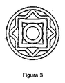
図3は、4本の同心管状形材から形成され、17箇所の内部空洞を有する本発明の1つの実施形態を示している。 FIG. 3 shows one embodiment of the present invention formed from four concentric tubular profiles and having 17 internal cavities.
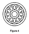
図4は、4本の同心管状形材から形成され、37箇所の内部空洞を有する本発明の1つの実施形態を示している。 FIG. 4 illustrates one embodiment of the present invention formed from four concentric tubular profiles and having 37 internal cavities.
図5は、5本の同心管状形材から形成され、41箇所の内部空洞を有する本発明の1つの実施形態を示している。 FIG. 5 illustrates one embodiment of the present invention formed from five concentric tubular profiles and having 41 internal cavities.
図6および図7は、6本の同心管状形材から形成され、多数の内部空洞を有する本発明の2つの実施形態を示している。 FIGS. 6 and 7 show two embodiments of the present invention formed from six concentric tubular profiles and having multiple internal cavities.
図8および図9はそれぞれ、7本および8本の同心管状形材から形成され、多数の内部空洞を有する本発明の2つの実施形態を示している。 FIGS. 8 and 9 show two embodiments of the invention formed from 7 and 8 concentric tubular profiles, respectively, and having multiple internal cavities.
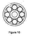
図10は、10本の管状形材から形成され、17箇所の内部空洞を有する本発明の1つの実施形態を示している。 FIG. 10 illustrates one embodiment of the present invention formed from 10 tubular profiles and having 17 internal cavities.
図11は、5本の同心管状形材から形成され、多数の内部空洞を有し、それらの内部空洞が互いに均一および不均一な形状を有する本発明の別の実施形態を示している。 FIG. 11 illustrates another embodiment of the present invention formed from five concentric tubular profiles and having a number of internal cavities, the internal cavities having a uniform and non-uniform shape relative to each other.
驚くことに、ランスを形成する形材の量を変えることが、形材の形状を変えること、およびランス内の形材の一連の順序を変えることと共に、酸化ガス流が通過する上で効率的な空洞の発生を可能にし、これによって形材に含有される鉄の発熱量の利用向上が達成され、さらに、本発明によるランスの形成に使用された形材の横断面が、必要とされるたわみに対する耐久性を意のままに得て、同じ質量の他の種類のランスで得られるよりも大きな耐久性を必要なときに達成できるように設計することを可能にすることが明らかにされた。これに加えて、ランスの一式において得られた幾何形状は、高い精度でランスの作用焦点を集中させ、こうしてより均一でクリーン、正確かつ効率的な切断の達成を可能にする。 Surprisingly, changing the amount of profile forming the lance is efficient in passing the oxidant gas stream, along with changing the profile of the profile, and changing the sequence of profiles within the lance. Cavities can be generated, thereby improving the utilization of the heating value of the iron contained in the profile, and the cross-section of the profile used to form the lance according to the invention is required. It has been shown that it is possible to obtain the durability against deflection at will and to be designed to achieve greater durability when needed than can be obtained with other types of lances of the same mass. . In addition to this, the geometry obtained in the set of lances concentrates the working focus of the lance with high accuracy, thus enabling a more uniform, clean, accurate and efficient cutting to be achieved.
本発明のランスは、ランスの発熱量の利用向上のおかげで、その切断速度および切断能力を増大させ、それによって作業者が高温にさらされる時間の縮小を達成し、熱ストレスのリスクを低下させることを可能にする。 The lance of the present invention, due to the improved utilization of the lance heat generation, increases its cutting speed and cutting capacity, thereby reducing the time that the operator is exposed to high temperatures and reducing the risk of thermal stress. Make it possible.
本発明のランスは、例えば、鍋の底、貯まった銑鉄や付着物、炉ののぞき穴、銅および煉瓦を材料とする炉床、炉壁の付着物、通気管の収納場所の清掃、ガス出口の前室のダクト内の付着物、通路開口部、精練およびアノード炉などの場所で、銅およびスラグを切断する場合など、様々な用途がある。 The lance of the present invention includes, for example, the bottom of a pan, accumulated pig iron and deposits, furnace peepholes, hearths made of copper and brick, furnace wall deposits, cleaning of vent pipe storage, gas outlet There are various applications such as cutting copper and slag at places such as deposits in the ducts of the front chamber, passage openings, scouring and anode furnaces.
サーミックランスは、栓が、たとえ純グラファイト(炭素)製であろうと、それが任意の組成を有することに関係なく、銅、スチール、鉄合金、白金、およびその他の溶解炉の通路を効率的に開口することを可能にする、切断を行うのに利用できる。同じく、任意の品質の、または、例えば1,000mm、2,000mm、3,000mmおよびそれより厚い厚さのスチールを溶融によって切断および/または穿孔するのに使用することができる。同様に、任意の種類および寸法のコンクリートブロックまたは岩および石を切断および/または穿孔するのに使用できる。 Thermic lances efficiently route copper, steel, iron alloys, platinum, and other melting furnace passages, regardless of their composition, whether the plug is made of pure graphite (carbon). Can be used to make a cut that allows opening. Similarly, steel of any quality, for example, 1,000 mm, 2,000 mm, 3,000 mm and thicker can be used to cut and / or perforate by melting. Similarly, it can be used to cut and / or drill any type and size of concrete blocks or rocks and stones.
さらに、すでに述べたように、本発明のサーミックランスは、温度に対する耐久性が最も高いダイヤモンドを含めて、任意の種類の材料を溶融によって切断および/または穿孔するのに使用することができる。
本発明のランスの一般的な使用例は次のとおりである。
Furthermore, as already mentioned, the thermic lances of the present invention can be used to cut and / or drill any type of material, including diamond, which is the most durable to temperature.
A typical use of the lance of the present invention is as follows.
・非鉄材料を効率的かつ正確に切断および/または穿孔するため、高い熱エネルギーを発生させ、同時に酸素流の供給を低くする、またはゼロにする堅牢なランス。 A robust lance that generates high thermal energy and at the same time reduces or eliminates the flow of oxygen to efficiently and accurately cut and / or drill non-ferrous materials.
・鉄材料を効率的かつ正確に切断および/または穿孔するため、低い熱エネルギーを発生させ、同時に酸素流の供給を高くする堅牢なランス。 A robust lance that generates low thermal energy and at the same time provides a high oxygen flow for efficient and accurate cutting and / or drilling of ferrous materials.
・ランスを曲げる必要があるスペースの小さい場所で非鉄材料を切断および/または穿孔するため、高い熱エネルギーを発生させ、同時に酸素流の供給を低くする、またはゼロにする柔軟なランス。 A flexible lance that cuts and / or drills non-ferrous material in small spaces where the lance needs to be bent, thus generating high thermal energy and at the same time lowering or zeroing the oxygen flow.
・ランスを曲げる必要があるスペースの小さい場所で鉄材料を切断および/または穿孔するため、低い熱エネルギーを発生させ、同時に酸素流の供給を高くする柔軟なランス。 A flexible lance that cuts and / or drills ferrous material in a small space where the lance needs to be bent, thus generating low thermal energy and at the same time increasing the supply of oxygen flow.
Claims (22)
Applications Claiming Priority (3)
| Application Number | Priority Date | Filing Date | Title |
|---|---|---|---|
| CL2014000034A CL2014000034A1 (en) | 2014-01-07 | 2014-01-07 | Thermal lance for drilling and / or fusion cutting any material, comprises at least 4 tubular profiles, one outer and three inner, and more than 17 cavities inside the lance, at least 2 of the 4 tubular profiles have different cross sections and the profiles are located contiguously; and use of the spear. |
| CL34-2014 | 2014-01-07 | ||
| PCT/CL2014/000082 WO2015103715A1 (en) | 2014-01-07 | 2014-12-19 | Thermal lance for fusion cutting and/or piercing, comprising at least four tubular profiles and more than 17 cavities inside the lance |
Publications (2)
| Publication Number | Publication Date |
|---|---|
| JP2017510777A true JP2017510777A (en) | 2017-04-13 |
| JP2017510777A5 JP2017510777A5 (en) | 2018-02-01 |
Family
ID=52002244
Family Applications (1)
| Application Number | Title | Priority Date | Filing Date |
|---|---|---|---|
| JP2016543137A Pending JP2017510777A (en) | 2014-01-07 | 2014-12-19 | Thermic lance comprising at least four tubular profiles for melt cutting and / or drilling and more than 17 cavities inside the lance |
Country Status (15)
| Country | Link |
|---|---|
| US (1) | US10048007B2 (en) |
| EP (1) | EP3093426B1 (en) |
| JP (1) | JP2017510777A (en) |
| KR (1) | KR102325559B1 (en) |
| CN (1) | CN105849352B (en) |
| AU (1) | AU2014377303B2 (en) |
| CA (1) | CA2935249C (en) |
| CL (1) | CL2014000034A1 (en) |
| ES (1) | ES2696452T3 (en) |
| MX (1) | MX370353B (en) |
| PE (1) | PE20161157A1 (en) |
| PL (1) | PL3093426T3 (en) |
| RU (1) | RU2692140C2 (en) |
| WO (1) | WO2015103715A1 (en) |
| ZA (1) | ZA201604408B (en) |
Families Citing this family (5)
| Publication number | Priority date | Publication date | Assignee | Title |
|---|---|---|---|---|
| CL2014000034A1 (en) * | 2014-01-07 | 2014-10-03 | Trefimet S A | Thermal lance for drilling and / or fusion cutting any material, comprises at least 4 tubular profiles, one outer and three inner, and more than 17 cavities inside the lance, at least 2 of the 4 tubular profiles have different cross sections and the profiles are located contiguously; and use of the spear. |
| GB201701224D0 (en) * | 2017-01-25 | 2017-03-08 | Cardno Bruce | Downhole operations and associated apparatus |
| CL2017000419A1 (en) * | 2017-02-21 | 2017-12-15 | Trefimet S A | Lanza termica consumible por reaccion exotermica que es utilizada para perforar y/o cortar cualquier tipo de material de diferentes espesores y dimensiones, posee un cuerpo tubular exterior principal y al menos un perfil hueco interior que tiene una seccion transversal diferente dispuestos en forma concentrica formando entre cada uno de los perfiles huecos interiores y/o el cuerpo tubular exterior principal cavidades que configuran pasajes de gas oxidante. |
| WO2019025008A1 (en) * | 2017-08-04 | 2019-02-07 | Wacker Chemie Ag | Wooden casing for oxygen lances |
| CN107560440B (en) * | 2017-09-20 | 2024-04-12 | 中国恩菲工程技术有限公司 | Spray gun head, spray gun with spray gun head and processing method of spray gun head |
Family Cites Families (18)
| Publication number | Priority date | Publication date | Assignee | Title |
|---|---|---|---|---|
| GB1288931A (en) | 1969-01-16 | 1972-09-13 | ||
| US3602620A (en) * | 1969-02-21 | 1971-08-31 | Edwin Eduard Fassler | Thermal lances |
| CH480153A (en) * | 1969-03-21 | 1969-10-31 | Faessler Edwin E | Burning tube for thermal drilling |
| GB1317540A (en) | 1972-07-17 | 1973-05-23 | Intravend Ag | Oxygen or thermic lances |
| CH617613A5 (en) | 1977-03-17 | 1980-06-13 | Bruno P Meyerhans | Oxygen lance and method of manufacturing it |
| SU857473A2 (en) * | 1979-05-03 | 1981-08-23 | Криворожский Ордена Трудового Красного Знамени Горнорудный Институт | Device for thermal breaking of mineral media with jets of high-temperature gas |
| US4401040A (en) | 1981-10-21 | 1983-08-30 | Volcano Corporation | Thermal torch |
| GB8333875D0 (en) | 1983-12-20 | 1984-02-01 | Partington E C | Dual stage combustion system |
| US5000426A (en) * | 1989-08-15 | 1991-03-19 | Edna Corporation | Exothermic cutting torch |
| JP2000071069A (en) * | 1998-08-28 | 2000-03-07 | Fuaiaaransu Kogyo Kk | Lance pipe |
| RU2178505C1 (en) * | 2000-09-18 | 2002-01-20 | Азизов Азиз Мустафаевич | Working member of self-contained drilling apparatus |
| US7273237B1 (en) * | 2005-02-04 | 2007-09-25 | Plattner Wesley M | Union coupler assembly for coolant lines |
| EP1847678A1 (en) * | 2006-04-13 | 2007-10-24 | Air Products and Chemicals, Inc. | A thermic lance |
| US7749427B2 (en) * | 2007-04-27 | 2010-07-06 | P.C. Campana, Inc. | Exothermic cutting torch |
| CN102312041B (en) * | 2011-08-24 | 2013-06-05 | 济南程信利冶金备件有限公司 | Anti-corrosion method for oxygen lance nozzle and oxygen lance nozzle |
| CL2011003331A1 (en) * | 2011-12-28 | 2012-05-11 | Method for manufacturing a thermal lance with continuous retention of its components, wherein said thermal lance is of the type formed by oxidizable internal and external components, axially introducing one or more oxidizable internal components, in an oxidizable tube with a uniform cross section; thermal lance. | |
| US9452487B1 (en) * | 2012-06-21 | 2016-09-27 | Broco, Inc. | Exothermic cutting rod |
| CL2014000034A1 (en) * | 2014-01-07 | 2014-10-03 | Trefimet S A | Thermal lance for drilling and / or fusion cutting any material, comprises at least 4 tubular profiles, one outer and three inner, and more than 17 cavities inside the lance, at least 2 of the 4 tubular profiles have different cross sections and the profiles are located contiguously; and use of the spear. |
-
2014
- 2014-01-07 CL CL2014000034A patent/CL2014000034A1/en unknown
- 2014-12-19 JP JP2016543137A patent/JP2017510777A/en active Pending
- 2014-12-19 ES ES14877664T patent/ES2696452T3/en active Active
- 2014-12-19 MX MX2016008562A patent/MX370353B/en active IP Right Grant
- 2014-12-19 CA CA2935249A patent/CA2935249C/en active Active
- 2014-12-19 EP EP14877664.4A patent/EP3093426B1/en active Active
- 2014-12-19 CN CN201480071983.6A patent/CN105849352B/en active Active
- 2014-12-19 US US15/109,310 patent/US10048007B2/en active Active
- 2014-12-19 PE PE2016000854A patent/PE20161157A1/en unknown
- 2014-12-19 PL PL14877664T patent/PL3093426T3/en unknown
- 2014-12-19 WO PCT/CL2014/000082 patent/WO2015103715A1/en active Application Filing
- 2014-12-19 RU RU2016129982A patent/RU2692140C2/en active
- 2014-12-19 KR KR1020167021467A patent/KR102325559B1/en active IP Right Grant
- 2014-12-19 AU AU2014377303A patent/AU2014377303B2/en active Active
-
2016
- 2016-06-29 ZA ZA2016/04408A patent/ZA201604408B/en unknown
Also Published As
| Publication number | Publication date |
|---|---|
| RU2692140C2 (en) | 2019-06-21 |
| EP3093426A4 (en) | 2017-06-21 |
| CA2935249A1 (en) | 2015-07-16 |
| US20160341478A1 (en) | 2016-11-24 |
| KR102325559B1 (en) | 2021-11-12 |
| MX370353B (en) | 2019-12-10 |
| EP3093426B1 (en) | 2018-09-19 |
| AU2014377303A1 (en) | 2016-07-21 |
| CN105849352B (en) | 2019-03-12 |
| PL3093426T3 (en) | 2019-09-30 |
| RU2016129982A (en) | 2018-02-16 |
| KR20160106143A (en) | 2016-09-09 |
| CL2014000034A1 (en) | 2014-10-03 |
| ES2696452T3 (en) | 2019-01-15 |
| RU2016129982A3 (en) | 2018-10-01 |
| EP3093426A1 (en) | 2016-11-16 |
| PE20161157A1 (en) | 2016-11-03 |
| AU2014377303B2 (en) | 2018-09-06 |
| US10048007B2 (en) | 2018-08-14 |
| ZA201604408B (en) | 2017-07-26 |
| MX2016008562A (en) | 2016-09-26 |
| CN105849352A (en) | 2016-08-10 |
| WO2015103715A1 (en) | 2015-07-16 |
| CA2935249C (en) | 2020-11-10 |
Similar Documents
| Publication | Publication Date | Title |
|---|---|---|
| JP2017510777A (en) | Thermic lance comprising at least four tubular profiles for melt cutting and / or drilling and more than 17 cavities inside the lance | |
| JP2017510777A5 (en) | ||
| US4469932A (en) | Plasma burner operated by means of gaseous mixtures | |
| US4114863A (en) | Thermal torch and method | |
| CN106051767A (en) | Burner device and method | |
| JPS586789A (en) | Heat generating electrode rod | |
| Morales et al. | Tap-hole opening: advances and improvements | |
| US3921542A (en) | Oxygen supplied thermal lance | |
| US7749427B2 (en) | Exothermic cutting torch | |
| CN110073145A (en) | Fluid combustion device with flame holding | |
| US4401040A (en) | Thermal torch | |
| BR112016015523B1 (en) | THERMAL BOOM FOR DRILLING AND/OR FUSION CUTTING | |
| WO2018152651A1 (en) | Thermal lance comprising at least one hollow tubular profile made of aluminium and/or magnesium, among other materials, which allows same to be used in processes requiring a large amount of energy to cut, perforate and/or melt materials having a high thermal requirement | |
| FI86470B (en) | GASBRAENNARE. | |
| UA79214C2 (en) | Tuyere device for introduction of gaseous mediums under liquid metal level | |
| JP6181843B1 (en) | Lance pipe for oxygen lance | |
| JPH03313Y2 (en) | ||
| JP2016007613A (en) | Lance pipe for oxygen fusion cutting device | |
| JP5359780B2 (en) | Ignition method of oxygen cutting lance | |
| JP4509828B2 (en) | Industrial Bunsen burner | |
| ES2317970T3 (en) | LAUNCH OF REFRACTORY BLOWING AND PROCEDURE FOR MANUFACTURING. | |
| UA56726C2 (en) | Guinite tuyere for hot fixing of industrial furnaces by ceramic melting |
Legal Events
| Date | Code | Title | Description |
|---|---|---|---|
| A521 | Written amendment |
Free format text: JAPANESE INTERMEDIATE CODE: A523 Effective date: 20171218 |
|
| A621 | Written request for application examination |
Free format text: JAPANESE INTERMEDIATE CODE: A621 Effective date: 20171218 |
|
| A977 | Report on retrieval |
Free format text: JAPANESE INTERMEDIATE CODE: A971007 Effective date: 20181220 |
|
| A131 | Notification of reasons for refusal |
Free format text: JAPANESE INTERMEDIATE CODE: A131 Effective date: 20181228 |
|
| A02 | Decision of refusal |
Free format text: JAPANESE INTERMEDIATE CODE: A02 Effective date: 20190712 |