EP3093426B1 - Thermal lance for fusion cutting and/or piercing, comprising at least four tubular profiles and more than 17 cavities inside the lance - Google Patents
Thermal lance for fusion cutting and/or piercing, comprising at least four tubular profiles and more than 17 cavities inside the lance Download PDFInfo
- Publication number
- EP3093426B1 EP3093426B1 EP14877664.4A EP14877664A EP3093426B1 EP 3093426 B1 EP3093426 B1 EP 3093426B1 EP 14877664 A EP14877664 A EP 14877664A EP 3093426 B1 EP3093426 B1 EP 3093426B1
- Authority
- EP
- European Patent Office
- Prior art keywords
- lance
- thermal
- profiles
- tubular
- thermal lance
- Prior art date
- Legal status (The legal status is an assumption and is not a legal conclusion. Google has not performed a legal analysis and makes no representation as to the accuracy of the status listed.)
- Active
Links
- 230000004927 fusion Effects 0.000 title claims description 6
- 230000008878 coupling Effects 0.000 claims description 20
- 238000010168 coupling process Methods 0.000 claims description 20
- 238000005859 coupling reaction Methods 0.000 claims description 20
- 239000000463 material Substances 0.000 claims description 13
- 238000002844 melting Methods 0.000 claims description 9
- 230000008018 melting Effects 0.000 claims description 9
- VYPSYNLAJGMNEJ-UHFFFAOYSA-N Silicium dioxide Chemical compound O=[Si]=O VYPSYNLAJGMNEJ-UHFFFAOYSA-N 0.000 claims description 8
- OKTJSMMVPCPJKN-UHFFFAOYSA-N Carbon Chemical compound [C] OKTJSMMVPCPJKN-UHFFFAOYSA-N 0.000 claims description 6
- 239000000203 mixture Substances 0.000 claims description 6
- 229910052799 carbon Inorganic materials 0.000 claims description 5
- 239000004927 clay Substances 0.000 claims description 5
- 238000010438 heat treatment Methods 0.000 claims description 5
- PNEYBMLMFCGWSK-UHFFFAOYSA-N aluminium oxide Inorganic materials [O-2].[O-2].[O-2].[Al+3].[Al+3] PNEYBMLMFCGWSK-UHFFFAOYSA-N 0.000 claims description 4
- 238000010079 rubber tapping Methods 0.000 claims description 4
- 239000000377 silicon dioxide Substances 0.000 claims description 4
- 238000005524 ceramic coating Methods 0.000 claims 1
- QVGXLLKOCUKJST-UHFFFAOYSA-N atomic oxygen Chemical compound [O] QVGXLLKOCUKJST-UHFFFAOYSA-N 0.000 description 20
- 239000001301 oxygen Substances 0.000 description 20
- 229910052760 oxygen Inorganic materials 0.000 description 20
- XEEYBQQBJWHFJM-UHFFFAOYSA-N Iron Chemical compound [Fe] XEEYBQQBJWHFJM-UHFFFAOYSA-N 0.000 description 16
- 239000007789 gas Substances 0.000 description 14
- 230000001590 oxidative effect Effects 0.000 description 12
- 229910052751 metal Inorganic materials 0.000 description 9
- 239000002184 metal Substances 0.000 description 9
- 229910052742 iron Inorganic materials 0.000 description 8
- 238000002485 combustion reaction Methods 0.000 description 6
- 239000010959 steel Substances 0.000 description 6
- 229910000831 Steel Inorganic materials 0.000 description 5
- RYGMFSIKBFXOCR-UHFFFAOYSA-N Copper Chemical compound [Cu] RYGMFSIKBFXOCR-UHFFFAOYSA-N 0.000 description 4
- CWYNVVGOOAEACU-UHFFFAOYSA-N Fe2+ Chemical compound [Fe+2] CWYNVVGOOAEACU-UHFFFAOYSA-N 0.000 description 4
- 239000010949 copper Substances 0.000 description 4
- 238000003723 Smelting Methods 0.000 description 3
- 229910045601 alloy Inorganic materials 0.000 description 3
- 239000000956 alloy Substances 0.000 description 3
- 229910052782 aluminium Inorganic materials 0.000 description 3
- XAGFODPZIPBFFR-UHFFFAOYSA-N aluminium Chemical compound [Al] XAGFODPZIPBFFR-UHFFFAOYSA-N 0.000 description 3
- 229910052802 copper Inorganic materials 0.000 description 3
- 238000007493 shaping process Methods 0.000 description 3
- 229910001021 Ferroalloy Inorganic materials 0.000 description 2
- 238000001311 chemical methods and process Methods 0.000 description 2
- 239000011248 coating agent Substances 0.000 description 2
- 238000000576 coating method Methods 0.000 description 2
- 230000001788 irregular Effects 0.000 description 2
- 238000010297 mechanical methods and process Methods 0.000 description 2
- 239000002245 particle Substances 0.000 description 2
- BASFCYQUMIYNBI-UHFFFAOYSA-N platinum Chemical compound [Pt] BASFCYQUMIYNBI-UHFFFAOYSA-N 0.000 description 2
- 229910000851 Alloy steel Inorganic materials 0.000 description 1
- 229910000881 Cu alloy Inorganic materials 0.000 description 1
- MYMOFIZGZYHOMD-UHFFFAOYSA-N Dioxygen Chemical compound O=O MYMOFIZGZYHOMD-UHFFFAOYSA-N 0.000 description 1
- 229910001209 Low-carbon steel Inorganic materials 0.000 description 1
- 241000282887 Suidae Species 0.000 description 1
- 239000000853 adhesive Substances 0.000 description 1
- 230000001070 adhesive effect Effects 0.000 description 1
- 239000011449 brick Substances 0.000 description 1
- 229910010293 ceramic material Inorganic materials 0.000 description 1
- 238000006243 chemical reaction Methods 0.000 description 1
- 238000004140 cleaning Methods 0.000 description 1
- 239000012141 concentrate Substances 0.000 description 1
- 229910003460 diamond Inorganic materials 0.000 description 1
- 239000010432 diamond Substances 0.000 description 1
- 239000000446 fuel Substances 0.000 description 1
- 229910002804 graphite Inorganic materials 0.000 description 1
- 239000010439 graphite Substances 0.000 description 1
- 238000005259 measurement Methods 0.000 description 1
- 229910052697 platinum Inorganic materials 0.000 description 1
- 238000003825 pressing Methods 0.000 description 1
- 238000007670 refining Methods 0.000 description 1
- 239000011435 rock Substances 0.000 description 1
- 239000002893 slag Substances 0.000 description 1
- 239000007787 solid Substances 0.000 description 1
- 230000008646 thermal stress Effects 0.000 description 1
Images


Classifications
-
- C—CHEMISTRY; METALLURGY
- C21—METALLURGY OF IRON
- C21C—PROCESSING OF PIG-IRON, e.g. REFINING, MANUFACTURE OF WROUGHT-IRON OR STEEL; TREATMENT IN MOLTEN STATE OF FERROUS ALLOYS
- C21C5/00—Manufacture of carbon-steel, e.g. plain mild steel, medium carbon steel or cast steel or stainless steel
- C21C5/28—Manufacture of steel in the converter
- C21C5/42—Constructional features of converters
- C21C5/46—Details or accessories
- C21C5/4606—Lances or injectors
- C21C5/4613—Refractory coated lances; Immersion lances
-
- F—MECHANICAL ENGINEERING; LIGHTING; HEATING; WEAPONS; BLASTING
- F27—FURNACES; KILNS; OVENS; RETORTS
- F27D—DETAILS OR ACCESSORIES OF FURNACES, KILNS, OVENS, OR RETORTS, IN SO FAR AS THEY ARE OF KINDS OCCURRING IN MORE THAN ONE KIND OF FURNACE
- F27D3/00—Charging; Discharging; Manipulation of charge
- F27D3/15—Tapping equipment; Equipment for removing or retaining slag
- F27D3/1509—Tapping equipment
- F27D3/1527—Taphole forming equipment, e.g. boring machines, piercing tools
-
- E—FIXED CONSTRUCTIONS
- E21—EARTH DRILLING; MINING
- E21B—EARTH DRILLING, e.g. DEEP DRILLING; OBTAINING OIL, GAS, WATER, SOLUBLE OR MELTABLE MATERIALS OR A SLURRY OF MINERALS FROM WELLS
- E21B7/00—Special methods or apparatus for drilling
- E21B7/14—Drilling by use of heat, e.g. flame drilling
-
- E—FIXED CONSTRUCTIONS
- E21—EARTH DRILLING; MINING
- E21B—EARTH DRILLING, e.g. DEEP DRILLING; OBTAINING OIL, GAS, WATER, SOLUBLE OR MELTABLE MATERIALS OR A SLURRY OF MINERALS FROM WELLS
- E21B7/00—Special methods or apparatus for drilling
- E21B7/14—Drilling by use of heat, e.g. flame drilling
- E21B7/146—Thermal lances
-
- C—CHEMISTRY; METALLURGY
- C21—METALLURGY OF IRON
- C21C—PROCESSING OF PIG-IRON, e.g. REFINING, MANUFACTURE OF WROUGHT-IRON OR STEEL; TREATMENT IN MOLTEN STATE OF FERROUS ALLOYS
- C21C2250/00—Specific additives; Means for adding material different from burners or lances
-
- F—MECHANICAL ENGINEERING; LIGHTING; HEATING; WEAPONS; BLASTING
- F27—FURNACES; KILNS; OVENS; RETORTS
- F27D—DETAILS OR ACCESSORIES OF FURNACES, KILNS, OVENS, OR RETORTS, IN SO FAR AS THEY ARE OF KINDS OCCURRING IN MORE THAN ONE KIND OF FURNACE
- F27D3/00—Charging; Discharging; Manipulation of charge
- F27D3/16—Introducing a fluid jet or current into the charge
- F27D2003/168—Introducing a fluid jet or current into the charge through a lance
- F27D2003/169—Construction of the lance, e.g. lances for injecting particles
Definitions
- the invention relates to thermal lances, also referred to as oxygen lances that allow the circulation of oxidizing gases, such as pressurized oxygen, from one end of the thermal lance to the other, which work both as a burner and as a combustible element.
- thermal lances also referred to as oxygen lances that allow the circulation of oxidizing gases, such as pressurized oxygen, from one end of the thermal lance to the other, which work both as a burner and as a combustible element.
- Invention patent registration no. 44,086 discloses a device for piercing and opening passages in clay in melting furnaces, used in the smelting of ores, formed by an hollow outer tubular body, having in its inner area a symmetrical longitudinal body having a smaller length and made of steel, with a central opening and at least four preferably convex vertexes, the outer walls of which are concave and straight, the inner walls of which are convex and straight; furthermore, said vertexes are joined with the inner wall of the tubular body, at least four cavities being formed which allow the entry and exit of oxygen delivered through the cylinder.
- patent document GB2151530 relates to a thermal lance comprising an outer metal conduit being made of aluminum or iron or an alloy containing predominantly iron, a inner metal conduit and/or a number of metal rods located within the outer metal conduit, the inner metal conduit and/or metal rods being made of aluminum or iron or an alloy containing predominantly steel, such that at least one of the conduits or one of the rods is made of aluminum and at least one of the conduits or one of the rods is made of iron or an alloy containing predominantly steel; the lance including a holder at one end, which is provided with a valve through which, in use, the oxygen may be admitted to pass through the lance to the other end for the ignition.
- GB 1 273 504 A describes a thermic lance for boring concrete and other hard materials.
- Another objective of the present invention is to develop a lance that does not melt at high temperatures above 1,400°C, such that it continues combusting above those temperatures.
- the present invention relates to a thermal lance for piercing and opening tapping passages in melting furnaces that use plugs made of clay or mixtures of, inter alia, alumina, silica and carbon, comprising at least four tubular profiles and more than seventeen cavities housed inside the lance, and where the tubular profiles are selected from tubular profiles having a circular, square, triangular, hexagonal, oval, or multi-point star-shaped cross-section.
- One of the at least four tubular profiles forming the thermal lance corresponds to an outer tubular profile and the others correspond to the inner tubular profiles, such that the outer tubular profile is responsible for housing the inner profiles and the cavities that are formed between contiguous profiles.
- each tubular profile is comprised in a range from less than 0.9 mm to more than 3.0 mm.
- the thermal lances of the present invention can be made of low-carbon steel.
- the outer shape of the ends of such thermal lances of the present invention allows the easy assembly between one lance and another through a hollow, outer coupling part or device that allows holding a lance at each of its ends.
- the inverted conical ends of such lances allow facilitating the fitting with the coupling part, and the annular external groove (3) of the lance allows assuring the fitting between the lance and the coupling part.
- This type of lance corresponds to a lance susceptible to coupling at both its ends.
- the size of such lances is variable and depends on the application given to the lance, and the location of the outer groove at each end of the lance allows the lances to not interfere with one another when they are coupled together.
- the thermal lances of the present invention have a coating made from a material having a high melting point (above 2,000°C), such as a ceramic material, which is applied to lances working in sites with temperatures exceeding 1,400°C, thereby preventing the lances from melting and accordingly losing their shape, their capacity for conducting oxidizing gases and their combustion capacity.
- the coating of the lances can be applied to the outer profile and/or to at least one of the inner profiles.
- the thermal lance of the present invention is obtained by means of applying thermal, mechanical and chemical processes.
- Each tubular profile before being concentrically fitted is subjected to a metal shaping process, the outer tubular profile preferably being the first to be shaped, and the central inner tubular profile being the last one to be shaped.
- the amount of tubular profiles to be subjected to the shaping process depends on the design of each lance, i.e., on the amount of profiles required for a specific design of the lance. Additionally, the selection of the amount of tubular profiles that will form a lance depends on the use that will be given to the lance, in general being able to have lances that are 2 mm in diameter up to lances that are 100 mm in diameter.
- Figure 11 shows another embodiment of the present invention formed by five tubular concentric profiles with multiple inner cavities, in which the inner cavities have uniform and nonuniform shapes in relation to one another.
Description
- The invention relates to consumable devices that can be consumed by exothermic reaction which are used for piercing and opening tapping passages in melting furnaces that use plugs made of clay or mixtures of, inter alia, alumina, silica and carbon, used in the smelting of ores such as, inter alia, copper, steel, and ferroalloys, by means of applying mixtures of oxidizing gases or pressurized oxygen. In general, the consumable devices of the present invention are suitable for the fusion cutting and/or piercing of any type of material, in any thickness and dimension.
- More specifically, the invention relates to thermal lances, also referred to as oxygen lances that allow the circulation of oxidizing gases, such as pressurized oxygen, from one end of the thermal lance to the other, which work both as a burner and as a combustible element.
- A thermal lance generally corresponds to a long, narrow tube with an oxidizable outer body and comprising along the entire extension thereof one or more oxidizable inner components, such as solid wires. The inner bodies are distributed inside the outer body, with gaps therebetween. In general, a thermal lance measures from 8 to 50 mm in diameter and from 1 to 12 m in length.
- At their ignition end, thermal lances reach temperatures in the order of 3,500°C to 5,530°C, and thermal lance consumption times are in the order of 0.2 to 5 meters per minute, when the pressure of the oxidizing gas is comprised from 392.3 kPa to 980.7 kPa. However, the energy that a lance can usually generate is lost in melting the lance itself, for example the heat of combustion of iron is of 4.23 KJ/g and when burning a standard thermal lance, generally containing three grams of iron, one gram burns quickly while the other two grams melt without combusting, which ultimately translates into part of the energy generated by the gram that did combust is lost in melting the other two grams that did not combust. Since the energy is spent in the lance itself, there is much less energy available for the work at hand.
- Invention patent registration no. 44,086 discloses a device for piercing and opening passages in clay in melting furnaces, used in the smelting of ores, formed by an hollow outer tubular body, having in its inner area a symmetrical longitudinal body having a smaller length and made of steel, with a central opening and at least four preferably convex vertexes, the outer walls of which are concave and straight, the inner walls of which are convex and straight; furthermore, said vertexes are joined with the inner wall of the tubular body, at least four cavities being formed which allow the entry and exit of oxygen delivered through the cylinder.
- Patent document
GB1288931 - In turn, patent document
GB2151530 - Patent document
US4401040 discloses a thermal torch comprising: an elongate burner pipe having a longitudinal axis and open at both ends; a bundle of elongate consumable rods arranged within the interior of said burner pipe, said rods having longitudinal axes parallel to and coextensive with said burner pipe and said rods having substantially identical cross-sectional configurations, said rods arranged to form at least a first and a second pressure fuel passage, the first passage extending between the inner surface of said burner pipe and the outer surfaces of the ones of said rods which are arranged adjacent the inner surface of said burner pipe, and the second passage extending between the inner surfaces of the ones of said rods which are arranged adjacent the inner surface of said burner pipe and the outer surfaces of the remainder of said rods. - Patent document
CH617613 - Patent document
GB1317540 -
GB 1 273 504 A - As can be seen, in the state of the art, there are different types of thermal lances. However, there is still a need to provide more efficient thermal lances both in terms of the effective heating capacity they develop and in terms of the flexibility capacity, as required, from the most rigid to the most flexible. Furthermore, there is a need to provide lances that allow a higher concentration of the energy generated, in which the oxidizing gas or oxygen stream can be managed at will and integral use of the lance is achieved.
- Based on the foregoing, an objective of the present invention is to develop a thermal lance that increases the effective heating capacity developed by the lance and that concentrates the energy so as to be able to control the work thereof.
- At the same time, another objective of the present invention is to develop a lance that can be operated using different oxygen streams, keeping the combustion thereof level and constant, as needed at the time of the operation thereof.
- Another objective of the present invention is to develop a thermal lance having greater flexibility, for example, being able to bend.
- Yet another objective of the present invention is to develop a thermal lance that does not need external elements for the fixing and securing of its parts, i.e., having only integral fixing elements without having to use welds, screws, wedges, or external pressing, making the inner elements narrower.
- Furthermore, another objective of the present invention is to develop a lance that does not melt at high temperatures above 1,400°C, such that it continues combusting above those temperatures.
- Likewise, another objective of the present invention is to provide a thermal lance that is readily susceptible to coupling to another thermal lance, for the purpose of preventing losses of lance remnants at the time the lances are being used.
- The present invention relates to a thermal lance for piercing and opening tapping passages in melting furnaces that use plugs made of clay or mixtures of, inter alia, alumina, silica and carbon, comprising at least four tubular profiles and more than seventeen cavities housed inside the lance, and where the tubular profiles are selected from tubular profiles having a circular, square, triangular, hexagonal, oval, or multi-point star-shaped cross-section.
- The invention will be described below in reference to the attached drawings in which:
-
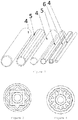
Figures 1-A and 1-B each depict a view of a type of thermal lance like the one of the present invention. -
Figure 2 depicts a view of some of the different types of profiles forming part of the thermal lance of the present invention. -
Figures 3 and 4 depict two embodiments of the lance of the present invention formed from four tubular profiles. -
Figure 5 depicts an embodiment of the lance of the present invention formed from five tubular profiles. -
Figures 6 and 7 depict two embodiments of the lance of the present invention formed from six tubular profiles. -
Figure 8 depicts an embodiment of the lance of the present invention formed from seven tubular profiles. -
Figure 9 depicts an embodiment of the lance of the present invention formed from eight tubular profiles. -
Figure 10 depicts an embodiment of the lance of the present invention formed from ten tubular profiles. -
Figure 11 depicts an embodiment of the lance of the present invention formed from five tubular profiles. - The present invention describes a thermal lance (1) for the fusion cutting and/or piercing of any type of material, for example, for piercing and opening tapping passages in melting furnaces that use plugs made of clay or mixtures of, inter alia, alumina, silica and carbon, comprising at least four tubular profiles, one arranged externally and three arranged internally, and more than seventeen cavities housed inside the lance, where two of the at least four tubular profiles have different cross-sections, wherein each tubular profile is arranged in a contiguous manner in relation to the other tubular profiles, and where each tubular profile is selected from tubular profiles having a circular (4), square (6), triangular (not shown), hexagonal (not shown), oval (not shown), or multi-point star-shaped (5) cross-section.
- One of the at least four tubular profiles forming the thermal lance corresponds to an outer tubular profile and the others correspond to the inner tubular profiles, such that the outer tubular profile is responsible for housing the inner profiles and the cavities that are formed between contiguous profiles.
- In one embodiment of the present invention, the inner profiles are located next to one another, covering the entire inner perimeter of the outer tubular profile.
- In another embodiment of the present invention, the inner profiles are located concentrically in relation to one another and in relation to the outer tubular profile. In this concentric embodiment, each tubular profile forming the lance has a cross-section different from the cross-section of the contiguous profile.
- The cavities housed inside the outer tubular profile correspond to the sum of the cavities of the tubular profiles plus the cavities that are formed between contiguous profiles. All the inner cavities formed inside the lance have varied geometric shapes. The shape of each cavity and the amount of cavities between profiles depends on the shape of the cross-sections of the contiguous profiles. In general, a lance having four or more concentric profiles having multiple vertexes generates from 17 to 100 or more inner cavities. The inner cavities allow the free circulation of oxidizing gases, which are necessary when the thermal lance is in the operating state, the oxidizing gases preferably corresponding to an oxygen stream. The inner cavities allow the oxidizing gas stream to pass through the lance during the operation thereof with a suitable turbulence, and the ratio of the dimensions of these cavities in reference to the wall thicknesses of the tubular profiles is one that achieves the desired lance efficiency.
- The shape, size and number of inner cavities allow the lance to have concentrated effective heating capacity in the center of the lance, whereby generating greater amount of effective heating energy in one and the same cross-section, doubling its efficiency, being able to cut or pierce 100% more with the same grams of lance in relation to current lances, which at the same time entails a reduction of the cutting or piercing time by at least 50%. Furthermore, the lance can be operated using different oxidizing gas streams, keeping the combustion thereof level and constant, and can even be operated with less pure oxygen (90%) and with different oxygen streams (high and low). Unlike current lances in which combustion is not concentrated, but rather randomly occurs at different points of the cross-section, even burning at different points longitudinally, and where furthermore current lances considerably reduce their efficiency, even going out when oxygen with a purity of less than 95% is circulated and when excess oxygen streams are circulated.
- Additionally, the lances of the present invention reduce the emission of polluting gases since they achieve efficient combustion due to the cavities formed, which allow reaching a balance in the contact between the iron and the oxygen stream, and at the same time reducing operating costs because less time and a smaller oxygen stream are required for the cutting or piercing.
- The thickness of each tubular profile is comprised in a range from less than 0.9 mm to more than 3.0 mm. In one embodiment, the thermal lances of the present invention can be made of low-carbon steel.
- In the thermal lances of the present invention, the outer tubular profile forms the casing of the lance and said casing has a uniform or irregular outer structure. The outer body of the lance can have the same cross-section along the entire body thereof or can have more than one cross-section. Likewise, the inner profiles can have the same cross-section along the entire body thereof or can have more than one cross-section. The thermal lances of the present invention can be susceptible to coupling (
Figure 1-A ) or not susceptible to coupling (Figure 1-B ), depending on the shape of their outer ends. A lance susceptible to coupling is one that can be attached to another lance, either directly without the intervention of external means, or through additional means, for example a coupling device or part which allows attaching both lances. -
Figure 1-A shows a type of thermal lance (1) susceptible to coupling, in which the ends of the casing of the lance have been modified such that said ends have an inverted conical shape (2). Furthermore, at each end of the uniform casing, immediately before the inverted conical ends, such lances have a smooth and cylindrical surface and an annular external groove (3). The casing of such lances, as in lances not susceptible to coupling, can have different cross-sections, and the cross-section thereof depends on the cross-section of the outer profile. In one embodiment of such lances, the uniform casing is cylindrical and straight. The outer shape of the ends of such thermal lances of the present invention, allows the easy assembly between one lance and another through a hollow, outer coupling part or device that allows holding a lance at each of its ends. The inverted conical ends of such lances allow facilitating the fitting with the coupling part, and the annular external groove (3) of the lance allows assuring the fitting between the lance and the coupling part. This type of lance corresponds to a lance susceptible to coupling at both its ends. The size of such lances is variable and depends on the application given to the lance, and the location of the outer groove at each end of the lance allows the lances to not interfere with one another when they are coupled together. - In another embodiment, the thermal lances of the present invention that are susceptible to coupling have only one end with an inverted conical shape, which indicates that they can be coupled at only one end. Additionally, at said end of the casing, immediately before the inverted conical end, such lances have a smooth and cylindrical surface and an annular external groove.
- Being able to provide lances coupled to each other allows complete consumption of each lance at the time of being used, such that there are no lance remnants and therefore no losses of material, making the operation more cost-effective. The shape of the ends of the lances and of the coupling parts allows attaching as many lances as required for the purpose of preventing losses of lances.
- In general, the lances can have lengths comprised in the range from less than 1 m to more than 10 m.
- In another embodiment, the thermal lances of the present invention have a coating made from a material having a high melting point (above 2,000°C), such as a ceramic material, which is applied to lances working in sites with temperatures exceeding 1,400°C, thereby preventing the lances from melting and accordingly losing their shape, their capacity for conducting oxidizing gases and their combustion capacity. The coating of the lances can be applied to the outer profile and/or to at least one of the inner profiles.
- The thermal lance of the present invention is obtained by means of applying thermal, mechanical and chemical processes. Each tubular profile before being concentrically fitted is subjected to a metal shaping process, the outer tubular profile preferably being the first to be shaped, and the central inner tubular profile being the last one to be shaped. The amount of tubular profiles to be subjected to the shaping process depends on the design of each lance, i.e., on the amount of profiles required for a specific design of the lance. Additionally, the selection of the amount of tubular profiles that will form a lance depends on the use that will be given to the lance, in general being able to have lances that are 2 mm in diameter up to lances that are 100 mm in diameter.
- Once the shaping process of each tubular profile has ended, forming part of the lance, the shaped profiles are gradually attached to one another by means of thermal, mechanical and chemical processes which, in addition to carrying out the assembly, achieve an interference of measurements between profiles, such that a specific profile is fixed (attached) to the profile right before it, which allows leaving them fixed and secured for withstanding the pressure and the oxidizing gas or oxygen streams passing through the lance during the operation thereof, without one profile becoming detached from another.
-
Figure 2 shows different types of profiles both in terms of the shape of the cross-section and in terms of the inner diameter of each profile. -
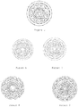
Figure 3 shows an embodiment of the present invention formed by four tubular concentric profiles with seventeen inner cavities. -
Figure 4 shows an embodiment of the present invention formed by four tubular concentric profiles with thirty-seven inner cavities. -
Figure 5 shows an embodiment of the present invention formed by five tubular concentric profiles with forty-one inner cavities. -
Figures 6 and 7 show two embodiments of the present invention formed by six tubular concentric profiles and with multiple inner cavities. -
Figures 8 and 9 show two embodiments of the present invention formed by seven and eight tubular concentric profiles and with multiple inner cavities, respectively. -
Figure 10 shows an embodiment of the present invention formed by ten tubular profiles with seventeen inner cavities. -
Figure 11 shows another embodiment of the present invention formed by five tubular concentric profiles with multiple inner cavities, in which the inner cavities have uniform and nonuniform shapes in relation to one another. - It was surprisingly found that the variation of the amount of profiles forming a lance, together with the variation of the shapes of the profiles and to the sequential order of the profiles inside the lance, allow generating efficient cavities for the passage of the oxidizing gas stream, whereby making better use of the calorific value of the iron housed in the profiles; furthermore, the cross-sections of the profiles used in the conformation of the lance according to the present invention allow a design that obtains, at will, the required flexural strength, achieving, when required, greater strength than that which is obtained with lances of another type having the same mass. Additionally, the geometric configuration obtained in the lance as a whole allows concentrating the point of incidence of the lance with great precision, thereby achieving a more even, cleaner, more accurate and more efficient cutting.
- As a result of the lances of the present invention making better use of the calorific value thereof, the lances of the present invention allow increasing their cutting speed and capacity, whereby reducing the time the operator is exposed to high temperatures, reducing the risk of thermal stress.
- The lances of the present invention have varied uses, for example in the case of cutting copper and slag in sites such as: bears, pigs or settled accretions, furnace windows, furnace floors with brick and copper material, accretions in furnace walls, cleaning in the nozzle housing area, accretions in the gas outlet pre-chamber duct, passage opening, refining and anode furnaces.
- The thermal lances can also be used for cutting that allows efficiently opening passages in, inter alia, copper, steel, ferroalloy, and platinum smelting furnaces, independently of the plugs having any composition, even if they consist of pure graphite (carbon). Likewise, they can be used for the fusion cutting and/or piercing of steels of any grade or thickness, for example 1,000 mm, 2,000 mm, 3,000 mm and thicker. They can also be used for the cutting and/or piercing concrete blocks or rocks and stones of any type and dimension.
- Furthermore, as stated, the thermal lances of the present invention can be used for the fusion cutting and/or piercing of any type of material, even diamond, which is the most temperature-resistant material.
- Some general application examples of the lances of the present invention are:
- Rigid lances generating high heat energy and at the same time delivering a low or nil oxygen stream, for the cutting and/or piercing of non-ferrous materials in an efficient and precise manner.
- Rigid lances generating low heat energy and at the same time delivering a high oxygen stream, for the cutting and/or piercing of ferrous materials in an efficient and precise manner.
- Flexible lances generating high heat energy and at the same time delivering a low or nil oxygen stream, for the cutting and/or piercing of non-ferrous materials in sites with little space requiring the lance to bend.
- Flexible lances generating low heat energy and at the same time delivering a high oxygen stream, for the cutting and/or piercing of ferrous materials in sites with little space requiring the lance to bend.
Claims (15)
- A thermal lance (1) having suitable flexibility and concentrated effective heating capacity for the fusion cutting and/or piercing of any type of material, for example, for piercing and opening tapping passages in melting furnaces that use plugs made of clay or mixtures of, inter alia, alumina, silica and carbon, characterized in that it comprises at least four tubular profiles, one arranged externally and three arranged internally, and more than seventeen cavities housed inside said lance, where at least two of said four tubular profiles have different cross-sections, wherein each tubular profile is arranged in a contiguous manner in relation to the other tubular profiles, and where each tubular profile is selected from tubular profiles having a circular, square, triangular, hexagonal, oval, or multi-point star-shaped cross-section.
- The thermal lance according to claim 1, characterized in that the lance is susceptible to coupling at least at one end.
- The thermal lance according to claim 1, characterized in that the lance is not susceptible to coupling.
- The thermal lance according to any of claims 1 to 3, characterized in that the outer tubular profile and/or the inner profiles have the same cross-section along the entire body thereof.
- The thermal lance according to any of claims 1 to 3, characterized in that the outer tubular profile and/or the inner profiles have more than one cross-section along the entire body thereof.
- The thermal lance according to any of claims 4 or 5, characterized in that the thermal lance comprises at least thirty-seven cavities housed inside said lance.
- The thermal lance according to any of claims 4 or 5, characterized in that the thermal lance comprises at least five tubular profiles, one arranged externally and four arranged internally.
- The thermal lance according to claim 7, characterized in that the thermal lance comprises at least forty-one inner cavities.
- The thermal lance according to any of claims 4 or 5, characterized in that the inner tubular profiles are located next to one another, covering the entire inner perimeter of the outer tubular profile.
- The thermal lance according to any of claims 4 or 5, characterized in that the inner tubular profiles are located concentrically in relation to one another and in relation to the outer tubular profile.
- The thermal lance according to any of claims 4 or 5, characterized in that the thermal lance comprises at least six tubular profiles, preferably at least seven and more preferably at least eight tubular profiles.
- The thermal lance according to claim 3, characterized in that the thermal lance is susceptible to coupling at two ends, therefore on its outer surface or casing said lance has inverted conical ends (2), where furthermore at each end of the casing, immediately before the inverted conical ends, it has a smooth and cylindrical surface which has an annular external groove (3).
- The thermal lance according to claim 12, characterized in that this outer shape of the thermal lance allows the easy assembly between one of said lances and another one of said lances, through a hollow, outer coupling part or device that allows holding a lance at each of its ends, where the inverted conical ends of said lance allow facilitating the fitting with the coupling part, and the annular external groove (3) of said lance allows assuring the fitting between the lance and the coupling device.
- The thermal lance according to claim 3, characterized in that the thermal lance is susceptible to coupling at only one end, therefore on its outer surface or casing said lance has one end with an inverted conical shape, and where furthermore at said end of the casing, immediately before the inverted conical end, it has a smooth and cylindrical surface which has an annular external groove.
- The thermal lance according to any of claims 1 to 14, characterized in that the lance further comprises a ceramic coating when the lance works at temperatures exceeding 1,400°C.
Priority Applications (1)
| Application Number | Priority Date | Filing Date | Title |
|---|---|---|---|
| PL14877664T PL3093426T3 (en) | 2014-01-07 | 2014-12-19 | Thermal lance for fusion cutting and/or piercing, comprising at least four tubular profiles and more than 17 cavities inside the lance |
Applications Claiming Priority (2)
| Application Number | Priority Date | Filing Date | Title |
|---|---|---|---|
| CL2014000034A CL2014000034A1 (en) | 2014-01-07 | 2014-01-07 | Thermal lance for drilling and / or fusion cutting any material, comprises at least 4 tubular profiles, one outer and three inner, and more than 17 cavities inside the lance, at least 2 of the 4 tubular profiles have different cross sections and the profiles are located contiguously; and use of the spear. |
| PCT/CL2014/000082 WO2015103715A1 (en) | 2014-01-07 | 2014-12-19 | Thermal lance for fusion cutting and/or piercing, comprising at least four tubular profiles and more than 17 cavities inside the lance |
Publications (3)
| Publication Number | Publication Date |
|---|---|
| EP3093426A1 EP3093426A1 (en) | 2016-11-16 |
| EP3093426A4 EP3093426A4 (en) | 2017-06-21 |
| EP3093426B1 true EP3093426B1 (en) | 2018-09-19 |
Family
ID=52002244
Family Applications (1)
| Application Number | Title | Priority Date | Filing Date |
|---|---|---|---|
| EP14877664.4A Active EP3093426B1 (en) | 2014-01-07 | 2014-12-19 | Thermal lance for fusion cutting and/or piercing, comprising at least four tubular profiles and more than 17 cavities inside the lance |
Country Status (15)
| Country | Link |
|---|---|
| US (1) | US10048007B2 (en) |
| EP (1) | EP3093426B1 (en) |
| JP (1) | JP2017510777A (en) |
| KR (1) | KR102325559B1 (en) |
| CN (1) | CN105849352B (en) |
| AU (1) | AU2014377303B2 (en) |
| CA (1) | CA2935249C (en) |
| CL (1) | CL2014000034A1 (en) |
| ES (1) | ES2696452T3 (en) |
| MX (1) | MX370353B (en) |
| PE (1) | PE20161157A1 (en) |
| PL (1) | PL3093426T3 (en) |
| RU (1) | RU2692140C2 (en) |
| WO (1) | WO2015103715A1 (en) |
| ZA (1) | ZA201604408B (en) |
Families Citing this family (5)
| Publication number | Priority date | Publication date | Assignee | Title |
|---|---|---|---|---|
| CL2014000034A1 (en) * | 2014-01-07 | 2014-10-03 | Trefimet S A | Thermal lance for drilling and / or fusion cutting any material, comprises at least 4 tubular profiles, one outer and three inner, and more than 17 cavities inside the lance, at least 2 of the 4 tubular profiles have different cross sections and the profiles are located contiguously; and use of the spear. |
| GB201701224D0 (en) * | 2017-01-25 | 2017-03-08 | Cardno Bruce | Downhole operations and associated apparatus |
| CL2017000419A1 (en) * | 2017-02-21 | 2017-12-15 | Trefimet S A | Lanza termica consumible por reaccion exotermica que es utilizada para perforar y/o cortar cualquier tipo de material de diferentes espesores y dimensiones, posee un cuerpo tubular exterior principal y al menos un perfil hueco interior que tiene una seccion transversal diferente dispuestos en forma concentrica formando entre cada uno de los perfiles huecos interiores y/o el cuerpo tubular exterior principal cavidades que configuran pasajes de gas oxidante. |
| WO2019025008A1 (en) * | 2017-08-04 | 2019-02-07 | Wacker Chemie Ag | Wooden casing for oxygen lances |
| CN107560440B (en) * | 2017-09-20 | 2024-04-12 | 中国恩菲工程技术有限公司 | Spray gun head, spray gun with spray gun head and processing method of spray gun head |
Family Cites Families (18)
| Publication number | Priority date | Publication date | Assignee | Title |
|---|---|---|---|---|
| GB1288931A (en) | 1969-01-16 | 1972-09-13 | ||
| US3602620A (en) * | 1969-02-21 | 1971-08-31 | Edwin Eduard Fassler | Thermal lances |
| CH480153A (en) * | 1969-03-21 | 1969-10-31 | Faessler Edwin E | Burning tube for thermal drilling |
| GB1317540A (en) | 1972-07-17 | 1973-05-23 | Intravend Ag | Oxygen or thermic lances |
| CH617613A5 (en) | 1977-03-17 | 1980-06-13 | Bruno P Meyerhans | Oxygen lance and method of manufacturing it |
| SU857473A2 (en) * | 1979-05-03 | 1981-08-23 | Криворожский Ордена Трудового Красного Знамени Горнорудный Институт | Device for thermal breaking of mineral media with jets of high-temperature gas |
| US4401040A (en) | 1981-10-21 | 1983-08-30 | Volcano Corporation | Thermal torch |
| GB8333875D0 (en) | 1983-12-20 | 1984-02-01 | Partington E C | Dual stage combustion system |
| US5000426A (en) * | 1989-08-15 | 1991-03-19 | Edna Corporation | Exothermic cutting torch |
| JP2000071069A (en) * | 1998-08-28 | 2000-03-07 | Fuaiaaransu Kogyo Kk | Lance pipe |
| RU2178505C1 (en) * | 2000-09-18 | 2002-01-20 | Азизов Азиз Мустафаевич | Working member of self-contained drilling apparatus |
| US7273237B1 (en) * | 2005-02-04 | 2007-09-25 | Plattner Wesley M | Union coupler assembly for coolant lines |
| EP1847678A1 (en) * | 2006-04-13 | 2007-10-24 | Air Products and Chemicals, Inc. | A thermic lance |
| US7749427B2 (en) * | 2007-04-27 | 2010-07-06 | P.C. Campana, Inc. | Exothermic cutting torch |
| CN102312041B (en) * | 2011-08-24 | 2013-06-05 | 济南程信利冶金备件有限公司 | Anti-corrosion method for oxygen lance nozzle and oxygen lance nozzle |
| CL2011003331A1 (en) * | 2011-12-28 | 2012-05-11 | Method for manufacturing a thermal lance with continuous retention of its components, wherein said thermal lance is of the type formed by oxidizable internal and external components, axially introducing one or more oxidizable internal components, in an oxidizable tube with a uniform cross section; thermal lance. | |
| US9452487B1 (en) * | 2012-06-21 | 2016-09-27 | Broco, Inc. | Exothermic cutting rod |
| CL2014000034A1 (en) * | 2014-01-07 | 2014-10-03 | Trefimet S A | Thermal lance for drilling and / or fusion cutting any material, comprises at least 4 tubular profiles, one outer and three inner, and more than 17 cavities inside the lance, at least 2 of the 4 tubular profiles have different cross sections and the profiles are located contiguously; and use of the spear. |
-
2014
- 2014-01-07 CL CL2014000034A patent/CL2014000034A1/en unknown
- 2014-12-19 JP JP2016543137A patent/JP2017510777A/en active Pending
- 2014-12-19 ES ES14877664T patent/ES2696452T3/en active Active
- 2014-12-19 MX MX2016008562A patent/MX370353B/en active IP Right Grant
- 2014-12-19 CA CA2935249A patent/CA2935249C/en active Active
- 2014-12-19 EP EP14877664.4A patent/EP3093426B1/en active Active
- 2014-12-19 CN CN201480071983.6A patent/CN105849352B/en active Active
- 2014-12-19 US US15/109,310 patent/US10048007B2/en active Active
- 2014-12-19 PE PE2016000854A patent/PE20161157A1/en unknown
- 2014-12-19 PL PL14877664T patent/PL3093426T3/en unknown
- 2014-12-19 WO PCT/CL2014/000082 patent/WO2015103715A1/en active Application Filing
- 2014-12-19 RU RU2016129982A patent/RU2692140C2/en active
- 2014-12-19 KR KR1020167021467A patent/KR102325559B1/en active IP Right Grant
- 2014-12-19 AU AU2014377303A patent/AU2014377303B2/en active Active
-
2016
- 2016-06-29 ZA ZA2016/04408A patent/ZA201604408B/en unknown
Also Published As
| Publication number | Publication date |
|---|---|
| RU2692140C2 (en) | 2019-06-21 |
| EP3093426A4 (en) | 2017-06-21 |
| CA2935249A1 (en) | 2015-07-16 |
| US20160341478A1 (en) | 2016-11-24 |
| KR102325559B1 (en) | 2021-11-12 |
| MX370353B (en) | 2019-12-10 |
| AU2014377303A1 (en) | 2016-07-21 |
| CN105849352B (en) | 2019-03-12 |
| PL3093426T3 (en) | 2019-09-30 |
| RU2016129982A (en) | 2018-02-16 |
| KR20160106143A (en) | 2016-09-09 |
| CL2014000034A1 (en) | 2014-10-03 |
| ES2696452T3 (en) | 2019-01-15 |
| RU2016129982A3 (en) | 2018-10-01 |
| EP3093426A1 (en) | 2016-11-16 |
| PE20161157A1 (en) | 2016-11-03 |
| AU2014377303B2 (en) | 2018-09-06 |
| US10048007B2 (en) | 2018-08-14 |
| ZA201604408B (en) | 2017-07-26 |
| MX2016008562A (en) | 2016-09-26 |
| CN105849352A (en) | 2016-08-10 |
| WO2015103715A1 (en) | 2015-07-16 |
| CA2935249C (en) | 2020-11-10 |
| JP2017510777A (en) | 2017-04-13 |
Similar Documents
| Publication | Publication Date | Title |
|---|---|---|
| EP3093426B1 (en) | Thermal lance for fusion cutting and/or piercing, comprising at least four tubular profiles and more than 17 cavities inside the lance | |
| US4469932A (en) | Plasma burner operated by means of gaseous mixtures | |
| JP2017510777A5 (en) | ||
| US4289949A (en) | Plasma burners | |
| CN102338561A (en) | Foamed ceramic gas crucible | |
| NO862016L (en) | PLASMA TORCH. | |
| AU2021215276A1 (en) | Quick-coupling device comprising a hollow cylinder having bevelled ends and two circular internal grooves | |
| US3921542A (en) | Oxygen supplied thermal lance | |
| CN210198159U (en) | High-strength honeycomb ceramic heat accumulator | |
| CA3016938C (en) | Furnace burner | |
| CA3054372A1 (en) | Thermal lance comprising at least one hollow tubular profile made of aluminium and/or magnesium, among other materials, which allows same to be used in processes requiring a largeamount of energy to cut, perforate, and/or melt materials having a high thermal requirement | |
| BR112016015523B1 (en) | THERMAL BOOM FOR DRILLING AND/OR FUSION CUTTING | |
| JP6181843B1 (en) | Lance pipe for oxygen lance | |
| Khan et al. | Design and development of low scale, high temperature, hybrid furnace for the extraction of metallurgical grade silicon from raw mineral quartz | |
| Friedrich | Selecting the optimum electrode diameter for AC EAFs | |
| JPH0240475Y2 (en) | ||
| Candea et al. | THERMAL CUTTING EQUIPMENT FOR CONSTRUCTION MATERIALS WITH THERMAL LANCING | |
| Sylvén et al. | Advanced Oxygen Lances for Safer Furnace Tapping Operations | |
| JPH03313Y2 (en) | ||
| RU2280545C2 (en) | Torch for electric arc gas-shield welding by means of non-consumable electrode | |
| UA56726C2 (en) | Guinite tuyere for hot fixing of industrial furnaces by ceramic melting |
Legal Events
| Date | Code | Title | Description |
|---|---|---|---|
| PUAI | Public reference made under article 153(3) epc to a published international application that has entered the european phase |
Free format text: ORIGINAL CODE: 0009012 |
|
| 17P | Request for examination filed |
Effective date: 20160718 |
|
| AK | Designated contracting states |
Kind code of ref document: A1 Designated state(s): AL AT BE BG CH CY CZ DE DK EE ES FI FR GB GR HR HU IE IS IT LI LT LU LV MC MK MT NL NO PL PT RO RS SE SI SK SM TR |
|
| AX | Request for extension of the european patent |
Extension state: BA ME |
|
| DAX | Request for extension of the european patent (deleted) | ||
| A4 | Supplementary search report drawn up and despatched |
Effective date: 20170518 |
|
| RIC1 | Information provided on ipc code assigned before grant |
Ipc: E21B 7/14 20060101AFI20170512BHEP |
|
| GRAP | Despatch of communication of intention to grant a patent |
Free format text: ORIGINAL CODE: EPIDOSNIGR1 |
|
| INTG | Intention to grant announced |
Effective date: 20180406 |
|
| GRAS | Grant fee paid |
Free format text: ORIGINAL CODE: EPIDOSNIGR3 |
|
| GRAA | (expected) grant |
Free format text: ORIGINAL CODE: 0009210 |
|
| AK | Designated contracting states |
Kind code of ref document: B1 Designated state(s): AL AT BE BG CH CY CZ DE DK EE ES FI FR GB GR HR HU IE IS IT LI LT LU LV MC MK MT NL NO PL PT RO RS SE SI SK SM TR |
|
| REG | Reference to a national code |
Ref country code: GB Ref legal event code: FG4D |
|
| REG | Reference to a national code |
Ref country code: CH Ref legal event code: EP |
|
| REG | Reference to a national code |
Ref country code: AT Ref legal event code: REF Ref document number: 1043461 Country of ref document: AT Kind code of ref document: T Effective date: 20181015 |
|
| REG | Reference to a national code |
Ref country code: IE Ref legal event code: FG4D |
|
| REG | Reference to a national code |
Ref country code: DE Ref legal event code: R096 Ref document number: 602014032815 Country of ref document: DE |
|
| REG | Reference to a national code |
Ref country code: NL Ref legal event code: FP |
|
| RAP2 | Party data changed (patent owner data changed or rights of a patent transferred) |
Owner name: TREFIMET S.A. |
|
| REG | Reference to a national code |
Ref country code: DE Ref legal event code: R081 Ref document number: 602014032815 Country of ref document: DE Owner name: TREFIMET S.A., CL Free format text: FORMER OWNER: TREFIMET S.A., SANTIAGO, CL |
|
| REG | Reference to a national code |
Ref country code: ES Ref legal event code: FG2A Ref document number: 2696452 Country of ref document: ES Kind code of ref document: T3 Effective date: 20190115 |
|
| REG | Reference to a national code |
Ref country code: SE Ref legal event code: TRGR |
|
| PG25 | Lapsed in a contracting state [announced via postgrant information from national office to epo] |
Ref country code: RS Free format text: LAPSE BECAUSE OF FAILURE TO SUBMIT A TRANSLATION OF THE DESCRIPTION OR TO PAY THE FEE WITHIN THE PRESCRIBED TIME-LIMIT Effective date: 20180919 Ref country code: LT Free format text: LAPSE BECAUSE OF FAILURE TO SUBMIT A TRANSLATION OF THE DESCRIPTION OR TO PAY THE FEE WITHIN THE PRESCRIBED TIME-LIMIT Effective date: 20180919 |
|
| REG | Reference to a national code |
Ref country code: LT Ref legal event code: MG4D Ref country code: NO Ref legal event code: T2 Effective date: 20180919 |
|
| PG25 | Lapsed in a contracting state [announced via postgrant information from national office to epo] |
Ref country code: AL Free format text: LAPSE BECAUSE OF FAILURE TO SUBMIT A TRANSLATION OF THE DESCRIPTION OR TO PAY THE FEE WITHIN THE PRESCRIBED TIME-LIMIT Effective date: 20180919 Ref country code: HR Free format text: LAPSE BECAUSE OF FAILURE TO SUBMIT A TRANSLATION OF THE DESCRIPTION OR TO PAY THE FEE WITHIN THE PRESCRIBED TIME-LIMIT Effective date: 20180919 Ref country code: LV Free format text: LAPSE BECAUSE OF FAILURE TO SUBMIT A TRANSLATION OF THE DESCRIPTION OR TO PAY THE FEE WITHIN THE PRESCRIBED TIME-LIMIT Effective date: 20180919 |
|
| REG | Reference to a national code |
Ref country code: AT Ref legal event code: MK05 Ref document number: 1043461 Country of ref document: AT Kind code of ref document: T Effective date: 20180919 |
|
| REG | Reference to a national code |
Ref country code: SK Ref legal event code: T3 Ref document number: E 29334 Country of ref document: SK |
|
| PG25 | Lapsed in a contracting state [announced via postgrant information from national office to epo] |
Ref country code: EE Free format text: LAPSE BECAUSE OF FAILURE TO SUBMIT A TRANSLATION OF THE DESCRIPTION OR TO PAY THE FEE WITHIN THE PRESCRIBED TIME-LIMIT Effective date: 20180919 Ref country code: RO Free format text: LAPSE BECAUSE OF FAILURE TO SUBMIT A TRANSLATION OF THE DESCRIPTION OR TO PAY THE FEE WITHIN THE PRESCRIBED TIME-LIMIT Effective date: 20180919 Ref country code: CZ Free format text: LAPSE BECAUSE OF FAILURE TO SUBMIT A TRANSLATION OF THE DESCRIPTION OR TO PAY THE FEE WITHIN THE PRESCRIBED TIME-LIMIT Effective date: 20180919 Ref country code: AT Free format text: LAPSE BECAUSE OF FAILURE TO SUBMIT A TRANSLATION OF THE DESCRIPTION OR TO PAY THE FEE WITHIN THE PRESCRIBED TIME-LIMIT Effective date: 20180919 |
|
| PG25 | Lapsed in a contracting state [announced via postgrant information from national office to epo] |
Ref country code: SM Free format text: LAPSE BECAUSE OF FAILURE TO SUBMIT A TRANSLATION OF THE DESCRIPTION OR TO PAY THE FEE WITHIN THE PRESCRIBED TIME-LIMIT Effective date: 20180919 Ref country code: PT Free format text: LAPSE BECAUSE OF FAILURE TO SUBMIT A TRANSLATION OF THE DESCRIPTION OR TO PAY THE FEE WITHIN THE PRESCRIBED TIME-LIMIT Effective date: 20190119 |
|
| REG | Reference to a national code |
Ref country code: DE Ref legal event code: R097 Ref document number: 602014032815 Country of ref document: DE |
|
| PLBE | No opposition filed within time limit |
Free format text: ORIGINAL CODE: 0009261 |
|
| STAA | Information on the status of an ep patent application or granted ep patent |
Free format text: STATUS: NO OPPOSITION FILED WITHIN TIME LIMIT |
|
| PG25 | Lapsed in a contracting state [announced via postgrant information from national office to epo] |
Ref country code: DK Free format text: LAPSE BECAUSE OF FAILURE TO SUBMIT A TRANSLATION OF THE DESCRIPTION OR TO PAY THE FEE WITHIN THE PRESCRIBED TIME-LIMIT Effective date: 20180919 |
|
| REG | Reference to a national code |
Ref country code: CH Ref legal event code: PL |
|
| 26N | No opposition filed |
Effective date: 20190620 |
|
| PG25 | Lapsed in a contracting state [announced via postgrant information from national office to epo] |
Ref country code: MC Free format text: LAPSE BECAUSE OF FAILURE TO SUBMIT A TRANSLATION OF THE DESCRIPTION OR TO PAY THE FEE WITHIN THE PRESCRIBED TIME-LIMIT Effective date: 20180919 Ref country code: LU Free format text: LAPSE BECAUSE OF NON-PAYMENT OF DUE FEES Effective date: 20181219 |
|
| REG | Reference to a national code |
Ref country code: IE Ref legal event code: MM4A |
|
| PG25 | Lapsed in a contracting state [announced via postgrant information from national office to epo] |
Ref country code: SI Free format text: LAPSE BECAUSE OF FAILURE TO SUBMIT A TRANSLATION OF THE DESCRIPTION OR TO PAY THE FEE WITHIN THE PRESCRIBED TIME-LIMIT Effective date: 20180919 Ref country code: IE Free format text: LAPSE BECAUSE OF NON-PAYMENT OF DUE FEES Effective date: 20181219 |
|
| PG25 | Lapsed in a contracting state [announced via postgrant information from national office to epo] |
Ref country code: LI Free format text: LAPSE BECAUSE OF NON-PAYMENT OF DUE FEES Effective date: 20181231 Ref country code: CH Free format text: LAPSE BECAUSE OF NON-PAYMENT OF DUE FEES Effective date: 20181231 |
|
| PG25 | Lapsed in a contracting state [announced via postgrant information from national office to epo] |
Ref country code: MT Free format text: LAPSE BECAUSE OF NON-PAYMENT OF DUE FEES Effective date: 20181219 |
|
| PG25 | Lapsed in a contracting state [announced via postgrant information from national office to epo] |
Ref country code: CY Free format text: LAPSE BECAUSE OF FAILURE TO SUBMIT A TRANSLATION OF THE DESCRIPTION OR TO PAY THE FEE WITHIN THE PRESCRIBED TIME-LIMIT Effective date: 20180919 Ref country code: MK Free format text: LAPSE BECAUSE OF NON-PAYMENT OF DUE FEES Effective date: 20180919 Ref country code: HU Free format text: LAPSE BECAUSE OF FAILURE TO SUBMIT A TRANSLATION OF THE DESCRIPTION OR TO PAY THE FEE WITHIN THE PRESCRIBED TIME-LIMIT; INVALID AB INITIO Effective date: 20141219 Ref country code: GR Free format text: LAPSE BECAUSE OF FAILURE TO SUBMIT A TRANSLATION OF THE DESCRIPTION OR TO PAY THE FEE WITHIN THE PRESCRIBED TIME-LIMIT Effective date: 20180919 |
|
| PGFP | Annual fee paid to national office [announced via postgrant information from national office to epo] |
Ref country code: SK Payment date: 20221205 Year of fee payment: 9 Ref country code: SE Payment date: 20221227 Year of fee payment: 9 Ref country code: NO Payment date: 20221228 Year of fee payment: 9 Ref country code: NL Payment date: 20221226 Year of fee payment: 9 Ref country code: GB Payment date: 20221227 Year of fee payment: 9 Ref country code: FR Payment date: 20221227 Year of fee payment: 9 Ref country code: FI Payment date: 20221227 Year of fee payment: 9 Ref country code: BG Payment date: 20221212 Year of fee payment: 9 |
|
| PGFP | Annual fee paid to national office [announced via postgrant information from national office to epo] |
Ref country code: PL Payment date: 20221201 Year of fee payment: 9 Ref country code: BE Payment date: 20221227 Year of fee payment: 9 |
|
| PGFP | Annual fee paid to national office [announced via postgrant information from national office to epo] |
Ref country code: TR Payment date: 20221219 Year of fee payment: 9 Ref country code: ES Payment date: 20230119 Year of fee payment: 9 |
|
| PGFP | Annual fee paid to national office [announced via postgrant information from national office to epo] |
Ref country code: IT Payment date: 20221221 Year of fee payment: 9 Ref country code: IS Payment date: 20230115 Year of fee payment: 9 Ref country code: DE Payment date: 20221228 Year of fee payment: 9 |