JP2017508539A - Lower eyelid treatment - Google Patents
Lower eyelid treatment Download PDFInfo
- Publication number
- JP2017508539A JP2017508539A JP2016558129A JP2016558129A JP2017508539A JP 2017508539 A JP2017508539 A JP 2017508539A JP 2016558129 A JP2016558129 A JP 2016558129A JP 2016558129 A JP2016558129 A JP 2016558129A JP 2017508539 A JP2017508539 A JP 2017508539A
- Authority
- JP
- Japan
- Prior art keywords
- movement
- reference point
- lower eyelid
- protruding shape
- skin
- Prior art date
- Legal status (The legal status is an assumption and is not a legal conclusion. Google has not performed a legal analysis and makes no representation as to the accuracy of the status listed.)
- Withdrawn
Links
- 210000000744 eyelid Anatomy 0.000 title claims abstract description 73
- 230000000737 periodic effect Effects 0.000 claims abstract description 41
- 238000000034 method Methods 0.000 claims abstract description 12
- 210000002751 lymph Anatomy 0.000 claims abstract description 9
- 210000001165 lymph node Anatomy 0.000 claims abstract description 9
- 125000006850 spacer group Chemical group 0.000 claims description 14
- 210000004209 hair Anatomy 0.000 claims description 13
- 230000007246 mechanism Effects 0.000 claims description 10
- 239000002537 cosmetic Substances 0.000 claims description 6
- 230000004044 response Effects 0.000 claims description 4
- 238000003825 pressing Methods 0.000 claims description 2
- 230000003796 beauty Effects 0.000 claims 1
- 238000007665 sagging Methods 0.000 abstract description 12
- 239000012530 fluid Substances 0.000 abstract description 6
- 230000009467 reduction Effects 0.000 abstract description 5
- 210000003491 skin Anatomy 0.000 description 90
- 210000003128 head Anatomy 0.000 description 4
- 210000002615 epidermis Anatomy 0.000 description 3
- 210000001365 lymphatic vessel Anatomy 0.000 description 3
- 230000000007 visual effect Effects 0.000 description 3
- 230000008901 benefit Effects 0.000 description 2
- 230000001926 lymphatic effect Effects 0.000 description 2
- 239000000463 material Substances 0.000 description 2
- 230000008961 swelling Effects 0.000 description 2
- LFQSCWFLJHTTHZ-UHFFFAOYSA-N Ethanol Chemical compound CCO LFQSCWFLJHTTHZ-UHFFFAOYSA-N 0.000 description 1
- 241000282412 Homo Species 0.000 description 1
- 208000010340 Sleep Deprivation Diseases 0.000 description 1
- 230000009471 action Effects 0.000 description 1
- 239000008280 blood Substances 0.000 description 1
- 210000004369 blood Anatomy 0.000 description 1
- 238000004140 cleaning Methods 0.000 description 1
- 238000004891 communication Methods 0.000 description 1
- 230000001419 dependent effect Effects 0.000 description 1
- 230000037213 diet Effects 0.000 description 1
- 235000005911 diet Nutrition 0.000 description 1
- 230000000694 effects Effects 0.000 description 1
- 239000013013 elastic material Substances 0.000 description 1
- 239000007788 liquid Substances 0.000 description 1
- 238000005259 measurement Methods 0.000 description 1
- 239000002184 metal Substances 0.000 description 1
- 230000004089 microcirculation Effects 0.000 description 1
- 239000012858 resilient material Substances 0.000 description 1
- 210000001732 sebaceous gland Anatomy 0.000 description 1
- 239000011343 solid material Substances 0.000 description 1
- 210000000434 stratum corneum Anatomy 0.000 description 1
- 239000000126 substance Substances 0.000 description 1
- 230000001960 triggered effect Effects 0.000 description 1
Images


Classifications
-
- A—HUMAN NECESSITIES
- A61—MEDICAL OR VETERINARY SCIENCE; HYGIENE
- A61H—PHYSICAL THERAPY APPARATUS, e.g. DEVICES FOR LOCATING OR STIMULATING REFLEX POINTS IN THE BODY; ARTIFICIAL RESPIRATION; MASSAGE; BATHING DEVICES FOR SPECIAL THERAPEUTIC OR HYGIENIC PURPOSES OR SPECIFIC PARTS OF THE BODY
- A61H15/00—Massage by means of rollers, balls, e.g. inflatable, chains, or roller chains
- A61H15/0078—Massage by means of rollers, balls, e.g. inflatable, chains, or roller chains power-driven
- A61H15/0085—Massage by means of rollers, balls, e.g. inflatable, chains, or roller chains power-driven hand-held
-
- A—HUMAN NECESSITIES
- A61—MEDICAL OR VETERINARY SCIENCE; HYGIENE
- A61H—PHYSICAL THERAPY APPARATUS, e.g. DEVICES FOR LOCATING OR STIMULATING REFLEX POINTS IN THE BODY; ARTIFICIAL RESPIRATION; MASSAGE; BATHING DEVICES FOR SPECIAL THERAPEUTIC OR HYGIENIC PURPOSES OR SPECIFIC PARTS OF THE BODY
- A61H15/00—Massage by means of rollers, balls, e.g. inflatable, chains, or roller chains
- A61H15/0092—Massage by means of rollers, balls, e.g. inflatable, chains, or roller chains hand-held
-
- A—HUMAN NECESSITIES
- A61—MEDICAL OR VETERINARY SCIENCE; HYGIENE
- A61H—PHYSICAL THERAPY APPARATUS, e.g. DEVICES FOR LOCATING OR STIMULATING REFLEX POINTS IN THE BODY; ARTIFICIAL RESPIRATION; MASSAGE; BATHING DEVICES FOR SPECIAL THERAPEUTIC OR HYGIENIC PURPOSES OR SPECIFIC PARTS OF THE BODY
- A61H15/00—Massage by means of rollers, balls, e.g. inflatable, chains, or roller chains
- A61H2015/0007—Massage by means of rollers, balls, e.g. inflatable, chains, or roller chains with balls or rollers rotating about their own axis
- A61H2015/0014—Massage by means of rollers, balls, e.g. inflatable, chains, or roller chains with balls or rollers rotating about their own axis cylinder-like, i.e. rollers
- A61H2015/0021—Massage by means of rollers, balls, e.g. inflatable, chains, or roller chains with balls or rollers rotating about their own axis cylinder-like, i.e. rollers multiple on the same axis
-
- A—HUMAN NECESSITIES
- A61—MEDICAL OR VETERINARY SCIENCE; HYGIENE
- A61H—PHYSICAL THERAPY APPARATUS, e.g. DEVICES FOR LOCATING OR STIMULATING REFLEX POINTS IN THE BODY; ARTIFICIAL RESPIRATION; MASSAGE; BATHING DEVICES FOR SPECIAL THERAPEUTIC OR HYGIENIC PURPOSES OR SPECIFIC PARTS OF THE BODY
- A61H2201/00—Characteristics of apparatus not provided for in the preceding codes
- A61H2201/12—Driving means
- A61H2201/1207—Driving means with electric or magnetic drive
- A61H2201/1215—Rotary drive
- A61H2201/1223—Frequency controlled AC motor
-
- A—HUMAN NECESSITIES
- A61—MEDICAL OR VETERINARY SCIENCE; HYGIENE
- A61H—PHYSICAL THERAPY APPARATUS, e.g. DEVICES FOR LOCATING OR STIMULATING REFLEX POINTS IN THE BODY; ARTIFICIAL RESPIRATION; MASSAGE; BATHING DEVICES FOR SPECIAL THERAPEUTIC OR HYGIENIC PURPOSES OR SPECIFIC PARTS OF THE BODY
- A61H2201/00—Characteristics of apparatus not provided for in the preceding codes
- A61H2201/16—Physical interface with patient
- A61H2201/1683—Surface of interface
- A61H2201/169—Physical characteristics of the surface, e.g. material, relief, texture or indicia
-
- A—HUMAN NECESSITIES
- A61—MEDICAL OR VETERINARY SCIENCE; HYGIENE
- A61H—PHYSICAL THERAPY APPARATUS, e.g. DEVICES FOR LOCATING OR STIMULATING REFLEX POINTS IN THE BODY; ARTIFICIAL RESPIRATION; MASSAGE; BATHING DEVICES FOR SPECIAL THERAPEUTIC OR HYGIENIC PURPOSES OR SPECIFIC PARTS OF THE BODY
- A61H2201/00—Characteristics of apparatus not provided for in the preceding codes
- A61H2201/50—Control means thereof
- A61H2201/5058—Sensors or detectors
- A61H2201/5061—Force sensors
-
- A—HUMAN NECESSITIES
- A61—MEDICAL OR VETERINARY SCIENCE; HYGIENE
- A61H—PHYSICAL THERAPY APPARATUS, e.g. DEVICES FOR LOCATING OR STIMULATING REFLEX POINTS IN THE BODY; ARTIFICIAL RESPIRATION; MASSAGE; BATHING DEVICES FOR SPECIAL THERAPEUTIC OR HYGIENIC PURPOSES OR SPECIFIC PARTS OF THE BODY
- A61H2201/00—Characteristics of apparatus not provided for in the preceding codes
- A61H2201/50—Control means thereof
- A61H2201/5058—Sensors or detectors
- A61H2201/5071—Pressure sensors
-
- A—HUMAN NECESSITIES
- A61—MEDICAL OR VETERINARY SCIENCE; HYGIENE
- A61H—PHYSICAL THERAPY APPARATUS, e.g. DEVICES FOR LOCATING OR STIMULATING REFLEX POINTS IN THE BODY; ARTIFICIAL RESPIRATION; MASSAGE; BATHING DEVICES FOR SPECIAL THERAPEUTIC OR HYGIENIC PURPOSES OR SPECIFIC PARTS OF THE BODY
- A61H2201/00—Characteristics of apparatus not provided for in the preceding codes
- A61H2201/50—Control means thereof
- A61H2201/5058—Sensors or detectors
- A61H2201/5079—Velocity sensors
-
- A—HUMAN NECESSITIES
- A61—MEDICAL OR VETERINARY SCIENCE; HYGIENE
- A61H—PHYSICAL THERAPY APPARATUS, e.g. DEVICES FOR LOCATING OR STIMULATING REFLEX POINTS IN THE BODY; ARTIFICIAL RESPIRATION; MASSAGE; BATHING DEVICES FOR SPECIAL THERAPEUTIC OR HYGIENIC PURPOSES OR SPECIFIC PARTS OF THE BODY
- A61H2205/00—Devices for specific parts of the body
- A61H2205/02—Head
- A61H2205/022—Face
- A61H2205/024—Eyes
Abstract
本発明は、下まぶた処置装置であって、該装置の皮膚処置領域8における固定された基準点Pを通る周期的な第1の動きを実行することが可能な突出形状を持つ皮膚処置構造3を有する、下まぶた処置装置1に関する。該周期的な第1の動きは、0.5Hzと3.0Hzとの間の周波数範囲内の周波数で基準点Pにおいて生じる。該周期的な第1の動きは、該突出形状の局所的な突出方向に対して横方向の基準点Pにおける単一の局所的な動き方向において、0.005m/secと0.05m/secとの間の速度範囲内の速度での、基準点Pを通る該突出形状の局所的な動きである。このようにして、該装置は、処置される人物の目の下のたるみの特定のマッサージを提供する。該マッサージは、下まぶた領域52の皮膚に望ましくなく溜まった流体の、耳の近くのリンパ節へのリンパ排液に帰着する。斯くして該装置は、目の下のたるみの低減を信頼性高く且つ効果的に促進するための、迅速で容易に使用可能な方法を提供する。The present invention is a lower eyelid treatment device having a protruding shape capable of performing a first periodic movement through a fixed reference point P in a skin treatment region 8 of the device. The lower eyelid treatment apparatus 1 is provided. The periodic first movement occurs at the reference point P at a frequency within a frequency range between 0.5 Hz and 3.0 Hz. The periodic first movement is 0.005 m / sec and 0.05 m / sec in a single local movement direction at a reference point P transverse to the local protrusion direction of the protrusion shape. Is the local movement of the protruding shape through the reference point P at a velocity in the velocity range between. In this way, the device provides a specific massage of sagging under the eyes of the person being treated. The massage results in lymph drainage of fluid that has undesirably accumulated in the skin of the lower eyelid region 52 to the lymph nodes near the ear. Thus, the device provides a quick and easy-to-use method to reliably and effectively promote the reduction of sagging under the eyes.
Description
本発明は、下まぶた処置装置に関する。より詳細には、本発明は、人間の目の下に生じ得るたるみを低減させるための、下まぶた処置装置に関する。本発明はまた、下まぶたの外観を美しくするための美容方法であって、斯かる下まぶた処置装置の使用を有する方法に関する。 The present invention relates to a lower eyelid treatment apparatus. More particularly, the present invention relates to a lower eyelid treatment device for reducing sagging that may occur under the human eye. The invention also relates to a cosmetic method for beautifying the appearance of the lower eyelid, comprising the use of such a lower eyelid treatment device.
人間の目の下のたるみは、しばしば朝に見られる。この朝の腫れは、目の下のたるみの過渡的な形態である。この腫れは、睡眠の間の流体の保持に関連する。睡眠不足及び/又はアルコールの摂取及び/又は運動不足及び/又は塩分の多い食事のようなものに特徴付けられる特定の生活様式が、しばしばこの種の目の下のたるみの外観を悪化させ得る。 Sagging under human eyes is often seen in the morning. This morning swelling is a transitional form of sagging under the eyes. This swelling is associated with fluid retention during sleep. Certain lifestyles characterized by things like sleep deprivation and / or alcohol consumption and / or lack of exercise and / or a salty diet can often exacerbate the appearance of this type of under-eye sag.
速度及び/又はたるみ低減の程度の点で、数あるなかでも下まぶたの皮膚の手による特定のタイプのマッサージが、目の下のたるみの低減を促進させ得る。 In terms of speed and / or degree of sagging reduction, certain types of massage with the lower eyelid skin hand, among others, can help reduce sagging under the eyes.
しかしながら、斯かる手によるマッサージを信頼性高く且つ効果的に行うことは、マッサージ手法の適切な知識を必要とし、非常に時間を要する。多くの人は、適切なマッサージを行うための知識も時間も(特に朝の忙しい時間帯には)持たない。 However, performing such a hand massage reliably and effectively requires appropriate knowledge of the massage technique and is very time consuming. Many people do not have the knowledge or time to do a proper massage (especially during the busy morning hours).
国際特許出願公開WO2010/149959A1は、まぶたをマッサージするための装置を開示している。該装置は、回転可能なマッサージボビンと、該ボビンと熱的に連通した加熱器とを有する。該ボビンは、該ボビンの凹状の外側面から延在する、複数のマッサージ要素を持つ。使用時には、該ボビンがまぶたと接触させられ、該ボビンがまぶたを加熱し、打ちつけ線に垂直にマッサージ力がまぶたにかけられるように回転し、打ちつけ線に向かうマッサージ動作が提供される。該マッサージ力は、まぶたの詰まった皮脂腺から物質を絞り出すために利用される。該マッサージ要素は、該マッサージボビンの周縁部のまわりに延在する連続的な細い螺旋状の隆線と、複数の変形可能な指型の突起の形をとる擦り要素とを有する。 International Patent Application Publication No. WO2010 / 149959A1 discloses a device for massaging the eyelids. The apparatus includes a rotatable massage bobbin and a heater in thermal communication with the bobbin. The bobbin has a plurality of massage elements that extend from the concave outer surface of the bobbin. In use, the bobbin is brought into contact with the eyelid, the bobbin heats the eyelid, rotates so that a massage force is applied to the eyelid perpendicular to the strike line, and provides a massage action toward the strike line. The massage force is used to squeeze out the substance from the sebaceous glands clogged with eyelids. The massage element has a continuous thin spiral ridge extending around the periphery of the massage bobbin and a rubbing element in the form of a plurality of deformable finger-shaped protrusions.
仏国特許出願公開FR2947723A1は、まぶたをマッサージするためのマッサージ装置を開示している。該装置は、ハンドル部と、該ハンドル部の遠位端に備えられた固定シャフトにより回転可能に担持されたマッサージヘッドとを有する。該マッサージヘッドは、複数の突出部を有する。該装置が皮膚面の上に転がされると、該マッサージヘッドが該固定シャフトのまわりに回転させられる。ハンドル部において振動源が備えられ、使用の間に該マッサージヘッドの振動を生成する。 French patent application FR2947723A1 discloses a massage device for massaging the eyelids. The apparatus has a handle portion and a massage head rotatably supported by a fixed shaft provided at a distal end of the handle portion. The massage head has a plurality of protrusions. As the device is rolled over the skin surface, the massage head is rotated around the fixed shaft. A vibration source is provided at the handle portion to generate vibration of the massage head during use.
本発明の目的は、速度及びたるみの低減の程度の点で、信頼性高く且つ効果的に目の下のたるみの低減を促進するための、人間により迅速に且つ容易に用いられることができる方法を提供することにある。 The object of the present invention is to provide a method that can be used quickly and easily by humans to promote the reduction of sagging under the eyes reliably and effectively in terms of speed and the degree of sagging reduction. There is to do.
この目的のため、本発明は、下まぶた処置装置であって、前記装置は、
前記装置を手で保持するための把持領域を有する外側面と、
前記装置の皮膚処置領域において人間の皮膚を接触するための皮膚接触構造であって、前記皮膚処置領域は、前記把持領域に対して固定された位置に基準点を持ち、前記皮膚処置構造は、前記基準点に対して駆動的に可動である、皮膚処置構造と、
電気エネルギー源及び/又は電気エネルギー供給接続部と、
前記電気エネルギー源及び/又は前記電気エネルギー供給接続部に電気的に接続されたモータと、
前記基準点に対する前記皮膚処置構造の駆動された動きを実現するための、前記皮膚処置構造に接続された運動機構であって、前記モータが前記運動機構に駆動的に接続された、運動機構と、
前記駆動された動きに応じて前記皮膚処置構造を動かすよう、前記運動機構を駆動させるよう、前記モータを少なくとも制御するよう構成されたコントローラと、
を有し、
前記皮膚処置構造の駆動された動きは、前記基準点を通る前記皮膚処置構造の突出形状の周期的な第1の動きを有し、前記皮膚処置領域における前記突出形状は、前記基準点を通る前記記突出形状の前記周期的な第1の動きの間少なくとも一時的に局所的な突出方向に前記装置の外側へと局所的に突出し、前記周期的な第1の動きは、前記突出形状の局所的な突出方向に対して横方向の前記基準点における単一の局所的な動き方向において前記基準点を通る前記突出形状の局所的な動きであり、
前記基準点を通る前記周期的な第1の動きは、0.5Hzと3.0Hzとの間の周波数範囲内の周波数で前記基準点において生じ、
前記基準点を通る前記突出形状の前記局所的な動きは、0.005m/secと0.05m/secとの間の速度範囲内の、前記基準点における速度を持つ、下まぶた処置装置を提供する。
For this purpose, the present invention is a lower eyelid treatment device, which device comprises:
An outer surface having a gripping area for holding the device by hand;
A skin contact structure for contacting human skin in the skin treatment area of the device, the skin treatment area having a reference point at a fixed position relative to the gripping area, the skin treatment structure comprising: A skin treatment structure that is drivably movable relative to the reference point;
An electrical energy source and / or an electrical energy supply connection;
A motor electrically connected to the electrical energy source and / or the electrical energy supply connection;
An exercise mechanism connected to the skin treatment structure for realizing a driven movement of the skin treatment structure relative to the reference point, wherein the motor is drivingly connected to the exercise mechanism; ,
A controller configured to at least control the motor to drive the motion mechanism to move the skin treatment structure in response to the driven movement;
Have
The driven movement of the skin treatment structure has a periodic first movement of the protruding shape of the skin treatment structure through the reference point, and the protruding shape in the skin treatment region passes through the reference point. During the periodic first movement of the protruding shape, the protrusion protrudes locally at least temporarily in the local protruding direction to the outside of the device, the periodic first movement of the protruding shape A local movement of the protruding shape through the reference point in a single local movement direction at the reference point transverse to the local protruding direction;
The periodic first movement through the reference point occurs at the reference point at a frequency within a frequency range between 0.5 Hz and 3.0 Hz;
Providing a lower eyelid treatment device, wherein the local movement of the protruding shape through the reference point has a velocity at the reference point within a velocity range between 0.005 m / sec and 0.05 m / sec. To do.
本発明による装置は、該装置の皮膚処置領域において、該装置の皮膚処置構造が、人間の顔の下まぶた領域に当たるような態様で、手で保持されることができる。この状態においては、動作中の該装置は、下まぶた領域の皮膚において望ましくなく構築された流体(リンパ排液)の輸送に帰着する、目の下のたるみに対する特定のマッサージ処置を提供することが可能である。この流体の輸送は、人間の皮膚に圧力をかける、該装置の皮膚処置構造の突出形状の、周期的な第1の動きによって引き起こされ、同時に、該突出形状は、それぞれ前記周波数範囲及び前記速度範囲内の周波数及び速度で、該装置の皮膚処置領域の基準点でみて、前記単一の局所的な動き方向において該基準位置を通って周期的に動く。実際に、該突出形状により為される皮膚における各感触は、手によるマッサージを提供している人間の指により為される皮膚における感触と同等である。該装置は好適には、前記単一の局所的な動き方向が、処置されている人間の耳に近いリンパ節に向けて、対象の下まぶた領域から延在する方向に幾分か対応するような向きに、皮膚に対して保持されるべきであり、ここで耳に近いリンパ節は、リンパ排液に関して、対象の下まぶた領域に対応する。 The device according to the invention can be held by hand in the skin treatment area of the device in such a way that the skin treatment structure of the device hits the lower eyelid area of the human face. In this state, the device in operation can provide a specific massage treatment for sagging under the eyes, resulting in the transport of undesirably constructed fluid (lymph drainage) in the skin of the lower eyelid region. is there. This fluid transport is caused by a periodic first movement of the protruding shape of the skin treatment structure of the device, which exerts pressure on the human skin, and at the same time the protruding shape has the frequency range and the velocity respectively. It moves periodically through the reference position in the single local motion direction at a frequency and speed within the range, as seen at the reference point of the skin treatment area of the device. In fact, each skin feel made by the protruding shape is equivalent to the skin feel made by a human finger providing a hand massage. Preferably, the device is such that the single local direction of movement corresponds somewhat to the direction extending from the lower eyelid region of the subject towards the lymph nodes close to the human ear being treated. Should be held against the skin in any orientation, where the lymph nodes close to the ear correspond to the lower eyelid area of the subject with respect to lymph drainage.
それ故、本発明による装置は、目の下のたるみの低減を信頼性高く且つ効果的に促進するための、迅速且つ容易に使用可能な方法を提供する。 Therefore, the device according to the present invention provides a quick and easy-to-use method to reliably and effectively promote the reduction of sagging under the eyes.
好適には、前記基準点を通る前記周期的な第1の動きは、1.0Hzと2.0Hzとの間の周波数範囲内の周波数において、該基準点において生じる。 Preferably, the periodic first movement through the reference point occurs at the reference point at a frequency within a frequency range between 1.0 Hz and 2.0 Hz.
好適には、本発明の上述した実施例のいずれかと組み合わせて、前記基準点を通る前記突出形状の前記局所的な動きは、0.01m/secと0.025m/secとの間の速度範囲内の、前記基準点における速度を持つ。 Preferably, in combination with any of the above-described embodiments of the present invention, the local movement of the protruding shape through the reference point is a velocity range between 0.01 m / sec and 0.025 m / sec. Of the speed at the reference point.
本発明の上述した実施例のいずれかと組み合わせて利用され得る、本発明の他の好適な実施例においては、該下まぶた処置装置は更に、前記装置における又は前記装置内の圧力を感知及び/又は測定するよう構成され用いられる圧力センサを有し、ここで前記感知された及び/又は測定された圧力は、前記突出形状と、前記装置の動作の間に前記突出形状が圧力をかける外部オブジェクトと、の間に生じる圧力を示すものである。斯かる圧力センサは、該装置による処置の間、皮膚にかけられる圧力を監視することを可能とする。目の下のたるみの低減のためのマッサージ処置の間、皮膚にかけられる圧力は好適には、667Paと10000Paとの間(即ち約5mmHgと約75mmHgとの間)の圧力範囲内であり、より好適には4000Paと5333Paとの間(即ち約30mmHgと約40mmHgとの間)の圧力範囲内である。該装置は、前記感知された及び/又は測定された圧力に基づいて、考えられる好適な圧力範囲に比べて高すぎる及び/又は低すぎる圧力がかけられている特定の状態について、ユーザに警告するよう構成されても良い。これに加えて、又は代替として、該装置は、前記感知された及び/又は測定された圧力に基づいて、種々の動作パラメータの1つ以上を該装置が自動的に調節するような、能動的フィードバック構造を備えても良い。 In other preferred embodiments of the present invention that may be utilized in combination with any of the above-described embodiments of the present invention, the lower eyelid treatment device further senses and / or senses pressure in or within the device. A pressure sensor configured and used to measure, wherein the sensed and / or measured pressure includes the protruding shape and an external object to which the protruding shape exerts pressure during operation of the device. , The pressure generated between the two. Such a pressure sensor makes it possible to monitor the pressure applied to the skin during the treatment with the device. During the massage treatment for reducing sagging under the eyes, the pressure applied to the skin is preferably within a pressure range between 667 Pa and 10000 Pa (ie between about 5 mmHg and about 75 mmHg), more preferably Within a pressure range between 4000 Pa and 5333 Pa (ie, between about 30 mmHg and about 40 mmHg). The device warns the user about certain conditions where pressure is applied that is too high and / or too low compared to a possible preferred pressure range based on the sensed and / or measured pressure. It may be configured as follows. In addition, or alternatively, the device may be active such that the device automatically adjusts one or more of various operating parameters based on the sensed and / or measured pressure. A feedback structure may be provided.
本発明の上述した実施例のいずれかと組み合わせて利用され得る、本発明の他の好適な実施例においては、該下まぶた処置装置は更に、前記装置における又は前記装置内の速度を感知及び/又は測定するよう構成され用いられる速度センサを有し、ここで前記感知された及び/又は測定された速度は、前記突出形状と、前記装置の動作の間に前記突出形状が圧力をかける外部オブジェクトと、の間に生じる相対速度を示すものである。斯かる速度センサは、前記突出形状と、前記装置の動作の間に前記突出形状が圧力をかける皮膚と、の間に生じる相対速度を監視することを可能とする。該装置は、前記感知された及び/又は測定された速度に基づいて、考えられる好適な圧力範囲に比べて高すぎる及び/又は低すぎる速度が生じている特定の状態について、ユーザに警告するよう構成されても良い。これに加えて、又は代替として、該装置は、前記感知された及び/又は測定された速度に基づいて、種々の動作パラメータの1つ以上を該装置が自動的に調節するような、能動的フィードバック構造を備えても良い。 In other preferred embodiments of the present invention that can be utilized in combination with any of the above-described embodiments of the present invention, the lower eyelid treatment device further senses and / or senses velocity in or within the device. A velocity sensor configured and used to measure, wherein the sensed and / or measured velocity is determined by the protruding shape and an external object on which the protruding shape exerts pressure during operation of the device. It shows the relative speed that occurs between Such a speed sensor makes it possible to monitor the relative speed that occurs between the protruding shape and the skin on which the protruding shape exerts pressure during operation of the device. Based on the sensed and / or measured speed, the device may alert the user to a particular condition that is causing a speed that is too high and / or too low compared to a possible preferred pressure range. It may be configured. In addition, or alternatively, the device may be active such that the device automatically adjusts one or more of various operating parameters based on the sensed and / or measured speed. A feedback structure may be provided.
例えば、処置をする人物が、人間の皮膚の上で動作させられている該装置を手で動かす状況においては、前記速度センサは、該装置の把持領域と人間の皮膚との間の相対速度を感知及び/又は測定するよう構成されても良い。該装置の把持領域と人間の皮膚との間の相対速度の斯かる感知及び/又は測定は、前記突出形状と人間の皮膚との間の相対速度の示唆を得る形をとり、当該前記突出形状と人間の皮膚との間の相対速度は、一方では、該把持領域と皮膚との間の当該感知及び/又は測定された相対速度と、他方では、前記基準点又は把持領域に対する前記突出形状の既知の動作速度と、の重ねあわせである。 For example, in a situation where the person to be treated moves the device being operated on the human skin by hand, the speed sensor may measure the relative speed between the gripping area of the device and the human skin. It may be configured to sense and / or measure. Such sensing and / or measurement of the relative velocity between the gripping area of the device and the human skin takes the form of obtaining an indication of the relative velocity between the protruding shape and the human skin. The relative velocity between the skin and the human skin is, on the one hand, the sensed and / or measured relative velocity between the gripping area and the skin and, on the other hand, the protruding shape relative to the reference point or the gripping area. It is a combination of known operating speeds.
本発明の上述した実施例のいずれかと組み合わせて利用され得る、本発明の他の好適な実施例においては、前記突出形状が、前記周期的な第1の動きの間に、前記皮膚処置領域において前記装置の外側へと局所的に突出する、最大突出長は、0.00005mと0.005mとの間の突出範囲内である。 In another preferred embodiment of the invention that can be utilized in combination with any of the above-described embodiments of the invention, the protruding shape is formed in the skin treatment area during the first periodic movement. The maximum protruding length that protrudes locally to the outside of the device is in the protruding range between 0.00005 m and 0.005 m.
本発明の上述した実施例のいずれかと組み合わせて利用され得る、本発明の他の好適な実施例においては、前記皮膚処置構造は更に、前記周期的な第1の動きの間、前記突出形状が前記皮膚処置領域において前記装置の外側へと局所的に突出する最大突出長を設定するスペーサを有し、前記スペーサは、前記装置から脱着可能であり、及び/又は、前記最大突出長の種々の値をユーザが設定することを可能とするため、前記装置の他の部分に対して種々の固定位置に調節可能である。斯かるスペーサは、該装置の突出形状により生成される、得られる皮膚感触深さに関して、容易性、信頼性及び柔軟性を提供する。 In another preferred embodiment of the invention that may be utilized in combination with any of the above-described embodiments of the invention, the skin treatment structure further includes the protruding shape during the first periodic movement. A spacer for setting a maximum protrusion length that protrudes locally to the outside of the device in the skin treatment area, the spacer being removable from the device and / or various of the maximum protrusion length In order to allow the user to set the value, it can be adjusted to various fixed positions relative to other parts of the device. Such spacers provide ease, reliability and flexibility with respect to the resulting skin feel produced by the protruding shape of the device.
本発明の上述した実施例のいずれかと組み合わせて利用され得る、本発明の他の好適な実施例においては、前記皮膚処置構造の前記駆動された動きは更に、前記周期的な第1の動きに加えて、前記基準点に対する前記突出形状の往復的な第2の動きを有し、前記往復的な第2の動きは、0.5Hzと200Hzとの間の往復周波数範囲内の往復周波数を持ち、前記往復的な第2の動きは、前記周期的な第1の動きと同時に及び/又は非同時に実行されても良い。該突出形状の斯かる往復的な第2の動きは、特にリンパ液及び血液の両方の微小循環を更に改善することによって、流体の排出を更に改善する。 In another preferred embodiment of the present invention that can be utilized in combination with any of the above-described embodiments of the present invention, the driven movement of the skin treatment structure further includes the periodic first movement. In addition, it has a reciprocating second movement of the protruding shape with respect to the reference point, the reciprocating second movement having a reciprocating frequency within a reciprocating frequency range between 0.5 Hz and 200 Hz. The reciprocating second movement may be performed simultaneously and / or non-simultaneously with the periodic first movement. This reciprocating second movement of the protruding shape further improves fluid drainage, particularly by further improving the microcirculation of both lymph and blood.
本発明の上述した実施例のいずれかと組み合わせて利用され得る、本発明の他の好適な実施例においては、前記基準点を通る前記突出形状の前記周期的な第1の動きは、前記皮膚処置領域における前記突出形状の直線運動軌道の一部である。斯かる直線運動軌道は、耳から目への幾分か直線状であるリンパ排液軌道に鑑みて好適である。 In another preferred embodiment of the invention that can be used in combination with any of the above-described embodiments of the invention, the periodic first movement of the protruding shape through the reference point is the skin treatment. It is a part of the protruding linear motion trajectory in the region. Such a linear motion trajectory is preferred in view of the lymph drainage trajectory that is somewhat linear from ear to eye.
好適には、前記皮膚処置構造は、第1の回転の長軸のまわりに回転可能であり、前記第1の回転の長軸のまわりに螺旋状に形成された少なくとも1つの隆線により形成される外側面を持つ、第1のロールを有し、前記隆線が前記突出形状を形成し、従って、前記第1のロールが、前記第1の回転の長軸のまわりに回転させられているときに、前記突出形状が、前記皮膚処置領域における前記直線運動軌道を辿り、前記直線運動軌道は、前記第1の回転の長軸に平行である。斯かる螺旋状の形状の隆線を持つ第1のロールは、前記突出形状が前記直線運動軌道に追従するための信頼性高く小型な手段を提供する。混乱を避けるため、本好適な実施例においては、該ロールは、該直線運動軌道に沿って実際に動く皮膚処置構造の特定の物質部分ではないことに留意されたい。結局のところ、皮膚処置構造について言えば、当該皮膚処置構造(即ち第1のロール)が単に、第1の回転の長軸のまわりに回転するということである。しかしながら、該皮膚処置構造の(視覚的な)突出形状に関して言えば、隆線の螺旋形状が、該皮膚処置構造の単なる回転が、該第1の回転の長軸に平行な方向における(視覚的な)突出形状の直線運動を含むことを確実にする。 Preferably, the skin treatment structure is rotatable by a first rotation major axis and is formed by at least one ridge spirally formed around the first rotation major axis. A first roll having an outer surface, wherein the ridges form the protruding shape, and therefore the first roll is rotated about the long axis of the first rotation. Sometimes, the protruding shape follows the linear motion trajectory in the skin treatment region, and the linear motion trajectory is parallel to the long axis of the first rotation. The first roll having such a spiral ridge provides a reliable and compact means for the protruding shape to follow the linear motion trajectory. To avoid confusion, it should be noted that in the preferred embodiment, the roll is not a specific material portion of the skin treatment structure that actually moves along the linear motion trajectory. After all, when it comes to the skin treatment structure, it simply means that the skin treatment structure (ie the first roll) rotates around the major axis of the first rotation. However, in terms of the (visual) protruding shape of the skin treatment structure, the spiral shape of the ridge is such that the simple rotation of the skin treatment structure is in a direction parallel to the major axis of the first rotation (visual N) Ensure that it includes a linear motion of the protruding shape.
本発明の上述した実施例のいずれかと組み合わせて利用され得る、本発明の他の好適な実施例においては、前記基準点を通る前記突出形状の前記周期的な第1の動きは、前記皮膚処置領域における前記突出形状の曲線運動軌道の一部である。斯かる曲線運動軌道は、種々の複雑ではない態様で実現され得るという利点を持つ。 In another preferred embodiment of the invention that can be used in combination with any of the above-described embodiments of the invention, the periodic first movement of the protruding shape through the reference point is the skin treatment. It is a part of the curved motion trajectory of the protruding shape in the region. Such a curved motion trajectory has the advantage that it can be realized in various uncomplicated ways.
好適には、前記皮膚処置構造は、第2の回転の長軸のまわりに回転可能であり、前記第2の回転の長軸に平行な隆線方向を持つ少なくとも1本の隆線により形成された外側面を持つ、第2のロールを有し、前記隆線が前記突出形状を形成し、従って、前記第2のロールが、前記第2の回転の長軸のまわりに回転させられているときに、前記突出形状が、前記皮膚処置領域における前記曲線運動軌道を辿り、前記曲線運動軌道は、前記第2の回転のまわりに延在する。少なくとも1本の斯かる隆線を持つ斯かる第2のロールは、曲線運動軌道を実現する、非常に複雑ではない方法である。 Preferably, the skin treatment structure is formed by at least one ridge that is rotatable about a major axis of the second rotation and has a ridge direction parallel to the major axis of the second rotation. A second roll having an outer surface, the ridges forming the protruding shape, and thus the second roll is rotated about the major axis of the second rotation. Sometimes the protruding shape follows the curvilinear motion trajectory in the skin treatment region, and the curvilinear motion trajectory extends around the second rotation. Such a second roll with at least one such ridge is a very uncomplicated way of realizing a curvilinear motion trajectory.
本発明の上述した実施例のいずれかと組み合わせて利用され得る、本発明の他の好適な実施例においては、前記皮膚処置構造は、隣接する突出形状間が一定の距離となるよう連続的に配置された複数の突出形状を有し、これにより、前記皮膚処置構造が前記駆動された動きに応じて動かされたときに、前記突出形状が、前記基準点における前記単一の局所的な動き方向において前記基準点を通る前記局所的な動きを連続的に実行する。 In another preferred embodiment of the invention, which can be used in combination with any of the above-described embodiments of the invention, the skin treatment structure is continuously arranged so that there is a constant distance between adjacent protruding shapes. A plurality of projected shapes configured such that when the skin treatment structure is moved in response to the driven motion, the projected shape is the single local motion direction at the reference point. The local movement through the reference point is continuously performed at.
本発明の上述した実施例のいずれかと組み合わせて利用され得る、本発明の他の好適な実施例においては、前記突出形状は、毛の分布により形成される。斯かる毛の分布は、洗浄手段でありながら、同時に柔らかいマッサージ効果を提供する。 In another preferred embodiment of the present invention, which can be utilized in combination with any of the above-described embodiments of the present invention, the protruding shape is formed by hair distribution. Such a hair distribution provides a soft massage effect while at the same time being a cleaning means.
本発明はまた、下まぶたの外観を美化するための美容方法であって、上述した実施例のうちの1つ以上による下まぶた処置装置が、処置する人間により手で保持され、同時に、前記装置の前記皮膚処置構造の前記突出形状が、前記周期的な第1の動きを実行し、前記周期的な第1の動きの間、前記突出形状が、前記処置する人間であっても良いし又は別の人間であっても良い、処置されている人間の皮膚において、少なくとも前記皮膚の下まぶた領域において圧力をかける、美容方法において実施化され得る。 The present invention is also a cosmetic method for beautifying the appearance of the lower eyelid, wherein a lower eyelid treatment device according to one or more of the embodiments described above is held by hand by the person to be treated, and at the same time said device The protruding shape of the skin treatment structure may perform the first periodic movement, and during the first periodic movement, the protruding shape may be the person being treated or It can be implemented in a cosmetic method in which pressure is applied in the human eye being treated, which may be another human, at least in the lower eyelid region of the skin.
本発明による美容方法の好適な実施例においては、前記皮膚に圧力をかける前記突出形状の前記周期的な第1の動きと同時に、前記装置の前記皮膚処置領域が、処置されている人間の下まぶた領域から処置されている人間の耳に近いリンパ節に向かう方向に前記装置が動くように、処置する人間が手動で前記装置を動かし、前記リンパ節は、リンパ排液に関して、対象の前記下まぶた領域に対応する。下まぶた領域から対応する耳に向けて該装置の皮膚処置領域を(低速で)動かすことにより、処置している人間が更にリンパ排液を刺激する。1回の処置セッションの間に、当該下まぶた領域から対応する耳に向けての(低速な)動きを、ユーザが複数回実行しても良い。 In a preferred embodiment of the cosmetic method according to the invention, simultaneously with the periodic first movement of the protruding shape applying pressure to the skin, the skin treatment area of the device is under the person being treated. The person to be treated manually moves the device so that the device moves in a direction from the eyelid region toward the lymph node close to the ear of the person being treated, and the lymph node is in relation to the drainage of the subject with respect to lymph drainage. Corresponds to the eyelid area. By moving (at low speed) the skin treatment area of the device from the lower eyelid area toward the corresponding ear, the person being treated further stimulates lymphatic drainage. During a single treatment session, the user may perform multiple (slow) movements from the lower eyelid area toward the corresponding ear.
本発明の上述した態様及び他の態様は、単に限定するものではない例として以下に説明された実施例及び添付図面における模式的な図を参照しながら説明され明らかとなるであろう。 The foregoing and other aspects of the invention will be apparent from and elucidated with reference to the embodiments described hereinafter and the schematic drawings in the accompanying drawings by way of non-limiting example.
図面の異なる図(図1乃至6B)を通じて同一の参照記号が使用されている場合は、これら参照記号は同一の又は類似する部分又は態様を示すことに留意されたい。 It should be noted that where the same reference symbols are used throughout the different views of the drawings (FIGS. 1-6B), these reference symbols indicate the same or similar parts or aspects.
まず、本発明による下まぶた処置装置の上述した第1の実施例を示す、図1、2A、2B、3A、3Bが参照される。参照番号1により示される当該下まぶた処置装置に基づき、図1乃至3Bは更に、本発明による方法の実施例を示す。 Reference is first made to FIGS. 1, 2A, 2B, 3A, 3B showing the first embodiment of the lower eyelid treatment device according to the invention described above. Based on the lower eyelid treatment device indicated by reference numeral 1, FIGS. 1 to 3B further show an embodiment of the method according to the invention.
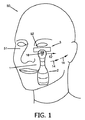
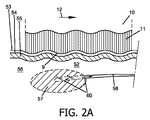
図1は、右の下まぶた51及び左の下まぶた52を持つ、処置されている人物50を示す。図2Aは、該人物の左の下まぶた52を断面で示し、ここで参照番号53、54、55及び56は、該人物の皮膚の、皮膚表面、角質層、表皮、表皮下をそれぞれ示す。表皮下56内には、リンパ液57が存在する。図2Aは更に、図2Bに示されるように人物50の左耳の近くに位置するリンパ節59に接続する、リンパ管58を示す。
FIG. 1 shows a person being treated 50 having a right
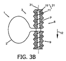
上述した装置1の把持領域及び皮膚処置構造は、それぞれ参照番号2及び3により示され、参照番号8(図3A及び3B参照)は、上述した装置1の皮膚処置領域を示し、把持領域2に対する固定位置である基準点Pが、図3Bに示されるように存在する。更に、図3Aに示されるように、上述した電気エネルギー源及び/又は電気エネルギー源接続部、モータ、運動機構及びコントローラが、それぞれ参照番号4、5、6及び7により示される。
The gripping area and skin treatment structure of the device 1 described above are indicated by
図示された装置1はまた、基準点Pを通る前記突出形状の前記周期的な第1の動きが、皮膚処置領域8における該突出形状の直線運動軌道の一部である、本発明の上述した好適な実施例の一例である。より具体的には、図示された装置1は、本発明の上述した好適な実施例の一例であり、ここで該皮膚処置構造が、第1の回転の長軸のまわりに回転可能であり、該第1の回転の長軸のまわりに螺旋状に形成された少なくとも1つの隆線により形成される外側面を持つ、第1のロールを有し、斯くして、該第1のロールが該第1の回転の長軸のまわりに回転させられたときに、該突出形状を形成する当該隆線、及び当該突出形状が、該皮膚処置領域における前記直線運動軌道を辿る。図3Bにおいて、図示された装置1について、該第1のロール、該第1の回転の長軸、及び該螺旋状に形成された隆線により形成された該突出形状が、それぞれ参照番号21、31及び9により示されている。運動機構6は、第1のロール21に接続され、固定された基準点Pに対する、第1の回転の長軸31のまわりの第1のロール21の回転を引き起こす。
The illustrated device 1 is also the above-described of the present invention, wherein the periodic first movement of the protruding shape through the reference point P is part of the protruding linear motion trajectory in the
図示された装置1はまた、前記突出形状が毛の分布により形成された、本発明の上述した好適な実施例の一例である。図3B及び2Aにおいて、これらの毛が参照番号11により示されている。実際に、図3B及び2Aにおいて示されるように、第1のロール21は、これら毛11とともに螺旋状の核体10を有し、該毛は該核体10に装着される。
The illustrated device 1 is also an example of the above-described preferred embodiment of the present invention in which the protruding shape is formed by hair distribution. In FIGS. 3B and 2A, these hairs are indicated by
図2A及び3Bにおいては、上述した突出形状9の単一の局所的な動き方向が、参照番号12により示されている。図2Aは、皮膚の方向性のマッサージ処置を示し、ここでは、突出形状9の単一の局所的な動き方向12が、皮膚へのもたらし、流体57がリンパ管58に入るようにし、続いてリンパ管58を通る流体57のリンパ排液を引き起こす。図2A及び2Bにおいて、排液方向は参照番号60により示されている。皮膚処置領域8における突出形状9の単一の局所的な動き方向12の結果として、人物50の左耳に向けた、即ち図2Bに示されたリンパ節59の方向に向けた、単一の方向で排液が生じる。
In FIGS. 2A and 3B, the single local movement direction of the protruding
装置1に関する幾つかの適切なデータの例は、以下の通りである。第1のロール21は、約10mmの全体の外径、及び約40mmの長さを持つ(第1の回転の長軸31に沿って測定した値)。図示された例においては、第1のロール21は更に、約10mmのピッチを持つ、1つの螺旋状の隆線を持つ。図示された例においては、当該螺旋状の隆線は、第1のロール21の長さ全体に亘って延在するが、図3Bに示されるように、運動機構6が第1のロール21に接続されるようにし、それによって第1の回転の長軸31のまわりに該第1のロールを回転させるため、第1のロール21の長さのおよそ中間部に中断部分を持つことに、留意されたい。前記周期的な第1の動きの間に、螺旋状の突出形状9が、皮膚処置領域8において装置1の外側へと局所的に突出する、最大突出長は、約3乃至4mmである。典型的な動作状態においては、第1のロール21の回転数は、約1Hzである。前記ピッチ及び該回転数から、前記単一の局所的な動き方向12における基準点Pを通る突出形状9の局所的な動きは、約10mm/秒の速度で生じることが導出される。この場合には、第1のロール21は1つだけの螺旋状の隆線を持つため、上述した基準点Pを通る突出形状9の上述した周期的な第1の動きは、基準点Pにおいて、上述した第1のロール21の回転数、即ち約1Hzに等しい周波数で生じる。該第1のロールがn個の等間隔の螺旋状の隆線(複数ブレードのスクリュープロペラと同様に)を持つ場合には、上述した基準点Pを通る突出形状9の周期的な第1の動きは、基準点Pにおいて、第1のロール21の回転数のn倍のファクタである周波数で生じることとなることに、留意されたい。
Some suitable data examples for the device 1 are as follows. The
図1に示された矢印14は、処置している人物が、所望される場合に、処置されている人物50の左の下まぶた52から左耳の近くの節59に向けて装置1を追加的に動かし得る方向を示し、従って、該人物の皮膚に対する追加的な動き14、即ち、該人物の皮膚に対する単一の局所的な動き方向12において、既に説明されたように、突出形状9の局所的な動きに加えた動きを含む、方向を示す。
The
図示された装置1はまた、該下まぶた処置装置が更に、該装置における又は該装置内の圧力を感知及び/又は測定するよう構成された圧力センサを有し、該感知及び/又は測定された圧力は、前記突出形状と、該突出形状が該装置の動作の間に圧力をかける外部のオブジェクトと、の間に生じる圧力を示す、本発明の上述した好適な実施例の一例である。図3Aにおいては、当該圧力センサは、参照番号15により示される。
The illustrated device 1 also includes a pressure sensor, wherein the lower eyelid treatment device is further configured to sense and / or measure pressure in or within the device, the sensed and / or measured Pressure is an example of the above-described preferred embodiment of the present invention that shows the pressure generated between the protruding shape and an external object that the protruding shape applies pressure during operation of the device. In FIG. 3A, the pressure sensor is indicated by
図示された装置1はまた、該下まぶた処置装置が更に、該装置における又は該装置内の速度を感知及び/又は測定するよう構成された速度センサを有し、該感知及び/又は測定された速度は、前記突出形状と、該突出形状が該装置の動作の間に圧力をかける外部のオブジェクトと、の間に生じる相対速度を示す、本発明の上述した好適な実施例の一例である。図3Aにおいては、当該速度センサは、参照番号16により示される。
The illustrated device 1 also includes a velocity sensor configured to sense and / or measure the velocity in or within the device, the lower eyelid treatment device, wherein the sensed and / or measured Velocity is an example of the above-described preferred embodiment of the present invention showing the relative velocity that occurs between the protruding shape and an external object that the protruding shape applies pressure during operation of the device. In FIG. 3A, the speed sensor is indicated by
図3Aは更に、該装置が、オン/オフボタン、選択ボタン、視覚的ディスプレイ等のような種々の要素を有しても良い、ユーザインタフェース18を有することを示している。例えば、該ユーザインタフェースは、図1及び3Bに示された突出形状の局所的な動き方向12(図1における左の下まぶた52を処置するため)と、図1における右の下まぶた51を処置するための局所的な動き方向12とは反対の局所的な動き方向と、の間をユーザが交番させることを可能とする、第1のロール21の回転の方向を変更するためのスイッチを有しても良い。
FIG. 3A further shows that the device has a
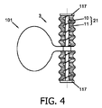
ここで、本発明による下まぶた処置装置の上述した第2の実施例を示す、図4への参照が為される。図4の当該装置101は、皮膚処置構造が更に、前記周期的な第1の動きの間に、前記突出形状が皮膚処置領域において該装置の外側へと局所的に突出する最大突出長を設定するスペーサを更に有する、本発明の上述した好適な実施例の一例である。図4の例においては、該スペーサは、それぞれが第1のロール21の2つの長手方向端部に横断的に装着された、2つの円形ディスク117により形成される。図示された例においては、2つの円形ディスク117は、第1のロール21から取り外し可能である。
Reference is now made to FIG. 4, which shows the above-described second embodiment of the lower eyelid treatment device according to the present invention. The
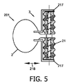
ここで、本発明による下まぶた処置装置の上述した第3の実施例を示す、図5への参照が為される。図5の当該装置201は、皮膚処置構造が更に、前記周期的な第1の動きの間に、前記突出形状が皮膚処置領域において該装置の外側へと局所的に突出する最大突出長を設定するスペーサを更に有する、本発明の上述した好適な実施例の一例である。図5の例においては、該スペーサは、筐体要素217により形成される。図示された例においては、筐体要素217の位置は、図示された方向218において、第1のロール21を含む該装置の他の部分に対して異なる固定位置へと調節可能であり、これにより、当該最大突出長の種々の値をユーザが設定することを可能とする。
Reference is now made to FIG. 5, which shows the above-described third embodiment of the lower eyelid treatment device according to the present invention. The
ここで、本発明による下まぶた処置装置の上述した第4の実施例を示す、図6A及び6Bへの参照が為される。図6A及び6Bの装置301は、基準点Pを通る前記突出形状の前記周期的な第1の動きが、皮膚処置領域における突出形状の曲線運動軌道の一部である、本発明の上述した好適な実施例の一例である。より詳細には、図6A及び6Bの装置301は、該皮膚処置構造が第2のロールを有し、第2の回転の長軸のまわりに回転可能であり、前記第2の回転の長軸に平行な隆線方向を持つ少なくとも1本の隆線により形成された外側面を持つ、第2のロールを有し、前記隆線が前記突出形状を形成し、従って、前記第2のロールが、前記第2の回転の長軸のまわりに回転させられているときに、前記突出形状が、前記皮膚処置領域における前記曲線運動軌道を辿り、前記曲線運動軌道は、前記第2の回転のまわりに延在する、本発明の上述した好適な実施例の一例である。
Reference is now made to FIGS. 6A and 6B showing the above-described fourth embodiment of the lower eyelid treatment device according to the present invention. 6A and 6B, the preferred embodiment of the present invention wherein the periodic first movement of the protruding shape through the reference point P is part of a protruding curved motion trajectory in the skin treatment region. This is an example of an embodiment. More specifically, the
図6A及び6Bにおいては、図示された装置301について、該第2のロール、該第2の回転の長軸、及び該突出形状が、それぞれ参照番号22、32及び9により示されている。図6Bに示された、処置領域8における基準点Pは、把持領域2に対して固定位置である。運動機構6は第2のロール22に接続され、固定基準点Pに対して第2の回転の長軸32のまわりに該第2のロール22を回転させる。
6A and 6B, for the
図示された装置301はまた、突出形状9が毛の分布により形成される、本発明の上述した好適な実施例の一例である。図6A及び6Bにおいては、これらの毛は参照番号41により示される。実際には、図6A及び6Bにおいて示されるように、第2のロール22は、螺旋状の核体40に装着されたこれらの毛41に加え、螺旋状の核体40を有する。図6Bにおいて、第2のロール22は、星型の形状の外観を持ち、斯くして複数の等間隔の突出形状9を形成する。従って、基準点Pを通る前記突出形状9の上述した周期的な第1の動きは、図6Bのものと同様の断面図に含まれる突出形状9の数により乗算された、第2の回転の長軸32のまわりの第2のロール22の回転運動の回転数に等しい周波数で、基準点Pにおいて生じる。本実施例においては、基準点Pを通る各突出形状9の前記周期的な第1の動きは、基準点Pにおける単一の局所的な動き方向12における基準点Pを通る突出形状9の局所的な動きであり、該動きは、回転する第2のロール22の一部として基準点Pにおける突出形状9の局所的な接線方向の動きに対応し、回転する第2のロール22の一部として基準点Pにおける突出形状9の局所的な接線方向の速度に等しい基準点Pにおける速度を持つ。
The illustrated
図示された装置301はまた、皮膚処置構造が更に、前記周期的な第1の動きの間に、前記突出形状が、皮膚処置領域において該装置の外側へと局所的に突出する最大突出長を設定するスペーサを有する、本発明の上述した好適な実施例の一例である。図6A及び6Bにおいては、該スペーサは、それぞれが第2のロール22の2つの長手方向端部に横断的に装着された、2つの円形のディスク317により形成される。図示された実施例においては、2つの円形のディスク317は、第2のロール22から取り外し可能である。当該第4の実施例と関連して、前記最大突出長の種々の値をユーザが設定することを可能とするための、該装置の他の部分に対する種々の固定位置へと調節可能な、選択可能なスペーサも可能である。
The illustrated
本発明は、以上の説明及び図面において詳細に記載され説明されたが、斯かる記載及び説明は例示的なもの及び/又は説明的なものであって、限定的なものではないとみなされるべきであり、本発明は開示された実施例に限定されるものではない。 While the invention has been described and illustrated in detail in the foregoing description and drawings, such description and description are to be considered illustrative and / or illustrative and not restrictive. The invention is not limited to the disclosed embodiments.
例えば、図示された実施例においては、突出形状9は、毛11の分布により形成されている。しかしながら、本発明によれば、斯かる毛の分布の代わりに、突出形状を形成する他の種々の種類の構造を利用することも可能である。例えば、図示された螺旋状の第1のロール21又は図示された星型の第2のロール22において毛を適用する代わりに、該螺旋状の第1のロール又は該星型の第2のロールは、該第1のロール又は第2のロールと一体的に形成された突出形状を備えた、一体的な固体材料として形成されても良い。斯かる材料は、弾力性のある材料(例えばゴム)であっても良いし、又は非弾力性の材料(例えば金属)であっても良い。
For example, in the illustrated embodiment, the protruding
更に、皮膚処置構造の皮膚処置領域が、対応する複数の異なって動く突出形状の対応する複数の異なる局所的な動き方向を持つ、複数の異なる皮膚処置領域を有する、本発明による装置の実施例も可能である。斯かる実施例については、本発明による装置は、人間の皮膚の左の下まぶた領域と右の下まぶた領域との同時の処置に適した、2つの斯かる皮膚処置領域を有しても良いことに、留意されたい。斯かる装置は、2つの皮膚処置領域において同時に引き起こされた2つの局所的な動きの方向が、左の下まぶたから左の耳への排液と、右の下まぶたから右の耳への排液とで、相互に反対となるように動作可能であっても良い。 Furthermore, an embodiment of the device according to the invention, wherein the skin treatment area of the skin treatment structure has a plurality of different skin treatment areas with a corresponding plurality of different local movement directions of a corresponding plurality of differently moving protruding shapes Is also possible. For such an embodiment, the device according to the invention may have two such skin treatment areas suitable for simultaneous treatment of the left and right lower eyelid area of human skin. Please note that. Such a device allows two directions of local movement, simultaneously triggered in two skin treatment areas, to drain from the left lower eyelid to the left ear and from the right lower eyelid to the right ear. The liquid may be operable so as to be opposite to each other.
図面、説明及び添付される請求項を読むことにより、請求される本発明を実施化する当業者によって、開示された実施例に対する他の変形が理解され実行され得る。請求項において、「有する(comprising)」なる語は他の要素又はステップを除外するものではなく、「1つの(a又はan)」なる不定冠詞は複数を除外するものではない。単一のプロセッサ又はその他のユニットが、請求項に列記された幾つかのアイテムの機能を実行しても良い。明確さ及び簡潔な説明の目的のため、ここでは特徴が同一の又は別個の実施例の一部として開示されたが、本発明の範囲は、開示された特徴の全て又は幾つかの組み合わせを持つ実施例を含み得ることは、理解されるであろう。特定の手段が相互に異なる従属請求項に列挙されているという単なる事実は、これら手段の組み合わせが有利に利用されることができないことを示すものではない。請求項におけるいずれの参照記号も、請求の範囲を限定するものとして解釈されるべきではない。 From reading the drawings, description and appended claims, other variations to the disclosed embodiments can be understood and implemented by those skilled in the art in practicing the claimed invention. In the claims, the word “comprising” does not exclude other elements or steps, and the indefinite article “a” or “an” does not exclude a plurality. A single processor or other unit may fulfill the functions of several items recited in the claims. For purposes of clarity and brevity, the features are disclosed herein as part of the same or separate embodiments, but the scope of the invention includes all or some combination of the disclosed features. It will be understood that embodiments may be included. The mere fact that certain measures are recited in mutually different dependent claims does not indicate that a combination of these measured cannot be used to advantage. Any reference signs in the claims should not be construed as limiting the claim.
Claims (16)
前記装置を手で保持するための把持領域を有する外側面と、
前記装置の皮膚処置領域において人間の皮膚を接触するための皮膚接触構造であって、前記皮膚処置領域は、前記把持領域に対して固定された位置に基準点を持ち、前記皮膚処置構造は、前記基準点に対して駆動的に可動である、皮膚処置構造と、
電気エネルギー源及び/又は電気エネルギー供給接続部と、
前記電気エネルギー源及び/又は前記電気エネルギー供給接続部に電気的に接続されたモータと、
前記基準点に対する前記皮膚処置構造の駆動された動きを実現するための、前記皮膚処置構造に接続された運動機構であって、前記モータが前記運動機構に駆動的に接続された、運動機構と、
前記駆動された動きに応じて前記皮膚処置構造を動かすよう、前記運動機構を駆動させるよう、前記モータを少なくとも制御するよう構成されたコントローラと、
を有し、
前記皮膚処置構造の駆動された動きは、前記基準点を通る前記皮膚処置構造の突出形状の周期的な第1の動きを有し、前記皮膚処置領域における前記突出形状は、前記基準点を通る前記記突出形状の前記周期的な第1の動きの間少なくとも一時的に局所的な突出方向に前記装置の外側へと局所的に突出し、前記周期的な第1の動きは、前記突出形状の局所的な突出方向に対して横方向の前記基準点における単一の局所的な動き方向において前記基準点を通る前記突出形状の局所的な動きであり、
前記基準点を通る前記周期的な第1の動きは、0.5Hzと3.0Hzとの間の周波数範囲内の周波数で前記基準点において生じ、
前記基準点を通る前記突出形状の前記局所的な動きは、0.005m/secと0.05m/secとの間の速度範囲内の、前記基準点における速度を持つ、下まぶた処置装置。 A lower eyelid treatment device, the device comprising:
An outer surface having a gripping area for holding the device by hand;
A skin contact structure for contacting human skin in the skin treatment area of the device, the skin treatment area having a reference point at a fixed position relative to the gripping area, the skin treatment structure comprising: A skin treatment structure that is drivably movable relative to the reference point;
An electrical energy source and / or an electrical energy supply connection;
A motor electrically connected to the electrical energy source and / or the electrical energy supply connection;
An exercise mechanism connected to the skin treatment structure for realizing a driven movement of the skin treatment structure relative to the reference point, wherein the motor is drivingly connected to the exercise mechanism; ,
A controller configured to at least control the motor to drive the motion mechanism to move the skin treatment structure in response to the driven movement;
Have
The driven movement of the skin treatment structure has a periodic first movement of the protruding shape of the skin treatment structure through the reference point, and the protruding shape in the skin treatment region passes through the reference point. During the periodic first movement of the protruding shape, the protrusion protrudes locally at least temporarily in the local protruding direction to the outside of the device, the periodic first movement of the protruding shape A local movement of the protruding shape through the reference point in a single local movement direction at the reference point transverse to the local protruding direction;
The periodic first movement through the reference point occurs at the reference point at a frequency within a frequency range between 0.5 Hz and 3.0 Hz;
The lower eyelid treatment device, wherein the local movement of the protruding shape through the reference point has a velocity at the reference point within a velocity range between 0.005 m / sec and 0.05 m / sec.
Applications Claiming Priority (3)
| Application Number | Priority Date | Filing Date | Title |
|---|---|---|---|
| EP14160864 | 2014-03-20 | ||
| EP14160864.6 | 2014-03-20 | ||
| PCT/EP2015/051773 WO2015139869A1 (en) | 2014-03-20 | 2015-01-29 | Lower eyelid treatment |
Publications (2)
| Publication Number | Publication Date |
|---|---|
| JP2017508539A true JP2017508539A (en) | 2017-03-30 |
| JP2017508539A5 JP2017508539A5 (en) | 2018-02-22 |
Family
ID=50342214
Family Applications (1)
| Application Number | Title | Priority Date | Filing Date |
|---|---|---|---|
| JP2016558129A Withdrawn JP2017508539A (en) | 2014-03-20 | 2015-01-29 | Lower eyelid treatment |
Country Status (6)
| Country | Link |
|---|---|
| US (1) | US20170119618A1 (en) |
| EP (1) | EP3119371A1 (en) |
| JP (1) | JP2017508539A (en) |
| CN (1) | CN106102685A (en) |
| RU (1) | RU2016141069A (en) |
| WO (1) | WO2015139869A1 (en) |
Cited By (1)
| Publication number | Priority date | Publication date | Assignee | Title |
|---|---|---|---|---|
| JP2021058610A (en) * | 2016-06-30 | 2021-04-15 | ブラウン ゲーエムベーハー | Epilation device measuring contact force and comprising a feedback unit |
Families Citing this family (5)
| Publication number | Priority date | Publication date | Assignee | Title |
|---|---|---|---|---|
| SE540680C2 (en) * | 2016-06-20 | 2018-10-09 | Goodsomnia Ab | Device for massaging muscles in oral cavity |
| USD830567S1 (en) | 2017-02-01 | 2018-10-09 | Ashley Ophthalmics, LLC | Meibomian gland expression device |
| US11000446B2 (en) | 2017-02-24 | 2021-05-11 | Rekick Massage Inc. | Massage tool |
| CN107981965B (en) * | 2017-11-17 | 2019-12-06 | 上海长海医院 | Eyelid massager |
| US20220047449A1 (en) * | 2020-08-16 | 2022-02-17 | Aizhong Zhang | Device and method for dry eye treatment |
Family Cites Families (6)
| Publication number | Priority date | Publication date | Assignee | Title |
|---|---|---|---|---|
| DE4410912A1 (en) * | 1994-03-29 | 1995-10-05 | Gerhard Arnold | Massager |
| FR2903584B1 (en) * | 2006-07-12 | 2009-02-13 | Alcan Packaging Beauty Serv | ROTARY APPLICATOR OF A COSMETIC PRODUCT. |
| GB0910930D0 (en) * | 2009-06-24 | 2009-08-05 | Innovative Treat Solutions Ltd | Improved massage apparatus and method of use |
| FR2947723B1 (en) * | 2009-07-07 | 2013-04-26 | Oreal | MASSAGE DEVICE. |
| US8491508B2 (en) * | 2010-09-15 | 2013-07-23 | Walton F. Smith | Device and method for stimulating the meibomian glands of the eyelid |
| CN203169553U (en) * | 2013-03-21 | 2013-09-04 | 卢克衍 | Face care device |
-
2015
- 2015-01-29 RU RU2016141069A patent/RU2016141069A/en not_active Application Discontinuation
- 2015-01-29 CN CN201580014705.1A patent/CN106102685A/en active Pending
- 2015-01-29 WO PCT/EP2015/051773 patent/WO2015139869A1/en active Application Filing
- 2015-01-29 JP JP2016558129A patent/JP2017508539A/en not_active Withdrawn
- 2015-01-29 US US15/118,146 patent/US20170119618A1/en not_active Abandoned
- 2015-01-29 EP EP15702443.1A patent/EP3119371A1/en not_active Withdrawn
Cited By (2)
| Publication number | Priority date | Publication date | Assignee | Title |
|---|---|---|---|---|
| JP2021058610A (en) * | 2016-06-30 | 2021-04-15 | ブラウン ゲーエムベーハー | Epilation device measuring contact force and comprising a feedback unit |
| JP7235713B2 (en) | 2016-06-30 | 2023-03-08 | ブラウン ゲーエムベーハー | Epilation device measuring contact force and equipped with feedback unit |
Also Published As
| Publication number | Publication date |
|---|---|
| RU2016141069A (en) | 2018-04-20 |
| EP3119371A1 (en) | 2017-01-25 |
| US20170119618A1 (en) | 2017-05-04 |
| RU2016141069A3 (en) | 2018-09-21 |
| WO2015139869A1 (en) | 2015-09-24 |
| CN106102685A (en) | 2016-11-09 |
Similar Documents
| Publication | Publication Date | Title |
|---|---|---|
| JP2017508539A (en) | Lower eyelid treatment | |
| JP6324382B2 (en) | Skin treatment apparatus and method | |
| EP3082576B1 (en) | Method for treating the skin and device | |
| US10105280B2 (en) | Massaging device | |
| JP5511606B2 (en) | Beauty massager | |
| RU2692271C2 (en) | Skin care device | |
| US20130012848A1 (en) | Massage Device | |
| US20100292723A1 (en) | Disk needle roller | |
| WO1997006767A1 (en) | Massager | |
| JP5579710B2 (en) | Epilator with massage roller | |
| JP2017518842A (en) | Body care device | |
| US11744767B2 (en) | Exfoliating head with rolling elements | |
| JP2017508539A5 (en) | ||
| JP2011125514A (en) | Massage machine | |
| JP2016120107A (en) | Massage device | |
| KR102253412B1 (en) | Handpiece for high-frequency therapy | |
| KR20010008111A (en) | Auto-massage apparatus of impact | |
| KR200247514Y1 (en) | Free rolling facial massager | |
| JP2023522019A (en) | skin treatment system | |
| KR20120042248A (en) | Face massaging devices | |
| EP3435949B1 (en) | Massaging device | |
| JPH08196645A (en) | Electrode for low frequency treatment apparatus and beauty culture apparatus | |
| JP6617958B2 (en) | Massager that polishes the body contact area | |
| JP2023002905A (en) | massage device | |
| JP2012254261A (en) | Method and implement for stimulating the skin |
Legal Events
| Date | Code | Title | Description |
|---|---|---|---|
| RD04 | Notification of resignation of power of attorney |
Free format text: JAPANESE INTERMEDIATE CODE: A7424 Effective date: 20170214 |
|
| A521 | Request for written amendment filed |
Free format text: JAPANESE INTERMEDIATE CODE: A523 Effective date: 20180110 |
|
| A621 | Written request for application examination |
Free format text: JAPANESE INTERMEDIATE CODE: A621 Effective date: 20180110 |
|
| A761 | Written withdrawal of application |
Free format text: JAPANESE INTERMEDIATE CODE: A761 Effective date: 20180611 |