JP2016120107A - Massage device - Google Patents
Massage device Download PDFInfo
- Publication number
- JP2016120107A JP2016120107A JP2014262354A JP2014262354A JP2016120107A JP 2016120107 A JP2016120107 A JP 2016120107A JP 2014262354 A JP2014262354 A JP 2014262354A JP 2014262354 A JP2014262354 A JP 2014262354A JP 2016120107 A JP2016120107 A JP 2016120107A
- Authority
- JP
- Japan
- Prior art keywords
- massage
- electric
- massage head
- massage device
- head
- Prior art date
- Legal status (The legal status is an assumption and is not a legal conclusion. Google has not performed a legal analysis and makes no representation as to the accuracy of the status listed.)
- Pending
Links
Images


Landscapes
- Percussion Or Vibration Massage (AREA)
- Massaging Devices (AREA)
Abstract
Description
本発明は、マッサージ装置、特に皮膚及び筋肉を処置するための身体に適用される電動マッサージ装置に関する。アタッチメントが顔面マッサージにおける使用のために主に意図されるが、身体の他の部分を処置するために利用されても良い。 The present invention relates to a massage device, and more particularly to an electric massage device applied to a body for treating skin and muscles. Attachments are primarily intended for use in facial massage, but may be utilized to treat other parts of the body.
日本の伝統的な手によるマッサージ手法には、軽擦法(effleurage)、叩打法(tapotement)及び揉捏法(petrissage)が含まれる。軽擦法は、皮膚の上を軽くリズミカルに滑らせる動きであり、エラスチン及びコラーゲン繊維に作用することによって皮膚の表面を緩ませること、及び圧力が増大させられる場合には筋肉とかみ合って乳酸及び尿酸を解放させることを目的とする。叩打法は、タッピング(tapping)する動き又はリズミカルに打つことであり、皮膚の表面を刺激して、筋肉を緩ませ、感覚神経受容体を刺激して神経反応を促進することを目的とする。揉捏法は、こねるタイプ、絞るタイプ及び皮膚を回すタイプの動きによって、下にある筋肉を圧縮する、より深い及び高い圧力のマッサージである。 Traditional Japanese hand massage techniques include effleurage, tapotement and petrissage. The light rub is a light and rhythmic movement over the skin that loosens the surface of the skin by acting on elastin and collagen fibers, and when pressure is increased it engages the muscles and lactic acid and The purpose is to release uric acid. The tapping method is tapping or rhythmically tapping, and aims to stimulate the surface of the skin, relax muscles, stimulate sensory nerve receptors and promote neural responses. Acupuncture is a deeper and higher pressure massage that compresses the underlying muscle by kneading, squeezing and turning the skin.
以上に説明したマッサージ手法を手によって実行する場合の問題点は、これら手法は低速で一定しておらず、効果的に為されるには一般に訓練された専門家によって実行される必要がある点である。多くの電動型のハンドヘルド型自己マッサージ装置及びアタッチメントが存在するが、以上に説明されたマッサージ手法を模倣しないか、するとしても適切に模倣しない。しかしながら、電動マッサージ装置において専門のマッサージ師によって一般に利用される以上に説明された手法を再現することによって、増大される血流、リラクセーション、痛みの緩和、増大されたリンパ液の流れ、向上させられた神経刺激、皮膚の引き締め及び活性化を含む、多くの有益な効果が得られる。またユーザは、幸福感といった、より一般的な感覚をもたらされ得る。更に、マッサージ装置は、人間の手では実現できない動きを生成することができ、従ってより効果的で効率的なマッサージを提供し得る。 The problem with performing the massage techniques described above by hand is that they are not constant at low speed and generally need to be performed by a trained professional to be effective. It is. There are many electric handheld self-massage devices and attachments, but they do not mimic or even properly imitate the massage techniques described above. However, by reproducing the techniques described above beyond those commonly used by professional masseurs in electric massage devices, increased blood flow, relaxation, pain relief, increased lymph flow, improved Many beneficial effects are obtained, including nerve stimulation, skin tightening and activation. The user can also be given a more general sense of happiness. In addition, the massage device can generate movements that cannot be achieved with human hands, thus providing a more effective and efficient massage.
本発明の目的は、上述した問題点を著しく軽減又は克服する、電動マッサージ装置を提供することにある。 An object of the present invention is to provide an electric massage device that significantly reduces or overcomes the above-mentioned problems.
本発明によれば、回転軸を持つ駆動シャフトと、皮膚係合面を備えたマッサージヘッドと、を有する電動マッサージ装置であって、前記マッサージヘッドが、前記軸のまわりの回転と、それと同時の前記軸に沿った方向における振動と、のために前記駆動シャフトに装着可能である、電動マッサージ装置が提供される。 According to the present invention, there is provided an electric massage device having a drive shaft having a rotation axis and a massage head having a skin engaging surface, wherein the massage head is rotated around the axis and simultaneously with the rotation. An electric massage device is provided that is attachable to the drive shaft for vibration in a direction along the axis.
皮膚への方向における軸に沿った方向において振動し、同時に該軸のまわりに回転するマッサージヘッドを持つ電動マッサージ装置を提供することによって、軽擦法及び叩打法のような既知の日本のマッサージ手法を非常に模倣するマッサージ効果が達成される。それ故、マッサージを受ける人は、これがなければ専門技術及び経験の欠如によって実現できないであろう、快適で刺激的な体験を得る。また、例えば電動装置は毎秒750回ものタッピング動作を実現でき、電動マッサージ装置の使用によって得られる動きは、手動では、即ち手のみを使う場合では、実現することができないものであることも認識されるであろう。 Known Japanese massage techniques, such as light rub and tapping, by providing an electric massage device with a massage head that vibrates in a direction along the axis in the direction to the skin and simultaneously rotates around the axis A massage effect that mimics the skin is achieved. Therefore, the person receiving the massage gets a comfortable and stimulating experience that would otherwise not be possible due to lack of expertise and experience. In addition, for example, the electric device can realize tapping operation as many as 750 times per second, and it is recognized that the movement obtained by using the electric massage device cannot be realized manually, that is, when only the hand is used. It will be.
好適な実施例においては、前記マッサージヘッドは、中央ハブと複数のマッサージ要素とを有し、各前記マッサージ要素は、前記中央ハブから径方向に離隔され、前記軸のまわりの円周方向に互いから離隔される。 In a preferred embodiment, the massage head has a central hub and a plurality of massage elements, each massage element being radially spaced from the central hub and mutually circumferentially around the axis. Separated from.
当該マッサージヘッドの構成は主に、一時的な変形を生成するため皮膚に対してこれら要素が反復的にタッピングする、叩打法タイプのマッサージを提供するのに効果的である。叩打法、即ち軽くタッピングする動きは、皮膚の表面を刺激して、筋肉の表面を緩ませる。また、組織からリンパ節へとリンパ排液を促し、感覚神経受容体を刺激する。これらの動作は、神経応答を活性化する。 The configuration of the massage head is primarily effective in providing a tapping-type massage where these elements are repeatedly tapped against the skin to create a temporary deformation. The tapping method, i.e. the light tapping movement, stimulates the skin surface and loosens the muscle surface. It stimulates lymph drainage from tissues to lymph nodes and stimulates sensory nerve receptors. These actions activate neural responses.
前記マッサージ要素は、前記中央ハブと一体的に形成され、前記マッサージヘッドの全周のまわりに均等に離隔された、複数の花弁状部を有しても良い。 The massage element may have a plurality of petals that are formed integrally with the central hub and are evenly spaced around the entire circumference of the massage head.
前記花弁状部は均等に離隔されているため、連続的で周期的な動きが生成される。 Since the petals are evenly spaced, a continuous and periodic movement is generated.
理想的には、6乃至17枚の花弁状部があっても良く、花弁状部間の間隔は6mmより大きく23mmより小さくても良い。該間隔距離は、皮膚に対して一時的な変形を生成する触覚誘因に対する生理的な神経応答に基づいて選択される。6mmの間隔が、2つの別個の触覚刺激を人間が知覚する最小距離であることが見出されている。 Ideally, there may be 6 to 17 petals, and the spacing between petals may be greater than 6 mm and less than 23 mm. The spacing distance is selected based on a physiological neural response to a tactile trigger that creates a temporary deformation to the skin. A spacing of 6 mm has been found to be the minimum distance that a human can perceive two separate tactile stimuli.
前記花弁状部のサイズは、皮膚に対する該花弁状部のタッピングが皮膚に対する指のタッピングを模倣するよう、人間の指の大きさに関連付けられる。 The petal size is related to the size of a human finger so that the tapping of the petal on the skin mimics the finger tapping on the skin.
各花弁状部は好適には、3mm乃至8mmの距離だけ、前記ハブから径方向に延在する。 Each petal preferably extends radially from the hub by a distance of 3 mm to 8 mm.
3mm乃至8mmの距離は、マッサージ効果を最大限とし、同時にユーザに対して痛みを引き起こすことを回避する、最適な距離を提供することが見出されている。当該距離は、感覚系を刺激するために十分に大きな皮膚の変形に帰着することが示されている。 It has been found that a distance of 3 mm to 8 mm provides an optimal distance that maximizes the massage effect and at the same time avoids causing pain to the user. This distance has been shown to result in skin deformations large enough to stimulate the sensory system.
前記花弁状部の先端は好適には8mm乃至10mmの半径で湾曲させられ、8mm乃至15mmだけ軸方向に延在しても良い。 The tip of the petal-like part is preferably curved with a radius of 8 mm to 10 mm and may extend in the axial direction by 8 mm to 15 mm.
該湾曲半径は、皮膚への食い込み若しくは皮膚の切断又は痛みを引き起こすことなく、皮膚を軽くタッピングすることをもたらす。該花弁状部の軸方向の延在は、人間の指のサイズを粗く模倣するために選択される。 The curvature radius results in light tapping of the skin without causing bites into the skin or cutting or hurting the skin. The axial extension of the petals is selected to roughly mimic the size of a human finger.
別の実施例においては、前記中央ハブは、前記花弁状部を越えて軸方向に突出する面を持つ。 In another embodiment, the central hub has a surface that projects axially beyond the petals.
前記花弁状部を越えて突出する面を前記中央ハブに備えることにより、該マッサージ装置は、該装置が保持された方向に依存する種々のタイプのマッサージ効果のために使用されることができる。特に、前記花弁状部が皮膚に接触するように該装置が保持されている場合には、叩打法型のマッサージ効果が得られ、前記花弁状部ではなく前記中央ハブが皮膚に接触するように該装置が保持されている場合には、軽擦法のような異なるマッサージ効果が実現され得る。 By providing the central hub with a surface protruding beyond the petals, the massage device can be used for various types of massage effects depending on the direction in which the device is held. In particular, when the device is held so that the petal-shaped part contacts the skin, a tapping-type massage effect is obtained, so that the central hub, not the petal-shaped part, contacts the skin. If the device is held, different massage effects such as a light rub can be realized.
好適には、複数のスポークが中央ハブから延在し、自由に回転可能な要素が各スポークに装着される。該自由に回転可能な要素は、球形の又は一部が球形の球であっても良い。 Preferably, a plurality of spokes extend from the central hub and a freely rotatable element is attached to each spoke. The freely rotatable element may be spherical or partly spherical.
当該マッサージヘッドの構成は、手を用いては実現されない態様で動き、球形の又は一部が球形の球がこれらの間の皮膚を押圧し挟んで、より深い層に達する皮膚に対するこねる効果をもたらす。 The configuration of the massage head moves in a manner that is not realized with the hand, and has the effect of kneading the skin reaching a deeper layer, with a spherical or partly spherical ball pressing against the skin between them .
別の実施例においては、前記マッサージヘッドは基部板を有し、前記中央ハブは、前記基部板の中央から起立する一体型の第1の突出部を有し、前記マッサージ要素は、前記第1の突出部の周囲の、前記第1の突出部からは離隔された、前記基部板の周囲領域から起立した複数の一体型の第2の突出部を有する。 In another embodiment, the massage head has a base plate, the central hub has an integrated first protrusion that stands up from the center of the base plate, and the massage element has the first plate. And a plurality of integral second protrusions standing from the peripheral area of the base plate and spaced from the first protrusion.
当該マッサージヘッドの構成は、皮膚の変形及び伸長を引き起こす。特に、動く第2の突出部と中央の突出部との間で皮膚が伸長される。 The configuration of the massage head causes skin deformation and elongation. In particular, the skin is stretched between the moving second protrusion and the central protrusion.
本発明のいずれかの実施例によれば、該電動マッサージ装置は、第2の所定の時間の間、第2の回転方向に前記マッサージヘッドを回転させる前に、所定の時間の間、第1の回転方向に前記マッサージヘッドを回転させるように構成されたコントローラを有する。 According to any embodiment of the present invention, the electric massage device has a first predetermined period of time before rotating the massage head in a second rotational direction for a second predetermined period of time. A controller configured to rotate the massage head in the direction of rotation.
制御のレベルを提供することにより、ユーザは、効果的なマッサージが実現されたことを確実にすることができる。特に、該マッサージヘッドを最初に一方向に回転させ、次に別の方向に回転させることにより、ユーザは、該マッサージ装置を顔の一方の側に適用し、次いで回転方向が変わると、該マッサージ装置を顔の他方の側に適用しても良い。 By providing a level of control, the user can ensure that an effective massage has been achieved. In particular, by rotating the massage head first in one direction and then in another direction, the user applies the massage device to one side of the face and then changes the direction of rotation, the massage The device may be applied to the other side of the face.
前記コントローラは、前記マッサージヘッドを前記第1の方向に回転させた後、且つ前記第2の方向に回転させる前に、更なる所定の時間の間だけ、前記マッサージヘッドの回転を防止するように構成されても良い。 The controller prevents the massage head from rotating for a further predetermined time after rotating the massage head in the first direction and before rotating in the second direction. It may be configured.
反対方向の回転の間の短い間だけ前記マッサージヘッドの回転を停止することにより、ユーザは、顔の一方の側面から他方へと変更するための時間を与えられる。この方向の変更は、組織内の流体が顔の中心からリンパ節が位置する顔の側面へと移動させられる、リンパ排液を促す。 By stopping the rotation of the massage head only for a short time during rotation in the opposite direction, the user is given time to change from one side of the face to the other. This change in direction facilitates lymph drainage, where fluid in the tissue is moved from the center of the face to the side of the face where the lymph nodes are located.
該コントローラは好適には、30乃至60Hzの周波数で前記軸に沿って前記マッサージヘッドの振動を制御するように動作可能である。 The controller is preferably operable to control the vibration of the massage head along the axis at a frequency of 30-60 Hz.
ユーザに対する試験の結果、当該周波数は、効果的で快適なマッサージを提供することが分かっており、手動の装置では実現できない周波数である。 Tests for users have shown that the frequency is an effective and comfortable massage that is not possible with a manual device.
本発明のこれらの及び他の態様は、以下に説明される実施例を参照しながら説明され明らかとなるであろう。 These and other aspects of the invention will be apparent from and will be elucidated with reference to the embodiments described hereinafter.
本発明の実施例は、添付図面を参照しながら、単に例として、以下に説明される。 Embodiments of the invention will now be described, by way of example only, with reference to the accompanying drawings.
本発明の実施例は、マッサージ装置であって、該装置により回転させられ、同時に軸方向に振動させられるヘッドを備えたマッサージ装置を提供する。該マッサージヘッドは、該マッサージヘッドが回転及び振動するときに、ユーザの皮膚をマッサージする機能を持ち、それにより上述したような軽擦法、叩打法及び揉捏法といった種々の知られたマッサージ法を再現する。本発明のマッサージ装置は、主に顔及び目のまわりをマッサージするために利用されることは想到されよう。 An embodiment of the present invention provides a massage device comprising a head that is rotated by the device and simultaneously vibrated in the axial direction. The massage head has a function of massaging the user's skin when the massage head rotates and vibrates, thereby various known massage methods such as the light rubbing method, the tapping method and the wrinkle method as described above. To reproduce. It will be conceived that the massage device of the present invention is mainly used for massaging around the face and eyes.
図1を参照すると、本発明の実施例によるマッサージ装置1の一般化された図が示されている。マッサージ装置1は、バッテリ3、モータ4、振動器5及びコントローラ6のような、電力源を含む本体又は筐体2を持つ。これら構成要素はいずれも、前記軸のまわりに時計回り又は反時計回り方向に(即ち図1における矢印X又はYの方向に)おいて回転軸A−Aを持つ駆動シャフト7を駆動的に回転させ、軸方向(矢印Zにより示される)に駆動シャフト7を振動させるため、相互接続されている。マッサージヘッド8は、駆動シャフト7に着脱可能に装着され、皮膚係合面9を持つ。
Referring to FIG. 1, a generalized view of a
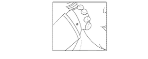
図2は、図1の装置と共に使用されるための、本発明の実施例による第1のマッサージ用アタッチメントを示す。図2から分かるように、皮膚係合面9は完全に滑らかであり、皮膚に対する軽いストローク動作を促進するよう湾曲した形状を持つ。好適には、皮膚係合面9は柔らかく、低摩擦材料から形成される。代替としては、皮膚係合面9は、低摩擦材料によって被覆されても良い。
FIG. 2 shows a first massage attachment according to an embodiment of the invention for use with the device of FIG. As can be seen from FIG. 2, the
該マッサージ装置は、方向A又はBにおいて100乃至180rpmの速度で、図2に示されるマッサージヘッドを回転させ、同時に該マッサージヘッドを、30乃至100Hzの範囲の振動周波数で軸方向Cに振動させるよう構成されても良い。最も好適には、該マッサージヘッドは、158rpmの速度で回転させられる。 The massage device rotates the massage head shown in FIG. 2 at a speed of 100 to 180 rpm in the direction A or B, and simultaneously vibrates the massage head in the axial direction C at a vibration frequency in the range of 30 to 100 Hz. It may be configured. Most preferably, the massage head is rotated at a speed of 158 rpm.
図2のマッサージヘッドは、図1の装置と共に使用される場合に、既知のタイプの軽擦法と呼ばれる手によるマッサージ手法を模倣する。 The massage head of FIG. 2, when used with the apparatus of FIG. 1, mimics a known type of hand massage technique called a light scrub.
図3を参照すると、図1のマッサージ装置1と共に使用されるための、代替のタイプのマッサージヘッド10が示されており、該マッサージヘッド10は、該マッサージヘッドを駆動シャフト7へと接続する中央ハブ11と、該中央ハブ11から径方向に延在し、中央ハブ11の外周全体のまわりに互いから離隔された複数の一体形成された花弁状部12とを持つ。
Referring to FIG. 3, an alternative type of
花弁状部12は、マッサージヘッド10が回転するときに、皮膚に対して一時的な変形をもたらすように意図されたものである。花弁状部12のピーク間の距離は、皮膚に対する指のタッピングに類似するタッピング動作を模倣するため、指のサイズに関連している。花弁状部が等間隔で離隔されているため、連続的で周期的な動きが生成される。
The
図3のマッサージヘッドを用いる場合、ユーザに対する試験の結果、100乃至180rpmの回転速度が好適である。最も好適には、該速度は158rpmである。 When the massage head of FIG. 3 is used, a rotation speed of 100 to 180 rpm is preferable as a result of the test for the user. Most preferably, the speed is 158 rpm.
図3の実施例は8個の花弁状部12を備えたマッサージヘッド10を示しているが、より少ない又はより多い花弁状部12を持つよう、本発明の範囲内でマッサージヘッド10は変更され得る。花弁状部12の好適な数は、6乃至17である。
Although the embodiment of FIG. 3 shows a
好適には、花弁状部間の距離即ちピッチP(図3参照)は23mmより小さく、6mmよりも大きい。6mmよりも短い距離では、感覚反応が知覚されないか又は殆ど知覚されない。 Preferably, the distance between the petals, ie the pitch P (see FIG. 3) is less than 23 mm and greater than 6 mm. At distances shorter than 6 mm, sensory responses are not perceived or hardly perceived.
花弁状部12は、10mmよりも小さい径方向距離Rだけ、中央ハブ11から延在しても良い。花弁状部12の理想的な径方向の延在距離Rは、3乃至8mmであることが分かっている。
The petal-
更に、各花弁状部12は、湾曲した先端13を持つ。該湾曲の好適な曲率半径は、理想的には4及び5mmのオーダーである。
Furthermore, each
好適には、該花弁状部は、8mm乃至15mmの距離だけ軸方向に延在する。 Preferably, the petals extend in the axial direction by a distance of 8 mm to 15 mm.
図3のマッサージヘッド10は、図1に示されたマッサージ装置と共に使用される場合に、既知のタイプの叩打法と呼ばれる手によるマッサージ手法を模倣する。
The
図4(a)は、図2を参照しながら説明されたマッサージヘッドの平滑な皮膚係合面9と、図3を参照しながら説明された花弁状部12を備えたマッサージヘッドとを組み合わせ、単一のマッサージヘッドとした、幾つかの代替のマッサージヘッドを示す。図4(a)に示されたマッサージヘッドのそれぞれから明らかであるように、これらは図3のマッサージヘッド10におけるように中央ハブ11から延在する複数の花弁状部12を持つが、中央ハブ11は軸方向に花弁状部12を超えて延在する隆起した又はドーム型の上側面9も持つ。
FIG. 4 (a) combines the smooth
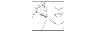
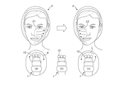
図4(b)を参照すると、図4(a)に示されたマッサージヘッドの1つが装着された、図1によるマッサージ装置1が示されている。マッサージ装置1は、使用された状態で第1の向きにおいて示され、この位置においては、皮膚に対して軽擦法タイプのマッサージ動作をもたらすため、マッサージヘッド14のドーム型の上側面9がユーザの顔に押し付けられる。中央ハブ11の隆起した又は高くされたプロファイルにより、マッサージ装置1が当該第1の向きで使用されているときには、中央ハブ11から径方向に延在する花弁状部12が皮膚と接触しないため、図2を参照しながら以上に説明されたマッサージヘッド8を用いて体感されるものと同様のマッサージ動作が得られることに留意されたい。
Referring to FIG. 4 (b), there is shown the
図4(c)を参照すると、図1のマッサージ装置1が、使用された状態で第2の向きにおいて示され、この位置においては、皮膚に対する叩打法タイプのマッサージ動作をもたらすため、ユーザの顔に対して花弁状部12が押し付けられている。マッサージ装置1が当該第2の向きで使用されているときには、中央ハブ11の高くされた上側面9は皮膚と接触せず、花弁状部12のみが皮膚に接触することに留意されたい。それ故、当該向きにおいては、図3を参照しながら以上に説明されたマッサージヘッド10を用いて体感されるものと同様のマッサージ動作が得られる。
Referring to FIG. 4 (c), the
それ故、本発明の以上に説明された実施例は、異なる構成又は設計ごとにマッサージヘッド14を交換する必要なく、マッサージ装置1の向きに依存して異なるマッサージ手法を生成するように構成されたマッサージヘッド14を持つ、マッサージ装置1を含む。
Therefore, the above described embodiments of the present invention are configured to generate different massage techniques depending on the orientation of the
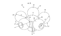
本発明の実施例による別のタイプのマッサージヘッド15が、図5に示される。図示されるように、中央ハブ11が、幾つかのスポーク16(図5には5本が示されている)を備えて形成される。スポーク16は、中央ハブ11から径方向に延在し、互いからは等間隔に離隔されている。各スポーク16には、自由に回転可能な要素17が装着されている。好適には、各要素は平滑で湾曲した皮膚接触面18を持つ。最も好適には、各要素17上の皮膚接触面18は、球形又は部分的に球形であり、それにより要素17はそれぞれが球に類似している。中央ハブ11が30乃至60Hzの範囲内の周波数で回転し、要素17が皮膚に押し付けられると、皮膚Sの表面に対して押し付けられた装置を示す図6に示されるように、要素17の回転が、皮膚が押圧され伸長され摘ままれることを引き起こす。装置1が皮膚表面Sの上を動かされると、矢印Rに示されるように要素17が回転し、Tにより示されるように皮膚Sが隣接する要素17の間で引き上げられ摘ままれることを引き起こす。変形の度合いは、ユーザにより皮膚Sにかけられる力及び皮膚Sの弾性に依存する。中央ハブ11は異なる数のスポーク16を持っていても良く、該中央ハブに装着される球17又は要素の数、及びこれらの直径Dも異なっていても良い。例えば、図5に示される5個の代わりに、3個、4個又は6個の要素17が用いられても良い。該要素は、硬質又は軟質のプラスチック又はエラストマーを含む幾つかの異なる材料からつくられても良く、低摩擦材料からつくられるか又は低摩擦材料によって被覆されていても良い。皮膚の伸長を増大させるため、該要素のサイズ又は直径、該要素の数、駆動シャフトの回転速度、該球の表面摩擦、及び要素17間のピッチPのいずれもが増大させられても良い。
Another type of
上述したマッサージヘッド装置は、図1に示されたマッサージ装置と共に使用された場合に、揉捏法を模倣するマッサージ効果を提供する。 The massage head device described above provides a massage effect that mimics the acupuncture method when used with the massage device shown in FIG.
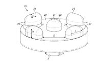
揉捏法型のマッサージ効果を提供する、マッサージヘッドの他の実施例19が、図7に示される。本実施例においては、マッサージヘッド19は、平面の基部面20を持ち、中央ハブが、隆起した内側突出部、ノブ又は突起21であり、マッサージヘッド19の回転軸A−Aと同軸に、基部面の中央から上向きに突出した湾曲した外側面22を備える。幾つかの周縁突出部、ノブ又は突起23が、マッサージヘッド19の周縁のまわりに配置され、基部面20から起立している。周縁突出部23のそれぞれは、内側突出部21から径方向に離隔され、円周方向にも互いから離隔されている。周縁突出部23の寸法は、望ましいマッサージ効果を提供するため変更されても良い。とりわけ、周縁突出部23の外側高さ(図7におけるH)は、4乃至5mmであるべきである。各周縁突出部の幅(W)は、5乃至7mmであるべきである。各周縁突出部間の距離は、6乃至12.5mmであるべきである。各周縁突出部の長さ(L)は、8乃至12mmであるべきである。周縁突出部23の数は、2乃至4であるべきであり、好適には偶数であるべきである。揉捏法は、弾性繊維及びコラーゲン繊維へと及び更には筋肉にまで皮膚表面を操作する、強く深い動きをもたらす。このことは、細胞間液の動きを増進し血流を刺激して、より好適な栄養吸収を可能とし、靭帯及び筋肉の緊張を和らげる。ユーザによりテストされた結果、これらの形状が、皮膚を摘まみ及びこねて最も効果的なマッサージを提供することが見出されている。各周縁突出部23は、基部20から離隔された湾曲した外側面24を持っていても良い。湾曲の度合いは変更されても良く、マッサージヘッド19の回転の速度、及びマッサージヘッド19を形成する材料又はマッサージヘッド19に塗布される被覆の材料の摩擦も変更されても良い。
Another
本発明のいずれの実施例によるマッサージ装置1のコントローラ6も、タイマを含んでも良く、マッサージプログラムに従って該装置の動作を制御しても良い。例えば、図8に示されるように、顔Fが2つの領域z1及びz2に分割させられても良い。装置1を最初にスイッチオンすると、マッサージヘッドは、約90秒のオーダーであっても良い所定の時間の間、矢印Kにより示される第1の方向に回転し、それにより装置1が、顔Fの一方の側、即ち領域z1をマッサージするために用いられても良い。最初の時間が経過すると、コントローラ6が、0.5秒のオーダーであっても良い第2の所定の時間の間、マッサージヘッド15の回転を一時的に停止させる。次いでコントローラ6は、停止する前に、顔の他方の側、即ち領域z2をマッサージするため、更なる所定の時間の間、矢印Lにより示される反対方向にマッサージヘッド15を回転させる。タイマを備えることにより、及びマッサージ装置1を第1の方向Kにおける回転と第2の方向Lにおける回転との間で停止させることにより、プログラムが完了するまで、顔の反対側にマッサージ装置1をいつ当てるべきかをユーザが知ることができる。
The
ユーザの体験をより直観的なものとし、該装置をより操作が容易なものとするため、各マッサージヘッドは、速度及び振動周波数といった、当該マッサージヘッドに関連するマッサージ装置1の設定情報を保存するRFIDタグを含んでも良い。そのため、マッサージ要素が装置1に接続されると、そのことが自動的に検出され、適切な回転及び振動設定が起動される。
In order to make the user experience more intuitive and make the device easier to operate, each massage head stores setting information of the
「有する(comprising)」なる語は他の要素又はステップを除外するものではなく、「1つの(a又はan)」なる不定冠詞は複数を除外するものではないことは、理解されるであろう。特定の手段が相互に異なる従属請求項に列挙されているという単なる事実は、これら手段の組み合わせが有利に利用されることができないことを示すものではない。請求項におけるいずれの参照記号も、請求の範囲を限定するものとして解釈されるべきではない。 It will be understood that the word “comprising” does not exclude other elements or steps, and the indefinite article “a” or “an” does not exclude a plurality. . The mere fact that certain measures are recited in mutually different dependent claims does not indicate that a combination of these measured cannot be used to advantage. Any reference signs in the claims should not be construed as limiting the claim.
添付される請求項は特徴の特定の組み合わせに向けたものであるが、本発明の開示の範囲は、いずれかの請求項において現在請求されているものと同一の発明に関するものであろうとなかろうと、また本発明が軽減するものと同一の技術的課題のいずれか又は全てを軽減するものであろうとなかろうと、明示的若しくは暗黙的にここで開示されたいずれの新規な特徴若しくは特徴の新規な組み合わせ、又はその一般化をも含むことは、理解されるべきである。本出願人はここで、本出願又は本出願から導かれるいずれかの更なる出願の手続きの間に、斯かる特徴及び/又は斯かる特徴の組み合わせに対して、新たな請求項が作成され得ることを注記しておく。
The appended claims are directed to specific combinations of features, but the scope of the disclosure of this invention may or may not be related to the same invention as currently claimed in any claim. And any novel features or features disclosed herein, either explicitly or implicitly, whether or not alleviating any or all of the same technical problems as the invention alleviates. It should be understood that combinations, or generalizations thereof, are also included. The applicant may now create new claims for such features and / or combinations of such features during the procedure of this application or any further application derived from this application. Note that.
Claims (15)
15. The electric massager according to any one of claims 1 to 14, wherein the controller is operable to control vibrations of the massage head along the axis at a frequency of 30 to 60 Hz.
Priority Applications (1)
| Application Number | Priority Date | Filing Date | Title |
|---|---|---|---|
| JP2014262354A JP2016120107A (en) | 2014-12-25 | 2014-12-25 | Massage device |
Applications Claiming Priority (1)
| Application Number | Priority Date | Filing Date | Title |
|---|---|---|---|
| JP2014262354A JP2016120107A (en) | 2014-12-25 | 2014-12-25 | Massage device |
Publications (1)
| Publication Number | Publication Date |
|---|---|
| JP2016120107A true JP2016120107A (en) | 2016-07-07 |
Family
ID=56326793
Family Applications (1)
| Application Number | Title | Priority Date | Filing Date |
|---|---|---|---|
| JP2014262354A Pending JP2016120107A (en) | 2014-12-25 | 2014-12-25 | Massage device |
Country Status (1)
| Country | Link |
|---|---|
| JP (1) | JP2016120107A (en) |
Cited By (2)
| Publication number | Priority date | Publication date | Assignee | Title |
|---|---|---|---|---|
| WO2020105592A1 (en) * | 2018-11-19 | 2020-05-28 | 株式会社資生堂 | Cosmetic device for massage and cosmetic massage method |
| WO2021215409A1 (en) * | 2020-04-20 | 2021-10-28 | 株式会社 資生堂 | Agent for preventing and/or improving photoaging and/or dermal pigmentation, cosmetic method using same, and cosmetic device to be applied in said method |
Citations (3)
| Publication number | Priority date | Publication date | Assignee | Title |
|---|---|---|---|---|
| US2306424A (en) * | 1938-11-16 | 1942-12-29 | William G Betz | Massager |
| JP2003210541A (en) * | 2002-01-19 | 2003-07-29 | Wik Far East Ltd | Massaging attachment for motor-driven type foot care apparatus |
| JP2014018506A (en) * | 2012-07-20 | 2014-02-03 | Ya Man Ltd | Electrically-driven roller massage machine |
-
2014
- 2014-12-25 JP JP2014262354A patent/JP2016120107A/en active Pending
Patent Citations (3)
| Publication number | Priority date | Publication date | Assignee | Title |
|---|---|---|---|---|
| US2306424A (en) * | 1938-11-16 | 1942-12-29 | William G Betz | Massager |
| JP2003210541A (en) * | 2002-01-19 | 2003-07-29 | Wik Far East Ltd | Massaging attachment for motor-driven type foot care apparatus |
| JP2014018506A (en) * | 2012-07-20 | 2014-02-03 | Ya Man Ltd | Electrically-driven roller massage machine |
Cited By (6)
| Publication number | Priority date | Publication date | Assignee | Title |
|---|---|---|---|---|
| WO2020105592A1 (en) * | 2018-11-19 | 2020-05-28 | 株式会社資生堂 | Cosmetic device for massage and cosmetic massage method |
| CN113038917A (en) * | 2018-11-19 | 2021-06-25 | 株式会社资生堂 | Beauty treatment device for massage and massage method for beauty treatment |
| JPWO2020105592A1 (en) * | 2018-11-19 | 2021-09-30 | 株式会社 資生堂 | Beauty equipment for massage, massage method for beauty |
| JP7346448B2 (en) | 2018-11-19 | 2023-09-19 | 株式会社 資生堂 | Beauty equipment and massage equipment |
| WO2021215409A1 (en) * | 2020-04-20 | 2021-10-28 | 株式会社 資生堂 | Agent for preventing and/or improving photoaging and/or dermal pigmentation, cosmetic method using same, and cosmetic device to be applied in said method |
| EP4140544A4 (en) * | 2020-04-20 | 2024-05-29 | Shiseido Company, Ltd. | Agent for preventing and/or improving photoaging and/or dermal pigmentation, cosmetic method using same, and cosmetic device to be applied in said method |
Similar Documents
| Publication | Publication Date | Title |
|---|---|---|
| US10105280B2 (en) | Massaging device | |
| US7384377B2 (en) | Method and apparatus for training facial muscles to reduce wrinkles | |
| CN204428422U (en) | A kind of new micro multifunctional acupoint massage probe | |
| US20170119618A1 (en) | Lower eyelid treatment | |
| KR101346032B1 (en) | Massage machine | |
| KR20240001362U (en) | Mat type massage machine | |
| JP2016120107A (en) | Massage device | |
| KR101747949B1 (en) | Skin Beauty Machine for Massage and Control Method Thereof | |
| KR20180094694A (en) | Massage device based on sound pressure generating structure | |
| KR20120080702A (en) | Massage instrument to apply hula hoop | |
| KR100969346B1 (en) | A hand massage equipment | |
| DE202015104519U1 (en) | massager | |
| KR101460043B1 (en) | An Apparatus for Massage | |
| RU2677788C2 (en) | Massage device | |
| KR200457485Y1 (en) | Potable Apparatus for Massaging skin | |
| KR101288644B1 (en) | Massage apparatus by using vibration | |
| KR100978414B1 (en) | Acupressure instrument for massage | |
| JP3414647B2 (en) | Massage equipment | |
| KR20180122587A (en) | Massage device based on sound pressure generating structure | |
| KR20160089092A (en) | Massage machine | |
| JP6969028B1 (en) | Massage device | |
| RU209065U1 (en) | APPLICATOR MASSAGE MODULE | |
| RU221628U1 (en) | Massager for the muscles of the cheeks, around the lips and lips from the inside of the mouth | |
| RU2766724C1 (en) | Product for aesthetic massage of face, neck, decollete and scalp | |
| KR200373125Y1 (en) | Rotary finger-pressure implement |
Legal Events
| Date | Code | Title | Description |
|---|---|---|---|
| A80 | Written request to apply exceptions to lack of novelty of invention |
Free format text: JAPANESE INTERMEDIATE CODE: A80 Effective date: 20150120 |
|
| RD04 | Notification of resignation of power of attorney |
Free format text: JAPANESE INTERMEDIATE CODE: A7424 Effective date: 20170214 |
|
| A621 | Written request for application examination |
Free format text: JAPANESE INTERMEDIATE CODE: A621 Effective date: 20171211 |
|
| A131 | Notification of reasons for refusal |
Free format text: JAPANESE INTERMEDIATE CODE: A131 Effective date: 20180911 |
|
| A977 | Report on retrieval |
Free format text: JAPANESE INTERMEDIATE CODE: A971007 Effective date: 20180912 |
|
| A601 | Written request for extension of time |
Free format text: JAPANESE INTERMEDIATE CODE: A601 Effective date: 20181203 |
|
| A521 | Request for written amendment filed |
Free format text: JAPANESE INTERMEDIATE CODE: A523 Effective date: 20190225 |
|
| A02 | Decision of refusal |
Free format text: JAPANESE INTERMEDIATE CODE: A02 Effective date: 20190618 |
|
| A521 | Request for written amendment filed |
Free format text: JAPANESE INTERMEDIATE CODE: A523 Effective date: 20191009 |
|
| C60 | Trial request (containing other claim documents, opposition documents) |
Free format text: JAPANESE INTERMEDIATE CODE: C60 Effective date: 20191009 |
|
| A911 | Transfer to examiner for re-examination before appeal (zenchi) |
Free format text: JAPANESE INTERMEDIATE CODE: A911 Effective date: 20191018 |
|
| C21 | Notice of transfer of a case for reconsideration by examiners before appeal proceedings |
Free format text: JAPANESE INTERMEDIATE CODE: C21 Effective date: 20191023 |
|
| A912 | Re-examination (zenchi) completed and case transferred to appeal board |
Free format text: JAPANESE INTERMEDIATE CODE: A912 Effective date: 20191220 |
|
| C211 | Notice of termination of reconsideration by examiners before appeal proceedings |
Free format text: JAPANESE INTERMEDIATE CODE: C211 Effective date: 20191224 |
|
| C22 | Notice of designation (change) of administrative judge |
Free format text: JAPANESE INTERMEDIATE CODE: C22 Effective date: 20200623 |
|
| C22 | Notice of designation (change) of administrative judge |
Free format text: JAPANESE INTERMEDIATE CODE: C22 Effective date: 20200901 |
|
| C13 | Notice of reasons for refusal |
Free format text: JAPANESE INTERMEDIATE CODE: C13 Effective date: 20200908 |
|
| C23 | Notice of termination of proceedings |
Free format text: JAPANESE INTERMEDIATE CODE: C23 Effective date: 20210126 |
|
| C03 | Trial/appeal decision taken |
Free format text: JAPANESE INTERMEDIATE CODE: C03 Effective date: 20210311 |
|
| C30A | Notification sent |
Free format text: JAPANESE INTERMEDIATE CODE: C3012 Effective date: 20210311 |