JP2017507752A - Indwelling body lumen dilator - Google Patents
Indwelling body lumen dilator Download PDFInfo
- Publication number
- JP2017507752A JP2017507752A JP2016557555A JP2016557555A JP2017507752A JP 2017507752 A JP2017507752 A JP 2017507752A JP 2016557555 A JP2016557555 A JP 2016557555A JP 2016557555 A JP2016557555 A JP 2016557555A JP 2017507752 A JP2017507752 A JP 2017507752A
- Authority
- JP
- Japan
- Prior art keywords
- dilator
- body lumen
- structures
- dilator structure
- tissue
- Prior art date
- Legal status (The legal status is an assumption and is not a legal conclusion. Google has not performed a legal analysis and makes no representation as to the accuracy of the status listed.)
- Granted
Links
- 210000002307 prostate Anatomy 0.000 claims abstract description 50
- 210000001519 tissue Anatomy 0.000 claims description 61
- 230000007246 mechanism Effects 0.000 claims description 23
- 238000000034 method Methods 0.000 claims description 22
- 238000004873 anchoring Methods 0.000 claims 1
- 230000002308 calcification Effects 0.000 abstract description 3
- 239000012530 fluid Substances 0.000 abstract description 3
- 238000012423 maintenance Methods 0.000 abstract 1
- 206010046459 urethral obstruction Diseases 0.000 abstract 1
- 210000003708 urethra Anatomy 0.000 description 18
- 206010004446 Benign prostatic hyperplasia Diseases 0.000 description 10
- 208000004403 Prostatic Hyperplasia Diseases 0.000 description 10
- 239000000463 material Substances 0.000 description 10
- 210000002700 urine Anatomy 0.000 description 8
- 229910001000 nickel titanium Inorganic materials 0.000 description 7
- HLXZNVUGXRDIFK-UHFFFAOYSA-N nickel titanium Chemical compound [Ti].[Ti].[Ti].[Ti].[Ti].[Ti].[Ti].[Ti].[Ti].[Ti].[Ti].[Ni].[Ni].[Ni].[Ni].[Ni].[Ni].[Ni].[Ni].[Ni].[Ni].[Ni].[Ni].[Ni].[Ni] HLXZNVUGXRDIFK-UHFFFAOYSA-N 0.000 description 7
- 230000000712 assembly Effects 0.000 description 6
- 238000000429 assembly Methods 0.000 description 6
- 238000001816 cooling Methods 0.000 description 6
- 230000027939 micturition Effects 0.000 description 6
- 238000011282 treatment Methods 0.000 description 6
- 238000012800 visualization Methods 0.000 description 6
- 206010046555 Urinary retention Diseases 0.000 description 5
- 230000010339 dilation Effects 0.000 description 5
- 239000000560 biocompatible material Substances 0.000 description 4
- 239000003124 biologic agent Substances 0.000 description 4
- 230000015572 biosynthetic process Effects 0.000 description 4
- 238000000576 coating method Methods 0.000 description 4
- 238000010438 heat treatment Methods 0.000 description 4
- 238000003384 imaging method Methods 0.000 description 4
- 238000003780 insertion Methods 0.000 description 4
- 230000037431 insertion Effects 0.000 description 4
- 239000004033 plastic Substances 0.000 description 4
- 229920003023 plastic Polymers 0.000 description 4
- ZAHRKKWIAAJSAO-UHFFFAOYSA-N rapamycin Natural products COCC(O)C(=C/C(C)C(=O)CC(OC(=O)C1CCCCN1C(=O)C(=O)C2(O)OC(CC(OC)C(=CC=CC=CC(C)CC(C)C(=O)C)C)CCC2C)C(C)CC3CCC(O)C(C3)OC)C ZAHRKKWIAAJSAO-UHFFFAOYSA-N 0.000 description 4
- 229910001285 shape-memory alloy Inorganic materials 0.000 description 4
- QFJCIRLUMZQUOT-HPLJOQBZSA-N sirolimus Chemical compound C1C[C@@H](O)[C@H](OC)C[C@@H]1C[C@@H](C)[C@H]1OC(=O)[C@@H]2CCCCN2C(=O)C(=O)[C@](O)(O2)[C@H](C)CC[C@H]2C[C@H](OC)/C(C)=C/C=C/C=C/[C@@H](C)C[C@@H](C)C(=O)[C@H](OC)[C@H](O)/C(C)=C/[C@@H](C)C(=O)C1 QFJCIRLUMZQUOT-HPLJOQBZSA-N 0.000 description 4
- 229960002930 sirolimus Drugs 0.000 description 4
- 208000024891 symptom Diseases 0.000 description 4
- 239000002184 metal Substances 0.000 description 3
- 229910052751 metal Inorganic materials 0.000 description 3
- 238000012986 modification Methods 0.000 description 3
- 230000004048 modification Effects 0.000 description 3
- 238000011471 prostatectomy Methods 0.000 description 3
- 239000010935 stainless steel Substances 0.000 description 3
- 229910001220 stainless steel Inorganic materials 0.000 description 3
- 201000002327 urinary tract obstruction Diseases 0.000 description 3
- 239000002677 5-alpha reductase inhibitor Substances 0.000 description 2
- 229930012538 Paclitaxel Natural products 0.000 description 2
- 206010051482 Prostatomegaly Diseases 0.000 description 2
- 210000004204 blood vessel Anatomy 0.000 description 2
- 210000000746 body region Anatomy 0.000 description 2
- 230000036760 body temperature Effects 0.000 description 2
- 230000010261 cell growth Effects 0.000 description 2
- 230000000295 complement effect Effects 0.000 description 2
- 238000002591 computed tomography Methods 0.000 description 2
- 230000008602 contraction Effects 0.000 description 2
- 230000000694 effects Effects 0.000 description 2
- 230000002209 hydrophobic effect Effects 0.000 description 2
- 230000002401 inhibitory effect Effects 0.000 description 2
- 239000007788 liquid Substances 0.000 description 2
- 238000002595 magnetic resonance imaging Methods 0.000 description 2
- 150000002739 metals Chemical class 0.000 description 2
- 229960001592 paclitaxel Drugs 0.000 description 2
- 230000036961 partial effect Effects 0.000 description 2
- 239000002590 phosphodiesterase V inhibitor Substances 0.000 description 2
- 239000005020 polyethylene terephthalate Substances 0.000 description 2
- 229920000642 polymer Polymers 0.000 description 2
- 239000004810 polytetrafluoroethylene Substances 0.000 description 2
- 229920001343 polytetrafluoroethylene Polymers 0.000 description 2
- 229910052710 silicon Inorganic materials 0.000 description 2
- 239000010703 silicon Substances 0.000 description 2
- 210000005070 sphincter Anatomy 0.000 description 2
- 230000003075 superhydrophobic effect Effects 0.000 description 2
- 238000001356 surgical procedure Methods 0.000 description 2
- RCINICONZNJXQF-MZXODVADSA-N taxol Chemical compound O([C@@H]1[C@@]2(C[C@@H](C(C)=C(C2(C)C)[C@H](C([C@]2(C)[C@@H](O)C[C@H]3OC[C@]3([C@H]21)OC(C)=O)=O)OC(=O)C)OC(=O)[C@H](O)[C@@H](NC(=O)C=1C=CC=CC=1)C=1C=CC=CC=1)O)C(=O)C1=CC=CC=C1 RCINICONZNJXQF-MZXODVADSA-N 0.000 description 2
- 230000008467 tissue growth Effects 0.000 description 2
- 238000002604 ultrasonography Methods 0.000 description 2
- 206010002091 Anaesthesia Diseases 0.000 description 1
- 206010005003 Bladder cancer Diseases 0.000 description 1
- 208000018672 Dilatation Diseases 0.000 description 1
- 206010013642 Drooling Diseases 0.000 description 1
- 206010021639 Incontinence Diseases 0.000 description 1
- 206010061218 Inflammation Diseases 0.000 description 1
- 239000004696 Poly ether ether ketone Substances 0.000 description 1
- 239000004642 Polyimide Substances 0.000 description 1
- 206010060862 Prostate cancer Diseases 0.000 description 1
- 208000000236 Prostatic Neoplasms Diseases 0.000 description 1
- 208000001647 Renal Insufficiency Diseases 0.000 description 1
- 206010040047 Sepsis Diseases 0.000 description 1
- 208000008630 Sialorrhea Diseases 0.000 description 1
- 206010065584 Urethral stenosis Diseases 0.000 description 1
- 208000007097 Urinary Bladder Neoplasms Diseases 0.000 description 1
- 238000002679 ablation Methods 0.000 description 1
- 230000004913 activation Effects 0.000 description 1
- 230000037005 anaesthesia Effects 0.000 description 1
- JUPQTSLXMOCDHR-UHFFFAOYSA-N benzene-1,4-diol;bis(4-fluorophenyl)methanone Chemical compound OC1=CC=C(O)C=C1.C1=CC(F)=CC=C1C(=O)C1=CC=C(F)C=C1 JUPQTSLXMOCDHR-UHFFFAOYSA-N 0.000 description 1
- 230000003750 conditioning effect Effects 0.000 description 1
- 230000003247 decreasing effect Effects 0.000 description 1
- 230000002950 deficient Effects 0.000 description 1
- 201000010099 disease Diseases 0.000 description 1
- 208000037265 diseases, disorders, signs and symptoms Diseases 0.000 description 1
- 229940079593 drug Drugs 0.000 description 1
- 239000003814 drug Substances 0.000 description 1
- 206010013990 dysuria Diseases 0.000 description 1
- 230000002996 emotional effect Effects 0.000 description 1
- 210000000981 epithelium Anatomy 0.000 description 1
- 210000001035 gastrointestinal tract Anatomy 0.000 description 1
- 210000004392 genitalia Anatomy 0.000 description 1
- PCHJSUWPFVWCPO-UHFFFAOYSA-N gold Chemical compound [Au] PCHJSUWPFVWCPO-UHFFFAOYSA-N 0.000 description 1
- 239000007943 implant Substances 0.000 description 1
- 238000007373 indentation Methods 0.000 description 1
- 208000015181 infectious disease Diseases 0.000 description 1
- 230000004054 inflammatory process Effects 0.000 description 1
- 238000001802 infusion Methods 0.000 description 1
- 230000007794 irritation Effects 0.000 description 1
- 230000005722 itchiness Effects 0.000 description 1
- 201000006370 kidney failure Diseases 0.000 description 1
- 238000002350 laparotomy Methods 0.000 description 1
- 230000000670 limiting effect Effects 0.000 description 1
- 230000007774 longterm Effects 0.000 description 1
- 230000003211 malignant effect Effects 0.000 description 1
- 238000013508 migration Methods 0.000 description 1
- 230000005012 migration Effects 0.000 description 1
- 210000003205 muscle Anatomy 0.000 description 1
- 206010029446 nocturia Diseases 0.000 description 1
- 230000000414 obstructive effect Effects 0.000 description 1
- 210000003899 penis Anatomy 0.000 description 1
- 230000002093 peripheral effect Effects 0.000 description 1
- 229920002530 polyetherether ketone Polymers 0.000 description 1
- 229920001721 polyimide Polymers 0.000 description 1
- 201000004240 prostatic hypertrophy Diseases 0.000 description 1
- 238000002271 resection Methods 0.000 description 1
- 238000007788 roughening Methods 0.000 description 1
- 230000001568 sexual effect Effects 0.000 description 1
- 238000004513 sizing Methods 0.000 description 1
- 238000011272 standard treatment Methods 0.000 description 1
- 238000002560 therapeutic procedure Methods 0.000 description 1
- 238000000015 thermotherapy Methods 0.000 description 1
- 201000001988 urethral stricture Diseases 0.000 description 1
- 201000005112 urinary bladder cancer Diseases 0.000 description 1
- 210000001635 urinary tract Anatomy 0.000 description 1
Images


Classifications
-
- A—HUMAN NECESSITIES
- A61—MEDICAL OR VETERINARY SCIENCE; HYGIENE
- A61F—FILTERS IMPLANTABLE INTO BLOOD VESSELS; PROSTHESES; DEVICES PROVIDING PATENCY TO, OR PREVENTING COLLAPSING OF, TUBULAR STRUCTURES OF THE BODY, e.g. STENTS; ORTHOPAEDIC, NURSING OR CONTRACEPTIVE DEVICES; FOMENTATION; TREATMENT OR PROTECTION OF EYES OR EARS; BANDAGES, DRESSINGS OR ABSORBENT PADS; FIRST-AID KITS
- A61F2/00—Filters implantable into blood vessels; Prostheses, i.e. artificial substitutes or replacements for parts of the body; Appliances for connecting them with the body; Devices providing patency to, or preventing collapsing of, tubular structures of the body, e.g. stents
- A61F2/82—Devices providing patency to, or preventing collapsing of, tubular structures of the body, e.g. stents
- A61F2/86—Stents in a form characterised by the wire-like elements; Stents in the form characterised by a net-like or mesh-like structure
- A61F2/89—Stents in a form characterised by the wire-like elements; Stents in the form characterised by a net-like or mesh-like structure the wire-like elements comprising two or more adjacent rings flexibly connected by separate members
-
- A—HUMAN NECESSITIES
- A61—MEDICAL OR VETERINARY SCIENCE; HYGIENE
- A61F—FILTERS IMPLANTABLE INTO BLOOD VESSELS; PROSTHESES; DEVICES PROVIDING PATENCY TO, OR PREVENTING COLLAPSING OF, TUBULAR STRUCTURES OF THE BODY, e.g. STENTS; ORTHOPAEDIC, NURSING OR CONTRACEPTIVE DEVICES; FOMENTATION; TREATMENT OR PROTECTION OF EYES OR EARS; BANDAGES, DRESSINGS OR ABSORBENT PADS; FIRST-AID KITS
- A61F2/00—Filters implantable into blood vessels; Prostheses, i.e. artificial substitutes or replacements for parts of the body; Appliances for connecting them with the body; Devices providing patency to, or preventing collapsing of, tubular structures of the body, e.g. stents
- A61F2/02—Prostheses implantable into the body
- A61F2/04—Hollow or tubular parts of organs, e.g. bladders, tracheae, bronchi or bile ducts
-
- A—HUMAN NECESSITIES
- A61—MEDICAL OR VETERINARY SCIENCE; HYGIENE
- A61F—FILTERS IMPLANTABLE INTO BLOOD VESSELS; PROSTHESES; DEVICES PROVIDING PATENCY TO, OR PREVENTING COLLAPSING OF, TUBULAR STRUCTURES OF THE BODY, e.g. STENTS; ORTHOPAEDIC, NURSING OR CONTRACEPTIVE DEVICES; FOMENTATION; TREATMENT OR PROTECTION OF EYES OR EARS; BANDAGES, DRESSINGS OR ABSORBENT PADS; FIRST-AID KITS
- A61F2/00—Filters implantable into blood vessels; Prostheses, i.e. artificial substitutes or replacements for parts of the body; Appliances for connecting them with the body; Devices providing patency to, or preventing collapsing of, tubular structures of the body, e.g. stents
- A61F2/82—Devices providing patency to, or preventing collapsing of, tubular structures of the body, e.g. stents
- A61F2/848—Devices providing patency to, or preventing collapsing of, tubular structures of the body, e.g. stents having means for fixation to the vessel wall, e.g. barbs
-
- A—HUMAN NECESSITIES
- A61—MEDICAL OR VETERINARY SCIENCE; HYGIENE
- A61F—FILTERS IMPLANTABLE INTO BLOOD VESSELS; PROSTHESES; DEVICES PROVIDING PATENCY TO, OR PREVENTING COLLAPSING OF, TUBULAR STRUCTURES OF THE BODY, e.g. STENTS; ORTHOPAEDIC, NURSING OR CONTRACEPTIVE DEVICES; FOMENTATION; TREATMENT OR PROTECTION OF EYES OR EARS; BANDAGES, DRESSINGS OR ABSORBENT PADS; FIRST-AID KITS
- A61F2/00—Filters implantable into blood vessels; Prostheses, i.e. artificial substitutes or replacements for parts of the body; Appliances for connecting them with the body; Devices providing patency to, or preventing collapsing of, tubular structures of the body, e.g. stents
- A61F2/82—Devices providing patency to, or preventing collapsing of, tubular structures of the body, e.g. stents
- A61F2/86—Stents in a form characterised by the wire-like elements; Stents in the form characterised by a net-like or mesh-like structure
-
- A—HUMAN NECESSITIES
- A61—MEDICAL OR VETERINARY SCIENCE; HYGIENE
- A61F—FILTERS IMPLANTABLE INTO BLOOD VESSELS; PROSTHESES; DEVICES PROVIDING PATENCY TO, OR PREVENTING COLLAPSING OF, TUBULAR STRUCTURES OF THE BODY, e.g. STENTS; ORTHOPAEDIC, NURSING OR CONTRACEPTIVE DEVICES; FOMENTATION; TREATMENT OR PROTECTION OF EYES OR EARS; BANDAGES, DRESSINGS OR ABSORBENT PADS; FIRST-AID KITS
- A61F2/00—Filters implantable into blood vessels; Prostheses, i.e. artificial substitutes or replacements for parts of the body; Appliances for connecting them with the body; Devices providing patency to, or preventing collapsing of, tubular structures of the body, e.g. stents
- A61F2/95—Instruments specially adapted for placement or removal of stents or stent-grafts
-
- A—HUMAN NECESSITIES
- A61—MEDICAL OR VETERINARY SCIENCE; HYGIENE
- A61F—FILTERS IMPLANTABLE INTO BLOOD VESSELS; PROSTHESES; DEVICES PROVIDING PATENCY TO, OR PREVENTING COLLAPSING OF, TUBULAR STRUCTURES OF THE BODY, e.g. STENTS; ORTHOPAEDIC, NURSING OR CONTRACEPTIVE DEVICES; FOMENTATION; TREATMENT OR PROTECTION OF EYES OR EARS; BANDAGES, DRESSINGS OR ABSORBENT PADS; FIRST-AID KITS
- A61F2/00—Filters implantable into blood vessels; Prostheses, i.e. artificial substitutes or replacements for parts of the body; Appliances for connecting them with the body; Devices providing patency to, or preventing collapsing of, tubular structures of the body, e.g. stents
- A61F2/02—Prostheses implantable into the body
- A61F2/04—Hollow or tubular parts of organs, e.g. bladders, tracheae, bronchi or bile ducts
- A61F2002/047—Urethrae
-
- A—HUMAN NECESSITIES
- A61—MEDICAL OR VETERINARY SCIENCE; HYGIENE
- A61F—FILTERS IMPLANTABLE INTO BLOOD VESSELS; PROSTHESES; DEVICES PROVIDING PATENCY TO, OR PREVENTING COLLAPSING OF, TUBULAR STRUCTURES OF THE BODY, e.g. STENTS; ORTHOPAEDIC, NURSING OR CONTRACEPTIVE DEVICES; FOMENTATION; TREATMENT OR PROTECTION OF EYES OR EARS; BANDAGES, DRESSINGS OR ABSORBENT PADS; FIRST-AID KITS
- A61F2230/00—Geometry of prostheses classified in groups A61F2/00 - A61F2/26 or A61F2/82 or A61F9/00 or A61F11/00 or subgroups thereof
- A61F2230/0063—Three-dimensional shapes
- A61F2230/0065—Three-dimensional shapes toroidal, e.g. ring-shaped, doughnut-shaped
-
- A—HUMAN NECESSITIES
- A61—MEDICAL OR VETERINARY SCIENCE; HYGIENE
- A61F—FILTERS IMPLANTABLE INTO BLOOD VESSELS; PROSTHESES; DEVICES PROVIDING PATENCY TO, OR PREVENTING COLLAPSING OF, TUBULAR STRUCTURES OF THE BODY, e.g. STENTS; ORTHOPAEDIC, NURSING OR CONTRACEPTIVE DEVICES; FOMENTATION; TREATMENT OR PROTECTION OF EYES OR EARS; BANDAGES, DRESSINGS OR ABSORBENT PADS; FIRST-AID KITS
- A61F2250/00—Special features of prostheses classified in groups A61F2/00 - A61F2/26 or A61F2/82 or A61F9/00 or A61F11/00 or subgroups thereof
- A61F2250/0004—Special features of prostheses classified in groups A61F2/00 - A61F2/26 or A61F2/82 or A61F9/00 or A61F11/00 or subgroups thereof adjustable
- A61F2250/001—Special features of prostheses classified in groups A61F2/00 - A61F2/26 or A61F2/82 or A61F9/00 or A61F11/00 or subgroups thereof adjustable for adjusting a diameter
Landscapes
- Health & Medical Sciences (AREA)
- Engineering & Computer Science (AREA)
- Biomedical Technology (AREA)
- Cardiology (AREA)
- Oral & Maxillofacial Surgery (AREA)
- Transplantation (AREA)
- Heart & Thoracic Surgery (AREA)
- Vascular Medicine (AREA)
- Life Sciences & Earth Sciences (AREA)
- Animal Behavior & Ethology (AREA)
- General Health & Medical Sciences (AREA)
- Public Health (AREA)
- Veterinary Medicine (AREA)
- Gastroenterology & Hepatology (AREA)
- Pulmonology (AREA)
- Surgical Instruments (AREA)
- Prostheses (AREA)
- Media Introduction/Drainage Providing Device (AREA)
Abstract
【課題】尿道閉塞を緩和するため、尿道前立腺部等の体内管腔の維持及び開存性を可能にする留置型体内管腔拡張具を提供する。【解決手段】1つ以上の拡張具は、体内管腔の直径に対して比較的大きな直径を有するため、内腔壁内に陥入されることにより、人工装具が流体露出を回避できるようにし、引いては人工装具の外被又は石灰化を防ぐ。【選択図】図9BIn order to alleviate urethral obstruction, an indwelling body lumen dilator that enables maintenance and patency of a body lumen such as a urethral prostate is provided. One or more dilators have a relatively large diameter relative to the diameter of the body lumen so that the prosthesis can avoid fluid exposure by being invaginated into the lumen wall. Pull to prevent the envelope or calcification of the prosthesis. [Selection] Figure 9B
Description
(関連出願)本願は、2014年3月14日出願の米国仮出願第61/953,212号及び2014年8月11日出願の米国仮出願第62/035,826号の優先権を主張し、各々の内容全体を参照としてここに組み込む。 (Related Applications) This application claims priority from US Provisional Application No. 61 / 953,212 filed on March 14, 2014 and US Provisional Application No. 62 / 035,826 filed on August 11, 2014. The entire contents of each are incorporated herein by reference.
本発明は、体内管腔の開存性を確保する留置型体内管腔拡張具全般に係る。本発明は、特に、良性前立腺過形成等の状態に起因する尿閉を緩和するため、尿道管内で展開してもよい1つ以上の留置型体内管腔拡張具に係る。本明細書に記載の拡張具及び方法は、例えば、血管、消化管、気道、生殖器官、尿道等の解剖学的管腔の拡張が必要なその他の態様において適用してもよい。 The present invention relates generally to an indwelling body lumen dilator that ensures patency of a body lumen. In particular, the present invention relates to one or more indwelling body lumen dilators that may be deployed within the urethral canal to alleviate urinary retention due to conditions such as benign prostatic hyperplasia. The dilators and methods described herein may be applied in other aspects where anatomical lumen expansion is required, such as, for example, blood vessels, gastrointestinal tracts, airways, genital organs, urethra, and the like.
尿閉は、患者が膀胱を空にするのが困難又は不可能である際に発生する。その原因にはいくつかの原因があるが、尿閉は、前立腺がん、膀胱がん、尿路損傷、良性又は悪性の尿道狭窄等の機能的閉塞によっても引き起こされ得るものの、男性にとって最も一般的な原因は良性前立腺過形成(BPH)である。尿閉は、排尿困難、いきみ、尿勢低下、排尿垂れ、残尿感、排尿障害、夜間頻尿、頻尿、及び/又は失禁を経験したことのある患者を悩ませるものである。尿路閉塞が深刻になると、腎不全又は敗血症を含むより深刻な結果を招き得る。 Urinary retention occurs when it is difficult or impossible for the patient to empty the bladder. Although there are several causes, urinary retention is the most common for men, although it can also be caused by functional obstruction such as prostate cancer, bladder cancer, urinary tract damage, benign or malignant urethral stricture A common cause is benign prostatic hyperplasia (BPH). Urinary retention afflicts a patient who has experienced difficulty urinating, itchiness, decreased urination, drooling, residual urination, dysuria, nocturia, frequent urination, and / or incontinence. Severe urinary tract obstruction can have more serious consequences, including renal failure or sepsis.
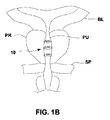
良性前立腺過形成は、前立腺肥大としても知られているが、閉塞性尿閉の最も一般的な原因である。図1Aに示すとおり、くるみ大の前立腺PRが、男性の膀胱出口直下の尿道を包囲し、加齢に伴って肥大することが知られている。膀胱出口は、膀胱頸BNにおいて、前立腺PRを通って伸びる尿道前立腺部PU内に開放するように示されている。尿道前立腺部は、尿道膜性部MU内に伸び、さらに尿道球部BU内に伸びる。陰茎を通って伸びる尿道部分は、その終端部で尿道口UO内に開放する陰茎尿道PUとして示されている。 Benign prostatic hyperplasia, also known as prostatic hypertrophy, is the most common cause of obstructive urinary retention. As shown in FIG. 1A, it is known that a walnut-sized prostate PR surrounds the urethra directly under the bladder outlet of a man and enlarges with age. The bladder outlet is shown to open into the urethral prostate part PU extending through the prostate PR in the bladder neck BN. The urethral prostate part extends into the urethral part MU, and further extends into the urethral bulb BU. The portion of the urethra that extends through the penis is shown as a penile urethra PU that opens into the urethral orifice UO at its end.
前立腺PRは尿道に侵入するため、前立腺PRは膀胱BLからの尿流を妨害し始め、患者に不快感を生じる。BPHは通常、40歳を超える男性に発生し、加齢に伴って有病率が増加し、例えば、50歳を超える男性の50%、80歳を超える男性の90%がBPHを発症していることが組織学的に証明されている。 Since prostate PR enters the urethra, prostate PR begins to obstruct urine flow from bladder BL, causing discomfort to the patient. BPH usually occurs in men over 40 years of age and the prevalence increases with age, for example, 50% of men over 50 years old and 90% of men over 80 years old develop BPH. Histologically proven to be.
薬剤抵抗性の中度から重度のBPHに対するゴールドスタンダードな治療は、基本的に手術であり、通常、前立腺PRの全部又は一部の切除を含む。治療には、開腹、腹腔鏡、及び/又は、経尿道的前立腺切除術(TURP)やレーザー前立腺摘出術(LAP)を含むロボット制御前立腺切除が含まれる。これらの処置は、通常の麻酔を行った上で実施されるが、術後の痛みを伴い、長期に及ぶカテーテル処置を要し、また性的副作用のリスクを高め得る。低侵襲治療には、経尿道的ラジオ波針焼灼術(TUNA)、経尿道的マイクロ波温熱療法(TUMT)が含まれる。 The gold standard treatment for drug-resistant moderate to severe BPH is basically surgery and usually involves resection of all or part of the prostate PR. Treatment includes robotic control prostatectomy, including laparotomy, laparoscope, and / or transurethral prostatectomy (TURP) and laser prostatectomy (LAP). These procedures are performed with normal anesthesia, but are painful after surgery, require long-term catheterization, and can increase the risk of sexual side effects. Minimally invasive treatments include transurethral radiofrequency needle ablation (TUNA), transurethral microwave thermotherapy (TUMT).
また、前立腺ステント(例えば、UroLume(登録商標)、アメリカンメディカルシステムズ社、ミネソタ州ミネトンカ)等の機械的低侵襲治療も開発されてきている。 Also, mechanically minimally invasive therapies such as prostate stents (eg, UroLume®, American Medical Systems, Minnetonka, Minn.) Have been developed.
ところで、多くのステント設計には、尿道前立腺部PUを拡張する金属又はプラスチックのチューブが含まれる。しかしながら、これらのステントは、多くの場合、尿流に晒されると過剰な上皮化、外被、移動、又は石灰化を生じる。これは、引いては、不快感、炎症、再閉塞、及び感染症を引き起こす。 By the way, many stent designs include a metal or plastic tube that expands the urethral prostate PU. However, these stents often result in excessive epithelialization, jacketing, migration, or calcification when exposed to urine flow. This in turn causes discomfort, inflammation, re-occlusion, and infection.
従って、以上の欠乏性疾患に屈することのない、BHP等の症状を治療するための低侵襲治療法及びその装置が望まれる。そこで、本発明は上記要望に鑑みて成されたものであり、BHP等の症状を治療するための低侵襲治療を実現する留置型体内管腔拡張具を提供することを目的とする。 Therefore, a minimally invasive treatment method and apparatus for treating symptoms such as BHP without succumbing to the above deficient diseases is desired. Therefore, the present invention has been made in view of the above-described demand, and an object thereof is to provide an indwelling body lumen dilator that realizes minimally invasive treatment for treating symptoms such as BHP.
BPH等の症状から発生する尿路閉塞を軽減し、肥大した前立腺に対して尿道前立腺部の開存性を維持して患者の排尿を可能とするために、尿道前立腺部内に1つ以上の拡張可能構造又は足場の展開、配置してもよい。このような尿道拡張構造は、尿道前立腺部内で展開されてもよく、留置型人工装具として留置されてもよい。また、尿道前立腺部の圧潰程度、尿道前立腺部のサイズ及び長さに応じて、拡張構造のうちの1つ以上が互いに隣接して展開されてもよい。 One or more dilatations in the urethral prostate to reduce urinary tract obstruction from symptoms such as BPH and to allow the patient to urinate while maintaining patency of the urethral prostate for an enlarged prostate Possible structures or scaffolds may be deployed and arranged. Such a urethral dilation structure may be deployed in the urethral prostate, or may be placed as an indwelling prosthesis. Also, one or more of the expanded structures may be deployed adjacent to each other depending on the degree of collapse of the urethral prostate and the size and length of the urethral prostate.
通常、このような体内管腔の開存性を維持する装置は、開口を形成し、体内管腔の内層組織に接触する拡張具構造を備え、前記拡張具構造は、前記体内管腔の直径より例えば0〜60%大きなサイズの直径を有し、前記拡張具構造は、前記体内管腔の開存性を維持しつつ、前記体内管腔の前記内層組織内に陥入させる高さを有する。 Typically, such a device that maintains the patency of a body lumen comprises an expander structure that forms an opening and contacts the inner tissue of the body lumen, the dilator structure having a diameter of the body lumen. For example, the dilator structure has a diameter that is 0 to 60% larger in size, and the dilator structure has a height to be invaded into the inner layer tissue of the body lumen while maintaining the patency of the body lumen. .
使用に際して、体内管腔の開存性を維持する方法は、通常、開口を規定する少なくとも1つの拡張具構造を、開放構成の維持対象である体内管腔付近に進めるステップと、前記少なくとも1つの拡張具構造が展開構成で前記体内管腔の直径より0%〜60%大きな直径を有するように、前記体内管腔の内層組織に対して前記少なくとも1つの拡張具構造を展開するステップとを含んでもよい。一旦展開がなされると、本方法はさらに、前記少なくとも1つの拡張具構造が前記体内管腔の開存性を維持しつつ、前記体内管腔の前記内層組織内に部分的又は完全に陥入されるように、前記体内管腔内に前記少なくとも1つの拡張具構造の位置を維持するステップとを含んでもよい。 In use, a method of maintaining patency of a body lumen typically includes advancing at least one dilator structure defining an opening toward the body lumen being maintained in an open configuration; Deploying the at least one dilator structure against an inner tissue of the body lumen such that the dilator structure has a diameter that is 0% to 60% greater than the diameter of the body lumen in a deployed configuration. But you can. Once deployed, the method further includes partially or fully invading the inner tissue of the body lumen while the at least one dilator structure maintains the patency of the body lumen. And maintaining the position of the at least one dilator structure within the body lumen.
記載の種々の拡張具構造は、尿道前立腺部の断面積を拡張し、膀胱からの排尿を促すように設計される。これらの拡張具は、尿道前立腺部を広げるように展開されてもよく、任意で、患者の体内における展開後、構造の移動を防ぐために各位置に固定されてもよい。拡張具構造の展開直径は、通常、尿道の直径より大きな展開直径に拡張してもよい。 The various dilator structures described are designed to expand the cross-sectional area of the urethral prostate and facilitate urination from the bladder. These dilators may be deployed to widen the urethral prostate and, optionally, secured in place to prevent movement of the structure after deployment in the patient's body. The deployed diameter of the dilator structure may typically be expanded to a deployed diameter that is larger than the diameter of the urethra.
1つ以上の拡張具構造は、任意で、拡張具構造の移動を防ぐために、展開した拡張具構造を周辺管腔組織壁内に直接固定できるようにする組織固定機構を含んでよい。また拡張具構造は、管腔組織により、拡張具を少なくとも部分的又は完全に尿道壁内に陥入させるのに十分な高さ(管腔組織壁に沿った拡張具の長さ)及び幅(壁の厚さ)、そして薄さを有するよう設計されてもよい。拡張具を薄くすることにより、拡張具の周辺の少なくとも一部又は全部において尿道組織壁の包囲及び/又は上皮形成を促進し、拡張具構造を尿流に晒されないようにし、通過する尿流による石灰化又は外被から保護するようにしてもよい。 The one or more dilator structures may optionally include a tissue fixation mechanism that allows the deployed dilator structure to be secured directly within the peripheral luminal tissue wall to prevent movement of the dilator structure. The dilator structure also has a height (the length of the dilator along the luminal tissue wall) and width (the length of the dilator along the luminal tissue wall) sufficient to cause the luminal tissue to cause the dilator to at least partially or completely intrude into the urethral wall. Wall thickness), and may be designed to have a thin thickness. Thinning the dilator promotes urethral tissue wall envelopment and / or epithelialization at least in part or all around the dilator, prevents the dilator structure from being exposed to urine flow, You may make it protect from a calcification or a jacket.
また拡張具は、任意で、拡張具の表面に沿った開口等、組織壁及び/又は上皮形成の陥入を促進してもよい任意の数の表面質感又は特徴部も組み込んでよい。また拡張具は、任意で、さらなる組織成長を阻害するα受容体遮断薬、5−α還元酵素阻害剤、ホスホジエステラーゼ−5阻害剤等、任意の数の溶出性生物学的作用物質も組み込んでよい。或いは拡張具は、任意で、例えば、パクリタキセル、シロリムス、ジロリムス等、細胞増殖を遮断する任意の数の溶出性生物学的作用物質も組み込んでよい。 The dilator may also optionally incorporate any number of surface textures or features that may promote tissue wall and / or epithelial invagination, such as openings along the surface of the dilator. The dilator may also optionally incorporate any number of eluting biological agents such as alpha receptor blockers, 5-alpha reductase inhibitors, phosphodiesterase-5 inhibitors that inhibit further tissue growth. . Alternatively, the dilator may optionally incorporate any number of eluting biological agents that block cell growth, eg, paclitaxel, sirolimus, sirolimus, etc.
他の様態によると、拡張具には、拡張具構造の尿への流体露出をさらに抑制するため、疎水性又は超疎水性の材料の層を塗布又は一体化してもよい。 According to another aspect, the dilator may be coated or integrated with a layer of hydrophobic or superhydrophobic material to further suppress fluid exposure to the urine of the dilator structure.
さらに拡張具は、任意の数の形態のエネルギーを放出するための種々の機構も任意で組み込んでよく、或いは、拡張具とは別に管理されてもよい種々の形態のエネルギーとともに使用されてもよい。例えば、拡張具は、拡張具の展開前、展開中、又は展開後の組織への熱的エネルギー、電気的エネルギー、マイクロ波エネルギー、機械的エネルギー等を管理してもよい。エネルギー源は、患者の体外から、例えば、超音波誘導又は磁気誘導によって制御又は搬送されてもよい。 In addition, the dilator may optionally incorporate various mechanisms for releasing any number of forms of energy, or may be used with various forms of energy that may be managed separately from the dilator. . For example, the dilator may manage thermal energy, electrical energy, microwave energy, mechanical energy, etc. to the tissue before, during, or after deployment of the dilator. The energy source may be controlled or delivered from outside the patient's body, for example, by ultrasonic or magnetic guidance.
さらに拡張具は、ニチノール又はステンレス等の金属、プラスチック、シリコン等のポリマー、PET、PTFE等、任意の数の生体適合性材料からなってもよく、これらは単一の拡張具内、又はともに使用されるいくつかの拡張具間で任意の組み合わせ数で用いられてもよい。拡張具構造は、組織壁内に残留してもよいが、拡張具の一部又は拡張具構造全体が、任意で、特定期間で生物分解又は生物吸収するように構成されてもよい。 Further, the dilator may consist of any number of biocompatible materials, such as metals such as nitinol or stainless steel, plastics, polymers such as silicon, PET, PTFE, etc., which are used in a single dilator or used together. Any number of combinations may be used between several dilators. The dilator structure may remain within the tissue wall, but a portion of the dilator or the entire dilator structure may optionally be configured to biodegrade or bioabsorb over a specified period of time.
拡張具は、ニチノール等の形状記憶合金からなる場合、所定の直径及び形状を有するように構成されてもよい。拡張具は、体内管腔内での展開前及び展開中、体内管腔への非阻害搬送に好適な収縮低姿勢構成を有してもよい。拡張具は、一旦所望に合わせて配置されると、例えば、30℃を超える体温まで加熱されることにより、その展開構成まで自身で拡張してもよい。或いは、拡張具は、その展開構成まで拡張するよう駆動され、その後展開するまで完全に拡張してもよい。さらに追加の様態によると、加熱要素又は冷却要素(例えば、加熱又は冷却した液体又は気体、ペルチェ接合等)が、展開器具とともに、又は拡張具とは別に展開して、拡張具を調整可能に加熱又は冷却することにより、その展開構成への再構成を可能にしてもよい。 When the dilator is made of a shape memory alloy such as nitinol, the dilator may be configured to have a predetermined diameter and shape. The dilator may have a contracted low posture configuration suitable for non-inhibiting transport to the body lumen before and during deployment within the body lumen. Once placed as desired, the dilator may be expanded to its deployment configuration, for example by being heated to a body temperature above 30 ° C. Alternatively, the dilator may be driven to expand to its deployed configuration and then fully expanded until deployed. According to yet an additional aspect, a heating element or cooling element (eg, heated or cooled liquid or gas, Peltier joint, etc.) can be deployed with or separately from the deployment device to adjustably heat the expansion device. Or it may be possible to reconfigure the deployed configuration by cooling.
尿道拡張具は、その数において多種多様に実現してもよい。異なる構成のいずれかを備えることにより、単一の拡張具が管腔内に展開されてもよく、或いはいくつかの拡張具(例えば2〜20の拡張具、又はそれ以上の拡張具)が互いに隣接して展開されてもよい。他の様態によると、2〜4つの拡張具が展開されてもよく、また他の様態によると、3つの拡張具が展開されてもよい。或いは、拡張具は、隣接の拡張具に重なり合って展開されてもよい。これらのいくつかの拡張具は、尿道前立腺部内に連続又は結合して展開され、膀胱から尿道膜性部までの通路の開放を促進してもよい。 The number of urethral dilators may vary widely. By providing any of the different configurations, a single dilator may be deployed in the lumen, or several dilators (eg, 2-20 dilators or more dilators) may be connected to each other. It may be deployed adjacent. According to other aspects, two to four dilators may be deployed, and according to other aspects, three dilators may be deployed. Alternatively, the dilator may be deployed over an adjacent dilator. Some of these dilators may be deployed continuously or coupled into the urethral prostate region to facilitate opening of the passage from the bladder to the urethral region.
拡張具の一様態は、拡張具部材の自由端の摺動解放及び固定を可能にする調整可能ロック機構により、展開前又は展開中のいずれかにサイズ調整が可能となるよう構成されてもよい。調整可能端部を備えたロック機構は、拡張具の直径を特定の最長の長さと最短の長さとの間で調整可能にする。第1端部は、1つ以上の補完突起を規定する第2端部が第1端部内に調整可能に摺動して端部間のラチェット調整及び固定を可能とするように、第2端部を受容する多数の突起を有した受容チャンネルを規定してもよい。 One aspect of the dilator may be configured to allow size adjustment either before or during deployment by an adjustable locking mechanism that allows sliding release and fixation of the free end of the dilator member. . A locking mechanism with an adjustable end allows the dilator diameter to be adjusted between a specific longest length and a shortest length. The first end has a second end such that a second end defining one or more complementary protrusions is slidably adjustable within the first end to allow ratchet adjustment and fixation between the ends. A receiving channel having a number of protrusions for receiving the part may be defined.
他の様態は、貫通孔を有する拡張具を含んでもよい。本様態によると、拡張具の端部は、各端部に規定された開口を通じて延びてもよいピン又はロックを介して互いに固定されてもよい。本様態はまた、ハブで連結され、一旦展開された拡張具の拡張構成を支持するよう開口を通じて延びる1つ以上の支柱も組み込んでよい。 Other aspects may include an expander having a through hole. According to this aspect, the ends of the dilator may be secured together via pins or locks that may extend through openings defined in each end. This aspect may also incorporate one or more struts connected through a hub and extending through the opening to support the expanded configuration of the expander once deployed.
任意で、拡張具構造は、周辺組織への構造の固定を促進し、使用に際してその移動を防ぐため、固定構造も組み込んでよい。単一の組織アンカーが使用されてもよいが、拡張具の外面に沿って均一又は任意のパターンで多数のアンカーが用いられてもよい。またこのようなアンカーは、例えば、フック型、返しとげ形状、V字形状等、拡張具の移動を防ぐのを助ける任意の数の形状、パターン、又は突起に構成されてもよい。またアンカーは、拡張具から放射状に伸びるのみでなく、互い違いに伸びるように構成されてよい。アンカーは、体内管腔内の拡張具の搬送中には、低姿勢を採ることで組織壁との不用意な接触を防ぐものの、拡張具の組織壁に対する展開時には、展開に際して血管壁に対向するように、例えば、回転又は再配置される等、再構成されてもよい。アンカーは、拡張具と同一の材料からなってもよく、或いは他の生体適合性材料からなってもよい。ここではアンカーについて説明したが、このようなアンカーは、本明細書に記載の他の様態に係る拡張具のいずれかに任意で組み込まれてもよい。 Optionally, the dilator structure may also incorporate a fixation structure to facilitate fixation of the structure to the surrounding tissue and prevent its movement during use. A single tissue anchor may be used, but multiple anchors may be used in a uniform or arbitrary pattern along the outer surface of the dilator. Such anchors may also be configured in any number of shapes, patterns, or protrusions that help prevent movement of the dilator, such as, for example, a hook shape, barbed shape, V-shape, etc. In addition, the anchors may be configured not only to extend radially from the dilator, but also to extend alternately. While the anchor is in a low posture during transportation of the dilator in the body lumen, the anchor prevents inadvertent contact with the tissue wall. However, when the dilator is deployed on the tissue wall, the anchor faces the blood vessel wall during deployment. Thus, it may be reconfigured, for example, rotated or rearranged. The anchor may be made of the same material as the dilator or may be made of other biocompatible materials. Although anchors have been described herein, such anchors may optionally be incorporated into any of the dilators according to other aspects described herein.
拡張具構造のさらに他の様態によると、拡張具は、その周縁に沿って収縮及び拡張を促すことができる、例えば、ジグザグ構造、コイル状構造、正弦曲線状構造などの伸縮構造を備えたうえで、開口を形成することとしてもよい。本様態によると、拡張具は、収縮しなくなる所望の直径に拡張されてもよい。 According to yet another aspect of the dilator structure, the dilator has a telescopic structure, such as a zigzag structure, a coiled structure, a sinusoidal structure, etc., that can encourage contraction and expansion along its periphery. Thus, an opening may be formed. According to this aspect, the dilator may be expanded to a desired diameter that will not contract.
他の様態に係る拡張具構造は、任意の数の多角形状(例えば、長方形、正方形、円形、三角形、楕円形等)に組み付けられてもよい別個の部分からなる要素を順に嵌め込むことによって形成されてもよい。拡張具アセンブリは、交互の受容部分のうち対応する雌チャンネル内に挿入する雄端部を形成してもよい部分を転換可能に受容するため、個々の受容部分が一端又は両端に沿って雌受容チャンネルを形成する八角形状(他の形状も可能である)を形成してもよい。雄端部と雌端部との間の連結は、組織壁に対して展開形状に拡張されてもよく、圧潰に抵抗する拡張具構造を提供するよう、一方向に構成されてもよい(例えば、受容部分内のラチェット機構)。他の様態によると、アセンブリは、調整可能な雄構造間に受容部分を有する三角形状を形成してもよい。またアセンブリは、展開後の構造の移動を防ぐため、構造(本明細書に記載のとおり)の外形に沿った任意の数の固定様態を備えてもよい。 A dilator structure according to another aspect is formed by sequentially fitting elements of separate parts that may be assembled into any number of polygonal shapes (eg, rectangle, square, circle, triangle, ellipse, etc.) May be. The dilator assembly reversibly receives a portion of the alternating receiving portion that may form a male end for insertion into a corresponding female channel so that each receiving portion receives a female receptacle along one or both ends. You may form the octagon shape (other shapes are also possible) which forms a channel. The connection between the male end and the female end may be expanded in a deployed shape relative to the tissue wall and may be configured in one direction to provide a dilator structure that resists crushing (eg, , Ratchet mechanism in the receiving part). According to another aspect, the assembly may form a triangular shape with a receiving portion between the adjustable male structures. The assembly may also include any number of fixation features along the outline of the structure (as described herein) to prevent movement of the structure after deployment.
さらに他の様態によると、拡張具は、構造を通じて管腔を規定する螺旋状構成又は渦巻き状構成に構成されてもよい。この拡張具は、尿道内での搬送のため、低姿勢構成に維持される単一の一体構造からなってもよい。拡張具は、一旦展開されると、組織壁に対して螺旋状構成又は渦巻き状構成に再構成する。他の材料(本明細書に記載のとおり)も用いてよいが、ニチノールなどの超弾性又は形状記憶合金等の材料がこのような構造には好適であろう。 According to yet another aspect, the dilator may be configured in a spiral or spiral configuration that defines a lumen through the structure. The dilator may consist of a single unitary structure that is maintained in a low posture configuration for transport within the urethra. Once deployed, the dilator reconfigures into a helical or spiral configuration with respect to the tissue wall. Other materials (as described herein) may be used, but materials such as superelastic or shape memory alloys such as Nitinol would be suitable for such structures.
拡張具構造の他の様態としては、互いに配列されて管腔を形成し、コネクタ要素を介して互いに連結された別個のリング状構造から形成される単一の拡張具構造が含まれてもよい。この構造は、ワイヤ、リボン、又はその他類似の構造によって形成されてもよい。しかしながら、他の様態において、リング状構造は、互いに平行せずに角度をもって配置されてもよい。リング状構造は、他の様態では構造全体が単一の要素で形成されてもよいが、個別の構造に形成されてコネクタ要素で連結されてもよい。 Other aspects of the dilator structure may include a single dilator structure formed from separate ring-like structures that are arranged together to form a lumen and are connected to each other via a connector element. . This structure may be formed by wires, ribbons, or other similar structures. However, in other embodiments, the ring-shaped structures may be arranged at an angle without being parallel to each other. The ring-shaped structure may be formed by a single element in the whole structure in other modes, but may be formed in a separate structure and connected by a connector element.
また構造は、リング状構造が各前立腺葉の組織内に陥入させられてもよいように、3つの主要な前立腺葉の各々に沿って配置するよう3つのリング状構造を備えてもよい。代替様態には、3つ未満又は3つを上回る数のリング状構造を有する構造や非円形の構造が含まれてもよいが、本明細書に記載のとおり、任意の数の他の形状が含まれてもよい。他の様態は、単一の構造より形成されてもよく、要素をループ化することによって形成された各リング状構造を連結する。他の様態には、互いに平行であるものの、リング状構造の両端に沿って配置されるコネクタ要素を備えてもよい。代替様態において、コネクタ要素は、両端に配置される代わりに互いに他の角度で配置されてもよい。 The structure may also comprise three ring-like structures for placement along each of the three main prostate lobes so that the ring-like structure may be invaginated into the tissue of each prostate lobe. Alternative embodiments may include structures with less than three or more than three ring-like structures and non-circular structures, but as described herein, any number of other shapes may be used. May be included. Another aspect may be formed from a single structure, connecting each ring-shaped structure formed by looping elements. Other aspects may include connector elements that are parallel to each other but are disposed along opposite ends of the ring-like structure. In alternative embodiments, the connector elements may be arranged at other angles to each other instead of being arranged at both ends.
また構造間の相対的離間も変更してよく、構造自体が互いに角度をもって配置されてもよい。さらに、構造のうちのいずれにおいても、任意で、本明細書に記載の固定構造、種々の塗布、又は被覆等の表面改質のいずれかを任意の数の種々の組み合わせで組み込んでもよい。 The relative spacing between the structures may also be changed, and the structures themselves may be arranged at an angle to each other. Further, any of the structures may optionally incorporate any of the fixing structures described herein, various coatings, or surface modifications such as coatings, in any number of various combinations.
本明細書に記載の種々の拡張具アセンブリのいずれかを展開する際、種々の装具が採用されてもよい。一例には、患者の尿道への挿入に好適な直径及び長さを有する長尺軸を有する搬送展開器具が含まれてもよい。軸180は、例えば、尿道口UO内を進行し、且つ、少なくとも部分的に尿道前立腺部PU内へと進行できる程度の、固定の長さ、又は部分的に伸縮性を有する長さで形成されてもよい。軸は、その遠位端あるいはその付近にバルーンのような膨張部材を備えてよく、また、バルーンには、管腔内搬送のために低姿勢にした拡張具を備えてもよい。バルーンは、一旦体内管腔内で好適に配置されると、拡張され、1つ以上の拡張具を内腔壁に対して接触するように展開してもよい。バルーンは、一旦展開すると、患者の体内から除去すべく、圧潰してもよい。他の様態に係る軸は、1つ以上の拡張具を組織壁に対して展開させる傘状拡張機構を有してもよい。さらに他の様態に係る展開器具は、1つ以上の拡張具を拡張具の外面に支持してもよい空気注入容器及び管状拡張具を備えてもよい。
Various appliances may be employed when deploying any of the various dilator assemblies described herein. An example may include a delivery and deployment device having an elongate shaft having a diameter and length suitable for insertion into a patient's urethra. The
展開器具は、例えば、展開器具と一体化又は分離されてもよい内視鏡又は膀胱鏡等の管腔内可視化システムを使用して、体内管腔内に進行及び配置されてもよい。可視化システムは、展開処置前又は展開処置中のいずれかに用いられてもよい。他の様態によると、展開器具(及び/又は管腔内可視化システム)との組み合わせにおいて、外部撮像方式(例えば、超音波、コンピュータ断層撮影、磁気共振撮像等)が使用されてもよい。いくつかの様態において、剛性又は可塑性の膀胱鏡又は膀胱鏡シースの作業チャンネルを通じて、又はその他の管腔内撮像ツールのチャンネルを通じて、装置が挿入されてもよい。他の様態によると、拡張具の適正な解剖学的配置を保証するため、バルーン又はその他の配置参照システムが膀胱内又はその他の箇所pに配されてもよい。 The deployment device may be advanced and positioned within the body lumen using, for example, an intraluminal visualization system such as an endoscope or cystoscope that may be integrated or separated from the deployment device. The visualization system may be used either before or during the deployment procedure. According to other aspects, external imaging methods (eg, ultrasound, computed tomography, magnetic resonance imaging, etc.) may be used in combination with a deployment instrument (and / or an intraluminal visualization system). In some embodiments, the device may be inserted through a rigid or plastic cystoscope or cystoscopic sheath working channel, or through other intraluminal imaging tool channels. According to other aspects, a balloon or other placement reference system may be placed in the bladder or elsewhere p to ensure proper anatomical placement of the dilator.
このシステムは、任意で、1つ以上の拡張具の調整及び/又は後退を行う装置及び方法を備えてもよい。本様態の一実施形態に係るシステムは、捕捉機構(例えば、標準捕捉ツールが使用されてもよい)を備えてもよい。他の様態には、調整及び/又は除去を促進するための装置を調整する加熱要素又は冷却要素も含まれてよい。 The system may optionally include devices and methods for adjusting and / or retracting one or more dilators. A system according to an embodiment of the present aspect may include a capture mechanism (eg, a standard capture tool may be used). Other aspects may also include heating or cooling elements that adjust the apparatus to facilitate conditioning and / or removal.
患者に排尿させるために、尿道前立腺部PU内における1以上の拡張可能構造又は足場を展開することにより、肥大した前立腺PR(括約筋SPより上部に示す)に対向して、尿道前立腺部PUの開存性を維持してよく、以て、BPH等の症状から生じる尿路閉塞を緩和する。このような尿道拡張構造10は、図1Bの側面図に示すとおり、尿道前立腺部PU内に展開され、留置型人工装具として留置されてもよい。さらに、本明細書に記載のとおり、尿道前立腺部PUの圧潰程度、尿道前立腺部PUのサイズ及び長さに応じて、拡張構造10のうちの1つ以上が互いに隣接して展開されてもよい。
Opening the urethral prostate PU against the enlarged prostate PR (shown above the sphincter SP) by deploying one or more expandable structures or scaffolds in the urethral prostate PU for urination to the patient The urinary tract obstruction resulting from symptoms such as BPH is alleviated. Such a
図1Cは、尿道前立腺部PUの内壁に展開される3つのリング状構造又はコイルを有した拡張構造10の他の一例の端面図を示している。単一の拡張構造10が示されているが、このような構造10は、展開のため、3つ未満又は3つを上回る、例えば2〜4つのリング状構造又はコイルを有してもよい。また本明細書中でさらに述べるとおり、単一の尿道内に複数の拡張構造10が展開されてもよい。
FIG. 1C shows an end view of another example of an expanded
拡張具の特定様態の説明は、本発明の範囲を限定することを意図するものでないが、当業者には、本明細書の記載により、本発明の他の実施例、特徴、様態、実施形態、及び効果が明らかとなるであろう。また拡張具及びそれらの使用により、異なる明確な様態が可能となるが、それらはすべて本発明の範囲内である。従って図面及び説明は、本質的に、例示とみなされなければならず、限定を意図するものでない。 Although the description of the particular mode of the dilator is not intended to limit the scope of the present invention, those skilled in the art will recognize other examples, features, modes, embodiments of the present invention as described herein. And the effect will be apparent. The dilators and their use also allow different and distinct aspects, all within the scope of the present invention. Accordingly, the drawings and descriptions are to be regarded as illustrative in nature, and are not intended to be limiting.
本明細書に記載の種々の拡張具構造は、尿道前立腺部PUの断面積を拡張し、膀胱BLからの排尿を促すように設計される。これらの拡張具は、尿道前立腺部PUを拡張するために展開(留置)されてもよく、任意で、患者の体内における展開後、構造の移動を防ぐために、各位置に固定されてもよい。拡張具構造の展開直径は、通常、尿道の直径よりも大きな展開直径まで拡張されてもよく、例えば、展開直径は、尿道前立腺部PUの一般的な直径に比べて0%〜60%、好ましくは10%〜40%大きな直径を有してもよい。個々の患者の構造は異なるため、拡張具構造の展開直径は、例えば、8mm〜16mmの範囲内のいずれかであってもよい。或いは、患者の尿道前立腺部PUの直径は、拡張具の搬送に先立って測られてもよく、患者の測定された体内管腔に応じてこれより大きい直径を有する拡張具構造のうちの1つ以上が展開用に選択されてもよい。 The various dilator structures described herein are designed to expand the cross-sectional area of the urethral prostate part PU and facilitate urination from the bladder BL. These dilators may be deployed (indwelled) to dilate the urethral prostate part PU, and optionally fixed in place to prevent movement of the structure after deployment in the patient's body. The deployment diameter of the dilator structure may be expanded to a deployment diameter that is usually larger than the diameter of the urethra, for example, the deployment diameter is 0% to 60%, preferably compared to the general diameter of the urethral prostate PU May have a 10% to 40% larger diameter. Since the individual patient structures are different, the deployed diameter of the dilator structure may be anywhere in the range of 8 mm to 16 mm, for example. Alternatively, the diameter of the patient's urethral prostate PU may be measured prior to delivery of the dilator, and one of the dilator structures having a larger diameter depending on the patient's measured body lumen. The above may be selected for deployment.
1つ以上の拡張具構造は、任意で、構造の移動を防ぐため、展開された拡張具を周囲の管腔組織壁に直接固定する組織固定構造を具備してよい。また拡張具構造は、管腔組織により拡張具を少なくとも部分的又は完全に尿道壁に陥入(埋没、没入)させるのに十分な薄さを有するような高さ(管腔組織壁に沿った拡張具の長さ)及び幅(壁の厚さ)を有するよう設計されてもよい。拡張具を薄くすることにより、拡張具の周辺の少なくとも一部又は全部において尿道組織壁による包囲を促進し、拡張具の構造が尿流から外れ、通過する尿流による拡張具の石灰化又は外被から保護するようにしてもよい。例えば、拡張具は、拡張具の寸法によって尿道組織壁内における拡張具の最終的な部分的又は全体的陥入を促進する限り、0.2mm〜1.5mmの範囲内のいずれかの高さと、0.2mm〜1.5mmの範囲内のいずれかの幅とを有してもよい。一旦1つ以上の拡張具が展開された後、部分的又は全体的な組織の上記形成には、拡張具のサイズと尿道壁に沿った組織の性質に応じて、例えば、2〜8週間の時間がかかる。図1Bには、患者の体内の尿道前立腺部PU内に展開された1つ以上の拡張具10の一例を示している。1つ以上の拡張具10は、もはや通過する尿には接触しないものの、依然として尿道前立腺部PUの開存性を確保するように、尿道の組織壁内に部分的又は全体的に陥入された様子が示されている。
The one or more dilator structures may optionally include a tissue fixation structure that directly anchors the deployed dilator to the surrounding luminal tissue wall to prevent movement of the structure. The dilator structure is also tall (along the luminal tissue wall) so that it is thin enough to cause the luminal tissue to at least partially or completely infiltrate (implant) the urethral wall. It may be designed to have a dilator length) and a width (wall thickness). By thinning the dilator, the urethral tissue wall is surrounded by at least a part or all of the periphery of the dilator, and the structure of the dilator deviates from the urine flow. You may make it protect from a cover. For example, the dilator may have any height in the range of 0.2 mm to 1.5 mm as long as the dilator dimensions promote the final partial or total invagination of the dilator within the urethral tissue wall. , Any width within the range of 0.2 mm to 1.5 mm. Once one or more dilators have been deployed, the formation of the partial or total tissue may be, for example, 2-8 weeks, depending on the size of the dilator and the nature of the tissue along the urethral wall. take time. FIG. 1B shows an example of one or
また拡張具は、任意で、組織壁の陥入を促進し得る拡張具の表面に沿った任意の数の開口等の表面質感又は特徴部を具備してもよい。例えば、拡張具の表面は、搬送装備からの展開中の拡張具の摩擦を低減するために、電解研磨されてもよい。逆に、拡張具の表面には、尿道内の摩擦と固定能力を増すべく、粗面化するか、又はその他の変更を加えることもできる。さらなる代替として、拡張具の一部、例えば組織壁に接触する外面が粗面化され、残りの表面が搬送と展開を促進するように平滑に維持されてもよい。このように装備の粗面化をすることにより、尿道内での固定又は尿道壁部への上皮形成を促進することができる。 The dilator may also optionally include a surface texture or feature, such as any number of openings along the surface of the dilator that may promote tissue wall indentation. For example, the surface of the dilator may be electropolished to reduce the friction of the dilator during deployment from the transport equipment. Conversely, the surface of the dilator can be roughened or otherwise modified to increase friction and fixation within the urethra. As a further alternative, a portion of the dilator, such as an outer surface that contacts the tissue wall, may be roughened and the remaining surface maintained smooth to facilitate delivery and deployment. By roughening the equipment in this way, fixation within the urethra or epithelial formation on the urethral wall can be promoted.
また拡張具は、任意で、さらなる組織成長を阻害するα受容体遮断薬、5−α還元酵素阻害剤、ホスホジエステラーゼ−5阻害剤等、任意の数の溶出性生物学的作用物質も組み込んでよい。或いは拡張具は、任意で、例えば、パクリタキセル、シロリムス、ジロリムス等、細胞増殖を遮断する任意の数の溶出性生物学的作用物質も組み込んでよい。 The dilator may also optionally incorporate any number of eluting biological agents such as alpha receptor blockers, 5-alpha reductase inhibitors, phosphodiesterase-5 inhibitors that inhibit further tissue growth. . Alternatively, the dilator may optionally incorporate any number of eluting biological agents that block cell growth, eg, paclitaxel, sirolimus, sirolimus, etc.
他の様態によると、拡張具には、拡張具構造の尿への流体露出をさらに抑制するため、疎水性又は超疎水性の材料の層を塗布又は一体化してもよい。 According to another aspect, the dilator may be coated or integrated with a layer of hydrophobic or superhydrophobic material to further suppress fluid exposure to the urine of the dilator structure.
さらに拡張具は、任意の数の形態のエネルギーを放出するための種々の機構も任意で組み込んでよく、又は拡張具とは別に管理されてもよい種々の形態のエネルギーとともに使用されてもよい。例えば、拡張具は、拡張具の展開前、展開中、又は展開後の組織への熱的エネルギー、電気的エネルギー、マイクロ波エネルギー、機械的エネルギー等を管理してもよい。エネルギー源は、患者の体外から、例えば、超音波誘導又は磁気誘導によって制御又は搬送されてもよい。 In addition, the dilator may optionally incorporate various mechanisms for releasing any number of forms of energy, or may be used with various forms of energy that may be managed separately from the dilator. For example, the dilator may manage thermal energy, electrical energy, microwave energy, mechanical energy, etc. to the tissue before, during, or after deployment of the dilator. The energy source may be controlled or delivered from outside the patient's body, for example, by ultrasonic or magnetic guidance.
さらに拡張具は、ニチノール又はステンレス鋼等の金属、プラスチック、シリコン等のポリマー、PET、PTFE等、任意の数の生体適合性材料からなってもよく、これらは単一の拡張具内、又はともに使用されるいくつかの拡張具間で任意の組み合わせ数で用いられてもよい。拡張具構造は、組織壁内に残留してもよいが、拡張具の一部又は拡張具構造全体が、任意で、特定期間で生物分解又は生物吸収されるように構成されてもよい。 Further, the dilator may consist of any number of biocompatible materials, such as metals such as nitinol or stainless steel, plastics, polymers such as silicon, PET, PTFE, etc., either within a single dilator or together. It may be used in any number of combinations among several dilators used. The dilator structure may remain within the tissue wall, but a portion of the dilator or the entire dilator structure may optionally be configured to biodegrade or bioabsorb over a specified period of time.
拡張具は、ニチノール等の形状記憶合金からなる場合、所定の直径及び形状を有するように構成されてもよい。拡張具は、体内管腔内での展開前及び展開中、体内管腔への非阻害搬送に好適な圧潰低姿勢構成を有してもよい。拡張具は、一旦所望に合わせて配置されると、例えば、30℃を超える体温まで加熱されることにより、その展開構成まで自身で拡張させられてもよい。或いは、拡張具は、その展開構成まで拡張するよう駆動され、その後展開するまで完全に拡張してもよい。さらに追加の様態によると、加熱要素又は冷却要素(例えば、加熱又は冷却した液体又は気体、ペルチェ接合等)が、展開器具とともに、又は拡張具とは別に展開して、拡張具を調整可能に加熱又は冷却することにより、その展開構成への再構成を可能にしてもよい。 When the dilator is made of a shape memory alloy such as nitinol, the dilator may be configured to have a predetermined diameter and shape. The dilator may have a collapsed low-profile configuration suitable for non-inhibiting transport to the body lumen before and during deployment within the body lumen. Once placed as desired, the dilator may be expanded by itself to its deployed configuration, for example by being heated to a body temperature above 30 ° C. Alternatively, the dilator may be driven to expand to its deployed configuration and then fully expanded until deployed. According to yet an additional aspect, a heating element or cooling element (eg, heated or cooled liquid or gas, Peltier joint, etc.) can be deployed with or separately from the deployment device to adjustably heat the expansion device. Or it may be possible to reconfigure the deployed configuration by cooling.
尿道拡張具は、多数の異なる実施形態において構成されてもよい。異なる構成のいずれかを備えることにより、単一の拡張具(例えば、1つ以上のリング上構造又はコイルを有する)が管腔内に展開されてもよく、或いはいくつかの拡張具(例えば2〜20の拡張具、又はそれ以上の拡張具)が互いに隣接して展開されてもよい。他の様態によると、2〜4つの拡張具(例えば、各拡張具は1つ以上のリング状構造又はコイルを有する)が展開されてもよく、また他の様態によると、3つの拡張具が展開されてもよい。展開時、尿道前立腺部PUに沿って隣接する拡張具間には十分な間隔(例えば、間隔は3mm〜20mmの範囲のいずれかであってもよい)を設けることにより、組織壁による拡張具の陥入を促進してもよい。拡張具間の間隔は、組織への刺激又は外被化を避けるため、尿道内に配される材料の全分量を最小化しつつ、閉塞を永久に緩和するように最適化されなければならない。或いは、拡張具は、隣接の拡張具に重なり合って展開されてもよい。これらのいくつかの拡張具は、尿道前立腺部PU内に連続又は結合されて展開され、膀胱BLから尿道膜性部MUまでの通路の開放を促進してもよい。 The urethral dilator may be configured in a number of different embodiments. By providing any of the different configurations, a single dilator (eg, having one or more on-ring structures or coils) may be deployed in the lumen, or several dilators (eg, 2 ~ 20 dilators or more) may be deployed adjacent to each other. According to other aspects, two to four dilators (eg, each dilator has one or more ring-like structures or coils) may be deployed, and according to other aspects, three dilators may be May be deployed. At the time of deployment, by providing a sufficient gap between adjacent dilators along the urethral prostate part PU (for example, the gap may be in a range of 3 mm to 20 mm), Intrusion may be promoted. The spacing between dilators must be optimized to permanently relieve the occlusion while minimizing the total amount of material placed in the urethra to avoid tissue irritation or skinning. Alternatively, the dilator may be deployed over an adjacent dilator. Some of these dilators may be deployed in a continuous or coupled manner in the urethral prostate part PU to facilitate the opening of the passage from the bladder BL to the urethral part MU.
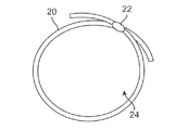
図2は、拡張具の一態様であって、尿の通路のための開口24を形成する拡張具20の上面図を示している。拡張具20は、拡張具部材の自由端の摺動解放及び固定を可能にしてもよい調整ロック機構22を介して、展開前又は展開中のいずれかにサイズ調整されてもよい。調整可能端部を備えたロック機構22は、本明細書に記載のとおり、拡張具20の直径を、特定の最長の長さ及び最短の長さの間で調整されるようにしてもよい。図3は、開口36を形成し、第2端部34を受容する開口を有する第1端部32を備える、他の様態に係る拡張具30の上面図を示している。第1端部32は、1つ以上の補完突起を規定する第2端部34を、第2端部34が第1端部32内に調整可能に摺動して端部間のラチェット調整及び固定を可能とするように受容する多数の突起を有した受容チャンネルを規定してもよい。
FIG. 2 shows a top view of the
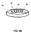
図4A及び図4Bの上面図及び斜視図は、他の様態を示し、貫通する開口50を形成する拡張具40を示している。本様態において、拡張具40の端部は、各端部に規定された開口42を通してピン又はロック44を介して互いに固定されてもよい。本様態は、一旦展開された拡張具40の拡張構成を支持するため、ハブ48に連結し、開口50を通じて伸びてもよい1つ以上の支柱46も組み込んでよい。
The top view and the perspective view of FIGS. 4A and 4B show another embodiment, showing an
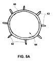
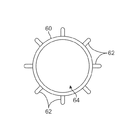
拡張具構造には、任意で、拡張具の周囲組織への固定を促進し、使用時の移動を防ぐ固定構造も組み込んでよい。図5A及び図5Bの上面図及び斜視図は、一様態に係る固定構造を示し、開口64を有し、拡張具60の外面から放射状に伸びる1つ以上の組織アンカー62を組み込んだ拡張具60を示している。単一の組織アンカー62が使用されてもよいが、拡張具60の外面に沿って、多数のアンカー62が均一又は任意のパターンで用いられてもよい。またこのようなアンカーは、例えば、フック型、返しとげ形状、V字形状等、拡張具の移動を防ぐのに役立つ任意の数の形状、パターン、又は突起で構成されてもよい。またアンカーは、拡張具60から放射状に伸びるのみでなく、互い違いに伸びるように構成されてよい。アンカーは、体内管腔内の拡張具60の搬送中には、低姿勢を採ることで組織壁との不用意な接触を防ぐものの、拡張具60の組織壁に対する展開時には、展開に際して血管壁に対向するように、例えば、回転又は再配置される等して、再構成されてもよい。アンカーは、拡張具60と同一の材料からなってもよく、或いは他の生体適合性材料からなってもよい。この特定の例ではアンカーについて説明したが、このようなアンカーは、本明細書に記載のような他の様態に係る拡張具のいずれかに任意で組み込まれてもよい。
The dilator structure may optionally incorporate a fixation structure that facilitates fixation of the dilator to the surrounding tissue and prevents movement during use. The top view and perspective view of FIGS. 5A and 5B illustrate a fixation structure according to one aspect, with a
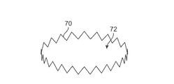
拡張具構造のさらに他の様態によると、図6の斜視図に示すとおり、拡張具70は、その周囲に周縁に沿って収縮及び拡張を促すことができる、例えば、ジグザグ構造、コイル状構造、正弦曲線状構造などの伸縮構造を備えたうえで、開口72を形成することとしてもよい。本様態によると、拡張具70は、収縮しなくなる所望の直径に拡張されてもよい。
According to yet another aspect of the dilator structure, as shown in the perspective view of FIG. 6, the
図7A及び図7Bの上面図は、他の様態による拡張具構造を示し、任意の数の多角形状(例えば、長方形、正方形、円形、三角形、楕円形等)に組み付けられてもよい別個の部分からなる要素を順に嵌め込むことによって形成されてもよい構造を示す。図7Aは、開口84を形成する、一様態に係る拡張アセンブリ80を示している。拡張具アセンブリ80は、交互の受容部分82のうち対応する雌チャンネル内に挿入する雄端部を形成する部分80を転換可能に受容するため、個々の受容部分82が一端又は両端に沿って雌受容チャンネルを形成することにより、八角形状(他の形状も可能である)を形成してもよい。雄端部と雌端部との間の連結は、組織壁に対して展開形状に拡張されてもよく、圧潰に抵抗する拡張具構造を提供するよう、一方向に構成されてもよい(例えば、受容部分82内のラチェット機構)。図7Bは、開口94を形成する、他の様態に係る拡張具アセンブリ90を示している。本様態によると、アセンブリ90は、調整可能な雄構造間に受容部分92を有する三角形状を形成してもよい。またアセンブリは、展開後の拡張具構造の移動を防ぐため、構造(本明細書に記載のとおり)の外形に沿った任意の数の固定様態を備えてもよい。
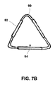
The top views of FIGS. 7A and 7B show dilator structures according to other aspects, and may be assembled into discrete parts that may be assembled into any number of polygonal shapes (eg, rectangular, square, circular, triangular, elliptical, etc.). 1 shows a structure that may be formed by fitting elements consisting of FIG. 7A shows an
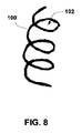
さらに他の様態によると、図8は、構造を通じて管腔102を規定する螺旋状構造又は渦巻き状構造に構成される他の拡張具100を示している。この拡張具100は、尿道内への搬送に際して低姿勢構成に維持される単一の一体構造で構成されてもよい。拡張具100は、一旦展開されると、組織壁に対して螺旋状構成又は渦巻き状構成に再構成してもよい。他の材料(本明細書に記載のとおり)も用いてよいが、超弾性体又はニチノールなどの形状記憶合金等の材料がこのような構造には好適であってもよい。
According to yet another aspect, FIG. 8 illustrates another
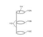
図9A〜図9Cの斜視図に、他の様態をさらに示す。図9Aは、コネクタ要素112を介して互いに連結される別個のリング状構造110A、110B、110Cが並べられることで、管腔114を形成する、一様態に係る単一の拡張具構造アセンブリを示している。この構造は、種々の断面形状を有するワイヤ、リボン、又はその他類似の構造によって形成されてもよい。例えば、ワイヤ又はリボンの断面は、円形、楕円形、長方形、正方形、台形等、任意の数の形状を形成してもよい。同一直線上に配列されたコネクタ要素112は、リング状構造110A、110B、110Cが非平面的で互いに平行となるよう、接線部分においてリング状構造110A、110B、110Cを連結する様子が示されている。しかしながら、他の様態において、リング状構造110A、110B、110Cは、互いに平行にせずに角度をもって配置されてもよい。リング状構造110A、110B、110Cは、他の様態では構造全体が単一の要素で形成されてもよいが、個別の構造に形成されてコネクタ要素112に連結されてもよい。
Other aspects are further illustrated in the perspective views of FIGS. 9A-9C. FIG. 9A shows a single dilator structure assembly according to one embodiment in which separate ring-
さらにこれらのリング状構造は単一の拡張具アセンブリとして形成されるが、リング状構造間の間隔は、本明細書に記載の個々の拡張具間の展開間隔と類似であってもよい。従って構造間の距離は、構造に対する組織上皮形成を促進するため、互いに、例えば、3mm〜20mmの範囲内のいずれか、離間してもよい。また隣接のリング状構造間の距離は、本明細書に記載の種々の実施形態のいずれかに適用されてもよい。 Furthermore, although these ring-like structures are formed as a single dilator assembly, the spacing between the ring-like structures may be similar to the deployment spacing between the individual dilators described herein. Accordingly, the distance between the structures may be spaced apart from each other, for example, in the range of 3 mm to 20 mm, in order to promote tissue epithelial formation for the structures. Also, the distance between adjacent ring structures may be applied to any of the various embodiments described herein.
また図示の様態は、リング状構造110A、110B、110Cが各前立腺葉の組織内に陥入されてもよいように、前立腺PRの3つの主要な前立腺葉の各々に沿って配置するため、3つのリング状構造110A、110B、110Cを有する。代替様態には、3つ未満又は3つを上回る数のリング状構造を有する構造や非円形の構造が含まれてよく、本明細書に記載のとおり、任意の数の他の形状が含まれてもよい。
Also, the illustrated embodiment is arranged for placement along each of the three major prostate lobes of the prostate PR so that the ring-shaped
図9Bは、3つのリング状構造120A、120B、120Cにより管腔124が形成され、コネクタ要素122を介してリング状構造120A、120B、120Cの各々も接続する単一の構造によって形成されてもよい他の様態を示す。ワイヤ、リボン、又はその他の類似の構造等の単一要素を使用して、リング状構造120A、120B、120Cが要素をループ化することによって形成される均一構造を形成してもよい。
FIG. 9B illustrates that a
図9Cは、リング状構造130A、130B、130Cが、コネクタ要素132A、132Bによって連結され、管腔134を形成し得る更なる他の様態の斜視図を示している。本様態において、コネクタ要素132A、132Bは、互いに平行であるが、リング状構造130A、130B、130Cの両端に沿って配置されてもよい。代替様態において、コネクタ要素132A、132Bは、両端に配置される代わりに、互いに他の角度で配置されてもよい。
FIG. 9C shows a perspective view of yet another aspect in which the ring-
図10は、リング状構造140A、140B、140Cが管腔144を形成してもよい、さらなる他の様態の斜視図を示すが、本様態において、いくつかのコネクタ要素142A、142B、142Cは、各リング状構造を互いに連結するため、互いに平行に配置されてもよい。本様態では、コネクタ要素142A、142B、142Cは、互いに均一に離間している様子が示されているが、これは任意の位置で離間してもよく、コネクタ要素の数は、2つであっても、3つを上回ってもよい。
FIG. 10 shows a perspective view of yet another aspect in which the ring-
図11は、管腔154を形成する構造150A、150Bに対して直角に方向付けられた単一のコネクタ要素152によって連結される2つのリング状構造150A、150Bを有する拡張具アセンブリのさらに他の様態を示す斜視図である。展開に際して、コネクタ要素152は、尿道管腔に対して長手方向に配列されるのに対して、リング状構造150A、150Bは、尿道管腔に対して横断する方向に沿うように方向付けられてもよい。本様態において、拡張具アセンブリは、拡張具アセンブリ内に構成される、単一且つ均一の要素から形成されてもよい。とはいえ、リング状構造150A、150Bの末端において、周辺組織に対して鋭利でない無傷先端部156を形成し、周辺組織に対するあらゆる穿孔を防ぐように拡張されてもよい。
FIG. 11 shows yet another dilator assembly having two ring-
図12は、管腔164を形成する2つのリング状構造160A、160Bを有する拡張具アセンブリのさらに他の様態であって、構造160A、160Bが単一のコネクタ要素162によって連結される様態を示す斜視図である。要素162は、展開時、アセンブリが連続的に屈曲する、あるいは、アーチ型構造をとるように、構造160A、160Bから屈曲するように構成してもよい。リング状構造160A、160Bの末端もまた、鋭利でない無傷先端部166を構成するよう、拡張してもよい。
FIG. 12 illustrates yet another aspect of a dilator assembly having two ring-
リング状構造上の鋭利でない無傷先端部は、実行可能となるように、本明細書に記載の実施形態に係る拡張具のいずれかに任意で組み込まれてもよい。例えば、図1C、図8、及び図9A〜図9C等、いずれかの図面に示された実施形態において任意でこのような先端部を組み込んでもよい。 A non-sharp intact tip on the ring-like structure may optionally be incorporated into any of the dilators according to the embodiments described herein to be feasible. For example, such a tip may optionally be incorporated in the embodiments shown in any of the drawings, such as FIGS. 1C, 8 and 9A-9C.
図13は、尿道前立腺部PU内に展開される図11の拡張具アセンブリの一例を示す斜視図である。本例において、単一拡張アセンブリ170、172は各々、2つのリング状構造を有してもよく、拡張アセンブリ170、172は、尿道内に隣接して展開されることにより、尿道を開放状態に維持する連続的構造を形成してもよい。上述のとおり、アセンブリ170、172は各々、展開用に、1つ以上、例えば、2〜4の範囲内のいずれかのリング状構造又はコイルを有してもよい。さらに、拡張具アセンブリ170内のリング状構造間の間隔は、隣接アセンブリ172のリング状構造間の間隔とともに、例えば、3mm〜20mmの範囲内のいずれかで互いに離間することにより、構造の組織上皮形成を促進してもよい。
13 is a perspective view showing an example of the dilator assembly of FIG. 11 deployed in the urethral prostate unit PU. In this example, each
3つの構造を(例えば、前立腺PRの3つの主要な前立腺葉の各々に対して配置するために)用いる、図示の各拡張具構成は、他の様態では、3つ未満の構造又は3つを上回る構造を備えてもよい。また構造間の相対的間隔も変化してもよく、構造自体が互いに角度をもって配置されてもよい。また構造のうちのいずれかは、任意の数の種々の組み合わせにおいて、本明細書に記載の固定構造、種々の塗布又は被覆等、表面改質のいずれかを任意で組み込んでもよい。 Each of the illustrated dilator configurations using three structures (eg, for placement against each of the three major prostate lobes of the prostate PR), in other aspects, uses less than three structures or three. You may provide the structure which exceeds. Also, the relative spacing between the structures may vary, and the structures themselves may be arranged at an angle to each other. Also, any of the structures may optionally incorporate any of the surface modifications, such as the fixed structure described herein, various coatings or coatings, in any number of different combinations.
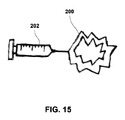
本明細書に記載の種々の拡張具アセンブリのいずれかを展開するに際し、種々の装備が採用されてもよい。図14Aの側面図は、そのような装備の一例を示し、患者の尿道内への挿入に好適な直径及び長さを有する長尺の軸180を備えた搬送展開器具を示している。軸180は、例えば、尿道口UO内を進行し、且つ、少なくとも部分的に尿道前立腺部PU内へと進行できる程度の、固定の長さ、又は部分的に伸縮性を有する長さで形成されてもよい。軸180は、その遠位端あるいはその付近にバルーン180のような膨張部材を備えてよく、また、バルーン182には、管腔内搬送のために低姿勢にした拡張具184を備えてもよい。バルーン182は、一旦体内管腔内に好適に配置されると、1つ以上の拡張具184を管腔壁に接触させるように展開すべく、拡張されてもよい。バルーン182は、一旦展開されると、患者の体内から除去するために圧潰することとしてもよい。図14Bは、1つ以上の拡張具194を組織壁に対して展開させるための傘状拡張機構192を有する、他の様態に係る軸190の側面図を示している。図15は、外面上に1つ以上の拡張具を支持し得る感情拡張具を拡張する拡張容器202及び管状拡張具200を有する、さらに他の様態に係る展開器具の側面図を示している。
In deploying any of the various dilator assemblies described herein, various equipment may be employed. The side view of FIG. 14A shows an example of such equipment, showing a delivery and deployment device with an
他の様態によると、図16の側面図に示すとおり、内視鏡又は膀胱鏡等の展開器具210により、その内部に1つ以上の拡張具が低姿勢構成に維持されつつ配置される搬送管腔212(例えば、直径2mm未満)を実現してもよい。展開器具210が一旦好適に配置された際に、制御下で1つ以上の拡張具を搬送管腔212から推し進めるために、推進機構あるいは放出機構を用いてもよい。また展開器具のいずれにおいても、体内管腔内の装置進行を促進する任意の数の可動部品を組み込んでもよい。リング状構造150A、150B、及び接続要素152に示すように、低姿勢構造をなす拡張具アセンブリの低姿勢構造を維持するために、別個のシース214が、搬送管腔212から進行又は延長されてもよい。シース214は、種々の材料(例えば、PEEK、ポリイミド、ステンレス鋼、ニチノール等)からなってもよく、器具210の進行及び/又は可動性を阻害しないように、強度、最長内径、及び可塑性が最適化されてもよい。1つ又はいくつかの拡張具アセンブリは、複数の拡張具が単一の処置により連続展開できるように、装備210内に配置されてもよい。
According to another aspect, as shown in the side view of FIG. 16, a delivery tube in which one or more dilators are maintained in a low-position configuration by a
拡張具アセンブリが器具210から一旦搬送されると、拡張具は、その超弾性又は形状記憶特性により、組織壁に接触した展開拡張構成へと再構成されることとしてもよい。或いは、本明細書に記載のとおり、他の起動機構を使用して、拡張具の再構成又は再構成の促進を行ってもよい。
Once the dilator assembly is transported from the
展開器具210は、例えば、展開器具210と一体化又は分離されてもよい撮像装置216を有する、内視鏡又は膀胱鏡等の管腔内可視化システムを用いて、体内管腔内で進行及び配置されてもよい。可視化システムは、展開処置前、又は展開処置中のいずれかに用いられてもよい。他の様態によると、外部撮像方式(例えば、超音波、コンピュータ断層撮影、磁気共振撮像等)が、展開器具(及び/又は、管腔内可視化システム)との組み合わせで使用されてもよい。他の様態によると、バルーン又はその他の配置参照システムは、拡張具の適正な解剖学的配置を保証するために、例えば、膀胱BL内又はその他の箇所に配されてもよい。
The
システムは、任意で、1つ以上の拡張具の調整及び/又は後退を行う装置及び方法も備えてよい。本様態の一実施形態に係るシステムは、捕捉機構を備えてもよい(例えば、標準捕捉ツールが使用されてもよい)。他の様態によると、調整及び/又は除去を促進するように装置を調整する加熱要素又は冷却要素も備えられてよい。 The system may optionally also include an apparatus and method for adjusting and / or retracting one or more dilators. A system according to an embodiment of the present aspect may include a capture mechanism (eg, a standard capture tool may be used). According to other aspects, heating or cooling elements that adjust the apparatus to facilitate adjustment and / or removal may also be provided.
以上に述べた本開示の発明の適用は、特定の治療又は体内領域に限定されるものでなく、任意の数の他の治療及び体内領域も含まれてよい。当業者にとって明らかである、本発明を実施するための上述の方法及び装置並びに本発明の種々の様態に変更を加えたものも、本開示の範囲内であることを意図するものである。さらに実施例間の様態の種々の組み合わせも、同様に、本開示の範囲内と考慮及び解釈される。 The application of the presently disclosed invention described above is not limited to a particular treatment or body region, but may include any number of other treatments and body regions. Modifications to the above-described methods and apparatus for practicing the invention and various aspects of the invention that are apparent to those skilled in the art are intended to be within the scope of the disclosure. Further, various combinations of aspects between the embodiments are similarly considered and interpreted within the scope of the present disclosure.
BL 膀胱
BN 膀胱顎
BU 尿道球部
MU 尿道膜性部
PR 前立腺
PU 尿道前立腺部
SP 括約筋
UO 尿道口
10 拡張構造(構造、拡張具)
20、30、40、60、70、80、90、100 拡張具
22 調整ロック機構
24、36、50、64、72、84、94 開口
32 第1端部
34 第2端部
42 開口
44 ピン又はロック
46 支柱
48 ハブ
62 組織アンカー
80、90 拡張具アセンブリ
82 受容部分
102、114、124、134、144、154 管腔
110A、110B、110C、120A、120B、120C、130A、130B、130C、140A、140B、140C リング状構造
112、122、132A、132B、142A、142B、142C コネクタ要素
170、172 拡張アセンブリ
182 バルーン
180、190 軸
BL bladder BN bladder jaw BU urethral bulb MU urethral part PR prostate PU urethral prostate SP sphincter muscle UO
20, 30, 40, 60, 70, 80, 90, 100
Claims (18)
開口を形成し、前記体内管腔の内層組織に接触する拡張具構造を備え、
前記拡張具構造は、前記体内管腔の直径より0〜60%大きなサイズの直径を有し、
前記拡張具構造は、前記体内管腔の開存性を維持しつつ、前記体内管腔の前記内層組織内に陥入させる高さを有する装置。 A device for maintaining the patency of a body lumen,
An expander structure that forms an opening and contacts the inner layer tissue of the body lumen;
The dilator structure has a diameter that is 0-60% larger than the diameter of the body lumen;
The device having a height that allows the dilator structure to be inserted into the inner layer tissue of the body lumen while maintaining the patency of the body lumen.
開口を形成する少なくとも1つの拡張具構造を、開放構成の維持対象である体内管腔付近に進めるステップと、
前記少なくとも1つの拡張具構造が展開構成で前記体内管腔の直径より0%〜60%大きな直径を有するように、前記体内管腔の内層組織に対して前記少なくとも1つの拡張具構造を展開するステップと、
前記少なくとも1つの拡張具構造が前記体内管腔の開存性を維持しつつ、前記体内管腔の前記内層組織内に部分的又は完全に陥入されるように、前記体内管腔内に前記少なくとも1つの拡張具構造の位置を維持するステップとを備える方法。 A method of maintaining patency of a body lumen,
Advancing at least one dilator structure forming an opening near a body lumen that is to be maintained in an open configuration;
Deploying the at least one dilator structure against the inner tissue of the body lumen such that the at least one dilator structure has a diameter that is 0% to 60% greater than the diameter of the body lumen in a deployed configuration. Steps,
In the body lumen, the at least one dilator structure is partially or fully invaginated in the inner tissue of the body lumen while maintaining the patency of the body lumen. Maintaining the position of at least one dilator structure.
Applications Claiming Priority (5)
| Application Number | Priority Date | Filing Date | Title |
|---|---|---|---|
| US201461953212P | 2014-03-14 | 2014-03-14 | |
| US61/953,212 | 2014-03-14 | ||
| US201462035826P | 2014-08-11 | 2014-08-11 | |
| US62/035,826 | 2014-08-11 | ||
| PCT/US2015/020235 WO2015138763A1 (en) | 2014-03-14 | 2015-03-12 | Indwelling body lumen expander |
Related Child Applications (1)
| Application Number | Title | Priority Date | Filing Date |
|---|---|---|---|
| JP2019028438A Division JP2019072595A (en) | 2014-03-14 | 2019-02-20 | Indwelling body lumen expander |
Publications (2)
| Publication Number | Publication Date |
|---|---|
| JP2017507752A true JP2017507752A (en) | 2017-03-23 |
| JP6734782B2 JP6734782B2 (en) | 2020-08-05 |
Family
ID=54067701
Family Applications (4)
| Application Number | Title | Priority Date | Filing Date |
|---|---|---|---|
| JP2016557555A Active JP6734782B2 (en) | 2014-03-14 | 2015-03-12 | Indwelling body lumen dilator |
| JP2019028438A Withdrawn JP2019072595A (en) | 2014-03-14 | 2019-02-20 | Indwelling body lumen expander |
| JP2021021636A Pending JP2021073041A (en) | 2014-03-14 | 2021-02-15 | Indwelling body lumen expander |
| JP2021021635A Pending JP2021073040A (en) | 2014-03-14 | 2021-02-15 | Indwelling body lumen expander |
Family Applications After (3)
| Application Number | Title | Priority Date | Filing Date |
|---|---|---|---|
| JP2019028438A Withdrawn JP2019072595A (en) | 2014-03-14 | 2019-02-20 | Indwelling body lumen expander |
| JP2021021636A Pending JP2021073041A (en) | 2014-03-14 | 2021-02-15 | Indwelling body lumen expander |
| JP2021021635A Pending JP2021073040A (en) | 2014-03-14 | 2021-02-15 | Indwelling body lumen expander |
Country Status (7)
| Country | Link |
|---|---|
| US (3) | US20150257908A1 (en) |
| EP (1) | EP3116583B1 (en) |
| JP (4) | JP6734782B2 (en) |
| CN (1) | CN106456949B (en) |
| AU (2) | AU2015229323B2 (en) |
| CA (1) | CA2942494C (en) |
| WO (1) | WO2015138763A1 (en) |
Cited By (3)
| Publication number | Priority date | Publication date | Assignee | Title |
|---|---|---|---|---|
| JP2020528790A (en) * | 2017-07-28 | 2020-10-01 | ゼンフロー, インコーポレイテッド | Systems, devices, and methods for dilating the diameter of the prostatic urethra |
| US11547546B2 (en) | 2015-12-22 | 2023-01-10 | Prodeon Medical Corporation | System and method for increasing a cross-sectional area of a body lumen |
| US12090040B2 (en) | 2016-12-09 | 2024-09-17 | Zenflow, Inc. | Methods for deployment of an implant |
Families Citing this family (24)
| Publication number | Priority date | Publication date | Assignee | Title |
|---|---|---|---|---|
| US8668705B2 (en) | 2005-05-20 | 2014-03-11 | Neotract, Inc. | Latching anchor device |
| US10195014B2 (en) | 2005-05-20 | 2019-02-05 | Neotract, Inc. | Devices, systems and methods for treating benign prostatic hyperplasia and other conditions |
| US7758594B2 (en) | 2005-05-20 | 2010-07-20 | Neotract, Inc. | Devices, systems and methods for treating benign prostatic hyperplasia and other conditions |
| US8603106B2 (en) | 2005-05-20 | 2013-12-10 | Neotract, Inc. | Integrated handle assembly for anchor delivery system |
| US8628542B2 (en) | 2005-05-20 | 2014-01-14 | Neotract, Inc. | Median lobe destruction apparatus and method |
| US10925587B2 (en) | 2005-05-20 | 2021-02-23 | Neotract, Inc. | Anchor delivery system |
| US9549739B2 (en) | 2005-05-20 | 2017-01-24 | Neotract, Inc. | Devices, systems and methods for treating benign prostatic hyperplasia and other conditions |
| US7645286B2 (en) | 2005-05-20 | 2010-01-12 | Neotract, Inc. | Devices, systems and methods for retracting, lifting, compressing, supporting or repositioning tissues or anatomical structures |
| US10292801B2 (en) | 2012-03-29 | 2019-05-21 | Neotract, Inc. | System for delivering anchors for treating incontinence |
| US10130353B2 (en) | 2012-06-29 | 2018-11-20 | Neotract, Inc. | Flexible system for delivering an anchor |
| EP3167845A1 (en) | 2015-11-12 | 2017-05-17 | The Provost, Fellows, Foundation Scholars, & the other members of Board, of the College of Holy and Undiv. Trinity of Queen Elizabeth near Dublin | An implantable biocompatible expander suitable for treatment of constrictions of body lumen |
| US20170231650A1 (en) * | 2016-02-16 | 2017-08-17 | Peter Sayet | Endoscope Attachable Cystolith Entrapment Apparatus |
| WO2017141805A1 (en) * | 2016-02-16 | 2017-08-24 | 株式会社Pentas | Stent |
| AU2017254659B2 (en) * | 2016-04-21 | 2022-10-06 | Zenflow, Inc. | Systems and methods for implants and deployment devices |
| EP3618914B1 (en) | 2017-05-05 | 2023-10-18 | Prodeon Medical Corporation | Implantable devices to treat benign prostate hyperplasia (bph) and associated lower urinary tract symptoms (luts) |
| CN116803360A (en) | 2017-12-06 | 2023-09-26 | 蝴蝶医疗有限公司 | Urological implant |
| EP4218632A1 (en) | 2017-12-23 | 2023-08-02 | Teleflex Life Sciences Limited | Expandable tissue engagement apparatus |
| US12076226B2 (en) | 2018-03-19 | 2024-09-03 | Butterfly Medical Ltd. | Urological implant having extraction handle and/or arched members |
| WO2019180711A1 (en) * | 2018-03-19 | 2019-09-26 | Medi-Tate Ltd. | Urethral implant delivery system and method |
| CN112384169A (en) * | 2018-05-17 | 2021-02-19 | 真复灵公司 | Systems, devices, and methods for proper deployment and imaging of implants in the prostatic urethra |
| EP4061292A4 (en) | 2019-11-19 | 2023-12-27 | Zenflow, Inc. | Systems, devices, and methods for the accurate deployment and imaging of an implant in the prostatic urethra |
| US11273025B2 (en) | 2019-11-22 | 2022-03-15 | Pro Verum Limited | Expandable implant delivery device |
| US11602621B2 (en) | 2019-11-22 | 2023-03-14 | ProVerum Limited | Device for controllably deploying expandable implants |
| DE102023105518A1 (en) | 2023-03-06 | 2024-09-12 | Olympus Winter & Ibe Gmbh | Implant |
Citations (4)
| Publication number | Priority date | Publication date | Assignee | Title |
|---|---|---|---|---|
| US4856516A (en) * | 1989-01-09 | 1989-08-15 | Cordis Corporation | Endovascular stent apparatus and method |
| WO1993013824A1 (en) * | 1992-01-20 | 1993-07-22 | Engineers & Doctors A/S | Segmentarily expandable tubular endoluminal prosthesis |
| JP2009517145A (en) * | 2005-12-02 | 2009-04-30 | ピーエヌエヌ メディカル エイ/エス | Stent |
| US20120253451A1 (en) * | 2002-10-11 | 2012-10-04 | Sahatjian Ronald A | Implantable medical devices |
Family Cites Families (34)
| Publication number | Priority date | Publication date | Assignee | Title |
|---|---|---|---|---|
| JP2726696B2 (en) * | 1989-03-27 | 1998-03-11 | 日本ゼオン株式会社 | Biological dilator and catheter |
| JPH0475668A (en) * | 1990-07-19 | 1992-03-10 | Kato Hatsujo Kaisha Ltd | Treatment tool for endoscope |
| US5269802A (en) * | 1991-09-10 | 1993-12-14 | Garber Bruce B | Prostatic stent |
| US5354309A (en) * | 1991-10-11 | 1994-10-11 | Angiomed Ag | Apparatus for widening a stenosis in a body cavity |
| CA2380683C (en) * | 1991-10-28 | 2006-08-08 | Advanced Cardiovascular Systems, Inc. | Expandable stents and method for making same |
| FR2706764B1 (en) * | 1993-06-24 | 1995-08-04 | Synthelabo | |
| US5554181A (en) * | 1994-05-04 | 1996-09-10 | Regents Of The University Of Minnesota | Stent |
| US7846202B2 (en) * | 1995-06-07 | 2010-12-07 | Cook Incorporated | Coated implantable medical device |
| JPH105343A (en) * | 1996-06-21 | 1998-01-13 | Piolax Inc | Treatment instrument for lumen |
| CN1176831A (en) * | 1996-09-18 | 1998-03-25 | 崔连群 | Self-locking type inner blood vessel dilator |
| WO1998020810A1 (en) * | 1996-11-12 | 1998-05-22 | Medtronic, Inc. | Flexible, radially expansible luminal prostheses |
| US5980554A (en) * | 1997-05-05 | 1999-11-09 | Micro Therapeutics, Inc. | Wire frame partial flow obstruction for aneurysm treatment |
| US6033436A (en) * | 1998-02-17 | 2000-03-07 | Md3, Inc. | Expandable stent |
| US7192442B2 (en) * | 1999-06-30 | 2007-03-20 | Edwards Lifesciences Ag | Method and device for treatment of mitral insufficiency |
| WO2001021247A1 (en) * | 1999-09-20 | 2001-03-29 | Appriva Medical, Inc. | Method and apparatus for closing a body lumen |
| US6302907B1 (en) * | 1999-10-05 | 2001-10-16 | Scimed Life Systems, Inc. | Flexible endoluminal stent and process of manufacture |
| US20030135268A1 (en) * | 2000-04-11 | 2003-07-17 | Ashvin Desai | Secure stent for maintaining a lumenal opening |
| US20020077693A1 (en) * | 2000-12-19 | 2002-06-20 | Barclay Bruce J. | Covered, coiled drug delivery stent and method |
| JPWO2003022346A1 (en) * | 2001-09-07 | 2004-12-24 | 株式会社塚田メディカル・リサーチ | Prostate hypertrophy treatment catheter |
| US6770101B2 (en) * | 2001-10-09 | 2004-08-03 | Scimed Life Systems, Inc. | Prostatic stent and delivery system |
| US6733536B1 (en) * | 2002-10-22 | 2004-05-11 | Scimed Life Systems | Male urethral stent device |
| US8282678B2 (en) * | 2002-11-13 | 2012-10-09 | Allium Medical Solutions Ltd. | Endoluminal lining |
| US20040193246A1 (en) * | 2003-03-25 | 2004-09-30 | Microvention, Inc. | Methods and apparatus for treating aneurysms and other vascular defects |
| US8043357B2 (en) * | 2003-10-10 | 2011-10-25 | Cook Medical Technologies Llc | Ring stent |
| JP4465008B2 (en) * | 2004-09-21 | 2010-05-19 | ウィリアム・エイ・クック・オーストラリア・プロプライエタリー・リミテッド | Stent graft connection structure |
| JP4686711B2 (en) * | 2005-03-30 | 2011-05-25 | 国立大学法人山口大学 | Biological duct dilator and catheter |
| US20070066869A1 (en) * | 2005-09-21 | 2007-03-22 | David Hoffman | Endoscopic assembly including cap and sheath |
| ATE477765T1 (en) * | 2005-10-29 | 2010-09-15 | Pnn Medical Sa | STENT WITH ANCHORING PART |
| CN101500516B (en) * | 2006-08-02 | 2011-08-24 | 马尼株式会社 | Stent |
| US9232959B2 (en) * | 2007-01-02 | 2016-01-12 | Aquabeam, Llc | Multi fluid tissue resection methods and devices |
| US20100130815A1 (en) * | 2007-05-18 | 2010-05-27 | Prostaplant Ltd. | Intraurethral and extraurethral apparatus |
| WO2010124126A2 (en) * | 2009-04-22 | 2010-10-28 | The Regents Of The University Of California | Expandable distension device for hollow organ growth |
| US20110295353A1 (en) * | 2010-04-29 | 2011-12-01 | Vanderbilt University | Patent body lumen stent |
| WO2012015825A2 (en) * | 2010-07-27 | 2012-02-02 | Incept, Llc | Methods and apparatus for treating neurovascular venous outflow obstruction |
-
2015
- 2015-03-12 JP JP2016557555A patent/JP6734782B2/en active Active
- 2015-03-12 CA CA2942494A patent/CA2942494C/en active Active
- 2015-03-12 CN CN201580013396.6A patent/CN106456949B/en active Active
- 2015-03-12 EP EP15760826.6A patent/EP3116583B1/en active Active
- 2015-03-12 AU AU2015229323A patent/AU2015229323B2/en active Active
- 2015-03-12 WO PCT/US2015/020235 patent/WO2015138763A1/en active Application Filing
- 2015-03-12 US US14/656,402 patent/US20150257908A1/en not_active Abandoned
-
2018
- 2018-12-12 US US16/218,007 patent/US20190117423A1/en not_active Abandoned
-
2019
- 2019-02-20 JP JP2019028438A patent/JP2019072595A/en not_active Withdrawn
-
2020
- 2020-02-05 AU AU2020200817A patent/AU2020200817B2/en active Active
-
2021
- 2021-02-15 JP JP2021021636A patent/JP2021073041A/en active Pending
- 2021-02-15 JP JP2021021635A patent/JP2021073040A/en active Pending
-
2023
- 2023-03-02 US US18/177,619 patent/US20240293215A1/en active Pending
Patent Citations (4)
| Publication number | Priority date | Publication date | Assignee | Title |
|---|---|---|---|---|
| US4856516A (en) * | 1989-01-09 | 1989-08-15 | Cordis Corporation | Endovascular stent apparatus and method |
| WO1993013824A1 (en) * | 1992-01-20 | 1993-07-22 | Engineers & Doctors A/S | Segmentarily expandable tubular endoluminal prosthesis |
| US20120253451A1 (en) * | 2002-10-11 | 2012-10-04 | Sahatjian Ronald A | Implantable medical devices |
| JP2009517145A (en) * | 2005-12-02 | 2009-04-30 | ピーエヌエヌ メディカル エイ/エス | Stent |
Cited By (3)
| Publication number | Priority date | Publication date | Assignee | Title |
|---|---|---|---|---|
| US11547546B2 (en) | 2015-12-22 | 2023-01-10 | Prodeon Medical Corporation | System and method for increasing a cross-sectional area of a body lumen |
| US12090040B2 (en) | 2016-12-09 | 2024-09-17 | Zenflow, Inc. | Methods for deployment of an implant |
| JP2020528790A (en) * | 2017-07-28 | 2020-10-01 | ゼンフロー, インコーポレイテッド | Systems, devices, and methods for dilating the diameter of the prostatic urethra |
Also Published As
| Publication number | Publication date |
|---|---|
| CN106456949B (en) | 2019-11-01 |
| US20190117423A1 (en) | 2019-04-25 |
| JP2021073041A (en) | 2021-05-13 |
| CA2942494A1 (en) | 2015-09-17 |
| JP2021073040A (en) | 2021-05-13 |
| EP3116583A4 (en) | 2017-10-25 |
| CA2942494C (en) | 2022-04-19 |
| EP3116583A1 (en) | 2017-01-18 |
| US20150257908A1 (en) | 2015-09-17 |
| EP3116583B1 (en) | 2024-03-06 |
| JP6734782B2 (en) | 2020-08-05 |
| JP2019072595A (en) | 2019-05-16 |
| CN106456949A (en) | 2017-02-22 |
| AU2020200817B2 (en) | 2022-02-17 |
| AU2020200817A1 (en) | 2020-02-20 |
| AU2015229323B2 (en) | 2019-11-07 |
| AU2015229323A1 (en) | 2016-09-22 |
| WO2015138763A1 (en) | 2015-09-17 |
| US20240293215A1 (en) | 2024-09-05 |
Similar Documents
| Publication | Publication Date | Title |
|---|---|---|
| AU2020200817B2 (en) | Indwelling body lumen expander | |
| KR102487146B1 (en) | Implants for treating benign prostatic hyperplasia (BPH) and lower urinary tract symptoms (LUTS) | |
| US9333102B2 (en) | Stent | |
| EP3167845A1 (en) | An implantable biocompatible expander suitable for treatment of constrictions of body lumen | |
| US20120290065A1 (en) | Pre-Positioned Anastomosis Device and Related Methods of Use | |
| US20200323618A1 (en) | Systems, devices, and methods for expanding the diameter of the prostatic urethra | |
| JPH08510152A (en) | Stent delivery system | |
| EP3281668B1 (en) | Solid wire ureteral stent | |
| BR112019021937B1 (en) | RETRIEVEABLE IMPLANT | |
| IL169830A (en) | Stent |
Legal Events
| Date | Code | Title | Description |
|---|---|---|---|
| A521 | Request for written amendment filed |
Free format text: JAPANESE INTERMEDIATE CODE: A523 Effective date: 20160914 |
|
| A521 | Request for written amendment filed |
Free format text: JAPANESE INTERMEDIATE CODE: A523 Effective date: 20170210 |
|
| A621 | Written request for application examination |
Free format text: JAPANESE INTERMEDIATE CODE: A621 Effective date: 20170927 |
|
| A521 | Request for written amendment filed |
Free format text: JAPANESE INTERMEDIATE CODE: A523 Effective date: 20171024 |
|
| A131 | Notification of reasons for refusal |
Free format text: JAPANESE INTERMEDIATE CODE: A131 Effective date: 20180710 |
|
| RD02 | Notification of acceptance of power of attorney |
Free format text: JAPANESE INTERMEDIATE CODE: A7422 Effective date: 20180814 |
|
| A521 | Request for written amendment filed |
Free format text: JAPANESE INTERMEDIATE CODE: A523 Effective date: 20181010 |
|
| A02 | Decision of refusal |
Free format text: JAPANESE INTERMEDIATE CODE: A02 Effective date: 20181023 |
|
| RD03 | Notification of appointment of power of attorney |
Free format text: JAPANESE INTERMEDIATE CODE: A7423 Effective date: 20181207 |
|
| RD04 | Notification of resignation of power of attorney |
Free format text: JAPANESE INTERMEDIATE CODE: A7424 Effective date: 20181210 |
|
| RD04 | Notification of resignation of power of attorney |
Free format text: JAPANESE INTERMEDIATE CODE: A7424 Effective date: 20181211 |
|
| A521 | Request for written amendment filed |
Free format text: JAPANESE INTERMEDIATE CODE: A523 Effective date: 20190220 |
|
| A911 | Transfer to examiner for re-examination before appeal (zenchi) |
Free format text: JAPANESE INTERMEDIATE CODE: A911 Effective date: 20190228 |
|
| A912 | Re-examination (zenchi) completed and case transferred to appeal board |
Free format text: JAPANESE INTERMEDIATE CODE: A912 Effective date: 20190412 |
|
| A521 | Request for written amendment filed |
Free format text: JAPANESE INTERMEDIATE CODE: A523 Effective date: 20200518 |
|
| A61 | First payment of annual fees (during grant procedure) |
Free format text: JAPANESE INTERMEDIATE CODE: A61 Effective date: 20200710 |
|
| R150 | Certificate of patent or registration of utility model |
Ref document number: 6734782 Country of ref document: JP Free format text: JAPANESE INTERMEDIATE CODE: R150 |
|
| R250 | Receipt of annual fees |
Free format text: JAPANESE INTERMEDIATE CODE: R250 |