CN112384169A - Systems, devices, and methods for proper deployment and imaging of implants in the prostatic urethra - Google Patents
Systems, devices, and methods for proper deployment and imaging of implants in the prostatic urethra Download PDFInfo
- Publication number
- CN112384169A CN112384169A CN201980033236.6A CN201980033236A CN112384169A CN 112384169 A CN112384169 A CN 112384169A CN 201980033236 A CN201980033236 A CN 201980033236A CN 112384169 A CN112384169 A CN 112384169A
- Authority
- CN
- China
- Prior art keywords
- implant
- tubular member
- distal
- control device
- proximal
- Prior art date
- Legal status (The legal status is an assumption and is not a legal conclusion. Google has not performed a legal analysis and makes no representation as to the accuracy of the status listed.)
- Pending
Links
Images


Classifications
-
- A—HUMAN NECESSITIES
- A61—MEDICAL OR VETERINARY SCIENCE; HYGIENE
- A61F—FILTERS IMPLANTABLE INTO BLOOD VESSELS; PROSTHESES; DEVICES PROVIDING PATENCY TO, OR PREVENTING COLLAPSING OF, TUBULAR STRUCTURES OF THE BODY, e.g. STENTS; ORTHOPAEDIC, NURSING OR CONTRACEPTIVE DEVICES; FOMENTATION; TREATMENT OR PROTECTION OF EYES OR EARS; BANDAGES, DRESSINGS OR ABSORBENT PADS; FIRST-AID KITS
- A61F2/00—Filters implantable into blood vessels; Prostheses, i.e. artificial substitutes or replacements for parts of the body; Appliances for connecting them with the body; Devices providing patency to, or preventing collapsing of, tubular structures of the body, e.g. stents
- A61F2/95—Instruments specially adapted for placement or removal of stents or stent-grafts
- A61F2/962—Instruments specially adapted for placement or removal of stents or stent-grafts having an outer sleeve
- A61F2/966—Instruments specially adapted for placement or removal of stents or stent-grafts having an outer sleeve with relative longitudinal movement between outer sleeve and prosthesis, e.g. using a push rod
-
- A—HUMAN NECESSITIES
- A61—MEDICAL OR VETERINARY SCIENCE; HYGIENE
- A61B—DIAGNOSIS; SURGERY; IDENTIFICATION
- A61B1/00—Instruments for performing medical examinations of the interior of cavities or tubes of the body by visual or photographical inspection, e.g. endoscopes; Illuminating arrangements therefor
- A61B1/00064—Constructional details of the endoscope body
- A61B1/00071—Insertion part of the endoscope body
- A61B1/0008—Insertion part of the endoscope body characterised by distal tip features
- A61B1/00082—Balloons
-
- A—HUMAN NECESSITIES
- A61—MEDICAL OR VETERINARY SCIENCE; HYGIENE
- A61B—DIAGNOSIS; SURGERY; IDENTIFICATION
- A61B1/00—Instruments for performing medical examinations of the interior of cavities or tubes of the body by visual or photographical inspection, e.g. endoscopes; Illuminating arrangements therefor
- A61B1/00064—Constructional details of the endoscope body
- A61B1/00071—Insertion part of the endoscope body
- A61B1/0008—Insertion part of the endoscope body characterised by distal tip features
- A61B1/00087—Tools
-
- A—HUMAN NECESSITIES
- A61—MEDICAL OR VETERINARY SCIENCE; HYGIENE
- A61B—DIAGNOSIS; SURGERY; IDENTIFICATION
- A61B1/00—Instruments for performing medical examinations of the interior of cavities or tubes of the body by visual or photographical inspection, e.g. endoscopes; Illuminating arrangements therefor
- A61B1/005—Flexible endoscopes
-
- A—HUMAN NECESSITIES
- A61—MEDICAL OR VETERINARY SCIENCE; HYGIENE
- A61B—DIAGNOSIS; SURGERY; IDENTIFICATION
- A61B1/00—Instruments for performing medical examinations of the interior of cavities or tubes of the body by visual or photographical inspection, e.g. endoscopes; Illuminating arrangements therefor
- A61B1/04—Instruments for performing medical examinations of the interior of cavities or tubes of the body by visual or photographical inspection, e.g. endoscopes; Illuminating arrangements therefor combined with photographic or television appliances
- A61B1/05—Instruments for performing medical examinations of the interior of cavities or tubes of the body by visual or photographical inspection, e.g. endoscopes; Illuminating arrangements therefor combined with photographic or television appliances characterised by the image sensor, e.g. camera, being in the distal end portion
-
- A—HUMAN NECESSITIES
- A61—MEDICAL OR VETERINARY SCIENCE; HYGIENE
- A61B—DIAGNOSIS; SURGERY; IDENTIFICATION
- A61B1/00—Instruments for performing medical examinations of the interior of cavities or tubes of the body by visual or photographical inspection, e.g. endoscopes; Illuminating arrangements therefor
- A61B1/06—Instruments for performing medical examinations of the interior of cavities or tubes of the body by visual or photographical inspection, e.g. endoscopes; Illuminating arrangements therefor with illuminating arrangements
- A61B1/0661—Endoscope light sources
- A61B1/0676—Endoscope light sources at distal tip of an endoscope
-
- A—HUMAN NECESSITIES
- A61—MEDICAL OR VETERINARY SCIENCE; HYGIENE
- A61B—DIAGNOSIS; SURGERY; IDENTIFICATION
- A61B1/00—Instruments for performing medical examinations of the interior of cavities or tubes of the body by visual or photographical inspection, e.g. endoscopes; Illuminating arrangements therefor
- A61B1/307—Instruments for performing medical examinations of the interior of cavities or tubes of the body by visual or photographical inspection, e.g. endoscopes; Illuminating arrangements therefor for the urinary organs, e.g. urethroscopes, cystoscopes
-
- A—HUMAN NECESSITIES
- A61—MEDICAL OR VETERINARY SCIENCE; HYGIENE
- A61F—FILTERS IMPLANTABLE INTO BLOOD VESSELS; PROSTHESES; DEVICES PROVIDING PATENCY TO, OR PREVENTING COLLAPSING OF, TUBULAR STRUCTURES OF THE BODY, e.g. STENTS; ORTHOPAEDIC, NURSING OR CONTRACEPTIVE DEVICES; FOMENTATION; TREATMENT OR PROTECTION OF EYES OR EARS; BANDAGES, DRESSINGS OR ABSORBENT PADS; FIRST-AID KITS
- A61F2/00—Filters implantable into blood vessels; Prostheses, i.e. artificial substitutes or replacements for parts of the body; Appliances for connecting them with the body; Devices providing patency to, or preventing collapsing of, tubular structures of the body, e.g. stents
- A61F2/02—Prostheses implantable into the body
- A61F2/04—Hollow or tubular parts of organs, e.g. bladders, tracheae, bronchi or bile ducts
-
- A—HUMAN NECESSITIES
- A61—MEDICAL OR VETERINARY SCIENCE; HYGIENE
- A61F—FILTERS IMPLANTABLE INTO BLOOD VESSELS; PROSTHESES; DEVICES PROVIDING PATENCY TO, OR PREVENTING COLLAPSING OF, TUBULAR STRUCTURES OF THE BODY, e.g. STENTS; ORTHOPAEDIC, NURSING OR CONTRACEPTIVE DEVICES; FOMENTATION; TREATMENT OR PROTECTION OF EYES OR EARS; BANDAGES, DRESSINGS OR ABSORBENT PADS; FIRST-AID KITS
- A61F2/00—Filters implantable into blood vessels; Prostheses, i.e. artificial substitutes or replacements for parts of the body; Appliances for connecting them with the body; Devices providing patency to, or preventing collapsing of, tubular structures of the body, e.g. stents
- A61F2/82—Devices providing patency to, or preventing collapsing of, tubular structures of the body, e.g. stents
- A61F2/86—Stents in a form characterised by the wire-like elements; Stents in the form characterised by a net-like or mesh-like structure
- A61F2/88—Stents in a form characterised by the wire-like elements; Stents in the form characterised by a net-like or mesh-like structure the wire-like elements formed as helical or spiral coils
- A61F2/885—Stents in a form characterised by the wire-like elements; Stents in the form characterised by a net-like or mesh-like structure the wire-like elements formed as helical or spiral coils comprising a coil including a plurality of spiral or helical sections with alternate directions around a central axis
-
- A—HUMAN NECESSITIES
- A61—MEDICAL OR VETERINARY SCIENCE; HYGIENE
- A61F—FILTERS IMPLANTABLE INTO BLOOD VESSELS; PROSTHESES; DEVICES PROVIDING PATENCY TO, OR PREVENTING COLLAPSING OF, TUBULAR STRUCTURES OF THE BODY, e.g. STENTS; ORTHOPAEDIC, NURSING OR CONTRACEPTIVE DEVICES; FOMENTATION; TREATMENT OR PROTECTION OF EYES OR EARS; BANDAGES, DRESSINGS OR ABSORBENT PADS; FIRST-AID KITS
- A61F2/00—Filters implantable into blood vessels; Prostheses, i.e. artificial substitutes or replacements for parts of the body; Appliances for connecting them with the body; Devices providing patency to, or preventing collapsing of, tubular structures of the body, e.g. stents
- A61F2/95—Instruments specially adapted for placement or removal of stents or stent-grafts
- A61F2/9517—Instruments specially adapted for placement or removal of stents or stent-grafts handle assemblies therefor
-
- A—HUMAN NECESSITIES
- A61—MEDICAL OR VETERINARY SCIENCE; HYGIENE
- A61F—FILTERS IMPLANTABLE INTO BLOOD VESSELS; PROSTHESES; DEVICES PROVIDING PATENCY TO, OR PREVENTING COLLAPSING OF, TUBULAR STRUCTURES OF THE BODY, e.g. STENTS; ORTHOPAEDIC, NURSING OR CONTRACEPTIVE DEVICES; FOMENTATION; TREATMENT OR PROTECTION OF EYES OR EARS; BANDAGES, DRESSINGS OR ABSORBENT PADS; FIRST-AID KITS
- A61F2/00—Filters implantable into blood vessels; Prostheses, i.e. artificial substitutes or replacements for parts of the body; Appliances for connecting them with the body; Devices providing patency to, or preventing collapsing of, tubular structures of the body, e.g. stents
- A61F2/02—Prostheses implantable into the body
- A61F2/04—Hollow or tubular parts of organs, e.g. bladders, tracheae, bronchi or bile ducts
- A61F2002/047—Urethrae
-
- A—HUMAN NECESSITIES
- A61—MEDICAL OR VETERINARY SCIENCE; HYGIENE
- A61F—FILTERS IMPLANTABLE INTO BLOOD VESSELS; PROSTHESES; DEVICES PROVIDING PATENCY TO, OR PREVENTING COLLAPSING OF, TUBULAR STRUCTURES OF THE BODY, e.g. STENTS; ORTHOPAEDIC, NURSING OR CONTRACEPTIVE DEVICES; FOMENTATION; TREATMENT OR PROTECTION OF EYES OR EARS; BANDAGES, DRESSINGS OR ABSORBENT PADS; FIRST-AID KITS
- A61F2/00—Filters implantable into blood vessels; Prostheses, i.e. artificial substitutes or replacements for parts of the body; Appliances for connecting them with the body; Devices providing patency to, or preventing collapsing of, tubular structures of the body, e.g. stents
- A61F2/02—Prostheses implantable into the body
- A61F2/04—Hollow or tubular parts of organs, e.g. bladders, tracheae, bronchi or bile ducts
- A61F2002/048—Ureters
-
- A—HUMAN NECESSITIES
- A61—MEDICAL OR VETERINARY SCIENCE; HYGIENE
- A61F—FILTERS IMPLANTABLE INTO BLOOD VESSELS; PROSTHESES; DEVICES PROVIDING PATENCY TO, OR PREVENTING COLLAPSING OF, TUBULAR STRUCTURES OF THE BODY, e.g. STENTS; ORTHOPAEDIC, NURSING OR CONTRACEPTIVE DEVICES; FOMENTATION; TREATMENT OR PROTECTION OF EYES OR EARS; BANDAGES, DRESSINGS OR ABSORBENT PADS; FIRST-AID KITS
- A61F2/00—Filters implantable into blood vessels; Prostheses, i.e. artificial substitutes or replacements for parts of the body; Appliances for connecting them with the body; Devices providing patency to, or preventing collapsing of, tubular structures of the body, e.g. stents
- A61F2/95—Instruments specially adapted for placement or removal of stents or stent-grafts
- A61F2/962—Instruments specially adapted for placement or removal of stents or stent-grafts having an outer sleeve
- A61F2/966—Instruments specially adapted for placement or removal of stents or stent-grafts having an outer sleeve with relative longitudinal movement between outer sleeve and prosthesis, e.g. using a push rod
- A61F2002/9665—Instruments specially adapted for placement or removal of stents or stent-grafts having an outer sleeve with relative longitudinal movement between outer sleeve and prosthesis, e.g. using a push rod with additional retaining means
-
- A—HUMAN NECESSITIES
- A61—MEDICAL OR VETERINARY SCIENCE; HYGIENE
- A61F—FILTERS IMPLANTABLE INTO BLOOD VESSELS; PROSTHESES; DEVICES PROVIDING PATENCY TO, OR PREVENTING COLLAPSING OF, TUBULAR STRUCTURES OF THE BODY, e.g. STENTS; ORTHOPAEDIC, NURSING OR CONTRACEPTIVE DEVICES; FOMENTATION; TREATMENT OR PROTECTION OF EYES OR EARS; BANDAGES, DRESSINGS OR ABSORBENT PADS; FIRST-AID KITS
- A61F2220/00—Fixations or connections for prostheses classified in groups A61F2/00 - A61F2/26 or A61F2/82 or A61F9/00 or A61F11/00 or subgroups thereof
- A61F2220/0025—Connections or couplings between prosthetic parts, e.g. between modular parts; Connecting elements
- A61F2220/0033—Connections or couplings between prosthetic parts, e.g. between modular parts; Connecting elements made by longitudinally pushing a protrusion into a complementary-shaped recess, e.g. held by friction fit
-
- A—HUMAN NECESSITIES
- A61—MEDICAL OR VETERINARY SCIENCE; HYGIENE
- A61F—FILTERS IMPLANTABLE INTO BLOOD VESSELS; PROSTHESES; DEVICES PROVIDING PATENCY TO, OR PREVENTING COLLAPSING OF, TUBULAR STRUCTURES OF THE BODY, e.g. STENTS; ORTHOPAEDIC, NURSING OR CONTRACEPTIVE DEVICES; FOMENTATION; TREATMENT OR PROTECTION OF EYES OR EARS; BANDAGES, DRESSINGS OR ABSORBENT PADS; FIRST-AID KITS
- A61F2230/00—Geometry of prostheses classified in groups A61F2/00 - A61F2/26 or A61F2/82 or A61F9/00 or A61F11/00 or subgroups thereof
- A61F2230/0002—Two-dimensional shapes, e.g. cross-sections
- A61F2230/0004—Rounded shapes, e.g. with rounded corners
- A61F2230/001—Figure-8-shaped, e.g. hourglass-shaped
Abstract
Systems, devices, and methods for delivering an implant into the prostatic urethra are provided. Embodiments of the delivery system may include a delivery device for insertion into a patient and a proximal control device for controlling release of an implant from the delivery device.
Description
Technical Field
The subject matter described herein relates to systems, devices, and methods for delivering or deploying implants into the prostatic urethra, and more particularly, to delivery through the tortuous bends of the male urethra in an atraumatic and minimally invasive manner.
Background
There are many clinical reasons for placing implants into the prostatic urethra, such as for treating urinary retention associated with Benign Prostatic Hyperplasia (BPH), obstruction caused by prostate cancer, bladder cancer, urinary tract injury, prostatitis, bladder sphincter dyssynergia, benign or malignant urethral strictures, and other conditions for which treatment is desired. Due to the natural complex and tortuous anatomical geometry, patient-to-patient geometric and tissue variability, and anatomical limitations associated with those conditions, it has proven challenging to accurately and consistently place implants into the prostatic urethral cavity. Furthermore, complex challenges exist in the design and/or manufacture of systems that are sufficiently flexible for delivering such implants in a minimally invasive manner. For these and other reasons, there is a need for improved systems, devices, and methods for delivering implants to the prostatic urethra.
Disclosure of Invention
Provided herein are various exemplary embodiments of delivery systems for delivering or deploying implants within the prostatic urethra or other parts of the body, and methods related thereto. Embodiments of the delivery system may include: a delivery device insertable into the prostatic urethra; and a proximal control device coupled with the delivery device and configured to control deployment of the one or more implants from the delivery device. In some embodiments, the delivery device may include a plurality of tubular members, each having a variety of functions described in more detail herein. Embodiments of the delivery system have imaging capabilities. Various embodiments of implants for use with the delivery system and various implant placements of those implants are also described.
Other systems, devices, methods, features and advantages of the subject matter described herein will be or will become apparent to one with skill in the art upon examination of the following figures and detailed description. It is intended that all such additional systems, methods, features and advantages be included within this description, be within the scope of the subject matter described herein, and be protected by the accompanying claims. The features of the example embodiments should not be construed as limiting the appended claims in any way, absent express recitation of those features in the claims.
Drawings
The details of the subject matter set forth herein, both as to its structure and operation, may be apparent by study of the accompanying drawings, in which like reference numerals refer to like parts. The components in the figures are not necessarily to scale, emphasis instead being placed upon illustrating the principles of the subject matter. Moreover, all illustrations are intended to convey concepts, where relative sizes, shapes and other detailed attributes may be illustrated schematically rather than literally or precisely.
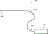
Fig. 1A is a block diagram depicting an example embodiment of a delivery system.
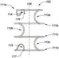
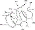
Fig. 1B, 1C, and 1D are side, end, and perspective views, respectively, depicting an example embodiment of an implant.
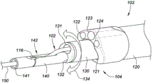
Fig. 2A-2H are perspective views depicting an example embodiment of a delivery system in different stages of deployment of an implant.
Fig. 3A-3C are perspective views depicting example embodiments of a gripper component for use within a delivery system.
Fig. 4A-4J are partial cross-sectional views depicting example embodiments of an anchor delivery element of a delivery system.
Fig. 5A-5B are side views depicting an example embodiment of the delivery system in various stages of deployment of the implant.
Fig. 6A and 6B are internal side and perspective views, respectively, depicting an example embodiment of a proximal control device.
Fig. 6C is a perspective view depicting an exemplary embodiment of a gear for use with the delivery system.
Fig. 7A is an internal top view depicting an example embodiment of components of a proximal control device.
Fig. 7B is a perspective view depicting an example embodiment of a cam.
FIG. 8 is an interior side view depicting an example embodiment of a gear assembly.
9A-9F are internal perspective views depicting an example embodiment of components of a proximal control device.
Fig. 10A is a flow chart depicting an example embodiment of a method for delivering an implant.
Fig. 10B is a timing diagram depicting an example embodiment of a sequence of steps for deploying an implant.
11A-12C are perspective views depicting example embodiments of components within a proximal control device.
12D-12E are perspective views depicting example embodiments of a distal end region of an outer tubular member.
Fig. 13 is an exemplary cross-sectional view of a male anatomy.
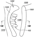
Fig. 14A is an example cross-sectional view of a male anatomy with an example embodiment of an implant deployed therein.
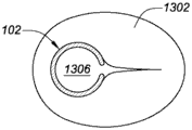
Fig. 14B is an example cross-sectional view of the male anatomy, and fig. 14C is an example cross-sectional view of the male anatomy taken along line 14C-14C of fig. 14B.
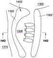
Fig. 14D is an example cross-sectional view of a male anatomy with an example embodiment of an implant deployed therein, and fig. 14E is an example cross-sectional view of the male anatomy taken along line 14E-14E of fig. 14D.
Fig. 14F is an example cross-sectional view of a male anatomy with an example embodiment of an implant deployed therein, and fig. 14G is an example cross-sectional view of the male anatomy taken along line 14F-14F of fig. 14G.
Detailed Description
Before the present subject matter is described in detail, it is to be understood that this disclosure is not limited to particular embodiments described, as such may, of course, vary. It is also to be understood that the terminology used herein is for the purpose of describing particular embodiments only, and is not intended to be limiting, since the scope of the present disclosure will be limited only by the appended claims.
The subject matter presented herein is described in the context of delivering or deploying one or more implants within the prostatic urethra. The purpose for deploying the implant(s) in the prostatic urethra can vary. The embodiments described herein are particularly suitable for treating BPH, but are not so limited. Other situations in which these embodiments may be used include, but are not limited to, treatment of obstructions caused by prostate cancer, bladder cancer, urinary tract injury, prostatitis, dyssynergia of the sphincter vesicae, and/or benign or malignant urethral strictures. Further, these embodiments may have applicability for deploying one or more implants in the urinary tract or other locations in the bladder, as well as in other biological cavities, or spaces, such as the human vasculature, heart system, lung system, or gastrointestinal tract, including locations within the heart, stomach, intestines, liver, spleen, pancreas, and kidneys.
Fig. 1A is a block diagram depicting an example embodiment of a delivery system 100, the delivery system 100 having an elongate delivery device 103, the elongate delivery device 103 coupled with a proximal control device 200. The distal end region 104 is adapted for insertion through the urethral opening into the patient's urethra (or other cavity or body cavity of the patient). The distal end region 104 preferably has an atraumatic configuration (e.g., relatively soft and rounded) to minimize irritation or trauma to the patient. The elongate delivery device 103 carries or houses one or more implants 102 (not shown) to be delivered or deployed within or adjacent to the prostatic urethra. The proximal end region 105 of the delivery device 103 is coupled with a proximal control device 200, which proximal control device 200 remains outside the patient's body and is configured to be used by a physician or other medical professional to control the delivery of one or more implants 102.
Example embodiments of a delivery device and related methods.
Fig. 1B, 1C, and 1D are side, end, and perspective views, respectively, depicting an example embodiment of the implant 102 in a rest configuration. The implantable device 102 is biased toward a rest configuration depicted herein, and is deformable between the rest configuration and a relatively more elongated receiving (or delivery) configuration (e.g., see fig. 3A) for receiving the implant 102 within the delivery device 103. The containment configuration may be a straight or linear state with minimal curvature. The rest configuration has a relatively larger transverse width and a relatively shorter longitudinal length than the receiving configuration. When exiting the open end of the delivery device 103, the implant 102 is free to transition its shape back to the shape of the at rest configuration, although the constraints imposed by the patient's urethral wall may prevent the implant 102 from fully reaching the at rest configuration. Because the implant 102 is biased toward the resting configuration, the implant 102 is configured to automatically expand when unconstrained by the delivery device 103, and may be referred to as "self-expanding. For example, the shape of the implant 102 in its deployed state within the patient's urethra may be referred to as the deployed configuration, and will generally be the shape deformed from the resting configuration due to the surrounding tissue, although the deployed configuration may be the same as the resting configuration.
The implant 102 may be configured in a number of different ways, including any and all of those implant configurations described in U.S. patent publication No. 20150257908 and/or international publication No. WO2017/184887, both of which are incorporated herein by reference for all purposes.
The implant 102 may be formed from one or more separate bodies (e.g., wires, ribbons, tubular members) having different geometries. Referring to the embodiment of fig. 1B-1D, the implant 102 has a main body formed from only one single wire member provided in a predetermined shape. The implant 102 may have two or more ring structures 111 (in this embodiment, there are four: 111a, 111b, 111c, and 111 d) with one or more interconnects 112 extending between each adjacent pair of ring structures 111 (in this embodiment, there is one interconnect between each adjacent pair, for a total of three interconnects: 112a, 112b, and 112 c). Each interconnect 112 extends from one ring structure 111 to a closely adjacent ring structure 111. Each interconnect 112 may have a relatively straight shape (not shown) or a curved (e.g., semi-circular or semi-elliptical) shape, as shown in fig. 1B-1D.
The loop structure 111 is configured to maintain the urethra in a fully or partially open state when expanded from the containment configuration. The device 100 can be manufactured in a variety of sizes as desired, such that the width (e.g., diameter) of each loop structure 111 is slightly greater than the width of the urethra, and the length of each interconnection 112 determines the spacing between the loop structures 111. The annular structures 111 may have the same or different widths. For example, in the embodiment described herein, annular structure 111a has a relatively smaller width than structures 111b-111d, which structures 111b-111d have the same width. This accommodates the prostatic urethra converging to a smaller geometry in front of the bladder neck.
Each annular structure 111 may lie or lie in a single plane, and in some embodiments, the single plane may be oriented to have an orthogonal axis (as depicted in fig. 1B) that is perpendicular to the central axis 124 of the implant 102. In other embodiments, the ring structure 111 may lie in multiple planes. The ring-shaped structure 111 may extend about the central axis 126 to form a complete circle (e.g., 360 degrees of rotation), or may form less than a complete circle (e.g., less than 360 degrees), as shown herein. Although not limited thereto, in many embodiments, the ring structure 111 extends between 270 degrees and 360 degrees.
As can be seen in fig. 1B-1D, the geometry of the implant 102 may have a cylindrical or substantially cylindrical profile shape with a circular or elliptical cross-section. In other embodiments, the implant 102 may have a prismatic or substantially prismatic shape, have a triangular or substantially triangular cross-section, or have other shapes.
The implant 102 may also include a distal engagement member 114 and a proximal engagement member 115, each configured to engage with an element of the delivery device 103. Engagement with the delivery device 103 may serve one or more purposes, such as allowing for controlled release of the implant 102, allowing the ends of the implant 102 to move relative to one another, and/or allowing for retrieval of the implant 102 after deployment, for example, in situations where a physician wishes to recapture the implant 102 and redeploy the implant 102 in a different position. In this embodiment, the distal engagement member 114 is a wire-like extension from the annular structure 111a having a curved (e.g., S-like) shape for positioning the atraumatic end 116 (e.g., rounded, spherical, balled) in a position suitable for engagement with the delivery device 103 and thereby allowing control of the distal end region of the implant 102. Similarly, the proximal engagement member 115 has a curved shape for positioning the further atraumatic end 117 in a position suitable for engagement with the delivery device 103 and thereby allowing control of the proximal end region of the implant 102. In other embodiments, the distal and proximal engagement members 114, 115 may be omitted, and the delivery device 103 may be coupled with the implant 102 at one or more other distal and/or proximal locations, such as on the annular structure 111 or the interconnect 112.
The delivery device 103 may include one or more elongate flexible members (e.g., 120, 130, 140, and 150 as described below), each having one or more internal lumens. The one or more elongate flexible members of the delivery device 103 may be solid or non-hollow members without an internal lumen. Fig. 2A is a perspective view depicting an example embodiment of the distal end region 104 of the delivery device 103. In this embodiment, the delivery device 103 comprises a first elongate tubular member 120, a second elongate tubular member 130, a third elongate tubular member 140 and a fourth elongate tubular member 150. The delivery device 103 can vary, and in other embodiments, more or fewer tubular members can be included.
In this embodiment, the first elongate tubular member 120 is the outermost tubular member and is flexible, yet provides support for the members contained therein. The first tubular member 120 is referred to herein as the outer shaft 120 and may have one or more internal lumens. In this embodiment, the outer shaft 120 includes a first inner cavity 121 that houses a second elongate tubular member 130, which second elongate tubular member 130 is referred to herein as the inner shaft 130. The outer shaft 120 and the inner shaft 130 may each be controlled independently of each other. Inner shaft 130 is slidable distally and proximally within lumen 121 and is shown here as partially extending from the open distal terminal end of outer shaft 120.
In this embodiment, the outer shaft 120 includes three additional cavities 122, 123, and 124. The illumination device (not shown) and the imaging device (not shown) may be housed in two of the cavities 122 and 124 (e.g., cavities 122 and 123). The imaging device may utilize any desired type of imaging modality, such as optical or ultrasound imaging. In one example embodiment, the imaging device utilizes a forward (distal) view CMOS imager. The illumination device may be configured to provide sufficient illumination for optical imaging and, in one embodiment, includes one or more Light Emitting Diodes (LEDs). In embodiments where illumination is not required, such as for ultrasound imaging, the illumination device and its corresponding cavity may be omitted. The illumination and/or imaging devices may each be fixedly secured at the distal terminal ends of lumens 122 and 123, or may each be slidable within lumens 122 and 123 to allow further distal advancement from outer shaft 120, and/or retraction into outer shaft 120. In one exemplary embodiment, the illumination device and the imaging device are mounted together and there is only a single cavity 122 or 123 for this purpose. Other lumens (e.g., lumen 124) may be configured as irrigation or irrigation ports from which a fluid (such as saline) may be introduced into the urethra to irrigate the region and provide sufficient fluid through which to image the implant 102 and the surrounding prostatic urethral wall.
The outer shaft 120 has a proximal end (not shown) that couples with the proximal control device 200. The delivery device 103 may be configured to be steerable to navigate tortuous anatomy. The steerability may be unidirectional (e.g., using a single puller wire) or multidirectional (e.g., using two or more puller wires arranged at different radial positions around the device 103) as desired for the application. In some embodiments, a structure for steering (e.g., a pull wire) extends from the distal end region 104 of the delivery device 103 (e.g., a plate or other structure in which the distal end of the pull wire is secured within the distal end region 104) to the proximal control device 200, where it can be manipulated by a user to steer the delivery device 103. The steering structures may be located in one or more cavities of the outer shaft 120, or may be coupled to a sidewall of the outer shaft 120, or embedded within a sidewall of the outer shaft 120. The delivery device 103 may be biased to deflect (e.g., bend) in a particular lateral direction such that the device 103 automatically deflects in this manner, and the force applied to deflect the delivery device 103 opposes this biased deflection. Other mechanisms for steering the delivery device 103 may also be used. The steering mechanism may also be locked or adjusted during deployment of the implant 102 to control the position of the implant 102 within the anatomy (e.g., forward steering may help place the implant 102 in a more desired anterior position during deployment).
The inner shaft 130 can include one or more inner lumens for accommodating one or more implants 102 and/or other components. In this embodiment, the inner shaft 130 includes a first inner lumen 131 in which one or more implants 102 can be housed and a second inner lumen 132 in which a third elongate tubular member 140 can be housed. In this embodiment, the third elongate tubular member 140 is configured to releasably couple with a distal end region of the implant 102 and is referred to as a distal control member or tether 140. Distal control member 140 can be slidably advanced and/or retracted relative to inner shaft 130. The distal control member 140 may include an inner lumen 141 housing a fourth elongate tubular member 150, the fourth elongate tubular member 150 being shown here as extending from an open distal terminal end of the distal control member 140. The fourth elongate tubular member 150 is configured to anchor the delivery device 103 relative to the anatomy of the patient, e.g., to hold components of the delivery device 103 stationary relative to the anatomy during deployment of the implant 102, and is referred to as the anchor delivery member 150.
In the configuration depicted in fig. 2A, anchor delivery member 150 extends from lumen 141 of distal control member 140, and distal control member 140 is shown extending from lumen 121 of outer shaft 120 along with inner shaft 130. As the delivery device 130 is advanced through the urethra, the anchor delivery member 150 is preferably fully contained within the distal control member 140, and the distal control member 140 is retracted with the inner shaft 130 from the position shown in fig. 2A such that they are within the cavity 121 of the outer shaft 120 and do not extend from the open distal terminal end of the cavity 120. In other words, in some embodiments, the open distal termination of the outer shaft 120 forms the distal-most structure of the device 103 when initially advanced through the urethra. This facilitates steering of the delivery device 103 by the outer shaft 120. The physician may advance the distal end region 104 of the delivery device 103 near the desired implantation site, or completely into the bladder of the patient. The delivery member 150 may be exposed from the open distal terminus of the distal control member 140 by advancing the anchor delivery member 150 further distally into the bladder, or if already present within the bladder, by proximally retracting the other component anchors of the delivery device 103. At this point, the anchors from the anchor delivery member 150 can be deployed in the bladder.
The placement of these components within the system 100 is not limited to the embodiment described with respect to fig. 2A. In some embodiments, the outer shaft 120 may be omitted entirely. In such embodiments, visualization of the deployment procedure may be accomplished by external imaging (such as fluoroscopy), wherein the implant 102 and delivery device 103 may be radiopaque or may include radiopaque markers, and wherein the imaging and illumination cavities 122, 123 (and imaging and illumination devices) and irrigation cavities are omitted. In some embodiments, the distal control member 140 can be slidable within a lumen of the outer shaft 120 (the same lumen that receives the inner shaft 130 or a different lumen) as opposed to the distal control member 140 being slidably received within the inner shaft 130. Similarly, the anchor delivery member 150 can be slidable within a lumen of the outer shaft 120 (the same lumen or a different lumen that receives the inner shaft 130 and/or the anchor delivery member 150) or within a lumen of the inner shaft 130 (the same lumen or a different lumen that receives the distal control member 140) as opposed to the anchor delivery member 150 being slidably received within the distal control member 140. In some embodiments, the outer shaft 130 has a separate and distinct cavity for each of the members 130, 140, and 150, and can be configured to deploy the implant 102 around the members 140 and 150.
Fig. 2B is a perspective view depicting the distal end region 104 of the delivery device 103, with various components deployed. In this embodiment, the anchor delivery member 150 includes an anchor 152 in the form of an inflatable member or balloon. Other embodiments of the anchor 152 are described with respect to fig. 4A-4G. The anchor 152 expands (or otherwise transitions) to a size greater than the bladder neck size such that the anchor 152 resists proximal retraction (e.g., a relatively light tension). In embodiments in which the anchors 152 are balloons, the balloons may be elastic or inelastic, and are inflatable with an inflation medium (e.g., air or a liquid, such as saline) introduced into the balloon 152 through one or more inflation ports 153. Here, three inflation ports 153 are located on the shaft of the anchor delivery member 150 and communicate with an inflation lumen that extends proximally back to the proximal control device 200, which proximal control device 200 may include ports for inflation with a syringe. Upon deployment of the anchor 152, the physician may retract the delivery system 100 proximally until the anchor 152 contacts the bladder neck and/or wall (if not already contacting).
The physician can use the imaging means of the outer shaft 120 to move the delivery device 103 proximally away from the anchor 152 until the physician is in the desired position within the urethra to begin deployment of the implant 102. A retainer 142 on the distal control member 140 is releasably coupled with the distal engagement member 114 of the implant 102. The physician can position the retaining element 142 in a position along the length of the urethra where the physician desires to deploy the distal end of the implant 102. This can involve moving the distal control member 140 and the inner shaft 130 together proximally and/or distally relative to the anchor delivery member 150. In another embodiment, the position of the retainer 142 is fixed relative to the anchor 152 such that the longitudinal position of the implant 102 within the anatomy is set by the system independent of any manipulation by the physician. The coupling of the distal engagement member 114 and the retainer 142 also allows the physician to manipulate the radial orientation of the implant 102 by rotating the distal control member 140 and the inner shaft 130 together. Active or passive shaping of the distal control member 140 may allow for more desirable placement of the implant 102. For example, member 140 can have a curvature that places the implant in a more anterior anatomical location. This curvature may be inherently provided in the member 150 or may be actively applied by the physician through a separate entity, such as a control wire. Once in the desired position and orientation, the physician can retract the inner shaft 130 proximally relative to the distal control member 140 to begin deployment of the implant 102.
To assist in deployment, the inner shaft 130 can be rotated clockwise and counterclockwise (as depicted by arrow 134) about the distal control member 140. Referring again to fig. 1B-1C, the implant 102 has a non-constant winding direction that proceeds clockwise along the loop structure 111a, then reverses to a counterclockwise direction for loop structure 111B along the interconnect 112a, then reverses to a clockwise direction for loop structure 111C along the interconnect 112B, and then reverses to a counterclockwise direction for loop structure 111d along the interconnect 112C until terminating at the proximal engagement member 115, when viewed starting at the distal engagement member 114. Depending on the winding direction of the portion of the implant 102 that is about to exit the open distal terminal end of the cavity 131, the transition of the implant 102 toward the resting configuration may exert a torque on the shaft 130 if the shaft 130 is not actively rotating as the implant 102 is deployed. This torque may cause the shaft 130 to passively rotate clockwise or counterclockwise, respectively (without user intervention). In certain embodiments described elsewhere herein, the shaft 130 actively rotates during deployment. Rotation of the inner shaft 130 relative to the distal control member 140 thus allows the delivery device 103 to rotate and follow the winding direction of the implant 102. In some embodiments, all of the annular structures 111 are wound clockwise or counterclockwise in the same direction (e.g., as in the case of a full helical or spiral implant), or do not have a set winding direction.
In this or other embodiments, the distal end region of the inner shaft 130 is configured to be relatively more flexible than the more proximal portion of the inner shaft 130, which can allow for avoiding excessive movement of the rest of the device 103 during deployment, resulting in better visualization and less tissue contact by the device 103. Such a configuration may also reduce the stress exerted by the device 103 on the implant 102 during delivery. For example, the portion of the inner shaft 130 extending from the outer shaft 120 during deployment may be relatively more flexible than the portion of the inner shaft 130 remaining within the outer shaft 120, thus allowing the inner shaft 130 to flex more easily as the implant 102 exits the inner cavity 131. This in turn may stabilize the delivery device 103 and allow the physician to obtain a stable image of the scheduled procedure.
Fig. 2B depicts the implant 102 after the three loop structures 111a, 111B, and 111c have been deployed. The shaft 130 continues to retract proximally until the entire implant 102, or at least all of the ring structure 111, has exited the cavity 131. If the physician is satisfied with the deployed position of the implant 102 and the deployed shape of the implant 102, the implant 102 can be released from the delivery device 103.
Release of the distal end of the implant 102 may be accomplished by releasing the retainer 142. The retainer 142 may be a cylindrical structure or other sleeve that is linearly or rotationally actuated over the cavity or recess in which the portion of the implant 102 is received. In the embodiment of fig. 2B, retainer 142 includes an opening or slit that allows distal engaging member 114 to pass therethrough. Holder 142 can be rotated relative to the cavity or recess in which distal engaging member 114 (not shown) is received until the opening or slit is positioned over member 114, at which point member 114 can be freely released from distal control member 130. Rotation of holder 142 may be accomplished by rotation of a rotatable shaft, rod, or other member coupled to holder 142 (and accessible at proximal control device 200).
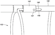
Fig. 2C and 2D are perspective views depicting another example embodiment of the system 100, wherein different embodiments of the retainer 142 are shown in greater detail. Here, holder 142 slides distally and/or proximally relative to distal control member 140. The distal engagement member 114 of the implant 102 may be received within a corresponding recess of the distal control member 140. Retainer 142 can be slid over distal engagement member 114 while being received within this recess until retainer 142 abuts the stepped portion of member 140. The control wire 146 extends within the length of the control member 140, either in the same lumen as the anchor delivery member 150 or in a different lumen. A control line 146 is coupled to the holder 142 having an enlarged portion 147 from which the control line 146 may be routed into the member 140 through an opening 148.
The engagement member 114 can be placed within the recess and the retainer 142 can be advanced over the engagement 114 to secure the distal end of the implant 102 to the control member 140. When the implant 102 is satisfactorily deployed within the urethra, for example, in the state of fig. 2C, the holder 142 can be retracted proximally with the control wire 146 to expose the engaging member 114 and allow the engaging member 114 to be released from the member 140. Fig. 2E and 2F are perspective views depicting another embodiment of the system 100, with another configuration for the holder 142, the holder 142 operating in a manner similar to that described with respect to fig. 2C and 2D. Here, the implant 102 is not shown, and the recess 143 in which the distal engagement member 114 may be received is shown in more detail.
Fig. 2G and 2H are side and perspective views, respectively, of another exemplary embodiment of the system 100. In this embodiment, the inner shaft 130 includes a flexible distal extension 160, with an inner lumen 131 (not shown) located in the flexible distal extension 160. In this configuration, the open distal terminal end of the cavity 131 is distal to the open distal terminal end (not shown) of the cavity 132, and the distal control member 140 extends from the cavity 132. Lumens 122, 123 and 124 (not shown) are located on outer shaft 120 opposite distal extension 160. The flexible distal extension 160 facilitates flexibility to stabilize the delivery system and to stabilize the image. The flexible extensions 160 help align the annular structure 111 in a planar manner and help guide the implant 102 (e.g., radially directed) toward the urethral wall during deployment.
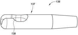
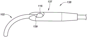
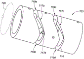
The proximal end of the release implant 102 is also controllable. Fig. 3A is a partial cross-sectional view depicting an example embodiment of the system 100, wherein a portion of the implant 102 is shown within the inner cavity 131 of the inner shaft 130. Here, the implant 102 is in a linear state prior to deployment, wherein the proximal engagement member 115 is coupled with a grip 136, said grip 136 being distally and/or proximally slidable within the cavity 131. The grip 136 may include a distal end region 137 on or coupled with a shaft 138. The grip 136 is preferably controllable to rotate and longitudinally translate (e.g., push and pull) the implant 102 relative to the inner shaft 130.
Fig. 3B and 3C are perspective views depicting example embodiments of the distal end region 137 without the implant 102 and with the grip 136 of the implant 102, respectively. The catch 136 includes a recess (also referred to as a cavity or pocket) 139 for receiving and retaining the proximal engagement member 115. Here, the enlarged portion 117 is retained within the recess 139 by a distal necked down region having a relatively smaller width. When within the inner cavity 131, the sidewall of the inner shaft 130 maintains the proximal engagement member 115 within the recess 139. When the distal end region 137 exits the inner lumen 131 (either by retraction of the inner shaft 130 relative to the catch 136, or by advancement of the catch 136 relative to the inner shaft 130), there is no longer constraint imposed by the inner shaft sidewall, and the engagement member 115 is free to release from the catch 136. Thus, when the surgeon is satisfied with the placement of the deployed implant 102, distal engagement member 114 can be released by moving holder 142 and allowing distal engagement member 114 to decouple from control member 140, and proximal engagement member 115 can be released by exposing grip 136 from within inner shaft 130 and allowing proximal engagement member 115 to decouple from grip 136.
The grip 136 may also assist in loading the implant 102. In some embodiments, the tension exerted on the implant 102 by the grip 136 (while the opposite end of the implant 102 is secured, for example, by the retainer 142) facilitates transitioning of the implant 102 from the resting configuration to a linear configuration suitable for insertion of the implant 102 into the inner shaft 130.
The anchor delivery members 150 can have a variety of different configurations and geometries (e.g., including those that extend across the bladder wall in one direction, extend across the bladder wall in two directions (e.g., left and right), or extend across the bladder wall in three or more directions). Fig. 4A-4B are cross-sectional views depicting an example embodiment of an anchor delivery member 150 in multiple stages of deployment within a patient. In fig. 4A, the anchor delivery member 150 has been advanced through the urethra 401 until the open distal end 151 passes the bladder neck and is within the bladder 402, although in this and other embodiments, the end 401 can stop before entering the bladder 402. Here, two anchor arms 408a and 408b are housed within the inner cavity of the anchor delivery member 150. In other embodiments, the anchor arms 408 may each be received in a separate cavity within the member 150. The anchor arm 408 may be advanced distally relative to the anchor delivery member 150 (or the anchor delivery member 150 may be advanced into the bladder 402 and retracted proximally relative to the anchor arm 408) such that upon exiting the open distal end 151, the deflectable portions 410a and 410B are laterally transitioned into contact with the bladder wall, forming the anchor 152, as depicted in fig. 4B.
The anchor arms 408 may be formed of a shape re-tensioning material that is biased toward the rest configuration of fig. 4B. The distal ends of the anchoring arms 408 may each have an atraumatic termination (e.g., rounded, spherical, bulbous), as depicted herein, and or alternatively, the distal ends of the arms 408 may be bent away from the bladder wall for increased atraumatic effect. In other embodiments, only one anchoring arm 408 is used. Fig. 4C is a cross-sectional view depicting another example embodiment of an anchor delivery member 150. Here, deflectable portions 410a and 410b have a generally straight or linear shape and are deflected from a common shaft 412, which shaft 412 is distally and/or proximally slidable relative to anchor delivery member 150. In all of the anchoring embodiments described herein, the one or more deflectable portions may deflect from a common axis (such as depicted herein) or from a separate axis (such as depicted in fig. 4A-4B).
Fig. 4D-4E are partial cross-sectional views depicting another example embodiment of an anchor delivery member 150. Fig. 4D depicts this embodiment, with the anchor 152 in a partially deployed state from the open distal end 151 of the anchor delivery member 150. Fig. 4E depicts the anchor 152 after full deployment within the bladder 402. Here, anchor 152 includes laterally deflectable struts 420a, 420b, 421a, and 421b connected by hinges 422a, 422b, and 422 c. Specifically, laterally deflectable struts 420a and 421a are connected by hinge 422a, laterally deflectable struts 420b and 421b are connected by hinge 422b, and struts 421a and 421b are connected by hinge 422 c. Again, the anchor 152 is biased toward the rest configuration depicted in fig. 4E, and automatically transitions toward this configuration once exposed from within the inner cavity of the anchor delivery member 150. The hinges 422 may each be implemented as a living hinge, such as depicted in fig. 4E, for example, defined by a reduced or relatively more flexible section of the device. Other hinge configurations may also be utilized.
In another embodiment, a pull wire or other member 424 is attached to one or more of the struts 421 and/or hinges 422c and extends proximally to the proximal control device 200. In fig. 4E, the pulling member 424 is shown in phantom to indicate that it is optional. Proximal retraction of the pulling member 424 at the proximal control device 200 causes the structural arrangement to deflect laterally into the configuration depicted in fig. 4E. This arrangement provides a significant locking force while maintaining tension on the pulling member 424.
Fig. 4F is a partial cross-sectional view depicting another example embodiment of an anchor delivery member 150. Here, the shape re-tensioning element 430 has been advanced from within the inner lumen of the anchor delivery member 150, where it is a relatively straight or linear shape. Upon exiting the open distal end 151, the distal portion of the element 430 automatically transitions toward a laterally expanded shape 432, which laterally expanded shape 432 is in this embodiment in the shape of a coil or spiral. Fig. 4G depicts another example embodiment, wherein the laterally expanded shape 432 has a plurality of loops and resembles the number "8" or bow tie. Many different shapes may be used for the laterally expanded shape 432 in addition to the shapes depicted herein. In all anchoring embodiments, the distal end of the wire or element exposed to the body tissue may have a rounded or enlarged atraumatic end (as depicted in fig. 4F and 4G).
Upon completion of the implant deployment procedure, the anchors 152 can be collapsed or retracted to allow removal of the delivery device 103. For example, in embodiments in which the anchor 152 is a balloon, the balloon is deflated and optionally retracted back into the cavity of the device 103 and then withdrawn from the bladder and urethra. In embodiments in which the anchors 152 are in the form of a wire or other expandable member (such as those described with respect to fig. 4A-4G), the anchors 152 are retracted back into the lumen of the device 103 (from which they were previously deployed), and the device 103 may then be withdrawn from the bladder and urethra. Retraction may be accomplished using fluid or pneumatic actuation, a threaded mechanism, or otherwise.
In fig. 2B, anchor 152 is a generally spherical balloon with anchor delivery member 150 extending through the center. In other embodiments, the balloon anchor 152 may be laterally offset, or positioned on only one side of the anchor delivery member 150. Fig. 4H is a partial cross-sectional view depicting an example embodiment of balloon 152 having a lateral offset. Here, the laterally offset balloon 152 exerts a force on the side of the bladder neck 403 and forces the anchor delivery member 150 (and delivery device 103) in direction 450.
In other embodiments, the device 103 may include two or more balloons that may be independently inflated in different lateral directions. Independent inflation of one or more balloons and maintaining one or more remaining balloons in a deflated state can allow a user to change the angle of the delivery catheter relative to the anatomy, and thereby allow the implant to deploy in an anatomy with significant curvature. Fig. 4I depicts another example embodiment, wherein the first anchoring balloon 125a is inflated to a larger size than the second anchoring balloon 152b on the opposite side of the member 150. Member 150 tilts in direction 451 away from smaller balloon 152b due to the force exerted on the bladder wall. The process of selecting the appropriate balloon or balloons for inflation can be performed by the physician, and the inflation and deflation can be repeated until the physician achieves the desired angular orientation of the device 103 within the anatomy, at which point the remainder of the delivery process can be performed. The delivery member 150 may be a preformed flexible or rigid shaft such that it will not interfere with the ability of the implant 102 to be placed in the desired anatomical location. For example, the curvature in the member 150 just proximal of the balloon installation location may allow the implant 102 to be placed more anteriorly, without being constrained by the bladder neck.
In some embodiments, the shaped balloon or substantially elastic balloon may be inflated at the same location as the bladder neck. Fig. 4J depicts an exemplary embodiment in which balloon 152 is inflated at bladder neck 403. Here, balloon 152 includes a first lobe 155 formed in bladder 402 and a second lobe 156 formed in urethra 401. This configuration may be used to anchor the member 150 directly over the bladder neck 403.
Example embodiments of proximal control devices and related methods.
Fig. 5A is a side view depicting an example embodiment of the delivery system 100 prior to deployment of the implant 102; and fig. 5B is a side view depicting this embodiment with the implant 102 in the deployed configuration (the anchor delivery member 150 and the distal control member 140 are not shown). In this embodiment, the proximal control device 200 is a handheld device having a handle 201, a first user actuator 202 (configured as a trigger in this example), a main body 203, and a second user actuator 205. The longitudinal axis of the delivery device 103 is indicated by dashed line 204. Proximal control device 200 may include a mechanism that is manually driven by actuation of actuator 202 to cause relative movement of the components of device 103. In other embodiments, instead, the proximal control device 200 may utilize a motorized mechanism. The second user actuator 205 may be configured to control the steering of the delivery device 103. Here, the actuator 205 is configured as a rotatable wheel that can wind or unwind a pull wire (not shown) within the delivery device 103 and cause the device 103 to deflect up and down, as shown herein.
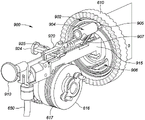
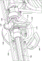
Fig. 6A is an internal view of the proximal control device 200 depicting various mechanical components or subassemblies within the main housing 203 of the control device 200. In this embodiment, the proximal control 200 is configured to perform three types of movement on the implant 102, namely distal advancement (e.g., pushing) of the implant 102 along the axis 204, proximal retraction (e.g., pulling) of the implant 102 and/or the inner shaft 130 along the axis 204, and rotation (e.g., rotating) of the inner shaft 130 about the axis 204. In other embodiments, the proximal control device 200 may be configured to perform any subset of one or both of the aforementioned types of motions, perform these types of motions but be assigned to different components, or perform other types of motions not mentioned herein, depending on the desired delivery function.
In this embodiment, the proximal control device 200 comprises a longitudinally translatable member 601, said member 601 being configured as a yoke in this embodiment. Yoke 601 is coupled to trigger 202 such that depression of trigger 202 results in proximal longitudinal translation of yoke 601. Yoke 601 is coupled to two proximally located ratchet members 602 and 603, which ratchet members 602 and 603 are configured as pawls in this embodiment. The pawl 602 has a set of teeth that oppose corresponding teeth on the pawl 603, and the teeth of each pawl 602 and 603 can interface or engage with complementary teeth on a gear 605 (see fig. 6B), which gear 605 is referred to herein as a pinion gear that is part of the first gear assembly 600.
The user can access the switch 604 and can switch the switch 604 between two positions, wherein each position is responsible for engaging only one of the jaws 602 and 603 with the pinion 605. Each of the jaws 602 and 603 is deflectable and biased (e.g., with a spring) toward engagement with the pinion 605. In this embodiment, placing the shifter 604 in the down position moves the pawl 602 out of engagement with the pinion 605 and moves the pawl 603 into engagement with the pinion 605. Proximal movement of the yoke 601 and jaws 603 causes the pinion 605 to rotate counterclockwise. Placing the shifter 604 in the up position reverses the engagement and places the pawl 602 in engagement with the pinion 605, and proximal movement of the yoke 601 and pawl 602 causes the pinion 605 to rotate clockwise.
In this embodiment, the first gear assembly 600 includes a pinion 605, a second gear 610, a third gear 612, and a fourth gear 614. In other embodiments, the first gear assembly 600 may be implemented to perform the same or similar functions using more or fewer gears than those described herein.
The pinion 605 is engaged with a second gear 610, the second gear 610 being oriented perpendicular to the pinion 605. The pinion 605 has teeth protruding from a radial edge of the gear 605, while the second gear 610 has teeth protruding from both a distal face and a proximal face of the gear 610, the second gear 610 being referred to herein as a face gear 610. Counterclockwise rotation of the pinion 605 will cause the face gear 610 to rotate in a first direction, and clockwise rotation of the pinion 605 will cause the face gear 610 to rotate in a second, opposite direction. The direction of rotation of the face gear 610, in turn, determines whether the implant 102 is proximally retracted or distally advanced relative to the housing 203.
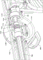
Fig. 6B is a perspective view depicting the interior of this embodiment of the proximal control device 200 in more detail. Proximally facing teeth on face gear 610 engage teeth on gear 612, which gear 612 is referred to as the input gear. The teeth of input gear 612 engage the teeth of gear 614. The gear 614 is coupled or integrated with a spool 616, the spool 616 configured to receive or retain the gripper shaft 138. As can be seen in the embodiment of fig. 9A-9B, the spool 616 can include an optional groove or channel 617 in which the gripper shaft 138 can be received. Depending on the direction of rotation, rotation of the spool 616 causes the gripper shaft 138 to wind onto the spool 616 or unwind from the spool 616. Winding of the grip shaft 138 onto the reel 616 corresponds to proximal retraction of the implant 102 (e.g., into the inner shaft cavity 131), while unwinding of the grip shaft 138 from the reel 616 corresponds to distal advancement of the implant 102 (e.g., out of the inner shaft cavity 131). In the embodiment of fig. 9A-9B, the channel 617 is a convoluted channel that extends around the circumference of the spool 616 a plurality of times. In the embodiment depicted in fig. 6B, the channel 617 is omitted.
In some embodiments, the input gear 612 may be configured as an interrupted gear, wherein one or more teeth are not present, such that rotation of the input gear 612 will not always result in a corresponding rotation of another gear. An example of such an input gear 612 is depicted in the perspective view of fig. 6C. According to the angles depicted herein, the input gear 612 has teeth 620 spaced at regular intervals on the left side 621 of the radial edge of the gear. Teeth 620 are also present at regular intervals on the right side 622 of the radial edge of the gear, except for the area 623 where no teeth are present. A smooth-surfaced hub 624 exists adjacent this interruption zone 623. The right side 622 of the input gear 612 is configured to engage the spool gear 614. The placement of the interruption region 623 is predetermined such that continued depression of the trigger 202 by the user (and thus continued rotation of the pinion 605, face gear 610, and input gear 612) does not translate into continued rotation of the spool gear 614. Conversely, cord reel gear 614 may be rotated only when engaged with the portion of input gear 612 having teeth 620, and spool gear 614 may not be rotated when interrupting area 623 traverses cord reel gear 614. The placement of the interruption region 623 allows for a pause in the longitudinal translation (e.g., distal and/or proximal) of the gripper shaft 138. The interruption zone 623 is specifically positioned such that longitudinal translation occurs only during certain portions of the delivery sequence.
In this embodiment, placing the transducer 604 in the down position translates user depression of the trigger 202 into pushing the implant 102, while placing the transducer 604 in the up position translates user depression of the trigger 202 into pulling the implant 102 and/or the inner shaft 130. In other embodiments, the transducer positions may be reversed to cause the opposite motion.
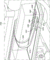
Fig. 7A is a top view depicting the cam assembly 702 of the proximal control device 200. The cam assembly 702 includes an outer slit tube or cam 703, an inner slit tube 704, and a guide member 706. The cam assembly may be positioned within the yoke 601. Fig. 7B is a perspective view depicting this embodiment of the cam 703. Cam 703 is coupled to face gear 610 such that rotation of face gear 610 also rotates cam 703. The inner slit tube 704 is mounted within the proximal control device 200 such that the inner slit tube 704 does not rotate when the cam 703 is rotated. The guide member 706 may be configured as an arm or strut member, the guide member 706 being located within both the slot 710 in the cam 703 and the slot 714 in the inner tube 704 and following both the slot 710 in the cam 703 and the slot 714 in the inner tube 704. The guide member 706 is coupled with a hub 802 (fig. 8) located within the inner slit tube 704, which in turn is coupled with the inner shaft 130 (e.g., via a spindle, which in some embodiments may include a faceted shaft 708 and a rotational adapter 1112, as described with respect to fig. 11E). Rotation of the face gear 610 causes rotation of the cam 703, which in turn causes the guide member 706 to follow the path or course of the slot 710 in the cam 703. Because the guide member 706 extends through the slit 714 in the non-rotatable inner tube 704, rotation of the cam 703 causes the guide member 706 to move only in the longitudinal direction, not in the radial direction.
The slit 710 may have one or more slanted slit portions and/or one or more radial slit portions. In the embodiment described herein, slit 710 has a plurality of sloped portions (e.g., slit portions 717a, 717b, and 717 c) and a plurality of radial portions (e.g., slit portions 719a, 719b, 719c, and 719 d). Other shapes may be used and linked together to form the desired path. The slanted slit sections 717 may have a constant or variable slope, and in some embodiments, these slanted slit sections may vary such that the slope turns from positive to negative (similar to a "V").
The inclined slot portion 717 may be an opening or slot in the cam 703 having a non-perpendicular and non-parallel angle (relative to the longitudinal axis 204) that moves the guide member 706 along the longitudinal axis 204 during rotation. In most embodiments, radial slot portion 719 is parallel to longitudinal axis 204 such that rotation of cam 703 moves radial slot portion 719 relative to guide member 706 without guide member 706 moving in the longitudinal direction (proximal or distal). The radial slit portion 719 may correspond to a pause in the delivery sequence where the trigger 202 continues to be depressed and the other components of the delivery device 103 move, but the inner shaft 130 remains in the same relative position.
In fig. 7A, the guide member 706 is located at the distal-most terminal end within the radial slit portion 719a (fig. 7B). For retraction of the inner shaft 130, the cam 703 is rotated in the counterclockwise direction 720. When cam 703 rotates radial slot portion 719a beyond guide member 706, there is no longitudinal movement of inner shaft 130. When the guide member 706 reaches the inclined slit portion 717a, it begins to retract proximally with the inner shaft 130. This process repeats as the guide member 706 moves through the series of radial slot portions 719 (e.g., pauses in shaft 130 retraction) and angled slot portions 717 (e.g., shaft 130 retraction). In some embodiments, the guide member 706 is selectively coupleable with the outer shaft 120 to cause longitudinal movement of the component. For example, while the inner shaft 130 is retracted proximally, the outer shaft 120 may also be retracted proximally, e.g., to allow the physician to continue imaging the deployment procedure. (see, e.g., the description with respect to fig. 11A-11E.) a similar embodiment utilizing a cam assembly that can be used with the embodiments described herein is described in the incorporated international publication No. WO 2017/184887.
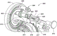
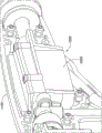
The proximal control apparatus 200 can also be configured to rotate the inner shaft 130 relative to the distal control member 140 during extrusion of the implant 102 from within the inner lumen 131. Fig. 8 is a side view depicting an example embodiment of a second gear assembly 800, the second gear assembly 800 configured to translate rotation of a face gear 610 into rotation of a hub 707, the hub 707 in turn coupled with an inner shaft 130, which in some embodiments is accomplished by way of an intermediate faceted shaft 708 (see, e.g., fig. 6A and 11A) and a rotational adapter 1104 (see, e.g., fig. 11E). The gear assembly 800 is located distal to the cam assembly 702 (see fig. 6A and 7A). The gear assembly 800 may include a first gear 802 coupled with a cam 703 such that rotation of the cam 703 causes rotation of the gear 802. In this embodiment, the gear 802 has an annular or ring-like shape with a first set of radially inwardly projecting teeth 804 and a discontinuity region 806. Gear 802 may have a second set of radially inwardly projecting teeth (not shown) with an interrupted region located in a different plane than teeth 804.
The gear assembly 800 may also include translating gears 810, 812, and 814, which may also be referred to as planetary gears, that translate the rotation of the gear 802 to a centrally located gear 816. In this example, the first set of teeth 804 is engaged with a gear 810, which gear 810 in turn is engaged with a sun gear 816 and rotates the sun gear 816 in a first direction. The sun gear 816 has a bore in which the hub 707 is rotationally secured, but free to slide longitudinally. Thus, rotation of the gear 802 translates into rotation of the hub 707, which in turn rotates the inner shaft 130. A second set of teeth (not shown) of gear 802 is engaged with gear 812, which gear 812 is in turn engaged with gear 814, which gear 814 is in turn engaged with sun gear 816 and rotates sun gear 816 in the opposite direction. Depending on the positioning of the first and second sets of teeth and the interruption regions in the multiple planes, constant rotation of the ring gear 802 in one direction may translate into timed rotation of the sun gear 816 in the same direction, timed rotation in the opposite direction, or no rotation of the sun gear 816 at all.
The three-stage delivery sequence may be described with respect to corresponding features of the implant 102. Each of the ring-shaped structures 111 and the interconnecting portion 112 is pushed by a catch 136. In some embodiments, the implant 102 can also be rotated by the grip 136. In some embodiments, the total longitudinal push distance (provided by reel 616) traveled by grip 136 in implant delivery is approximately equal to the superimposed circumference of all of the ring structures 111 of embodiments of implant 102. The combined pushing and rotating movement ensures that, despite the lateral force applied to the prostatic urethra, the loop 111 of the implant 102 lays down in a plane to provide sufficient radial force to open the cavity. Each interconnection 112 of the implant 102 is subjected to a pulling phase (without rotation) by the hub and cam. Thus, the total axial pull distance traveled by the hub inside the cam is approximately equal to the total longitudinal length of the implant 102. During the delivery sequence, the pull phase and the push/rotate phase do not occur simultaneously; they are mutually exclusive.
The proximal control 200 may be configured such that further deployment of the implant 102 is automatically prevented after all of the ring-shaped structures 111 have been deployed from the inner cavity 131, but before the proximal engagement features 115 and recesses 139 are advanced from within the cavity 131. This provides the physician with an opportunity to verify that the implant 102 has been properly deployed and placed prior to releasing the implant 102 from the delivery device 103.
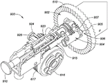
Fig. 9A-9F are internal perspective views depicting an exemplary embodiment of a proximal control device 200, the proximal control device 200 having a lock or locking mechanism 900 for preventing premature release of the implant 102. The locking mechanism 900 interfaces with a groove or channel 902 in a proximally facing surface of the face gear 610, as shown in fig. 9A-9B. The longitudinally, laterally and radially inwardly movable tracking mechanism 904 has a head portion with a protrusion 905 and is distally biased such that the protrusion 905 presses into the slot 902 and tracks within the slot 902. As the face gear 610 is rotated by the pinion gear 605 (not shown), the tracking mechanism 904 follows the helical groove 902 and moves radially inward. This movement continues until the implant 102 is almost fully deployed, but the proximal engagement member 115 is still held within the inner cavity 131 by the catch 136. At this point, the protrusion 905 enters a relatively deeper portion 906 (e.g., a cavity) of the slot 902, which portion 906 securely captures the tracking mechanism 904. Further rotation of the face gear 610 causes the tracking mechanism 904 to move laterally or rotate in a semi-circular arc to the position shown in fig. 9C-9D, wherein further lateral movement of the arm 907 of the tracking mechanism 904 is prevented by the fixed body 915. The face gear 610 is prevented from further rotation, which in turn prevents all gears from rotating and prevents the user from continuing to pull the trigger 202.
If the surgeon is satisfied with the placement of the implant 102, the unlocking actuator or tab 910 is pulled proximally, and the unlocking actuator or tab 910 is accessible to the user outside of the housing 203. The unlocking tab 910 is coupled, directly or indirectly, to the control line 146, which control line 146 is responsible for releasing the holder 142, as described with respect to fig. 2C and 2D. Thus, proximal movement of the unlocking tab 910 causes the holder 142 to move proximally and allow the distal engagement member 114 of the implant 102 to be released from the delivery device 103. The unlocking tab 910 may also be coupled with the tracking mechanism 904 such that proximal retraction of the tab 910 withdraws the protrusion 905 from within the slot 902. This action unlocks the device 200 and the user is free to continue to depress the trigger 202, which in turn feeds the spool 616 forward to further unwind the gripper shaft 138 and cause the proximal engagement member 115 and recess 139 of the implant 102 to exit the inner cavity 131 of the shaft 130. At this stage, both the distal and proximal engagement members 114, 115 of the implant 102 are exposed, and the implant 102 is free to disengage or release from the device 103.
The proximal control apparatus 200 may be configured to rotate the distal control member 140 relative to other components of the delivery apparatus 103 to facilitate removal of the distal engagement member 114 from the distal control apparatus 140. In the embodiment depicted in fig. 9E, second cam 940 is rotatable within main body 941. Distal control member 140 (not shown) is secured to cam 940 (e.g., with a set screw) such that rotation of cam 940 causes rotation of distal control member 140. The cam 940 has two inclined surfaces 944a and 944b, the inclined surfaces 944a and 944b being in contact with two rigid members (e.g., pins) 946a and 946b, respectively, the rigid members 946a and 946b being fixed to the main body 941 and located on opposite sides of the cam 940. Cam 940 is rotatable but longitudinally fixed relative to main body 941. Pulling the release tab 910 moves the body 941 and members 946a and 946b proximally. The cam 940 is not proximally movable, so contact of the member 946 on the ramped surface 944 causes the cam 940 to rotate, which in turn rotates the distal control member 140. Thus, retraction of the tab 910 releases the retainer 142 and rotates the distal control member 140, which distal control member 140 does not cover the distal engagement member 114 of the implant 102 (the implant 102 is now expanded into contact with the urethra). Rotation helps to withdraw distal engagement member 114 from recess 143 of member 140 and may ensure complete disengagement.
In some embodiments, distal control member 140 has a pre-set bend (not shown) proximal to retainer 142. When attached to the distal engagement member 114, the distal control member 140 deforms from this pre-set bent shape (e.g., as depicted in fig. 2B, 2G, and 2H) and is thus biased to return to this pre-set bent shape, which may also assist in disengagement of the member 140 from the implant 102 (instead of or in addition to embodiments in which the device 200 rotates the member 140).
A stop surface 912 is present on the tracking mechanism 904, the stop surface 912 opposing another stop surface 914 on the stationary body 915. In the position of the tracking mechanism 904 shown in fig. 9B, these opposing stop surfaces 912 and 914 prevent the unlocking tab 910 from proximally retracting because the main body 915 is a separate component that remains in a stationary position (e.g., by the housing 203). The lateral movement of the tracking mechanism 904 (e.g., in a semicircular arc) continues until the stop surface 912 ceases and exceeds the stop surface 914, as shown in fig. 9D. This feature prevents premature unlocking of the implant 102 by proximally retracting the unlocking tab 910 before the implant 102 is fully deployed.
The proximal control device 200 may also include an emergency release mechanism that allows the partially deployed implant 102 to be removed from the patient. The unlocking tab 910 may be uncoupled from the tracking mechanism 904 by disengaging the notch of the deflectable arm 920 from a detent 922 on the base of the tracking mechanism 904. In other embodiments, the notch and detent features may be reversed. An emergency release button 924 having a ramped surface 925 is positioned below the arm 920 (see fig. 9A-9B). Actuation of the release button 924 (e.g., by pushing) causes the ramp surfaces 925 to deflect the arms 920 upward and decouple the notch from the pawl 922, as depicted in fig. 9E. In this state, the unlocking tab 910 is decoupled from the tracking mechanism 904 and is free to retract proximally even when the stop surfaces 912 and 914 are in the relative positions. Proximal retraction of the unlocking tab 910 retracts the control wire 146 and releases the distal engagement member 114 of the implant 102 from the distal control member 140. At this point, the partially deployed implant 102 remains attached to the grip 136, and the grip 136 may be retracted proximally into the outer shaft 120 and then removed completely from the patient.
An example embodiment of a delivery method.
Fig. 10A is a flow chart depicting an example embodiment of a method 1000 of delivering an implant 102 using the system 100. The distal end region of the outer shaft 120 is inserted into the urethra, preferably with the inner shaft 130, the distal control member 140, and the anchor delivery component 150 in a retracted state and fully contained within the outer shaft 120 such that no portion extends from the open distal terminal end of the outer shaft 120. After advancement into the urethra, at step 1002, the anchor delivery member 150 is advanced distally relative to the remainder of the delivery device 103 (e.g., members 120, 130, and 140) and used to deploy the anchors 152 within the bladder. In some embodiments, deployment of the anchors 152 can be an inflation of one or more balloons (e.g., as depicted in fig. 2B and 4H-4J) introduced by passing an inflation medium through an injection port (e.g., a luer taper). Fig. 6A depicts a conduit 650 for balloon inflation. In other embodiments, deployment of the anchor 152 can be advancement of one or more wire form members from the anchor delivery member 150 such that they deflect into a position opposite the bladder wall (e.g., fig. 4A-4G). Longitudinal positioning (e.g., advancement and retraction) of the anchor delivery member 150 and/or any wire form member can be accomplished manually by a user manipulating the proximal end of the anchor delivery member 150 and/or any wire form member (directly or with the proximal control device 200).
At step 1004, the anchor 152 may be held in tension against the bladder wall by applying a proximally directed force on the device 200. Thus, the anchors 152 can provide an ordinate to the system 100 from which the implant 102 can be deployed in a precise location. This feature may ensure that the implant is not placed too close to the bladder neck.
At 1006, distal control member 140 and inner shaft 130 can then be advanced distally from within outer shaft 120 if they have not been advanced distally (e.g., step 1006 can occur before steps 1002 and/or 1004). The user may manipulate the position of the proximal control device 200 by means of imaging (as described herein) until the implant 102 is in the desired position. Once the implant 102 is in the desired position, the implant deployment process may begin. The steps for implant deployment may be performed automatically by user actuation of the proximal control device 200 (e.g., actuation of the trigger 202, selection of a position for the switch 604, etc.), or these steps may be performed directly by manual manipulation of each component of the delivery device 103, or by a combination of both, as desired for a particular embodiment.
In some embodiments, deployment of implant 102 from within cavity 131 is accomplished entirely by (1) advancing grip 136 distally relative to inner shaft 130 without moving inner shaft 130, while in other embodiments, deployment of implant 102 from within inner cavity 131 is accomplished entirely by (2) retracting inner shaft 130 proximally relative to grip 136 without moving grip 136. In some embodiments, the deployment of the implant 102 is accomplished entirely by (3) a combination of the two movements. In still other embodiments, deployment of the implant 102 is accomplished entirely by a combination of (1), (2), or (3) one or more rotations of the inner shaft 130 relative to the distal control member 140 in one or more directions (e.g., clockwise or counterclockwise).
An example embodiment of a sequence of steps 1008, 1010, and 1012 for deploying the implant 102 is described with reference to the timing diagrams of fig. 10A and 10B. Referring first to fig. 10A, at step 1008, the first annular structure 111a is caused to exit the cavity 131 of the inner shaft 130, at step 1010, the interconnect 112 is caused to exit the cavity 131, and at step 1012, the second annular structure 111b is caused to exit the cavity 131. Steps 1010 and 1012 may be repeated for each additional interconnect 112 and loop structure 111 present on the implant 102.
In FIG. 10B, step 1008 begins at T0 at the leftmost side of the timing diagram. The deployment of the loop structure 111a corresponds to the duration labeled 1008, the deployment of the interconnect 123 corresponds to the time span 1010, and the deployment of the loop structure 111b corresponds to the time span 1012. One of ordinary skill in the art will appreciate that the distinction between the deployment of the ring structure 111 and the deployment of the interconnect 112 is approximate, as the transition between those portions of the implant 102 may be gradual and need not have precise limits.
The embodiment described with respect to fig. 10B is for an implant having a loop structure 111, the loop structure 111 having opposite winding directions (e.g., clockwise, then counterclockwise, then clockwise, etc.). Three different motions are indicated in fig. 10B. At the top is rotational movement of the inner shaft 130 in one direction (e.g., clockwise), in the middle is longitudinal movement (e.g., proximal or distal) of one or more components of the delivery device 103, and at the bottom is rotational movement of the inner shaft 130 in the opposite direction (e.g., counterclockwise) indicated at the top. In embodiments where the annular structures 111 of the implant 102 are all wound in the same one direction, the rotation of the inner shaft 130 will also be in only one direction.
From time T0 to T1, deployment of the implant 102 is completed by rotating the inner shaft 130, as indicated in region 1031. Meanwhile, in region 1032, the grip 136, and thus the implant 102, is advanced distally without moving the outer shaft 120 longitudinally (neither distally nor proximally) or rotationally, and without also moving the inner shaft 130 longitudinally (neither distally nor proximally). By way of example, within the proximal control device 200, rotational movement of the inner shaft 130 is accomplished without corresponding longitudinal movement of both the inner shaft 130 and the outer shaft 120 by translating user depression of the trigger 202 (via the yoke and pawl) into rotation of the pinion 605 and face gear 610. Rotation of the face gear 610 also rotates the cam 703 of the cam assembly 702 (fig. 7A-7B) while the guide member 706 is in the radial slot portion (e.g., 7191 a) and thus any of the shafts 120 and 130 do not move longitudinally. Rotation of the cam 703 also causes the second gear assembly 800 (fig. 8) to rotate the inner shaft 130. Advancement of the gripper 136 is caused by the face gear 610 rotating the input gear 612, which input gear 612 in turn rotates the spool gear 614 (fig. 6A-6B), and causes the spool 616 to rotate and distally unwind the gripper shaft 138.
From time T1 to T2, rotation of the inner shaft 130 stops, but distal advancement of the catch 136 continues, while the shafts 120 and 130 do not move longitudinally. By way of example, within the proximal control device 200, the user continues to depress the trigger 202 and the cam 703, along with the guide member 706, continues to rotate within the radial slot portion (e.g., 719 a). Rotation of the cam 703 continues to rotate the ring gear 802 of the second gear assembly 800, but at this point an interruption (no teeth) in the ring gear 802 is reached, any of the planet gears 810, 812, and 814 do not rotate, and thus rotation of the sun gear 816 and the inner shaft 130 stops. In this embodiment, the deployment of the first loop structure 111a is completed at time T2.
From time T2 to T4, the unfolding of first interconnect 112 occurs. In region 1033, from time T2 to T4, no distal advancement of the grip 136 (and implant 102) occurs. Deployment of the interconnecting portion 112 is completed by proximal retraction of both the outer shaft 120 and the inner shaft 130, while the catch 136 remains in place. This causes the interconnecting portion 112 to move away from the inner cavity 131 of the shaft 130. By way of example, in the proximal control device 200, the user continues to depress the trigger 202 and the face gear 610 continues to rotate, as do both the cam 703 and the input gear 612. A discontinuity 623 is reached in the input gear 612 and rotation of the input gear 612 no longer causes rotation of the spool gear 614 and thus distal advancement of the gripper shaft 138 is stopped. Within the cam assembly 702, the guide member 706 transitions from a radial slot portion (e.g., 719 a) to a sloped slot portion (e.g., 717 a), and rotation of the cam 703 causes the guide member 706 to move proximally. With the guide member 706 coupled with the shafts 120 and 130, these shafts 120 and 130 also move proximally.
With respect to the rotation of the inner shaft 130, from time T2 to T3, no rotation of the inner shaft 130 occurs. Within the proximal control device 200, the interrupted portion of the ring gear 802 continues and there is no rotation of the shaft 130 caused by the sun gear 816.
In embodiments where the interconnecting portion 112 is straight, it may be desirable to inhibit rotation of the shaft 130 from time T2 to T4 while the interconnecting portion 112 is unwound. For embodiments in which the interconnecting portion 112 is curved, such as the embodiments of figures 1B-1D, it may be desirable to initiate rotation of the inner shaft 130 during deployment of the interconnecting portion. Figure 10B depicts deployment for the curved interconnection 112 and, from T3-T4, the inner shaft 130 is rotated in the opposite direction indicated by region 1034. By way of example, within the proximal control device 200, the user continues to depress the trigger 202 and this motion is translated to a ring gear 802, the ring gear 802 having a region where the teeth engage with a planetary gear that is responsible for movement of the sun gear 816 in the opposite direction. Rotation of the sun gear 816 in the opposite direction is thus initiated, and the inner shaft 130 similarly rotates in the opposite direction from that time T0 to T1, which facilitates deployment of the interconnection 112 and initiates rotation of the inner shaft in a direction suitable for winding the second annular structure 111b in the opposite direction.
At T4, the deployment of interconnect 112 is complete and the deployment of second loop structure 111b begins. Proximal retraction of shafts 120 and 130 stops, as indicated by the discontinuation of region 1033. Distal advancement of the grip shaft 138 resumes in region 1035 at T4, while outer shaft 120 moves neither rotationally nor longitudinally. As indicated in region 1034, rotation of the inner shaft 130 continues, but the inner shaft 130 does not move longitudinally. By way of example, within the proximal control device 200, the user continues to depress the trigger 202. Rotation of the cam 703 continues, but the guide member 706 reaches the second radial slot portion (e.g., 719 b), and proximal movement of the guide member 706 stops (retraction of the shafts 120 and 130 also stops). Rotation of sun gear 816 continues. The interrupted portion 623 of the input gear 612 is halted and the teeth 620 reengage the spool gear 614, causing both the spool gear 614 and the spool 616 to begin rotating again and thus distal advancement of the gripper shaft 138 to begin as well.
These movements continue until time T5, at which time rotation of the inner shaft 130 stops. Within the proximal control device 200, the interrupted portion of the ring gear 802 is reached and the gear 802 is disengaged from the planetary gears and rotation of the sun gear 816 is stopped. From time T5-T6, the user continues to depress the trigger 202 and the components operate in a similar motion as described from time T1 to T2. If another interconnect 112 and ring structure 111 are present, the sequence starting at time T6 may be the same as the described sequence starting at time T2 and continuing to time T6. This process may be repeated as desired until all of the loop structures 111 of the implant 102 are deployed. In some embodiments, further depression of trigger 202 may be stopped by locking mechanism 900 (fig. 9A-9B) to prevent premature deployment and release of proximal engagement portion 115.
In many of the embodiments described herein, deployment of all of the loop structures 111 may occur with a single continuous depression of the trigger 202. In all of these embodiments, the proximal control device 200 can be configured instead such that repeated pulling of the trigger 202 is required to deploy all of the loop structures 111 of the implant 102.
During deployment, for example, after time T0 until deployment of the proximal-most loop structure 112 is complete, if the surgeon wishes to recapture the implant 102, depression of the trigger 202 may be stopped. The trigger 202 may be spring loaded or otherwise biased to return to an outermost position. The physician can adjust the transducer 604 from a position corresponding to deployment to a different position corresponding to recapture. This adjustment of the transducer 604 will disengage from the pawl 603 and engage the pawl 602. The clinician can depress the trigger 202 again and this depression will translate into a reverse motion of the face gear 610, which in turn translates into a reverse motion of the remainder of the first gear assembly 600, cam 703, and second gear assembly 800. For example, if the converter 604 is adjusted at any time between times T0 and T6, the next depression of the trigger 202 will cause the sequence of events to reverse from right to left in FIG. 10B. Since these movements are merely the inverses of the movements already described, they will not be described in detail here.
If the surgeon is satisfied with the deployment procedure, at 1014, the distal engagement portion 114 and proximal engagement portion 115 of the implant 102 can be released from the distal control member 140 and grip 136, respectively. By way of example, in the proximal control device 200, the surgeon may pull on the tab 910 to allow the remaining stroke of depressing the trigger 202, which in turn may deploy the proximal engagement portion 115 of the implant 102 by distal advancement of the grip 136, proximal retraction of the shafts 120 and 130, or both. The tab 910 may be coupled with the control wire 146, and pulling the tab 910 may pull the wire 146 and remove the holder 142 from the distal engagement portion 114.
The anchors 152 can then be recaptured (e.g., balloon deflation or wire form member retraction) and the anchors 152 withdrawn into the anchor delivery member 150 (if desired). The anchor delivery member 150, distal control member 140, and inner shaft 130 can be retracted into the outer shaft 120 and then withdrawn from the urethra.
Example embodiments of a user assembly of a proximal control device.
Referring again to fig. 5A, the proximal control device 200 can include a movable (e.g., retractable and/or advanceable) handle portion 1102, which handle portion 1102 can be moved relative to a more proximally located handle portion 1103. Fig. 5A depicts the movable handle portion 1102 in a distally advanced position prior to deployment of the implant 102, and fig. 5B depicts the portion 1102 in a proximally retracted position after deployment of the implant 102. The movable portion 1102 is securable to the outer shaft 120 and moves with the outer shaft 120 and is also movable independently of the inner shaft 130, distal control member 140, and anchor delivery member 150 (not shown).
Fig. 11A is an internal view of an example embodiment of the movable portion 1102 of the proximal control device 200, taken from an inverted view compared to fig. 5A-5B. The proximal end region 105 of the delivery device 103 is shown at the right side coupled with the housing 1103 of the movable portion 1102, and at the left side the faceted shaft 708 is shown. The shaft 708 may be faceted to allow for an interference fit with the hub 707, although other configurations and fastening techniques may be used such that the shaft 708 is cylindrical (e.g., fastened to the hub 707 with an adhesive). The coupling mechanism 1106 is mounted or formed within the housing 1103 and will be described in more detail with respect to fig. 11B-11E. Also included within the housing 1103 is imaging hardware 1202, which imaging hardware 1202 will be described in more detail with respect to fig. 12A-12E.
Fig. 11B is an interior view of the coupling mechanism 1106 depicted from a closer perspective than fig. 11A. Here, the coupling mechanism 1106 includes a user actuator 1107 that is configured in this embodiment as a latch slidable within a track 1108 provided by the housing 1109. Fig. 11C depicts the coupling mechanism 1106 with the proximal side of the housing 1109 removed to allow the internal components to be seen. Fig. 11D depicts the coupling mechanism 1106 of fig. 11C with the latch 1107 removed as well, and fig. 11E depicts the coupling mechanism 1106 of fig. 11D with the housing 1109 removed for further simplicity of description.
The latch 1107 is coupled with a resiliently deflectable member 1110 disposed within the housing 1109. Movement of latch 1107 from a leftmost position to a rightmost position (as depicted herein) causes member 1110 to bend against inclined surface 1119. The member 1110 is biased toward the straight configuration (as shown in fig. 11C-11D), and releasing the latch 1107 in the rightmost position allows the latch 1107 to return to the leftmost position by the resilient action of the member 1110. The member 1110 can be configured as desired according to application needs. For example, in this embodiment, the member 1110 is a nitinol wire.
When in the leftmost position, the member 1110 can be received within one or more slots in the rotary adapter 1112. In the embodiment of fig. 11E, there are two slots 1114 and 1115, each of which can receive the member 1110, such that as the rotary adapter 1112 rotates, the member 1110 can slide in the slots 1114 and 1115, but any longitudinal movement (advancement and/or retraction) of the rotary adapter 1112 will result in similar movement of the member 1110.
Prior to use in an implantation procedure, the proximal end of the inner shaft 130 is coupled with a rotation adapter 1112, which rotation adapter 1112 is in turn coupled with a faceted shaft 708, which faceted shaft 708 is in turn coupled with the proximal portion 1103 of the proximal control device 200. The outer shaft 120 is coupled with the movable portion 1102, but the portions 1103 and 1102 are separate and not coupled together. A medical professional or other user can advance the distal end of the inner shaft 130 into the movable portion 1102 of the proximal control device 200 until the slots 1114 and/or 1115 of the rotation adapter 1112 engage the deflectable member 1110. Insertion of the inner shaft 130 through the portion 1102 may be accomplished by means of one or more ramps 1120 depicted in figure 11B. The distal end 1118 of the rotation adapter 1112 can be tapered or necked down in one or more regions to assist in this insertion by deflecting the member 1110 until the first slot 1115 is located in close proximity to the member 1110 at which time the member 1110 will snap into the slot. When wire 1110 is engaged with one of slots 1114 or 1115, movable portion 1102 couples with proximal portion 1103 of proximal control device 200. In certain embodiments, at this point, the proximal control device 200 is assembled and ready for use in an implantation procedure.
Example embodiments of imaging devices and uses.
In certain example embodiments, the coupling of the movable portion 1102 (which is secured to the outer shaft 120) to the rotary adapter 1112 (which in turn is secured to the multi-faceted shaft 708, the guide member 706, and the inner shaft 130) causes the outer shaft 120 to track the movement of the inner shaft 130. As described with respect to fig. 2A, the imaging device and the illumination device (see fig. 12D-12E) can be placed in one or more cavities 122 and 124 at the distal end of the outer shaft 120. These devices may be mounted at the distal terminal end of their respective lumens (or a common lumen) at locations spaced a small distance proximally of the distal terminal end of the inner shaft 130 (from which the implant 102 exits during delivery). As the inner shaft 130 moves proximally in the longitudinal direction, the outer shaft 120 also moves proximally in the longitudinal direction, wherein the same spacing is maintained between their opposing distal terminal ends. Conversely, as the inner shaft 130 moves distally, the outer shaft 120 also moves distally, wherein the same spacing (i.e., at the same rate) is maintained. Thus, the system 100 allows for delivery of the implant 102 from the inner shaft 130 to image at a constant interval from the distal terminal end of the inner shaft 130. Because the slots 1114 and 1115 are annular (e.g., extend like a ring around the circumference of the rotation adapter 1112), the inner shaft 130 is allowed to rotate without causing similar rotation in the outer shaft 120. The deflectable member 1110 simply slides along the respective slot 1114 or 1115.
If a user or medical professional desires to place the imaging device at different intervals spaced from the distal terminal end of the inner shaft 130, a coupling mechanism 1106 can be used to release the coupling between the movable portions 1102 and 1103 and the movable portion 1102 can be moved such that different slots engage with the deflectable member 1110. For example, disengaging from slots 1115 and engaging with slots 1114 will increase the separation between the imaging device at the distal terminal end of outer shaft 120 and the distal terminal end of inner shaft 130, thus allowing a user to image with a relatively wider field of view. This feature provides the user with the ability to adjust the field of view. The coupling mechanism 1106 may be coupled in a first position corresponding to a first one of the slots 1114 and 1115, and if the imaging field of view is poor, the user may decouple the mechanism 1106 and switch to a second position corresponding to the other one of the slots 1114 and 1115. Although only two slots 1114 and 1115 are present in the embodiments described herein, any number of one, two, three, four, or more slots may be used, each independently selectable from the others, and each corresponding to a different position and field of view. The ability of the imaging and illumination device to automatically move in synchronization with the longitudinal movement of the inner shaft 130 during deployment may be used with any of the embodiments described herein.
Fig. 12A depicts a housing 1203 for imaging hardware 1202. Fig. 12B depicts components on the interior of housing 1203, and fig. 12C depicts these components from a closer perspective. Fig. 12D is a perspective view depicting a proximal side of the distal end region of outer tubular member 120, and fig. 12E is a perspective view depicting a distal side of the distal end region of outer tubular member 120. The first bus 1204, which in this embodiment is in the form of a ribbon cable, is connected at its distal end (fig. 12D) to an imaging device 1220 in a distal end region end 1224 of the outer tubular member 120 (not shown). The first bus 1204 may be routed through a cavity (e.g., one of the cavities 122 and 124) of the outer tubular member 120 and have its proximal end connected to one or more contacts (fig. 12C), in this example four contacts 1205 and 1208, for power, ground, receive signals, and clock.
A second bus 1210 (which in this embodiment is also in the form of a ribbon cable) is connected at its distal end (fig. 12D) to a lighting device 1222 in a distal end area tip 1224. The second bus 1210 can be routed through the same or different cavity (e.g., one of the cavities 122 and 124) of the outer tubular member 120 and has its proximal end connected to one or more contacts (fig. 12C), in this example two contacts 1211 and 1212, for power and ground. These contacts are located on a printed circuit board 1216, which printed circuit board 1216 may have additional imaging hardware (not shown) coupled thereto, including passive RLC components and active components (e.g., transistors, diodes, and/or semiconductor chips). The output circuitry that transmits the received image may be wired circuitry that outputs the image to a display via a cable, or may be wireless circuitry that wirelessly transmits the image to a local receiver having a display. The flush port cavity 1223 is also shown in fig. 12D-12E. The order of the positions of the imaging device 1220, the illumination device 1222, and the irrigation port cavity 1223 can be rearranged from the positions described and illustrated herein.
Example embodiment of implant placement.
All embodiments of the system 100 described herein may be used to deliver the implant 102 to various locations near the prostate or other locations within the human anatomy. Figure 13 is a cross-sectional view of a male anatomy providing context for use in describing various examples of implant locations within the prostatic urethra. Here, the prostate 1302 is centrally located, while the bladder wall 1304 and bladder 1305 are located above. The prostatic urethra 1306 extends from the bladder 1305, down through the ejaculatory duct 1307, and through the prostate 1302. The prostatic urethra 1306 becomes the urethral meatus 1308 at the general location of the external urethral sphincter 1309 and continues to exit the body. The rectum is indicated at 1310.
Fig. 14A is a section rotated from the viewpoint of fig. 13 such that the rear direction extends into the page and the front direction extends out of the page. Here, an example embodiment of the implant 102 is shown positioned within the prostatic urethra 1306. From this perspective, the implant 102 is generally centrally positioned within the prostatic urethra 1306, in other words, the distances spaced from the upper and lower edges of the prostate 1302 are generally equal. The placement of the implant 102 is generally determined by the medical professional and may be offset or inferior from the position shown here, but is generally preferred to be within the prostatic urethra 1306.
Fig. 14B depicts a region of the prostate 1302 from generally the same perspective as fig. 13, but with more detail. Here, the prostate 1302 is in an enlarged state with the central lobe 1402 protruding into the prostatic urethra 1306. Figure 14C is a cross-section taken along line 14C-14C of figure 14B and illustrates the slit-like nature of the prostatic urethra 1306 in the enlarged prostate 1302 herein, wherein the width of the urethra 1306 widens as it travels from anterior to posterior.
Fig. 14D depicts an example embodiment of the posteriorly placed implant 102 within an example anatomy described with respect to fig. 14B, and fig. 14E is a cross-section taken along line 14E-14E of fig. 14D. As can be seen here, the implant 102 is placed generally along the posterior-most surface of the prostatic urethra 1306. The implant 102 is sized to have a maximum diameter at its maximum central width that is less than the width of the prostatic urethra 1306 (e.g., less than 50% of the width, less than 65% of the width, less than 80% of the width, etc.) such that the implant 102 can be described as being positioned substantially on the posterior side of the prostatic urethra 1306 and not in contact with the anterior-most side of the urethra 1306. A schematic of this placement is shown in fig. 14E, where the opening through the prostate 1302 created by the implant 102 is positioned primarily on the posterior side of the prostate 1302 and urethra 1306.
Fig. 14F depicts an example embodiment of the anteriorly placed implant 102 within the example anatomy described with respect to fig. 14B, and fig. 14G is a cross-section taken along line 14G-14G of fig. 14E. As can be seen here, the implant 102 is generally placed along the anterior-most surface of the prostatic urethra 1306. The implant 102 can be sized to have a maximum diameter at its maximum central width that is less than the width of the prostatic urethra 1306 (e.g., less than 50% of the width, less than 65% of the width, less than 80% of the width, etc.) such that the implant 102 can be described as being positioned substantially on the anterior side of the prostatic urethra 1306 and not in contact with the posterior-most side of the urethra 1306. A schematic of this placement is shown in fig. 14G, where the opening through the prostate 1302 created by the implant 102 is positioned primarily on the anterior side of the prostate 1302 and urethra 1306. With both posterior and anterior placement, the implant 102 may still be placed generally centrally with respect to the prostate 1302, as shown in fig. 14A. The deployment of the implant 102 in the posterior or anterior position is generally determined by the medical professional. Other variations of placement may also be used, including placement centrally between the posterior-most and the medial-most sides of the urethra 1306, and variations in size may be used such that the implant 102 has a relatively larger or smaller diameter relative to the prostate 1302 than shown here.
The embodiments described herein are re-set forth and expanded in the following paragraphs without explicit reference to the figures. In many example embodiments, a system for delivering an implantable device is provided, wherein the system comprises a delivery device comprising: an outer tubular member; an inner tubular member having a first inner lumen and a second inner lumen, the inner tubular member being slidable within the outer tubular member, wherein the first inner lumen is adapted to receive an elongate gripper member configured to releasably couple with a proximal portion of an implant; and a distal control member slidable within the second inner lumen, wherein the distal control member includes a retainer configured to releasably couple with the distal portion of the implant.
In some embodiments, the implant is configured to maintain the prostatic urethra in an at least partially open state. In some embodiments, the implant has a body including first and second annular structures and an interconnect extending between the first and second annular structures. The body of the implant may be only a single wire. The implant may include a distal engagement member configured to releasably engage with the holder and/or a proximal engagement member configured to releasably engage with the elongated grip member. In some embodiments, the implant includes a wire-like distal engagement member and/or a wire-like proximal engagement member that extends proximally away from a distal-most portion of the implant. In some embodiments, the first loop structure may be a distal-most loop structure of the implant and have a relatively smaller width than the second loop structure.
In some embodiments, the inner tubular member is slidable and rotatable relative to the distal control member while the holder is releasably coupled with the distal portion of the implant. The system may further include an elongate member coupled with the holder, the elongate member having a proximal end that is manipulable by a user to allow release of the distal portion of the implant from the holder. In some embodiments, the holder is tubular and adapted to slide along the distal control member. The distal control member may include a recess adapted to receive a distal portion of the implant, and the holder may be movable to uncover the recess while the distal portion of the implant is received within the recess. In some embodiments, the retainer includes a slit through which the implant can pass.
In some embodiments, the system includes an elongate anchor member. The elongate anchor member may comprise an anchor configured to contact the bladder wall. The anchor may be an inflatable balloon or a plurality of inflatable balloons. In some embodiments, the elongate anchor member comprises a wire form member having a portion configured to automatically deflect when deployed.
In some embodiments, the elongate gripper member comprises a recess configured to releasably couple with a proximal portion of the implant. In some embodiments, the system is configured such that the proximal portion of the implant is free to release from the recess of the elongate gripper member when the recess is not bounded by the first inner cavity.
In some embodiments, a proximal control device is included and is coupled to the proximal end region of the delivery device. The proximal control device may be manipulable by a user to control deployment of the implant from the delivery device. In some embodiments, the proximal control apparatus includes a housing and is configured to advance the elongate gripper member distally relative to the housing and the inner tubular member, and/or is configured to retract and rotate the inner tubular member proximally relative to the housing and the distal control member, and/or is configured to retract the outer tubular member proximally relative to the housing.
In some embodiments, the proximal control device comprises: a user actuator; a first gear assembly coupled with the user actuator; a cam assembly coupled with the first gear assembly; and a second gear assembly coupled with the cam assembly. In some embodiments, the first gear assembly is configured to control longitudinal movement of the elongated gripper member, the cam assembly is configured to control longitudinal movement of the inner tubular member, and/or the second gear assembly is configured to control rotation of the inner tubular member.
In many embodiments, a system for delivering an implantable device is provided, wherein the system comprises: a delivery device comprising a first elongate member having an inner cavity, an elongate gripper member slidable within the inner cavity and configured to hold a proximal portion of the implant, and a distal control member configured to hold a distal portion of the implant; and a proximal control device coupled with the proximal end region of the delivery device, the proximal control device including a user actuator and a housing.
In some embodiments, the proximal control device includes a first gear assembly within the housing, the proximal control device configured to translate movement of the user actuator into movement in the first gear assembly. In some embodiments, the proximal control device includes a switch that selects between movement of the first gear assembly in the first direction and movement of the first gear assembly in the second direction. In some embodiments, the user actuator is coupled to a yoke that is coupled to the first jaw and the second jaw. The shifter may selectively engage either the first pawl or the second pawl with the pinion gear. The proximal control device may be configured such that rotation of the pinion gear results in rotation of the face gear. The proximal control device may be configured such that rotation of the face gear results in rotation of a spool coupled with the elongate gripper member.
In some embodiments, the system further includes an input gear engaged with the face gear and a spool gear engaged with the input gear, the spool gear coupled with or integrated with the spool. In some embodiments, the input gear is an interrupted gear, and rotation of the spool gear by the input gear causes rotation of the spool and longitudinal movement of the elongate gripper member. In some embodiments, movement of the first gear assembly in a first direction causes distal movement of the elongated grip member, and movement of the first gear assembly in a second direction causes proximal movement of the elongated grip member.
In some embodiments, the proximal control includes a cam assembly within the housing, the proximal control configured to translate movement of the user actuator into movement in the cam assembly. The cam assembly may be coupled with the first elongate member and may be configured to move the first elongate member proximally relative to the housing. In some embodiments, the cam assembly includes a rotatable cam having a slot, the first elongate member being coupled with a guide member received within the slot. In some embodiments, the slit includes an inclined slit portion and a radial slit portion. The cam assembly may include an inner tube having a longitudinal slot, wherein the guide member is received in the longitudinal slot.
In some embodiments, the first gear assembly includes a face gear having a first set of teeth that engage teeth of another gear in the first gear assembly, wherein the face gear is coupled with the cam assembly such that movement of the face gear results in movement in the cam assembly.
In some embodiments, the proximal control device includes a second gear assembly, and movement in the cam assembly can result in movement in the second gear assembly. The second gear assembly may be coupled with the first elongate member and may be configured to rotate the first elongate member relative to the housing. The second gear assembly may include a sun gear having a bore configured to receive the first elongate member such that rotation of the sun gear causes rotation of the first elongate member. In some embodiments, the second gear assembly includes a ring gear coupled with the cam assembly and with the sun gear with a planetary gear assembly. The ring gear may be engaged with the planetary gear assembly such that rotation of the ring gear in a first direction causes rotation of the sun gear in a first direction and rotation of the ring gear in a second direction causes rotation of the sun gear in a second direction, the rotation of the sun gear in the first direction being opposite the rotation of the sun gear in the second direction.
In some embodiments, the proximal control includes a releasable locking mechanism that prevents a proximal portion of the implant held by the elongate gripper member from exiting the inner cavity. In some embodiments, the locking mechanism includes a movable tracking mechanism that interfaces with a slot in the face gear of the first gear assembly, the proximal control device being configured such that movement of the face gear moves the tracking mechanism as the implant exits the internal cavity. The proximal control may be configured such that the tracking mechanism is prevented from further movement until the proximal portion of the implant exits the inner cavity.
In some embodiments, the proximal control includes a release structure configured to be actuated by a user, wherein the release structure is configured to disengage the tracking mechanism from the face gear to allow the proximal portion of the implant to exit the inner lumen. The release structure may be a pull tab and may be coupled with the elongated gripper member.
In many embodiments, there is provided a method of delivering an implant, the method comprising: advancing a delivery device within a body lumen of a patient, wherein the delivery device comprises a first tubular member containing an implant, a distal control member slidable within the first tubular member and releasably coupled with a distal portion of the implant, and an elongate gripper member slidable within the first tubular member and releasably coupled with a proximal portion of the implant; causing relative movement between the elongate gripper member and the first tubular member to expose at least a portion of the implant from within the first tubular member; and releasing a distal portion of the implant from the distal control member and a proximal portion of the implant from the elongate grip member.
In some embodiments, the body cavity is the prostatic urethra of a human. In some embodiments, upon release of the distal portion and the proximal portion, the implant is released from the delivery device in a state adapted to maintain the prostatic urethra in an at least partially open state.
In some embodiments, the implant has a body including first and second annular structures and an interconnection extending between the first and second annular structures, and causing relative movement may include advancing the elongate gripper member distally. In some embodiments, the method further comprises rotating the first tubular member in a first direction relative to the distal control member during exposure of the first annular structure from the first tubular member. In some embodiments, the method further comprises rotating the first tubular member relative to the distal control member in a second direction during exposure of the second annular structure from the first tubular member, the second direction being opposite the first direction. Rotation of the first tubular member in the first direction and the second direction may occur when the distal control member is releasably coupled with the distal portion of the implant.
In some embodiments, the method further comprises proximally retracting the first tubular member relative to the elongate gripper member and the distal control member to expose the interconnect from the first tubular member. In some embodiments, the method further comprises rotating the first tubular member while proximally retracting the first tubular member. In these embodiments, the interconnects may be curved.
In some embodiments, the holder couples the distal portion of the implant to the distal control member, and the method includes releasing the holder to release the distal portion of the implant from the distal control member.
In some embodiments, the method further comprises exposing a proximal portion of the implant from within the first tubular member to release the proximal portion of the implant from the elongate grip member.
In some embodiments, the method further comprises anchoring the delivery device against the bladder wall prior to causing relative movement between the elongate grip member and the first tubular member. In some embodiments, anchoring the delivery device includes inflating a balloon in the bladder.
In some embodiments, the proximal control device is coupled with the proximal end region of the delivery device, and the method includes moving a user actuator of the proximal control device by a user, wherein moving the user actuator causes movement in a first gear assembly of the proximal control device. In some embodiments, the first gear assembly causes the elongate gripper member to advance distally relative to the first tubular member. In some embodiments, the first gear assembly causes movement in the cam assembly and the second gear assembly. In some embodiments, movement in the cam assembly causes intermittent retraction of the first tubular member relative to the distal control member. In some embodiments, movement in the second gear assembly causes intermittent rotation of the first tubular member relative to the distal control member.
In some embodiments, the user actuator is a first user actuator and the method includes actuating a second user actuator of the proximal control device. In some embodiments, actuating the second user actuator unlocks the locking mechanism and allows a distal portion of the implant to be released from the distal control member and a proximal portion of the implant to be released from the elongate gripper member. In some embodiments, actuating the second user actuator removes the holder from the distal portion of the implant and rotates the distal control member to disengage the distal portion of the implant from the distal control member.
In some embodiments, the first tubular member is an inner tubular member slidably received within an outer tubular member of the delivery device.
In many embodiments, a system for delivering an implant is provided, wherein the system comprises a delivery device comprising: an outer tubular member including an imaging device located in a distal end region of the outer tubular member; an inner tubular member within the outer tubular member, wherein the inner tubular member is adapted to receive at least a portion of an implant; one or more structures slidably advanceable within the inner tubular member to cause deployment of the implant from within the inner tubular member; and a proximal control device coupled with the inner tubular member and the one or more structures and releasably coupled with the outer tubular member with a coupling mechanism, wherein the proximal control device is configured to simultaneously longitudinally move the inner and outer tubular members.
In some embodiments, the system further comprises an implant. The implant may be configured to maintain the prostatic urethra in an at least partially open state. In some embodiments, the implant has a body including first and second annular structures and an interconnect extending between the first and second annular structures.
In some embodiments, the one or more structures comprise: an elongate gripper member configured to releasably couple with a proximal portion of an implant; and a distal control member configured to releasably couple with a distal portion of the implant. In some embodiments, the distal control member comprises a holder configured to releasably couple with a distal portion of the implant, wherein the implant comprises a distal engagement member configured to releasably couple with the holder. In some embodiments, the implant includes a proximal engagement member configured to releasably couple with the elongate gripper member. In some embodiments, the implant includes a wire-like distal engagement member extending proximally away from a distal-most portion of the implant. In some embodiments, the implant includes a wire-like proximal engagement member.
In some embodiments, the proximal control device is configured to rotate and longitudinally move the inner tubular member relative to the distal control member while the distal control member is releasably coupled with the distal portion of the implant. In some embodiments, the proximal control device is configured to rotate the inner tubular member without rotating the outer tubular member.
In some embodiments, the system further comprises an elongate member coupled with the holder and having a proximal end that is manipulable by a user to allow release of the distal portion of the implant from the holder. In some embodiments, the holder is tubular and adapted to slide along the distal control member. In some embodiments, the distal control member includes a recess adapted to receive a distal portion of the implant. In some embodiments, the retainer is movable to uncover the recess while the distal portion of the implant is received within the recess. In some embodiments, the retainer comprises a slit.
In some embodiments, the system further comprises an elongate anchor member. In some embodiments, the elongate anchor member comprises an anchor configured to contact the bladder wall. In some embodiments, the anchor is an inflatable balloon. In some embodiments, the elongate anchor member comprises a plurality of balloons. In some embodiments, the elongate anchor member comprises a wire form member having a portion configured to automatically deflect when deployed.
In some embodiments, the elongate gripper member comprises a recess configured to releasably couple with a proximal portion of the implant. In some embodiments, the system is configured such that the proximal portion of the implant is free to release from the recess of the elongate gripper member when the recess is not bounded by the first inner cavity.
In some embodiments, the proximal control device comprises a first portion comprising a first housing comprising the handle and a second portion comprising a second housing, the second portion being slidable relative to the first portion. In some embodiments, the inner tubular member is secured to the first housing and the outer tubular member is secured to the second housing. In some embodiments, release of the coupling mechanism allows the first portion to be uncoupled from the second portion. In some embodiments, the coupling mechanism includes a deflectable member that is receivable within a slot of a shaft portion of the first portion of the proximal control device.
In some embodiments, the groove is annular. And extends around a periphery of the shaft portion, wherein the shaft portion is secured to the inner tubular member. In some embodiments, the shaft portion includes a plurality of slots, each adapted to receive a deflectable member. In some embodiments, the deflectable member is slidable within the slot such that the shaft portion is rotatable while the deflectable member is received within the slot.
In some embodiments, the second portion includes a flexible bus having a first end electrically connected to the printed circuit board within the second portion and a second end electrically connected to the imaging device.
In some embodiments, the distal end region of the outer tubular member further comprises an illumination device.
In some embodiments, the second portion comprises: a first flexible bus having a first end electrically connected to the printed circuit board within the second portion and a second end electrically connected to the imaging device; and a second flexible bus having a first end electrically connected to the printed circuit board within the second portion and a second end electrically connected to the lighting device.
In some embodiments, the distal end region of the inner tubular member is at a separation distance away from the distal end region of the outer tubular member, and wherein the proximal control device is configured to simultaneously longitudinally move the outer and inner tubular members without changing the separation distance.
In some embodiments, the proximal control device comprises: a user actuator; a first gear assembly coupled with the user actuator; a cam assembly coupled with the first gear assembly; and a second gear assembly coupled with the cam assembly. In some embodiments, the first gear assembly is configured to control longitudinal movement of the elongated gripper member, the cam assembly is configured to control longitudinal movement of the inner tubular member, and the second gear assembly is configured to control rotation of the inner tubular member.
In some embodiments, the implant is sized to fit completely within the prostatic urethra. In some embodiments, the delivery system can be used to deliver the implant to an anterior location within the prostatic urethra. In some embodiments, the delivery system can be used to deliver the implant to a posterior location within the prostatic urethra.
In many embodiments, there is provided a method of imaging delivery of an implant, the method comprising: advancing a delivery device within a urethra of a patient, wherein the delivery device comprises: an outer tubular member including an imaging device located in a distal end region of the outer tubular member; an inner tubular member positioned within the outer tubular member and housing at least a portion of the implant; and one or more structures slidably advanceable within the inner tubular member to cause deployment of the implant from within the inner tubular member; wherein the outer tubular member, the inner tubular member, and the one or more structures are each coupled with a proximal control device outside the patient's body; longitudinally retracting the inner tubular member relative to the proximal control device and the one or more structures to at least partially deploy the implant from the inner tubular member; and while the inner tubular member is longitudinally retracted, simultaneously (a) longitudinally retracting the outer tubular member relative to the proximal control device, and (b) imaging the at least partially deployed implant with an imaging device located at a distal end region of the outer tubular member. In some embodiments, the urethra is the prostatic urethra.
In some embodiments, the method further comprises releasing the implant from the delivery device. In some embodiments, the method further comprises releasing the implant from the delivery device such that the implant is entirely within the prostatic urethra.
In some embodiments, the implant is released when in an expanded state, the diameter of the implant in the expanded state being less than the minimum width of the prostatic urethra in which the implant is released.
In some embodiments, the implant is released such that the implant contacts the posterior-most tissue surface of the prostatic urethra. In some embodiments, the implant is released such that the implant does not contact the anterior-most tissue surface of the prostatic urethra.
In some embodiments, the implant is released such that the implant contacts the anterior-most tissue surface of the prostatic urethra. In some embodiments, the implant is released such that the implant does not contact the posterior-most tissue surface of the prostatic urethra.
In some embodiments, the outer tubular member is longitudinally retracted at the same rate as the inner tubular member.
In some embodiments, the method further comprises: rotating the inner tubular member relative to the proximal control device to at least partially deploy the implant from the inner tubular member; and while the inner tubular member is rotated, (a) maintaining the outer tubular member in a rotationally fixed position relative to the proximal control device, and (b) imaging the at least partially deployed implant with an imaging device.
In some embodiments, the method further comprises the following steps performed prior to advancing the delivery device within the urethra of the patient: inserting an inner tubular member into an outer tubular member, wherein the inner tubular member is coupled with a first portion of a proximal control device and the outer tubular member is coupled with a second portion of the proximal control device; and coupling a first portion of the proximal control device to a second portion of the proximal control device. In some embodiments, coupling the first portion of the proximal control device to the second portion of the proximal control device includes coupling a deflectable member of the second portion to a slot of the first portion.
In some embodiments, the method further comprises illuminating the implant with an illumination device at the distal end region of the outer tubular member.
In many embodiments, a method of user assembly of a proximal control device is provided, the method comprising: inserting an inner tubular member into an outer tubular member, wherein the inner tubular member is coupled with a first portion of a proximal control device and the outer tubular member is coupled with a second portion of the proximal control device; and coupling a first portion of the proximal control device to a second portion of the proximal control device with a coupling mechanism, wherein the inner tubular member is longitudinally and rotationally movable relative to the first portion of the proximal control device, wherein the first portion is coupled to the second portion such that longitudinal movement of the inner tubular member causes longitudinal movement of the second portion and the outer tubular member, and wherein the first portion is coupled to the second portion such that rotational movement of the inner tubular member does not cause rotational movement of the second portion and the outer tubular member.
In some embodiments, the first portion may be coupled to the second portion in more than one position, and the method comprises: coupling a first portion of a proximal control device to a second portion of the proximal control device, wherein the coupling mechanism is in a first position; decoupling a first portion of the proximal control device from a second portion of the proximal control device; and coupling a first portion of the proximal control device to a second portion of the proximal control device, wherein the coupling mechanism is in the second position.
In some embodiments, the first position corresponds to a first distance between the distal terminal ends of the inner and outer tubular members, and the second position corresponds to a second distance between the distal terminal ends of the inner and outer tubular members, wherein the first and second distances are different. In some embodiments, the second distance is greater than the first distance and corresponds to a relatively wider imaging field of view of the second location than the first location.
In many embodiments, there is provided a method of delivering an implant, the method comprising: advancing a delivery device within a urethra of a patient; deploying the implant from the delivery device to a position entirely within the patient's prostatic urethra, wherein, upon deployment, the implant transitions from the unexpanded state to the expanded state; and removing the delivery device from the patient while the implant remains in the prostatic urethra in an expanded state that maintains a passageway through the prostatic urethra, the implant in the expanded state having a diameter that is less than a minimum width of the prostatic urethra adjacent the implant, wherein, after removal of the delivery device, the implant contacts a posterior-most tissue surface of the prostatic urethra.
In some embodiments, the implant contacts a posterior-most tissue surface of the prostatic urethra and does not contact an anterior-most tissue surface of the prostatic urethra after removal of the delivery device.
In many embodiments, there is provided a method of delivering an implant, the method comprising: advancing a delivery device within a urethra of a patient; deploying the implant from the delivery device to a position entirely within the patient's prostatic urethra, wherein, upon deployment, the implant transitions from the unexpanded state to the expanded state; and removing the delivery device from the patient while the implant remains in the prostatic urethra in an expanded state that maintains a passageway through the prostatic urethra, the implant in the expanded state having a diameter that is less than a minimum width of the prostatic urethra adjacent the implant, wherein, after removal of the delivery device, the implant contacts an anterior-most tissue surface of the prostatic urethra.
In some embodiments, the implant contacts the anterior-most tissue surface of the prostatic urethra and does not contact the posterior-most tissue surface of the prostatic urethra after the delivery device is removed.
All features, elements, components, functions, and steps with respect to any embodiment provided herein are intended to be freely combinable, and those alternatives from any other embodiment may be utilized. If a certain feature, element, component, function, or step is described in connection with only one embodiment, it should be understood that feature, element, component, function, or step can be used with each other embodiment described herein unless explicitly stated otherwise. Thus, this section may serve as a antecedent basis and written support for introducing claims at any time that incorporate or replace features, elements, components, functions, and steps from different embodiments with features, elements, components, functions, and steps from another embodiment, even if the following description does not explicitly state that such combination or substitution is possible. It is to be expressly understood that the explicit recitation of each possible combination and substitution is overly burdensome, especially given that one of ordinary skill in the art will readily recognize the permissibility of each and every such combination and substitution.
As used herein and in the appended claims, the singular forms "a," "an," and "the" include plural referents unless the context clearly dictates otherwise.
While the embodiments are susceptible to various modifications and alternative forms, specific examples thereof have been shown in the drawings and are herein described in detail. It should be understood, however, that these embodiments are not to be limited to the particular forms disclosed, but to the contrary, these embodiments are to cover all modifications, equivalents, and alternatives falling within the spirit of the disclosure. Furthermore, any feature, function, step, or element of the embodiments and a negative limitation that defines the inventive scope of the claims by a feature, function, step, or element that is not within the scope may be recited or added to the claims.
Claims (61)
1. A system for delivering an implant, the system comprising a delivery device comprising:
an outer tubular member including an imaging device located in a distal end region of the outer tubular member;
an inner tubular member within the outer tubular member, wherein the inner tubular member is adapted to receive at least a portion of an implant;
one or more structures slidably advanceable within the inner tubular member to cause deployment of the implant from within the inner tubular member; and
a proximal control device coupled with the inner tubular member and the one or more structures and releasably coupled with the outer tubular member with a coupling mechanism,
wherein the proximal control device is configured to simultaneously move the inner and outer tubular members longitudinally.
2. The system of claim 1, further comprising an implant.
3. The system of claim 2, wherein the implant is configured to maintain the prostatic urethra in an at least partially open state.
4. The system of claim 3, wherein the implant has a body including first and second annular structures and an interconnect extending between the first and second annular structures.
5. The system of claim 2, wherein the one or more structures comprise:
an elongate gripper member configured to releasably couple with a proximal portion of the implant; and
a distal control member configured to releasably couple with a distal portion of the implant.
6. The system of claim 5, wherein the distal control member comprises a holder configured to releasably couple with the distal portion of the implant, wherein the implant comprises a distal engagement member configured to releasably couple with the holder.
7. The system of claim 5, wherein the implant comprises a proximal engagement member configured to releasably couple with the elongated gripper member.
8. The system of claim 5, wherein the implant includes a wire-like distal engagement member extending proximally away from a distal-most portion of the implant.
9. The system of claim 5, wherein the implant includes a wire-like proximal engagement member.
10. The system of claim 5, wherein the proximal control device is configured to rotate and longitudinally move the inner tubular member relative to the distal control member while the distal control member is releasably coupled with the distal portion of the implant.
11. The system of claim 10, wherein the proximal control device is configured to rotate the inner tubular member without rotating the outer tubular member.
12. The system of claim 6, further comprising an elongate member coupled with the holder and having a proximal end that is manipulable by a user to allow the distal portion of the implant to be released from the holder.
13. The system of claim 12, wherein the holder is tubular and adapted to slide along the distal control member.
14. The system of claim 5, wherein the distal control member includes a recess adapted to receive the distal portion of the implant.
15. The system of claim 14, wherein the holder is movable to uncover the recess while the distal portion of the implant is received within the recess.
16. The system of claim 15, wherein the retainer comprises a slit.
17. The system of claim 1, further comprising an elongate anchor member.
18. The system of claim 17, wherein the elongate anchor member comprises an anchor configured to contact a bladder wall.
19. The system of claim 18, wherein the anchor is an inflatable balloon.
20. The system of claim 18, wherein the elongate anchor member comprises a plurality of balloons.
21. The system of claim 17, wherein the elongate anchor member comprises a wire form member having a portion configured to deflect automatically when deployed.
22. The system of claim 5, wherein the elongate gripper member comprises a recess configured to releasably couple with the proximal portion of an implant.
23. The system of claim 22, wherein the system is configured such that the proximal portion of the implant is free to release from the recess of the elongated gripper member when the recess is not bounded by the first inner cavity.
24. The system of claim 1, wherein the proximal control device comprises a first portion comprising a first housing comprising a handle and a second portion comprising a second housing, the second portion being slidable relative to the first portion.
25. The system of claim 24, wherein the inner tubular member is secured to the first housing and the outer tubular member is secured to the second housing.
26. The system of claim 25, wherein release of the coupling mechanism allows the first portion to be uncoupled from the second portion.
27. The system of claim 26, wherein the coupling mechanism includes a deflectable member that is receivable within a slot of a shaft portion of the first portion of the proximal control device.
28. The system of claim 27, wherein the slot is annular and extends around a periphery of the shaft portion, wherein the shaft portion is secured to the inner tubular member.
29. The system of claim 27, wherein the shaft portion includes a plurality of slots, each adapted to receive the deflectable member.
30. The system of claim 27, wherein the deflectable member is slidable within the slot such that the shaft portion is rotatable while the deflectable member is received within the slot.
31. The system of claim 24, wherein the second portion comprises a flexible bus having a first end electrically connected to a printed circuit board within the second portion and a second end electrically connected to the imaging device.
32. The system of claim 1, wherein the distal end region of the outer tubular member further comprises an illumination device.
33. The system of claim 24, wherein the distal end region of the outer tubular member further comprises an illumination device, and wherein the second portion comprises:
a first flexible bus having a first end electrically connected to a printed circuit board within the second portion and a second end electrically connected to the imaging device; and
a second flexible bus having a first end electrically connected to the printed circuit board within the second portion and a second end electrically connected to the lighting device.
34. The system of claim 1, wherein a distal end region of the inner tubular member is a spaced distance away from the distal end region of the outer tubular member, and wherein the proximal control device is configured to simultaneously longitudinally move the outer and inner tubular members without changing the spaced distance.
35. The system of claim 5, wherein the proximal control device comprises:
a user actuator;
a first gear assembly coupled with the user actuator;
a cam assembly coupled with the first gear assembly; and
a second gear assembly coupled with the cam assembly.
36. The system of claim 32, wherein the first gear assembly is configured to control longitudinal movement of the elongated gripper member, the cam assembly is configured to control longitudinal movement of the inner tubular member, and the second gear assembly is configured to control rotation of the inner tubular member.
37. The system of claim 2, wherein the implant is sized to fit entirely within the prostatic urethra.
38. The system of claim 37, wherein the delivery system is operable to deliver the implant to an anterior location within the prostatic urethra.
39. The system of claim 37, wherein the delivery system is operable to deliver the implant to a posterior location within the prostatic urethra.
40. A method of imaging delivery of an implant, the method comprising:
advancing a delivery device within a urethra of a patient, wherein the delivery device comprises: an outer tubular member including an imaging device located in a distal end region of the outer tubular member; an inner tubular member within the outer tubular member and housing at least a portion of an implant; and one or more structures slidably advanceable within the inner tubular member to cause deployment of the implant from within the inner tubular member; wherein the outer tubular member, the inner tubular member, and the one or more structures are each coupled with a proximal control device outside of the patient's body;
longitudinally retracting the inner tubular member relative to the proximal control and the one or more structures to at least partially deploy the implant from the inner tubular member; and
while the inner tubular member is longitudinally retracted, simultaneously (a) longitudinally retracting the outer tubular member relative to the proximal control device, and (b) imaging the at least partially deployed implant with an imaging device located at a distal end region of the outer tubular member.
41. The method of claim 40, wherein the urethra is the prostatic urethra.
42. The method of claim 41, further comprising releasing the implant from the delivery device.
43. The method of claim 42, further comprising releasing the implant from the delivery device such that the implant is entirely within the prostatic urethra.
44. The method of claim 42, wherein the implant is released while in an expanded state, the diameter of the implant in the expanded state being less than the minimum width of the prostatic urethra in which the implant is released.
45. The method of claim 44, wherein the implant is released such that the implant contacts a posterior-most tissue surface of the prostatic urethra.
46. The method of claim 45, wherein the implant is released such that the implant does not contact an anterior-most tissue surface of the prostatic urethra.
47. The method of claim 44, wherein the implant is released such that the implant contacts an anterior-most tissue surface of the prostatic urethra.
48. The method of claim 47, wherein the implant is released such that the implant does not contact the posterior-most tissue surface of the prostatic urethra.
49. The method of claim 41, wherein the outer tubular member is longitudinally retracted at the same rate as the inner tubular member.
50. The method of claim 41, further comprising:
rotating the inner tubular member relative to the proximal control device to at least partially deploy the implant from the inner tubular member; and
while the inner tubular member is rotated, simultaneously (a) maintaining the outer tubular member in a rotationally fixed position relative to the proximal control device, and (b) imaging the at least partially deployed implant with the imaging device.
51. The method of claim 40, further comprising the following steps performed prior to advancing the delivery device within the urethra of the patient:
inserting the inner tubular member into the outer tubular member, wherein the inner tubular member is coupled with a first portion of the proximal control device and the outer tubular member is coupled with a second portion of the proximal control device; and
coupling the first portion of the proximal control device to the second portion of the proximal control device.
52. The method of claim 51, wherein coupling the first portion of the proximal control device to the second portion of the proximal control device comprises coupling a deflectable member of the second portion to a slot of the first portion.
53. The method of claim 52, further comprising illuminating the implant with an illumination device at the distal end region of the outer tubular member.
54. A method of user assembly of a proximal control device, comprising:
inserting an inner tubular member into an outer tubular member, wherein the inner tubular member is coupled with a first portion of a proximal control device and the outer tubular member is coupled with a second portion of the proximal control device; and
coupling the first portion of the proximal control device to the second portion of the proximal control device with a coupling mechanism,
wherein the inner tubular member is longitudinally and rotationally movable relative to the first portion of the proximal control device,
wherein the first portion is coupled to the second portion such that longitudinal movement of the inner tubular member results in longitudinal movement of the second portion and outer tubular member, an
Wherein the first portion is coupled to the second portion such that rotational movement of the inner tubular member does not result in rotational movement of the second portion and the outer tubular member.
55. The method of claim 54, wherein the first portion is coupleable to the second portion in more than one position, the method comprising:
coupling the first portion of the proximal control device to the second portion of the proximal control device, wherein the coupling mechanism is in a first position; and
decoupling the first portion of the proximal control device from the second portion of the proximal control device; and
coupling the first portion of the proximal control device to the second portion of the proximal control device, wherein the coupling mechanism is in a second position.
56. The method of claim 55, wherein the first position corresponds to a first distance between a distal terminal end of the inner tubular member and a distal terminal end of the outer tubular member, and wherein the second position corresponds to a second distance between the distal terminal end of the inner tubular member and the distal terminal end of the outer tubular member, wherein the first distance and the second distance are different.
57. The method of claim 56, wherein the second distance is greater than the first distance and corresponds to a relatively wider imaging field of view for the second location than the first location.
58. A method of delivering an implant, comprising:
advancing a delivery device within a urethra of a patient;
deploying an implant from the delivery device to a position entirely within a prostatic urethra of the patient, wherein, upon deployment, the implant transitions from an unexpanded state to an expanded state; and
removing the delivery device from the patient while the implant remains in the prostatic urethra in the expanded state that maintains a passageway through the prostatic urethra, the diameter of the implant in the expanded state being less than the minimum width of the prostatic urethra adjacent the implant,
wherein, after removal of the delivery device, the implant contacts a posterior-most tissue surface of the prostatic urethra.
59. The method of claim 58, wherein after removing the delivery device, the implant contacts a posterior-most tissue surface of the prostatic urethra and does not contact an anterior-most tissue surface of the prostatic urethra.
60. A method of delivering an implant, comprising:
advancing a delivery device within a urethra of a patient;
deploying an implant from the delivery device to a position entirely within a prostatic urethra of the patient, wherein, upon deployment, the implant transitions from an unexpanded state to an expanded state; and
removing the delivery device from the patient while the implant remains in the prostatic urethra in the expanded state that maintains a passageway through the prostatic urethra, the diameter of the implant in the expanded state being less than the minimum width of the prostatic urethra adjacent the implant,
wherein, after removal of the delivery device, the implant contacts the anterior-most tissue surface of the prostatic urethra.
61. The method of claim 60, wherein after removing the delivery device, the implant contacts a foremost tissue surface of the prostatic urethra and does not contact a rearmost tissue surface of the prostatic urethra.
Applications Claiming Priority (3)
| Application Number | Priority Date | Filing Date | Title |
|---|---|---|---|
| US201862673097P | 2018-05-17 | 2018-05-17 | |
| US62/673097 | 2018-05-17 | ||
| PCT/US2019/032637 WO2019222481A1 (en) | 2018-05-17 | 2019-05-16 | Systems, devices, and methods for the accurate deployment and imaging of an implant in the prostatic urethra |
Publications (1)
| Publication Number | Publication Date |
|---|---|
| CN112384169A true CN112384169A (en) | 2021-02-19 |
Family
ID=68540975
Family Applications (1)
| Application Number | Title | Priority Date | Filing Date |
|---|---|---|---|
| CN201980033236.6A Pending CN112384169A (en) | 2018-05-17 | 2019-05-16 | Systems, devices, and methods for proper deployment and imaging of implants in the prostatic urethra |
Country Status (7)
| Country | Link |
|---|---|
| US (2) | US11771575B2 (en) |
| EP (1) | EP3793476A4 (en) |
| JP (2) | JP7377817B2 (en) |
| CN (1) | CN112384169A (en) |
| AU (1) | AU2019271283A1 (en) |
| CA (1) | CA3100240A1 (en) |
| WO (1) | WO2019222481A1 (en) |
Families Citing this family (6)
| Publication number | Priority date | Publication date | Assignee | Title |
|---|---|---|---|---|
| US10195014B2 (en) | 2005-05-20 | 2019-02-05 | Neotract, Inc. | Devices, systems and methods for treating benign prostatic hyperplasia and other conditions |
| CA3020191A1 (en) | 2016-04-21 | 2017-10-26 | Zenflow, Inc. | Systems and methods for implants and deployment devices |
| EP3551140A4 (en) | 2016-12-09 | 2020-07-08 | Zenflow, Inc. | Systems, devices, and methods for the accurate deployment of an implant in the prostatic urethra |
| WO2021101951A1 (en) | 2019-11-19 | 2021-05-27 | Zenflow, Inc. | Systems, devices, and methods for the accurate deployment and imaging of an implant in the prostatic urethra |
| MX2022010898A (en) * | 2020-03-04 | 2022-09-29 | Aquedeon Medical Inc | Vascular and aortic connectors with telescoping sheath and deployment methods thereof. |
| AU2021320088B2 (en) | 2020-08-03 | 2022-06-23 | Teleflex Life Sciences Llc | Handle and cartridge system for medical interventions |
Family Cites Families (66)
| Publication number | Priority date | Publication date | Assignee | Title |
|---|---|---|---|---|
| CA2044867C (en) | 1990-06-25 | 1999-10-12 | James J. Rudnick | Direct vision prostate balloon catheter |
| US5160341A (en) * | 1990-11-08 | 1992-11-03 | Advanced Surgical Intervention, Inc. | Resorbable urethral stent and apparatus for its insertion |
| US5322507A (en) | 1992-08-11 | 1994-06-21 | Myriadlase, Inc. | Endoscope for treatment of prostate |
| US5282472A (en) * | 1993-05-11 | 1994-02-01 | Companion John A | System and process for the detection, evaluation and treatment of prostate and urinary problems |
| US5855549A (en) | 1993-08-18 | 1999-01-05 | Vista Medical Technologies, Inc. | Method of using an optical female urethroscope |
| AU7559394A (en) | 1993-08-18 | 1995-03-14 | Vista Medical Technologies | Optical surgical device |
| DE9318282U1 (en) | 1993-11-30 | 1994-01-20 | Wolf Gmbh Richard | Endoscopic instrument |
| US5490860A (en) | 1993-12-08 | 1996-02-13 | Sofamor Danek Properties, Inc. | Portable power cutting tool |
| JP2589056B2 (en) | 1994-10-11 | 1997-03-12 | アステムテック株式会社 | Prostascope with bridge |
| JPH10507090A (en) | 1994-10-20 | 1998-07-14 | インステント インコーポレーテッド | Cystoscope delivery system |
| US5630783A (en) | 1995-08-11 | 1997-05-20 | Steinberg; Jeffrey | Portable cystoscope |
| US6702846B2 (en) * | 1996-04-09 | 2004-03-09 | Endocare, Inc. | Urological stent therapy system and method |
| US6898454B2 (en) | 1996-04-25 | 2005-05-24 | The Johns Hopkins University | Systems and methods for evaluating the urethra and the periurethral tissues |
| US5928145A (en) | 1996-04-25 | 1999-07-27 | The Johns Hopkins University | Method of magnetic resonance imaging and spectroscopic analysis and associated apparatus employing a loopless antenna |
| US6549800B1 (en) | 1996-04-25 | 2003-04-15 | Johns Hopkins Unversity School Of Medicine | Methods for in vivo magnetic resonance imaging |
| US5830228A (en) | 1996-05-29 | 1998-11-03 | Urosurge, Inc. | Methods and systems for deployment of a detachable balloon at a target site in vivo |
| US6211904B1 (en) | 1997-09-11 | 2001-04-03 | Edwin L. Adair | Surgical devices incorporating reduced area imaging devices |
| US6043839A (en) | 1997-10-06 | 2000-03-28 | Adair; Edwin L. | Reduced area imaging devices |
| US5929901A (en) | 1997-10-06 | 1999-07-27 | Adair; Edwin L. | Reduced area imaging devices incorporated within surgical instruments |
| US6310642B1 (en) | 1997-11-24 | 2001-10-30 | Micro-Medical Devices, Inc. | Reduced area imaging devices incorporated within surgical instruments |
| US7030904B2 (en) | 1997-10-06 | 2006-04-18 | Micro-Medical Devices, Inc. | Reduced area imaging device incorporated within wireless endoscopic devices |
| US5986693A (en) | 1997-10-06 | 1999-11-16 | Adair; Edwin L. | Reduced area imaging devices incorporated within surgical instruments |
| US6982740B2 (en) | 1997-11-24 | 2006-01-03 | Micro-Medical Devices, Inc. | Reduced area imaging devices utilizing selected charge integration periods |
| US6572532B1 (en) | 1999-03-01 | 2003-06-03 | Advanced Biomedical Devices Inc. | Implant positioning system and method |
| US6606513B2 (en) | 2000-02-01 | 2003-08-12 | Surgi-Vision, Inc. | Magnetic resonance imaging transseptal needle antenna |
| US6475139B1 (en) | 1999-06-09 | 2002-11-05 | Ethicon, Inc. | Visually-directed surgical instrument and method for treating female urinary incontinence |
| US6599237B1 (en) | 2000-01-10 | 2003-07-29 | Errol O. Singh | Instrument and method for facilitating endoscopic examination and surgical procedures |
| EP1361828A1 (en) | 2000-04-14 | 2003-11-19 | American Medical Systems, Inc. | Method and apparatus for coagulation of superficial blood vessels in bladder and proximal urethra |
| US20080015633A1 (en) | 2001-09-06 | 2008-01-17 | Ryan Abbott | Systems and Methods for Treating Septal Defects |
| US6929651B2 (en) | 2002-09-27 | 2005-08-16 | Ethicon, Inc. | Urethral catheter stent delivery system |
| JP2007503277A (en) | 2003-04-22 | 2007-02-22 | カンポス,ジヨージ・エイ | System, apparatus and method for observing hard-to-see parts of a cavity |
| US6863654B2 (en) | 2003-05-10 | 2005-03-08 | Seedlings Life Science Ventures, Llc. | Urethral identification system and method of identifying a patient's urethral anatomic course in real time for the precise placement of a prostate treatment element |
| JP4691034B2 (en) | 2003-05-12 | 2011-06-01 | ストライカー コーポレイション | Bone cement mixing and delivery system |
| DE10324704B4 (en) | 2003-05-30 | 2008-08-21 | Olympus Winter & Ibe Gmbh | Ureter resectoscope |
| US9198786B2 (en) | 2003-09-03 | 2015-12-01 | Bolton Medical, Inc. | Lumen repair device with capture structure |
| US7192440B2 (en) | 2003-10-15 | 2007-03-20 | Xtent, Inc. | Implantable stent delivery devices and methods |
| IL164563A0 (en) * | 2004-10-13 | 2005-12-18 | Protech Medical Technologies L | Prostate treatment stent |
| DE202004016621U1 (en) | 2004-10-25 | 2004-12-23 | Karl Storz Gmbh & Co. Kg | Medical instrument, in particular uretero-renoscope |
| US8317678B2 (en) | 2005-05-04 | 2012-11-27 | Olympus Endo Technology America Inc. | Rotate-to-advance catheterization system |
| US8343040B2 (en) | 2005-05-04 | 2013-01-01 | Olympus Endo Technology America Inc. | Rotate-to-advance catheterization system |
| US8235942B2 (en) | 2005-05-04 | 2012-08-07 | Olympus Endo Technology America Inc. | Rotate-to-advance catheterization system |
| US8579936B2 (en) | 2005-07-05 | 2013-11-12 | ProMed, Inc. | Centering of delivery devices with respect to a septal defect |
| US8574220B2 (en) | 2006-02-28 | 2013-11-05 | Olympus Endo Technology America Inc. | Rotate-to-advance catheterization system |
| WO2008042434A2 (en) | 2006-10-03 | 2008-04-10 | Boston Scientific Scimed, Inc. | Systems and devices for delivering an implant |
| US9232959B2 (en) | 2007-01-02 | 2016-01-12 | Aquabeam, Llc | Multi fluid tissue resection methods and devices |
| JP2010519974A (en) | 2007-03-01 | 2010-06-10 | カンポス,ジヨージ・エイ | Endoscope assembly for endoscope |
| WO2008142677A2 (en) | 2007-05-18 | 2008-11-27 | Prostaplant, Ltd. | Prostate implant and methods for insertion and extraction thereof |
| US9186207B2 (en) | 2007-06-14 | 2015-11-17 | Medtronic, Inc. | Distal viewing window of a medical catheter |
| DE102009013312A1 (en) | 2009-03-18 | 2010-09-23 | Richard Wolf Gmbh | Ureterorenoscope |
| US9061121B2 (en) | 2009-08-03 | 2015-06-23 | Emory University | Targeting therapeutic agents |
| DE102010024360A1 (en) | 2010-06-18 | 2011-12-22 | Olympus Winter & Ibe Gmbh | Uretersteinsauginstrument with a shaft |
| US20120041534A1 (en) * | 2010-08-10 | 2012-02-16 | Boston Scientific Scimed, Inc. | Stent delivery system with integrated camera |
| US20120191083A1 (en) | 2011-01-20 | 2012-07-26 | Hansen Medical, Inc. | System and method for endoluminal and translumenal therapy |
| EP2699159B1 (en) | 2011-04-20 | 2016-04-06 | IM Co., Ltd. | Prostate cancer diagnosis device using fractal dimension value |
| CN103764216B (en) | 2011-05-03 | 2016-08-17 | 施菲姆德控股有限责任公司 | Delivery catheter can be turned to |
| US9023092B2 (en) | 2011-08-23 | 2015-05-05 | Anthony Natale | Endoscopes enhanced with pathogenic treatment |
| US9173551B2 (en) | 2011-09-09 | 2015-11-03 | Children's National Medical Center | Enhanced control of flexible endoscopes through human-machine interface |
| DE102011121708A1 (en) | 2011-12-20 | 2013-06-20 | Surgiceye Gmbh | Image generation apparatus and method for nuclear imaging |
| CN104203078B (en) | 2012-02-29 | 2018-04-20 | 普罗赛普特生物机器人公司 | The cutting tissue of automated image guiding and processing |
| US9149176B2 (en) | 2012-09-13 | 2015-10-06 | Emmy Medical, Llc | 4-way cystoscopy catheter |
| US9282985B2 (en) | 2013-11-11 | 2016-03-15 | Gyrus Acmi, Inc. | Aiming beam detection for safe laser lithotripsy |
| EP3096711B1 (en) | 2014-01-26 | 2021-03-03 | Butterfly Medical Ltd. | A dilating device for prostatic urethra |
| US20150257908A1 (en) | 2014-03-14 | 2015-09-17 | The Board Of Trustees Of The Leland Stanford Junior University | Indwelling body lumen expander |
| CA3020191A1 (en) | 2016-04-21 | 2017-10-26 | Zenflow, Inc. | Systems and methods for implants and deployment devices |
| EP3551140A4 (en) | 2016-12-09 | 2020-07-08 | Zenflow, Inc. | Systems, devices, and methods for the accurate deployment of an implant in the prostatic urethra |
| JP2020528790A (en) | 2017-07-28 | 2020-10-01 | ゼンフロー, インコーポレイテッド | Systems, devices, and methods for dilating the diameter of the prostatic urethra |
-
2019
- 2019-05-16 JP JP2020560200A patent/JP7377817B2/en active Active
- 2019-05-16 CA CA3100240A patent/CA3100240A1/en active Pending
- 2019-05-16 WO PCT/US2019/032637 patent/WO2019222481A1/en active Application Filing
- 2019-05-16 AU AU2019271283A patent/AU2019271283A1/en active Pending
- 2019-05-16 US US16/414,410 patent/US11771575B2/en active Active
- 2019-05-16 CN CN201980033236.6A patent/CN112384169A/en active Pending
- 2019-05-16 EP EP19803887.9A patent/EP3793476A4/en active Pending
-
2023
- 2023-07-18 JP JP2023116788A patent/JP2023126535A/en active Pending
- 2023-10-11 US US18/378,940 patent/US20240050251A1/en active Pending
Also Published As
| Publication number | Publication date |
|---|---|
| US11771575B2 (en) | 2023-10-03 |
| JP2023126535A (en) | 2023-09-07 |
| EP3793476A1 (en) | 2021-03-24 |
| JP7377817B2 (en) | 2023-11-10 |
| AU2019271283A1 (en) | 2020-09-17 |
| US20200038213A1 (en) | 2020-02-06 |
| EP3793476A4 (en) | 2022-06-15 |
| WO2019222481A1 (en) | 2019-11-21 |
| US20240050251A1 (en) | 2024-02-15 |
| CA3100240A1 (en) | 2019-11-21 |
| JP2021522879A (en) | 2021-09-02 |
Similar Documents
| Publication | Publication Date | Title |
|---|---|---|
| US11096774B2 (en) | Systems, devices, and methods for the accurate deployment of an implant in the prostatic urethra | |
| JP7377817B2 (en) | Systems, devices, and methods for accurate deployment and imaging of implants within the prostatic urethra | |
| US11890213B2 (en) | Systems, devices, and methods for the accurate deployment and imaging of an implant in the prostatic urethra | |
| EP3730180A1 (en) | Apparatus for advancing a device from one body lumen to another | |
| AU2007211042A1 (en) | Apparatus and methods for deployment of custom-length prostheses | |
| CN115243602A (en) | Devices and methods for deploying expandable implants | |
| US20220110737A1 (en) | Systems, devices, and methods for the retrieval of an implant in the prostatic urethra | |
| US20190060620A1 (en) | Integrated stent and delivery system |
Legal Events
| Date | Code | Title | Description |
|---|---|---|---|
| PB01 | Publication | ||
| PB01 | Publication | ||
| SE01 | Entry into force of request for substantive examination | ||
| SE01 | Entry into force of request for substantive examination | ||
| REG | Reference to a national code |
Ref country code: HK Ref legal event code: DE Ref document number: 40047991 Country of ref document: HK |