JP2017507746A - Fluid cassette having positioning latch and blood processing apparatus with improved tilt tolerance - Google Patents
Fluid cassette having positioning latch and blood processing apparatus with improved tilt tolerance Download PDFInfo
- Publication number
- JP2017507746A JP2017507746A JP2016557022A JP2016557022A JP2017507746A JP 2017507746 A JP2017507746 A JP 2017507746A JP 2016557022 A JP2016557022 A JP 2016557022A JP 2016557022 A JP2016557022 A JP 2016557022A JP 2017507746 A JP2017507746 A JP 2017507746A
- Authority
- JP
- Japan
- Prior art keywords
- positioning
- cassette
- positioning device
- diameter
- fluid cassette
- Prior art date
- Legal status (The legal status is an assumption and is not a legal conclusion. Google has not performed a legal analysis and makes no representation as to the accuracy of the status listed.)
- Granted
Links
- 239000008280 blood Substances 0.000 title claims abstract description 101
- 210000004369 blood Anatomy 0.000 title claims abstract description 101
- 238000012545 processing Methods 0.000 title claims abstract description 43
- 239000012530 fluid Substances 0.000 title claims abstract description 37
- 238000003780 insertion Methods 0.000 claims description 40
- 230000037431 insertion Effects 0.000 claims description 40
- 230000008878 coupling Effects 0.000 claims description 8
- 238000010168 coupling process Methods 0.000 claims description 8
- 238000005859 coupling reaction Methods 0.000 claims description 8
- 230000007704 transition Effects 0.000 claims description 7
- 238000013519 translation Methods 0.000 claims description 5
- 230000002093 peripheral effect Effects 0.000 claims description 3
- 230000003993 interaction Effects 0.000 claims 1
- 238000000034 method Methods 0.000 description 30
- 230000008569 process Effects 0.000 description 18
- 238000009434 installation Methods 0.000 description 11
- 239000000463 material Substances 0.000 description 10
- 238000005452 bending Methods 0.000 description 5
- 238000006073 displacement reaction Methods 0.000 description 5
- 238000011900 installation process Methods 0.000 description 5
- 238000013461 design Methods 0.000 description 4
- 230000000694 effects Effects 0.000 description 4
- 230000008901 benefit Effects 0.000 description 3
- 238000005520 cutting process Methods 0.000 description 3
- 238000003825 pressing Methods 0.000 description 3
- 238000001746 injection moulding Methods 0.000 description 2
- 238000005259 measurement Methods 0.000 description 2
- 239000004033 plastic Substances 0.000 description 2
- 229920003023 plastic Polymers 0.000 description 2
- 229920005992 thermoplastic resin Polymers 0.000 description 2
- 229910000831 Steel Inorganic materials 0.000 description 1
- 230000002411 adverse Effects 0.000 description 1
- 238000002617 apheresis Methods 0.000 description 1
- 230000005540 biological transmission Effects 0.000 description 1
- 230000017531 blood circulation Effects 0.000 description 1
- 239000000919 ceramic Substances 0.000 description 1
- 230000008859 change Effects 0.000 description 1
- 230000003749 cleanliness Effects 0.000 description 1
- 230000001419 dependent effect Effects 0.000 description 1
- 238000011161 development Methods 0.000 description 1
- 230000018109 developmental process Effects 0.000 description 1
- 238000005516 engineering process Methods 0.000 description 1
- 230000002349 favourable effect Effects 0.000 description 1
- 239000007789 gas Substances 0.000 description 1
- 230000014509 gene expression Effects 0.000 description 1
- 238000001631 haemodialysis Methods 0.000 description 1
- 230000000322 hemodialysis Effects 0.000 description 1
- 238000002615 hemofiltration Methods 0.000 description 1
- 230000000670 limiting effect Effects 0.000 description 1
- 238000004519 manufacturing process Methods 0.000 description 1
- 230000004048 modification Effects 0.000 description 1
- 238000012986 modification Methods 0.000 description 1
- 239000012778 molding material Substances 0.000 description 1
- 238000005457 optimization Methods 0.000 description 1
- 230000036961 partial effect Effects 0.000 description 1
- 229920003229 poly(methyl methacrylate) Polymers 0.000 description 1
- 239000004926 polymethyl methacrylate Substances 0.000 description 1
- 230000009467 reduction Effects 0.000 description 1
- 230000002829 reductive effect Effects 0.000 description 1
- 230000000284 resting effect Effects 0.000 description 1
- 239000010959 steel Substances 0.000 description 1
- 239000000758 substrate Substances 0.000 description 1
- 238000000108 ultra-filtration Methods 0.000 description 1
Images


Classifications
-
- A—HUMAN NECESSITIES
- A61—MEDICAL OR VETERINARY SCIENCE; HYGIENE
- A61M—DEVICES FOR INTRODUCING MEDIA INTO, OR ONTO, THE BODY; DEVICES FOR TRANSDUCING BODY MEDIA OR FOR TAKING MEDIA FROM THE BODY; DEVICES FOR PRODUCING OR ENDING SLEEP OR STUPOR
- A61M1/00—Suction or pumping devices for medical purposes; Devices for carrying-off, for treatment of, or for carrying-over, body-liquids; Drainage systems
- A61M1/14—Dialysis systems; Artificial kidneys; Blood oxygenators ; Reciprocating systems for treatment of body fluids, e.g. single needle systems for hemofiltration or pheresis
- A61M1/16—Dialysis systems; Artificial kidneys; Blood oxygenators ; Reciprocating systems for treatment of body fluids, e.g. single needle systems for hemofiltration or pheresis with membranes
- A61M1/1621—Constructional aspects thereof
-
- A—HUMAN NECESSITIES
- A61—MEDICAL OR VETERINARY SCIENCE; HYGIENE
- A61M—DEVICES FOR INTRODUCING MEDIA INTO, OR ONTO, THE BODY; DEVICES FOR TRANSDUCING BODY MEDIA OR FOR TAKING MEDIA FROM THE BODY; DEVICES FOR PRODUCING OR ENDING SLEEP OR STUPOR
- A61M1/00—Suction or pumping devices for medical purposes; Devices for carrying-off, for treatment of, or for carrying-over, body-liquids; Drainage systems
- A61M1/14—Dialysis systems; Artificial kidneys; Blood oxygenators ; Reciprocating systems for treatment of body fluids, e.g. single needle systems for hemofiltration or pheresis
- A61M1/16—Dialysis systems; Artificial kidneys; Blood oxygenators ; Reciprocating systems for treatment of body fluids, e.g. single needle systems for hemofiltration or pheresis with membranes
-
- A—HUMAN NECESSITIES
- A61—MEDICAL OR VETERINARY SCIENCE; HYGIENE
- A61M—DEVICES FOR INTRODUCING MEDIA INTO, OR ONTO, THE BODY; DEVICES FOR TRANSDUCING BODY MEDIA OR FOR TAKING MEDIA FROM THE BODY; DEVICES FOR PRODUCING OR ENDING SLEEP OR STUPOR
- A61M1/00—Suction or pumping devices for medical purposes; Devices for carrying-off, for treatment of, or for carrying-over, body-liquids; Drainage systems
- A61M1/34—Filtering material out of the blood by passing it through a membrane, i.e. hemofiltration or diafiltration
-
- A—HUMAN NECESSITIES
- A61—MEDICAL OR VETERINARY SCIENCE; HYGIENE
- A61M—DEVICES FOR INTRODUCING MEDIA INTO, OR ONTO, THE BODY; DEVICES FOR TRANSDUCING BODY MEDIA OR FOR TAKING MEDIA FROM THE BODY; DEVICES FOR PRODUCING OR ENDING SLEEP OR STUPOR
- A61M1/00—Suction or pumping devices for medical purposes; Devices for carrying-off, for treatment of, or for carrying-over, body-liquids; Drainage systems
- A61M1/36—Other treatment of blood in a by-pass of the natural circulatory system, e.g. temperature adaptation, irradiation ; Extra-corporeal blood circuits
- A61M1/3621—Extra-corporeal blood circuits
- A61M1/3622—Extra-corporeal blood circuits with a cassette forming partially or totally the blood circuit
- A61M1/36222—Details related to the interface between cassette and machine
-
- A—HUMAN NECESSITIES
- A61—MEDICAL OR VETERINARY SCIENCE; HYGIENE
- A61M—DEVICES FOR INTRODUCING MEDIA INTO, OR ONTO, THE BODY; DEVICES FOR TRANSDUCING BODY MEDIA OR FOR TAKING MEDIA FROM THE BODY; DEVICES FOR PRODUCING OR ENDING SLEEP OR STUPOR
- A61M1/00—Suction or pumping devices for medical purposes; Devices for carrying-off, for treatment of, or for carrying-over, body-liquids; Drainage systems
- A61M1/36—Other treatment of blood in a by-pass of the natural circulatory system, e.g. temperature adaptation, irradiation ; Extra-corporeal blood circuits
- A61M1/3621—Extra-corporeal blood circuits
- A61M1/3622—Extra-corporeal blood circuits with a cassette forming partially or totally the blood circuit
- A61M1/36224—Extra-corporeal blood circuits with a cassette forming partially or totally the blood circuit with sensing means or components thereof
-
- A—HUMAN NECESSITIES
- A61—MEDICAL OR VETERINARY SCIENCE; HYGIENE
- A61M—DEVICES FOR INTRODUCING MEDIA INTO, OR ONTO, THE BODY; DEVICES FOR TRANSDUCING BODY MEDIA OR FOR TAKING MEDIA FROM THE BODY; DEVICES FOR PRODUCING OR ENDING SLEEP OR STUPOR
- A61M1/00—Suction or pumping devices for medical purposes; Devices for carrying-off, for treatment of, or for carrying-over, body-liquids; Drainage systems
- A61M1/36—Other treatment of blood in a by-pass of the natural circulatory system, e.g. temperature adaptation, irradiation ; Extra-corporeal blood circuits
- A61M1/3621—Extra-corporeal blood circuits
- A61M1/3622—Extra-corporeal blood circuits with a cassette forming partially or totally the blood circuit
- A61M1/36226—Constructional details of cassettes, e.g. specific details on material or shape
-
- B—PERFORMING OPERATIONS; TRANSPORTING
- B01—PHYSICAL OR CHEMICAL PROCESSES OR APPARATUS IN GENERAL
- B01L—CHEMICAL OR PHYSICAL LABORATORY APPARATUS FOR GENERAL USE
- B01L3/00—Containers or dishes for laboratory use, e.g. laboratory glassware; Droppers
-
- A—HUMAN NECESSITIES
- A61—MEDICAL OR VETERINARY SCIENCE; HYGIENE
- A61M—DEVICES FOR INTRODUCING MEDIA INTO, OR ONTO, THE BODY; DEVICES FOR TRANSDUCING BODY MEDIA OR FOR TAKING MEDIA FROM THE BODY; DEVICES FOR PRODUCING OR ENDING SLEEP OR STUPOR
- A61M2205/00—General characteristics of the apparatus
- A61M2205/12—General characteristics of the apparatus with interchangeable cassettes forming partially or totally the fluid circuit
- A61M2205/121—General characteristics of the apparatus with interchangeable cassettes forming partially or totally the fluid circuit interface between cassette and base
-
- A—HUMAN NECESSITIES
- A61—MEDICAL OR VETERINARY SCIENCE; HYGIENE
- A61M—DEVICES FOR INTRODUCING MEDIA INTO, OR ONTO, THE BODY; DEVICES FOR TRANSDUCING BODY MEDIA OR FOR TAKING MEDIA FROM THE BODY; DEVICES FOR PRODUCING OR ENDING SLEEP OR STUPOR
- A61M2205/00—General characteristics of the apparatus
- A61M2205/58—Means for facilitating use, e.g. by people with impaired vision
-
- A—HUMAN NECESSITIES
- A61—MEDICAL OR VETERINARY SCIENCE; HYGIENE
- A61M—DEVICES FOR INTRODUCING MEDIA INTO, OR ONTO, THE BODY; DEVICES FOR TRANSDUCING BODY MEDIA OR FOR TAKING MEDIA FROM THE BODY; DEVICES FOR PRODUCING OR ENDING SLEEP OR STUPOR
- A61M2209/00—Ancillary equipment
- A61M2209/08—Supports for equipment
-
- B—PERFORMING OPERATIONS; TRANSPORTING
- B01—PHYSICAL OR CHEMICAL PROCESSES OR APPARATUS IN GENERAL
- B01L—CHEMICAL OR PHYSICAL LABORATORY APPARATUS FOR GENERAL USE
- B01L2200/00—Solutions for specific problems relating to chemical or physical laboratory apparatus
- B01L2200/02—Adapting objects or devices to another
- B01L2200/025—Align devices or objects to ensure defined positions relative to each other
-
- B—PERFORMING OPERATIONS; TRANSPORTING
- B01—PHYSICAL OR CHEMICAL PROCESSES OR APPARATUS IN GENERAL
- B01L—CHEMICAL OR PHYSICAL LABORATORY APPARATUS FOR GENERAL USE
- B01L2200/00—Solutions for specific problems relating to chemical or physical laboratory apparatus
- B01L2200/02—Adapting objects or devices to another
- B01L2200/026—Fluid interfacing between devices or objects, e.g. connectors, inlet details
Abstract
本発明は、流体カセット、例えば、硬質部(1)として具体化されたカセット本体、及び必要に応じて、硬質部(1)に結合されて少なくとも部分的に硬質部(1)を覆うフィルム(3)を有する、血液処理カセット(1000)に関し、硬質部(1)は、必要に応じて流体カセットの第1及び第2の対向する側に配置されるか又はそこに取り付けられる、少なくとも1つの第1の位置決め装置(504)、及び第2の位置決め装置(505)を備える。本発明は、更に血液処理装置(5000)に関する。The present invention relates to a fluid cassette, for example a cassette body embodied as a hard part (1) and, if necessary, a film (at least partially covering the hard part (1) coupled to the hard part (1)). 3) with a blood processing cassette (1000) having at least one rigid part (1) arranged or attached to the first and second opposite sides of the fluid cassette as required A first positioning device (504) and a second positioning device (505) are provided. The invention further relates to a blood treatment device (5000).
Description
本発明は、請求項1の序文による流体カセット、及び請求項12の序文による血液処理装置に関する。
The invention relates to a fluid cassette according to the preamble of claim 1 and a blood treatment device according to the preamble of
流体及び気体、特に医療用流体及び血液が、通路及びチャンバを流れるカセットシステム又は血液処理カセット等の小型の医療用機能装置として、1回使用のシステムが、医療技術又は検査技術にますます用いられるようになっている。これらが1回使用のために提供される場合は、使い捨てカセット又は1回使用カセットと呼ばれる。 Single-use systems are increasingly used in medical or laboratory technology as small medical functional devices such as cassette systems or blood processing cassettes where fluids and gases, especially medical fluids and blood flow through passageways and chambers It is like that. When these are provided for single use, they are referred to as disposable cassettes or single use cassettes.
ほとんどの場合、これらは硬質部フィルムカセットである。硬質部は、通常はPE、PP、PA、ABS、PMMA、PC、又はPVC等の射出成形材料からなる。硬質部では、例として、ホース結合、コネクタ、チャンバ、流路、及び位置決め装置が具体化される。これは、血液処理カセットを使用するために、血液処理装置のドアと、アクチュエータセンサユニットとの間で、血液処理装置に挿入される。ドアを閉じることによって、これは、フィルムが硬質部に対して押圧される、圧入位置又は押圧位置といわれる位置にされ、且つ、フィルムを有する血液処理カセットは、空間的に規定された状態で、アクチュエータセンサユニットのアクチュエータセンサマットに結合される。装備又は装置の装備とも呼ばれる、血液処理カセットの挿入時に、血液処理カセットの主延在面は、調整され、且つ、血液処理装置の主延在面(ほとんどの場合、アクチュエータセンサマット)に対して押圧又は圧入される。アクチュエータセンサマット及びアクチュエータセンサプレート(又はユニット)において、一体化されたアクチュエータ(アクチュエータセンサプレート又はマットに取り付けられるか又は結合される構成部品は、本明細書では「アクチュエータセンサ側」とも呼ばれる)は、フィルムを介した動きを行える場合があり、これによって、例えばポンプ又は弁の機能が実現され得る。血液処理カセットを通って流れる流体の特性は、アクチュエータセンサプレートに必要に応じて設けられる、少なくとも1つのセンサによって測定され得る。 In most cases, these are hard section film cassettes. The hard part is usually made of an injection molding material such as PE, PP, PA, ABS, PMMA, PC, or PVC. In the hard part, for example, a hose coupling, a connector, a chamber, a flow path, and a positioning device are embodied. This is inserted into the blood treatment device between the door of the blood treatment device and the actuator sensor unit in order to use the blood treatment cassette. By closing the door, this is brought into a position called a press-fit position or a pressed position where the film is pressed against the hard part, and the blood treatment cassette with the film is in a spatially defined state, Coupled to the actuator sensor mat of the actuator sensor unit. Upon insertion of the blood processing cassette, also referred to as equipment or equipment equipment, the main extending surface of the blood processing cassette is adjusted and relative to the main extending surface of the blood processing apparatus (in most cases an actuator sensor mat) Pressed or pressed. In the actuator sensor mat and actuator sensor plate (or unit), an integrated actuator (components attached to or coupled to the actuator sensor plate or mat are also referred to herein as the “actuator sensor side”): In some cases, movement through the film can be performed, whereby, for example, the function of a pump or valve can be realized. The characteristics of the fluid flowing through the blood treatment cassette can be measured by at least one sensor, optionally provided in the actuator sensor plate.
本発明の目的によって、更に進んだ医療用流体カセット(医療用流体を受けるためのカセット)、特に、医療用処理装置において、又は医療用処理装置上で医療用流体カセット(以後、短縮して流体カセットとする)を位置決めするための装置を有する、血液処理カセットを提案することができる。さらに、流体カセットを使用するための血液処理装置が提案又は詳述される。 Further advanced medical fluid cassettes (cassettes for receiving medical fluids) in accordance with the object of the present invention, in particular medical fluid cassettes (hereinafter abbreviated to fluids in or on medical processing devices) A blood treatment cassette can be proposed having a device for positioning the cassette. Furthermore, a blood processing device for using a fluid cassette is proposed or detailed.
本目的は、請求項1の特徴を有する血液流体カセット、更に請求項12の特徴を有する血液処理装置によって達成され得る。
This object can be achieved by a blood fluid cassette having the features of claim 1 and a blood processing apparatus having the features of
血液カセットは、主に以下に記載又は述べられるが、本発明の単に1つの可能な実施形態であると理解されるべきである。本明細書で血液カセットが述べられるときは常に、限定として理解されるべきではなく、むしろこれは、血液の処理に使用されない場合でも、変更されることなく、(同様に本発明による)流体カセットに適合する。 The blood cassette is described or described primarily below, but should be understood to be just one possible embodiment of the present invention. Whenever a blood cassette is mentioned herein, it should not be understood as a limitation; rather, it is a fluid cassette (also according to the invention) without modification, even if not used for blood processing. Fits.
本発明による流体カセット、特に血液処理カセットは、したがって、硬質部として具体化されたカセット本体を有するものとして提案される。血液処理カセットは、必要に応じてフィルムを備えることができる。フィルムが設けられる場合は、硬質部に結合されて、少なくとも部分的にこれを覆う。硬質部は、少なくとも第1の位置決め装置、及び第2の位置決め装置を備える。これらは、血液処理カセットの第1及び第2の対向する側に配置されるか、又はそこに取り付けられることが好ましい。 A fluid cassette according to the invention, in particular a blood treatment cassette, is therefore proposed as having a cassette body embodied as a rigid part. The blood processing cassette can be provided with a film as required. If a film is provided, it is bonded to the hard part and at least partially covers it. The hard part includes at least a first positioning device and a second positioning device. These are preferably located on or attached to the first and second opposing sides of the blood treatment cassette.
さらに、本発明による血液処理カセットに結合されるように構成された、血液処理装置が提案される。血液処理カセットは、少なくとも1つのアクチュエータを有する、アクチュエータセンサプレートを備える。後者は、血液処理装置、並びに血液処理カセットの装置のアクチュエータ及び/又はセンサ間で相互作用するように構成される。 Furthermore, a blood processing apparatus is proposed that is configured to be coupled to a blood processing cassette according to the present invention. The blood processing cassette comprises an actuator sensor plate having at least one actuator. The latter is configured to interact between actuators and / or sensors of the blood processing device and the device of the blood processing cassette.
以下の実施形態の全てにおいて、「〜することができる、〜してもよい、〜され得る、〜する場合がある(may)」又は「有することができる、有し得る、有してもよい、有する場合がある(may have)」等の表現の使用は、「好ましくは〜である、〜であることが好ましい(is preferably)」又は「好ましくは〜を有する、〜を有することが好ましい(preferably has)」等の同意語として理解されるべきであり、且つ、これは、本発明による例示的実施形態を説明するためのものである。 In all of the following embodiments, “can be, may be, may be, may be, may be” or “can have, may, may have. The use of expressions such as “may have” is “preferably is preferably” or “preferably has” preferably. should be understood as synonyms such as “preferably has)” and is intended to illustrate exemplary embodiments according to the present invention.
本明細書で数値を表す語が示されている場合は常に、当業者はこれを数値の下限の表示として理解する。これが当業者に認められるいかなる矛盾にもつながらないならば、当業者は、例えば「1つの」という表示は常に、暗黙的に「少なくとも1つ」と読み取る。この理解もまた、当業者の観点からこれが技術的に可能であれば、数値を表す語は、例えば「1つの」は代替的に「ぴったり1つの」を意味し得るという解釈と同様に、本発明に包含される。この両方が本発明に包含され、且つ、本明細書で使用される全ての数値を表す語に当てはまる。 Whenever a word representing a numerical value is shown herein, one of ordinary skill in the art will understand this as an indication of the lower limit of the numerical value. If this does not lead to any discrepancies recognized by those skilled in the art, the person skilled in the art will always read, for example, “one” implicitly as “at least one”. This understanding is also, if this is technically possible from the point of view of the person skilled in the art, the word representing a numerical value is similar to the interpretation that, for example, “one” may alternatively mean “exactly one”. Included in the invention. Both are encompassed by the present invention and apply to the terms representing all numerical values used herein.
本明細書で与えられる「上部」「下部」等の空間的な情報は、不確かなときは、本明細書に添付された図に示されている図解を参照されたい。 For spatial information such as “upper” and “lower” given in this specification, please refer to the illustrations shown in the figures attached to this specification when in doubt.
本発明の好適な展開が、従属するクレーム及び実施形態の主題である。 Preferred developments of the invention are the subject matter of the dependent claims and embodiments.
本発明による実施形態は、任意の組み合わせで、前述又は以下の特徴の1つ以上を含むことができる。 Embodiments in accordance with the present invention can include one or more of the above or below features in any combination.
本発明による幾つかの例示的実施形態では、血液処理カセットは、前側及び/又は後側に、前方領域を有する少なくとも1つの好ましくは閉じられた縁部バーを備える。前方領域は、血液処理カセットの主延在面と平行であることが好ましい平面に位置する。 In some exemplary embodiments according to the present invention, the blood treatment cassette comprises at least one preferably closed edge bar having a front region on the front side and / or the back side. The front region lies in a plane that is preferably parallel to the main extension surface of the blood treatment cassette.
本発明による幾つかの例示的実施形態の前方領域は、平らであることが好ましい。したがって、これらの実施形態では、これは1つの平面にのみ存在する。 The forward region of some exemplary embodiments according to the present invention is preferably flat. Thus, in these embodiments, this exists only in one plane.
本発明による幾つかの例示的実施形態の主延在面は、フィルムが存在する場合は、フィルムから広がる平面と平行であるか、又はフィルムの主延在面と平行である。 The main extension surface of some exemplary embodiments according to the present invention is parallel to the plane extending from the film, or parallel to the main extension surface of the film, if a film is present.
本発明による幾つかの例示的実施形態では、血液カセットは、血液処理カセットの意図された使用中は、主延在面で、並進時にガタつきのない状態で血液処理装置の第1の位置決めピンに結合されるように具体化される。第2の位置決め装置は、血液処理カセットの意図された使用中は、主延在面に垂直又はほぼ垂直であることが好ましい軸線の周囲で、回転時にガタつきのない状態で血液処理装置の第2の位置決めピンに結合されるように具体化される。 In some exemplary embodiments according to the present invention, the blood cassette is on the first locating pin of the blood processing device on the main extension surface during the intended use of the blood processing cassette and without rattling during translation. Embodied to be combined. The second positioning device is configured so that, during the intended use of the blood treatment cassette, the second of the blood treatment device is free of rattling during rotation around an axis that is preferably perpendicular or substantially perpendicular to the main extension surface. It is embodied so that it may be connected to the positioning pin.
本発明による幾つかの例示的実施形態では、第1の位置決め装置は位置決めファセットを備え、その位置決め面は、少なくとも部分的に、血液処理カセットの主延在面に垂直又はほぼ垂直であることが好ましい平面に延びる。本発明による幾つかの特定の実施形態では、位置決めファセットは、少なくとも部分的に、且つ好ましくは接線方向に、第1の位置決めピンと接触する。 In some exemplary embodiments according to the present invention, the first positioning device comprises a positioning facet, the positioning surface being at least partly perpendicular or substantially perpendicular to the main extension surface of the blood treatment cassette. It extends in a preferred plane. In some specific embodiments according to the present invention, the locating facet contacts the first locating pin at least partially and preferably tangentially.
本発明による幾つかの例示的実施形態では、位置決めファセットは、完全に、又は少なくとも部分的に、第1の位置決め装置の貫通孔又は開口の中へと湾曲して上向きに入る縁部を有するか、或いはそのように具体化される。 In some exemplary embodiments according to the present invention, does the positioning facet have an edge that curves upwardly into the through-hole or opening of the first positioning device, completely or at least partially? Or embodied as such.
本発明による幾つかの例示的実施形態では、位置決めファセットは、少なくとも部分的に、位置決め装置の挿入部、挿入面取り部、又は挿入漏斗部の一部であり、挿入部、挿入面取り部、又は挿入漏斗部は、位置決めピンの一部を受けるのに役立つ。例として、位置決めファセット自身であるこの部分は、例示的には又は好ましくは、少なくとも1つの空間方向、又は2つの空間方向に互いに垂直に、(挿入方向又は深さに対して)挿入部、挿入面取り部、又は挿入漏斗部の他の部分とは異なる、或いは同じ高さに存在する挿入部、挿入面取り部、又は挿入漏斗部の隣接する部分とは異なる、曲率及び/又は傾斜を有する。 In some exemplary embodiments according to the present invention, the positioning facet is at least partially a part of an insertion portion, an insertion chamfer portion, or an insertion funnel portion of the positioning device, the insertion portion, the insertion chamfer portion, or the insertion. The funnel serves to receive a portion of the locating pin. By way of example, this part, which is the positioning facet itself, illustratively or preferably, at least one spatial direction, or perpendicular to each other in two spatial directions, the insertion part (relative to the insertion direction or depth), insertion It has a curvature and / or slope that is different from the chamfered portion or other portions of the insertion funnel portion or different from the adjacent portion of the insertion portion, insertion chamfered portion, or insertion funnel portion existing at the same height.
本発明による幾つかの特定の例示的実施形態では、位置決めファセットは、挿入漏斗部又は挿入部の一部であり、その部分又は漏斗部は、他の部分よりも、且つ/或いは位置決めファセットに隣接する部分又は漏斗部の一部よりも、大きい内径又は大きいクリアランス直径を有する。挿入漏斗部又は挿入部は、本発明による幾つかの例示的実施形態では、その断面図において、少なくとも部分的に、例えば、多少独特の漏斗形状を有する。ここで、挿入漏斗部は、位置決め装置の外側に開き、且つ/或いは隣接するピンの方向に狭くなる。 In some specific exemplary embodiments according to the present invention, the positioning facet is an insertion funnel or part of the insertion, which part or funnel is more adjacent to the positioning facet than other parts. It has a larger inner diameter or a larger clearance diameter than the part to be processed or part of the funnel. The insertion funnel or insertion portion, in some exemplary embodiments according to the invention, has at least partly, for example, a somewhat unique funnel shape in its cross-sectional view. Here, the insertion funnel part opens outside the positioning device and / or narrows in the direction of the adjacent pin.
挿入漏斗部、挿入部、又は挿入面取り部は、内向き及び/又は外向きに丸められた(挿入漏斗部又は挿入部の直径に対して、それぞれ入口の領域内にある)入口又は縁部を有することができる。丸みは完全であっても、又は縁部の部分にのみ存在してもよい。 The insertion funnel part, the insertion part or the insertion chamfered part has its inlet or edge rounded inward and / or outward (within the area of the inlet, respectively, relative to the diameter of the insertion funnel part or insertion part) Can have. The roundness may be complete or only present at the edge portion.
ラッチ縁部は、本発明による幾つかの例示的実施形態では、やっとこの端部切断領域に似た接触面領域として具体化される。 The latch edge is finally embodied in some exemplary embodiments according to the present invention as a contact area similar to this end cutting area.
本発明による幾つかの例示的実施形態では、第1の位置決め装置は、少なくとも1つの持ち上げ縁部バーを備える。これは、血液処理カセットの中心に対して、第1の位置決め装置の外縁に存在してもよく、又は側面に向かって、後者と面していてもよい。 In some exemplary embodiments according to the present invention, the first positioning device comprises at least one lifting edge bar. This may be present at the outer edge of the first positioning device relative to the center of the blood treatment cassette or may face the latter towards the side.
本発明による幾つかの例示的実施形態では、第1の位置決め装置及び/又は第2の位置決め装置はそれぞれ、少なくとも1つのアクチュエータセンサ側の挿入面取り部、又は少なくとも1つの挿入漏斗部を有する。 In some exemplary embodiments according to the invention, the first positioning device and / or the second positioning device each have an insertion chamfer on the side of at least one actuator sensor, or at least one insertion funnel.
本発明による幾つかの例示的実施形態では、第1の位置決め装置及び/又は第2の位置決め装置は、それぞれが少なくとも1つのラッチ縁部を有する、少なくとも2つのスナップインつまみを備える。ラッチ縁部は、したがって、好ましくは完全に、実質的に、又は少なくとも部分的に、血液処理カセットの主延在面と平行な平面に延びる。 In some exemplary embodiments according to the present invention, the first positioning device and / or the second positioning device comprises at least two snap-in knobs each having at least one latch edge. The latch edge therefore preferably extends completely, substantially or at least partially in a plane parallel to the main extending surface of the blood treatment cassette.
本発明による幾つかの例示的実施形態では、第2の位置決め装置の貫通孔又は開口は、実質的に又は全体的に、長方形又は楕円形の穴の形状にされる。 In some exemplary embodiments according to the present invention, the through hole or opening of the second positioning device is substantially or entirely in the shape of a rectangular or elliptical hole.
本発明による幾つかの例示的実施形態では、第2の位置決め装置の長手方向軸線は、第1の位置決め装置の貫通孔又は開口の中心の方向に向けられる。 In some exemplary embodiments according to the present invention, the longitudinal axis of the second positioning device is oriented in the direction of the center of the through hole or opening of the first positioning device.
本発明による幾つかの例示的実施形態では、血液処理装置は、本発明による血液処理カセットに結合される。 In some exemplary embodiments according to the present invention, the blood processing apparatus is coupled to a blood processing cassette according to the present invention.
本発明による幾つかの例示的実施形態では、第1の位置決めピン及び/又は第2の位置決めピンは、位置決め直径を有する。そのそれぞれ又は両方は、更に位置決め直径未満であるか、又は位置決め直径より小さいスナップイン直径を有する。 In some exemplary embodiments according to the present invention, the first locating pin and / or the second locating pin has a locating diameter. Each or both further has a snap-in diameter that is less than or less than the positioning diameter.
本発明による幾つかの特定の例示的実施形態では、位置決め直径とスナップイン直径との間に存在する位置決めピンの周縁部は、丸みを帯びた移行部によって、位置決め直径及び/又はスナップイン直径に移り変わる。 In some specific exemplary embodiments according to the present invention, the peripheral edge of the locating pin that exists between the locating diameter and the snap-in diameter is brought to the locating diameter and / or snap-in diameter by a rounded transition. Change.
本発明による幾つかの例示的実施形態では、第1の位置決めピン及び/又は第2の位置決めピンは、平らな前方領域を有する。 In some exemplary embodiments according to the present invention, the first locating pin and / or the second locating pin has a flat front region.
本発明による幾つかの例示的実施形態では、第1の位置決めピン及び/又は第2の位置決めピンは、前方領域の丸められた縁部を有する。この前方縁部は、前方領域が位置決めピンの側面又は外周面に移り変わる縁部である。 In some exemplary embodiments according to the present invention, the first locator pin and / or the second locator pin has a rounded edge in the front region. The front edge is an edge where the front region changes to the side surface or the outer peripheral surface of the positioning pin.
本発明による幾つかの例示的実施形態では、第1の位置決めピン及び/又は第2の位置決めピンは、その位置決め直径の0.1〜0.5倍の範囲内の位置決め高さを有する。位置決め高さは、位置決めピンが、その全高ではなく、好ましくはその位置決め直径で、又はその位置決め直径のみで、これを囲むアクチュエータセンサマットの高さを越えて持ち上がっている、クリアハイト又は高さである。位置決め直径は、位置決めピンの位置決め機能を導入する、位置決めピンの直径である。位置決め直径は、アクチュエータセンサマットを越えて突出している位置決めピンの部分の、最も広い直径であってもよい。これは、アクチュエータセンサマットの真上で位置決めピンの部分に隣接する、位置決めピンの部分の直径であってもよい。 In some exemplary embodiments according to the present invention, the first locating pin and / or the second locating pin has a locating height in the range of 0.1 to 0.5 times its locating diameter. The positioning height is the clear height or height at which the positioning pin is lifted beyond its full height, preferably at its positioning diameter, or only at its positioning diameter, beyond the height of the surrounding actuator sensor mat. is there. The positioning diameter is the diameter of the positioning pin that introduces the positioning function of the positioning pin. The positioning diameter may be the widest diameter of the portion of the positioning pin that protrudes beyond the actuator sensor mat. This may be the diameter of the portion of the locating pin that is directly above the actuator sensor mat and adjacent to the portion of the locating pin.
本発明による幾つかの例示的実施形態では、第1の位置決め装置及び/又は第2の位置決め装置は、位置決めに役立つだけでなく、血液処理カセットを血液処理装置にラッチするのにも役立つ。 In some exemplary embodiments according to the present invention, the first positioning device and / or the second positioning device not only helps in positioning, but also helps to latch the blood processing cassette in the blood processing device.
本発明による幾つかの例示的実施形態では、機械のドアは、ドア側の(即ち機械側の)支持バーで、且つスナップインつまみの平らな前方領域で支持されることが好ましい。 In some exemplary embodiments according to the present invention, the machine door is preferably supported by a door-side (ie machine-side) support bar and a flat front region of the snap-in knob.
本発明による幾つかの特定の例示的実施形態では、少なくとも1本の位置決めピンは、対称に、且つ/又はシリンダとして具体化される。これらの実施形態では、これは位置決めシリンダを備える。 In some specific exemplary embodiments according to the invention, the at least one locating pin is embodied symmetrically and / or as a cylinder. In these embodiments, this comprises a positioning cylinder.
本発明による幾つかの例示的実施形態では、血液処理カセットに接触する、機械のドアの全ての支持面は、押圧された状態では、カセットの主延在面と平行である。これにより好適には、位置決めピンを介したカセット単独の位置決めが確実になる。 In some exemplary embodiments according to the present invention, all support surfaces of the machine door that contact the blood treatment cassette are parallel to the main extension surface of the cassette when pressed. This preferably ensures the positioning of the cassette alone via the positioning pins.
本発明による幾つかの例示的実施形態では、位置決めピンは、同様にそれに応じて余裕を持って測定された血液処理カセットの平らな前方領域と関連して、両方の位置決め装置の周囲に、人間工学的に好都合で、且つ、好ましくは位置決め直径の0.5〜2.5倍の、許容できる横ずれ又はオフセットを保証するように、若しくはこのずれ又はオフセットを制限するように具体化される。 In some exemplary embodiments according to the present invention, the locating pins are similar to the flat front region of the blood treatment cassette, measured accordingly, with a human being around both positioning devices. It is engineered and embodied to ensure an acceptable lateral offset or offset, preferably 0.5 to 2.5 times the positioning diameter, or to limit this offset or offset.
本発明による幾つかの特定の例示的実施形態では、血液処理カセットの、初期の許容できる横ずれが、各挿入面取り部が係合する前は、位置決め直径の0.1〜0.2倍の範囲内であることが好ましい。 In some specific exemplary embodiments according to the present invention, the initial acceptable lateral offset of the blood treatment cassette is in the range of 0.1 to 0.2 times the positioning diameter before each insert chamfer is engaged. It is preferable to be within.
本発明による幾つかの例示的実施形態では、位置決めピンのうちの1本は、ねじ込まれる場合は、片側のねじ込みの完了後は、位置決め装置のうちの1つに存在する。位置決め装置のラッチ縁部の1つ以上は、したがって、位置決めピンの丸められた前方領域縁部に存在する一方で、もう1本の位置決めピンは、そのねじ込みをまだ開始していないか、又はまだこれを完了していない。 In some exemplary embodiments according to the present invention, if one of the locating pins is screwed, it will be present in one of the positioning devices after completion of one-side screwing. One or more of the latching edges of the positioning device are thus present at the rounded forward region edge of the positioning pin, while the other positioning pin has not yet started its screwing or has yet Have not completed this.
本発明による幾つかの実施形態では、血液処理カセットは、使い捨てか又は1回使用のアイテムである。 In some embodiments according to the invention, the blood treatment cassette is a disposable or single use item.
本発明による幾つかの実施形態では、血液処理カセット及び/又は血液処理装置は、アフェレーシス、血液透析、血液濾過、血液透析濾過、血液限外濾過等のために構成される。 In some embodiments according to the invention, the blood treatment cassette and / or blood treatment device is configured for apheresis, hemodialysis, hemofiltration, hemodiafiltration, blood ultrafiltration, and the like.
本発明による一部又は全ての実施形態は、上記又は以下の利点の1つ以上を備えることができる。 Some or all embodiments according to the invention may comprise one or more of the above or below advantages.
その製造公差及び血液処理装置の公差とは無関係な、血液処理カセットのガタつきのない、反復可能な配置が、達成可能な利点とみなされ得る。 A rattle, repeatable arrangement of the blood treatment cassette that is independent of its manufacturing tolerances and blood processing equipment tolerances can be considered an achievable advantage.
さらなる利点は、装備及び除去の各段階の傾きの位置が独特であり、且つ、適切又は所望の通りに進行するにも関わらず、装備中及び除去中に、任意の時点又は部分で、血液処理カセットを取れることであってもよい。誤った装備又は除去は、本発明による多くの実施形態では起こり得ない。 A further advantage is that blood treatment at any time or part during and during installation, even though the position of the slope of each stage of installation and removal is unique and proceeds as appropriate or desired. It may be to take a cassette. Incorrect equipment or removal cannot occur in many embodiments according to the present invention.
スナップイン及びスナップアウトについては、装備するとき及び除去するときに、例えば50N未満のごく限られた力しか必要としない。 For snap-ins and snap-outs, a very limited force, for example less than 50N, is required when installing and removing.
血液処理カセットの、傾き制限された材料応力は、好適には、血液処理カセットを破壊又は損傷し得る限界を明らかに下回る値に制限されてもよく、これは、突発的又は急激な除去の場合にも当てはまる。 The tilt-limited material stress of the blood treatment cassette may preferably be limited to a value that is clearly below the limit that can destroy or damage the blood treatment cassette, which may be the case for sudden or rapid removal. Also applies.
本発明によれば、ガタつきのない位置決め、及び破壊耐性のある配置に沿った、血液処理装置の血液処理カセットの、人間工学的、且つ簡便な、手動による装備及び除去が保証され得る。したがって、材料の誤った強い傾き、及び結果として生じる応力が排除され得る。装備及び除去の段階において、作業者は、任意の時点で血液処理カセットを掴むか又は取ったり、且つ、装填するか又は押したりすることができる。また、スナップイン及びスナップアウトが、任意の順序で、所望の通りに行われてもよい。 According to the present invention, ergonomic and simple manual installation and removal of the blood treatment cassette of the blood treatment device along a rattling-free positioning and a fracture-resistant arrangement can be ensured. Thus, false strong tilting of the material and the resulting stress can be eliminated. During the installation and removal phase, the operator can grab or take the blood processing cassette and load or push it at any time. Also, snap-in and snap-out may be performed as desired in any order.
ガタつきのない最大限の位置決め精度が、好適に達成される。第1に、2つの離間された位置決め装置を設けることにより、第1の位置決め装置が並進変位のゼロ点を規定し、且つ、楕円形の穴の形状で具体化されることが好ましい第2の位置決め装置が角度方向を決定することによって、血液処理装置と血液処理カセットとの間の全体的な寸法公差のバランスをとる。第2に、位置決めファセットを局所的に適用することを通じて、ガタつきのない状態が生成される。局所的とは、本明細書で使用されているように、位置決めピンの位置決め直径を、位置決め装置の、(2つの位置決め装置の間隔よりも遥かに低い公差で)ファセットのある位置決め穴又は開口に取り付ける公差に関係させること、を意味する。 The maximum positioning accuracy without backlash is preferably achieved. First, it is preferred that by providing two spaced positioning devices, the first positioning device defines a zero point of translational displacement and is embodied in the shape of an elliptical hole. The positioning device determines the angular orientation to balance the overall dimensional tolerance between the blood processing device and the blood processing cassette. Second, through the local application of positioning facets, a rattle-free state is generated. As used herein, local refers to the positioning diameter of the locating pin in the positioning device's faceted positioning hole or opening (with a tolerance much lower than the spacing between the two positioning devices). It means to relate to the tolerance to install.
血液処理カセット材料の弾性に関連する、点接触を有する幾何学的な設計によって、材料が破損したり、又は装備及び除去に過大な力をかけたりすることなく、全ての公差位置においてガタつきのない状態が達成され得る。 Geometric design with point contact, related to the elasticity of the blood treatment cassette material, is free of rattling at all tolerance positions without damaging the material or applying excessive force to equipment and removal A state can be achieved.
技術水準において、傾きの可能性及び関連する材料応力、並びに装備及び除去の際の力の危険な水準までの増加は、位置決めピンにおける位置決め装置のガタつきのない(又は必要に応じて遊びがない)配置に関連して、手動による作業の結果生じる。本発明によれば、この問題を排除するか、又はこれを最小限にするために、以下の原理が好適に用いられる。 In the state of the art, the possibility of tilting and the associated material stresses, and the increase in force during installation and removal to a dangerous level, does not rattle the positioning device on the locating pins (or play if necessary). In relation to placement, it results from manual work. According to the present invention, the following principles are preferably used to eliminate or minimize this problem.
装備の工程では、本発明による、指定された(縁部の)距離、高さ、及び径比によって、好適には、血液処理カセットと血液処理装置との間の全ての可能な傾きが、臨界傾き角を下回る角度範囲に留まることが確実になる。 In the equipment process, according to the specified distance, height and diameter ratio according to the invention, preferably all possible tilts between the blood treatment cassette and the blood treatment device are critical. It is ensured that it stays in the angle range below the tilt angle.
除去の工程では、血液処理カセットの離れた縁部バーまでの位置決めラッチ点の距離、及び位置決めピンの位置決め高さに関連して選択された血液処理カセットの曲げ強度によって、縁部バーの持ち上げ効果を介して、片側が事前にスナップアウトすることによって、傾きの臨界角範囲に達しないことが確実になる。それだけでなく、残りの位置決め装置のスナップアウトも、少し前に実施される。 In the removal process, the edge bar lifting effect depends on the distance of the positioning latch point to the remote edge bar of the blood treatment cassette and the bending strength of the blood treatment cassette selected in relation to the positioning height of the positioning pin. Through the snap-out of one side in advance ensures that the critical angle range of tilt is not reached. Not only that, the snap-out of the rest of the positioning device is carried out a little while ago.
除去時には、縁部バーと第1の位置決め装置との間の短い距離、選択された位置決め高さ、並びに第2の位置決め装置の位置決めファセットの傾いた配置に関連して選択された血液処理カセットの曲げ強度によって、考え得る限り最悪の最大の傾き方向で傾いた片側のスナップアウトを介して、持ち上げ効果が低減されることに関連して、好適には、臨界傾き角領域に達し得ないことが確実になる。 Upon removal, the selected blood treatment cassette in relation to the short distance between the edge bar and the first positioning device, the selected positioning height, and the tilted placement of the positioning facets of the second positioning device. The bending strength is preferably not able to reach the critical tilt angle region in connection with the reduced lifting effect via a one-sided snap-out tilted at the worst possible maximum tilt direction. Be certain.
除去時には、縁部バーから第2の位置決め装置までの短い距離、選択された位置決め高さ、及び第2の位置決め装置の位置決め貫通孔又は開口の楕円形の穴の形状の設計に関連して選択された血液処理カセットの曲げ強度によって、考え得る限り最悪の最大の傾き方向で傾いた片側のスナップアウトを介して、持ち上げ効果が低減されることに関連して、好適には、臨界傾き角範囲に達し得ないことが確実になる。 Upon removal, selected in relation to the design of the short distance from the edge bar to the second positioning device, the selected positioning height, and the shape of the positioning through-hole or opening oval hole of the second positioning device The critical tilt angle range is preferably related to the fact that the bending strength of the treated blood treatment cassette reduces the lifting effect via a one-sided snapout tilted at the worst possible maximum tilt direction. It is certain that it cannot be reached.
何らかの傾きの可能性を伴う装備及び除去の工程では、位置決め直径よりも小さくなるように決定された、位置決めピンのスナップイン直径によって、位置決め高さに比べて、及び位置決め点同士の間の距離に比べて、その選択された全高が小さいことに関連して、傾きが臨界でない傾き角範囲を十分に大きくすることが可能になる。 In the installation and removal process with some tilting possibility, the snap-in diameter of the positioning pin, determined to be smaller than the positioning diameter, compared to the positioning height and to the distance between the positioning points In comparison, the tilt angle range where the tilt is not critical can be made sufficiently large in relation to the small selected overall height.
何らかの傾きの可能性を伴う装備及び除去時は、他の図示されていない空間方向においても、位置決めピンの上述した寸法、及び選択された縁部バーの距離に関連した、柔軟なスナップインつまみ及び切り込みによって、好適には、臨界でない傾き負荷の傾き角範囲を十分に大きくすることが可能になる。 When equipped and removed with any tilting possibility, flexible snap-in knobs and other related non-illustrated spatial directions related to the above dimensions of the locating pins and the distance of the selected edge bar By the cutting, it is possible to sufficiently increase the tilt angle range of the non-critical tilt load.
機械のドア、及びこれにより結果として生じる血液処理カセットのアクチュエータセンサユニットに対する押圧は、示されている発明の特徴を確実にするために、絶対に必要というわけではない。機械のドアのない血液処理装置の使用時には、ガタつきのない位置決め、及び位置決めピンでのラッチでも、血液処理カセットの信頼性の高い取り付け及び配置に既に十分な場合がある。 The pressing of the machine door and the resulting blood treatment cassette against the actuator sensor unit is not absolutely necessary to ensure the inventive features shown. When using a blood treatment device without a machine door, even rattling with rattling and latching with locating pins may already be sufficient for reliable mounting and placement of the blood treatment cassette.
本発明は、添付の図面によって、以下で例示的に説明され、同一の参照符号は、同じか又は類似の部品を示す。以下の図面は、部分的に簡略化されている。 The present invention will now be described by way of example with reference to the accompanying drawings, in which like reference numbers indicate the same or similar parts. The following drawings are partially simplified.
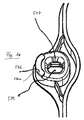
図1は、本明細書ではカセット1000とも呼ばれる、本発明による血液処理カセット1000をその主延在面の斜視平面図で示す。血液処理装置5000の、図1には示されていないアクチュエータセンサユニット514にカセット1000を結合するための、本明細書では後側又は結合側と呼ばれる提供側を見ることができ、また図1には示されていない血液処理装置5000は、本明細書では機械5000とも呼ばれる。
FIG. 1 shows a
本発明による血液処理カセット1000は、必要に応じて熱可塑性樹脂射出成形で形成される、硬質部1を備える。その弾性率の範囲は、600〜2800N/mm2であることが好ましい。使用中は、硬質部1は、図1に示されていないフィルム3で少なくとも部分的に覆われることが好ましい。
The
カセット1000は、チャンバ境界502等の血液の処理に関連する部品に加えて、例として、少なくとも1つの、好ましくは完全な縁部バー503を備える。後者は、カセット1000の除去時に、持ち上げバーとして機能する。縁部バー503は、図1に示されていない機械5000に対して、カセット1000の複数の部分をシールするのに役立つのに加えて、機械5000でカセット1000を平らに位置合わせするのに寄与することを目的として、機械5000にカセット1000を配置するのに役立つ。
The
カセット1000は更に、機械5000に対して、カセット1000を機械5000に位置決めすることに加えて、カセット1000を機械5000に一時的に固定するのに役立つことができる、第1の位置決め装置504を備える。
The
第1の位置決め装置504は、並進時にガタつきのない、カセット1000の配置の起点とされてもよい。これは、以下の第2の位置決め装置505でも説明されるように、位置決めラッチスリーブとして構成されてもよい。
The
第1の位置決め装置504は、カセット1000の縁部に、又は片側に配置されることが好ましい。これは、片側又は長手方向片側の中間に、即ち中心に配置されることが好ましい。好ましくは、血液処理に関連するカセット1000の位置決めの臨界構造(例えばセンサ及び弁点)に対して、それぞれ同じ距離又は同等の距離で配置される。
The
第2の位置決め装置505は、回転時にガタつきなく配置する位置決めラッチスリーブとして、カセット1000に設けられる。これは、第1の位置決め装置504が配置されている側とは反対側の、カセット1000の片側又は長手方向片側に配置されることが好ましい。このようにして、好適には、第1の位置決め装置504と、第2の位置決め装置505との間の距離を大きくすることが達成される。
The
第1の位置決め装置504は、持ち上げ縁部バー506を備える。これは、アクチュエータセンサユニット514に面する、少なくとも1つの挿入面取り部(即ち、挿入面取り部はアクチュエータセンサユニット514に向かって開いており、例えば漏斗状に開いている)を更に有するか、又はこのような挿入漏斗部507を有する。
The
第1の位置決め装置504又は第2の位置決め装置505の丸められた縁部は、したがってこの例示的実施形態では、挿入漏斗部507と呼ばれる。これは、カセット1000を大まかに予め位置決めするのに役立つ。
The rounded edge of the
持ち上げ縁部バー506は、強化された支持面である(支持線ではなく且つ支持点でもなく、面である)。持ち上げ縁部バー506は、これを過度の摩耗から保護するために、カセットを持ち上げるか又は取り外す際に傾けた結果生じた力を、機械側のアクチュエータセンサマット515へと導く。持ち上げ縁部バー506は、位置決め装置において、カセットを傾けて持ち上げ、取り外すことによる曲げモーメントによって、除去に必要な軸力成分が生じるように、主延在面の縁部から離間され、且つ/又は隆起されてもよい。
Lift
持ち上げ縁部バー506は、図1に示されているように、先細のファセット506aを有し、これは、持ち上げ縁部バー506の側面にあってもよい。
The lifting
持ち上げ縁部バー506は、図1bに示されているように、持ち上げ縁部バー506の、先細のファセット506aと、ほとんど水平な前方領域506cとの間に配置された、丸められた縁部506bを更に有していてもよい。
The lifting
図1a及び図1bはまた、持ち上げ縁部バー506を拡大して示し、図1aは、図1における第1の位置決め装置504の拡大を示し、図1bは、図1又は図1aにおける持ち上げ縁部バー506の拡大を示す。
1a and 1b also show an enlarged
第1の位置決め装置504及び第2の位置決め装置505は、図1の例示的実施形態では、位置決めファセット509を備える。第1の位置決め装置504用のこれらは、図1cで特によく見ることができる。したがって、図1cは、図1cを示すために反対方向からの視点で切断された、図1の部分の拡大である。図1cは、切断図であるため、挿入漏斗部507の周囲に分布する、第1の位置決め装置504の4つの位置決めファセット509のうち3つのみを示す。
The
位置決めファセット509は、少なくとも部分的に、又はそれらの上部領域において、挿入漏斗部507の一部である。これらは、この事例では、ラッチ縁部512の上方に配置されている。
The
切断図であるためここには示されていないが、2つの対向するラッチ縁部512が設けられる。 Although not shown here because of a cutaway view, two opposing latch edges 512 are provided.
本発明の幾つかの実施形態では、第1の位置決め装置504は、4つの位置決めファセット509を備える。しかしながら、第2の位置決め装置505では、図1にも見られるように、2つのみである。
In some embodiments of the present invention, the
位置決めファセット509は、(少なくとも局所的に、又は部分的に)カセット1000の主延在面に垂直な平面に延びてもよい。
The
位置決めファセット509は、位置決めピン517、518のそれぞれと局所的又は選択的に接触するのに役立つ。したがってこれらは、位置決めピン517、518を並進的に配置又は位置決めするか、或いは各位置決めピン517、518を並進変位に対してそれぞれ位置決めする。
The locating
位置決めファセット509は、例えば、挿入漏斗部507のそれぞれと直接的に境を接するか、或いは上述したように、その一部であってもよい。これらは例えば、位置決めピン517、518の、又は位置決めラッチスリーブの軸回転に沿って軸線方向に、位置決め直径522の約5〜30%でのみ延びる。これらはそれぞれ、(位置決めピン517、518の位置決め直径及び位置決め高さによって示される)位置決め領域との、軸線方向の重なりの終端部に到達する前に、フィルム平面に、又は主延在面に垂直に延びてもよい。
The
位置決めファセット509は、例えば位置決め直径522の約10〜80%で、もう一方の空間方向に(即ちフィルム平面と平行に、又は位置決めピンの対称軸に垂直に)延びる。
The
図1cに例示的に示されているように、位置決めファセット509の1つ又は全ては、上部が下部より広くてもよい。
As exemplarily shown in FIG. 1c, one or all of the
位置決めファセット509、又はそれらの延長軸線は、フィルム平面に垂直又はほぼ垂直な平面、或いは位置決めピンの対称軸とほぼ平行な平面に配置されてもよい。
The locating
ファセットの表面は、結果として、それぞれがフィルム平面にほぼ垂直に配置され得る、小さい表面になる。位置決めピン517、518の位置決めシリンダと接触して、装備位置において、プリズム状のファセット面が、プリズム構造の軸線に垂直な湾曲を有するかどうかに応じて、ファセットごとに点接触又は短い線接触が生成される。装備時及び除去時の傾きの影響をできる限り小さく維持するため、接触線は、例えば、位置決め直径522の>0〜30%の範囲の値を有する線であってもよい。この短い接触線は、位置決めピン517、518の対称軸とほぼ平行に延びる。第1の位置決め装置504は、4つの第1のファセット面509を備えていることが好ましい(しかしながら、3つ、5つ、6つ又はそれ以上のファセットがあってもよい)。第2の位置決め装置505は、本例では、2つのファセット面509(2つの位置決め装置504と505との間の結合軸に沿った並進的な配置を好適には意図的に欠いているため、厳密に2つ)を備える。
The facet surface results in small surfaces, each of which can be placed approximately perpendicular to the film plane. Depending on whether the prismatic facet surface has a curvature perpendicular to the axis of the prism structure in the installed position in contact with the positioning cylinder of the positioning pins 517, 518, point contact or short line contact is made for each facet. Generated. In order to keep the influence of the inclination at the time of installation and removal as small as possible, the contact line may be a line having a value in the range of> 0 to 30% of the
第2の位置決め装置505にある、又は第2の位置決め装置505における、厳密に2つのファセット面509は、フィルム平面にほぼ垂直に配置される平面に対して、互いに対向して平行且つミラー反転させて配置され、これにより、2つの位置決め装置504と505との間の結合線、及び2本の位置決めピン517、518の両方の対称軸を含む。
Exactly two
それぞれ第1の位置決め装置504にある2つのファセット面は、例示的実施形態では、フィルム平面にほぼ直角又は垂直に配置された平面に対して、それぞれ互いに対向して平行且つミラー反転させて配置される(したがって、第1の位置決め装置504の対称軸を含む)。図24を参照すると、フィルム平面の上面図では、本質的に最も狭い部分に、正方形の位置決め穴が見える。この正方形は、本明細書では更に、2つの位置決め装置の間の結合線に再度設けられる。この配置又は調整は、結合線が正方形の側面を直角に切断するような方法であってもよい。しかしながら、正方形の形状及びこの配置は、並進時にガタつきのないゼロ整列点として適切な機能を果たすのに必ずしも必要ではない。さらに、任意の回転配置を伴う三角形、五角形、又は六角形の位置決め穴の形状もまた可能であり、これは本発明に包含される。
The two facet surfaces, each in the
位置決めファセット509は、挿入漏斗部507の一部であってもよい。これらは、図1cの拡大図にも見られるように、少なくとも部分的に、好適には挿入漏斗部507の上部領域に配置される。
The
図1cでは、使用中にアクチュエータセンサマット516に面するカセット1000の側面が、上部に配置される。カセット1000の側面、又は使用中に機械のドアに面するカセット1000の側面は、下部に配置される。
In FIG. 1c, the side of the
図1cに見られるように、幾つかの例示的実施形態における位置決めファセット509は、(複数の)ラッチ縁部512の上方に配置される。上方とは、本明細書ではアクチュエータセンサマット516により近い方として理解され、下方とは、カセットの背面又は機械のドアに向かう、より遠い方として理解されるべきである。
As seen in FIG. 1 c, the
ラッチ縁部512は、本発明の好ましい例示的実施形態では、直線状か又は湾曲した縁部になるように適合又は具体化される。この設計により、細長いか又は(広い)面接触とは対照的な、図1には示されていない位置決めピン517、518のうちの1本の、ラッチ直径521との点接触がほぼ可能になる。
The
第1の位置決め装置504及び/又は第2の位置決め装置505は、本発明による幾つかの例示的実施形態では、位置決めに関与するだけでなく、機械5000へのカセット1000のラッチにも関与するか又はこれに寄与し、したがって、このような実施形態では、これらは位置決めラッチ装置とも呼ばれる場合がある。
Whether the
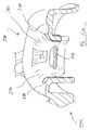
図2は、図1のカセット1000をドア側の斜視平面図で示す。ドア側は、図2には示されていない機械のドア524によって、必要に応じて押圧するのに役立つ。これは、結合側の反対側に位置し、前側とも呼ばれる場合がある。
FIG. 2 shows the
図2は、これも単に必要に応じて本明細書に示される、別の完全な縁部バー508を示す。これは、機械のドア524による押圧の効果を伝達するための(平面であることが好ましい)面として機能するだけでなく、カセット1000を強化するため、且つ第1の位置決め装置504及び/又は第2の位置決め装置505の強化された結合のための面としても機能するので、多機能とされてもよい。また、装備及び除去の力の伝達、並びに取り外すために使用者がカセット1000に触れる(任意の)部分からの、力経路の伝達にも役立つ場合があり、発生した力は、ここから第1の位置決め装置504及び/又は第2の位置決め装置505を介して、カセット1000及び位置決めピン517、518の中へ導入され得る。
FIG. 2 shows another
図3は、図2のGの詳細図を示す。 FIG. 3 shows a detailed view of G in FIG.
図4は、図2のFの詳細図を示す。 FIG. 4 shows a detailed view of F of FIG.
第1の位置決め装置504及び/又は第2の位置決め装置505の部品であるスナップインピンは、参照符号510で図に示されている。各位置決め装置504、505用に、好ましくは少なくとも2つのスナップインつまみ510が設けられ、好ましくは互いに対向して配置される。
A snap-in pin that is part of the
スナップインつまみ510は、用途のために弾性的に曲げられるように適合されてもよい。切り込み511によって、互いに離間されてもよく、これは、スナップインつまみ510の特定の曲げ柔軟性に寄与する。
The snap-in
各スナップインつまみ510は、少なくとも1つの、又は厳密に1つのラッチ縁部512を有する。後者は、主延在面と平行な第1の平面に延び、好ましくは局所的に、特に、ラッチの保持力が変化することのない、位置決めピン517、518に対する移動能力を可能にするために、更に位置決めファセット509の位置決め力が確実に優先されるように、カセット1000の主延在面と平行な平面に延びる。
Each snap-in
本発明による好ましい実施形態によれば、主延在面に垂直な第2の平面では、ラッチ縁部512は、湾曲した縁部であるか、又はこれを有する。この形状は、位置決めピン517、518の同様に湾曲した溝との線接触を可能にし、これによって、装備及び除去手順における摩擦を最小限にする役割を果たす。
According to a preferred embodiment according to the present invention, in a second plane perpendicular to the main extending surface, the
図5は、機械5000のアクチュエータセンサユニット514を、主延在面の斜視平面図で示す。
FIG. 5 shows the
図6は、図5のHの詳細図を斜視図で示す。 FIG. 6 shows a detailed view of H in FIG. 5 in a perspective view.
図7は、図5のHの詳細図を断面図で示す。 FIG. 7 shows a detailed view of H in FIG. 5 in a cross-sectional view.
図において、参照符号514は、機械5000のアクチュエータセンサユニット514を示し、515は、ユニット514のアクチュエータセンサマットを示す。アクチュエータセンサマット515は、必要な場合にのみ設けられ、且つ、カセット1000に好ましくは平らに結合するために、これもまた平らな状態で構成される。
In the figure,
516は、アクチュエータセンサプレートを示す。これは、第1の位置決めピン517及び第2の位置決めピン518用のより硬質な基準体及び基材である。
第1の位置決めピン517は、第1の位置決め装置504にラッチするために設けられ、第2の位置決めピン518は、第2の位置決め装置505にラッチするために設けられる。
The
本発明による幾つかの例示的実施形態では、第1の位置決めピン517又は第2の位置決めピン518は、以下の特徴を有することができ、これは互いに独立して提供されてもよい。言い換えれば、
−回転対称な部品として具体化されてもよく、費用対効果が高く、精密、且つ、組み立てが簡便である。
−硬質で耐摩耗性の材料(セラミック、鋼等)で作られてもよい。
−研磨面を備えていてもよい(摩擦の最小化、清浄性、傾きの低減)。
−同一の部品になるように適合されてもよい(費用対効果が高く、入れ替わりのリスクがない)。
−図6に例示的に示されているように、第1の位置決め装置504及び第2の位置決め装置505に対する真っ直ぐな、或いは斜め又は傾いた相対移動による摩擦を最小限にするため、並びに位置決め装置504、505へのねじ込みの最適化のために、丸みを帯びた移行部519、及び好ましくは強靭な、丸められた前方領域縁部520を有していてもよい。
−位置決め直径522未満であるか、又はより小さいラッチ直径521を有してもよい。これによってねじ込みを最適化し、装備及び除去時の傾きのリスクを低減する。
−位置決め直径522の0.1〜0.5倍の範囲内の位置決め高さ523を有していてもよい。これにより、装備及び除去中に、好適には、最大の傾き可能な傾き角度を制限するのに役立つ。
In some exemplary embodiments according to the present invention, the
-It may be embodied as a rotationally symmetric part, cost-effective, precise and easy to assemble.
-It may be made of a hard and wear resistant material (ceramic, steel, etc.).
-It may have a polished surface (minimization of friction, cleanliness, reduction of tilt).
-May be adapted to be the same part (cost-effective, no replacement risk).
-As shown in an exemplary manner in Fig. 6, to minimize friction due to straight or oblique or inclined relative movement with respect to the
-It may have a
-You may have the
傾きの制限は、好適には、本発明による幾つかの実施形態で行われ、傾き角度は、除去するために傾けながら動かしている際に徐々に増加する。同時に持ち上げることによって、位置決め装置は、位置決めピンに対して、傾き角度を増しながら平行に動かされる。位置決めピン517、518の位置決め高さ523が制限されているので、対応する位置決め装置504、505は、位置決めピン517、518の位置決め直径522から係合が外れ、位置決めピン517、518は、位置決めファセット509の範囲内において、傾き角が小さい傾き範囲に対して、既に臨界でない範囲にある。
Tilt limiting is preferably done in some embodiments according to the present invention, where the tilt angle gradually increases as it is tilted to remove. By lifting at the same time, the positioning device is moved parallel to the positioning pin while increasing the tilt angle. Since the
図8は、全くの任意選択である機械のドアを欠いた、装備した状態のカセット及び機械の部分の平面図を示す。 FIG. 8 shows a top view of the loaded cassette and machine part, with the machine door completely devoid of options.
図9は、図8のH−Hの線に沿った断面を示し、図8に比べて、任意選択の機械のドア524が補われており、押圧された状態が示されている。
FIG. 9 shows a cross-section along the line HH in FIG. 8, with the
任意選択の機械のドア524は、カセット1000を押圧するのに役立つだけでなく、カセット1000が、1個所でねじれるか又は曲がった状態で置かれた場合に、平面に配置するのに役立つ。この配置は、完全な縁部バー508によって、場合によっては更に、任意選択の平面支持ゾーン525及び526によって、アクチュエータセンサユニット514で行われる。
The
カセット1000は、血液処理中に、アクチュエータセンサマット515上で摩擦で閉じることによって配置される。これにより、機械的又は流体的な力がカセット1000又は関連する結合ホースに当たるときでも、カセット1000の位置合わせが確実に維持される。
本発明による幾つかの例示的実施形態では、押圧された状態で、カセット1000に接触する機械のドア524の支持面は全て、カセット1000の主平面と平行に配置される。これにより好適には、位置決めピン517及び518を介したカセット1000単独の位置決めが確実になる。
In some exemplary embodiments according to the present invention, all of the support surfaces of the
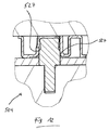
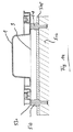
図10は、第1の位置決め装置504を、図8のS−Sの線に沿った断面図で詳細に示す。
FIG. 10 shows the
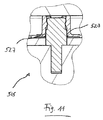
図11は、第2の位置決め装置505を、図8のK−Kの線に沿った断面図で詳細に示す。
FIG. 11 shows in detail the
図12及び図13は、図8のH−Hの線に沿った断面図で、第1の位置決め装置504及び第2の位置決め装置505の詳細図を示す。
12 and 13 are cross-sectional views taken along the line HH in FIG. 8 and show detailed views of the
図10〜図12のそれぞれにおいて、第1の位置決め装置504及び第2の位置決め装置505は、位置決めピン517及び518によってラッチされる。
In each of FIGS. 10 to 12, the
図10は、第1の位置決め装置504を、図8のS−Sの切断方向で示し、2本の短い対向する接触線又は接触線部527は、(上部及び下部のカセットの縁部バーまでの、持ち上げ縁部の距離が非常に長いため)それぞれ同じ長さを有し、且つ比較した場合、類似の長さを有する。
FIG. 10 shows the
図11は、図10の部分に類似した部分を示す。図10に対して述べたことは、図11にも同様に当てはまる。 FIG. 11 shows a portion similar to that of FIG. What has been said for FIG. 10 applies equally to FIG.
図12は、切断部H−Hに沿った第1の位置決め装置の断面を示し、これは特に、図20〜図23に示されているように、装備及び除去中により大きい傾きが導入されることによって、好ましくない影響を受ける。図12では、右側にある長い右の線接触部527よりも短い、左側にある左の線接触部527が見られ、これは、図26による位置決め狭所の、反転され且つ予測された、予め傾けられた配置を介して、アクチュエータセンサマット515から離れて配置される。
FIG. 12 shows a cross-section of the first positioning device along the cut HH, which in particular introduces a greater inclination during installation and removal, as shown in FIGS. 20-23. Are adversely affected. In FIG. 12, there is seen a
図10〜図12では、線接触部527又は線分は、図24にも見られるように、位置決め直径において好ましくは点状に、位置決めピン517、518に接触する。
10-12, the
位置決めピン517、518の線接触部527と位置決め直径522との間の通路幅の公差状況は、好ましくは、具体的にはガタつきのない配置で始まって、カセット1000の位置決めラッチが完了するまで、常にガタつきがないか又はゼロバックラッシュである(即ち遊びがない)ように選択される。これは、第1の位置決め装置504の全ての(この事例では4つの)位置決めファセット509、及び第2の位置決め装置505の(ここでは2つの)位置決めファセット509の、点状又は短い線状の配置のためである。比較的硬い位置決めピン517、518が、比較的柔らかい位置決めファセット509に押し付けられる場合は、対向する位置決めファセット同士の間の距離によって測定された位置決めピン517、518の直径は、少なくとも部分的に弾性に、且つ部分的に可塑性に変形する、余分なより柔らかい面を有することが好ましい。これが変形することによって、点接触が円形又は楕円形の接触面になり、線接触は面接触になる。ラッチされた状態でのガタつきのなさは、常に保証されて片側に残存する。除去中の押圧力ひいては摩擦力は、熱可塑性樹脂の弾性率が低い(例えば1800N/mm2)ため、また、部分的な塑性変形のために、もう一方の側で十分に低いまま残存し、その結果、傾き中に材料の破損が引き起こされることはない。
The tolerance situation of the passage width between the
この膨張するプラスチック部品は、処理の行程で更に膨張するため、除去が容易になる。更に、摩擦で閉じることができる機械のドア524によって、処理中のカセット1000の変位が確実に防止される。
This expanding plastic part expands further during the process, making it easy to remove. In addition, a
第2の位置決め装置505の丸みを帯びた移行部又はスプリット528には遊びがあり、この方向への位置決めを防止する。
There is play in the rounded transition or split 528 of the
第2の位置決め装置505の長手方向軸線は、カセット1000の回転の可能性を最大まで制限するために、第1の位置決め装置504の貫通孔又は貫通開口の中心に向けられる。同時に、長手方向軸線は、カセット1000の縁部バー508までのほぼ最短距離の方向を指す。
The longitudinal axis of the
スナップインつまみ510同士の間の切り込み又はスリット511もまた、好ましくは第1の位置決め装置504と第2の位置決め装置505との間の結合軸又は結合線に対称に配置され、傾き移動の自由度を増すように機能する。
The cuts or slits 511 between the snap-in
図14は、装備工程の第1の手順であって、カセット1000の配置を示す。参照符号3は、フィルムを示す。
FIG. 14 shows the arrangement of the
図15は、装備工程の第2の手順であって、ねじ込みの開始を示す。 FIG. 15 shows the second procedure of the installation process, showing the start of screwing.
図16は、装備工程の第3の手順であって、片側でのねじ込みの片側の完了を示す。 FIG. 16 shows the third step of the installation process, the completion of screwing on one side.
図17は、装備工程の第4の手順であって、両側でのねじ込みの完了を示す。 FIG. 17 shows the fourth procedure of the installation process, showing the completion of screwing on both sides.
図18は、装備工程の第5の手順であって、片側での位置決めラッチの完了を示す。 FIG. 18 shows the fifth procedure of the installation process, and the completion of the positioning latch on one side.
図19は、装備工程の第6の手順であって、両側での位置決めラッチの完了を示す。 FIG. 19 shows the sixth procedure of the installation process, and the completion of the positioning latches on both sides.
以下で更に詳しく説明される、前述の図に示された装備工程では、位置決めピン517、518の平らな前方領域は、それに応じて余裕を持って測定されたカセット1000の平面及び平らな前方領域と関連して、両方の位置決め装置504、505の周囲に、人間工学的に好都合な、許容できる横ずれ530を可能にし、このずれは、破損の恐れのないカセット1000の手動による配置では、好ましくは位置決め直径522の0.5〜2.5倍であることが好ましい。
In the mounting process shown in the previous figures, which will be described in more detail below, the flat front region of the positioning pins 517, 518 corresponds to the flat and flat front region of the
ねじ込みの開始時に、横ずれ531は、対応する挿入面取り部507のために、好ましくは位置決め直径522の0.1〜0.2倍以内であり、これは、面取り部の縁部で、Z方向への接近移動を速やかに開始して中心に到達するずっと前に、作業者にねじ込みが見えるので、人間工学的に好ましく、次に、更なるねじ込み工程が、面取り部507によってガイドされる。
At the start of screwing, the lateral displacement 531 is preferably within 0.1 to 0.2 times the
片側でのねじ込みの完了後に、そのラッチ縁部512が位置決めピン517、518の丸められた前方領域縁部520に接触する程度に、位置決め装置504、505のうちの1つがねじ込まれる一方で、もう一方の位置決め装置504、505は、そのねじ込みがまだ始まっていないか、若しくはまだこれを完了していない。位置決めピン517、518の高さの合計と、位置決め高さ523との間の高さの相違に関連して選択された、位置決め装置504と位置決め装置505との間の距離のために、カセット1000の主延在面と、機械5000の主延在面との間の最大角度傾斜532は、約1〜3度である。幾何学的設計に関連して、「位置決めピンの丸められた前側」、「位置決め直径未満」のスナップイン直径、及び「位置決め装置の挿入面取り部」が傾いていることによって、ねじ込みが行われている間は、動きの妨害又は材料の過負荷が防止される。
After completion of screwing on one side, one of the
ラッチの開始時に、位置決め装置504、505の両方は、ある程度まで位置決めピン517、518の中に挿入され、2つの主延在面(片側はカセット1000、もう一方はアクチュエータセンサマット515)の間の距離533は、位置決め点の距離の(わずか)約0.02〜0.04倍以上である。その後のラッチが任意の順序及び角度位置を経ても、約1.5度より大きい傾き角534は達成され得ない。材料及び幾何学的な選択に関連してもたらされた、この低い傾き角534は、カセット1000の材料の過大応力につながる、いかなる傾動力ももたらさない。このような傾動力は、同時に、測定のあらゆる公差位置において、目標とする約50Nの最大スナップイン力を越えないことを示す。
At the beginning of the latch, both positioning
図20は、除去の工程中に、第2の位置決め装置505でラッチが解除されるか又はスナップが外れた臨界の瞬間を示す。
FIG. 20 shows the critical moment during the removal process when the
図21は、除去の工程中に、第1の位置決め装置504でラッチが解除された臨界の瞬間を示す。
FIG. 21 shows the critical moment when the latch is released by the
図22は、図20の部分Oを詳細に示す。 FIG. 22 shows part O of FIG. 20 in detail.
図23は、図21の部分Pを詳細に示す。 FIG. 23 shows part P of FIG. 21 in detail.
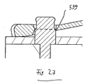
前述の図に表され、以下で詳細に説明される除去の工程では、2つの位置決め装置504、505の選択された測定値に基づき、最大約10度の角度範囲535、536でラッチの解除が行われる。ラッチ解除の瞬間にこの傾き角が達成される場合がある、最悪の場合の除去工程が、図20及び図21に示されている。
The removal process represented in the previous figure and described in detail below, based on the selected measurements of the two
位置決め装置505では、スロット様の貫通孔又は開口が、スナップインつまみ510同士の間の切り込み511に関連して、且つ持ち上げ縁部の距離537、並びに高さ及び径比に関連して、傾き状況538が達成されるのを防止する。
In the
第1の位置決め装置504では、位置決め貫通孔の傾いた配置541が、スナップインつまみ510同士の間の切り込み511に関連して、且つ持ち上げ縁部の距離537、並びに高さ及び径比に関連して、傾き状況539が達成されるのを防止する。平らに具体化された、必要に応じて設けられるつまみ540は、スナップインつまみ510のように曲げられるので、臨界の傾きを引き起こすことはない。
In the
図24は、単に例示的な寸法であって、ここでは位置決めピンを受けた、第1の位置決め装置504及び第2の位置決め装置505を概略図で示す。
FIG. 24 schematically shows a
図25は、スナップインつまみ510を欠いた傾きを概略図で示す。
FIG. 25 is a schematic view showing an inclination without the snap-in
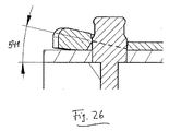
図26は、装備位置の第1の位置決め装置504を概略図で示す。
FIG. 26 schematically shows the
図27は、ラッチが解除された臨界の瞬間の第2の位置決め装置505を概略図で示す。
FIG. 27 schematically shows the
持ち上げ縁部の距離537、及び位置決め高さ523に応じて、第1の位置決め装置504の貫通孔又は開口のピッチ角541は、好適には約9〜14度である。ここでは、スナップインつまみ510のラッチ解除の瞬間は、位置決めピン517、518の位置決め直径522からの、位置決めファセット509の係合解除539とほぼ一致し、持ち上げて除去するように動かしている間に、機械の高さに突出した2つのファセットの距離は継続的に拡大し、常に位置決め直径522より大きいままとなる。
Depending on the
1000 血液処理カセット、流体カセット又はカセット
1 硬質部
3 フィルム
502 チャンバ境界
503 縁部バー
504 第1の位置決め装置
505 第2の位置決め装置
506 持ち上げ縁部バー
506a 先細のファセット
506b 丸められた縁部
506c 前方領域
507 挿入面取り部又は挿入漏斗部
508 閉じられた縁部バー
509 位置決めファセット
510 スナップインつまみ
511 切り込み
512 ラッチ縁部
514 アクチュエータセンサユニット
515 アクチュエータセンサマット
516 アクチュエータセンサプレート
517 第1の位置決めピン
518 第2の位置決めピン
519 移行部
520 前方領域の縁部
521 スナップイン直径
522 位置決め直径
523 位置決め高さ
524 機械のドア
525 支持ゾーン
526 支持ゾーン
527 線接触部
528 丸みを帯びた移行部
530 横ずれ
531 横ずれ
532 最大角度傾斜
533 距離
534 傾き角
535 角度領域
536 角度領域
537 持ち上げ縁部距離
538 傾き状態
539 傾き状態
540 ピン又はつまみ
541 傾いた配置
5000 機械又は血液処理装置
1000 Blood processing cassette, fluid cassette or cassette 1
Claims (18)
前記硬質部(1)は、必要に応じて前記流体カセットの第1及び第2の対向する側に配置されるか又はそこに取り付けられる、少なくとも1つの第1の位置決め装置(504)、及び第2の位置決め装置(505)を備える、医療用流体カセット。 A medical fluid having a cassette body embodied as a hard part (1) and, if necessary, a film (3) coupled to the hard part (1) and at least partially covering the hard part (1) A cassette, in particular a blood treatment cassette (1000),
The rigid part (1) is arranged on or attached to first and second opposing sides of the fluid cassette as required, at least one first positioning device (504), and a first A medical fluid cassette comprising two positioning devices (505).
Applications Claiming Priority (3)
| Application Number | Priority Date | Filing Date | Title |
|---|---|---|---|
| DE102014103492.9A DE102014103492A1 (en) | 2014-03-14 | 2014-03-14 | Fluid cartridge with tilt-tolerant centering latch and blood treatment device |
| DE102014103492.9 | 2014-03-14 | ||
| PCT/EP2015/055299 WO2015136077A1 (en) | 2014-03-14 | 2015-03-13 | Fluid cassette having a tilt-tolerant centering locking, and blood treatment device |
Publications (2)
| Publication Number | Publication Date |
|---|---|
| JP2017507746A true JP2017507746A (en) | 2017-03-23 |
| JP6594890B2 JP6594890B2 (en) | 2019-10-23 |
Family
ID=52669623
Family Applications (1)
| Application Number | Title | Priority Date | Filing Date |
|---|---|---|---|
| JP2016557022A Active JP6594890B2 (en) | 2014-03-14 | 2015-03-13 | Fluid cassette having positioning latch and blood processing apparatus with improved tilt tolerance |
Country Status (13)
| Country | Link |
|---|---|
| US (2) | US10471196B2 (en) |
| EP (1) | EP3116563B1 (en) |
| JP (1) | JP6594890B2 (en) |
| KR (1) | KR102433088B1 (en) |
| CN (1) | CN106102792B (en) |
| AU (1) | AU2015228756B2 (en) |
| CA (1) | CA2941195C (en) |
| DE (1) | DE102014103492A1 (en) |
| ES (1) | ES2720349T3 (en) |
| MX (1) | MX2016011746A (en) |
| PL (1) | PL3116563T3 (en) |
| TR (1) | TR201904782T4 (en) |
| WO (1) | WO2015136077A1 (en) |
Cited By (1)
| Publication number | Priority date | Publication date | Assignee | Title |
|---|---|---|---|---|
| WO2024004345A1 (en) * | 2022-06-27 | 2024-01-04 | 日機装株式会社 | Blood purification device |
Families Citing this family (3)
| Publication number | Priority date | Publication date | Assignee | Title |
|---|---|---|---|---|
| DE102015001406B3 (en) * | 2015-02-04 | 2016-07-14 | Fresenius Medical Care Deutschland Gmbh | Cassette module for a differential flow meter and differential flow meter |
| DE102017101730A1 (en) * | 2017-01-30 | 2018-08-02 | Fresenius Medical Care Deutschland Gmbh | New shock protection device for medical fluid-carrying cassette and cassette |
| US20220080091A1 (en) * | 2020-09-16 | 2022-03-17 | Fresenius Medical Care Holdings, Inc. | Dialysis machine with intelligent load monitoring |
Citations (4)
| Publication number | Priority date | Publication date | Assignee | Title |
|---|---|---|---|---|
| JP2012520089A (en) * | 2009-03-10 | 2012-09-06 | フレゼニウス メディカル ケア ドイッチェランド ゲゼルシャフト ミット ベシュレンクテル ハフツング | Sealing means, and apparatus and method for sealing a volume of a medical processing device to other volumes |
| JP2012520090A (en) * | 2009-03-10 | 2012-09-06 | フレゼニウス メディカル ケア ドイッチェランド ゲゼルシャフト ミット ベシュレンクテル ハフツング | Apparatus for connecting external function means to apparatus, apparatus including similar apparatus, and connection method |
| JP2012524563A (en) * | 2009-04-23 | 2012-10-18 | フレゼニウス メディカル ケア ドイッチェランド ゲゼルシャフト ミット ベシュレンクテル ハフツング | External function means, blood processing apparatus and method for receiving external function means according to the present invention |
| US20130248629A1 (en) * | 2012-03-16 | 2013-09-26 | Fresenius Medical Care Deutschland Gmbh | Medical treatment apparatus, device for supplying medical fluids, and apparatus for filling a device for supplying medical fluids |
Family Cites Families (76)
| Publication number | Priority date | Publication date | Assignee | Title |
|---|---|---|---|---|
| US4436620A (en) | 1977-05-09 | 1984-03-13 | Baxter Travenol Laboratories, Inc. | Integral hydraulic circuit for hemodialysis apparatus |
| DE2838414C2 (en) | 1978-09-02 | 1984-10-31 | Fresenius AG, 6380 Bad Homburg | Device for hemodialysis and for withdrawing ultrafiltrate |
| IL64001A0 (en) | 1981-10-06 | 1982-01-31 | Elmar Medical Systems Ltd | Blood treatment system |
| US4479762A (en) | 1982-12-28 | 1984-10-30 | Baxter Travenol Laboratories, Inc. | Prepackaged fluid processing module having pump and valve elements operable in response to applied pressures |
| US4666598A (en) | 1985-06-25 | 1987-05-19 | Cobe Laboratories, Inc. | Apparatus for use with fluid flow transfer device |
| US4768547A (en) * | 1985-11-18 | 1988-09-06 | Critikon, Inc. | Parenteral solution pump assembly |
| FR2594340A1 (en) | 1986-02-14 | 1987-08-21 | Pf Medicament | Improved dialysis device |
| US5486286A (en) | 1991-04-19 | 1996-01-23 | Althin Medical, Inc. | Apparatus for performing a self-test of kidney dialysis membrane |
| US5336165A (en) | 1991-08-21 | 1994-08-09 | Twardowski Zbylut J | Artificial kidney for frequent (daily) Hemodialysis |
| US5441636A (en) | 1993-02-12 | 1995-08-15 | Cobe Laboratories, Inc. | Integrated blood treatment fluid module |
| ATE204770T1 (en) | 1993-03-03 | 2001-09-15 | Deka Products Lp | CASSETTE FOR PERIOTONEAL DIALYSIS |
| FR2702962B1 (en) | 1993-03-22 | 1995-04-28 | Hospal Ind | Device and method for controlling the balance of fluids on an extracorporeal blood circuit. |
| US5462416A (en) | 1993-12-22 | 1995-10-31 | Baxter International Inc. | Peristaltic pump tube cassette for blood processing systems |
| US5591344A (en) | 1995-02-13 | 1997-01-07 | Aksys, Ltd. | Hot water disinfection of dialysis machines, including the extracorporeal circuit thereof |
| EP1671665A1 (en) | 1995-06-07 | 2006-06-21 | Gambro, Inc., | Apheresis system |
| AT403962B (en) * | 1996-10-30 | 1998-07-27 | Avl Verbrennungskraft Messtech | DEVICE FOR CARRYING OUT ELECTROCHEMICAL AND / OR OPTICAL MEASURING PROCEDURES IN LIQUIDS |
| AU5458898A (en) | 1996-11-22 | 1998-06-10 | Therakos, Inc. | Integrated cassette for controlling fluid having an integral filter |
| US5759502A (en) * | 1997-01-31 | 1998-06-02 | Sterilization Cassette Systems, Inc. | Instrument cassette having a mechanism to prevent lateral movement of an instrument support relative to an instrument support holder |
| AU3273201A (en) | 1997-02-14 | 2001-06-04 | Nxstage Medical, Inc. | Fluid processing systems and methods using extracorporeal fluid flow panels oriented within a cartridge |
| DE19837667A1 (en) | 1998-08-19 | 2000-03-02 | Fresenius Medical Care De Gmbh | Multifunction sensor |
| US6695803B1 (en) | 1998-10-16 | 2004-02-24 | Mission Medical, Inc. | Blood processing system |
| US6481980B1 (en) | 1999-09-03 | 2002-11-19 | Baxter International Inc. | Fluid flow cassette with pressure actuated pump and valve stations |
| US7169352B1 (en) | 1999-12-22 | 2007-01-30 | Gambro, Inc. | Extracorporeal blood processing methods and apparatus |
| US6497676B1 (en) | 2000-02-10 | 2002-12-24 | Baxter International | Method and apparatus for monitoring and controlling peritoneal dialysis therapy |
| AU2001261080A1 (en) | 2000-05-02 | 2001-11-12 | Vasca, Inc. | Methods and devices for draining fluids in and out of the body |
| DE10042324C1 (en) | 2000-08-29 | 2002-02-07 | Fresenius Medical Care De Gmbh | Blood dialysis device has feed line provided with 2 parallel branches for single needle and dual needle operating modes |
| DE10046651A1 (en) | 2000-09-20 | 2002-04-04 | Fresenius Medical Care De Gmbh | Valve |
| DE10053441B4 (en) | 2000-10-27 | 2004-04-15 | Fresenius Medical Care Deutschland Gmbh | Disposable cassette with sealing membrane and valve actuator therefor |
| US6471855B1 (en) | 2000-11-22 | 2002-10-29 | Baxter International Inc. | Cassette with integral separation device |
| US6515125B1 (en) * | 2001-03-09 | 2003-02-04 | Bayer Corporation | Liquid partially trimerized polyisocyanates based on toluene diisocyanate and diphenylmethane diisocyanate |
| ITTO20010583A1 (en) | 2001-06-15 | 2002-12-15 | Gambro Dasco Spa | BLOOD CIRCULATION CIRCUIT FOR A DIALYSIS MACHINE AND RELATED DIALYSIS MACHINE. |
| CA2453022C (en) | 2001-07-03 | 2008-06-17 | Jms Co., Ltd. | Blood dialysis apparatus having convenient controlling unit |
| US6878105B2 (en) | 2001-08-16 | 2005-04-12 | Baxter International Inc. | Red blood cell processing systems and methods with deliberate under spill of red blood cells |
| DE10143137C1 (en) | 2001-09-03 | 2003-04-17 | Fresenius Medical Care De Gmbh | Measuring device and method for determining parameters of medical liquids and method for calibrating such a device |
| GB0127224D0 (en) | 2001-11-13 | 2002-01-02 | Glaxosmithkline Biolog Sa | Novel compounds |
| SE525132C2 (en) | 2001-11-23 | 2004-12-07 | Gambro Lundia Ab | Method of operation of dialysis device |
| US20030220607A1 (en) | 2002-05-24 | 2003-11-27 | Don Busby | Peritoneal dialysis apparatus |
| DE10224750A1 (en) | 2002-06-04 | 2003-12-24 | Fresenius Medical Care De Gmbh | Device for the treatment of a medical fluid |
| AU2003254565A1 (en) | 2002-09-11 | 2004-05-04 | Fresenius Medical Care Deutschland Gmbh | Method for returning blood from a blood treatment device, and device for carrying out this method |
| US7942861B2 (en) | 2002-10-22 | 2011-05-17 | Baxter International Inc. | Fluid container with access port and safety cap |
| US7507226B2 (en) | 2002-10-22 | 2009-03-24 | Baxter International Inc. | Access port with safety tab and fluid container employing same |
| US7264607B2 (en) | 2003-03-21 | 2007-09-04 | Gambro Lundia Ab | Circuit for extracorporeal blood circulation |
| CA2436372A1 (en) | 2003-08-04 | 2005-02-04 | Luc Mainville | Sealing assembly for a cylinder head |
| US20050049539A1 (en) | 2003-09-03 | 2005-03-03 | O'hara Gerald P. | Control system for driving fluids through an extracorporeal blood circuit |
| US8029454B2 (en) | 2003-11-05 | 2011-10-04 | Baxter International Inc. | High convection home hemodialysis/hemofiltration and sorbent system |
| DE102004011461B4 (en) | 2004-03-09 | 2007-06-28 | Ppa Technologies Ag | Device for changing and / or docking functional modules |
| DE102004023080B4 (en) | 2004-05-11 | 2009-01-15 | Fresenius Medical Care Deutschland Gmbh | Method and device for monitoring the supply of substitution fluid during extracorporeal blood treatment |
| CN100523502C (en) | 2004-05-14 | 2009-08-05 | 弗雷森纽斯医疗护理德国有限责任公司 | Roller pump |
| US7476209B2 (en) | 2004-12-21 | 2009-01-13 | Therakos, Inc. | Method and apparatus for collecting a blood component and performing a photopheresis treatment |
| US20060195064A1 (en) | 2005-02-28 | 2006-08-31 | Fresenius Medical Care Holdings, Inc. | Portable apparatus for peritoneal dialysis therapy |
| US7935074B2 (en) | 2005-02-28 | 2011-05-03 | Fresenius Medical Care Holdings, Inc. | Cassette system for peritoneal dialysis machine |
| EP1898974A1 (en) | 2005-05-19 | 2008-03-19 | Vasogen Ireland Limited | Verification method&system for medical treatment |
| US7727371B2 (en) * | 2005-10-07 | 2010-06-01 | Caliper Life Sciences, Inc. | Electrode apparatus for use with a microfluidic device |
| KR200408394Y1 (en) * | 2005-11-28 | 2006-02-08 | 강민희 | A snap button |
| US7556611B2 (en) | 2006-04-18 | 2009-07-07 | Caridianbct, Inc. | Extracorporeal blood processing apparatus with pump balancing |
| US7484769B2 (en) | 2006-07-17 | 2009-02-03 | Alcon, Inc. | Connector to cassette interface system |
| US8926550B2 (en) | 2006-08-31 | 2015-01-06 | Fresenius Medical Care Holdings, Inc. | Data communication system for peritoneal dialysis machine |
| US20080058712A1 (en) | 2006-08-31 | 2008-03-06 | Plahey Kulwinder S | Peritoneal dialysis machine with dual voltage heater circuit and method of operation |
| WO2008053262A1 (en) | 2006-10-30 | 2008-05-08 | Gambro Lundia Ab | Medical fluid circuit unit |
| KR101111010B1 (en) | 2007-02-15 | 2012-02-16 | 아사히 카세이 쿠라레 메디칼 가부시키가이샤 | Blood purification system |
| JP5217355B2 (en) | 2007-03-30 | 2013-06-19 | 株式会社ジェイ・エム・エス | Blood purification control device |
| DE102007018362A1 (en) | 2007-04-18 | 2008-10-30 | Fresenius Medical Care Deutschland Gmbh | Method for preparing a treatment machine and treatment machine |
| DE102007042964A1 (en) | 2007-09-10 | 2009-03-19 | Fresenius Medical Care Deutschland Gmbh | Apparatus and method for treating a medical fluid and medical cassette |
| US9044542B2 (en) * | 2007-12-21 | 2015-06-02 | Carticept Medical, Inc. | Imaging-guided anesthesia injection systems and methods |
| RU2486922C2 (en) | 2008-11-28 | 2013-07-10 | Терумо Кабусики Кайся | Blood container system and cassette |
| US9374307B2 (en) * | 2009-01-27 | 2016-06-21 | Telefonaktiebolaget Lm Ericsson (Publ) | Group session management for policy control |
| DE102009008346B4 (en) | 2009-02-11 | 2014-11-13 | Fresenius Medical Care Deutschland Gmbh | A method of removing blood from an extracorporeal blood circuit for a treatment device after completion of a blood treatment session and apparatus for performing the same |
| DE102009024469A1 (en) | 2009-06-10 | 2011-01-05 | Fresenius Medical Care Deutschland Gmbh | Valve device for injecting e.g. drugs into blood conducting passages of blood treatment cassette of blood treatment apparatus for extracorporeal blood treatment, has valve insert formed so that insert is switched among three valve states |
| DE102009036101A1 (en) | 2009-08-04 | 2011-02-24 | Fresenius Medical Care Deutschland Gmbh | Connecting device for connecting at least one external functional device with an arrangement, arrangement comprising such a connecting device and method for connecting |
| DE102010003642A1 (en) | 2010-03-15 | 2011-09-15 | Fresenius Medical Care Deutschland Gmbh | Cassette with a sensor for determining the difference between a first and a second liquid flow |
| DE102010032181A1 (en) | 2010-07-23 | 2012-01-26 | Fresenius Medical Care Deutschland Gmbh | Coupling device, connector, medical device function, medical treatment device and method |
| US9624915B2 (en) * | 2011-03-09 | 2017-04-18 | Fresenius Medical Care Holdings, Inc. | Medical fluid delivery sets and related systems and methods |
| FR2986524B1 (en) * | 2012-02-06 | 2018-03-02 | Chryso | ADJUVANT ACCELERATOR OF RECEPTACLE WITH IMPROVED STABILITY |
| US10010886B2 (en) * | 2012-08-28 | 2018-07-03 | Fenwal, Inc. | Spring-open sheeting for fluid processing cassette |
| DE112013004623T5 (en) * | 2012-09-22 | 2015-06-03 | Brandon Bransgrove | Cassette and analyzer |
| WO2014121216A1 (en) * | 2013-02-04 | 2014-08-07 | Siemens Healthcare Diagnostics Inc. | Instrument docking apparatus, systems, and methods |
-
2014
- 2014-03-14 DE DE102014103492.9A patent/DE102014103492A1/en not_active Ceased
-
2015
- 2015-03-13 CA CA2941195A patent/CA2941195C/en active Active
- 2015-03-13 CN CN201580012845.5A patent/CN106102792B/en active Active
- 2015-03-13 US US15/126,244 patent/US10471196B2/en active Active
- 2015-03-13 ES ES15709507T patent/ES2720349T3/en active Active
- 2015-03-13 KR KR1020167028720A patent/KR102433088B1/en active IP Right Grant
- 2015-03-13 MX MX2016011746A patent/MX2016011746A/en active IP Right Grant
- 2015-03-13 TR TR2019/04782T patent/TR201904782T4/en unknown
- 2015-03-13 PL PL15709507T patent/PL3116563T3/en unknown
- 2015-03-13 EP EP15709507.6A patent/EP3116563B1/en active Active
- 2015-03-13 WO PCT/EP2015/055299 patent/WO2015136077A1/en active Application Filing
- 2015-03-13 AU AU2015228756A patent/AU2015228756B2/en active Active
- 2015-03-13 JP JP2016557022A patent/JP6594890B2/en active Active
-
2019
- 2019-09-30 US US16/587,486 patent/US11458234B2/en active Active
Patent Citations (4)
| Publication number | Priority date | Publication date | Assignee | Title |
|---|---|---|---|---|
| JP2012520089A (en) * | 2009-03-10 | 2012-09-06 | フレゼニウス メディカル ケア ドイッチェランド ゲゼルシャフト ミット ベシュレンクテル ハフツング | Sealing means, and apparatus and method for sealing a volume of a medical processing device to other volumes |
| JP2012520090A (en) * | 2009-03-10 | 2012-09-06 | フレゼニウス メディカル ケア ドイッチェランド ゲゼルシャフト ミット ベシュレンクテル ハフツング | Apparatus for connecting external function means to apparatus, apparatus including similar apparatus, and connection method |
| JP2012524563A (en) * | 2009-04-23 | 2012-10-18 | フレゼニウス メディカル ケア ドイッチェランド ゲゼルシャフト ミット ベシュレンクテル ハフツング | External function means, blood processing apparatus and method for receiving external function means according to the present invention |
| US20130248629A1 (en) * | 2012-03-16 | 2013-09-26 | Fresenius Medical Care Deutschland Gmbh | Medical treatment apparatus, device for supplying medical fluids, and apparatus for filling a device for supplying medical fluids |
Cited By (1)
| Publication number | Priority date | Publication date | Assignee | Title |
|---|---|---|---|---|
| WO2024004345A1 (en) * | 2022-06-27 | 2024-01-04 | 日機装株式会社 | Blood purification device |
Also Published As
| Publication number | Publication date |
|---|---|
| US20170080140A1 (en) | 2017-03-23 |
| AU2015228756A1 (en) | 2016-09-29 |
| US20200023115A1 (en) | 2020-01-23 |
| JP6594890B2 (en) | 2019-10-23 |
| US11458234B2 (en) | 2022-10-04 |
| US10471196B2 (en) | 2019-11-12 |
| PL3116563T3 (en) | 2019-07-31 |
| ES2720349T3 (en) | 2019-07-19 |
| EP3116563A1 (en) | 2017-01-18 |
| CN106102792A (en) | 2016-11-09 |
| KR20160133541A (en) | 2016-11-22 |
| BR112016020883A2 (en) | 2018-08-07 |
| WO2015136077A1 (en) | 2015-09-17 |
| MX2016011746A (en) | 2017-01-05 |
| EP3116563B1 (en) | 2019-01-16 |
| CA2941195A1 (en) | 2015-09-17 |
| AU2015228756B2 (en) | 2019-07-25 |
| TR201904782T4 (en) | 2019-04-22 |
| KR102433088B1 (en) | 2022-08-16 |
| DE102014103492A1 (en) | 2015-09-17 |
| CA2941195C (en) | 2022-08-23 |
| CN106102792B (en) | 2020-05-05 |
Similar Documents
| Publication | Publication Date | Title |
|---|---|---|
| JP6594890B2 (en) | Fluid cassette having positioning latch and blood processing apparatus with improved tilt tolerance | |
| US20230347130A1 (en) | Pressure activated valve for high flow rate and pressure venous access applications | |
| US8297955B2 (en) | Roller pump | |
| JP4505815B2 (en) | Orthodontic appliance | |
| US7346255B2 (en) | Tool for optical connector and tool equipped optical connector | |
| WO2017074675A1 (en) | Extension tubing strain relief | |
| JP2011104380A (en) | Apparatus and method for connecting accessary part to surgical table | |
| EP2186708B1 (en) | Clamping Device for an adjustable steering column | |
| JP2018154287A (en) | Vehicular side mirror | |
| WO2014183060A2 (en) | Clamp for immobilizing a medical scope | |
| JP5443308B2 (en) | Work model for dental technician and support base used therefor | |
| JP4827514B2 (en) | Endoscope operation lever connection and fixing structure | |
| JP6735994B2 (en) | Wing-shaped substrate and winged needle using the same | |
| JP5452092B2 (en) | Branch joint | |
| US20040186513A1 (en) | Medical instrument | |
| JP4929505B2 (en) | Relay socket | |
| JP2007131236A (en) | Operation input device for automatic transmission | |
| TW202101049A (en) | Cutting tool and method for cutting optical fiber | |
| JP2022543400A (en) | Spinal support connector | |
| JP2013019455A (en) | Control cable length adjusting device | |
| TR201407047A2 (en) | Clamp provided with a pre-mounted element |
Legal Events
| Date | Code | Title | Description |
|---|---|---|---|
| A521 | Request for written amendment filed |
Free format text: JAPANESE INTERMEDIATE CODE: A523 Effective date: 20161003 |
|
| A621 | Written request for application examination |
Free format text: JAPANESE INTERMEDIATE CODE: A621 Effective date: 20180309 |
|
| RD03 | Notification of appointment of power of attorney |
Free format text: JAPANESE INTERMEDIATE CODE: A7423 Effective date: 20180806 |
|
| A521 | Request for written amendment filed |
Free format text: JAPANESE INTERMEDIATE CODE: A821 Effective date: 20180807 |
|
| RD04 | Notification of resignation of power of attorney |
Free format text: JAPANESE INTERMEDIATE CODE: A7424 Effective date: 20180807 |
|
| A977 | Report on retrieval |
Free format text: JAPANESE INTERMEDIATE CODE: A971007 Effective date: 20181221 |
|
| A131 | Notification of reasons for refusal |
Free format text: JAPANESE INTERMEDIATE CODE: A131 Effective date: 20190108 |
|
| A521 | Request for written amendment filed |
Free format text: JAPANESE INTERMEDIATE CODE: A523 Effective date: 20190408 |
|
| A131 | Notification of reasons for refusal |
Free format text: JAPANESE INTERMEDIATE CODE: A131 Effective date: 20190514 |
|
| A521 | Request for written amendment filed |
Free format text: JAPANESE INTERMEDIATE CODE: A523 Effective date: 20190813 |
|
| TRDD | Decision of grant or rejection written | ||
| A01 | Written decision to grant a patent or to grant a registration (utility model) |
Free format text: JAPANESE INTERMEDIATE CODE: A01 Effective date: 20190827 |
|
| A61 | First payment of annual fees (during grant procedure) |
Free format text: JAPANESE INTERMEDIATE CODE: A61 Effective date: 20190925 |
|
| R150 | Certificate of patent or registration of utility model |
Ref document number: 6594890 Country of ref document: JP Free format text: JAPANESE INTERMEDIATE CODE: R150 |
|
| R250 | Receipt of annual fees |
Free format text: JAPANESE INTERMEDIATE CODE: R250 |
|
| R250 | Receipt of annual fees |
Free format text: JAPANESE INTERMEDIATE CODE: R250 |