JP2017507015A - Batch reactor with baffle - Google Patents
Batch reactor with baffle Download PDFInfo
- Publication number
- JP2017507015A JP2017507015A JP2016544376A JP2016544376A JP2017507015A JP 2017507015 A JP2017507015 A JP 2017507015A JP 2016544376 A JP2016544376 A JP 2016544376A JP 2016544376 A JP2016544376 A JP 2016544376A JP 2017507015 A JP2017507015 A JP 2017507015A
- Authority
- JP
- Japan
- Prior art keywords
- reactor
- pipes
- stirring blade
- main body
- baffle
- Prior art date
- Legal status (The legal status is an assumption and is not a legal conclusion. Google has not performed a legal analysis and makes no representation as to the accuracy of the status listed.)
- Pending
Links
Images


Classifications
-
- B—PERFORMING OPERATIONS; TRANSPORTING
- B01—PHYSICAL OR CHEMICAL PROCESSES OR APPARATUS IN GENERAL
- B01J—CHEMICAL OR PHYSICAL PROCESSES, e.g. CATALYSIS OR COLLOID CHEMISTRY; THEIR RELEVANT APPARATUS
- B01J19/00—Chemical, physical or physico-chemical processes in general; Their relevant apparatus
- B01J19/0053—Details of the reactor
- B01J19/006—Baffles
-
- B—PERFORMING OPERATIONS; TRANSPORTING
- B01—PHYSICAL OR CHEMICAL PROCESSES OR APPARATUS IN GENERAL
- B01F—MIXING, e.g. DISSOLVING, EMULSIFYING OR DISPERSING
- B01F27/00—Mixers with rotary stirring devices in fixed receptacles; Kneaders
- B01F27/80—Mixers with rotary stirring devices in fixed receptacles; Kneaders with stirrers rotating about a substantially vertical axis
- B01F27/90—Mixers with rotary stirring devices in fixed receptacles; Kneaders with stirrers rotating about a substantially vertical axis with paddles or arms
- B01F27/902—Mixers with rotary stirring devices in fixed receptacles; Kneaders with stirrers rotating about a substantially vertical axis with paddles or arms cooperating with intermeshing elements fixed on the receptacle walls
- B01F27/9021—Mixers with rotary stirring devices in fixed receptacles; Kneaders with stirrers rotating about a substantially vertical axis with paddles or arms cooperating with intermeshing elements fixed on the receptacle walls the elements being vertically arranged, e.g. fixed on the bottom
-
- B—PERFORMING OPERATIONS; TRANSPORTING
- B01—PHYSICAL OR CHEMICAL PROCESSES OR APPARATUS IN GENERAL
- B01F—MIXING, e.g. DISSOLVING, EMULSIFYING OR DISPERSING
- B01F35/00—Accessories for mixers; Auxiliary operations or auxiliary devices; Parts or details of general application
- B01F35/90—Heating or cooling systems
- B01F35/93—Heating or cooling systems arranged inside the receptacle
-
- B—PERFORMING OPERATIONS; TRANSPORTING
- B01—PHYSICAL OR CHEMICAL PROCESSES OR APPARATUS IN GENERAL
- B01J—CHEMICAL OR PHYSICAL PROCESSES, e.g. CATALYSIS OR COLLOID CHEMISTRY; THEIR RELEVANT APPARATUS
- B01J19/00—Chemical, physical or physico-chemical processes in general; Their relevant apparatus
- B01J19/0053—Details of the reactor
- B01J19/0066—Stirrers
-
- B—PERFORMING OPERATIONS; TRANSPORTING
- B01—PHYSICAL OR CHEMICAL PROCESSES OR APPARATUS IN GENERAL
- B01J—CHEMICAL OR PHYSICAL PROCESSES, e.g. CATALYSIS OR COLLOID CHEMISTRY; THEIR RELEVANT APPARATUS
- B01J19/00—Chemical, physical or physico-chemical processes in general; Their relevant apparatus
- B01J19/18—Stationary reactors having moving elements inside
- B01J19/1812—Tubular reactors
-
- B—PERFORMING OPERATIONS; TRANSPORTING
- B01—PHYSICAL OR CHEMICAL PROCESSES OR APPARATUS IN GENERAL
- B01J—CHEMICAL OR PHYSICAL PROCESSES, e.g. CATALYSIS OR COLLOID CHEMISTRY; THEIR RELEVANT APPARATUS
- B01J2219/00—Chemical, physical or physico-chemical processes in general; Their relevant apparatus
- B01J2219/00049—Controlling or regulating processes
- B01J2219/00051—Controlling the temperature
- B01J2219/00074—Controlling the temperature by indirect heating or cooling employing heat exchange fluids
- B01J2219/00076—Controlling the temperature by indirect heating or cooling employing heat exchange fluids with heat exchange elements inside the reactor
- B01J2219/00081—Tubes
-
- B—PERFORMING OPERATIONS; TRANSPORTING
- B01—PHYSICAL OR CHEMICAL PROCESSES OR APPARATUS IN GENERAL
- B01J—CHEMICAL OR PHYSICAL PROCESSES, e.g. CATALYSIS OR COLLOID CHEMISTRY; THEIR RELEVANT APPARATUS
- B01J2219/00—Chemical, physical or physico-chemical processes in general; Their relevant apparatus
- B01J2219/00049—Controlling or regulating processes
- B01J2219/00051—Controlling the temperature
- B01J2219/00074—Controlling the temperature by indirect heating or cooling employing heat exchange fluids
- B01J2219/00076—Controlling the temperature by indirect heating or cooling employing heat exchange fluids with heat exchange elements inside the reactor
- B01J2219/00083—Coils
-
- B—PERFORMING OPERATIONS; TRANSPORTING
- B01—PHYSICAL OR CHEMICAL PROCESSES OR APPARATUS IN GENERAL
- B01J—CHEMICAL OR PHYSICAL PROCESSES, e.g. CATALYSIS OR COLLOID CHEMISTRY; THEIR RELEVANT APPARATUS
- B01J2219/00—Chemical, physical or physico-chemical processes in general; Their relevant apparatus
- B01J2219/00761—Details of the reactor
- B01J2219/00763—Baffles
- B01J2219/00765—Baffles attached to the reactor wall
- B01J2219/00768—Baffles attached to the reactor wall vertical
-
- B—PERFORMING OPERATIONS; TRANSPORTING
- B01—PHYSICAL OR CHEMICAL PROCESSES OR APPARATUS IN GENERAL
- B01J—CHEMICAL OR PHYSICAL PROCESSES, e.g. CATALYSIS OR COLLOID CHEMISTRY; THEIR RELEVANT APPARATUS
- B01J2219/00—Chemical, physical or physico-chemical processes in general; Their relevant apparatus
- B01J2219/19—Details relating to the geometry of the reactor
- B01J2219/194—Details relating to the geometry of the reactor round
- B01J2219/1941—Details relating to the geometry of the reactor round circular or disk-shaped
- B01J2219/1943—Details relating to the geometry of the reactor round circular or disk-shaped cylindrical
Landscapes
- Chemical & Material Sciences (AREA)
- Chemical Kinetics & Catalysis (AREA)
- Organic Chemistry (AREA)
- Physical Or Chemical Processes And Apparatus (AREA)
- Mixers Of The Rotary Stirring Type (AREA)
- Accessories For Mixers (AREA)
Abstract
バッフルの設置構造を改善した回分式反応器を提供する。回分式反応器は、反応物を受容するための反応器本体と、反応器本体の内部に設置されている攪拌翼であって、反応物を攪拌するための攪拌翼と、攪拌翼の回転軸に結合しているモータであって、攪拌翼を回転させるためのモータと、反応器本体の内壁と攪拌翼の間に位置しており、反応器本体の周方向に沿って互いから離隔して設置されている複数のバッフルと、を含んでいる。複数のバッフルそれぞれが、反応器本体の径方向及び周方向に沿って互いに隣り合うように配置された複数の配管を含んでいる。A batch reactor having an improved baffle installation structure is provided. A batch reactor is a reactor body for receiving a reactant, a stirring blade installed inside the reactor body, a stirring blade for stirring the reactant, and a rotating shaft of the stirring blade. A motor for rotating the stirring blade, and located between the inner wall of the reactor main body and the stirring blade, separated from each other along the circumferential direction of the reactor main body A plurality of baffles installed. Each of the plurality of baffles includes a plurality of pipes arranged so as to be adjacent to each other along the radial direction and the circumferential direction of the reactor main body.
Description
本発明は、回分式反応器に関し、より詳しくは、バッフルの設置構造に関する。 The present invention relates to a batch reactor, and more particularly, to a baffle installation structure.
通常の回分式反応器は、反応物を受容するための反応器本体と、反応器本体の内部に設置されている攪拌翼であって、反応物を攪拌するための攪拌翼と、攪拌翼を回転させる駆動モータとを含んでいる。また、回分式反応器は、反応物の温度を制御するための構成として、反応器ジャケットとバッフル及びリフラックスコンデンサなどを含むことができる。 A normal batch reactor is a reactor main body for receiving a reactant, a stirring blade installed inside the reactor main body, and includes a stirring blade for stirring the reactant, and a stirring blade. A drive motor that rotates. In addition, the batch reactor may include a reactor jacket, a baffle, a reflux condenser, and the like as a configuration for controlling the temperature of the reactant.
バッフルは、その内部に熱交換のための流体が流れる管から構成され、攪拌翼の外側で反応器本体の内壁に近く位置する。バッフルは、攪拌翼の回転に応じた反応物の周方向流れを上下方向に変えて反応物の混合を良好にし、反応物と熱交換を通じて反応物の温度を一定に維持させる温度制御(制熱)機能を果たす。 The baffle is composed of a tube through which a fluid for heat exchange flows, and is located near the inner wall of the reactor body outside the stirring blade. The baffle changes the circumferential flow of the reactants according to the rotation of the stirring blades in the vertical direction to improve the mixing of the reactants, and controls the temperature of the reactants through heat exchange with the reactants (thermal control) ) Fulfill the function.
しかしながら、バッフルの設置形態に応じて攪拌翼の大きさとバッフルの表面積(電熱面積)の拡大に制限がある。例えば、バッフルが反応器本体の径方向に沿って長い領域を占める場合、攪拌翼を拡大させることができないので、反応物の攪拌性能と反応性能を高めるのに制限がある。また、反応器が大型化するほど同一の構造のバッフル形態ではバッフルの電熱面積が反応器体積に比べて小さくなるので、バッフルの温度制御機能が低下する。 However, there is a limit to the size of the stirring blade and the expansion of the surface area (electric heating area) of the baffle depending on the baffle installation form. For example, when the baffle occupies a long region along the radial direction of the reactor main body, the stirring blade cannot be expanded, and thus there is a limit to improving the stirring performance and reaction performance of the reactant. In addition, in the baffle configuration having the same structure as the reactor size increases, the baffle electric heating area becomes smaller than the reactor volume, so that the temperature control function of the baffle decreases.
本発明の目的は、バッフルの設置構造を改善することによって、攪拌翼の大きさ及びバッフルの電熱面積のうち少なくとも1つを拡大させることによって、反応物の混合性能を改善したり反応物の制熱性能を向上させることができる回分式反応器を提供することにある。 The object of the present invention is to improve the mixing performance of the reactants and control the reactants by improving at least one of the size of the stirring blade and the electric heating area of the baffle by improving the baffle installation structure. An object of the present invention is to provide a batch reactor capable of improving the thermal performance.
本発明の一実施形態に係る回分式反応器は、反応物を受容するための反応器本体と、反応器本体の内部に設置されている攪拌翼であって、反応物を攪拌するための攪拌翼と、攪拌翼の回転軸に結合しているモータであって、攪拌翼を回転させるためのモータと、反応器本体の内壁と攪拌翼の間に位置しており、反応器本体の周方向に沿って互いから離隔して設置されている複数のバッフル(baffle)と、を含んでいる。複数のバッフルそれぞれが、反応器本体の径方向及び周方向に沿って互いに隣り合うように配置された複数の配管を含んでいる。 A batch reactor according to an embodiment of the present invention includes a reactor main body for receiving a reactant, and a stirring blade installed in the reactor main body, the stirring for stirring the reactant. A motor coupled to the blade and the rotating shaft of the stirring blade, which is located between the inner wall of the reactor main body and the stirring blade, and the circumferential direction of the reactor main body And a plurality of baffles that are spaced apart from each other. Each of the plurality of baffles includes a plurality of pipes arranged so as to be adjacent to each other along the radial direction and the circumferential direction of the reactor main body.
複数の配管は、回転軸と平行であり、U字状の連結部を介して蛇行パターンで一体に連結させることができる。複数の配管のうちいずれか1つの配管は、反応器本体の底部を貫通しており、他の1つの配管は反応器本体の側壁を貫通している場合がある。 The plurality of pipes are parallel to the rotation axis and can be integrally connected in a meandering pattern via a U-shaped connecting portion. One of the plurality of pipes may penetrate the bottom of the reactor main body, and the other pipe may penetrate the side wall of the reactor main body.
複数の配管は、三角パターンで配列された少なくとも3つの配管を含むことができる。そして、3つの配管のうち少なくとも2つの配管は、反応器本体の径方向に沿って配列されてもよい。 The plurality of pipes can include at least three pipes arranged in a triangular pattern. Then, at least two of the three pipes may be arranged along the radial direction of the reactor main body.
他方、複数の配管は、ジグザグパターンで配列されてもよい。複数の配管は、2つの列をなし、ジグザグパターンで配列された少なくとも5つの配管を含むことができる。2つの列のうち少なくとも1つの列は、反応器本体の径方向と平行であってもよい。 On the other hand, the plurality of pipes may be arranged in a zigzag pattern. The plurality of pipes can include at least five pipes arranged in two rows and arranged in a zigzag pattern. At least one of the two rows may be parallel to the radial direction of the reactor body.
本実施形態によれば、攪拌翼の大きさを拡張させて反応物の乱流増加及び混合性能を改善することができる。他方、従来と同等水準の攪拌能力を維持しながらバッフルの電熱面積を拡大させて反応物の制熱性能を向上させることができる。 According to this embodiment, the size of the stirring blade can be expanded to improve the turbulent flow of the reactants and improve the mixing performance. On the other hand, the heat control performance of the reactant can be improved by expanding the electric heating area of the baffle while maintaining the same level of stirring ability as before.
以下、添付した図面を参照して本発明の実施形態について本発明が属する技術分野における通常の知識を有する者が容易に実施することができるように詳しく説明する。本発明は、多様な異なる形態に実現することができ、ここで説明する実施形態に限定されない。 Hereinafter, embodiments of the present invention will be described in detail with reference to the accompanying drawings so that those skilled in the art to which the present invention pertains can easily carry out the embodiments. The invention can be implemented in a variety of different forms and is not limited to the embodiments described herein.
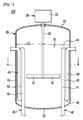
図1は、本発明の第1の実施形態に係る回分式反応器の概略図であり、図2は、図1のI−I線を基準に切開した回分式反応器の概略断面図である。 FIG. 1 is a schematic view of a batch reactor according to a first embodiment of the present invention, and FIG. 2 is a schematic cross-sectional view of the batch reactor cut along line II in FIG. .
図1及び図2を参照すると、第1の実施形態の回分式反応器100は、反応物10を受容するための反応器本体20と、反応器本体20の内部に設置されている攪拌翼31であって、反応物10を回転させるための攪拌翼31と、攪拌翼31の回転軸32に結合しているモータ33であって、攪拌翼31を回転させるためのモータ33と、反応器本体20の内壁と攪拌翼31の間に位置する複数のバッフル40とを含んでいる。
Referring to FIGS. 1 and 2, a
回分式反応器100は、例えば、高分子重合のための重合反応器であってもよい。反応器本体20は、円筒形の側壁21と底部22及び蓋部23から構成され得る。図示は省略したが、反応器本体20は、二重壁構造で形成されてており、二重壁内部との熱交換のために流体を循環させることができる。言い換えれば、反応器本体20に熱交換ジャケットが設置されている。
The
攪拌翼31、回転軸32、及びモータ33が攪拌装置30を構成する。回転軸32は、反応器本体20の中央でモータ33と結合する。攪拌翼31は、反応器本体20の内部で回転軸32に結合しており、攪拌翼31の長さ方向は反応器本体20の径方向と一致している。
The stirring
1セットの攪拌翼31が回転軸32の下側端部に設置されているか、又は、複数のセットの攪拌翼が回転軸32の長さ方向に沿って互いから離隔して設置されている。1セットの攪拌翼31は、少なくとも2つの攪拌翼31から構成されている。図1及び図2では回転軸32の下側端部に2つの攪拌翼31が設置されている構成を例に上げて示したが、攪拌翼31の設置位置と個数は示した例に限定されない。
One set of stirring
攪拌翼31の攪拌性能は、回分式反応器100の反応性能に影響を与える。攪拌翼31は、パドル(paddle)タイプ、プロペラ(propeller)タイプ、及びタービン(turbine)タイプなどがあり、図1及び図2ではパドルタイプの攪拌翼31を例に上げて示したが、攪拌翼31は示した例に限定されない。
The stirring performance of the stirring
バッフル40は、攪拌翼31の回転に応じた反応物10の周方向流れを上下方向流れに変えて反応物10の混合を良好にする機能を果たす。また、バッフル40は、その内部へ熱交換のための流体が流れる配管から構成されるため、反応物10との熱交換を通じて反応物10の温度を一定に維持させる温度制御(制熱)機能を果たす。
The
熱交換のための流体は、低温の場合、ほぼ4℃〜35℃の温度を有することができ、 高温の場合、ほぼ50℃〜200℃の温度を有することができる。 The fluid for heat exchange can have a temperature of approximately 4 ° C. to 35 ° C. when the temperature is low, and can have a temperature of approximately 50 ° C. to 200 ° C. when the temperature is high.
複数のバッフル40は、反応器本体20の周方向に沿って互いから離隔して配置されている。言い換えれば、複数のバッフル40は、攪拌翼31から一定距離で離隔して反応器本体20の周方向に沿って設置されており、好ましくは周方向に沿って等間隔に設置されている。
The plurality of
バッフル40それぞれは、回転軸32と平行な複数の配管41、42、43が蛇行パターンで一体に連結した構成から成る。具体的に、バッフル40は、第1の配管41と、U字状の第1の連結部44を介して第1の配管41に結合した第2の配管42と、U字状の第2の連結部45を介して第2の配管42に結合した第3の配管43とを含むことができる。第1の配管41は、反応器本体20の底部22を貫通しており、第3の配管43は、反応器本体20の側壁21を貫通している場合がある。第1の連結部44と第2の連結部45は、U字状の構造に限定されない。
Each of the
第1の実施形態では、バッフル40それぞれは、第1〜第3の配管41、42、43を含んでおり、第1〜第3の配管41、42、43は、反応器本体20の径方向及び周方向に沿って互いに隣り合うように配置されている。言い換えれば、いずれか1つの配管に対して他の1つの配管の少なくとも一部が反応器本体20の径方向に沿って対向しており、他の配管の少なくとも一部が反応器本体20の周方向に沿って対向している。
In the first embodiment, each
例えば、第1〜第3の配管41、42、43は、互いから一定距離で離隔して三角パターンで配列されてもよい。このような配管構成は、反応器本体20の径方向に沿ってバッフル40が占める領域の大きさを縮小させて攪拌翼31の拡張を可能にする。攪拌翼31を拡張することによって、反応物10の攪拌性能及び反応性能が向上する。
For example, the 1st-
この時、第1〜第3の配管41、42、43のうち2つの配管は、反応器本体20の径方向に沿って配列されてもよい。この場合、攪拌翼31によって回転される反応物10とバッフル40の接触性を良好にしてバッフル40の制熱性能を高めることができる。
At this time, two of the first to
図3は、比較例による回分式反応器を示す概略断面図である。 FIG. 3 is a schematic cross-sectional view showing a batch reactor according to a comparative example.
図3を参照すると、比較例の回分式反応器101で複数のバッフル401それぞれが、反応器本体201の径方向に沿って一列に配置された第1〜第3の配管411、421、431から構成される。
Referring to FIG. 3, each of the plurality of
図2及び図3を参照すると、第1の実施形態の第1〜第3の配管41、42、43と比較例の第1〜第3の配管411、421、431が同一の長さの同一の直径を有する場合、第1の実施形態のバッフル40と比較例のバッフル401は、同一の電熱面積を有しているので、ほとんど同等な制熱性能を発揮する。
2 and 3, the first to
しかしながら、比較例の場合、バッフル401が反応器本体201の径方向に沿って大きい領域を占めるので、攪拌翼311がバッフル401と衝突しないようにするためには、攪拌翼311の大きさを小さくせざるを得ない。言い換えれば、バッフル401に起因して、攪拌翼311の大きさの拡大が著しく制限される。
However, in the case of the comparative example, since the
反面、第1の実施形態では、第1〜第3の配管41、42、43が三角パターンで稠密に配列されているので、バッフル40は、反応器本体20の径方向に沿って大きい領域を占めない。従って、第1の実施形態に係る回分式反応器100では、攪拌翼31の大きさを拡張させることができ、反応物10の乱流増加及び混合性能を改善して反応物10の製造品質を向上させることができる。
On the other hand, in the first embodiment, since the first to
図4は、本発明の第2の実施形態による回分式反応器の概略断面図である。 FIG. 4 is a schematic cross-sectional view of a batch reactor according to the second embodiment of the present invention.
図4を参照すると、第2の実施形態による回分式反応器200は、バッフル50が5つの配管51、52、53、54、55から構成されたことを除き、前述した第1の実施形態と類似する構造から成る。第1の実施形態と同一の部材については同一の図面符号を使い、以下では第1の実施形態と同一の構成について主に説明する。
Referring to FIG. 4, the
複数のバッフル50は、攪拌翼31から一定距離で離隔して反応器本体20の周方向に沿って等間隔に設置されており、バッフル50それぞれは、回転軸32と平行な第1〜第5の配管51、52、53、54、55が蛇行パターンで一体に連結した構成から成る。
The plurality of
第1〜第5の配管51、52、53、54、55は、図示しないU字状の連結部を介して一体に結合されており、1つのバッフル50を構成している。第1〜第5の配管51、52、53、54、55のうちいずれか1つの配管が反応器本体20の底部22を貫通しており、他の1つの配管が反応器本体20の側壁21を貫通している場合がある。
The first to
第2の実施形態では、バッフル50それぞれは、第1〜第5の配管51、52、53、54、55を含んでおり、第1〜第5の配管51、52、53、54、55は、反応器本体20の径方向及び周方向に沿って互いに隣り合うように配置されている。言い換えれば、いずれか1つの配管に対して他の1つの配管の少なくとも一部が反応器本体20の径方向に沿って対向しており、他の配管の少なくとも一部が反応器本体20の周方向に沿って対向している。
In the second embodiment, each
例えば、第1〜第5の配管51、52、53、54、55は、2つの列をなしてジグザグパターンで配列されてもよい。図4を基準に最右側に位置するバッフル50で第1〜第5の配管51、52、53、54、55の中心を連結する仮想のジグザグ連結線を点線で表示した。
For example, the first to
この時、2つの列のうち少なくとも1つの列は、反応器本体20の径方向に沿って一列に配列され得る。この場合、攪拌翼31によって反応器本体20の周方向に沿って流される反応物10とバッフル50の接触面積を増やしてバッフル50の制熱性能を向上させることができる。
At this time, at least one of the two rows may be arranged in a row along the radial direction of the
図4は、第1〜第3の配管51、52、53が反応器本体20の径方向に沿って1つの列をなし、第4及び第5の配管54、55が隣り合う他の列を成して配列された構成を例に上げて示す。
In FIG. 4, the first to
前述した第2の実施形態では、図3に示した比較例に比べて攪拌翼31の幅は同一に維持しながらバッフル50を構成する配管の数を増やしてバッフル50の電熱面積を60%以上拡大させることができる。従って、第2の実施形態の回分式反応器200は、比較例と同等水準の攪拌能力を確保しながら反応物10の制熱性能を効果的に向上させることができる。
In the second embodiment described above, the electric heating area of the
以上で、本発明の好ましい実施形態について説明したが、本発明はこれに限定されるのではなく、特許請求の範囲と発明の詳細な説明及び添付した図面の範囲内で多様に変形して実施することが可能であり、これも本発明の範囲に属するのは当然である。 The preferred embodiments of the present invention have been described above. However, the present invention is not limited thereto, and various modifications may be made within the scope of the claims, the detailed description of the invention, and the attached drawings. Of course, this is also within the scope of the present invention.
本発明の一実施形態によれば、攪拌翼の大きさを拡張させて反応物の乱流増加及び混合性能を改善することができ、従来と同等水準の攪拌能力を維持しながらバッフルの電熱面積を拡大させて反応物の制熱性能を向上させることができる。 According to an embodiment of the present invention, the size of the stirring blade can be expanded to improve the turbulent flow of the reactants and improve the mixing performance. The thermal insulation performance of the reactant can be improved.
20 反応器本体
31 攪拌翼
32 回転軸
33 モータ
40 バッフル
50 バッフル
100 回分式反応器
200 回分式反応器
401 バッフル
20
Claims (8)
前記反応器本体の内部に設置されている攪拌翼であって、反応物を攪拌するための前記攪拌翼と、
前記攪拌翼の回転軸に結合しているモータであって、前記攪拌翼を回転させる前記モータと、
前記反応器本体の内壁と前記攪拌翼の間に位置しており、前記反応器本体の周方向に沿って互いから離隔して設置されている複数のバッフルと、
を含んでいる回分式反応器において、
前記複数のバッフルそれぞれが、前記反応器本体の径方向及び周方向に沿って互いに隣り合うように配置された複数の配管を含んでいることを特徴とする回分式反応器。 A reactor body for receiving the reactants;
A stirring blade installed inside the reactor body, the stirring blade for stirring the reaction product;
A motor coupled to a rotating shaft of the stirring blade, the motor rotating the stirring blade;
A plurality of baffles that are located between the inner wall of the reactor body and the stirring blade and are spaced apart from each other along the circumferential direction of the reactor body;
In a batch reactor containing
Each of the plurality of baffles includes a plurality of pipes arranged so as to be adjacent to each other along a radial direction and a circumferential direction of the reactor main body.
Applications Claiming Priority (3)
| Application Number | Priority Date | Filing Date | Title |
|---|---|---|---|
| KR1020140000241A KR101572126B1 (en) | 2014-01-02 | 2014-01-02 | Batch reactor with baffle |
| KR10-2014-0000241 | 2014-01-02 | ||
| PCT/KR2014/012530 WO2015102273A1 (en) | 2014-01-02 | 2014-12-18 | Batch reactor with baffle |
Publications (1)
| Publication Number | Publication Date |
|---|---|
| JP2017507015A true JP2017507015A (en) | 2017-03-16 |
Family
ID=53493576
Family Applications (1)
| Application Number | Title | Priority Date | Filing Date |
|---|---|---|---|
| JP2016544376A Pending JP2017507015A (en) | 2014-01-02 | 2014-12-18 | Batch reactor with baffle |
Country Status (6)
| Country | Link |
|---|---|
| US (1) | US20160332132A1 (en) |
| EP (1) | EP3090800A4 (en) |
| JP (1) | JP2017507015A (en) |
| KR (1) | KR101572126B1 (en) |
| CN (1) | CN105873675A (en) |
| WO (1) | WO2015102273A1 (en) |
Families Citing this family (9)
| Publication number | Priority date | Publication date | Assignee | Title |
|---|---|---|---|---|
| CN106622087A (en) * | 2017-02-03 | 2017-05-10 | 天津创赢东华科技有限公司 | Novel PU (Polyurethane) resin reaction kettle |
| GB201809679D0 (en) | 2018-06-13 | 2018-08-01 | Process Tech Strategic Consultancy Limited | Batch processing apparatus |
| KR102395229B1 (en) * | 2018-09-11 | 2022-05-04 | 한화솔루션 주식회사 | Batch reactor with baffle |
| CN109569365A (en) * | 2018-11-23 | 2019-04-05 | 黎庆佳 | A kind of food liquid detection pretreatment unit with agitating function |
| KR102267818B1 (en) * | 2018-12-12 | 2021-06-21 | 주식회사 포스코 | Overflow continuous reactor |
| CN110105167B (en) * | 2019-03-27 | 2022-03-04 | 东营市科维生物技术有限公司 | Method and device for continuously producing polyols for polyesters |
| KR102265495B1 (en) | 2019-11-01 | 2021-06-15 | 주식회사 포스코 | Carbonation reactor for improving membrane stability |
| KR20210059512A (en) * | 2019-11-15 | 2021-05-25 | 한화솔루션 주식회사 | Polymerization reactor |
| KR20240023889A (en) | 2022-08-16 | 2024-02-23 | 주식회사 엘지화학 | Polymerization reactor with heat exchange coil |
Citations (5)
| Publication number | Priority date | Publication date | Assignee | Title |
|---|---|---|---|---|
| JPS5023773U (en) * | 1973-03-28 | 1975-03-17 | ||
| JPS62186783A (en) * | 1986-02-05 | 1987-08-15 | フイリツプス ピトロ−リアム カンパニ− | Fermentation apparatus |
| JPH01193590A (en) * | 1987-11-17 | 1989-08-03 | Phillips Petroleum Co | Device and method of exchanging heat |
| JP2005002194A (en) * | 2003-06-11 | 2005-01-06 | Chisso Corp | Reactor, apparatus for olefin polymerization including it and manufacturing process for olefin polymer using the polymerization apparatus |
| WO2005005040A1 (en) * | 2003-07-14 | 2005-01-20 | Dsm Ip Assets B.V. | Heat exchanger and reactor comprising said type of heat exchanger |
Family Cites Families (4)
| Publication number | Priority date | Publication date | Assignee | Title |
|---|---|---|---|---|
| JPH06142479A (en) * | 1992-11-10 | 1994-05-24 | Shinko Pantec Co Ltd | Stirrer and agitation method using it |
| JPH08311186A (en) * | 1995-05-16 | 1996-11-26 | Mitsui Toatsu Chem Inc | Production of polyhydroxycarboxylic acid |
| JPH08311187A (en) * | 1995-05-17 | 1996-11-26 | Mitsui Toatsu Chem Inc | Production of polyhydroxycarboxylic acid |
| JPH093001A (en) * | 1995-06-19 | 1997-01-07 | Nkk Corp | Production of naphthalenedicarboxylic acid and reactor |
-
2014
- 2014-01-02 KR KR1020140000241A patent/KR101572126B1/en active IP Right Grant
- 2014-12-18 WO PCT/KR2014/012530 patent/WO2015102273A1/en active Application Filing
- 2014-12-18 US US15/108,881 patent/US20160332132A1/en not_active Abandoned
- 2014-12-18 EP EP14877054.8A patent/EP3090800A4/en not_active Withdrawn
- 2014-12-18 CN CN201480072202.5A patent/CN105873675A/en active Pending
- 2014-12-18 JP JP2016544376A patent/JP2017507015A/en active Pending
Patent Citations (5)
| Publication number | Priority date | Publication date | Assignee | Title |
|---|---|---|---|---|
| JPS5023773U (en) * | 1973-03-28 | 1975-03-17 | ||
| JPS62186783A (en) * | 1986-02-05 | 1987-08-15 | フイリツプス ピトロ−リアム カンパニ− | Fermentation apparatus |
| JPH01193590A (en) * | 1987-11-17 | 1989-08-03 | Phillips Petroleum Co | Device and method of exchanging heat |
| JP2005002194A (en) * | 2003-06-11 | 2005-01-06 | Chisso Corp | Reactor, apparatus for olefin polymerization including it and manufacturing process for olefin polymer using the polymerization apparatus |
| WO2005005040A1 (en) * | 2003-07-14 | 2005-01-20 | Dsm Ip Assets B.V. | Heat exchanger and reactor comprising said type of heat exchanger |
Also Published As
| Publication number | Publication date |
|---|---|
| US20160332132A1 (en) | 2016-11-17 |
| WO2015102273A1 (en) | 2015-07-09 |
| EP3090800A1 (en) | 2016-11-09 |
| KR101572126B1 (en) | 2015-11-26 |
| EP3090800A4 (en) | 2017-08-02 |
| KR20150080774A (en) | 2015-07-10 |
| CN105873675A (en) | 2016-08-17 |
Similar Documents
| Publication | Publication Date | Title |
|---|---|---|
| JP2017507015A (en) | Batch reactor with baffle | |
| ES2677706T3 (en) | Heat exchanger for condensing boiler | |
| RU2689890C2 (en) | Condensing heat exchanger with two coils for heating water and/or producing hot water for household needs | |
| BRPI0911382B1 (en) | process for exchanging heat with a mixed phase fluid | |
| EP3273174B1 (en) | Liquid heating device | |
| JP2015518149A5 (en) | ||
| CN110726325A (en) | Fin for tube-fin heat exchanger, tube-fin heat exchanger and air conditioner | |
| JP4451504B2 (en) | Reactor heat exchange system | |
| JP2010038429A (en) | Heat exchanger | |
| EP3730888A1 (en) | Heat exchanger | |
| JP2022536053A (en) | heat exchanger with spiral baffle | |
| JP2014147925A (en) | Multitubular reactor | |
| JP2006507377A (en) | Method and apparatus for continuous production of polyester | |
| TW202124038A (en) | Polymerization reactor | |
| CN209978658U (en) | Shell and tube heat exchanger and air conditioning unit | |
| CN109899987B (en) | Heat exchanger | |
| CN104006678A (en) | Cooling tower with agitating vanes | |
| RU2018106653A (en) | Heat exchanger and method for distributing a liquid phase in a heat exchanger | |
| US1764535A (en) | Apparatus for exchange of heat | |
| EP3358271B1 (en) | Water heater and a pipe coil for a heat exchanger, in particular an exchanger intended for that specific water heater | |
| CN103733011B (en) | Gas gas heat exchanger | |
| CN112654424B (en) | Batch reactor with baffles | |
| JP2009250450A (en) | Pyrolytic pipe | |
| KR20240001691A (en) | Cooling baffle and reactor including the same | |
| CN105555398A (en) | Melt condensation polymerization reactor |
Legal Events
| Date | Code | Title | Description |
|---|---|---|---|
| A977 | Report on retrieval |
Free format text: JAPANESE INTERMEDIATE CODE: A971007 Effective date: 20170713 |
|
| A131 | Notification of reasons for refusal |
Free format text: JAPANESE INTERMEDIATE CODE: A131 Effective date: 20170724 |
|
| A601 | Written request for extension of time |
Free format text: JAPANESE INTERMEDIATE CODE: A601 Effective date: 20171020 |
|
| A521 | Request for written amendment filed |
Free format text: JAPANESE INTERMEDIATE CODE: A523 Effective date: 20171127 |
|
| A02 | Decision of refusal |
Free format text: JAPANESE INTERMEDIATE CODE: A02 Effective date: 20180312 |