JP2017506305A - Wave energy converter using orbital motion of weight carriage - Google Patents
Wave energy converter using orbital motion of weight carriage Download PDFInfo
- Publication number
- JP2017506305A JP2017506305A JP2016552311A JP2016552311A JP2017506305A JP 2017506305 A JP2017506305 A JP 2017506305A JP 2016552311 A JP2016552311 A JP 2016552311A JP 2016552311 A JP2016552311 A JP 2016552311A JP 2017506305 A JP2017506305 A JP 2017506305A
- Authority
- JP
- Japan
- Prior art keywords
- wave energy
- energy conversion
- conversion module
- carriage
- generator
- Prior art date
- Legal status (The legal status is an assumption and is not a legal conclusion. Google has not performed a legal analysis and makes no representation as to the accuracy of the status listed.)
- Granted
Links
- 230000033001 locomotion Effects 0.000 title claims abstract description 83
- 238000006243 chemical reaction Methods 0.000 claims abstract description 76
- 238000007667 floating Methods 0.000 claims abstract description 13
- 239000000725 suspension Substances 0.000 claims description 20
- 230000005484 gravity Effects 0.000 claims description 14
- 238000012423 maintenance Methods 0.000 claims description 10
- 230000005540 biological transmission Effects 0.000 claims description 6
- 238000004873 anchoring Methods 0.000 claims description 4
- 239000012530 fluid Substances 0.000 claims description 4
- 238000000926 separation method Methods 0.000 claims description 4
- 239000011295 pitch Substances 0.000 description 21
- 230000000694 effects Effects 0.000 description 15
- 238000005381 potential energy Methods 0.000 description 14
- 238000000605 extraction Methods 0.000 description 12
- 239000000463 material Substances 0.000 description 12
- 230000009471 action Effects 0.000 description 10
- 230000008901 benefit Effects 0.000 description 10
- 230000009467 reduction Effects 0.000 description 10
- XLYOFNOQVPJJNP-UHFFFAOYSA-N water Substances O XLYOFNOQVPJJNP-UHFFFAOYSA-N 0.000 description 10
- 238000000034 method Methods 0.000 description 9
- 230000000295 complement effect Effects 0.000 description 8
- 238000004519 manufacturing process Methods 0.000 description 6
- 238000009826 distribution Methods 0.000 description 5
- 238000013459 approach Methods 0.000 description 4
- 230000002093 peripheral effect Effects 0.000 description 4
- 238000005086 pumping Methods 0.000 description 4
- 238000005096 rolling process Methods 0.000 description 4
- 238000012546 transfer Methods 0.000 description 4
- 230000001276 controlling effect Effects 0.000 description 3
- 230000007423 decrease Effects 0.000 description 3
- 229910001208 Crucible steel Inorganic materials 0.000 description 2
- PEDCQBHIVMGVHV-UHFFFAOYSA-N Glycerine Chemical compound OCC(O)CO PEDCQBHIVMGVHV-UHFFFAOYSA-N 0.000 description 2
- 238000005452 bending Methods 0.000 description 2
- 230000002457 bidirectional effect Effects 0.000 description 2
- 230000008859 change Effects 0.000 description 2
- 239000002131 composite material Substances 0.000 description 2
- 230000002596 correlated effect Effects 0.000 description 2
- 238000011161 development Methods 0.000 description 2
- 238000006073 displacement reaction Methods 0.000 description 2
- 230000005284 excitation Effects 0.000 description 2
- 230000010354 integration Effects 0.000 description 2
- 239000000203 mixture Substances 0.000 description 2
- 230000006855 networking Effects 0.000 description 2
- 230000000737 periodic effect Effects 0.000 description 2
- 230000002265 prevention Effects 0.000 description 2
- 230000002441 reversible effect Effects 0.000 description 2
- 238000007493 shaping process Methods 0.000 description 2
- 239000007787 solid Substances 0.000 description 2
- 230000006641 stabilisation Effects 0.000 description 2
- 238000011105 stabilization Methods 0.000 description 2
- 238000011144 upstream manufacturing Methods 0.000 description 2
- 239000002699 waste material Substances 0.000 description 2
- 230000000875 corresponding effect Effects 0.000 description 1
Images


Classifications
-
- F—MECHANICAL ENGINEERING; LIGHTING; HEATING; WEAPONS; BLASTING
- F03—MACHINES OR ENGINES FOR LIQUIDS; WIND, SPRING, OR WEIGHT MOTORS; PRODUCING MECHANICAL POWER OR A REACTIVE PROPULSIVE THRUST, NOT OTHERWISE PROVIDED FOR
- F03B—MACHINES OR ENGINES FOR LIQUIDS
- F03B13/00—Adaptations of machines or engines for special use; Combinations of machines or engines with driving or driven apparatus; Power stations or aggregates
- F03B13/12—Adaptations of machines or engines for special use; Combinations of machines or engines with driving or driven apparatus; Power stations or aggregates characterised by using wave or tide energy
- F03B13/14—Adaptations of machines or engines for special use; Combinations of machines or engines with driving or driven apparatus; Power stations or aggregates characterised by using wave or tide energy using wave energy
- F03B13/16—Adaptations of machines or engines for special use; Combinations of machines or engines with driving or driven apparatus; Power stations or aggregates characterised by using wave or tide energy using wave energy using the relative movement between a wave-operated member, i.e. a "wom" and another member, i.e. a reaction member or "rem"
- F03B13/20—Adaptations of machines or engines for special use; Combinations of machines or engines with driving or driven apparatus; Power stations or aggregates characterised by using wave or tide energy using wave energy using the relative movement between a wave-operated member, i.e. a "wom" and another member, i.e. a reaction member or "rem" wherein both members, i.e. wom and rem are movable relative to the sea bed or shore
-
- F—MECHANICAL ENGINEERING; LIGHTING; HEATING; WEAPONS; BLASTING
- F03—MACHINES OR ENGINES FOR LIQUIDS; WIND, SPRING, OR WEIGHT MOTORS; PRODUCING MECHANICAL POWER OR A REACTIVE PROPULSIVE THRUST, NOT OTHERWISE PROVIDED FOR
- F03B—MACHINES OR ENGINES FOR LIQUIDS
- F03B13/00—Adaptations of machines or engines for special use; Combinations of machines or engines with driving or driven apparatus; Power stations or aggregates
- F03B13/12—Adaptations of machines or engines for special use; Combinations of machines or engines with driving or driven apparatus; Power stations or aggregates characterised by using wave or tide energy
- F03B13/14—Adaptations of machines or engines for special use; Combinations of machines or engines with driving or driven apparatus; Power stations or aggregates characterised by using wave or tide energy using wave energy
- F03B13/22—Adaptations of machines or engines for special use; Combinations of machines or engines with driving or driven apparatus; Power stations or aggregates characterised by using wave or tide energy using wave energy using the flow of water resulting from wave movements to drive a motor or turbine
-
- B—PERFORMING OPERATIONS; TRANSPORTING
- B63—SHIPS OR OTHER WATERBORNE VESSELS; RELATED EQUIPMENT
- B63B—SHIPS OR OTHER WATERBORNE VESSELS; EQUIPMENT FOR SHIPPING
- B63B35/00—Vessels or similar floating structures specially adapted for specific purposes and not otherwise provided for
- B63B35/44—Floating buildings, stores, drilling platforms, or workshops, e.g. carrying water-oil separating devices
- B63B2035/4433—Floating structures carrying electric power plants
- B63B2035/4466—Floating structures carrying electric power plants for converting water energy into electric energy, e.g. from tidal flows, waves or currents
-
- F—MECHANICAL ENGINEERING; LIGHTING; HEATING; WEAPONS; BLASTING
- F05—INDEXING SCHEMES RELATING TO ENGINES OR PUMPS IN VARIOUS SUBCLASSES OF CLASSES F01-F04
- F05B—INDEXING SCHEME RELATING TO WIND, SPRING, WEIGHT, INERTIA OR LIKE MOTORS, TO MACHINES OR ENGINES FOR LIQUIDS COVERED BY SUBCLASSES F03B, F03D AND F03G
- F05B2250/00—Geometry
- F05B2250/40—Movement of component
- F05B2250/44—Movement of component one element moving inside another one, e.g. wave-operated member (wom) moving inside another member (rem)
-
- Y—GENERAL TAGGING OF NEW TECHNOLOGICAL DEVELOPMENTS; GENERAL TAGGING OF CROSS-SECTIONAL TECHNOLOGIES SPANNING OVER SEVERAL SECTIONS OF THE IPC; TECHNICAL SUBJECTS COVERED BY FORMER USPC CROSS-REFERENCE ART COLLECTIONS [XRACs] AND DIGESTS
- Y02—TECHNOLOGIES OR APPLICATIONS FOR MITIGATION OR ADAPTATION AGAINST CLIMATE CHANGE
- Y02E—REDUCTION OF GREENHOUSE GAS [GHG] EMISSIONS, RELATED TO ENERGY GENERATION, TRANSMISSION OR DISTRIBUTION
- Y02E10/00—Energy generation through renewable energy sources
- Y02E10/30—Energy from the sea, e.g. using wave energy or salinity gradient
Abstract
本発明は、波力エネルギー変換モジュールに関するものであって、船体(1)を備えた浮遊物体として構成され、船体の縦揺れ運動が偏心質量へと伝達されて、偏心質量が中心軸線(3)まわりに回転し得るものとされ、このような波力エネルギー変換モジュールにおいて、縦揺れ運動が、船体(1)の形状によって励起され、および、動的に調節可能とされた可動バラストによって励起され、偏心質量が、摩擦および負荷を制限するローラによって一組をなす複数の円形レール(6)に沿った軌道を描く自律的なキャリッジ(5)の態様とされ、キャリッジ(5)上に取り付けられた発電機(8)が、ギヤラック(9)に対して噛合している。The present invention relates to a wave energy conversion module, which is configured as a floating object provided with a hull (1), wherein the pitching motion of the hull is transmitted to the eccentric mass, and the eccentric mass is the central axis (3). In such a wave energy conversion module, the pitching motion is excited by the shape of the hull (1) and by a movable ballast that can be adjusted dynamically, in such a wave energy conversion module, The eccentric mass is in the form of an autonomous carriage (5) that draws a track along a plurality of circular rails (6) paired by rollers that limit friction and load and is mounted on the carriage (5) The generator (8) meshes with the gear rack (9).
Description
現在まで、様々な波力エネルギーシステムが考案されて開発されてきた。しかしながら、期待される性能に見合った実用的応用には至っていない。 To date, various wave energy systems have been devised and developed. However, it has not reached a practical application commensurate with the expected performance.
既存の発明の様々な分類どうしを比較することにより、機能的なおよび経済的な開発可能性の観点から最も有用な特徴点を識別することができ、それぞれの限界を分析することができる。これにより、波力エネルギーを電力へと効率的に変換するのに必要な実施や操作に関する実用的条件を満たす新たなデバイスを開発することができる。 By comparing various classifications of existing inventions, the most useful feature points can be identified in terms of functional and economic development possibilities, and their respective limits can be analyzed. Thereby, it is possible to develop a new device that satisfies a practical condition regarding implementation and operation necessary for efficiently converting wave energy into electric power.
よって、単一の浮遊ボディ内にデバイスの全体を包含させるという原理によって、海底基礎の問題点を回避することができ、さらに、外部構成部材を有していないことによって、システムの頑丈さが保証されるとともに海洋環境への適合が保証されることが、見出された。 Thus, the principle of enclosing the entire device in a single floating body avoids the problems of submarine foundations, and the absence of external components ensures the robustness of the system And found to be compatible with the marine environment.
その他にも、油圧伝達構成部材を設けることなく、直接的な電気機械的変換というある種の態様とすることにより、単純な実施態様および単純な操作によって、固体の移動を利用することができる。 In addition, the solid movement can be utilized by a simple embodiment and a simple operation by providing a certain type of direct electromechanical conversion without providing a hydraulic transmission component.
このような変換方法を全体的にあるいは部分的に使用した特許文献について、以下のものに言及することができる。
−特許文献1:波と一緒に縦揺れする浮遊物体であるとともに、その縦揺れを偏心ドライブへと伝達して、水平方向平面内において振り子式に振動させる。
−特許文献2,3:1つまたは複数の偏心物体であるとともに、波の振動の結果として、水平方向平面内において、全回転を行い、逆回り回転を行わない。
The following can be mentioned about the patent document which used such a conversion method in whole or in part.
Patent Document 1: A floating object that pitches with a wave, and transmits the pitch to an eccentric drive to vibrate in a pendulum manner in a horizontal plane.
Patent Documents 2 and 3: One or more eccentric objects, and as a result of wave vibration, perform full rotation and no reverse rotation in the horizontal plane.
操作という観点から、上記のタイプのシステムにおける限界には、主として、以下のようなものがある。
−デバイスを移動状態にセットするに際し、大部分の波の態様を利用することが困難であること。
−発電機のための定常的操作レジームを維持するに際し、波の周波数に対してデバイスを同期させることが困難であること。
−様々な構成部材どうしの間における摩擦のために、損失が発生すること。
これらの限界の合計のために、生産ロジックにおける全体的収率が低下してしまうこととなる。
From an operational point of view, the limitations in the above type of system are mainly as follows.
-It is difficult to use most wave modes when setting the device in the moving state.
-It is difficult to synchronize the device to the wave frequency in maintaining a steady operating regime for the generator.
-Loss occurs due to friction between the various components.
The sum of these limits will reduce the overall yield in production logic.
本明細書においては、本発明は、一組をなす複数の解決手法を規定するものであり、とりわけ、波の周波数に対しての電力抽出デバイスの同期を最適化するための様々なフレキシブルさと、小さな摩擦での構成部材の使用と、慣習的なエンジニアリング技術および製造技術の使用と、安価な材料やリサイクル材料の使用と、最小で容易なメンテナンスと、を提供する。 In the present specification, the present invention defines a set of solutions, in particular various flexibility to optimize the synchronization of the power extraction device to the wave frequency, It provides the use of components with low friction, the use of conventional engineering and manufacturing techniques, the use of inexpensive materials and recycled materials, and minimal and easy maintenance.
本発明の主題をなす波力エネルギー変換器は、実質的に浮遊型の閉塞ボディから構成され、このボディは、波の振動から電力を生成するための電気的機械的変換デバイスを全体的に収容している。 The wave energy converter that forms the subject of the present invention consists essentially of a floating occluded body, which generally contains an electromechanical conversion device for generating electrical power from wave vibrations. doing.
船体は、あるいはボディの浸漬部分は、係留される、すなわち、モータ付きデバイスによって所定位置に保持される。一組をなす複数のフィンが設けられ、これにより、波頭に対向した配向性が一定に維持される。船体は、波の上下動に応じて、モジュールの縦揺れ運動に適した格別の形状を有している。説明の簡略化のために、船体のうちの、入力波に対して最初に接触する部分は、本明細書では、モジュールの前方部分と称され、すなわち、船首と称されることに、また、反対側の部分は、モジュールの後方部分と称され、すなわち、船尾と称されることに、注意されたい。 The hull or the immersed part of the body is moored, i.e. held in place by a motorized device. A plurality of fins forming a set is provided, whereby the orientation facing the wave front is kept constant. The hull has a special shape suitable for the pitching motion of the module according to the vertical movement of the wave. For simplicity of explanation, the portion of the hull that first contacts the input wave is referred to herein as the front portion of the module, ie, referred to as the bow, and Note that the opposite portion is referred to as the rear portion of the module, ie, the stern.
ボディの内部においては、偏心質量は、錘キャリッジの態様とされ、一組をなす複数の円形レールに沿って移動することができる。この種の構成により、中央キャリングシャフトを不要とすることができる。これにより、中央の回転軸線上における偏心質量の意義深い曲げモーメントに起因する摩擦を回避することができる。 Inside the body, the eccentric mass is in the form of a weight carriage and can move along a set of circular rails. This type of configuration can eliminate the need for a central carrying shaft. Thereby, the friction resulting from the significant bending moment of the eccentric mass on the central rotation axis can be avoided.
ボディの縦揺れ運動は、レールがなす平面を傾斜させ、これにより、キャリッジの重量の効果のために、キャリッジを移動させてしまう。例えば振り子運動の際に起こるような、軌道上のブレークポイントすなわち反転ポイントの存在に特有の電気的機械的問題点に打ち勝ち得るよう、本発明は、中央軸線まわりにおけるキャリッジの完全な軌道すなわち妨害されていない軌道の利点を有することができる。 The pitching motion of the body tilts the plane formed by the rails, thereby moving the carriage due to the effect of the weight of the carriage. In order to overcome the electromechanical problems unique to the presence of breakpoints or reversal points on the trajectory, such as occur during pendulum movement, the present invention provides a complete trajectory or obstruction of the carriage around the central axis. Not have the advantage of a trajectory.
運動時に偏心質量が獲得する運動エネルギーは、軌道がなす平面を傾斜させることによって波が偏心質量を持ち上げた際の位置エネルギーに依存する。 The kinetic energy acquired by the eccentric mass during movement depends on the potential energy when the wave lifts the eccentric mass by tilting the plane formed by the trajectory.
軌道の傾斜の大きさが小さいことのために、摩擦が、ある種の波の高さ以下の場合に乗り越えられなくなり得る主要な制限である。この点に関し、本発明は、キャリッジが移動する際の摩擦損失を低減することを目的とした一組をなす複数の構成を提供する。 Because of the small magnitude of the trajectory slope, friction is a major limitation that can be overcome when below certain wave heights. In this regard, the present invention provides a plurality of configurations for the purpose of reducing friction loss when the carriage moves.
集積された運動エネルギーは、キャリッジに対して一体化された発電機によって変換される。発電機シャフトは、レールと同軸的な一組をなす複数のギヤラックに対して噛合した1つまたは2つのコグホイールによって、回転駆動される。スライドコンタクトが、発電機を、電気的整流器に対して接続する。これにより、地上の分配ステーションに対してのモジュールの電気的接続は、海洋環境を通しての交流送電に起因するライン損失を回避する。 The accumulated kinetic energy is converted by a generator integrated with the carriage. The generator shaft is rotationally driven by one or two cog wheels that mesh with a plurality of gear racks that are coaxial with the rail. A slide contact connects the generator to the electrical rectifier. Thereby, the electrical connection of the module to the distribution station on the ground avoids line losses due to AC power transmission through the marine environment.
可動バラストも、また、波の上下動によって、駆動される。可動バラストは、入力波の向きにおけるモジュールの傾斜を増大させる。これにより、キャリッジの落下高さを増大させる。 The movable ballast is also driven by the up and down movement of the waves. The movable ballast increases the slope of the module in the direction of the input wave. This increases the fall height of the carriage.
この傾斜位置に起因する電力抽出サイクルは、概略的には、以下の4つのフェーズに分解することができる。
−入力波の効果によって傾斜が増大するフェーズにおいて、キャリッジの軌道を、船首の近傍に位置させ、これにより、キャリッジに、重力に基づく位置エネルギーを獲得させるフェーズ。
−モジュールが最大傾斜に到達した後に、キャリッジを下向きに加速させながら、位置エネルギーを運動エネルギーへと変換するフェーズ。このフェーズは、短いものである。なぜなら、最大傾斜が一時的であるからである。
−モジュールが波頭を乗り越えたことのために傾斜が減少するフェーズにおいて、キャリッジの軌道を、船尾の近傍に位置させ、これにより、キャリッジに、重力に基づく位置エネルギーを再び獲得させるフェーズ。
−波が船尾を持ち上げることのために、モジュールが最大傾斜に到達した後に、キャリッジを加速させながら、位置エネルギーを再び運動エネルギーへと変換するフェーズ。
The power extraction cycle resulting from this tilt position can be roughly broken down into the following four phases.
A phase in which the trajectory of the carriage is positioned in the vicinity of the bow in a phase where the tilt increases due to the effect of the input wave, thereby causing the carriage to acquire gravitational potential energy.
Phase after the module reaches maximum tilt, converting potential energy into kinetic energy while accelerating the carriage downwards. This phase is short. This is because the maximum slope is temporary.
A phase in which the trajectory of the carriage is positioned in the vicinity of the stern in a phase where the inclination decreases due to the module overcoming the wavefront, thereby causing the carriage to regain the potential energy based on gravity.
A phase in which the potential energy is converted back into kinetic energy while accelerating the carriage after the module reaches the maximum tilt for the waves to lift the stern.
よって、効率的な波力エネルギー抽出のためには、キャリッジ速度を可変とする必要がある。カバーされた距離は、短いフェーズにおいては、やや長いものであり、長いフェーズにおいては、やや短いものである。 Therefore, it is necessary to make the carriage speed variable for efficient wave energy extraction. The covered distance is slightly longer in the short phase and slightly shorter in the long phase.
同一サイクルの途中におけるキャリッジの速度変動にかかわらず、発電機シャフトを一定の速度で駆動させるためには、一組をなす複数の可変ピッチのギヤラックの恩恵を受けることができる。そのような可変ピッチのギヤラックは、機械的なアダプタとして機能するものであって、低減比率の連続的な変化を可能とする。これにより、そのようなデバイスにおいては、発電機を、公称規格に近い条件で動作させることができる。 Regardless of the speed variation of the carriage during the same cycle, in order to drive the generator shaft at a constant speed, one can benefit from a set of variable pitch gear racks. Such a variable-pitch gear rack functions as a mechanical adapter and allows a continuous change in the reduction ratio. Thereby, in such a device, the generator can be operated under conditions close to the nominal specification.
さらに、サーボ制御デバイスにより、経時的な変動に基づく波の周波数に対して、キャリッジの回転周期を連続的に同期させることができる。 Further, the servo control device can continuously synchronize the rotation period of the carriage with respect to the wave frequency based on the fluctuation over time.
本発明の様々な特定の特徴点につき、添付図面を参照しつつ、本発明を何ら限定することなく、以下において説明する。 Various specific features of the present invention will be described below without limiting the present invention in any way with reference to the accompanying drawings.
本発明においては、波力エネルギー変換モジュールは、蓋(2)によって閉塞された船体(1)からなる水密ボディを備えている。水密ボディは、敏感な構成部材が海洋環境に対して直接的に曝されないような態様で、一組をなす複数の電気的機械的構成部材を収容している。 In the present invention, the wave energy conversion module includes a watertight body including a hull (1) closed by a lid (2). The watertight body contains a set of electromechanical components in such a manner that sensitive components are not directly exposed to the marine environment.
ボディ(1,2)は、図1に示すように、嵩低いものであって、丸められたエッジを有した矩形の浮遊物体とされており、海の表面上を浮遊する。ボディの流体力学的形状は、とりわけ船体(1)の底面の形状は、波に起因する縦揺れ運動を増強し得るよう構成されている。 As shown in FIG. 1, the bodies (1, 2) are low in volume and are rectangular floating objects with rounded edges, and float on the surface of the sea. The hydrodynamic shape of the body, in particular the shape of the bottom of the hull (1), is configured to enhance the pitching motion caused by the waves.
モジュールに対して相対的に固定されたような、3次元座標系は、3つの軸線(X,Y,Z)によって識別される。縦揺れ運動時には、X軸線の方向は、平均的に、波の伝搬方向に一致し、Z軸線の方向は、平均的に、鉛直方向に一致し、Y軸線の方向は、平均的に、上記の2つの方向に対して垂直とされる。縦揺れ運動は、波の作用に起因するものであって、Y軸線まわりの周期的な回転に対応する。 A three-dimensional coordinate system, such as fixed relative to the module, is identified by three axes (X, Y, Z). During the pitching motion, the X-axis direction is, on average, coincident with the wave propagation direction, the Z-axis direction is, on average, coincident with the vertical direction, and the Y-axis direction is, on average, the above-described direction. Are perpendicular to the two directions. The pitching motion is caused by the action of waves and corresponds to a periodic rotation around the Y axis.
船体(1)と交差したときには、入力波は、船首(11)を持ち上げると同時に、船尾を沈ませる。船首は、持ち上げられやすいスパチュラ形状とされていることが有利であり、これにより、波を切るのではなくて、波の頂部上に乗り上げることができる。船体(1)の底面は、図3に示すように、バルジ(13)を特徴としている。バルジ(13)は、好ましくは、船尾に向けて位置している。バルジ(13)は、波の通過時には、ベンチュリ効果によって、低圧を生成する。この低圧は、底面に向けて船体(1)の船尾を吸引することに寄与し、これにより、波状におけるモジュールの傾斜を増大させる。 When crossing the hull (1), the input wave raises the bow (11) and simultaneously sinks the stern. The bow is advantageously shaped like a spatula that is easy to lift, so that it can ride on top of the waves rather than breaking the waves. The bottom of the hull (1) features a bulge (13) as shown in FIG. The bulge (13) is preferably located towards the stern. The bulge (13) generates a low pressure due to the venturi effect when the wave passes. This low pressure contributes to sucking the stern of the hull (1) towards the bottom, thereby increasing the slope of the module in the undulation.
波の頂上においては、船体(1)が、波を乗り越え、船首(11)が、次の波の谷内へと飛び込んでいく。これとともに、バルジ(13)上における低圧は、船尾のところにおける水の排出とともに消えていく。これにより、浮力が、船尾を表面へと引き戻す。ある種の共鳴が発生する。船尾(12)のより深い沈み込みに対しては、流体の作用によって、より強い押し上げが応答する。 At the top of the wave, the hull (1) gets over the wave and the bow (11) jumps into the next wave valley. At the same time, the low pressure on the bulge (13) disappears with the discharge of water at the stern. This causes buoyancy to pull the stern back to the surface. Some kind of resonance occurs. For deeper subsidence of the stern (12), a stronger push-up responds due to the action of the fluid.
本発明においては、船体(1)の幾何形状は、入力波(14)の方向に関しての優先方向を提供する。この理由のために、本発明は、船体(1)の底面に対して固定された一組をなす複数のフィン(15)を意図している。一組をなす複数のフィン(15)は、波頭に対してのモジュールの一定の配向性を保証する。一般的な縦揺れ運動にとって不利とならないように、フィン(15)は、船体(1)の底面の流れをチャネリングすることができる。これにより、ベンチュリ効果を増強することができる。 In the present invention, the hull (1) geometry provides a preferred direction with respect to the direction of the input wave (14). For this reason, the present invention contemplates a set of fins (15) fixed to the bottom of the hull (1). A set of fins (15) ensures a constant orientation of the module with respect to the wavefront. The fin (15) can channel the flow at the bottom of the hull (1) so as not to be disadvantageous for general pitching motion. Thereby, the venturi effect can be enhanced.
加えて、本発明は、係留システム(16)、あるいは、モジュールの地理的位置を維持するための他の任意の手段、を備えている。船体(1)の係留システムの1つまたは複数のアンカー止めポイントは、縦揺れ運動に逆らうのではなく縦揺れ運動に追従し得るように、配置されている。さらに、少なくとも2つの係留ラインが使用される場合には、係留システム(16)により、船体(1)の適正な配向性を補助することができる。これに代えて、例えば海が深すぎる場合には、衛星によって案内される小さなモータを使用した動的位置決めシステムを使用することもできる。 In addition, the present invention comprises a mooring system (16) or any other means for maintaining the geographical location of the module. One or more anchoring points of the mooring system of the hull (1) are arranged so that they can follow the pitching motion rather than against the pitching motion. Furthermore, if at least two mooring lines are used, the mooring system (16) can assist in the proper orientation of the hull (1). Alternatively, a dynamic positioning system using a small motor guided by a satellite can be used, for example when the sea is too deep.
ボディの蓋(2)は、メンテナンス操作のためのホストプラットホームとして設置され、この点において、例えば落下防止システムやハッチ(29)付きの着脱可能パネルといったような安全デバイスを提供する。 The body lid (2) is installed as a host platform for maintenance operations, and in this respect provides a safety device such as a fall prevention system or a detachable panel with a hatch (29).
船体(1)の寸法は、入力波の平均サイズに比例したものとされるとともに、収容した変換デバイスのサイズに比例したものとされる。非限定的な例示として、船体の長さは、波力エネルギー装置に適した波の上下動を考慮して、典型的には、15〜30mとされる。 The size of the hull (1) is proportional to the average size of the input wave and is proportional to the size of the accommodated conversion device. As a non-limiting example, the length of the hull is typically 15 to 30 m in consideration of the vertical movement of the wave suitable for the wave energy device.
本発明においては、デバイスは、三日月形状の偏心重量を有している。偏心重量のZ軸線まわりの円形運動は、船体(1)の縦揺れ運動によって連続的に維持される。 In the present invention, the device has a crescent-shaped eccentric weight. The circular motion of the eccentric weight around the Z-axis is continuously maintained by the pitching motion of the hull (1).
この偏心重量は、有利には、一組をなす複数の環状同軸レール上を移動するキャリッジ(5)から構成される。一方のレールは、少なくとも、支持体として機能し、一方のレールあるいは複数の付加的な相補レールは、水平軌跡上にキャリッジ(5)を維持することを保証する。非限定的な例示の目的のために、この一組をなす複数のレールは、互いに同じ直径を有した2つの重ね合わされたレール(6)という特定の態様として、例示されている。 This eccentric weight advantageously consists of a carriage (5) that moves on a set of annular coaxial rails. One rail serves at least as a support, and one rail or a plurality of additional complementary rails ensure that the carriage (5) is maintained on a horizontal trajectory. For non-limiting illustrative purposes, this set of rails is illustrated as a particular embodiment of two superimposed rails (6) having the same diameter as each other.
キャリッジ(5)とレール(6)との間の接触は、ベアリング(17)上に取り付けられたセットローラ(7)によって、確保される。ベアリングは、有利には、典型的にはワッシャやスプリングブレードといったような強度が大きく低い高さの経済的なサスペンション(18)上に取り付けることができる。これにより、レール(6)上における最終的な不規則性の影響を低減することができ、また、太陽および水の組合せ作用に起因する膨張率の差の影響を低減することができる。 Contact between the carriage (5) and the rail (6) is ensured by a set roller (7) mounted on the bearing (17). The bearing can advantageously be mounted on an economical suspension (18) of high strength and low height, typically a washer or spring blade. Thereby, the influence of the final irregularity on a rail (6) can be reduced, and the influence of the difference of the expansion coefficient resulting from the combined action of the sun and water can be reduced.
さらに、本発明は、レール(6)の表面上におけるスリップを引き起こすことなく、キャリッジ(5)のローラ(7)が回転することを保証することを、意図している。この目的のために、レールの回転経路(19)に対して接触したローラ(7)は、それ自体が、それぞれの回転経路(19)の中心(20)に対して一致した頂点を有した円錐台を提供する。このようにして、すべてのローラ(7)の軸線は、わずかに傾斜しており、回転経路(19)の中心(20)に位置したポイントへと収束する。 Furthermore, the present invention is intended to ensure that the roller (7) of the carriage (5) rotates without causing a slip on the surface of the rail (6). For this purpose, the roller (7) in contact with the rail rotation path (19) is itself a cone with a vertex that coincides with the center (20) of the respective rotation path (19). Provide a stand. In this way, the axes of all the rollers (7) are slightly inclined and converge to a point located at the center (20) of the rotation path (19).
径方向応力によって生成された摩擦を制限するために、キャリッジ(5)には、Z軸線に平行な相補的な組をなす円筒形ローラ(22)が設けられている。これらのローラは、レール(6)の側面(23)上における径方向支持体として、機能する。この目的のために、相補的な組をなすローラ(22)は、有利には、それ自体が、ベアリング(24)上におよびサスペンション(25)上に取り付けられる。各レール(6)の側面(23)は、回転経路として機能する。 In order to limit the friction generated by the radial stress, the carriage (5) is provided with a complementary cylindrical roller (22) parallel to the Z axis. These rollers function as radial supports on the side surface (23) of the rail (6). For this purpose, the complementary pair of rollers (22) is advantageously mounted on the bearing (24) and on the suspension (25). The side surface (23) of each rail (6) functions as a rotation path.
本発明においては、レール(6)の半径は、側方回転経路(23)上においてキャリッジ(5)によって引き起こされる応力ができる限り小さなものとなるものとされている。言い換えれば、キャリッジ(5)は、一方または双方のレール上において本質的にバランスされ、片持ちとなることがない。これを得るために、キャリッジ(5)の重心(26)は、ローラと支持レールとの間の接触ポイントによって規定されたコードおよびアークによって形成される三日月形状に対して、鉛直方向に配置されている。 In the present invention, the radius of the rail (6) is such that the stress caused by the carriage (5) on the lateral rotation path (23) is as small as possible. In other words, the carriage (5) is essentially balanced on one or both rails and cannot be cantilevered. To obtain this, the center of gravity (26) of the carriage (5) is arranged vertically relative to the crescent shape formed by the cord and arc defined by the contact point between the roller and the support rail. Yes.
キャリッジ(5)の質量を構成する材料の本質的な品質は、密度である。この要求は、安価な廃物材料の使用と一致する。本発明を何ら限定することなく例示するならば、典型的にはコンクリート内にキャスティングされた瓦礫とリサイクル対象物とのブレンドといったような非常に経済的な材料からなる複合質量や、例えばリサイクルされたキャストスチールといったような、より高密度で時にはより高価な材料が、キャリッジ(5)の中心軸線を中心とした周縁三日月上へと配置されて、経済的に興味のある手法を提供する。 The essential quality of the material constituting the mass of the carriage (5) is density. This requirement is consistent with the use of inexpensive waste materials. Illustrating the invention without any limitation, it is typically a composite mass consisting of a very economical material such as a blend of debris cast into concrete and the material to be recycled, eg recycled A denser and sometimes more expensive material, such as cast steel, is placed on the peripheral crescent moon about the central axis of the carriage (5) to provide an economically interesting approach.
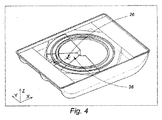
上述したようなキャリッジ(5)は、有利には、複数の角度セクター(36)へと分割することができる。それらの角度セクター(36)は、互いに同様の原理に基づいてそれぞれ独立に構成される。複数の角度セクター(36)は、例えば図4に示すように、互いに寄せ集めることができる。また、複数の角度セクター(36)は、例えば図5に示すように、レール(6)に沿って互いに離間させることができる。離間距離は、可動質量の偏心度合いを低減させる。レール(6)の周縁上にわたって複数の角度セクター(36)をバランス良く分散させることは、キャリッジ(5)の重心(26)を、中心軸線(3)の近傍へと、引き寄せる効果を有している。これにより、デバイスの不動化が容易とされるとともに、ブレーキによって停止場所へとデバイスをロックすることが容易とされる。複数の角度セクター(36)の相対変位は、モータシステムによって行われる。モータシステムは、典型的には、ウォームデバイスや他の任意の制御デバイスによって駆動されるキャプスタンやシャフトによって操作されるワイヤから構成される。これにより、キャリッジ(5)の偏心度合いを、波の性質に適合させることができる。穏やかな海の場合には、小さな偏心度合いが、回転を誘起するのに適切である。 The carriage (5) as described above can advantageously be divided into a plurality of angular sectors (36). These angular sectors (36) are independently constructed based on the same principle. The plurality of angular sectors (36) can be gathered together, for example as shown in FIG. Further, the plurality of angular sectors (36) can be separated from each other along the rail (6) as shown in FIG. 5, for example. The separation distance reduces the degree of eccentricity of the movable mass. Distributing the angular sectors (36) in a balanced manner over the periphery of the rail (6) has the effect of pulling the center of gravity (26) of the carriage (5) closer to the central axis (3). Yes. This facilitates the immobilization of the device and makes it easy to lock the device to the stop location by the brake. The relative displacement of the plurality of angular sectors (36) is performed by a motor system. A motor system typically consists of a wire operated by a capstan or shaft driven by a worm device or any other control device. Thereby, the degree of eccentricity of the carriage (5) can be adapted to the nature of the wave. In the case of a calm sea, a small degree of eccentricity is adequate to induce rotation.
本発明においては、変換デバイスは、キャリッジ(5)に対して固定された発電機(8)を備えている。発電機(8)は、キャリッジ(5)の質量に寄与することができる。発電機(8)の軸線は、軌道に沿ったすべての位置において、中心軸線(3)に対して平行なままである、あるいは、中心軸線(3)に対して交差したままである。発電機(8)には、ピニオン(27)付きのシャフトが設けられている。このピニオン(27)は、レール(6)に対して同軸的な円を描くギヤラック(9)に対して、噛合する。キャリッジ(5)の軌道運動は、発電機(8)のシャフトの急速な回転を誘起する。 In the present invention, the conversion device comprises a generator (8) fixed to the carriage (5). The generator (8) can contribute to the mass of the carriage (5). The axis of the generator (8) remains parallel to the central axis (3) or crosses the central axis (3) at all positions along the track. The generator (8) is provided with a shaft with a pinion (27). The pinion (27) meshes with a gear rack (9) that draws a circle coaxial with the rail (6). The orbital movement of the carriage (5) induces a rapid rotation of the generator (8) shaft.
ピニオン(27)の直径は、発電機(8)の経済的サイズに応じた減速比が得られるように、特に、低減された極数に応じた減速比が得られるように、選択される。 The diameter of the pinion (27) is selected such that a reduction ratio according to the economic size of the generator (8) is obtained, in particular a reduction ratio according to the reduced number of poles.
有利には、第2のラックピニオンシステムを、発電機(8)のシャフトの反対側の端部に、第1のラックピニオンシステムに対して対称的に設けることができる。これにより、応力をより良好に分散させることができる。 Advantageously, a second rack and pinion system can be provided symmetrically with respect to the first rack and pinion system at the opposite end of the generator (8) shaft. Thereby, a stress can be disperse | distributed more favorably.
様々な構成部材に起こり得る不規則性に対抗するために、本発明は、サスペンションシステムを介して、キャリッジ(5)に対して発電機(8)を連結する。このサスペンションシステムは、ピニオン(27)をギヤラック(9)に対して当接した状態に保持する。さらに、発電機(8)の固定子は、有利には、1つまたは2つのアイドラーホイールを有している。アイドラーホイールは、レール(6)の1つまたは2つの回転経路(23)に対して押圧されるとともに、深さガイドとして機能し、発電機(8)のサスペンションによって引き起こされるギヤラック(9)上へのピニオン(27)の径方向圧力を回避することができる。この最後の手段は、摩擦損失を低減し得る点において、および、ラックピニオンアセンブリの機械的摩耗を最小化し得る点において、効果的である。 In order to counter the irregularities that can occur in the various components, the present invention connects the generator (8) to the carriage (5) via a suspension system. This suspension system holds the pinion (27) in contact with the gear rack (9). Furthermore, the stator of the generator (8) advantageously has one or two idler wheels. The idler wheel is pressed against one or two rotation paths (23) of the rail (6) and functions as a depth guide onto the gear rack (9) caused by the suspension of the generator (8). The radial pressure of the pinion (27) can be avoided. This last measure is effective in that it can reduce friction losses and in that it can minimize the mechanical wear of the rack and pinion assembly.
本発明においては、発電機(8)とモジュールの静止部材との間の電気的接続は、円形スライドコンタクト(28)によって、典型的には一組をなす複数のスリップリングによってあるいはカテナリーシステムによって、行われる。 In the present invention, the electrical connection between the generator (8) and the stationary member of the module is made by a circular slide contact (28), typically by a set of slip rings or by a catenary system. Done.
波力エネルギーの定量的な抽出には、複数の波のうちの1つの波に対しての、キャリッジ(5)の運動の同期化が必要とされる。本発明は、発電機(8)のための制御システムを提供する。この制御システムは、とりわけキャリッジ(5)の速度特性を保証するものであって、軌道運動中における船体(1)の船首(11)および船尾(12)の各々のアプローチの減速度合いや、波の振動に対しての変換サイクルの同期化といったようなものを保証する。この振動内には様々な速度が含有されていることのために、発電機を、分散ネットワークに対して直接的に接続することはできない。 Quantitative extraction of wave energy requires synchronization of the movement of the carriage (5) with respect to one of the plurality of waves. The present invention provides a control system for the generator (8). This control system guarantees, among other things, the speed characteristics of the carriage (5), the degree of deceleration of each approach of the bow (11) and stern (12) of the hull (1) during orbital motion, Guarantee such things as synchronization of the conversion cycle to vibration. Due to the various speeds contained within this vibration, the generator cannot be connected directly to the distributed network.
本発明においては、必須ではないものの有利な態様においては、デバイスの内部に、電子的整流器が設けられる。これにより、消費者に向けてのあるいは分散ステーションに向けての送電を、直流によって、海底ケーブルを通して行うことができる。 In the present invention, but not essential, in an advantageous embodiment, an electronic rectifier is provided inside the device. As a result, power can be transmitted to the consumer or to the distribution station by direct current through the submarine cable.
必要であれば、例えば海岸線といったようなラインの端部のところに、インバータを配置することができる。これにより、制御されたAC電圧を生成することができる。これにより、グリッドに対しての接続に互換的なものとすることができる。 If necessary, an inverter can be placed at the end of the line, such as the coastline. Thereby, a controlled AC voltage can be generated. As a result, the connection to the grid can be made compatible.
本発明においては、制御システムは、少なくとも、
−キャリッジ(5)用の位置センサと、
−モジュールの傾斜の瞬時値を測定するためのセンサと、
−入力波の周波数を観測するためのセンサと、
−発電機(8)を制御するための電子回路と、
を備えている。
In the present invention, the control system is at least
A position sensor for the carriage (5);
A sensor for measuring the instantaneous value of the inclination of the module;
-A sensor for observing the frequency of the input wave;
An electronic circuit for controlling the generator (8);
It has.
この最小の構成は、有利には、リアルタイムで発電機(8)の電気的変数を測定するためのセンサを設けることによって、完成することができる。そのようなセンサは、より適合したコマンドセットを生成することができる。 This minimal configuration can advantageously be completed by providing sensors for measuring the electrical variables of the generator (8) in real time. Such a sensor can generate a more adapted command set.
上述したような生成ロジックにおいては、本発明は、個々の励起に対して発電機(8)を同期させるという利点を有することができる。これにより、トルクを正確に制御することができる。これとともに、この手段によって、キャリッジ(5)の速度特性を正確に制御することができる。より詳細には、低消費電力タイプのサーボ制御DC電源を使用することにより、回転子のインダクターを励起することができる。 In the generation logic as described above, the present invention can have the advantage of synchronizing the generator (8) to the individual excitations. Thereby, the torque can be accurately controlled. At the same time, the speed characteristic of the carriage (5) can be accurately controlled by this means. More specifically, the rotor inductor can be excited by using a low power consumption type servo-controlled DC power supply.
本発明は、さらに、キャリッジ(5)の移動速度の変化にかかわらず発電機(8)の一定の回転速度を維持し得る付加的な機械的デバイスを備えている。軌道上における可変減速比は、図7に示すように、ギヤラック(9)を、特定の可変ピッチのギヤラックシステムへと変更することによって、得られる。 The invention further comprises an additional mechanical device that can maintain a constant rotational speed of the generator (8) regardless of changes in the speed of movement of the carriage (5). The variable reduction ratio on the track is obtained by changing the gear rack (9) to a gear rack system having a specific variable pitch, as shown in FIG.
本発明においては、この特定の構成は、発電機(8)のシャフトに対して固定された長尺の円錐台形状ピニオン(27)を利用している。ピニオン(27)は、異なる直径の一組をなす複数の同軸ピニオンと等価である。ギヤラック(9)の歯付きラック(31)が、他の部分ではなくピニオン(27)の一部分に対して噛合していることのために、乗法比率が変化する。より具体的には、ギヤラック(9)は、それ自体が、ピニオン(28)に対して相補的な円錐台を提供する。しかしながら、軌道の所定ポイントのところでは、歯(31)は、円錐の母線の小さな部分しか占有しない。歯(31)どうしの間の間隔は、ピニオンのうちの、歯が噛合している部分のピッチ(10)に適合する。 In the present invention, this particular configuration utilizes a long frustoconical pinion (27) fixed to the shaft of the generator (8). The pinion (27) is equivalent to a plurality of coaxial pinions that make a set of different diameters. The multiplicative ratio changes because the toothed rack (31) of the gear rack (9) meshes with a portion of the pinion (27) rather than the other portion. More specifically, the gear rack (9) itself provides a truncated cone that is complementary to the pinion (28). However, at a given point in the trajectory, the tooth (31) occupies only a small part of the cone bus. The spacing between the teeth (31) matches the pitch (10) of the portion of the pinion where the teeth are engaged.
このようにして、歯(31)どうしの間のピッチ(10)は、したがって、ラックピニオンアセンブリの減速比は、連続的に可変であり、キャリッジ(5)の参照速度特性に対して相関した機械的適合を提供することができる。 In this way, the pitch (10) between the teeth (31) and therefore the reduction ratio of the rack and pinion assembly is continuously variable and is correlated to the reference speed characteristic of the carriage (5). Can be provided.
固定ピッチを有したギヤラックと比較して複雑さが増大しているにもかかわらず、発電機(8)が受ける機械的擾乱の減衰は、通常の運転条件に対してより近い動作を行い得るという利点をもたらすことができる。よって、経済的なサイズとし得るという利点をもたらすことができる。 Despite the increased complexity compared to gear racks with a fixed pitch, the attenuation of the mechanical disturbance experienced by the generator (8) can be closer to normal operating conditions. Can bring benefits. Therefore, the advantage that it can be set as an economical size can be brought about.
大量生産に関し、本発明は、複数のモジュールのネットワーク化を可能とし、ファームとして構成することができる。位置的に近接して配置されることによる複数のモジュールの集積化は、有利には、いくつかの周辺システムの共有を可能とし得るとともに、メンテナンス操作の共有を可能とすることができる。 Regarding mass production, the present invention enables networking of a plurality of modules and can be configured as a farm. The integration of multiple modules by being placed in close proximity may advantageously allow sharing of several peripheral systems as well as sharing of maintenance operations.
同一のファーム内の複数のモジュールは、ロープやチェーンや連結ロッドを介して、水面上において、メッシュパターンでもって配置することができる。これにより、ファームを所定位置に維持するための手段や係留システム(16)等を、共有することができる。 A plurality of modules in the same farm can be arranged with a mesh pattern on the water surface via a rope, a chain or a connecting rod. Thereby, the means for maintaining the farm in a predetermined position, the mooring system (16), and the like can be shared.
さらに、電力を送電したり整形したりするための手段を、各モジュールの整流器の下流側において共有することができる。これにより、スケールメリットを得ることができる。さらに、上述したように(図7)、一組をなす複数の可変ピッチのギヤラックを使用することにより、同一の整流器を共有することができる。なぜなら、波の周波数が、連結されたすべてのモジュールに対して共通であるからである。これにより、集合的な電力出力を円滑化することができる。この場合、ファーム内の様々な発電機(8)どうしの間にわたってのサイクルフェーズ(図8a〜図8d)の同期は、実際に不要であり、様々なモジュールは、電気的なミスマッチというリスクなく、個別のフロント上に配置することができる。 Furthermore, means for transmitting and shaping power can be shared downstream of the rectifiers of each module. Thereby, a scale merit can be obtained. Furthermore, as described above (FIG. 7), the same rectifier can be shared by using a plurality of variable pitch gear racks. This is because the wave frequency is common to all connected modules. Thereby, collective power output can be smoothed. In this case, the synchronization of the cycle phases (FIGS. 8a-8d) across the various generators (8) in the farm is actually unnecessary, and the various modules are not at risk of electrical mismatch, Can be placed on a separate front.
さらに、整流器の上流側におけるモジュールどうしの相互接続により、格別の駆動作用を得ることができる。これは、特に低振幅の波上におけるキャリッジ(5)の移動セットシーケンス時において、制御計画の数を大幅に延長させる。 Furthermore, an exceptional driving action can be obtained by the interconnection of the modules on the upstream side of the rectifier. This greatly extends the number of control plans, especially during the moving set sequence of the carriage (5) on low amplitude waves.
さらに、定常状態においては、変換サイクルの規則性は、集合的効果によって改良される傾向がある。 Furthermore, in steady state, the regularity of the conversion cycle tends to be improved by the collective effect.
本発明においては、振動バラスト(4)からなる経済的デバイスにより、電力抽出を実質的に改良することができる。 In the present invention, the power extraction can be substantially improved by an economical device comprising the vibration ballast (4).
重要な質量が与えられ、波に抗するように制御された移動が与えられると、キャリッジ(5)は、モジュールの縦揺れ運動を著しく低減させる。これは、効率を大幅に下落させる。それ自体の重量の作用によって軸線X方向に沿って並進移動する振動的平衡錘により、縦揺れ運動時のキャリッジ(5)の効果を補償することができ、増幅することさえできる。 Given significant mass and given controlled movement against the waves, the carriage (5) significantly reduces the pitching motion of the module. This greatly reduces efficiency. The effect of the carriage (5) during the pitching movement can be compensated and even amplified by a vibrating balance weight that translates along the axis X direction by the action of its own weight.
非限定的な好ましい実施形態においては、図1に示すように、本発明は、船体(12)の船首から船尾までを連結する軸線X方向の一組をなす複数の平行直線ダクト(32)として配置することにより、モジュール構成空間の全部または一部を利用する。ダクト(32)は、水によって部分的に充填される。これにより、可動バラスト(4)を構成することができる。その流れは、波と一緒に、自然的に振動する。このデバイスにより、一方においては、縦揺れ運動を増幅することができ、他方においては、図8bおよび図8dに示す最大傾斜フェーズの持続時間を延ばすことができる。図8aおよび図8cに示すような傾斜増大フェーズおよび傾斜減少フェーズの際のバラスト(4)の速い流れは、モジュールの最も低い端部における一時的な停滞をもたらす。このようにして、振動バラスト(4)は、最大傾斜位置における安定化に寄与するとともに、最適傾斜条件においては、キャリッジ(5)の降下のための時間を長くする。 In a preferred non-limiting embodiment, as shown in FIG. 1, the present invention is as a plurality of parallel straight ducts (32) forming a set in the direction of the axis X connecting the bow (12) from the bow to the stern. By arranging, all or part of the module configuration space is used. The duct (32) is partially filled with water. Thereby, movable ballast (4) can be constituted. The flow naturally oscillates along with the waves. With this device, on the one hand, the pitching motion can be amplified, and on the other hand, the duration of the maximum tilt phase shown in FIGS. 8b and 8d can be increased. The fast flow of the ballast (4) during the ramp up and ramp down phases as shown in FIGS. 8a and 8c results in a temporary stagnation at the lowest end of the module. In this way, the vibration ballast (4) contributes to stabilization at the maximum tilt position and lengthens the time for the carriage (5) to descend under the optimal tilt condition.
ダクト(32)が全体的に長尺形状であることは、横揺れ運動に寄与することなく、縦揺れ運動に寄与するものであって、好ましい。 It is preferable that the duct (32) has an overall long shape, which contributes to the pitching motion without contributing to the rolling motion.
本発明の思慮深い実施形態においては、バラスト(4)を収容したダクト(32)は、船体(1)を構成するリブに対して組み合わされる。 In a thoughtful embodiment of the invention, the duct (32) containing the ballast (4) is combined with the ribs constituting the hull (1).
そのような構成の興味は、そのような構成が提供する安価な制御可能性である。実際、ダクト(32)内におけるエア比率は、ダクト内のバラスト(4)の流体力学的振る舞いを決定する。 The interest of such a configuration is the cheap controllability that such a configuration provides. In fact, the air ratio in the duct (32) determines the hydrodynamic behavior of the ballast (4) in the duct.
本発明は、この点において、有利には、ダクト(32)を複数の個別隔室へと分割し得ることを提供する。図1に示す特別の場合には、第1隔室(33)は、船体(1)の中央部分を占有し、第2隔室(34)は、船体(1)の両サイドにおいて2つの対称的な廊下を占有する。 The invention advantageously provides in this respect that the duct (32) can be divided into a plurality of individual compartments. In the special case shown in FIG. 1, the first compartment (33) occupies the central part of the hull (1) and the second compartment (34) is two symmetrical on both sides of the hull (1). Occupy a typical corridor.
同じ隔室内におけるダクト(32)の一様な充填レベルは、隣接するダクト(32)どうしの間に形成された開口(37)によって、および、図2に示す一組をなす複数のパイプ(35)によって、得られる。パイプは、第2隔室(34)の2つの部分を連通させている。 The uniform filling level of the ducts (32) in the same compartment is determined by the openings (37) formed between the adjacent ducts (32) and the multiple pipes (35) in the set shown in FIG. ) To obtain. The pipe communicates the two parts of the second compartment (34).
本発明においては、制御された双方向性ポンピングシステムは、隔室(33,34)間にわたってのバラスト(4)の移送を確保し、これにより、モジュール全体の縦揺れ運動特性を調節することができる。これにより、入力波の特性に応じた最適の抽出条件を確保することができる。部分的に充填された隔室の重心は、モジュールのX軸線に沿って移動する。逆に、全体的に充填された隔室あるいは空虚な隔室は、不活性であり、よって、縦揺れ運動には寄与しない。 In the present invention, the controlled bidirectional pumping system ensures the transfer of the ballast (4) between the compartments (33, 34), thereby adjusting the pitching motion characteristics of the entire module. it can. Thereby, the optimal extraction conditions according to the characteristics of the input wave can be ensured. The center of gravity of the partially filled compartment moves along the X axis of the module. Conversely, a totally filled compartment or an empty compartment is inactive and thus does not contribute to pitching motion.
したがって、バラスト(4)のポンピングデバイスは、嵐の時に、あるいは、メンテナンス操作時に、モジュールの安全性を維持するための手段を提供する。これは、一方の隔室(33,34)内へのバラスト(4)の全移送のためである。 Thus, the ballast (4) pumping device provides a means to maintain the safety of the module during storms or during maintenance operations. This is due to the total transfer of the ballast (4) into one of the compartments (33, 34).
本発明においては、上記のすべての構成に適合した付加的な構成であるとともに、同一のモジュール内において2つの個別セットのレール(6)上において互いに逆向きに回転する2つの同様のキャリッジ(5)を使用した付加的な構成により、船体(1)の横揺れ運動を意義深く低減することができる。そのような構成においては、実際、2つのキャリッジ(5)は、X軸線に関して対称的な運動をするように、制御される。これにより、これら2つの質量の全体の重心は、同じ軸線X方向に沿ってのみ振動する。 In the present invention, two similar carriages (5) which are additional configurations adapted to all the above configurations and which rotate in opposite directions on two separate sets of rails (6) in the same module. ) Can significantly reduce the rolling motion of the hull (1). In such a configuration, in fact, the two carriages (5) are controlled to move symmetrically with respect to the X axis. Thereby, the center of gravity of the whole of these two masses vibrates only along the same axis X direction.
ガイドラインとして、本発明を何ら限定することなく、2セットのレールは、典型的には、同軸的に重ね合わされる、あるいは、同一平面的とされてモジュールの長手方向軸線Xに関して対称的なものとされる。 As a guideline, without limiting the invention in any way, the two sets of rails are typically coaxially superimposed or coplanar and symmetrical with respect to the longitudinal axis X of the module. Is done.
1 船体
2 蓋
4 振動バラスト
5 キャリッジ
6 レール
7 支持ローラ
8 発電機
9 ギヤラック
11 船首
12 船尾
13 バルジ
15 平行フィン
17 ベアリング
18 サスペンション
22 円筒形ローラ
24 ベアリング
26 サスペンション
27 ピニオン
28 スライドコンタクト
30 アイドラーホイール
31 歯
32 長手方向ダクト
35 パイプ
36 角度セクター
37 開口
1 Hull 2 Lid 4
現在まで、様々な波力エネルギーシステムが考案されて開発されてきた。しかしながら、期待される性能に見合った実用的応用には至っていない。 To date, various wave energy systems have been devised and developed. However, it has not reached a practical application commensurate with the expected performance.
既存の発明の様々な分類どうしを比較することにより、機能的なおよび経済的な開発可能性の観点から最も有用な特徴点を識別することができ、それぞれの限界を分析することができる。これにより、波力エネルギーを電力へと効率的に変換するのに必要な実施や操作に関する実用的条件を満たす新たなデバイスを開発することができる。 By comparing various classifications of existing inventions, the most useful feature points can be identified in terms of functional and economic development possibilities, and their respective limits can be analyzed. Thereby, it is possible to develop a new device that satisfies a practical condition regarding implementation and operation necessary for efficiently converting wave energy into electric power.
よって、単一の浮遊ボディ内にデバイスの全体を包含させるという原理によって、海底基礎の問題点を回避することができ、さらに、外部構成部材を有していないことによって、システムの頑丈さが保証されるとともに海洋環境への適合が保証されることが、見出された。 Thus, the principle of enclosing the entire device in a single floating body avoids the problems of submarine foundations, and the absence of external components ensures the robustness of the system And found to be compatible with the marine environment.
その他にも、油圧伝達構成部材を設けることなく、直接的な電気機械的変換というある種の態様とすることにより、単純な実施態様および単純な操作によって、固体の移動を利用することができる。 In addition, the solid movement can be utilized by a simple embodiment and a simple operation by providing a certain type of direct electromechanical conversion without providing a hydraulic transmission component.
このような変換方法を全体的にあるいは部分的に使用した特許文献について、以下のものに言及することができる。
−特許文献1:波と一緒に縦揺れする浮遊物体であるとともに、その縦揺れを偏心ドライブへと伝達して、水平方向平面内において振り子式に振動させる。
−特許文献2,3:1つまたは複数の偏心物体であるとともに、波の振動の結果として、水平方向平面内において、全回転を行い、逆回り回転を行わない。
The following can be mentioned about the patent document which used such a conversion method in whole or in part.
Patent Document 1: A floating object that pitches with a wave, and transmits the pitch to an eccentric drive to vibrate in a pendulum manner in a horizontal plane.
Patent Documents 2 and 3: One or more eccentric objects, and as a result of wave vibration, perform full rotation and no reverse rotation in the horizontal plane.
操作という観点から、上記のタイプのシステムにおける限界には、主として、以下のようなものがある。
−デバイスを移動状態にセットするに際し、大部分の波の態様を利用することが困難であること。
−発電機のための定常的操作レジームを維持するに際し、波の周波数に対してデバイスを同期させることが困難であること。
−様々な構成部材どうしの間における摩擦のために、損失が発生すること。
これらの限界の合計のために、生産ロジックにおける全体的収率が低下してしまうこととなる。
From an operational point of view, the limitations in the above type of system are mainly as follows.
-It is difficult to use most wave modes when setting the device in the moving state.
-It is difficult to synchronize the device to the wave frequency in maintaining a steady operating regime for the generator.
-Loss occurs due to friction between the various components.
The sum of these limits will reduce the overall yield in production logic.
本明細書においては、本発明は、一組をなす複数の解決手法を規定するものであり、とりわけ、波の周波数に対しての電力抽出デバイスの同期を最適化するための様々なフレキシブルさと、小さな摩擦での構成部材の使用と、慣習的なエンジニアリング技術および製造技術の使用と、安価な材料やリサイクル材料の使用と、最小で容易なメンテナンスと、を提供する。 In the present specification, the present invention defines a set of solutions, in particular various flexibility to optimize the synchronization of the power extraction device to the wave frequency, It provides the use of components with low friction, the use of conventional engineering and manufacturing techniques, the use of inexpensive materials and recycled materials, and minimal and easy maintenance.
本発明の主題をなす波力エネルギー変換器は、実質的に浮遊型の閉塞ボディから構成され、このボディは、波の振動から電力を生成するための電気的機械的変換デバイスを全体的に収容している。 The wave energy converter that forms the subject of the present invention consists essentially of a floating occluded body, which generally contains an electromechanical conversion device for generating electrical power from wave vibrations. doing.
船体は、あるいはボディの浸漬部分は、係留される、すなわち、モータ付きデバイスによって所定位置に保持される。一組をなす複数のフィンが設けられ、これにより、波頭に対向した配向性が一定に維持される。船体は、波の上下動に応じて、モジュールの縦揺れ運動に適した格別の形状を有している。説明の簡略化のために、船体のうちの、入力波に対して最初に接触する部分は、本明細書では、モジュールの前方部分と称され、すなわち、船首と称されることに、また、反対側の部分は、モジュールの後方部分と称され、すなわち、船尾と称されることに、注意されたい。 The hull or the immersed part of the body is moored, i.e. held in place by a motorized device. A plurality of fins forming a set is provided, whereby the orientation facing the wave front is kept constant. The hull has a special shape suitable for the pitching motion of the module according to the vertical movement of the wave. For simplicity of explanation, the portion of the hull that first contacts the input wave is referred to herein as the front portion of the module, ie, referred to as the bow, and Note that the opposite portion is referred to as the rear portion of the module, ie, the stern.
ボディの内部においては、偏心質量は、錘キャリッジの態様とされ、一組をなす複数の円形レールに沿って移動することができる。この種の構成により、中央キャリングシャフトを不要とすることができる。これにより、中央の回転軸線上における偏心質量の意義深い曲げモーメントに起因する摩擦を回避することができる。 Inside the body, the eccentric mass is in the form of a weight carriage and can move along a set of circular rails. This type of configuration can eliminate the need for a central carrying shaft. Thereby, the friction resulting from the significant bending moment of the eccentric mass on the central rotation axis can be avoided.
ボディの縦揺れ運動は、レールがなす平面を傾斜させ、これにより、キャリッジの重量の効果のために、キャリッジを移動させてしまう。例えば振り子運動の際に起こるような、軌道上のブレークポイントすなわち反転ポイントの存在に特有の電気的機械的問題点に打ち勝ち得るよう、本発明は、中央軸線まわりにおけるキャリッジの完全な軌道すなわち妨害されていない軌道の利点を有することができる。 The pitching motion of the body tilts the plane formed by the rails, thereby moving the carriage due to the effect of the weight of the carriage. In order to overcome the electromechanical problems unique to the presence of breakpoints or reversal points on the trajectory, such as occur during pendulum movement, the present invention provides a complete trajectory or obstruction of the carriage around the central axis. Not have the advantage of a trajectory.
運動時に偏心質量が獲得する運動エネルギーは、軌道がなす平面を傾斜させることによって波が偏心質量を持ち上げた際の位置エネルギーに依存する。 The kinetic energy acquired by the eccentric mass during movement depends on the potential energy when the wave lifts the eccentric mass by tilting the plane formed by the trajectory.
軌道の傾斜の大きさが小さいことのために、摩擦が、ある種の波の高さ以下の場合に乗り越えられなくなり得る主要な制限である。この点に関し、本発明は、キャリッジが移動する際の摩擦損失を低減することを目的とした一組をなす複数の構成を提供する。 Because of the small magnitude of the trajectory slope, friction is a major limitation that can be overcome when below certain wave heights. In this regard, the present invention provides a plurality of configurations for the purpose of reducing friction loss when the carriage moves.
集積された運動エネルギーは、キャリッジに対して一体化された発電機によって変換される。発電機シャフトは、レールと同軸的な一組をなす複数のギヤラックに対して噛合した1つまたは2つのコグホイールによって、回転駆動される。スライドコンタクトが、発電機を、電気的整流器に対して接続する。これにより、地上の分配ステーションに対してのモジュールの電気的接続は、海洋環境を通しての交流送電に起因するライン損失を回避する。 The accumulated kinetic energy is converted by a generator integrated with the carriage. The generator shaft is rotationally driven by one or two cog wheels that mesh with a plurality of gear racks that are coaxial with the rail. A slide contact connects the generator to the electrical rectifier. Thereby, the electrical connection of the module to the distribution station on the ground avoids line losses due to AC power transmission through the marine environment.
可動バラストも、また、波の上下動によって、駆動される。可動バラストは、入力波の向きにおけるモジュールの傾斜を増大させる。これにより、キャリッジの落下高さを増大させる。 The movable ballast is also driven by the up and down movement of the waves. The movable ballast increases the slope of the module in the direction of the input wave. This increases the fall height of the carriage.
この傾斜位置に起因する電力抽出サイクルは、概略的には、以下の4つのフェーズに分解することができる。
−入力波の効果によって傾斜が増大するフェーズにおいて、キャリッジの軌道を、船首の近傍に位置させ、これにより、キャリッジに、重力に基づく位置エネルギーを獲得させるフェーズ。
−モジュールが最大傾斜に到達した後に、キャリッジを下向きに加速させながら、位置エネルギーを運動エネルギーへと変換するフェーズ。このフェーズは、短いものである。なぜなら、最大傾斜が一時的であるからである。
−モジュールが波頭を乗り越えたことのために傾斜が減少するフェーズにおいて、キャリッジの軌道を、船尾の近傍に位置させ、これにより、キャリッジに、重力に基づく位置エネルギーを再び獲得させるフェーズ。
−波が船尾を持ち上げることのために、モジュールが最大傾斜に到達した後に、キャリッジを加速させながら、位置エネルギーを再び運動エネルギーへと変換するフェーズ。
The power extraction cycle resulting from this tilt position can be roughly broken down into the following four phases.
A phase in which the trajectory of the carriage is positioned in the vicinity of the bow in a phase where the tilt increases due to the effect of the input wave, thereby causing the carriage to acquire gravitational potential energy.
Phase after the module reaches maximum tilt, converting potential energy into kinetic energy while accelerating the carriage downwards. This phase is short. This is because the maximum slope is temporary.
A phase in which the trajectory of the carriage is positioned in the vicinity of the stern in a phase where the inclination decreases due to the module overcoming the wavefront, thereby causing the carriage to regain the potential energy based on gravity.
A phase in which the potential energy is converted back into kinetic energy while accelerating the carriage after the module reaches the maximum tilt for the waves to lift the stern.
よって、効率的な波力エネルギー抽出のためには、キャリッジ速度を可変とする必要がある。カバーされた距離は、短いフェーズにおいては、やや長いものであり、長いフェーズにおいては、やや短いものである。 Therefore, it is necessary to make the carriage speed variable for efficient wave energy extraction. The covered distance is slightly longer in the short phase and slightly shorter in the long phase.
同一サイクルの途中におけるキャリッジの速度変動にかかわらず、発電機シャフトを一定の速度で駆動させるためには、一組をなす複数の可変ピッチのギヤラックの恩恵を受けることができる。そのような可変ピッチのギヤラックは、機械的なアダプタとして機能するものであって、低減比率の連続的な変化を可能とする。これにより、そのようなデバイスにおいては、発電機を、公称規格に近い条件で動作させることができる。 Regardless of the speed variation of the carriage during the same cycle, in order to drive the generator shaft at a constant speed, one can benefit from a set of variable pitch gear racks. Such a variable-pitch gear rack functions as a mechanical adapter and allows a continuous change in the reduction ratio. Thereby, in such a device, the generator can be operated under conditions close to the nominal specification.
さらに、サーボ制御デバイスにより、経時的な変動に基づく波の周波数に対して、キャリッジの回転周期を連続的に同期させることができる。 Further, the servo control device can continuously synchronize the rotation period of the carriage with respect to the wave frequency based on the fluctuation over time.
本発明の様々な特定の特徴点につき、添付図面を参照しつつ、本発明を何ら限定することなく、以下において説明する。 Various specific features of the present invention will be described below without limiting the present invention in any way with reference to the accompanying drawings.
本発明においては、波力エネルギー変換モジュールは、蓋(2)によって閉塞された船体(1)からなる水密ボディを備えている。水密ボディは、敏感な構成部材が海洋環境に対して直接的に曝されないような態様で、一組をなす複数の電気的機械的構成部材を収容している。 In the present invention, the wave energy conversion module includes a watertight body including a hull (1) closed by a lid (2). The watertight body contains a set of electromechanical components in such a manner that sensitive components are not directly exposed to the marine environment.
ボディ(1,2)は、図1に示すように、嵩低いものであって、丸められたエッジを有した矩形の浮遊物体とされており、海の表面上を浮遊する。ボディの流体力学的形状は、とりわけ船体(1)の底面の形状は、波に起因する縦揺れ運動を増強し得るよう構成されている。 As shown in FIG. 1, the bodies (1, 2) are low in volume and are rectangular floating objects with rounded edges, and float on the surface of the sea. The hydrodynamic shape of the body, in particular the shape of the bottom of the hull (1), is configured to enhance the pitching motion caused by the waves.
モジュールに対して相対的に固定されたような、3次元座標系は、3つの軸線(X,Y,Z)によって識別される。縦揺れ運動時には、X軸線の方向は、平均的に、波の伝搬方向に一致し、Z軸線の方向は、平均的に、鉛直方向に一致し、Y軸線の方向は、平均的に、上記の2つの方向に対して垂直とされる。縦揺れ運動は、波の作用に起因するものであって、Y軸線まわりの周期的な回転に対応する。 A three-dimensional coordinate system, such as fixed relative to the module, is identified by three axes (X, Y, Z). During the pitching motion, the X-axis direction is, on average, coincident with the wave propagation direction, the Z-axis direction is, on average, coincident with the vertical direction, and the Y-axis direction is, on average, the above-described direction. Are perpendicular to the two directions. The pitching motion is caused by the action of waves and corresponds to a periodic rotation around the Y axis.
船体(1)と交差したときには、入力波は、船首(11)を持ち上げると同時に、船尾を沈ませる。船首は、持ち上げられやすいスパチュラ形状とされていることが有利であり、これにより、波を切るのではなくて、波の頂部上に乗り上げることができる。船体(1)の底面は、図3に示すように、バルジ(13)を特徴としている。バルジ(13)は、好ましくは、船尾に向けて位置している。バルジ(13)は、波の通過時には、ベンチュリ効果によって、低圧を生成する。この低圧は、底面に向けて船体(1)の船尾を吸引することに寄与し、これにより、波状におけるモジュールの傾斜を増大させる。 When crossing the hull (1), the input wave raises the bow (11) and simultaneously sinks the stern. The bow is advantageously shaped like a spatula that is easy to lift, so that it can ride on top of the waves rather than breaking the waves. The bottom of the hull (1) features a bulge (13) as shown in FIG. The bulge (13) is preferably located towards the stern. The bulge (13) generates a low pressure due to the venturi effect when the wave passes. This low pressure contributes to sucking the stern of the hull (1) towards the bottom, thereby increasing the slope of the module in the undulation.
波の頂上においては、船体(1)が、波を乗り越え、船首(11)が、次の波の谷内へと飛び込んでいく。これとともに、バルジ(13)上における低圧は、船尾のところにおける水の排出とともに消えていく。これにより、浮力が、船尾を表面へと引き戻す。ある種の共鳴が発生する。船尾(12)のより深い沈み込みに対しては、流体の作用によって、より強い押し上げが応答する。 At the top of the wave, the hull (1) gets over the wave and the bow (11) jumps into the next wave valley. At the same time, the low pressure on the bulge (13) disappears with the discharge of water at the stern. This causes buoyancy to pull the stern back to the surface. Some kind of resonance occurs. For deeper subsidence of the stern (12), a stronger push-up responds due to the action of the fluid.
本発明においては、船体(1)の幾何形状は、入力波(14)の方向に関しての優先方向を提供する。この理由のために、本発明は、船体(1)の底面に対して固定された一組をなす複数のフィン(15)を意図している。一組をなす複数のフィン(15)は、波頭に対してのモジュールの一定の配向性を保証する。一般的な縦揺れ運動にとって不利とならないように、フィン(15)は、船体(1)の底面の流れをチャネリングすることができる。これにより、ベンチュリ効果を増強することができる。 In the present invention, the hull (1) geometry provides a preferred direction with respect to the direction of the input wave (14). For this reason, the present invention contemplates a set of fins (15) fixed to the bottom of the hull (1). A set of fins (15) ensures a constant orientation of the module with respect to the wavefront. The fin (15) can channel the flow at the bottom of the hull (1) so as not to be disadvantageous for general pitching motion. Thereby, the venturi effect can be enhanced.
加えて、本発明は、係留システム(16)、あるいは、モジュールの地理的位置を維持するための他の任意の手段、を備えている。船体(1)の係留システムの1つまたは複数のアンカー止めポイントは、縦揺れ運動に逆らうのではなく縦揺れ運動に追従し得るように、配置されている。さらに、少なくとも2つの係留ラインが使用される場合には、係留システム(16)により、船体(1)の適正な配向性を補助することができる。これに代えて、例えば海が深すぎる場合には、衛星によって案内される小さなモータを使用した動的位置決めシステムを使用することもできる。 In addition, the present invention comprises a mooring system (16) or any other means for maintaining the geographical location of the module. One or more anchoring points of the mooring system of the hull (1) are arranged so that they can follow the pitching motion rather than against the pitching motion. Furthermore, if at least two mooring lines are used, the mooring system (16) can assist in the proper orientation of the hull (1). Alternatively, a dynamic positioning system using a small motor guided by a satellite can be used, for example when the sea is too deep.
ボディの蓋(2)は、メンテナンス操作のためのホストプラットホームとして設置され、この点において、例えば落下防止システムやハッチ(29)付きの着脱可能パネルといったような安全デバイスを提供する。 The body lid (2) is installed as a host platform for maintenance operations, and in this respect provides a safety device such as a fall prevention system or a detachable panel with a hatch (29).
船体(1)の寸法は、入力波の平均サイズに比例したものとされるとともに、収容した変換デバイスのサイズに比例したものとされる。非限定的な例示として、船体の長さは、波力エネルギー装置に適した波の上下動を考慮して、典型的には、15〜30mとされる。 The size of the hull (1) is proportional to the average size of the input wave and is proportional to the size of the accommodated conversion device. As a non-limiting example, the length of the hull is typically 15 to 30 m in consideration of the vertical movement of the wave suitable for the wave energy device.
本発明においては、デバイスは、三日月形状の偏心重量を有している。偏心重量のZ軸線まわりの円形運動は、船体(1)の縦揺れ運動によって連続的に維持される。 In the present invention, the device has a crescent-shaped eccentric weight. The circular motion of the eccentric weight around the Z-axis is continuously maintained by the pitching motion of the hull (1).
この偏心重量は、有利には、一組をなす複数の環状同軸レール上を移動するキャリッジ(5)から構成される。一方のレールは、少なくとも、支持体として機能し、一方のレールあるいは複数の付加的な相補レールは、水平軌跡上にキャリッジ(5)を維持することを保証する。非限定的な例示の目的のために、この一組をなす複数のレールは、互いに同じ直径を有した2つの重ね合わされたレール(6)という特定の態様として、例示されている。 This eccentric weight advantageously consists of a carriage (5) that moves on a set of annular coaxial rails. One rail serves at least as a support, and one rail or a plurality of additional complementary rails ensure that the carriage (5) is maintained on a horizontal trajectory. For non-limiting illustrative purposes, this set of rails is illustrated as a particular embodiment of two superimposed rails (6) having the same diameter as each other.
キャリッジ(5)とレール(6)との間の接触は、ベアリング(17)上に取り付けられたセットローラ(7)によって、確保される。ベアリングは、有利には、典型的にはワッシャやスプリングブレードといったような強度が大きく低い高さの経済的なサスペンション(18)上に取り付けることができる。これにより、レール(6)上における最終的な不規則性の影響を低減することができ、また、太陽および水の組合せ作用に起因する膨張率の差の影響を低減することができる。 Contact between the carriage (5) and the rail (6) is ensured by a set roller (7) mounted on the bearing (17). The bearing can advantageously be mounted on an economical suspension (18) of high strength and low height, typically a washer or spring blade. Thereby, the influence of the final irregularity on a rail (6) can be reduced, and the influence of the difference of the expansion coefficient resulting from the combined action of the sun and water can be reduced.
さらに、本発明は、レール(6)の表面上におけるスリップを引き起こすことなく、キャリッジ(5)のローラ(7)が回転することを保証することを、意図している。この目的のために、レールの回転経路(19)に対して接触したローラ(7)は、それ自体が、それぞれの回転経路(19)の中心(20)に対して一致した頂点を有した円錐台を提供する。このようにして、すべてのローラ(7)の軸線は、わずかに傾斜しており、回転経路(19)の中心(20)に位置したポイントへと収束する。 Furthermore, the present invention is intended to ensure that the roller (7) of the carriage (5) rotates without causing a slip on the surface of the rail (6). For this purpose, the roller (7) in contact with the rail rotation path (19) is itself a cone with a vertex that coincides with the center (20) of the respective rotation path (19). Provide a stand. In this way, the axes of all the rollers (7) are slightly inclined and converge to a point located at the center (20) of the rotation path (19).
径方向応力によって生成された摩擦を制限するために、キャリッジ(5)には、Z軸線に平行な相補的な組をなす円筒形ローラ(22)が設けられている。これらのローラは、レール(6)の側面(23)上における径方向支持体として、機能する。この目的のために、相補的な組をなすローラ(22)は、有利には、それ自体が、ベアリング(24)上におよびサスペンション(25)上に取り付けられる。各レール(6)の側面(23)は、回転経路として機能する。 In order to limit the friction generated by the radial stress, the carriage (5) is provided with a complementary cylindrical roller (22) parallel to the Z axis. These rollers function as radial supports on the side surface (23) of the rail (6). For this purpose, the complementary pair of rollers (22) is advantageously mounted on the bearing (24) and on the suspension (25). The side surface (23) of each rail (6) functions as a rotation path.
本発明においては、レール(6)の半径は、側方回転経路(23)上においてキャリッジ(5)によって引き起こされる応力ができる限り小さなものとなるものとされている。言い換えれば、キャリッジ(5)は、一方または双方のレール上において本質的にバランスされ、片持ちとなることがない。これを得るために、キャリッジ(5)の重心(26)は、ローラと支持レールとの間の接触ポイントによって規定されたコードおよびアークによって形成される三日月形状に対して、鉛直方向に配置されている。 In the present invention, the radius of the rail (6) is such that the stress caused by the carriage (5) on the lateral rotation path (23) is as small as possible. In other words, the carriage (5) is essentially balanced on one or both rails and cannot be cantilevered. To obtain this, the center of gravity (26) of the carriage (5) is arranged vertically relative to the crescent shape formed by the cord and arc defined by the contact point between the roller and the support rail. Yes.
キャリッジ(5)の質量を構成する材料の本質的な品質は、密度である。この要求は、安価な廃物材料の使用と一致する。本発明を何ら限定することなく例示するならば、典型的にはコンクリート内にキャスティングされた瓦礫とリサイクル対象物とのブレンドといったような非常に経済的な材料からなる複合質量や、例えばリサイクルされたキャストスチールといったような、より高密度で時にはより高価な材料が、キャリッジ(5)の中心軸線を中心とした周縁三日月上へと配置されて、経済的に興味のある手法を提供する。 The essential quality of the material constituting the mass of the carriage (5) is density. This requirement is consistent with the use of inexpensive waste materials. Illustrating the invention without any limitation, it is typically a composite mass consisting of a very economical material such as a blend of debris cast into concrete and the material to be recycled, eg recycled A denser and sometimes more expensive material, such as cast steel, is placed on the peripheral crescent moon about the central axis of the carriage (5) to provide an economically interesting approach.
上述したようなキャリッジ(5)は、有利には、複数の角度セクター(36)へと分割することができる。それらの角度セクター(36)は、互いに同様の原理に基づいてそれぞれ独立に構成される。複数の角度セクター(36)は、例えば図4に示すように、互いに寄せ集めることができる。また、複数の角度セクター(36)は、例えば図5に示すように、レール(6)に沿って互いに離間させることができる。離間距離は、可動質量の偏心度合いを低減させる。レール(6)の周縁上にわたって複数の角度セクター(36)をバランス良く分散させることは、キャリッジ(5)の重心(26)を、中心軸線(3)の近傍へと、引き寄せる効果を有している。これにより、デバイスの不動化が容易とされるとともに、ブレーキによって停止場所へとデバイスをロックすることが容易とされる。複数の角度セクター(36)の相対変位は、モータシステムによって行われる。モータシステムは、典型的には、ウォームデバイスや他の任意の制御デバイスによって駆動されるキャプスタンやシャフトによって操作されるワイヤから構成される。これにより、キャリッジ(5)の偏心度合いを、波の性質に適合させることができる。穏やかな海の場合には、小さな偏心度合いが、回転を誘起するのに適切である。 The carriage (5) as described above can advantageously be divided into a plurality of angular sectors (36). These angular sectors (36) are independently constructed based on the same principle. The plurality of angular sectors (36) can be gathered together, for example as shown in FIG. Further, the plurality of angular sectors (36) can be separated from each other along the rail (6) as shown in FIG. 5, for example. The separation distance reduces the degree of eccentricity of the movable mass. Distributing the angular sectors (36) in a balanced manner over the periphery of the rail (6) has the effect of pulling the center of gravity (26) of the carriage (5) closer to the central axis (3). Yes. This facilitates the immobilization of the device and makes it easy to lock the device to the stop location by the brake. The relative displacement of the plurality of angular sectors (36) is performed by a motor system. A motor system typically consists of a wire operated by a capstan or shaft driven by a worm device or any other control device. Thereby, the degree of eccentricity of the carriage (5) can be adapted to the nature of the wave. In the case of a calm sea, a small degree of eccentricity is adequate to induce rotation.
本発明においては、変換デバイスは、キャリッジ(5)に対して固定された発電機(8)を備えている。発電機(8)は、キャリッジ(5)の質量に寄与することができる。発電機(8)の軸線は、軌道に沿ったすべての位置において、中心軸線(3)に対して平行なままである、あるいは、中心軸線(3)に対して交差したままである。発電機(8)には、ピニオン(27)付きのシャフトが設けられている。このピニオン(27)は、レール(6)に対して同軸的な円を描くギヤラック(9)に対して、噛合する。キャリッジ(5)の軌道運動は、発電機(8)のシャフトの急速な回転を誘起する。 In the present invention, the conversion device comprises a generator (8) fixed to the carriage (5). The generator (8) can contribute to the mass of the carriage (5). The axis of the generator (8) remains parallel to the central axis (3) or crosses the central axis (3) at all positions along the track. The generator (8) is provided with a shaft with a pinion (27). The pinion (27) meshes with a gear rack (9) that draws a circle coaxial with the rail (6). The orbital movement of the carriage (5) induces a rapid rotation of the generator (8) shaft.
ピニオン(27)の直径は、発電機(8)の経済的サイズに応じた減速比が得られるように、特に、低減された極数に応じた減速比が得られるように、選択される。 The diameter of the pinion (27) is selected such that a reduction ratio according to the economic size of the generator (8) is obtained, in particular a reduction ratio according to the reduced number of poles.
有利には、第2のラックピニオンシステムを、発電機(8)のシャフトの反対側の端部に、第1のラックピニオンシステムに対して対称的に設けることができる。これにより、応力をより良好に分散させることができる。 Advantageously, a second rack and pinion system can be provided symmetrically with respect to the first rack and pinion system at the opposite end of the generator (8) shaft. Thereby, a stress can be disperse | distributed more favorably.
様々な構成部材に起こり得る不規則性に対抗するために、本発明は、サスペンションシステムを介して、キャリッジ(5)に対して発電機(8)を連結する。このサスペンションシステムは、ピニオン(27)をギヤラック(9)に対して当接した状態に保持する。さらに、発電機(8)の固定子は、有利には、1つまたは2つのアイドラーホイールを有している。アイドラーホイールは、レール(6)の1つまたは2つの回転経路(23)に対して押圧されるとともに、深さガイドとして機能し、発電機(8)のサスペンションによって引き起こされるギヤラック(9)上へのピニオン(27)の径方向圧力を回避することができる。この最後の手段は、摩擦損失を低減し得る点において、および、ラックピニオンアセンブリの機械的摩耗を最小化し得る点において、効果的である。 In order to counter the irregularities that can occur in the various components, the present invention connects the generator (8) to the carriage (5) via a suspension system. This suspension system holds the pinion (27) in contact with the gear rack (9). Furthermore, the stator of the generator (8) advantageously has one or two idler wheels. The idler wheel is pressed against one or two rotation paths (23) of the rail (6) and functions as a depth guide onto the gear rack (9) caused by the suspension of the generator (8). The radial pressure of the pinion (27) can be avoided. This last measure is effective in that it can reduce friction losses and in that it can minimize the mechanical wear of the rack and pinion assembly.
本発明においては、発電機(8)とモジュールの静止部材との間の電気的接続は、円形スライドコンタクト(28)によって、典型的には一組をなす複数のスリップリングによってあるいはカテナリーシステムによって、行われる。 In the present invention, the electrical connection between the generator (8) and the stationary member of the module is made by a circular slide contact (28), typically by a set of slip rings or by a catenary system. Done.
波力エネルギーの定量的な抽出には、複数の波のうちの1つの波に対しての、キャリッジ(5)の運動の同期化が必要とされる。本発明は、発電機(8)のための制御システムを提供する。この制御システムは、とりわけキャリッジ(5)の速度特性を保証するものであって、軌道運動中における船体(1)の船首(11)および船尾(12)の各々のアプローチの減速度合いや、波の振動に対しての変換サイクルの同期化といったようなものを保証する。この振動内には様々な速度が含有されていることのために、発電機を、分散ネットワークに対して直接的に接続することはできない。 Quantitative extraction of wave energy requires synchronization of the movement of the carriage (5) with respect to one of the plurality of waves. The present invention provides a control system for the generator (8). This control system guarantees, among other things, the speed characteristics of the carriage (5), the degree of deceleration of each approach of the bow (11) and stern (12) of the hull (1) during orbital motion, Guarantee such things as synchronization of the conversion cycle to vibration. Due to the various speeds contained within this vibration, the generator cannot be connected directly to the distributed network.
本発明においては、必須ではないものの有利な態様においては、デバイスの内部に、電子的整流器が設けられる。これにより、消費者に向けてのあるいは分散ステーションに向けての送電を、直流によって、海底ケーブルを通して行うことができる。 In the present invention, but not essential, in an advantageous embodiment, an electronic rectifier is provided inside the device. As a result, power can be transmitted to the consumer or to the distribution station by direct current through the submarine cable.
必要であれば、例えば海岸線といったようなラインの端部のところに、インバータを配置することができる。これにより、制御されたAC電圧を生成することができる。これにより、グリッドに対しての接続に互換的なものとすることができる。 If necessary, an inverter can be placed at the end of the line, such as the coastline. Thereby, a controlled AC voltage can be generated. As a result, the connection to the grid can be made compatible.
本発明においては、制御システムは、少なくとも、
−キャリッジ(5)用の位置センサと、
−モジュールの傾斜の瞬時値を測定するためのセンサと、
−入力波の周波数を観測するためのセンサと、
−発電機(8)を制御するための電子回路と、
を備えている。
In the present invention, the control system is at least
A position sensor for the carriage (5);
A sensor for measuring the instantaneous value of the inclination of the module;
-A sensor for observing the frequency of the input wave;
An electronic circuit for controlling the generator (8);
It has.
この最小の構成は、有利には、リアルタイムで発電機(8)の電気的変数を測定するためのセンサを設けることによって、完成することができる。そのようなセンサは、より適合したコマンドセットを生成することができる。 This minimal configuration can advantageously be completed by providing sensors for measuring the electrical variables of the generator (8) in real time. Such a sensor can generate a more adapted command set.
上述したような生成ロジックにおいては、本発明は、個々の励起に対して発電機(8)を同期させるという利点を有することができる。これにより、トルクを正確に制御することができる。これとともに、この手段によって、キャリッジ(5)の速度特性を正確に制御することができる。より詳細には、低消費電力タイプのサーボ制御DC電源を使用することにより、回転子のインダクターを励起することができる。 In the generation logic as described above, the present invention can have the advantage of synchronizing the generator (8) to the individual excitations. Thereby, the torque can be accurately controlled. At the same time, the speed characteristic of the carriage (5) can be accurately controlled by this means. More specifically, the rotor inductor can be excited by using a low power consumption type servo-controlled DC power supply.
本発明は、さらに、キャリッジ(5)の移動速度の変化にかかわらず発電機(8)の一定の回転速度を維持し得る付加的な機械的デバイスを備えている。軌道上における可変減速比は、図7に示すように、ギヤラック(9)を、特定の可変ピッチのギヤラックシステムへと変更することによって、得られる。 The invention further comprises an additional mechanical device that can maintain a constant rotational speed of the generator (8) regardless of changes in the speed of movement of the carriage (5). The variable reduction ratio on the track is obtained by changing the gear rack (9) to a gear rack system having a specific variable pitch, as shown in FIG.
本発明においては、この特定の構成は、発電機(8)のシャフトに対して固定された長尺の円錐台形状ピニオン(27)を利用している。ピニオン(27)は、異なる直径の一組をなす複数の同軸ピニオンと等価である。ギヤラック(9)の歯付きラック(31)が、他の部分ではなくピニオン(27)の一部分に対して噛合していることのために、乗法比率が変化する。より具体的には、ギヤラック(9)は、それ自体が、ピニオン(28)に対して相補的な円錐台を提供する。しかしながら、軌道の所定ポイントのところでは、歯(31)は、円錐の母線の小さな部分しか占有しない。歯(31)どうしの間の間隔は、ピニオンのうちの、歯が噛合している部分のピッチ(10)に適合する。 In the present invention, this particular configuration utilizes a long frustoconical pinion (27) fixed to the shaft of the generator (8). The pinion (27) is equivalent to a plurality of coaxial pinions that make a set of different diameters. The multiplicative ratio changes because the toothed rack (31) of the gear rack (9) meshes with a portion of the pinion (27) rather than the other portion. More specifically, the gear rack (9) itself provides a truncated cone that is complementary to the pinion (28). However, at a given point in the trajectory, the tooth (31) occupies only a small part of the cone bus. The spacing between the teeth (31) matches the pitch (10) of the portion of the pinion where the teeth are engaged.
このようにして、歯(31)どうしの間のピッチ(10)は、したがって、ラックピニオンアセンブリの減速比は、連続的に可変であり、キャリッジ(5)の参照速度特性に対して相関した機械的適合を提供することができる。 In this way, the pitch (10) between the teeth (31) and therefore the reduction ratio of the rack and pinion assembly is continuously variable and is correlated to the reference speed characteristic of the carriage (5). Can be provided.
固定ピッチを有したギヤラックと比較して複雑さが増大しているにもかかわらず、発電機(8)が受ける機械的擾乱の減衰は、通常の運転条件に対してより近い動作を行い得るという利点をもたらすことができる。よって、経済的なサイズとし得るという利点をもたらすことができる。 Despite the increased complexity compared to gear racks with a fixed pitch, the attenuation of the mechanical disturbance experienced by the generator (8) can be closer to normal operating conditions. Can bring benefits. Therefore, the advantage that it can be set as an economical size can be brought about.
大量生産に関し、本発明は、複数のモジュールのネットワーク化を可能とし、ファームとして構成することができる。位置的に近接して配置されることによる複数のモジュールの集積化は、有利には、いくつかの周辺システムの共有を可能とし得るとともに、メンテナンス操作の共有を可能とすることができる。 Regarding mass production, the present invention enables networking of a plurality of modules and can be configured as a farm. The integration of multiple modules by being placed in close proximity may advantageously allow sharing of several peripheral systems as well as sharing of maintenance operations.
同一のファーム内の複数のモジュールは、ロープやチェーンや連結ロッドを介して、水面上において、メッシュパターンでもって配置することができる。これにより、ファームを所定位置に維持するための手段や係留システム(16)等を、共有することができる。 A plurality of modules in the same farm can be arranged with a mesh pattern on the water surface via a rope, a chain or a connecting rod. Thereby, the means for maintaining the farm in a predetermined position, the mooring system (16), and the like can be shared.
さらに、電力を送電したり整形したりするための手段を、各モジュールの整流器の下流側において共有することができる。これにより、スケールメリットを得ることができる。さらに、上述したように(図7)、一組をなす複数の可変ピッチのギヤラックを使用することにより、同一の整流器を共有することができる。なぜなら、波の周波数が、連結されたすべてのモジュールに対して共通であるからである。これにより、集合的な電力出力を円滑化することができる。この場合、ファーム内の様々な発電機(8)どうしの間にわたってのサイクルフェーズ(図8a〜図8d)の同期は、実際に不要であり、様々なモジュールは、電気的なミスマッチというリスクなく、個別のフロント上に配置することができる。 Furthermore, means for transmitting and shaping power can be shared downstream of the rectifiers of each module. Thereby, a scale merit can be obtained. Furthermore, as described above (FIG. 7), the same rectifier can be shared by using a plurality of variable pitch gear racks. This is because the wave frequency is common to all connected modules. Thereby, collective power output can be smoothed. In this case, the synchronization of the cycle phases (FIGS. 8a-8d) across the various generators (8) in the farm is actually unnecessary, and the various modules are not at risk of electrical mismatch, Can be placed on a separate front.
さらに、整流器の上流側におけるモジュールどうしの相互接続により、格別の駆動作用を得ることができる。これは、特に低振幅の波上におけるキャリッジ(5)の移動セットシーケンス時において、制御計画の数を大幅に延長させる。 Furthermore, an exceptional driving action can be obtained by the interconnection of the modules on the upstream side of the rectifier. This greatly extends the number of control plans, especially during the moving set sequence of the carriage (5) on low amplitude waves.
さらに、定常状態においては、変換サイクルの規則性は、集合的効果によって改良される傾向がある。 Furthermore, in steady state, the regularity of the conversion cycle tends to be improved by the collective effect.
本発明においては、振動バラスト(4)からなる経済的デバイスにより、電力抽出を実質的に改良することができる。 In the present invention, the power extraction can be substantially improved by an economical device comprising the vibration ballast (4).
重要な質量が与えられ、波に抗するように制御された移動が与えられると、キャリッジ(5)は、モジュールの縦揺れ運動を著しく低減させる。これは、効率を大幅に下落させる。それ自体の重量の作用によって軸線X方向に沿って並進移動する振動的平衡錘により、縦揺れ運動時のキャリッジ(5)の効果を補償することができ、増幅することさえできる。 Given significant mass and given controlled movement against the waves, the carriage (5) significantly reduces the pitching motion of the module. This greatly reduces efficiency. The effect of the carriage (5) during the pitching movement can be compensated and even amplified by a vibrating balance weight that translates along the axis X direction by the action of its own weight.
非限定的な好ましい実施形態においては、図1に示すように、本発明は、船体(12)の船首から船尾までを連結する軸線X方向の一組をなす複数の平行直線ダクト(32)として配置することにより、モジュール構成空間の全部または一部を利用する。ダクト(32)は、水によって部分的に充填される。これにより、可動バラスト(4)を構成することができる。その流れは、波と一緒に、自然的に振動する。このデバイスにより、一方においては、縦揺れ運動を増幅することができ、他方においては、図8bおよび図8dに示す最大傾斜フェーズの持続時間を延ばすことができる。図8aおよび図8cに示すような傾斜増大フェーズおよび傾斜減少フェーズの際のバラスト(4)の速い流れは、モジュールの最も低い端部における一時的な停滞をもたらす。このようにして、振動バラスト(4)は、最大傾斜位置における安定化に寄与するとともに、最適傾斜条件においては、キャリッジ(5)の降下のための時間を長くする。 In a preferred non-limiting embodiment, as shown in FIG. 1, the present invention is as a plurality of parallel straight ducts (32) forming a set in the direction of the axis X connecting the bow (12) from the bow to the stern. By arranging, all or part of the module configuration space is used. The duct (32) is partially filled with water. Thereby, movable ballast (4) can be constituted. The flow naturally oscillates along with the waves. With this device, on the one hand, the pitching motion can be amplified, and on the other hand, the duration of the maximum tilt phase shown in FIGS. 8b and 8d can be increased. The fast flow of the ballast (4) during the ramp up and ramp down phases as shown in FIGS. 8a and 8c results in a temporary stagnation at the lowest end of the module. In this way, the vibration ballast (4) contributes to stabilization at the maximum tilt position and lengthens the time for the carriage (5) to descend under the optimal tilt condition.
ダクト(32)が全体的に長尺形状であることは、横揺れ運動に寄与することなく、縦揺れ運動に寄与するものであって、好ましい。 It is preferable that the duct (32) has an overall long shape, which contributes to the pitching motion without contributing to the rolling motion.
本発明の思慮深い実施形態においては、バラスト(4)を収容したダクト(32)は、船体(1)を構成するリブに対して組み合わされる。 In a thoughtful embodiment of the invention, the duct (32) containing the ballast (4) is combined with the ribs constituting the hull (1).
そのような構成の興味は、そのような構成が提供する安価な制御可能性である。実際、ダクト(32)内におけるエア比率は、ダクト内のバラスト(4)の流体力学的振る舞いを決定する。 The interest of such a configuration is the cheap controllability that such a configuration provides. In fact, the air ratio in the duct (32) determines the hydrodynamic behavior of the ballast (4) in the duct.
本発明は、この点において、有利には、ダクト(32)を複数の個別隔室へと分割し得ることを提供する。図1に示す特別の場合には、第1隔室(33)は、船体(1)の中央部分を占有し、第2隔室(34)は、船体(1)の両サイドにおいて2つの対称的な廊下を占有する。 The invention advantageously provides in this respect that the duct (32) can be divided into a plurality of individual compartments. In the special case shown in FIG. 1, the first compartment (33) occupies the central part of the hull (1) and the second compartment (34) is two symmetrical on both sides of the hull (1). Occupy a typical corridor.
同じ隔室内におけるダクト(32)の一様な充填レベルは、隣接するダクト(32)どうしの間に形成された開口(37)によって、および、図2に示す一組をなす複数のパイプ(35)によって、得られる。パイプは、第2隔室(34)の2つの部分を連通させている。 The uniform filling level of the ducts (32) in the same compartment is determined by the openings (37) formed between the adjacent ducts (32) and the multiple pipes (35) in the set shown in FIG. ) To obtain. The pipe communicates the two parts of the second compartment (34).
本発明においては、制御された双方向性ポンピングシステムは、隔室(33,34)間にわたってのバラスト(4)の移送を確保し、これにより、モジュール全体の縦揺れ運動特性を調節することができる。これにより、入力波の特性に応じた最適の抽出条件を確保することができる。部分的に充填された隔室の重心は、モジュールのX軸線に沿って移動する。逆に、全体的に充填された隔室あるいは空虚な隔室は、不活性であり、よって、縦揺れ運動には寄与しない。 In the present invention, the controlled bidirectional pumping system ensures the transfer of the ballast (4) between the compartments (33, 34), thereby adjusting the pitching motion characteristics of the entire module. it can. Thereby, the optimal extraction conditions according to the characteristics of the input wave can be ensured. The center of gravity of the partially filled compartment moves along the X axis of the module. Conversely, a totally filled compartment or an empty compartment is inactive and thus does not contribute to pitching motion.
したがって、バラスト(4)のポンピングデバイスは、嵐の時に、あるいは、メンテナンス操作時に、モジュールの安全性を維持するための手段を提供する。これは、一方の隔室(33,34)内へのバラスト(4)の全移送のためである。 Thus, the ballast (4) pumping device provides a means to maintain the safety of the module during storms or during maintenance operations. This is due to the total transfer of the ballast (4) into one of the compartments (33, 34).
本発明においては、上記のすべての構成に適合した付加的な構成であるとともに、同一のモジュール内において2つの個別セットのレール(6)上において互いに逆向きに回転する2つの同様のキャリッジ(5)を使用した付加的な構成により、船体(1)の横揺れ運動を意義深く低減することができる。そのような構成においては、実際、2つのキャリッジ(5)は、X軸線に関して対称的な運動をするように、制御される。これにより、これら2つの質量の全体の重心は、同じ軸線X方向に沿ってのみ振動する。 In the present invention, two similar carriages (5) which are additional configurations adapted to all the above configurations and which rotate in opposite directions on two separate sets of rails (6) in the same module. ) Can significantly reduce the rolling motion of the hull (1). In such a configuration, in fact, the two carriages (5) are controlled to move symmetrically with respect to the X axis. Thereby, the center of gravity of the whole of these two masses vibrates only along the same axis X direction.
ガイドラインとして、本発明を何ら限定することなく、2セットのレールは、典型的には、同軸的に重ね合わされる、あるいは、同一平面的とされてモジュールの長手方向軸線Xに関して対称的なものとされる。 As a guideline, without limiting the invention in any way, the two sets of rails are typically coaxially superimposed or coplanar and symmetrical with respect to the longitudinal axis X of the module. Is done.
よって、本発明は、以下の様々な構成に興味がある。Therefore, the present invention is interested in the following various configurations.
[構成1][Configuration 1]
波力エネルギー変換モジュールであって、A wave energy conversion module,
偏心質量の軌道運動を利用したものであり、Using orbital motion of eccentric mass,
前記偏心質量が、浮遊型の収容ボディ内に全体的に収容され、The eccentric mass is entirely housed in a floating housing body;
このような波力エネルギー変換モジュールが、Such a wave energy conversion module
−矩形の浮遊物体の形状とされた船体(1)と、-A hull (1) in the shape of a rectangular floating object;
−メンテナンス操作のためのホストプラットホームとして装着された蓋(2)と、A lid (2) mounted as a host platform for maintenance operations;
−一組をなす複数の円形レール(6)によって案内された軌道に沿って移動する錘キャリッジ(5)と、A weight carriage (5) moving along a track guided by a set of circular rails (6);
−前記キャリッジ(5)上に取り付けられた発電機(8)であるとともに、前記レール(6)に対して同軸的とされた一組をなす複数のギヤラック(9)に沿って1つまたは複数のピニオン(27)によって駆動される、発電機(8)と、One or more generators (8) mounted on the carriage (5) and along a plurality of gear racks (9) which are coaxial with the rail (6) A generator (8) driven by a pinion (27) of
を具備している、Comprising
ことを特徴とする波力エネルギー変換モジュール。Wave energy conversion module characterized by that.
[構成2][Configuration 2]
構成1記載の波力エネルギー変換モジュールにおいて、In the wave energy conversion module according to Configuration 1,
前記船体(1)の底面が、縦揺れ運動に適したものとして構成され、The bottom of the hull (1) is configured as suitable for pitching motion,
前記船体(1)の前記底面が、縦揺れ運動に適するように、The bottom surface of the hull (1) is suitable for pitching motion,
−隆起した船首(11)と、-A raised bow (11),
−船尾(12)の近傍に設けられたバルジ(13)と、-A bulge (13) provided near the stern (12);
−一組をなす複数の平行フィン(15)と、-A plurality of parallel fins (15) in a set;
−縦揺れ運動軸線に沿って配置されたアンカー止めポイントと、An anchoring point arranged along the pitching movement axis;
を備えている、With
ことを特徴とする波力エネルギー変換モジュール。Wave energy conversion module characterized by that.
[構成3][Configuration 3]
構成2記載の波力エネルギー変換モジュールにおいて、In the wave energy conversion module according to Configuration 2,
前記キャリッジ(5)が、The carriage (5)
−サスペンション(18)上に取り付けられたベアリング(17)によって保持された円錐台形状の支持ローラ(7)と、A frustoconical support roller (7) held by a bearing (17) mounted on a suspension (18);
−サスペンション(26)上に取り付けられたベアリング(24)によって保持された径方向に押圧される円筒形ローラ(22)と、A radially pressed cylindrical roller (22) held by a bearing (24) mounted on the suspension (26);
によって、スライドすることなく、このキャリッジの経路上に維持されている、Is maintained on the path of this carriage without sliding,
ことを特徴とする波力エネルギー変換モジュール。Wave energy conversion module characterized by that.
[構成4][Configuration 4]
構成3記載の波力エネルギー変換モジュールにおいて、In the wave energy conversion module according to
前記発電機(8)が、スリップリングまたはカテナリーという態様のスライドコンタクト(28)を介して、整流器に対して、接続されている、The generator (8) is connected to a rectifier via a sliding contact (28) in the form of a slip ring or catenary;
ことを特徴とする波力エネルギー変換モジュール。Wave energy conversion module characterized by that.
[構成5][Configuration 5]
構成4記載の波力エネルギー変換モジュールにおいて、In the wave energy conversion module according to Configuration 4,
前記発電機(8)が、サスペンションを介して取り付けられ、The generator (8) is mounted via a suspension;
前記発電機(8)には、一組をなす複数のアイドラーホイール(30)が設けられ、The generator (8) is provided with a plurality of idler wheels (30) forming a set,
これらアイドラーホイール(30)が、係止体として機能し、これにより、前記一組をなす複数のギヤラック(9)上への、前記発電機(8)のシャフトの径方向圧力が制限される、These idler wheels (30) function as locking bodies, thereby limiting the radial pressure of the shaft of the generator (8) on the set of gear racks (9).
ことを特徴とする波力エネルギー変換モジュール。Wave energy conversion module characterized by that.
[構成6][Configuration 6]
構成1〜5のいずれか1項に記載の波力エネルギー変換モジュールにおいて、In the wave energy conversion module according to any one of configurations 1 to 5,
前記軌道上における前記キャリッジ(5)の移動が、制御システムによって制御され、Movement of the carriage (5) on the track is controlled by a control system;
前記制御システムが、少なくとも、The control system is at least
−前記モジュールの傾斜を測定するためのセンサと、-A sensor for measuring the inclination of the module;
−少なくとも1サイクルの後に、前記キャリッジ(5)の位置を測定するためのセンサと、A sensor for measuring the position of the carriage (5) after at least one cycle;
−入力波の周波数を測定するためのセンサと、-A sensor for measuring the frequency of the input wave;
−前記発電機(8)を制御するための電子回路と、-An electronic circuit for controlling said generator (8);
−前記キャリッジ(5)を全体的に停止させ得るブレーキデバイスと、A brake device capable of stopping the carriage (5) as a whole;
を備えている、With
ことを特徴とする波力エネルギー変換モジュール。Wave energy conversion module characterized by that.
[構成7][Configuration 7]
構成1〜6のいずれか1項に記載の波力エネルギー変換モジュールにおいて、In the wave energy conversion module according to any one of configurations 1 to 6,
前記キャリッジ(5)の重心(26)の偏心度合いが、互いの相対位置が調節可能とされた複数の角度セクター(36)という態様でもって前記キャリッジ(5)の質量を分散させることにより、連続的に調節可能とされている、The degree of eccentricity of the center of gravity (26) of the carriage (5) is continuously reduced by dispersing the mass of the carriage (5) in the form of a plurality of angular sectors (36) whose relative positions are adjustable. Adjustable,
ことを特徴とする波力エネルギー変換モジュール。Wave energy conversion module characterized by that.
[構成8][Configuration 8]
構成1〜7のいずれか1項に記載の波力エネルギー変換モジュールにおいて、In the wave energy conversion module according to any one of configurations 1 to 7,
前記ギヤラック(9)の少なくとも1つが、当該ギヤラック(9)の歯(31)に対して噛合している高さ部分において噛合する円錐台形状のピニオン(27)のおかげで、連続的に可変のピッチを有し、At least one of the gear racks (9) is continuously variable thanks to a frustoconical pinion (27) that engages at a height that meshes with the teeth (31) of the gear rack (9). Have a pitch,
前記歯(31)どうしの間の間隔が、前記発電機(8)の前記軌道に沿って変化し、The spacing between the teeth (31) varies along the trajectory of the generator (8);
前記ピニオン(27)の見かけの直径が大きくなればなるほど、前記歯(31)どうしが、より大きく離間される、The larger the apparent diameter of the pinion (27), the greater the separation between the teeth (31).
ことを特徴とする波力エネルギー変換モジュール。Wave energy conversion module characterized by that.
[構成9][Configuration 9]
構成1〜8のいずれか1項に記載の波力エネルギー変換モジュールにおいて、In the wave energy conversion module according to any one of configurations 1 to 8,
縦揺れ運動を増大させるデバイスを具備し、With a device to increase the pitching movement,
縦揺れ運動を増大させるために、流体質量という態様の振動バラスト(4)が設けられ、In order to increase the pitching motion, a vibration ballast (4) in the form of a fluid mass is provided,
この振動バラスト(4)が、この振動バラスト(4)の重量の移動に基づき、一組をなす複数の長手方向ダクト(32)内において移動する、The vibration ballast (4) moves in a set of longitudinal ducts (32) based on the movement of the weight of the vibration ballast (4).
ことを特徴とする波力エネルギー変換モジュール。Wave energy conversion module characterized by that.
[構成10][Configuration 10]
構成9記載の波力エネルギー変換モジュールにおいて、In the wave energy conversion module according to
前記振動バラスト(4)を動的に調節するための調節システムを具備し、An adjustment system for dynamically adjusting the vibration ballast (4),
この調節システムが、This adjustment system
−互いに個別とされた複数の長手方向隔室内においてグループ分けされた複数のダクト(32)であるとともに、前記船体(1)の中央軸線に対しての対称的な充填を可能とする、複数のダクト(32)と、-A plurality of ducts (32) grouped in a plurality of longitudinal compartments separated from each other, and a plurality of symmetric fillings with respect to the central axis of the hull (1); A duct (32);
−同じ隔室内における一様な充填レベルを可能とする一組をなす複数の開口(37)および一組をなす複数のパイプ(35)と、A set of openings (37) and a set of pipes (35) allowing a uniform filling level in the same compartment;
−1つの隔室から他の隔室への前記バラスト(4)の移動を可能とするサーボポンプと、A servo pump that allows movement of the ballast (4) from one compartment to another;
を備えている、With
ことを特徴とする波力エネルギー変換モジュール。Wave energy conversion module characterized by that.
[構成11][Configuration 11]
構成1〜10のいずれか1項に記載の波力エネルギー変換モジュールにおいて、In the wave energy conversion module according to any one of configurations 1 to 10,
同一の前記ボディ内において、それぞれ対応するレール(6)上に設置された二組をなすキャリッジ(5)が設けられ、In the same body, two sets of carriages (5) installed on the corresponding rails (6) are provided,
これらキャリッジ(5)が、互いに逆向きに回転するものとされ、These carriages (5) rotate in opposite directions,
これにより、横揺れ運動が制限されている、This limits the roll motion,
ことを特徴とする波力エネルギー変換モジュール。Wave energy conversion module characterized by that.
[構成12][Configuration 12]
構成1〜11のいずれか1項に記載の波力エネルギー変換モジュールにおいて、In the wave energy conversion module according to any one of configurations 1 to 11,
互いに同様の複数のモジュールを組み合わせることにより、ネットワークとして設けられたファームが形成され、By combining a plurality of modules that are similar to each other, a farm provided as a network is formed.
これにより、特に、位置を維持するための手段と、電流の整流および送電のための手段と、が共有されている、Thereby, in particular, means for maintaining the position and means for current rectification and transmission are shared,
ことを特徴とする波力エネルギー変換モジュール。Wave energy conversion module characterized by that.
[構成13][Configuration 13]
構成1〜12のいずれか1項に記載された波力エネルギー変換モジュールを使用して波力エネルギーを抽出することにより、電力を生成するための方法であって、A method for generating electric power by extracting wave energy using the wave energy conversion module described in any one of configurations 1 to 12, comprising:
この方法が、少なくとも、This method is at least
1)入力波の効果によって傾斜が増大するフェーズにおいて、前記キャリッジ(5)の前記軌道を、前記船首(11)の近傍に位置させ、これにより、前記キャリッジに、重力に基づく位置エネルギーを獲得させるステップと、1) In the phase in which the inclination increases due to the effect of the input wave, the trajectory of the carriage (5) is positioned in the vicinity of the bow (11), thereby causing the carriage to acquire potential energy based on gravity. Steps,
2)前記モジュールが最大傾斜に到達した後に、前記キャリッジ(5)を下向きに加速させながら、前記位置エネルギーを運動エネルギーへと変換するステップと、2) converting the potential energy into kinetic energy while accelerating the carriage (5) downward after the module reaches a maximum inclination;
3)前記モジュールが波頭を乗り越えたことのために傾斜が減少するフェーズにおいて、前記キャリッジ(5)の前記軌道を、前記船尾(12)の近傍に位置させ、これにより、前記キャリッジに、重力に基づく位置エネルギーを再び獲得させるステップと、3) In a phase in which the slope decreases due to the module overcoming the wavefront, the trajectory of the carriage (5) is positioned in the vicinity of the stern (12), thereby causing the carriage to gravity Reacquiring potential energy based on,
4)波が前記船尾を持ち上げることのために、前記モジュールが最大傾斜に到達した後に、前記キャリッジ(5)を加速させながら、前記位置エネルギーを再び運動エネルギーへと変換するステップと、4) converting the potential energy back into kinetic energy while accelerating the carriage (5) after the module reaches a maximum inclination for waves to lift the stern;
を具備している、Comprising
ことを特徴とする方法。A method characterized by that.
[構成14][Configuration 14]
構成13記載の方法において、In the method of
生成された電力を、消費場所に向けてあるいは分配ステーションに向けて送電し、The generated power is transmitted to the place of consumption or to the distribution station,
好ましくはラインの端部に配置されたインバータを使用して、制御されたAC電圧を生成して、これにより、グリッドに対しての接続に関して互換性を有したものとする、An inverter located preferably at the end of the line is used to generate a controlled AC voltage, thereby being compatible with respect to connection to the grid,
ことを特徴とする方法。A method characterized by that.
[構成15][Configuration 15]
波力エネルギー変換モジュールの使用であって、Use of a wave energy conversion module,
構成1〜12のいずれか1項に記載された波力エネルギー変換モジュールを少なくとも1つ使用する、Using at least one wave energy conversion module described in any one of configurations 1 to 12,
ことを特徴とする使用。Use characterized by that.
1 船体
2 蓋
4 振動バラスト
5 キャリッジ
6 レール
7 支持ローラ
8 発電機
9 ギヤラック
11 船首
12 船尾
13 バルジ
15 平行フィン
17 ベアリング
18 サスペンション
22 円筒形ローラ
24 ベアリング
26 サスペンション
27 ピニオン
28 スライドコンタクト
30 アイドラーホイール
31 歯
32 長手方向ダクト
35 パイプ
36 角度セクター
37 開口
1 Hull 2 Lid 4
Claims (12)
偏心質量の軌道運動を利用したものであり、
前記偏心質量が、浮遊型の収容ボディ内に全体的に収容され、
このような波力エネルギー変換モジュールが、
−矩形の浮遊物体の形状とされた船体(1)と、
−メンテナンス操作のためのホストプラットホームとして装着された蓋(2)と、
−一組をなす複数の円形レール(6)によって案内された軌道に沿って移動する錘キャリッジ(5)と、
−前記キャリッジ(5)上に取り付けられた発電機(8)であるとともに、前記レール(6)に対して同軸的とされた一組をなす複数のギヤラック(9)に沿って1つまたは複数のピニオン(27)によって駆動される、発電機(8)と、
を具備している、
ことを特徴とする波力エネルギー変換モジュール。 A wave energy conversion module,
Using orbital motion of eccentric mass,
The eccentric mass is entirely housed in a floating housing body;
Such a wave energy conversion module
-A hull (1) in the shape of a rectangular floating object;
A lid (2) mounted as a host platform for maintenance operations;
A weight carriage (5) moving along a track guided by a set of circular rails (6);
One or more generators (8) mounted on the carriage (5) and along a plurality of gear racks (9) which are coaxial with the rail (6) A generator (8) driven by a pinion (27) of
Comprising
Wave energy conversion module characterized by that.
前記船体(1)の底面が、縦揺れ運動に適したものとして構成され、
前記船体(1)の前記底面が、縦揺れ運動に適するように、
−隆起した船首(11)と、
−船尾(12)の近傍に設けられたバルジ(13)と、
−一組をなす複数の平行フィン(15)と、
−縦揺れ運動軸線に沿って配置されたアンカー止めポイントと、
を備えている、
ことを特徴とする波力エネルギー変換モジュール。 The wave energy conversion module according to claim 1,
The bottom of the hull (1) is configured as suitable for pitching motion,
The bottom surface of the hull (1) is suitable for pitching motion,
-A raised bow (11),
-A bulge (13) provided near the stern (12);
-A plurality of parallel fins (15) in a set;
An anchoring point arranged along the pitching movement axis;
With
Wave energy conversion module characterized by that.
前記キャリッジ(5)が、
−サスペンション(18)上に取り付けられたベアリング(17)によって保持された円錐台形状の支持ローラ(7)と、
−サスペンション(26)上に取り付けられたベアリング(24)によって保持された径方向に押圧される円筒形ローラ(22)と、
によって、スライドすることなく、このキャリッジの経路上に維持されている、
ことを特徴とする波力エネルギー変換モジュール。 The wave energy conversion module according to claim 2,
The carriage (5)
A frustoconical support roller (7) held by a bearing (17) mounted on a suspension (18);
A radially pressed cylindrical roller (22) held by a bearing (24) mounted on the suspension (26);
Is maintained on the path of this carriage without sliding,
Wave energy conversion module characterized by that.
前記発電機(8)が、スリップリングまたはカテナリーという態様のスライドコンタクト(28)を介して、整流器に対して、接続されている、
ことを特徴とする波力エネルギー変換モジュール。 The wave energy conversion module according to claim 3,
The generator (8) is connected to a rectifier via a sliding contact (28) in the form of a slip ring or catenary;
Wave energy conversion module characterized by that.
前記発電機(8)が、サスペンションを介して取り付けられ、
前記発電機(8)には、一組をなす複数のアイドラーホイール(30)が設けられ、
これらアイドラーホイール(30)が、係止体として機能し、これにより、前記一組をなす複数のギヤラック(9)上への、前記発電機(8)のシャフトの径方向圧力が制限される、
ことを特徴とする波力エネルギー変換モジュール。 The wave energy conversion module according to claim 4,
The generator (8) is mounted via a suspension;
The generator (8) is provided with a plurality of idler wheels (30) forming a set,
These idler wheels (30) function as locking bodies, thereby limiting the radial pressure of the shaft of the generator (8) on the set of gear racks (9).
Wave energy conversion module characterized by that.
前記軌道上における前記キャリッジ(5)の移動が、制御システムによって制御され、
前記制御システムが、少なくとも、
−前記モジュールの傾斜を測定するためのセンサと、
−少なくとも1サイクルの後に、前記キャリッジ(5)の位置を測定するためのセンサと、
−入力波の周波数を測定するためのセンサと、
−前記発電機(8)を制御するための電子回路と、
−前記キャリッジ(5)を全体的に停止させ得るブレーキデバイスと、
を備えている、
ことを特徴とする波力エネルギー変換モジュール。 In the wave energy conversion module according to any one of claims 1 to 5,
Movement of the carriage (5) on the track is controlled by a control system;
The control system is at least
-A sensor for measuring the inclination of the module;
A sensor for measuring the position of the carriage (5) after at least one cycle;
-A sensor for measuring the frequency of the input wave;
-An electronic circuit for controlling said generator (8);
A brake device capable of stopping the carriage (5) as a whole;
With
Wave energy conversion module characterized by that.
前記キャリッジ(5)の重心(26)の偏心度合いが、互いの相対位置が調節可能とされた複数の角度セクター(36)という態様でもって前記キャリッジ(5)の質量を分散させることにより、連続的に調節可能とされている、
ことを特徴とする波力エネルギー変換モジュール。 In the wave energy conversion module according to any one of claims 1 to 6,
The degree of eccentricity of the center of gravity (26) of the carriage (5) is continuously reduced by dispersing the mass of the carriage (5) in the form of a plurality of angular sectors (36) whose relative positions are adjustable. Adjustable,
Wave energy conversion module characterized by that.
前記ギヤラック(9)の少なくとも1つが、当該ギヤラック(9)の歯(31)に対して噛合している高さ部分において噛合する円錐台形状のピニオン(27)のおかげで、連続的に可変のピッチを有し、
前記歯(31)どうしの間の間隔が、前記発電機(8)の前記軌道に沿って変化し、
前記ピニオン(27)の見かけの直径が大きくなればなるほど、前記歯(31)どうしが、より大きく離間される、
ことを特徴とする波力エネルギー変換モジュール。 In the wave energy conversion module according to any one of claims 1 to 7,
At least one of the gear racks (9) is continuously variable thanks to a frustoconical pinion (27) that engages at a height that meshes with the teeth (31) of the gear rack (9). Have a pitch,
The spacing between the teeth (31) varies along the trajectory of the generator (8);
The larger the apparent diameter of the pinion (27), the greater the separation between the teeth (31).
Wave energy conversion module characterized by that.
縦揺れ運動を増大させるデバイスを具備し、
縦揺れ運動を増大させるために、流体質量という態様の振動バラスト(4)が設けられ、
この振動バラスト(4)が、この振動バラスト(4)の重量の移動に基づき、一組をなす複数の長手方向ダクト(32)内において移動する、
ことを特徴とする波力エネルギー変換モジュール。 In the wave energy conversion module according to any one of claims 1 to 8,
With a device to increase the pitching movement,
In order to increase the pitching motion, a vibration ballast (4) in the form of a fluid mass is provided,
The vibration ballast (4) moves in a set of longitudinal ducts (32) based on the movement of the weight of the vibration ballast (4).
Wave energy conversion module characterized by that.
前記振動バラスト(4)を動的に調節するための調節システムを具備し、
この調節システムが、
−互いに個別とされた複数の長手方向隔室内においてグループ分けされた複数のダクト(32)であるとともに、前記船体(1)の中央軸線に対しての対称的な充填を可能とする、複数のダクト(32)と、
−同じ隔室内における一様な充填レベルを可能とする一組をなす複数の開口(37)および一組をなす複数のパイプ(35)と、
−1つの隔室から他の隔室への前記バラスト(4)の移動を可能とするサーボポンプと、
を備えている、
ことを特徴とする波力エネルギー変換モジュール。 The wave energy conversion module according to claim 9,
An adjustment system for dynamically adjusting the vibration ballast (4),
This adjustment system
-A plurality of ducts (32) grouped in a plurality of longitudinal compartments separated from each other, and a plurality of symmetric fillings with respect to the central axis of the hull (1); A duct (32);
A set of openings (37) and a set of pipes (35) allowing a uniform filling level in the same compartment;
A servo pump that allows movement of the ballast (4) from one compartment to another;
With
Wave energy conversion module characterized by that.
同一の前記ボディ内において、それぞれ対応するレール(6)上に設置された二組をなすキャリッジ(5)が設けられ、
これらキャリッジ(5)が、互いに逆向きに回転するものとされ、
これにより、横揺れ運動が制限されている、
ことを特徴とする波力エネルギー変換モジュール。 In the wave energy conversion module according to any one of claims 1 to 10,
In the same body, two sets of carriages (5) installed on the corresponding rails (6) are provided,
These carriages (5) rotate in opposite directions,
This limits the roll motion,
Wave energy conversion module characterized by that.
互いに同様の複数のモジュールを組み合わせることにより、ネットワークとして設けられたファームが形成され、
これにより、特に、位置を維持するための手段と、電流の整流および送電のための手段と、が共有されている、
ことを特徴とする波力エネルギー変換モジュール。 In the wave energy conversion module according to any one of claims 1 to 11,
By combining a plurality of modules that are similar to each other, a farm provided as a network is formed.
Thereby, in particular, means for maintaining the position and means for current rectification and transmission are shared,
Wave energy conversion module characterized by that.
Applications Claiming Priority (3)
| Application Number | Priority Date | Filing Date | Title |
|---|---|---|---|
| FR1400383A FR3017424B1 (en) | 2014-02-12 | 2014-02-12 | WAVE POWER CONVERTER OPERATING THE ORBITAL MOVEMENT OF A WEIGHING TROLLEY |
| FR14/00383 | 2014-02-12 | ||
| PCT/FR2015/000023 WO2015121551A2 (en) | 2014-02-12 | 2015-01-23 | Wave energy power converter exploiting the orbital movement of a heavy carriage |
Publications (2)
| Publication Number | Publication Date |
|---|---|
| JP2017506305A true JP2017506305A (en) | 2017-03-02 |
| JP6522639B2 JP6522639B2 (en) | 2019-05-29 |
Family
ID=50877397
Family Applications (1)
| Application Number | Title | Priority Date | Filing Date |
|---|---|---|---|
| JP2016552311A Active JP6522639B2 (en) | 2014-02-12 | 2015-01-23 | Wave Energy Converter Using Trajectory Motion of Weight Carriage |
Country Status (9)
| Country | Link |
|---|---|
| US (2) | US10060407B2 (en) |
| EP (1) | EP3060793B1 (en) |
| JP (1) | JP6522639B2 (en) |
| AU (1) | AU2015216829B2 (en) |
| DK (1) | DK3060793T3 (en) |
| ES (1) | ES2640904T3 (en) |
| FR (1) | FR3017424B1 (en) |
| PT (1) | PT3060793T (en) |
| WO (1) | WO2015121551A2 (en) |
Families Citing this family (3)
| Publication number | Priority date | Publication date | Assignee | Title |
|---|---|---|---|---|
| US10920739B2 (en) * | 2018-04-16 | 2021-02-16 | Moosa Nematollahi Saein | Wave-power system |
| US11319920B2 (en) | 2019-03-08 | 2022-05-03 | Big Moon Power, Inc. | Systems and methods for hydro-based electric power generation |
| CN110594077A (en) * | 2019-10-24 | 2019-12-20 | 苏州大学 | Compound pendulum frequency-raising type wave energy collecting device |
Citations (2)
| Publication number | Priority date | Publication date | Assignee | Title |
|---|---|---|---|---|
| US3231749A (en) * | 1963-04-12 | 1966-01-25 | Thiokol Chemical Corp | Wave power generator |
| FR2943742A1 (en) * | 2009-03-24 | 2010-10-01 | Pierre Andre Marie Dieudonne | Ocean power harvester for use with swell sensor to directly convert kinetic energy of swell into continuous rotary movement, has post arranged coaxially to vertical central axis of corresponding float |
Family Cites Families (15)
| Publication number | Priority date | Publication date | Assignee | Title |
|---|---|---|---|---|
| US1584293A (en) * | 1925-02-12 | 1926-05-11 | Hegenbarth Francis | Wave motor |
| GB905446A (en) * | 1960-07-04 | 1962-09-12 | Thomas William Shaughnessy | Utilising wave energy |
| US3204110A (en) * | 1961-07-07 | 1965-08-31 | Masuda Yoshio | Ocean wave electric generator |
| US3774048A (en) * | 1972-02-22 | 1973-11-20 | D Hardingham | Energy generating and storing assembly for marine structure |
| US4196591A (en) * | 1978-02-01 | 1980-04-08 | Robert L. Busselman | Wave powered energy generator |
| US4266143A (en) | 1979-09-19 | 1981-05-05 | Ng Ting F | Apparatus for producing electrical energy from ocean waves |
| US4993348A (en) * | 1987-08-20 | 1991-02-19 | Wald Leonard H | Apparatus for harvesting energy and other necessities of life at sea |
| US7223137B1 (en) * | 2005-07-15 | 2007-05-29 | Sosnowski Michael J | Floating, water current-driven electrical power generation system |
| US8519557B2 (en) * | 2005-11-07 | 2013-08-27 | Gwave Llc | System for producing energy through the action of waves |
| FI122615B (en) * | 2008-09-26 | 2012-04-30 | Wello Oy | wave power plant |
| US8907513B2 (en) * | 2008-11-14 | 2014-12-09 | Miles HOBDY | Wave energy converter |
| FI122687B (en) * | 2010-07-15 | 2012-05-31 | Wello Oy | Wave power |
| FR2991397A1 (en) * | 2012-05-30 | 2013-12-06 | Los Rios Pierre Andre De | Device i.e. wave generator, for recovering energy from swell and waves, has masses whose pendulum-rotary movement is generated by pitching of float to drive oscillation of bearing axis, where axis remains in oscillation plane |
| TWM469378U (en) * | 2013-05-28 | 2014-01-01 | Smart Energy Inc | Power generating apparatus utilizing wave energy converted from gravity |
| US10253746B2 (en) * | 2014-09-25 | 2019-04-09 | Eip Technologies, Inc. | Renewable energy generation based on water waves |
-
2014
- 2014-02-12 FR FR1400383A patent/FR3017424B1/en not_active Expired - Fee Related
-
2015
- 2015-01-23 US US15/118,431 patent/US10060407B2/en active Active
- 2015-01-23 ES ES15706494.0T patent/ES2640904T3/en active Active
- 2015-01-23 JP JP2016552311A patent/JP6522639B2/en active Active
- 2015-01-23 DK DK15706494.0T patent/DK3060793T3/en active
- 2015-01-23 EP EP15706494.0A patent/EP3060793B1/en active Active
- 2015-01-23 WO PCT/FR2015/000023 patent/WO2015121551A2/en active Application Filing
- 2015-01-23 PT PT157064940T patent/PT3060793T/en unknown
- 2015-01-23 AU AU2015216829A patent/AU2015216829B2/en active Active
-
2018
- 2018-05-15 US US15/980,152 patent/US10605223B2/en active Active
Patent Citations (2)
| Publication number | Priority date | Publication date | Assignee | Title |
|---|---|---|---|---|
| US3231749A (en) * | 1963-04-12 | 1966-01-25 | Thiokol Chemical Corp | Wave power generator |
| FR2943742A1 (en) * | 2009-03-24 | 2010-10-01 | Pierre Andre Marie Dieudonne | Ocean power harvester for use with swell sensor to directly convert kinetic energy of swell into continuous rotary movement, has post arranged coaxially to vertical central axis of corresponding float |
Also Published As
| Publication number | Publication date |
|---|---|
| AU2015216829A1 (en) | 2016-09-01 |
| EP3060793A2 (en) | 2016-08-31 |
| FR3017424A1 (en) | 2015-08-14 |
| FR3017424B1 (en) | 2016-01-29 |
| WO2015121551A2 (en) | 2015-08-20 |
| PT3060793T (en) | 2017-10-03 |
| US10605223B2 (en) | 2020-03-31 |
| JP6522639B2 (en) | 2019-05-29 |
| ES2640904T3 (en) | 2017-11-07 |
| EP3060793B1 (en) | 2017-06-28 |
| DK3060793T3 (en) | 2017-10-02 |
| AU2015216829B2 (en) | 2017-05-25 |
| WO2015121551A3 (en) | 2016-06-16 |
| US20170175702A1 (en) | 2017-06-22 |
| US20180258905A1 (en) | 2018-09-13 |
| US10060407B2 (en) | 2018-08-28 |
Similar Documents
| Publication | Publication Date | Title |
|---|---|---|
| KR101679433B1 (en) | Wave power plant | |
| AU2011286468B2 (en) | System producing energy through the action of waves | |
| KR100898996B1 (en) | Cyclical wave energy converter | |
| US8915078B2 (en) | System for producing energy through the action of waves | |
| EP2329136B1 (en) | Wave power plant | |
| US10605223B2 (en) | Wave energy converter making use of the orbital motion of a weighing carriage | |
| US20150107239A1 (en) | System for Producing Energy Through the Action of Waves | |
| EP2839145B1 (en) | Method for converting the energy of water waves into electricity by means of a wave power plant and a wave power plant | |
| FI125302B (en) | Procedure for converting the energy of water waves into electricity by means of wave power plants and a wave power plant | |
| KR20110031516A (en) | The wave power generation apparatus using the pendulum vibration | |
| EP2594781A2 (en) | Wave power plant | |
| RU2626188C2 (en) | Floating coastal hydro-wave power plant | |
| CN219711713U (en) | Sea wave energy collecting and generating system | |
| WO2016106378A1 (en) | System for producing energy through the action of waves | |
| US20100123319A1 (en) | Mechanically-driven electric generator | |
| CN108508744A (en) | A kind of acting science experiment method of mechanical engineering technology research | |
| AU2015264803A1 (en) | System for producing energy through the action of waves |
Legal Events
| Date | Code | Title | Description |
|---|---|---|---|
| A521 | Request for written amendment filed |
Free format text: JAPANESE INTERMEDIATE CODE: A523 Effective date: 20161012 |
|
| A621 | Written request for application examination |
Free format text: JAPANESE INTERMEDIATE CODE: A621 Effective date: 20180123 |
|
| A977 | Report on retrieval |
Free format text: JAPANESE INTERMEDIATE CODE: A971007 Effective date: 20181214 |
|
| A131 | Notification of reasons for refusal |
Free format text: JAPANESE INTERMEDIATE CODE: A131 Effective date: 20181221 |
|
| A521 | Request for written amendment filed |
Free format text: JAPANESE INTERMEDIATE CODE: A523 Effective date: 20190319 |
|
| TRDD | Decision of grant or rejection written | ||
| A01 | Written decision to grant a patent or to grant a registration (utility model) |
Free format text: JAPANESE INTERMEDIATE CODE: A01 Effective date: 20190401 |
|
| A61 | First payment of annual fees (during grant procedure) |
Free format text: JAPANESE INTERMEDIATE CODE: A61 Effective date: 20190424 |
|
| R150 | Certificate of patent or registration of utility model |
Ref document number: 6522639 Country of ref document: JP Free format text: JAPANESE INTERMEDIATE CODE: R150 |
|
| R250 | Receipt of annual fees |
Free format text: JAPANESE INTERMEDIATE CODE: R250 |
|
| R250 | Receipt of annual fees |
Free format text: JAPANESE INTERMEDIATE CODE: R250 |