JP2017500902A - Bending motion transmission device, endoscope bending controller, and endoscope - Google Patents
Bending motion transmission device, endoscope bending controller, and endoscope Download PDFInfo
- Publication number
- JP2017500902A JP2017500902A JP2016525518A JP2016525518A JP2017500902A JP 2017500902 A JP2017500902 A JP 2017500902A JP 2016525518 A JP2016525518 A JP 2016525518A JP 2016525518 A JP2016525518 A JP 2016525518A JP 2017500902 A JP2017500902 A JP 2017500902A
- Authority
- JP
- Japan
- Prior art keywords
- control element
- bending
- motion transmission
- wire body
- transmission device
- Prior art date
- Legal status (The legal status is an assumption and is not a legal conclusion. Google has not performed a legal analysis and makes no representation as to the accuracy of the status listed.)
- Granted
Links
Images


Classifications
-
- A—HUMAN NECESSITIES
- A61—MEDICAL OR VETERINARY SCIENCE; HYGIENE
- A61B—DIAGNOSIS; SURGERY; IDENTIFICATION
- A61B1/00—Instruments for performing medical examinations of the interior of cavities or tubes of the body by visual or photographical inspection, e.g. endoscopes; Illuminating arrangements therefor
- A61B1/005—Flexible endoscopes
- A61B1/0051—Flexible endoscopes with controlled bending of insertion part
- A61B1/0052—Constructional details of control elements, e.g. handles
-
- A—HUMAN NECESSITIES
- A61—MEDICAL OR VETERINARY SCIENCE; HYGIENE
- A61B—DIAGNOSIS; SURGERY; IDENTIFICATION
- A61B1/00—Instruments for performing medical examinations of the interior of cavities or tubes of the body by visual or photographical inspection, e.g. endoscopes; Illuminating arrangements therefor
- A61B1/00002—Operational features of endoscopes
- A61B1/00039—Operational features of endoscopes provided with input arrangements for the user
- A61B1/00042—Operational features of endoscopes provided with input arrangements for the user for mechanical operation
-
- A—HUMAN NECESSITIES
- A61—MEDICAL OR VETERINARY SCIENCE; HYGIENE
- A61B—DIAGNOSIS; SURGERY; IDENTIFICATION
- A61B1/00—Instruments for performing medical examinations of the interior of cavities or tubes of the body by visual or photographical inspection, e.g. endoscopes; Illuminating arrangements therefor
- A61B1/00064—Constructional details of the endoscope body
- A61B1/00066—Proximal part of endoscope body, e.g. handles
-
- A—HUMAN NECESSITIES
- A61—MEDICAL OR VETERINARY SCIENCE; HYGIENE
- A61B—DIAGNOSIS; SURGERY; IDENTIFICATION
- A61B1/00—Instruments for performing medical examinations of the interior of cavities or tubes of the body by visual or photographical inspection, e.g. endoscopes; Illuminating arrangements therefor
- A61B1/005—Flexible endoscopes
- A61B1/0051—Flexible endoscopes with controlled bending of insertion part
- A61B1/0057—Constructional details of force transmission elements, e.g. control wires
Abstract
本発明は、撓み動作をもたらす制御要素(1)であって、ベース要素(3)のヘッド部分(31;31’)に支持され且つ撓み動作をもたらすためにベース要素(3)のヘッド部分(31;31’)に対して旋回可能である旋回部分(11;11’)を有する、制御要素(1)と、制御要素(1)の旋回部分(11;11’)に連結される少なくとも1つの動作伝動ワイヤ体(2、2a、2b)と、細長い伝動案内体(5)であって、その長手方向において動作伝動ワイヤ体(2、2a、2b)を案内する、伝動案内体(5)と、制御要素(1)と反対側の伝動案内体(5)の端に位置付けられる、撓まされるべき曲げられる本体(6)とを含み、動作伝動ワイヤ体(2、2a、2b)は、伝動案内体(5)への接続部(61)から離間する方法において、曲げられる本体(6)に取り付けられる、撓み動作伝動装置、に言及する。The present invention relates to a control element (1) for providing a bending action, supported on the head part (31; 31 ') of the base element (3) and for providing a bending action ( 31; 31 ′) having a pivot part (11; 11 ′) which is pivotable relative to the control element (1) and at least one connected to the pivot part (11; 11 ′) of the control element (1) Transmission motion wire bodies (2, 2a, 2b) and an elongated transmission guide body (5), which guide the motion transmission wire bodies (2, 2a, 2b) in the longitudinal direction thereof And a bendable body (6) to be bent, positioned at the end of the transmission guide (5) opposite the control element (1), the movement transmission wire bodies (2, 2a, 2b) Separate from the connection (61) to the transmission guide (5) In law, it is attached to the body (6) to be bent, to mention bending operation gearing to.
Description
本発明は、制御要素によってもたらされる撓み動作を反応要素に伝える撓み動作伝動装置(deflection movement transmission device)に関する。その上、本発明は、内視鏡曲げコントローラ及び内視鏡に関する。 The present invention relates to a deflection movement transmission device that transmits to a reaction element a bending movement caused by a control element. Moreover, the present invention relates to an endoscope bending controller and an endoscope.
そのような撓み動作伝動装置において、制御要素の旋回動作は、撓み要素の撓み動作に変換される。そのような撓み動作伝動装置を多用途に用い得る。 In such a bending motion transmission device, the turning motion of the control element is converted into the bending motion of the bending element. Such a bending motion transmission device can be used for many purposes.
撓み動作伝動装置の1つの適用分野は、カテーテルの曲げられる端(曲げ可能な端)、即ち、いわゆる撓み部分が、制御要素の旋回によって移動させられ、撓み部分の動作が、制御要素の動作に正確に従う、内視鏡である。 One field of application of the bending motion transmission device is that the bendable end of the catheter (the bendable end), i.e. the so-called bending portion, is moved by pivoting of the control element, and the movement of the bending portion depends on the movement of the control element. An endoscope that follows exactly.
内視鏡を用いる医療検査において、撓み部分の曲げ動作への制御要素の旋回動作の伝動は、可能な限り精密でなければならない。 In medical examinations using an endoscope, the transmission of the pivoting motion of the control element to the bending motion of the flexure must be as precise as possible.
本発明の目的は、改良された撓み動作伝動装置を提供することである。 It is an object of the present invention to provide an improved flexural motion transmission device.
具体的には、特に好適な機能性及び簡単な取扱いを伴う撓み動作伝動装置を提供することが本発明の目的である。その上、改良された内視鏡曲げコントローラ及び改良された内視鏡が提供される。 Specifically, it is an object of the present invention to provide a flexural motion transmission device with particularly suitable functionality and simple handling. In addition, an improved endoscope bending controller and an improved endoscope are provided.
本発明によれば、この目的は請求項1の構成を含む撓み動作伝動装置によって達成される。有利な開発は従属項の対象である。内視鏡曲げコントローラが図10に示され、内視鏡が請求項11に示される。
According to the invention, this object is achieved by a bending motion transmission comprising the structure of
故に、本発明は、撓み動作をもたらす制御要素であって、ベース要素のヘッド部分に支持され且つ撓み動作をもたらすためにベース要素のヘッド部分に対して旋回可能である旋回部分を有する、制御要素と、制御要素の旋回部分に連結される少なくとも1つの動作伝動ワイヤ体と、細長い伝動案内体であって、その長手方向において動作伝動ワイヤ体を案内する、伝動案内体と、制御要素と反対側の伝動案内体の端に位置付けられる、撓まされるべき曲げられる本体(曲げ可能な本体)とを含み、動作伝動ワイヤ体は、伝動案内体への接続部から離間させられて、曲げられる本体に取り付けられる、撓み動作伝動装置、に関する。 Thus, the present invention provides a control element that provides a flexing action, the control element having a pivoting part that is supported by the head part of the base element and is pivotable relative to the head part of the base element to effect the flexing action. And at least one motion transmission wire body coupled to the swivel portion of the control element, an elongate transmission guide body, which guides the motion transmission wire body in its longitudinal direction, and the opposite side of the control element A bendable body (bendable body) positioned at the end of the transmission guide body, the movement transmission wire body being spaced from the connection to the transmission guide body and being bent The present invention relates to a bending motion transmission device to be attached.
この撓み動作伝動装置は、一端に制御要素を有する。制御要素の旋回動作は、動作伝動ワイヤ体を介して撓み動作伝動装置の他端に設けられる、撓まされるべき曲げられる本体に伝えられる。制御要素の旋回動作は、ベース要素に対して起こる。制御要素の旋回動作中、旋回動作に含められる要素、即ち、制御要素及びベース要素は、互いに接触し合う。よって、ベース要素上での制御要素の支持が、制御要素の旋回動作の開始時、旋回動作中、及び旋回動作後に確実にされる。これは制御要素の正確に規定される(exactly defined)旋回動作を保証する。 This bending motion transmission device has a control element at one end. The swiveling motion of the control element is transmitted via the motion transmission wire body to the body to be bent, which is provided at the other end of the bending motion transmission device. The pivoting movement of the control element takes place with respect to the base element. During the pivoting movement of the control element, the elements included in the pivoting movement, i.e. the control element and the base element, come into contact with each other. Thus, support of the control element on the base element is ensured at the start of the turning movement of the control element, during the turning movement and after the turning movement. This ensures an exactly defined swivel movement of the control element.
動作伝動ワイヤ体は、制御要素の旋回部分の外周上の位置に連結され、その位置は、制御要素の旋回動作中にベース要素のヘッド部分に対するその距離を変える。このようにして、制御要素の正確に規定される旋回動作は、撓まされるべき曲げられる本体の正確に規定される撓み動作も確実にする。 The motion transmission wire body is connected to a position on the outer periphery of the pivoting portion of the control element, which changes its distance relative to the head portion of the base element during the pivoting motion of the control element. In this way, the precisely defined pivoting motion of the control element also ensures the precisely defined flexing motion of the bent body to be deflected.
1つの変形では、制御要素を作動レバーとして構成することができ、作動レバーは、旋回部分に、ベース要素に面するフット面を有し、ベース要素のヘッド部分は、制御要素に面する正面を有し、少なくとも制御要素の旋回部分のフット面及び/又はベース要素のヘッド部分の正面は、フット面及び正面を互いに回転させ得るよう、互いに向かってそれぞれ湾曲させられ、制御要素の旋回部分は、その外側に、動作伝動ワイヤ体の連結地点を有し、そのフット面で、ベース要素のヘッド部分の正面の上に旋回的に位置付けられる。 In one variant, the control element can be configured as an actuating lever, the actuating lever having a foot surface facing the base element in the pivot part, and the head part of the base element facing the front facing the control element. And at least the foot face of the pivot part of the control element and / or the front face of the head part of the base element are respectively curved towards each other so that the foot face and the front face can be rotated relative to each other, On its outer side, it has a connection point for the motion transmission wire body and is pivotally positioned at the foot surface above the front of the head portion of the base element.
制御要素の旋回部分のフット面及びベース要素のヘッド部分の正面は、互いに対向し合う。制御要素の旋回動作中、制御要素の旋回部分のフット面は、ベース要素のヘッド部分の正面の上で回転し、この回転動作中、フット面及び正面は、常に互いに点接触する。 The foot surface of the swivel portion of the control element and the front surface of the head portion of the base element face each other. During the pivoting movement of the control element, the foot face of the pivoting part of the control element rotates on the front of the head part of the base element, and during this rotational movement, the foot face and the front are always in point contact with each other.
例えば、制御要素の旋回部分のフット面及び/又はベース要素のヘッド部分の正面を外向きに湾曲させ得る。 For example, the foot surface of the pivoting portion of the control element and / or the front of the head portion of the base element may be curved outward.
他の変形では、制御要素を作動レバーとして構成することができ、作動レバーは、旋回部分で、中空ボール部分になり、中空ボール部分は、少なくともボールリング部分として形成され、ベース要素のヘッド部分は、球形に形成され、中空ボール部分は、その外側に、動作伝動ワイヤ体の連結地点を有し、その内側ボール面で、球形ヘッド部分の上に滑動可能に位置付けられる。 In another variant, the control element can be configured as an actuating lever, the actuating lever being a swivel part and becoming a hollow ball part, the hollow ball part being formed at least as a ball ring part and the head part of the base element being The hollow ball portion has a connection point of the motion transmission wire body on its outer side and is slidably positioned on the inner ball surface on the spherical head portion.
この変形において、ベース要素は、内側ボール部分を形成するのに対し、制御要素は、内側ボール部分の上に位置付けられる中空ボール部分を有する。内側ボール部分及び中空ボール部分のボール直径は、ベース要素に対する制御要素の旋回動作が容易に可能であるが、ベース要素に対する制御要素の正確に規定される旋回動作が確実にされるように、選択される。 In this variant, the base element forms an inner ball part, whereas the control element has a hollow ball part positioned on the inner ball part. The ball diameters of the inner ball part and the hollow ball part are selected so that the control element can be pivoted with respect to the base element easily, but a precisely defined pivoting movement of the control element with respect to the base element is ensured. Is done.
動作伝動ワイヤ体は、制御要素の旋回部分に赤道儀式(equatorially)に連結させられ(articulated)得る。 The motion transmission wire body can be articulated to the swivel portion of the control element in an equatorial manner.
制御要素から見て外方を向く側で、ヘッド部分は、ベース要素としてのロッド要素に一体的に接続されることができ、ロッド要素は、ロッド要素ホルダ内で軸方向に移動可能であることができ、伝動案内体は、動作伝動ワイヤ体に張力をかけるために、ロッド要素ホルダから延びる。 On the side facing away from the control element, the head part can be integrally connected to a rod element as a base element, the rod element being axially movable within the rod element holder The transmission guide body extends from the rod element holder for tensioning the movement transmission wire body.
伝動案内体は、ロッド要素ホルダの側で、所定の角度の下でロッド要素の長手軸から延び得る。 The transmission guide can extend from the longitudinal axis of the rod element under a predetermined angle on the side of the rod element holder.
動作伝動ワイヤ体の第1の端を制御要素に連結させることができ、動作伝動ワイヤ体の反対側の第2の端を撓まされるべき本体の遠位端部分に固定することができる。 A first end of the motion transmission wire body can be coupled to the control element and a second end opposite the motion transmission wire body can be secured to the distal end portion of the body to be deflected.
伝動案内体は、動作伝動ワイヤ体をその内で案内する中空空間を有し得る。 The transmission guide body may have a hollow space in which the operation transmission wire body is guided.
伝動案内体は、動作伝動ワイヤ体をその上で案内するレール部材であり得る。 The transmission guide body may be a rail member that guides the operation transmission wire body thereon.
制御要素は、制御要素の撓み位置を係止するために係止可能であり得る。 The control element may be lockable to lock the deflection position of the control element.
制御要素をジョイスティックとして提供することができ、ジョイスティックの撓み位置は摩擦ブレーキによって係止可能である。 The control element can be provided as a joystick and the deflection position of the joystick can be locked by a friction brake.
1つ、2つ、3つ、4つ又はそれよりも多くの動作伝動ワイヤ体を設けることができ、それらの第1の端は、互いに均等に離間させられ、制御装置に赤道儀式に連結され、それらの反対側の第2の端は、相応して互いに均等に離間させられる方法において、撓まされるべき本体の遠位端部分に固定される。 One, two, three, four or more motion transmission wire bodies can be provided, the first ends of which are evenly spaced from each other and connected to the controller in an equatorial manner. Their opposite second ends are fixed to the distal end portion of the body to be deflected in a manner that is correspondingly equally spaced from one another.
本発明の構成を適切に組み合わせ得る。 The configurations of the present invention can be appropriately combined.
引き続き、実施例を用いて、本発明の着想を詳細に説明する。 Next, the idea of the present invention will be described in detail using examples.
以下、図面を用いて、本発明の実施態様を詳細に記載する。 Hereinafter, embodiments of the present invention will be described in detail with reference to the drawings.
(第1の実施態様) (First embodiment)
先ず初めに、図1−5を用いて、本発明の第1の実施態様を詳細に記載する。 First, the first embodiment of the present invention will be described in detail with reference to FIGS. 1-5.
第1の実施態様は、内視鏡撓み制御のために内視鏡において用いられる撓み動作伝動要素を示している。 The first embodiment shows a bending motion transmission element used in an endoscope for endoscope deflection control.
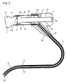
本実施態様において、この撓み動作伝動装置は、制御要素1と、幾つかのワイヤ体2と、ベース要素としてのロッド要素3と、ロッド要素ホルダ4と、カテーテルチューブ5と、撓み部分6としての曲げられる本体(曲げ可能な本体)とで構成される。
In this embodiment, the bending motion transmission device comprises a
制御要素1は、制御ヘッド12を備える円筒形要素で構成され、シャフト部分13が、その底側に中心的に配置される。シャフト部分13は、制御ヘッド12と反対側の端にフット部分11を有する。シャフト部分13は、一定の外径を有する。フット部分13は、制御ヘッド12と反対の方向において増大する外径を有する。
The
制御要素1は、フット部分11で、ロッド要素3に対して旋回する。従って、制御要素1のフット部分11を旋回部分11と呼ぶ。
The
旋回部分11は、制御ヘッド12と反対の側に、フット面11Aとして形成される端面を有する。本実施態様において、フット面11Aは、外向きに湾曲させられている。換言すれば、円筒形制御要素1の長手方向において測定される、フット面11Aとフットと反対側の制御ヘッド12の正面との間の距離は、外周から中央に向かって増大する。よって、フット面11Aは、所定の半径を備えるボール面を形成し、所定の半径の中心は、制御要素1の仮想の延長軸上に位置する。
The turning
制御要素1は、図1−4に見ることができるように、回転対称的である。制御要素1は、プラスチック材料で作製されるが、金属で作製されてもよい。
The
旋回部分11のフット面11Aは、図1−4に示すように、ロッド要素3のヘッド部分31の正面31Aに面する。
The
ロッド要素3は、長手シリンダ32を有し、長手シリンダ32は、その近位側で、ヘッド部分31になる。長手シリンダ32は、その遠位端部分に、本実施態様では内側正方形として設計されるネジ端34を更に有する。正方形端34に対して近位に、ロッド要素3は、その外側シリンダ面に、外ネジ山付き部分33を有する。ロッド要素3は、回転対称的に構成される。その上、ヘッド部分31、長手シリンダ32、及び正方形端34は、一体的なロッド要素として構成される。ロッド要素3の長手シリンダ32は、その上に設けられるネジ山付き部分33を除き、滑らかな外面を備えるシリンダとして形成される。
The
本実施態様では、正面31Aも制御要素1に向かって外向きに湾曲させられる。換言すれば、正面31Aは、制御要素1に向かう方向において、外周から中央に向かって上昇する。正面31Aは、所定の半径を備えるボール面の部分を形成し、所定の半径の中心は、ロッド要素3の仮想の延長軸上に位置する。
In this embodiment, the
フット面11A及び正面31Aは互いに面し合い、互いに接触し合う。故に、制御要素1の旋回部分11は、そのフット面11Aで、ロッド要素3のヘッド部分31の正面31Aに旋回的に位置付けられる。
The
非旋回状態において、制御要素1の旋回部分11及びロッド要素3のヘッド部分31は、同じ中心軸の上に位置する。何故ならば、制御要素1及びロッド要素3は、非旋回状態において互いに同軸に配置されるからである。故に、非旋回状態において、フット面11Aの中心及び正面31Aの中心は互いに触れ合う。制御要素1が旋回させられるとき、即ち、旋回部分11がロッド要素3のヘッド部分31に対して傾けられるとき、フット面11Aは、正面31A上で回転する。
In the non-turning state, the turning
よって、制御要素1は、ロッド要素3のヘッド部分31の上にジョイスティックのように位置付けられる。
The
図1−4に示すように、ロッド要素3は、ロッド要素ホルダ4内に配置される。ロッド要素ホルダ4は、回転対称的に構成されるシリンダ要素42として形成される。シリンダ要素42は、具体的には、制御要素1に向かって面する側にある中空の空間と、制御要素1から見て外方を向くロッド要素ホルダ4の側にある底とを有する。ロッド要素ホルダ4の底は、同心状の内側通路を有する。同心状の内側通路内には、内ネジ山41が、その一部に形成される。図1−4に概略的に示すように、ロッド要素3の外ネジ山33は、ロッド要素ホルダ4の内ネジ山41の上に位置付けられる。ネジ動作を用いて、ロッド要素3を、ロッド要素ホルダ4に対して内に又は外に同心状にネジ式に回し得る。ネジ動作をもたらす目的のために、適切な工具がロッド要素3の正方形端34内に挿入される。本記述の終わりの部分に「代替的な実施態様」の下に説明するように、他の相対的な移動技法も可能である。
As shown in FIGS. 1 to 4, the
ロッド要素ホルダ4のシリンダ要素42は、その外周側の一部にカテーテル接続要素43を有する。本実施態様において、カテーテル接続要素43は、図面から明らかになるように、ロッド要素4のシリンダ要素42に対して鋭角に延びる。
The
具体的には、カテーテル接続要素43は、シリンダ要素42の遠位中空空間からの通路分枝を基本的に構成する、丸い中空プロファイルとして設計されている。カテーテル接続要素43は円筒形に形成され、シリンダ要素42から離れる方向において先細る。カテーテル接続要素43は、内側に、ワイヤ体2を案内する同心状の通路を有する。カテーテル接続要素43は、その遠位端に、円形ポートを有する。
Specifically, the
カテーテルチューブ5は、カテーテル接続要素43の円形ポートに取り付けられる。具体的には、カテーテルチューブ5の近位端51が、カテーテル接続要素43のポートに位置付けられる。
The catheter tube 5 is attached to the circular port of the
その遠位端に、カテーテルチューブ5は、そこに組み込まれるリング52を有する。リング52は、カテーテルチューブ5の遠位端及び撓み部分6への移行部を形成する。
At its distal end, the catheter tube 5 has a
撓み部分6は、既知の方法において弾性材料で作製される曲げられる本体である。その近位端に、撓み部分6は、撓み接続部61を有し、撓み部分6は、撓み接続部61で、カテーテルチューブ5のリング52に接続される。撓み部分6は、遠位端に、撓みキャップ62を有し、撓みキャップ62には、カメラ、レーザ及び/又はカメラ等が配置される。更なる機能的ユニットを撓みキャップ62統合し得る。
The flexure 6 is a bent body made of an elastic material in a known manner. At its proximal end, the flexure 6 has a
図5に示すように、幾つかの吊下げキャビティ14(hang-in cavity)が、制御要素1の旋回部分11の外周面に設けられる。本実施態様では、4つの吊下げキャビティ14が、旋回部分11の外周面に設けられている。具体的には、吊下げキャビティ14は、旋回部分11の外周面に形成される凹部であり、円形断面及び底を有し、底は吊下げキャビティ14の延伸方向に対して略垂直に延びる。換言すれば、吊下げキャビティ14の底は、フット面11Aと反対の制御要素1の側に形成される制御ヘッド12の正面と略平行に延びる。
As shown in FIG. 5, several hang-in
吊下げキャビティ14を製造するときには、吊下げキャビティ14が旋回部分11の外周面にある横方向に開放する盲孔として形成されるよう、旋回部分11を切削し得る。任意の他の製造方法が可能である。吊下げキャビティ14の外径は、ワイヤ体2のバレルニップル21(barrel nipple)が吊下げキャビティ14内に適合するように選択される。吊下げキャビティ14の底、即ち、吊下げキャビティ14の遠位端には、通路15がワイヤ体吊下げ部(wire body hang-in)として形成され、通路15は、制御要素1の長手方向延伸と同軸に延び、ワイヤ体2の外径よりも大きいがワイヤ体2のバレルニップル21の外径よりも小さい直径を有する。換言すれば、吊下げキャビティ14及びワイヤ体吊下げ部15は、自転車でのボーデンケーブルの取付けと同様に、ワイヤ体2のバレルニップル21を吊下げキャビティ及びワイヤ体吊下げ部内に吊り下げ得るように設けられる。ワイヤ体2の吊下げ状態において、バレルニップル21は、ワイヤ体2の近位端を形成する。
When manufacturing the suspended
本実施態様では、4つのワイヤ体2が設けられ、それらのうちの2つ、即ち、ワイヤ体2a及びワイヤ体2bが、図1乃至4の各々に表されている。ワイヤ体の数は限定されない。1つの単一のワイヤ体2だけが設けられてよい。2つ、3つ、4つ又はそれよりも多くのワイヤ体が設けられてよい。2つ又はそれよりも多くのワイヤ体2が設けられるならば、対応する吊下げキャビティ14が、旋回部分11の外表面に互いに均等に離間して配置される。
In this embodiment, four
図4に示すように、シリンダ要素42は、その近位端に、即ち、制御要素1に面するその端に、中空空間へのアクセス開口を有する。近位面、即ち、制御要素1に面する、ワイヤ案内リング7の表面が、シリンダ要素42の近位正面、即ち、制御要素1と面する面と位置合わせされるよう、ワイヤ体案内リング7が、このアクセス開口内に挿入される。ワイヤ案内リング7は、図5に示すように、ワイヤ体2と同じ数の接線スリット74を備える。ワイヤ案内リング7の中心軸と同軸に延びるワイヤ案内開口71が、スリット74内に穿孔される。ついでながら、ワイヤ案内リング7の中心軸は、ロッド要素3及びロッド要素ホルダ4のシリンダ要素42のそれぞれの軸と同軸である。より具体的には、各吊下げキャビティ14から制御要素1の中心軸までの距離は、ワイヤ案内ボア71とワイヤ案内リング7の中心軸との間の径方向距離と全く同じである。各ワイヤ案内ボア71は、対応するワイヤ体吊下げ部15に中心化される。
As shown in FIG. 4, the
いずれの接線スリット74のスリット端73も、図5に示すように、平坦なワイヤ案内リング7の外周面に配置される。更に、平坦なワイヤ案内リング7の外周面は、固定ネジを収容するネジ山付き孔72を備え、ワイヤ案内リング7は、固定ネジを用いて、ロッド要素ホルダ4のシリンダ要素42に固定される。固定ネジのための1つのネジ山付き孔72のみを図5に示しているが、対応する数の複数の固定ネジのための複数のネジ山付き孔72もワイヤ案内リング7に設け得る。
The slit end 73 of any
ワイヤ体2は、カテーテルチューブ5を通じて並びにカテーテルチューブ5のリング52を通じて案内され、撓み部分6の撓みキャップ62で固着される。具体的には、ワイヤ体2は、それらが互いに均等に離間させられる並びに旋回部分11で配置されるのと同じ順序において配置されるような方法において、撓みキャップ62で固着される。
The
リング52は、ワイヤ案内リング7の設計に対応する方法において、ワイヤ体2のための開口を有する。
The
撓みキャップ62での固定地点から旋回部分11での固定地点までの各ワイヤ体2の長さは、常に同じである。
The length of each
(動作モード) (action mode)
制御要素1をジョイスティックのように作動させることができ、その旋回部分11をロッド要素3のヘッド部分31の上で回転式に移動させ得る。よって、旋回部分11がロッド要素3のヘッド部分31に対して傾けられるとき、フット面11Aは、正面31Aの上で回転する。それにより、旋回部分11に配置されるワイヤ体2の端は、ロッド要素3、ロッド要素ホルダ4、及びカテーテルチューブ5のアセンブリに対して、引っ張られ或いは押される。
The
それにより、あらゆる方向におけるロッド要素3に対するジョイスティック1の旋回操作が可能である。その場合、ロッド要素3に対するジョイスティック1の撓み動作の方向及び程度は、撓みキャップ62に配置されるワイヤ体2によって、曲げられる本体として設計される撓み部分6に伝えられる。
Thereby, the turning operation of the
換言すれば、図2に示すように、ジョイスティック1がロッド要素3に対して左に動かされると、右のワイヤ体2aが引っ張られ、それにより、撓み部分6において、右のワイヤ体2bが撓みキャップ62を近位方向に引っ張る。同時に、左のワイヤ体2bが押され、それにより、撓み部分6において、左のワイヤ体2bが撓みキャップ62を遠位方向に押す。よって、図2において、撓み部分6は、左に向けられた動作を行う。
In other words, as shown in FIG. 2, when the
ジョイスティック1がロッド要素3に対して右に動かされると、図3における場合のように、撓み部分6は、右に向けられた動作を行う。
When the
(第2の実施態様) (Second Embodiment)
引き続き、図6−9を用いて、本発明の第2の実施態様を詳細に記載する。 Subsequently, the second embodiment of the present invention will be described in detail with reference to FIGS.
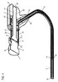
本実施態様においても、撓み動作伝動装置は、制御要素1と、幾つかのワイヤ体2と、ロッド要素3と、ロッド要素ホルダ4と、カテーテルチューブ5と、撓み部分6としての曲げられる本体(曲げ可能な本体)とで構成される。
Also in this embodiment, the bending motion transmission device comprises a
制御要素1は、制御ヘッド12を備える円筒形要素で構成され、制御ヘッド12の底側には、シャフト部分13が中心的に配置される。前の実施態様における以外、シャフト部分13は、中空ボール部分11’になり、その外面には、ワイヤ体2が固着される。中空ボール部分11’は、制御ヘッド12から見て外方を向く側で開放している。具体的には、中空ボール部分11’の開口は、例えば、中空ボール部分11’が、ボールの約9/10を構成するように設計され、約1/10がボールから切り落とされる。
The
制御要素1は、図6−8に示すように、回転対称である。制御要素1は、プラスチック材料で作製されるが、金属で作製されてもよい。
The
よって、制御要素1は、ロッド要素3のヘッド31の上にジョイスティックのように位置付けられる。具体的には、制御要素1の中空ボール部分11’は、対向ボール部分31’の上に位置付けられ、対向ボール部分31’は、この実施態様において、ロッド要素3のヘッドを形成する。対向ボール部分31’は、その上に位置付けられる中空ボール部分31’が滑らかに移動可能であるような大きさのボール形状を有するような方法において、形成される。対向ボール部分31’と中空ボール部分11’との間の寸法関係は、ロッド要素3に対する制御要素1の相対的な動作が操作者による如何なる大きな努力を伴わずに可能であるが、他方では、中空ボール部分11’が対向ボール部分31’の上に緩く位置付けられないような、性質を有する。
Thus, the
ロッド要素3は、長手シリンダ32を有し、長手シリンダ32は、その近位側で、対向ボール部分31’になり、その遠位端で、例えば、内側正方形として設計される、ネジ端34になる。正方形端34に対して遠位に、ロッド要素3は、その外側シリンダ面に外ネジ山付き部分33を有する。ロッド要素3は、回転対称的に構成される。対向ボール部分31’、長手シリンダ32、及び正方形端34は、一体的なロッド要素として構成される。ロッド要素3の長手シリンダ32は、その上に設けられるネジ山付き部分33を除き、滑らかな外面を備える、シリンダとして形成される。
The
図6−8に示すように、ロッド要素3は、ロッド要素ホルダ4内に位置付けられる。第1の実施態様におけると同様に、ロッド要素ホルダ4は、シリンダ要素42で構成され、シリンダ要素42は、回転対称的に構成され、中心内側通路を有する。シリンダ要素42は、制御要素1に向かって面する中空空間と、制御要素1から見て外方を向くロッド要素ホルダ4の側にある底とを有する。ロッド要素ホルダ4の底は、同心状の内側通路を有する。内ネジ山41が同心状の内側通路内に設けられる。図面に概略的に示すように、ロッド要素3の外ネジ山33は、ロッド要素ホルダ4の内ネジ山41の上に位置付けられ、ネジ動作を用いて、ロッド要素3をロッド要素ホルダ4に対して内に又は外に同心状にネジ式に回し得る。ネジ動作をもたらす目的のために、適切な工具がロッド要素3の正方形端34内に挿入される。
As shown in FIGS. 6-8, the
ロッド要素ホルダ4のシリンダ要素42は、その外周面に、カテーテル接続要素43を有する。本実施態様においても、図面から明らかになるように、カテーテル接続要素43は、ロッド要素4のシリンダ要素42に対して鋭角に延びる。
The
カテーテル接続要素43は、シリンダ要素42の遠位中空空間からの通路分枝を形成する、丸い中空プロファイルとして設計される。カテーテル接続要素43は円筒形に形成され、シリンダ要素42から見て外方を向く方向に先細る。カテーテル接続要素43は、内側に、ワイヤ体2を案内するための同心状の通路を有する。カテーテル接続要素43は、その遠位端に、円形ポートを有する。
The
カテーテルチューブ5は、カテーテル接続要素43の円形ポートに取り付けられる。具体的には、カテーテルチューブ5の近位端51は、カテーテル接続要素43のポートに位置付けられる。その遠位端に、カテーテルチューブ5は、その中に収容されるリング52を有する。リング52は、カテーテルチューブ5の遠位端及び撓み部分6への移行部を形成する。
The catheter tube 5 is attached to the circular port of the
撓み部分6は、既知の方法においてプラスチック材料で作製される、曲げられる本体である。撓み部分6は、その近位端に、撓み接続部61を有し、撓み部分6は、撓み接続部61で、カテーテルチューブ5のリング52に接続される。撓み部分6は、遠位端に、撓みキャップ62を有し、撓みキャップ62には、カメラ、レーザ及び/又はカメラ等が配置される。更なる機能的ユニットを撓みキャップ62に統合し得る。
The flexure 6 is a bent body that is made of a plastic material in a known manner. The flexible portion 6 has a
図9は、第2の実施態様の制御要素に対するワイヤ体の接続の詳細及びワイヤ体がカテーテルチューブにどのように案内されるかを概略的な部分斜視図において示している。より良好な明確性のために、正面左のワイヤ体2は、この図面において示されていない。
FIG. 9 shows in a schematic partial perspective view the details of the connection of the wire body to the control element of the second embodiment and how the wire body is guided into the catheter tube. For better clarity, the front
図9に示すように、幾つかの吊下げキャビティ14が、中空ボール部分11’の赤道線(equatorial line)上で、中空ボール部分11’の外周面に設けられる。本実施態様では、4つの吊下げキャビティ14が、中空ボール部分11’の赤道(equator)上に設けられる。具体的には、吊下げキャビティ14は、中空ボール部分11’に形成される凹部であり、吊下げキャビティ14は、円形断面及び底を有し、底は吊下げキャビティ14の延伸方向に対して略垂直に延び、赤道線に、より具体的には、中空ボール部分11’の赤道に対して垂直に配置される。吊下げキャビティ14を製造するときには、吊下げキャビティ14が中空ボール部分11’の外表面にある横方向に開放する盲孔として形成されるよう、例えば、研削によって、中空ボール部分11’を近位側から製造し得る。任意の他の製造方法が可能である。吊下げキャビティ14の外径は、ワイヤ体2のバレルニップル21が吊下げキャビティ14内に適合するように選択される。吊下げキャビティ14の底で、即ち、吊下げキャビティ14の遠位端で、通路がワイヤ体吊下げ部として設計され、通路は、制御要素1の長手方向延伸と同軸に延び、ワイヤ体2の外径よりも大きいがワイヤ体2のバレルニップル21の外径よりも小さい直径を有する。換言すれば、吊下げキャビティ14及びワイヤ体吊下げ部15は、第1の実施態様における吊下げキャビティ及びワイヤ体吊下げ部と類似する。
As shown in FIG. 9, several hanging
ここでも、ワイヤ体2の数は限定されない。2つ又はそれよりも多くのワイヤ体2が設けられるならば、対応する吊下げキャビティ14が、互いに均等に離間させられて中空ボール部分11’の赤道に配置される。
Again, the number of
第1の実施態様におけると同様に、図9に示すように、ワイヤガイド2と同じ数の接線スリット74を有するワイヤ体案内リング7が設けられる。ロッド要素3及びロッド要素ホルダ4のシリンダ要素42の共通軸と同軸に延びるワイヤ案内開口71が、スリット74内に穿孔される。
As in the first embodiment, as shown in FIG. 9, a wire
各接線スリット74のスリット端73は、図9に示すように、平坦なワイヤ案内リング7の外周面に配置される。第1の実施態様におけると同様に、平坦なワイヤ案内リング7の外周面は、固定ネジを収容するネジ山付き孔72を備え、ワイヤ案内リング7は、固定ネジを用いて、ロッド要素ホルダ4のシリンダ要素42に固定される。固定ネジのための1つのネジ山付き孔72のみを図9に示しているが、対応する数の複数の固定ネジのための複数のネジ山付き孔72もワイヤ案内リング7に設け得る。
As shown in FIG. 9, the slit end 73 of each
この場合においても、ワイヤ体2は、カテーテルチューブ5を通じて並びにカテーテルチューブのリング52を通じて案内され、撓み部分6の撓みキャップ62で固着される。ワイヤ体2は、それらが互いに均等に離間させられる並びに中空ボール部分11’上と同じ順序において取り付けられる方法において、撓みキャップ62で固着される。リング52は、ワイヤ案内リング7の設計と対応する方法においてワイヤ体2のための開口を有する。
In this case as well, the
(動作モード) (action mode)
第1の実施態様におけると同様に、制御要素1をジョイスティックのように操作し得る。この実施態様では、中空ボール部分11’をロッド要素3の対向ボール部分31’の上に移動させ得る。それにより、あらゆる方向におけるロッド要素3に対するジョイスティック1の旋回操作が可能である。その場合、ロッド要素3に対するジョイスティック1の撓み動作の方向及び程度は、撓みキャップ62の上に配置されるワイヤ体2によって、曲げられる本体として設計される撓み部分6に伝えられる。換言すれば、ジョイスティック1がロッド要素3に対して左に動かされると、撓み部分は、図7に示すように、左に向けられる動作を行う。ジョイスティック1がロッド要素3に対して右に動かされると、撓み部分は、図8に示すように、右に向けられる動作を行う。
As in the first embodiment, the
(代替的な実施態様) (Alternative embodiment)
ワイヤ体2は、吊下げキャビティ14内に吊り下げられ、それはバレルニップル21の形態において図4に示されている。本発明はバレルニップルに限定されない。ニップル21を既知の西洋ナシニップル(pear nipple)として設計し得るし、任意の類似のニップルを用い得る。吊下げキャビティ14の形状を選択されるニップル形状に適合させ得る。
The
第1の実施態様において、フット面11Aは、外向きに湾曲させられる。更に、ヘッド部分31の正面31Aは、外向きに湾曲させられる。本発明はそれに限定されない。本発明の原理を用いることによって、フット面11Aが平面的に設計され、正面31Aが外向きに湾曲させられるよう、撓み動作伝動装置を構成することもできる。他方、フット面11Aが外向きに湾曲させられ、正面31Aが平面的に設計されるよう、撓み動作伝動装置を構成することもできる。正面31Aの曲率半径がフット面11Aの曲率半径よりも大きい限り、フット面31Aが内向きに湾曲させられ且つフット面11Aが外向きに湾曲させられる構造も可能である。同様に、正面31Aの曲率半径がフット面11Aの曲率半径よりも小さい限り、正面31Aを外向きに湾曲させ得るし、フット面11Aを内向きに湾曲させ得る。フット面11Aが正面31Aの上で安全に且つ制御された方法において回転し得ることだけで十分である。
In the first embodiment, the
第2の実施態様において、中空ボール部分11’の大きさは、それがボールの9/10を構成するように選択される。本発明はそれに限定されない。中空ボール部分11’が対向ボール部分31’の上で旋回動作を依然として行う限り、あらゆる中空ボールの大きさの中空ボール部分11’を選択し得る。中空ボール部分11’は、制御要素1の軸方向と平行に所定の最小の量だけ赤道線の両側に延びる並びに赤道帯(equatorial band)を基本的に形成する、中空ボールリング部分の形状も有し得る。
In the second embodiment, the size of the hollow ball portion 11 'is selected so that it constitutes 9/10 of the ball. The present invention is not limited to this. As long as the hollow ball portion 11 'is still pivoting on the opposing ball portion 31', a hollow ball portion 11 'of any hollow ball size can be selected. The
正方形端34は、ネジ山付き部分33及び41でロッド要素ホルダ4に対するロッド要素3の相対的な動作を行うために、ネジ動作を可能にする働きをする。本発明はロッド要素3の端34での正方形の形状に限定されない。三角形、八角形、又は他の多角形も選択し得る。基本的には、端34でロッド要素の回転運動を生成するトルクの適用を可能にするあらゆる形状を選択し得る。
The
実施態様において、ロッド要素ホルダ4に対するロッド要素3の相対的な動作は、ネジ山付き部分33及び41によってもたらされる。ロッド要素ホルダ4に対するロッド要素3の移動によって、ワイヤ体2に張力がかけられる。この目的のために、ロッド要素ホルダ4に対するロッド要素3の移動の任意の他の方法を選択し得る。例えば、ロッド要素ホルダ4は連続的な内側シリンダ孔を有することができ、ロッド要素3は連続的な円筒形の長手シリンダ32を有することができ、引張装置がロッド要素3の端34に取り付けられる。ロッド要素ホルダ4内には、ロッド要素ホルダの軸に対して垂直にネジ山付き孔を設け得る。長手シリンダ32をロッド要素ホルダに対するあらゆる位置において係止(ロック)するように構成される係止ネジが、ネジ山付き孔内に位置付けられる。
In an embodiment, the relative movement of the
実施態様において、カテーテル接続要素43は、図1の考慮の下で、ロッド要素ホルダ4に対して鋭角に延びる。本発明はそれに限定されない。ロッド要素ホルダ4に対するカテーテル接続要素43のあらゆる延伸角(extension angle)を選択し得る。
In an embodiment, the
実施態様において、カテーテルチューブ5は、中空空間を有する伝動案内体(transmission guiding body)であり、動作伝動ワイヤ体(movement transmission wire body)は、中空空間内で案内される。制御要素の旋回動作中、動作伝動ワイヤ体2は、引張力及び押力に晒される。これらの引張力及び押力がそれらに対して加えられるとき、動作伝動ワイヤ体2は、伝動案内体の上で滑動するように構成されなければならない。伝動案内体は、カテーテルチューブ5の場合におけるように、閉塞断面を有し得る。本発明はそれに限定されない。伝動案内体は、動作伝動ワイヤ体をその上で案内するレール要素又はボックス要素であり得る。伝動案内体の断面は、動作伝動ワイヤ体2がその上で滑動しない側で開放し得る。
In an embodiment, the catheter tube 5 is a transmission guiding body having a hollow space, and the movement transmission wire body is guided in the hollow space. During the turning motion of the control element, the motion
制御要素1は、制御要素1の撓み位置を係止するために、係止可能であり得る。第2の実施態様において、係止は、係止ネジによって行われ、係止ネジは、例えば、中空ボール部分11’を貫通して対向ボール部分31’の表面と係合し、よって、係止ネジは、制御要素1の、故に、制御レバーの特定の撓み位置が、摩擦ブレーキによって係止可能であるような方法において、摩擦ブレーキとして作用する。その上、係止は、例えば、ワイヤ案内リング7で或いはロッド要素ホルダ4のシリンダ要素42で動作伝動ワイヤ体/複数の動作伝動ワイヤ体2を締め付けることによって、全ての実施態様において行われ得る。全てのワイヤ2が、例えば、ワイヤ案内リング7又はシリンダ要素42に取り付けられる係止クランプによって、係止される場合には、制御要素1の撓み位置の安全な係止が、それにより達成される。ワイヤ2を遮断する他の技術的可能性を選択し得る。
The
実施態様において、撓み動作伝動装置は、内視鏡内の内視鏡撓み制御に適用される。撓み動作伝動装置は、他の技術分野においても適用され得る。導水通路、採鉱トンネル等における使用が可能である。本発明は、旋回動作が撓み要素の撓み動作に変換される至る所で適用され得る。 In the embodiment, the bending motion transmission device is applied to endoscope deflection control in an endoscope. The bending motion transmission device can also be applied in other technical fields. It can be used in water conveyance passages and mining tunnels. The invention can be applied everywhere the turning movement is converted into the bending movement of the bending element.
1 制御要素;ジョイスティック
2 ワイヤ体
2a ワイヤ体
2b ワイヤ体
3 ベース要素;ロッド要素
4 ロッド要素ホルダ
5 カテーテルチューブ
6 曲げられる本体;撓み部分
7 ワイヤ案内リング
11 旋回部分
11A 旋回部分11のフット面
11’ 中空ボール部分
12 制御要素1のヘッド
13 シャフト部分
14 吊下げキャビティ
15 ワイヤ体吊下げ部
21 バレルニップル
31 ヘッド部分
31A ヘッド部分31の正面
32 長手シリンダ
33 ロッド要素3のネジ山付き部分
34 正方形端;ロッド要素3の遠位端
41 ロッド要素ホルダ4のネジ山付き部分
42 シリンダ要素
43 カテーテル接続要素
51 カテーテルチューブ接続部
52 リング
61 撓み接続部
62 撓みキャップ
71 ワイヤ案内ボア
72 固定ネジのためのネジ山付き孔
73 スリット入口
74 接線スリット
DESCRIPTION OF
Claims (11)
該制御要素の前記旋回部分に連結される少なくとも1つの動作伝動ワイヤ体と、
細長い伝動案内体であって、その長手方向において前記動作伝動ワイヤ体を案内する、伝動案内体と、
前記制御要素と反対の前記伝動案内体の端に位置付けられる、撓まされるべき曲げられる本体とを含み、前記動作伝動ワイヤ体は、前記伝動案内体への接続部から離間する方法において、前記制御要素に取り付けられ、
前記制御要素は、作動レバーとして構成され、該作動レバーは、前記旋回部分に、前記ベース要素に面するフット面を有し、
前記ベース要素の前記ヘッド部分は、前記制御要素に面する正面を有し、
前記制御要素の前記旋回部分の前記フット面及び前記ベース要素の前記ヘッド部分の前記正面は、前記フット面及び前記正面を互いに回転させ得るよう、互いに向かってそれぞれ湾曲させられ、
前記制御要素の前記旋回部分は、その外側に、前記動作伝動ワイヤ体の連結地点を有し、そのフット面で、前記ベース要素の前記ヘッド部分の前記正面の上に旋回的に位置付けられる、
撓み動作伝動装置。 A control element that provides a flexing motion, the control element having a pivoting portion that is supported by the head portion of the base element and that is pivotable relative to the head portion of the base element to effect the flexing motion;
At least one motion transmission wire body coupled to the swivel portion of the control element;
An elongate transmission guide body, which guides the operation transmission wire body in its longitudinal direction;
In a method wherein the motion transmission wire body is spaced from a connection to the transmission guide body, the body being bent and positioned at the end of the transmission guide body opposite the control element. Attached to the element,
The control element is configured as an actuating lever, the actuating lever having a foot surface facing the base element at the pivot part;
The head portion of the base element has a front face facing the control element;
The front surface of the swivel portion of the control element and the front surface of the head portion of the base element are respectively curved toward each other so that the foot surface and the front surface can rotate relative to each other;
The swivel portion of the control element has a connection point of the motion transmission wire body on its outer side and is pivotally positioned on the foot surface over the front of the head portion of the base element;
Bending motion transmission device.
前記伝動案内体は、カテーテルチューブであり、前記撓まされるべき本体は、曲げ部分である、
内視鏡曲げコントローラ。 An endoscope bending controller including the bending motion transmission device according to any one of claims 1 to 9,
The transmission guide is a catheter tube, and the body to be bent is a bent portion.
Endoscopic bending controller.
内視鏡。 The endoscope bending controller according to claim 10 is provided.
Endoscope.
Applications Claiming Priority (3)
| Application Number | Priority Date | Filing Date | Title |
|---|---|---|---|
| DE201310222041 DE102013222041A1 (en) | 2013-10-30 | 2013-10-30 | Deflection movement transmission device, endoscope deflecting control and endoscope |
| DE102013222041.3 | 2013-10-30 | ||
| PCT/EP2014/073065 WO2015063052A1 (en) | 2013-10-30 | 2014-10-28 | Deflection movement transmission device, endoscope bend control, and endoscope |
Publications (2)
| Publication Number | Publication Date |
|---|---|
| JP2017500902A true JP2017500902A (en) | 2017-01-12 |
| JP6389882B2 JP6389882B2 (en) | 2018-09-12 |
Family
ID=51842517
Family Applications (1)
| Application Number | Title | Priority Date | Filing Date |
|---|---|---|---|
| JP2016525518A Active JP6389882B2 (en) | 2013-10-30 | 2014-10-28 | Bending motion transmission device, endoscope bending controller, and endoscope |
Country Status (6)
| Country | Link |
|---|---|
| US (1) | US10092171B2 (en) |
| EP (1) | EP3062680B1 (en) |
| JP (1) | JP6389882B2 (en) |
| DE (1) | DE102013222041A1 (en) |
| ES (1) | ES2666996T3 (en) |
| WO (1) | WO2015063052A1 (en) |
Families Citing this family (6)
| Publication number | Priority date | Publication date | Assignee | Title |
|---|---|---|---|---|
| DE102015109170B4 (en) * | 2015-06-10 | 2019-08-22 | Digital Endoscopy Gmbh | Deflection movement transmission device, Endoskopbiegesteuereinrichtung and endoscope |
| DE102016105767B4 (en) | 2016-03-30 | 2020-10-01 | Digital Endoscopy Gmbh | Endoscope control device and endoscope |
| DE102018209087A1 (en) * | 2018-06-07 | 2019-12-12 | Epflex Feinwerktechnik Gmbh | Control handle device and catheter instrument |
| NL2022893B1 (en) * | 2019-04-08 | 2020-10-15 | Fortimedix Assets Ii B V | Steerable instrument comprising a detachable part |
| US20220167836A1 (en) * | 2019-04-08 | 2022-06-02 | Fortimedix Assets Ii B.V. | Steerable instrument comprising a detachable part |
| US20220233205A1 (en) * | 2021-01-26 | 2022-07-28 | Olympus America Inc. | Sheath for catheter length adjustment |
Citations (5)
| Publication number | Priority date | Publication date | Assignee | Title |
|---|---|---|---|---|
| JP2007252921A (en) * | 2006-03-23 | 2007-10-04 | Ethicon Endo Surgery Inc | Endoscope accessory channel subjected to articular movement |
| US20070250110A1 (en) * | 2006-04-24 | 2007-10-25 | Mattel, Inc. | Medical instrument handle and medical instrument having a handle |
| JP2009101134A (en) * | 2007-08-23 | 2009-05-14 | Tyco Healthcare Group Lp | Endoscopic surgical device |
| JP2009530051A (en) * | 2006-03-23 | 2009-08-27 | ボストン サイエンティフィック リミテッド | Medical devices and systems |
| JP2012245058A (en) * | 2011-05-25 | 2012-12-13 | Olympus Corp | Endoscope apparatus |
Family Cites Families (77)
| Publication number | Priority date | Publication date | Assignee | Title |
|---|---|---|---|---|
| JPS4827116Y1 (en) | 1967-04-21 | 1973-08-09 | ||
| US3549806A (en) | 1967-05-05 | 1970-12-22 | Gen Electric | Fundamental pitch frequency signal extraction system for complex signals |
| US3605725A (en) | 1968-08-07 | 1971-09-20 | Medi Tech Inc | Controlled motion devices |
| DE6905185U (en) | 1969-02-11 | 1972-04-06 | Bowden Controls Ltd | BOWDEN TRAIN. |
| JPS6121041Y2 (en) | 1977-08-04 | 1986-06-24 | ||
| JPS5939128B2 (en) | 1979-10-31 | 1984-09-21 | オリンパス光学工業株式会社 | Endoscope |
| JPS57110228A (en) | 1980-12-26 | 1982-07-09 | Olympus Optical Co | Air and water sending switch apparatus of endoscope |
| US4415767A (en) | 1981-10-19 | 1983-11-15 | Votan | Method and apparatus for speech recognition and reproduction |
| JPS60148536A (en) | 1984-01-17 | 1985-08-05 | オリンパス光学工業株式会社 | Endoscope |
| JPS61118713A (en) | 1984-11-14 | 1986-06-06 | Olympus Optical Co Ltd | Endoscope |
| US4670009A (en) | 1985-04-16 | 1987-06-02 | American Hospital Supply Corp. | Backform inserts for catheter |
| JPS62227312A (en) | 1986-03-27 | 1987-10-06 | 旭光学工業株式会社 | Mount structure of curving operation wire of endoscope |
| US5245133A (en) | 1991-10-15 | 1993-09-14 | Thomas & Betts Corporation | Moisture-resistant cable splice and sealing structure thereof |
| JP3219521B2 (en) | 1993-03-01 | 2001-10-15 | オリンパス光学工業株式会社 | Endoscope |
| US5569157A (en) | 1993-05-07 | 1996-10-29 | Olympus Optical Co., Ltd. | Endoscope |
| US5588950A (en) | 1994-07-11 | 1996-12-31 | Asahi Kogaku Kogyo Kabushiki Kaisha | Portable endoscope system |
| US5630419A (en) | 1994-12-20 | 1997-05-20 | Tetrad Corporation | Sealing connector for multiconductor cables |
| DE19627016C1 (en) | 1996-07-04 | 1998-02-12 | Etm Endotech Gmbh Medizintechn | Flexible endoscope |
| US5845241A (en) | 1996-09-04 | 1998-12-01 | Hughes Electronics Corporation | High-accuracy, low-distortion time-frequency analysis of signals using rotated-window spectrograms |
| JPH10225439A (en) | 1997-02-17 | 1998-08-25 | Olympus Optical Co Ltd | Image pickup device for endoscope |
| US5876332A (en) | 1997-07-24 | 1999-03-02 | Genzyme Corporation | Surgical support member |
| DE19731965A1 (en) | 1997-07-24 | 1999-01-28 | Etm Endotech Gmbh Medizintechn | Air / water and suction valves on endoscopes |
| DE19840986A1 (en) | 1998-09-08 | 2000-03-09 | Etm Endoskopische Technik Gmbh | Quick release for an endoscope |
| DE19843337A1 (en) | 1998-09-22 | 2000-03-23 | Sram De Gmbh | Cable control adjustment mechanism for bicycle has fewer components than prior art and retains lubricating grease |
| US6734893B1 (en) | 1998-12-04 | 2004-05-11 | Olympus Winter & Ibe Gmbh | Endoscopy illumination system for stroboscopy |
| JP3179426B2 (en) | 1998-12-21 | 2001-06-25 | オリンパス光学工業株式会社 | Endoscope device |
| US6547722B1 (en) | 1999-07-13 | 2003-04-15 | Olympus Optical Co., Ltd. | Endoscope having resistance to high-temperature and high-pressure steam |
| JP2001061772A (en) | 1999-08-30 | 2001-03-13 | Fuji Photo Optical Co Ltd | Fluid controller for endoscope |
| JP3488170B2 (en) | 2000-03-21 | 2004-01-19 | オリンパス株式会社 | Endoscope |
| JP3821206B2 (en) | 2000-09-29 | 2006-09-13 | フジノン株式会社 | Waterproof cap for connector of endoscope |
| JP2002160691A (en) | 2000-11-28 | 2002-06-04 | Nissin Kogyo Co Ltd | Brake device for bar handle vehicle |
| JP2002238831A (en) | 2001-02-16 | 2002-08-27 | Fuji Photo Optical Co Ltd | Endoscope |
| JP2002291699A (en) | 2001-03-30 | 2002-10-08 | Asahi Optical Co Ltd | Endoscope system for vocal cords observation |
| US20060199999A1 (en) | 2001-06-29 | 2006-09-07 | Intuitive Surgical Inc. | Cardiac tissue ablation instrument with flexible wrist |
| US6793622B2 (en) | 2001-09-05 | 2004-09-21 | Olympus Optical Co., Ltd. | Electric bending endoscope |
| JP2003190085A (en) | 2001-12-25 | 2003-07-08 | Olympus Optical Co Ltd | Electrical connector |
| JP2007111541A (en) | 2002-05-29 | 2007-05-10 | Olympus Corp | Endoscope apparatus and connecting device for endoscope |
| JP2004049891A (en) | 2002-05-29 | 2004-02-19 | Olympus Corp | Endoscope apparatus |
| US7179223B2 (en) | 2002-08-06 | 2007-02-20 | Olympus Optical Co., Ltd. | Endoscope apparatus having an internal channel |
| DE10320228A1 (en) | 2003-05-05 | 2004-11-25 | Stm Medizintechnik Starnberg Gmbh | endoscope shaft |
| US7842028B2 (en) * | 2005-04-14 | 2010-11-30 | Cambridge Endoscopic Devices, Inc. | Surgical instrument guide device |
| CN100446712C (en) | 2004-02-16 | 2008-12-31 | 奥林巴斯株式会社 | Endoscope system |
| AU2005228956B2 (en) | 2004-03-23 | 2011-08-18 | Boston Scientific Limited | In-vivo visualization system |
| JP2005304586A (en) | 2004-04-19 | 2005-11-04 | Pentax Corp | Distal end portion of side viewing type endoscope |
| JP4661190B2 (en) | 2004-11-30 | 2011-03-30 | 富士フイルム株式会社 | Cleaning adapter |
| CN2762381Y (en) | 2004-12-17 | 2006-03-01 | 亮泰企业股份有限公司 | Water-proof structure of DC power supply plug and socket |
| WO2006126265A1 (en) * | 2005-05-26 | 2006-11-30 | Ars Co., Ltd. | Endoscope device |
| CN101282676B (en) | 2005-06-24 | 2011-05-18 | 通用检查技术公司 | Insertion tube storage carousel |
| DE102005041454A1 (en) | 2005-08-31 | 2007-03-01 | Karl Storz Gmbh & Co. Kg | Endoscope, has bowden cable that is mounted proximal-laterally by clamping grippers, where plug-in depth of towing cable of bowden cable is limited in clamping grippers by pressing unit, which acts on towing cable and clamping grippers |
| US20070225562A1 (en) * | 2006-03-23 | 2007-09-27 | Ethicon Endo-Surgery, Inc. | Articulating endoscopic accessory channel |
| JP4812515B2 (en) | 2006-05-26 | 2011-11-09 | 富士フイルム株式会社 | Cleaning adapter |
| US7615067B2 (en) | 2006-06-05 | 2009-11-10 | Cambridge Endoscopic Devices, Inc. | Surgical instrument |
| JP2008119057A (en) | 2006-11-08 | 2008-05-29 | Matsushita Electric Works Ltd | Capsule-type imaging device |
| US8409245B2 (en) * | 2007-05-22 | 2013-04-02 | Woojin Lee | Surgical instrument |
| KR200444134Y1 (en) | 2007-07-09 | 2009-04-10 | 유메디칼 주식회사 | Laryngeal Stroboscope Using Voice Signal |
| ES2356497T3 (en) | 2007-08-23 | 2011-04-08 | Tyco Healthcare Group Lp | ENDOSCOPIC SURGICAL DEVICES. |
| JP2009201762A (en) | 2008-02-28 | 2009-09-10 | Hoya Corp | Endoscope and photographing module |
| ATE516736T1 (en) | 2008-05-16 | 2011-08-15 | Fujifilm Corp | CONNECTOR FOR ENDOSCOPE |
| RU2510234C2 (en) | 2008-12-10 | 2014-03-27 | Амбу А/С | Endoscope having camera enclosure, and method for making camera enclosure |
| US8700129B2 (en) | 2008-12-31 | 2014-04-15 | St. Jude Medical, Atrial Fibrillation Division, Inc. | Devices and methods for catheter localization |
| DE102009060500B4 (en) | 2009-12-22 | 2015-12-17 | Xion Gmbh | A method for stroboscopically examining repetitive processes and arrangement for operating this method |
| WO2011108157A1 (en) | 2010-03-05 | 2011-09-09 | オリンパスメディカルシステムズ株式会社 | Endoscope |
| CN102791182A (en) | 2010-03-16 | 2012-11-21 | 奥林巴斯医疗株式会社 | Connector receiver, connector connection system, light source device, and endoscope |
| TW201201641A (en) | 2010-06-18 | 2012-01-01 | Sun Wei Ren | Micro sensor |
| DE102010034623A1 (en) | 2010-08-17 | 2012-02-23 | Olympus Winter & Ibe Gmbh | Generic endoscope used for e.g. laparoscopic surgery, has video camera, electrical conductors and contact device that are enclosed in cast structure of main portion |
| DE102010039731A1 (en) | 2010-08-25 | 2012-03-01 | Olympus Winter & Ibe Gmbh | Electrical connector and endoscopy system |
| JP5552014B2 (en) | 2010-09-29 | 2014-07-16 | 富士フイルム株式会社 | Endoscope suction button |
| JP4897117B1 (en) | 2010-12-24 | 2012-03-14 | オリンパス株式会社 | Endoscope device |
| EP2659656B1 (en) | 2010-12-29 | 2018-07-18 | Skype | Dynamical adaptation of data encoding dependent on cpu load |
| WO2013018896A1 (en) | 2011-08-03 | 2013-02-07 | オリンパス株式会社 | Wire-pulling mechanism and endoscopic apparatus |
| CN102401995B (en) | 2011-11-18 | 2013-05-29 | 无锡微奥科技有限公司 | Micro optical probe of endoscope |
| JP5883683B2 (en) | 2012-03-02 | 2016-03-15 | Hoya株式会社 | Optical scanning endoscope |
| DE102012009332B4 (en) | 2012-05-10 | 2019-02-21 | Karl Storz Se & Co. Kg | endoscope |
| CN202748535U (en) | 2012-08-16 | 2013-02-20 | 宁波舜宇光电信息有限公司 | Industrial endoscope |
| WO2014038638A1 (en) | 2012-09-05 | 2014-03-13 | オリンパスメディカルシステムズ株式会社 | Ultrasonic endoscope |
| CN103211566B (en) | 2013-04-17 | 2014-12-10 | 杭州安杰思医学科技有限公司 | Endoscope with water injection and gas injection selecting button |
| EP3035836B1 (en) | 2013-08-20 | 2020-09-30 | Cook Medical Technologies LLC | Endoscope mountable visualization device and handle |
-
2013
- 2013-10-30 DE DE201310222041 patent/DE102013222041A1/en not_active Withdrawn
-
2014
- 2014-10-28 JP JP2016525518A patent/JP6389882B2/en active Active
- 2014-10-28 ES ES14790580.6T patent/ES2666996T3/en active Active
- 2014-10-28 EP EP14790580.6A patent/EP3062680B1/en active Active
- 2014-10-28 WO PCT/EP2014/073065 patent/WO2015063052A1/en active Application Filing
- 2014-10-28 US US15/033,074 patent/US10092171B2/en active Active
Patent Citations (5)
| Publication number | Priority date | Publication date | Assignee | Title |
|---|---|---|---|---|
| JP2007252921A (en) * | 2006-03-23 | 2007-10-04 | Ethicon Endo Surgery Inc | Endoscope accessory channel subjected to articular movement |
| JP2009530051A (en) * | 2006-03-23 | 2009-08-27 | ボストン サイエンティフィック リミテッド | Medical devices and systems |
| US20070250110A1 (en) * | 2006-04-24 | 2007-10-25 | Mattel, Inc. | Medical instrument handle and medical instrument having a handle |
| JP2009101134A (en) * | 2007-08-23 | 2009-05-14 | Tyco Healthcare Group Lp | Endoscopic surgical device |
| JP2012245058A (en) * | 2011-05-25 | 2012-12-13 | Olympus Corp | Endoscope apparatus |
Also Published As
| Publication number | Publication date |
|---|---|
| DE102013222041A1 (en) | 2015-04-30 |
| JP6389882B2 (en) | 2018-09-12 |
| EP3062680A1 (en) | 2016-09-07 |
| US10092171B2 (en) | 2018-10-09 |
| ES2666996T3 (en) | 2018-05-09 |
| WO2015063052A1 (en) | 2015-05-07 |
| US20160278616A1 (en) | 2016-09-29 |
| EP3062680B1 (en) | 2018-03-07 |
Similar Documents
| Publication | Publication Date | Title |
|---|---|---|
| JP6389882B2 (en) | Bending motion transmission device, endoscope bending controller, and endoscope | |
| JP7098556B2 (en) | Subendoscope that can be attached to the mother's endoscope and the combination of the mother's endoscope and the subendoscope | |
| JP6321159B2 (en) | Bending motion transmission device, endoscope bending controller, and endoscope | |
| US9687303B2 (en) | Dexterous wrists for surgical intervention | |
| JP5253689B1 (en) | Insertion equipment | |
| RU2517603C2 (en) | Mechanism of controlling bending part of endoscope | |
| EP2869750B1 (en) | Sinus endoscope | |
| US20150127045A1 (en) | Endoscopic instrument | |
| CN107949308B (en) | Deflecting motion transmission device, endoscope bending control device, and endoscope | |
| WO2015174304A1 (en) | Adapter for treatment instrument, endoscope, and endoscope system | |
| US20150366573A1 (en) | Instrument, in particular medical-endoscopic instrument or technoscope | |
| US20190329004A1 (en) | Flexible catheter using wires | |
| BR102018067342B1 (en) | probe applicator | |
| US20220233054A1 (en) | Endoscope with an articulated bending section body | |
| WO2016067436A1 (en) | Medical treatment tool | |
| US20230001150A1 (en) | Medical Apparatus System | |
| KR101759671B1 (en) | Apparatus For Controlling Endoscope | |
| CN212490143U (en) | Surgical instrument for minimally invasive surgery robot | |
| CN114098972A (en) | Surgical instrument for minimally invasive surgery robot | |
| US20120197075A1 (en) | Endoscope securement device and method of use | |
| CN110123246A (en) | Endoscope | |
| US11497386B2 (en) | Control element for an endoscopic apparatus, and endoscopic apparatus comprising a control element of this kind | |
| JP2014064798A (en) | Ultrasonic probe | |
| KR20170074118A (en) | endoscope probe, handpiece for controlling Endoscope, Apparatus for Controlling Endoscope |
Legal Events
| Date | Code | Title | Description |
|---|---|---|---|
| A621 | Written request for application examination |
Free format text: JAPANESE INTERMEDIATE CODE: A621 Effective date: 20161215 |
|
| A977 | Report on retrieval |
Free format text: JAPANESE INTERMEDIATE CODE: A971007 Effective date: 20170810 |
|
| A131 | Notification of reasons for refusal |
Free format text: JAPANESE INTERMEDIATE CODE: A131 Effective date: 20170905 |
|
| A601 | Written request for extension of time |
Free format text: JAPANESE INTERMEDIATE CODE: A601 Effective date: 20171204 |
|
| A521 | Request for written amendment filed |
Free format text: JAPANESE INTERMEDIATE CODE: A523 Effective date: 20180301 |
|
| TRDD | Decision of grant or rejection written | ||
| A01 | Written decision to grant a patent or to grant a registration (utility model) |
Free format text: JAPANESE INTERMEDIATE CODE: A01 Effective date: 20180724 |
|
| A61 | First payment of annual fees (during grant procedure) |
Free format text: JAPANESE INTERMEDIATE CODE: A61 Effective date: 20180820 |
|
| R150 | Certificate of patent or registration of utility model |
Ref document number: 6389882 Country of ref document: JP Free format text: JAPANESE INTERMEDIATE CODE: R150 |
|
| R250 | Receipt of annual fees |
Free format text: JAPANESE INTERMEDIATE CODE: R250 |
|
| R250 | Receipt of annual fees |
Free format text: JAPANESE INTERMEDIATE CODE: R250 |
|
| R250 | Receipt of annual fees |
Free format text: JAPANESE INTERMEDIATE CODE: R250 |