JP2017227634A - Weight measurement device of vehicle - Google Patents
Weight measurement device of vehicle Download PDFInfo
- Publication number
- JP2017227634A JP2017227634A JP2017118514A JP2017118514A JP2017227634A JP 2017227634 A JP2017227634 A JP 2017227634A JP 2017118514 A JP2017118514 A JP 2017118514A JP 2017118514 A JP2017118514 A JP 2017118514A JP 2017227634 A JP2017227634 A JP 2017227634A
- Authority
- JP
- Japan
- Prior art keywords
- piston
- diaphragm
- vehicle
- groove
- bearing
- Prior art date
- Legal status (The legal status is an assumption and is not a legal conclusion. Google has not performed a legal analysis and makes no representation as to the accuracy of the status listed.)
- Pending
Links
Images


Classifications
-
- F—MECHANICAL ENGINEERING; LIGHTING; HEATING; WEAPONS; BLASTING
- F16—ENGINEERING ELEMENTS AND UNITS; GENERAL MEASURES FOR PRODUCING AND MAINTAINING EFFECTIVE FUNCTIONING OF MACHINES OR INSTALLATIONS; THERMAL INSULATION IN GENERAL
- F16F—SPRINGS; SHOCK-ABSORBERS; MEANS FOR DAMPING VIBRATION
- F16F1/00—Springs
- F16F1/02—Springs made of steel or other material having low internal friction; Wound, torsion, leaf, cup, ring or the like springs, the material of the spring not being relevant
- F16F1/04—Wound springs
- F16F1/12—Attachments or mountings
-
- B—PERFORMING OPERATIONS; TRANSPORTING
- B60—VEHICLES IN GENERAL
- B60G—VEHICLE SUSPENSION ARRANGEMENTS
- B60G15/00—Resilient suspensions characterised by arrangement, location or type of combined spring and vibration damper, e.g. telescopic type
- B60G15/02—Resilient suspensions characterised by arrangement, location or type of combined spring and vibration damper, e.g. telescopic type having mechanical spring
- B60G15/06—Resilient suspensions characterised by arrangement, location or type of combined spring and vibration damper, e.g. telescopic type having mechanical spring and fluid damper
- B60G15/062—Resilient suspensions characterised by arrangement, location or type of combined spring and vibration damper, e.g. telescopic type having mechanical spring and fluid damper the spring being arranged around the damper
- B60G15/063—Resilient suspensions characterised by arrangement, location or type of combined spring and vibration damper, e.g. telescopic type having mechanical spring and fluid damper the spring being arranged around the damper characterised by the mounting of the spring on the damper
-
- B—PERFORMING OPERATIONS; TRANSPORTING
- B60—VEHICLES IN GENERAL
- B60G—VEHICLE SUSPENSION ARRANGEMENTS
- B60G17/00—Resilient suspensions having means for adjusting the spring or vibration-damper characteristics, for regulating the distance between a supporting surface and a sprung part of vehicle or for locking suspension during use to meet varying vehicular or surface conditions, e.g. due to speed or load
- B60G17/015—Resilient suspensions having means for adjusting the spring or vibration-damper characteristics, for regulating the distance between a supporting surface and a sprung part of vehicle or for locking suspension during use to meet varying vehicular or surface conditions, e.g. due to speed or load the regulating means comprising electric or electronic elements
- B60G17/019—Resilient suspensions having means for adjusting the spring or vibration-damper characteristics, for regulating the distance between a supporting surface and a sprung part of vehicle or for locking suspension during use to meet varying vehicular or surface conditions, e.g. due to speed or load the regulating means comprising electric or electronic elements characterised by the type of sensor or the arrangement thereof
-
- F—MECHANICAL ENGINEERING; LIGHTING; HEATING; WEAPONS; BLASTING
- F16—ENGINEERING ELEMENTS AND UNITS; GENERAL MEASURES FOR PRODUCING AND MAINTAINING EFFECTIVE FUNCTIONING OF MACHINES OR INSTALLATIONS; THERMAL INSULATION IN GENERAL
- F16C—SHAFTS; FLEXIBLE SHAFTS; ELEMENTS OR CRANKSHAFT MECHANISMS; ROTARY BODIES OTHER THAN GEARING ELEMENTS; BEARINGS
- F16C19/00—Bearings with rolling contact, for exclusively rotary movement
- F16C19/22—Bearings with rolling contact, for exclusively rotary movement with bearing rollers essentially of the same size in one or more circular rows, e.g. needle bearings
- F16C19/30—Bearings with rolling contact, for exclusively rotary movement with bearing rollers essentially of the same size in one or more circular rows, e.g. needle bearings for axial load mainly
- F16C19/32—Bearings with rolling contact, for exclusively rotary movement with bearing rollers essentially of the same size in one or more circular rows, e.g. needle bearings for axial load mainly for supporting the end face of a shaft or other member, e.g. footstep bearings
-
- F—MECHANICAL ENGINEERING; LIGHTING; HEATING; WEAPONS; BLASTING
- F16—ENGINEERING ELEMENTS AND UNITS; GENERAL MEASURES FOR PRODUCING AND MAINTAINING EFFECTIVE FUNCTIONING OF MACHINES OR INSTALLATIONS; THERMAL INSULATION IN GENERAL
- F16C—SHAFTS; FLEXIBLE SHAFTS; ELEMENTS OR CRANKSHAFT MECHANISMS; ROTARY BODIES OTHER THAN GEARING ELEMENTS; BEARINGS
- F16C19/00—Bearings with rolling contact, for exclusively rotary movement
- F16C19/22—Bearings with rolling contact, for exclusively rotary movement with bearing rollers essentially of the same size in one or more circular rows, e.g. needle bearings
- F16C19/44—Needle bearings
- F16C19/46—Needle bearings with one row or needles
-
- F—MECHANICAL ENGINEERING; LIGHTING; HEATING; WEAPONS; BLASTING
- F16—ENGINEERING ELEMENTS AND UNITS; GENERAL MEASURES FOR PRODUCING AND MAINTAINING EFFECTIVE FUNCTIONING OF MACHINES OR INSTALLATIONS; THERMAL INSULATION IN GENERAL
- F16C—SHAFTS; FLEXIBLE SHAFTS; ELEMENTS OR CRANKSHAFT MECHANISMS; ROTARY BODIES OTHER THAN GEARING ELEMENTS; BEARINGS
- F16C27/00—Elastic or yielding bearings or bearing supports, for exclusively rotary movement
- F16C27/04—Ball or roller bearings, e.g. with resilient rolling bodies
- F16C27/045—Ball or roller bearings, e.g. with resilient rolling bodies with a fluid film, e.g. squeeze film damping
-
- G—PHYSICS
- G01—MEASURING; TESTING
- G01G—WEIGHING
- G01G19/00—Weighing apparatus or methods adapted for special purposes not provided for in the preceding groups
- G01G19/08—Weighing apparatus or methods adapted for special purposes not provided for in the preceding groups for incorporation in vehicles
- G01G19/10—Weighing apparatus or methods adapted for special purposes not provided for in the preceding groups for incorporation in vehicles having fluid weight-sensitive devices
-
- B—PERFORMING OPERATIONS; TRANSPORTING
- B60—VEHICLES IN GENERAL
- B60G—VEHICLE SUSPENSION ARRANGEMENTS
- B60G15/00—Resilient suspensions characterised by arrangement, location or type of combined spring and vibration damper, e.g. telescopic type
- B60G15/02—Resilient suspensions characterised by arrangement, location or type of combined spring and vibration damper, e.g. telescopic type having mechanical spring
- B60G15/06—Resilient suspensions characterised by arrangement, location or type of combined spring and vibration damper, e.g. telescopic type having mechanical spring and fluid damper
- B60G15/067—Resilient suspensions characterised by arrangement, location or type of combined spring and vibration damper, e.g. telescopic type having mechanical spring and fluid damper characterised by the mounting on the vehicle body or chassis of the spring and damper unit
- B60G15/068—Resilient suspensions characterised by arrangement, location or type of combined spring and vibration damper, e.g. telescopic type having mechanical spring and fluid damper characterised by the mounting on the vehicle body or chassis of the spring and damper unit specially adapted for MacPherson strut-type suspension
-
- B—PERFORMING OPERATIONS; TRANSPORTING
- B60—VEHICLES IN GENERAL
- B60G—VEHICLE SUSPENSION ARRANGEMENTS
- B60G2204/00—Indexing codes related to suspensions per se or to auxiliary parts
- B60G2204/10—Mounting of suspension elements
- B60G2204/11—Mounting of sensors thereon
-
- B—PERFORMING OPERATIONS; TRANSPORTING
- B60—VEHICLES IN GENERAL
- B60G—VEHICLE SUSPENSION ARRANGEMENTS
- B60G2204/00—Indexing codes related to suspensions per se or to auxiliary parts
- B60G2204/10—Mounting of suspension elements
- B60G2204/12—Mounting of springs or dampers
- B60G2204/124—Mounting of coil springs
- B60G2204/1242—Mounting of coil springs on a damper, e.g. MacPerson strut
-
- B—PERFORMING OPERATIONS; TRANSPORTING
- B60—VEHICLES IN GENERAL
- B60G—VEHICLE SUSPENSION ARRANGEMENTS
- B60G2204/00—Indexing codes related to suspensions per se or to auxiliary parts
- B60G2204/40—Auxiliary suspension parts; Adjustment of suspensions
- B60G2204/418—Bearings, e.g. ball or roller bearings
-
- B—PERFORMING OPERATIONS; TRANSPORTING
- B60—VEHICLES IN GENERAL
- B60G—VEHICLE SUSPENSION ARRANGEMENTS
- B60G2400/00—Indexing codes relating to detected, measured or calculated conditions or factors
- B60G2400/50—Pressure
- B60G2400/51—Pressure in suspension unit
-
- B—PERFORMING OPERATIONS; TRANSPORTING
- B60—VEHICLES IN GENERAL
- B60G—VEHICLE SUSPENSION ARRANGEMENTS
- B60G2400/00—Indexing codes relating to detected, measured or calculated conditions or factors
- B60G2400/60—Load
-
- B—PERFORMING OPERATIONS; TRANSPORTING
- B60—VEHICLES IN GENERAL
- B60G—VEHICLE SUSPENSION ARRANGEMENTS
- B60G2400/00—Indexing codes relating to detected, measured or calculated conditions or factors
- B60G2400/60—Load
- B60G2400/64—Wheel forces, e.g. on hub, spindle or bearing
-
- F—MECHANICAL ENGINEERING; LIGHTING; HEATING; WEAPONS; BLASTING
- F16—ENGINEERING ELEMENTS AND UNITS; GENERAL MEASURES FOR PRODUCING AND MAINTAINING EFFECTIVE FUNCTIONING OF MACHINES OR INSTALLATIONS; THERMAL INSULATION IN GENERAL
- F16C—SHAFTS; FLEXIBLE SHAFTS; ELEMENTS OR CRANKSHAFT MECHANISMS; ROTARY BODIES OTHER THAN GEARING ELEMENTS; BEARINGS
- F16C2233/00—Monitoring condition, e.g. temperature, load, vibration
-
- F—MECHANICAL ENGINEERING; LIGHTING; HEATING; WEAPONS; BLASTING
- F16—ENGINEERING ELEMENTS AND UNITS; GENERAL MEASURES FOR PRODUCING AND MAINTAINING EFFECTIVE FUNCTIONING OF MACHINES OR INSTALLATIONS; THERMAL INSULATION IN GENERAL
- F16C—SHAFTS; FLEXIBLE SHAFTS; ELEMENTS OR CRANKSHAFT MECHANISMS; ROTARY BODIES OTHER THAN GEARING ELEMENTS; BEARINGS
- F16C2326/00—Articles relating to transporting
- F16C2326/01—Parts of vehicles in general
- F16C2326/05—Vehicle suspensions, e.g. bearings, pivots or connecting rods used therein
-
- F—MECHANICAL ENGINEERING; LIGHTING; HEATING; WEAPONS; BLASTING
- F16—ENGINEERING ELEMENTS AND UNITS; GENERAL MEASURES FOR PRODUCING AND MAINTAINING EFFECTIVE FUNCTIONING OF MACHINES OR INSTALLATIONS; THERMAL INSULATION IN GENERAL
- F16F—SPRINGS; SHOCK-ABSORBERS; MEANS FOR DAMPING VIBRATION
- F16F2230/00—Purpose; Design features
- F16F2230/08—Sensor arrangement
-
- F—MECHANICAL ENGINEERING; LIGHTING; HEATING; WEAPONS; BLASTING
- F16—ENGINEERING ELEMENTS AND UNITS; GENERAL MEASURES FOR PRODUCING AND MAINTAINING EFFECTIVE FUNCTIONING OF MACHINES OR INSTALLATIONS; THERMAL INSULATION IN GENERAL
- F16F—SPRINGS; SHOCK-ABSORBERS; MEANS FOR DAMPING VIBRATION
- F16F2230/00—Purpose; Design features
- F16F2230/30—Sealing arrangements
-
- F—MECHANICAL ENGINEERING; LIGHTING; HEATING; WEAPONS; BLASTING
- F16—ENGINEERING ELEMENTS AND UNITS; GENERAL MEASURES FOR PRODUCING AND MAINTAINING EFFECTIVE FUNCTIONING OF MACHINES OR INSTALLATIONS; THERMAL INSULATION IN GENERAL
- F16F—SPRINGS; SHOCK-ABSORBERS; MEANS FOR DAMPING VIBRATION
- F16F9/00—Springs, vibration-dampers, shock-absorbers, or similarly-constructed movement-dampers using a fluid or the equivalent as damping medium
- F16F9/32—Details
Abstract
Description
本発明は、車両の重量を測定する装置、特に自動車の懸架装置に組込み過積載を検出する車両の重量測定装置に関するものである。 The present invention relates to an apparatus for measuring the weight of a vehicle, and more particularly to an apparatus for measuring the weight of a vehicle that is incorporated in a suspension system of an automobile and detects overloading.
自動車、特に、種々の荷物などを運搬するトラックやバンなどの商用車において、法定積載量を超えて道路を通行する不法な過積載が社会問題となっている。これは、一度にたくさんの荷物を運搬したほうが運送費を少なくできるからである。 In vehicles, especially commercial vehicles such as trucks and vans that carry various kinds of luggage, illegal overloading that passes the road beyond legal load capacity has become a social problem. This is because the transportation cost can be reduced by transporting many packages at once.
しかし、このような過積載は次のような種々の問題を招く虞を有しており、避けなければならないものである。
(1)過積載により自動車の運動性能が低下したり、構成部品が破損したりする虞があるため、事故の原因となることがある。例えば、車軸(ハブ)の破損、タイヤの破損(バースト)、制動距離が長くなりブレーキが過熱して効きにくくなる、車両が横転し易くなるなど、事故等を招く要因を多数有している。
(2)過積載により道路の損傷が激しくなるため、道路のメンテナンス費用が掛かる。
However, such overloading may cause various problems as described below and should be avoided.
(1) The motor performance of the automobile may be reduced or the components may be damaged due to overloading, which may cause an accident. For example, there are many factors that cause accidents such as breakage of an axle (hub), breakage of a tire (burst), a braking distance becomes long and the brake is overheated and hardly works, and the vehicle easily rolls over.
(2) Road maintenance costs will be incurred due to severe road damage caused by overloading.
このような過積載の防止が困難となっている原因は多々あるが、その内の一つには、積載重量が運転手あるいは同乗者などから容易に認識できないということにある。
すなわち、従来、車両の荷重測定(積載重量測定)は、台秤に測定対象の車両を載せて行っていた。
しかし、台秤の設置は、施設が大がかりで広い設置スペースを必要とするため、及び設置コストが嵩むため、設置できる台秤の台数が制限され多くの車両を測定することなど物理的にも無理があった。
There are many reasons why it is difficult to prevent such overloading, but one of them is that the load weight cannot be easily recognized by the driver or passengers.
That is, conventionally, vehicle load measurement (load weight measurement) has been performed by placing a vehicle to be measured on a platform scale.
However, the installation of the platform scale is physically unreasonable because the facility is large and requires a large installation space, and the installation cost increases, so the number of platforms that can be installed is limited and many vehicles are measured. It was.
そこで、昨今では、特許文献1などに開示されているように、車両自体に搭載して荷重を測定することを可能とした簡易的な荷重測定装置が多々提案されている。 Therefore, recently, as disclosed in Patent Document 1 and the like, many simple load measuring devices that can be mounted on a vehicle and measure a load have been proposed.
例えば、特許文献1に開示の先行技術は、車両の荷重が掛かることで伸縮する被荷重部材の異なる取付箇所に2つの溶着部分が溶着されるベースアッシーと、該ベースアッシーにより支持され、前記車両に掛かる荷重の変化により前記2つの溶着部分が接近離間する方向に前記ベースアッシーが伸縮することで出力が変化する圧縮歪検出用センサ素子と、該圧縮歪検出用センサ素子の出力を増幅するアンプが実装された回路基板とで構成し、圧縮歪を検出することにより荷重測定する簡易的な荷重測定装置である。 For example, in the prior art disclosed in Patent Document 1, a base assembly in which two welded portions are welded to different mounting positions of a member to be loaded that expands and contracts when a vehicle load is applied, and the vehicle is supported by the base assembly, A compression strain detection sensor element whose output changes as the base assembly expands and contracts in a direction in which the two welded portions approach and separate due to a change in load applied to the amplifier, and an amplifier that amplifies the output of the compression strain detection sensor element Is a simple load measuring device that measures a load by detecting compressive strain.
このような荷重測定装置では、車両の車輪(前輪)を転舵方向に揺動自在に支持するために、車両側に固定された部材と転舵される部材との間にスラスト玉軸受(転がり軸受)を介在させ、前輪を転舵方向に揺動自在に支持している。このようにスラスト玉軸受(転がり軸受)を使った従来の構成では、転舵による摩擦を非常に小さくできる利点がある。
一方において、電動パワーステアリング(電動操舵補助装置)を備えた操舵系においては、好ましい制御特性を実現するために、転舵による摩擦に一定範囲の減衰を必要とするため、スラスト玉軸受(転がり軸受)を使った従来の構成では、転舵による摩擦が極端に小さくなりすぎ、操舵系の減衰性(ダンピング特性)が不足する虞があった。
In such a load measuring device, a thrust ball bearing (rolling) is provided between a member fixed on the vehicle side and a member to be steered in order to support a vehicle wheel (front wheel) so as to be swingable in the steering direction. The front wheels are supported so as to be swingable in the turning direction. Thus, the conventional configuration using the thrust ball bearing (rolling bearing) has an advantage that the friction caused by the steering can be extremely reduced.
On the other hand, in a steering system equipped with an electric power steering (electric steering assist device), a thrust ball bearing (rolling bearing) is required because a certain range of damping is required for the friction caused by the steering in order to realize preferable control characteristics. In the conventional configuration using), the friction caused by the steering becomes extremely small, and there is a possibility that the damping (damping characteristic) of the steering system is insufficient.
本発明は従来技術の有するこのような問題点を解決するためになされたものであり、その課題とするところは、車両の過積載防止のための一つの手段となるように、車体重量を揺動自在に支持するとともに、操舵系に必要な一定の減衰性を有する構造の車両の重量測定装置を提供することにある。 The present invention has been made to solve such problems of the prior art, and the object of the present invention is to swing the weight of the vehicle body as one means for preventing overloading of the vehicle. An object of the present invention is to provide a weight measuring device for a vehicle that is supported in a movable manner and has a certain damping property required for a steering system.
この目的を達成するために、第1の本発明は、懸架装置に備えられ、車両側に固定される部材と転舵される部材との間に軸受を介在して車輪を転舵方向に揺動自在に支持しており、
上面側を車両側に固定するとともに、下面側に開口する溝部を有する取付部と、
前記溝部の開口領域を覆い、前記溝部とともに所定空間の油室を形成するダイアフラムと、
前記溝部の開口領域の外径よりも大径に形成され、前記ダイアフラムの外径寄りの面部を、前記溝部の開口領域より外側の面部との間で挟み込んで密閉固定するカラーと、
スプリングの弾発力により前記ダイアフラムを押圧可能なピストンと、
前記取付部に備えられ、前記ピストンの移動により変化可能な油室内の測定流体の圧力変化を検出し得る圧力センサと、を含むことを特徴とする車両の重量測定装置としたことである。
In order to achieve this object, the first aspect of the present invention is provided in a suspension device and swings a wheel in a turning direction by interposing a bearing between a member fixed to the vehicle side and a member to be steered. I support it freely,
An attachment portion having a groove portion that opens to the lower surface side while fixing the upper surface side to the vehicle side,
A diaphragm that covers an opening region of the groove and forms an oil chamber of a predetermined space together with the groove;
A collar that is formed larger than the outer diameter of the opening area of the groove portion, and that has a surface portion near the outer diameter of the diaphragm sandwiched between a surface portion outside the opening area of the groove portion and hermetically fixed,
A piston capable of pressing the diaphragm by the spring force of a spring;
And a pressure sensor that is provided in the mounting portion and that can detect a pressure change of the measurement fluid in the oil chamber that can be changed by movement of the piston.
第2の本発明は、懸架装置に備えられ、車両側に固定される部材と転舵される部材との間に軸受を介在して車輪を転舵方向に揺動自在に支持しており、
上面側を車両側に固定するとともに、下面側に開口する溝部を有する取付部と、
前記溝部の開口領域を覆い、前記溝部とともに所定空間の油室を形成するダイアフラムと、
前記溝部の開口領域の外径よりも大径に形成され、前記ダイアフラムの外径寄りの面部を、前記溝部の開口領域より外側の面部との間で挟み込んで密閉固定する環状のアウターカラーと、
前記アウターカラーの内径側で懸架装置の長さ方向に移動可能に備えられるとともに、前記アウターカラーの下側にアウターカラーと隙間を介して配されるフランジ部を備え、懸架装置のスプリングの弾発力により前記ダイアフラムを押圧可能な第1のピストンと、
前記第1のピストンの下面に当接するフランジ部を備えるとともに、中空な内部空間を備えた長尺円筒部に、下方から懸架装置の先端部を挿し込んで収容可能な第2のピストンと、
前記スプリングの一端を受けるスプリングブッシュと、
前記スプリングブッシュと前記第2のピストンとの間に介在され、相対回転可能に構成されている軸受ユニットと、
前記取付部に備えられ、前記ピストンの移動により変化可能な油室内の測定流体の圧力変化を検出し得る圧力センサと、を含み、
前記軸受ユニットは、懸架装置の長さ方向の荷重を揺動自在に支持するスラストニードル軸受と,揺動に一定減衰を発生させ、かつ長さ方向の荷重は受けず径方向の荷重を受けるすべりブッシュを備えることを特徴とする車両の重量測定装置としたことである。
The second aspect of the present invention is provided in the suspension device and supports the wheel so as to be swingable in the steering direction by interposing a bearing between the member fixed to the vehicle side and the member to be steered.
An attachment portion having a groove portion that opens to the lower surface side while fixing the upper surface side to the vehicle side,
A diaphragm that covers an opening region of the groove and forms an oil chamber of a predetermined space together with the groove;
An annular outer collar that is formed larger than the outer diameter of the opening region of the groove portion, and sandwiches and fixes the surface portion near the outer diameter of the diaphragm with the surface portion outside the opening region of the groove portion;
The outer collar is provided with a flange portion that is movable in the length direction of the suspension device on the inner diameter side of the outer collar, and has a flange portion that is arranged through a gap with the outer collar on the lower side of the outer collar. A first piston capable of pressing the diaphragm by force;
A second piston that includes a flange portion that contacts the lower surface of the first piston, and that can be accommodated by inserting the distal end portion of the suspension device from below into a long cylindrical portion having a hollow internal space;
A spring bush for receiving one end of the spring;
A bearing unit interposed between the spring bush and the second piston and configured to be relatively rotatable;
A pressure sensor provided in the mounting portion and capable of detecting a pressure change of a measurement fluid in an oil chamber that can be changed by movement of the piston;
The bearing unit includes a thrust needle bearing that supports the longitudinal load of the suspension device in a swingable manner, and a slide that generates a constant damping in the swing and receives a radial load without receiving a load in the longitudinal direction. The vehicle weight measuring device is characterized by including a bush.
第3の本発明は、第2の本発明において、前記スラストニードル軸受は、
相対回転可能に上下に対向配置された円環状の一対のレースと、
これら一対のレース相互間に構成された軸受内部空間に沿って配列された複数の針状ころと、
複数の針状ころを回転可能に保持する保持器と、を含み、
前記軸受ユニットは、
前記スラストニードル軸受のアッパーレースに当接して配されたアッパーケースと、
前記スラストニードル軸受のロアーレースに当接して配されたロアーケースと、を含み、
前記ロアーレースは前記アッパーケースとの間にシールを備えていることを特徴とする車両の重量測定装置としたことである。
According to a third aspect of the present invention, in the second aspect of the present invention, the thrust needle bearing comprises:
A pair of annular races arranged vertically opposite to each other so as to be relatively rotatable;
A plurality of needle rollers arranged along a bearing internal space formed between the pair of races;
A cage for rotatably holding a plurality of needle rollers,
The bearing unit is
An upper case disposed in contact with the upper race of the thrust needle bearing;
A lower case disposed in contact with the lower race of the thrust needle bearing,
The lower race is a vehicle weight measuring device including a seal between the lower race and the upper case.
第4の本発明は、第2の本発明又は第3の本発明において、前記軸受ユニットのアッパーケースとロアーケースは、分解防止用の固定手段を備えていることを特徴とする車両の重量測定装置としたことである。 According to a fourth aspect of the present invention, in the second or third aspect of the present invention, the upper case and the lower case of the bearing unit are provided with fixing means for preventing disassembly, and the vehicle weight is measured. It is a device.
第5の本発明は、第4の本発明において、前記固定手段は、アッパーケースとロアーケースに備えられた、互いに噛み合う嵌合爪であることを特徴とする車両の重量測定装置としたことである。 According to a fifth aspect of the present invention, in the fourth aspect of the present invention, the fixing means is a vehicle weight measuring device provided in the upper case and the lower case, which is a fitting claw that meshes with each other. is there.
第6の本発明は、懸架装置に備えられ、車両側に固定される部材と転舵される部材との間に軸受を介在して車輪を転舵方向に揺動自在に支持しており、
上面側を車両側に固定するとともに、下面側に開口する溝部を有する取付部と、
前記溝部の開口領域を覆い、前記溝部とともに所定空間の油室を形成するダイアフラムと、
前記溝部の開口領域の外径よりも大径に形成され、前記ダイアフラムの外径寄りの面部を、前記溝部の開口領域より外側の面部との間で挟み込んで密閉固定するカラーと、
スプリングの弾発力により前記ダイアフラムを押圧可能なピストンと、
前記取付部に備えられ、前記ピストンの移動により変化可能な油室内の測定流体の圧力変化を検出し得る圧力センサと、を含み、
前記軸受は、スラストニードル軸受で、前記ダイアフラムと前記ピストンとの間に介在されていることを特徴とする車両の重量測定装置としたことである。
The sixth aspect of the present invention is provided in the suspension device and supports the wheel so as to be swingable in the turning direction by interposing a bearing between the member fixed to the vehicle side and the member to be steered.
An attachment portion having a groove portion that opens to the lower surface side while fixing the upper surface side to the vehicle side,
A diaphragm that covers an opening region of the groove and forms an oil chamber of a predetermined space together with the groove;
A collar that is formed larger than the outer diameter of the opening area of the groove portion, and that has a surface portion near the outer diameter of the diaphragm sandwiched between a surface portion outside the opening area of the groove portion and hermetically fixed,
A piston capable of pressing the diaphragm by the spring force of a spring;
A pressure sensor provided in the mounting portion and capable of detecting a pressure change of a measurement fluid in an oil chamber that can be changed by movement of the piston;
The bearing is a thrust needle bearing which is interposed between the diaphragm and the piston, and is a vehicle weight measuring device.
第7の本発明は、第6の本発明において、前記スラストニードル軸受と前記ダイアフラムとの間にはスラストプレートが介在されていることを特徴とする車両の重量測定装置としたことである。 A seventh aspect of the present invention is the vehicle weight measuring apparatus according to the sixth aspect of the present invention, wherein a thrust plate is interposed between the thrust needle bearing and the diaphragm.
第8の本発明は、第7の本発明において、前記スラストプレート側と前記カラー側との対向領域に回転不能機構を設けたことを特徴とする車両の重量測定装置としたことである。 An eighth aspect of the present invention is the vehicle weight measuring apparatus according to the seventh aspect of the present invention, wherein a non-rotatable mechanism is provided in a facing region between the thrust plate side and the collar side.
本発明によれば、車両の過積載防止のための一つの手段となるように、車体重量を揺動自在に支持するとともに、操舵系に必要な一定の減衰性を有する構造の車両の重量測定装置を提供することができる。 According to the present invention, the weight measurement of a vehicle having a structure that supports the vehicle body weight in a swingable manner and has a certain damping property required for the steering system so as to be one means for preventing overloading of the vehicle. An apparatus can be provided.
以下、本発明の車両の重量測定装置の一実施形態について、添付図面を参照して説明する。
本実施形態では、本発明の車両の重量測定装置を自動車の懸架装置(サスペンション)1に用いており、本実施形態は、車両側に固定される部材と転舵される部材との間に軸受を介在して車輪を転舵方向に揺動自在に支持する車両の重量測定装置の一実施形態を示す。
なお、本実施形態は、本発明の一実施形態であって、何等これに限定解釈されるものではなく本発明の範囲内で設計変更可能である。
「第一実施形態」
Hereinafter, an embodiment of a vehicle weight measuring device of the present invention will be described with reference to the accompanying drawings.
In this embodiment, the vehicle weight measuring device of the present invention is used for a suspension device (suspension) 1 of an automobile. In this embodiment, a bearing is provided between a member fixed to the vehicle side and a member to be steered. 1 shows an embodiment of a weight measuring device for a vehicle that supports a wheel so as to be swingable in a turning direction through a wheel.
The present embodiment is an embodiment of the present invention, and is not construed as being limited thereto. The design can be changed within the scope of the present invention.
"First embodiment"
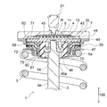
図1乃至図5は本発明の第一実施形態を示す。
図示は省略するが、例えば、懸架装置(サスペンション)1の上側は、取付部(トッププレート)7を介して自動車の本体フレーム(クロスメンバ)に固定され、下側はフレームに枢着されたロアアームを介してアクスル(車軸)に固定される。
なお、図1に示す懸架装置1は、本発明の車両の重量測定装置を組み込んだ以外は周知の構成であって、特に本実施形態に限定解釈されるものではなく本発明の範囲内で設計変更可能である。
図1中、符号3はショックアブソーバのロッド、符号5はコイルスプリングを示す。
以下、本発明の特徴的部分である車両の重量測定装置について説明し、それ以外の懸架装置の構成についての詳細な説明は省略する。
1 to 5 show a first embodiment of the present invention.
Although not shown in the drawings, for example, the upper side of the suspension device (suspension) 1 is fixed to a body frame (cross member) of an automobile via a mounting portion (top plate) 7, and the lower side is pivotally attached to the frame. It is fixed to the axle (axle) via
The suspension device 1 shown in FIG. 1 has a known configuration except that the vehicle weight measuring device of the present invention is incorporated, and is not particularly limited to the present embodiment, and is designed within the scope of the present invention. It can be changed.
In FIG. 1, reference numeral 3 denotes a shock absorber rod, and
Hereinafter, the vehicle weight measuring device which is a characteristic part of the present invention will be described, and detailed description of the configuration of the other suspension devices will be omitted.
車両の重量測定装置は、車両側に固定される取付部(トッププレート)7と、取付部7の下面7bに備えられるアウターカラー35と、前記取付部7とアウターカラー35とによって挟まれて固定されるダイアフラム11と、ダイアフラム11と当接し、ダイアフラム11を鉛直方向(図中矢印100で示す方向)に押圧可能な第1のピストン43と、前記第1のピストン43とダイアフラム11との間に配されたパッド45と、前記第1のピストン43と当接し、第1のピストン43を鉛直方向に押圧可能な第2のピストン44と、懸架装置1のコイルスプリング5の一端(上端)を受けるスプリングブッシュ47と、第2のピストン44とスプリングブッシュ47との間に介在される軸受ユニット50と、取付部7とダイアフラム11との間で形成され、所定の測定流体(作動油)Rを充填してなる油室9と、取付部7の上面7aに備えられ、油室9内に充填されている測定流体Rの圧力変化を検出し得る圧力センサ21とで構成されている(図1乃至図5参照)。
The vehicle weight measuring device is fixed by being sandwiched between an attachment portion (top plate) 7 fixed to the vehicle side, an
本実施形態では、鉛直方向でアッパーケース71から上の部材を車両側に固定される部材とするとともに、ロアーケース72から下の部材を転舵される部材とし、このアッパーケース71とロアーケース72との間にスラストニードル軸受60を介在することで軸受ユニット50を構成し、車輪を転舵方向に揺動自在に支持している。
In the present embodiment, the upper member from the
取付部(トッププレート)7は、所定の肉厚を有する短尺円筒状に形成され、上面7a側を車両側に固定するとともに、円筒状に開口する溝部9cを下面7b側に設けてなり、外周端から鉛直方向で下方に向けて円筒状に環状壁部7cを突出している。
The mounting portion (top plate) 7 is formed in a short cylindrical shape having a predetermined thickness, and the
円筒状に開口する溝部9cは、取付部7の下面7bにて円筒状に凹設されているダイアフラム収容凹部13内にて取付部7の上面7a方向に向けて形成されている。
ダイアフラム収容凹部13は、溝部9cの外径側に所定幅で環状に構成された面部13aを備えている。
The
The
前記取付部7における車体側に面した上面7aには、圧力センサ21を連結可能なセンサ連結部7dが形成されている。また、センサ連結部7dは、上面7aから溝部9cまで取付部7を鉛直方向に貫通している。
なお、センサ連結部7dと圧力センサ21との接続は、測定流体Rが漏れないよう接続することが必要である。
A
The connection between the
また、取付部7には、自動車の本体フレーム(例えばクロスメンバ)に締結固定するため、固定ボルトを挿通する複数個のボルト挿通孔を設けるとともに、後述するストッパ部49を固定するための連結ボルト17を締結する複数個のボルト固定孔7hを備えている。
In addition, the mounting
圧力センサ21は、油室9内に充填されている測定流体Rの圧力変化を検出し得るものであって、例えば、圧力を測定し、これを電圧信号に変換して伝送される周知構造のものが適宜本発明の範囲内において選択使用されるものであり、特に限定解釈はされず、本発明の範囲内で最適なものが適宜選択可能である。
本実施形態では、センサ連結部7dに検出部21aを挿入するとともに、先端検出面21bを油室9内に臨ませ、突き当てフランジ面部21cをセンサ連結部7dの開口縁に密着させて鉛直方向に立設されている。
The
In the present embodiment, the
本実施形態では、突き当てフランジ面部21cとセンサ連結部7dの開口縁部との間にワッシャ23を介して固定している。また、側定流体の漏洩防止を図るため、所定の密封装置、本実施形態ではOリング25を配設している。
なお、圧力センサ21は、必ずしも取付部7の上面7aの中心に配設することはなく、先端検出面21bが油室9内に臨む限りにおいて、センサ連結部7dを取付部7の上面7aの任意位置に設けて配設することが可能で、車体側の取り付けにおいて支障のない位置を採択して配設することが可能である。
In this embodiment, it is fixed via a
The
ダイアフラム11は、前記溝部9cの開口領域9dを覆い、前記溝部9cとともに所定空間の油室9を形成する円筒状に形成されており、取付部7の下面7bにて円筒状に形成されているダイアフラム収容凹部13に嵌着されている。
The
ダイアフラム11は、例えば、本実施形態では、外径側に肉厚の密封領域27を環状に形成するとともに、密封領域27の内径側で薄肉状に連結されて変形可能に構成された押圧領域31を備えて構成されている。
押圧領域31は、前記溝部9cの開口領域9dを覆う程度の幅をもって構成され、この押圧領域31と取付部7の溝部9cとによって所定領域の油室9が形成される。
密封領域27は、ダイアフラム収容凹部13の鉛直方向深さよりも肉厚に形成されており、アウターカラー35によって挟み込まれたときに圧縮されて密封可能な厚さとする。
In the present embodiment, for example, in the present embodiment, the
The
The sealing
ダイアフラム11の材質は、柔軟で耐久性(耐寒性・耐摩耗性・耐油性)がある素材であれば良く、特に限定解釈されるものではないが、例えば、ニトリルゴム・テフロン(登録商標)・クロロプレンゴム・ふっ素ゴム・エチレンプロピレンゴムなど、流体の特質に合った材料を選択する。また、薄肉のステンレス製などからなる金属製のダイアフラムであってもよく本発明の範囲内である。
The material of the
油室9には、所定の測定流体Rが気泡を発生させることなく一杯に密封充填されている。測定流体Rは、後述する第1のピストン43の移動によってかかる圧力が変化可能である。
The
アウターカラー35は、本実施形態では、取付部7の環状壁部7cに囲まれた領域内に収まる程度の鉛直方向の厚みをもって形成された所定の短尺円筒状に形成されるとともに、取付部7の環状壁部7cの内周面に嵌合可能な外径35dと、ダイアフラム収容凹部13の外側面部13bよりも内側に位置する環状内面35bによる内径を有する大きさに形成されている。
アウターカラー35の上面35aと、前記取付部7の下面7bにおける前記溝部9cの開口領域9dより外側の面部(ダイアフラム収容凹部13の外側面部13b)との間で、前記ダイアフラム11の密封領域29を挟み込んで密封固定している。
In the present embodiment, the
A sealing region 29 of the
また、本実施形態では、ダイアフラム11の密封領域27の上面部27aの密封固定領域A1と、ダイアフラム11の密封領域27の下面部27bとアウターカラー35の上面35aとの間の密封固定領域A2は、それぞれ面シールによる密封構造を採用している。
In the present embodiment, the sealing and fixing region A1 of the
また、これら面シールによる密封構造とともに、別途シール部材による密封構造をも併せて採用している。 In addition to the sealing structure using these face seals, a sealing structure using a separate sealing member is also employed.
本実施形態では、ダイアフラム収容凹部13の面部13aに環状のシール溝39を設けるとともに、Oリング41を挿入して密封領域27の上面部27aとの間で前記Oリング41が圧縮されて密封している。
さらに、アウターカラー35の上面35aに大小径の異なる二つの環状のシール溝39を設けるとともに、それぞれのシール溝39にOリング41を挿入して密封領域27の下面部27bとの間、取付部7の下面7bとの間で、前記それぞれのOリング41が圧縮されて密封している。
In the present embodiment, an
Further, two
密封領域27の上面部27aとの間で前記Oリング41が圧縮されて密封しているため、油室9からの測定流体Rの漏洩防止が十分に図り得るが、本実施形態によれば、上述のとおり幾重もの密封構造を採用しているため、もしも密封領域27の密封構造から測定流体Rの漏れが発生したとしても、その他の密封構造領域にて測定流体Rの漏洩が防げるため、油室9からの測定流体Rの漏洩防止が確実に図り得る。よって、密封信頼性が極めて高いものとなる。
また、本実施形態では、上述のとおり相対移動がない領域に密封構造を設けたためシール耐久性も高い。
Since the O-
Moreover, in this embodiment, since the sealing structure is provided in the region where there is no relative movement as described above, the sealing durability is high.
前記各シール部材は、密封固着領域及び当接領域を構成する一方の部材にシール溝39を設けるとともに、前記シール溝39にOリング41を挿入して他方の部材との間で前記Oリング41が圧縮されて密封しているものであればよく、シール溝39とOリング41をいずれに設けるかは限定されずいずれであっても本発明の範囲内である。
Each of the sealing members is provided with a sealing
第1のピストン43は、本実施形態では、アウターカラー35の環状内面部35b(アウターカラー35の内径)に摺接する外径を有する円筒部43aと、円筒部43aの外径から水平方向に連続して一体に、アウターカラー35の外径よりも大径に設けたフランジ部43bと、フランジ部43bの内径から一体に垂下して形成され、環状内面部43dとテーパ状外面部43eによるテーパ円筒部43cとで構成されている。
また、フランジ部43bの下面の外周端43jには、面取部43kが形成されている。
円筒部43aの上面43f側には、前記取付部7の溝部9cよりも小径の円筒状に開口する上溝部43hが形成され、円筒部43aの下面43g側には、上溝部43hよりも小径の円筒状に開口する下溝部43iが形成されている。
In the present embodiment, the
A chamfered
On the
また、前記第1のピストン43の上溝部43hには、上溝部43hの開口領域を覆い、上溝部43hの鉛直方向深さよりも肉厚の円筒状に形成されたパッド45が嵌着されている。パッド45が上溝部43hの鉛直方向深さよりも肉厚であるため、パッド45の上面がダイアフラム11の下面に当接した状態で、第1のピストン43の円筒部43aの上面43fとダイアフラム11との間、および、第1のピストン43のフランジ部43bの上面43mとアウターカラー35の下面35cとの間には、それぞれ、隙間37を有してセットされる。これにより、第1のピストン43が鉛直方向に移動可能に備えられる。
また、特に限定解釈されるものではないが、パッド45は、ダイアフラム11と第1のピストン43との間で摺動するため、自己潤滑性に優れた硬質の合成樹脂材、例えばデルリン(登録商標)等のポリアセタール樹脂からなるものなどが好ましい。また、パッド45の上面に設けた溝に潤滑剤を充填してパッド45とダイアフラム11との摺動面を潤滑してもよい。なお、パッド45を介さずに直接第1のピストン43が当接する形態であっても本発明の範囲内である。
A
Although not particularly limited, since the
第2のピストン44は、本実施形態では、前記第1のピストン43の環状内面部43d(テーパ円筒部43cの内面)と同径の環状内周面44eを有する薄肉の長尺円筒部44aと、長尺円筒部44aの下端から水平方向に連続して一体に設けられ、中央にロッド挿通孔44fを有する薄肉の底部44bと、長尺円筒部44aの上端から拡開状に鉛直方向で上方に向けて一体に設けた薄肉のテーパ円筒部44cと、テーパ円筒部44cの外周端から水平方向に連続して一体に、前記第1のピストン43のフランジ部43bと同一外径に形成した薄肉のフランジ部44dとで構成されている。
また、フランジ部44dの外径端は、拡開状に鉛直方向で上方に向けて嵌合部44gが、前記第1のピストン43のフランジ部43bの面取部43kに沿うように形成されている。
In the present embodiment, the
Further, the outer diameter end of the
また、第2のピストン44の長尺円筒部44aの内側空間には、長尺円筒形のゴムブッシュ46とともに、ゴムブッシュ46の中央に嵌着されたブッシュ内金属部材46eが格納されている。
また、ゴムブッシュ46の内周面46bの鉛直方向中央位置に、嵌合凹部46cが形成されている。嵌合凹部46cには、ブッシュ内金属部材46eが嵌着されている。
ゴムブッシュ46は、例えば、本実施形態では、内径側に外径側よりも鉛直方向に肉厚な係止領域46aが形成されている。係止領域46aは、第2のピストン44の長尺円筒部44aの鉛直方向深さよりも上下に突出した肉厚に形成されており、第1のピストン43の円筒部43aの下面43gによって挟み込まれて、嵌合凹部46cに嵌着されたブッシュ内金属部材46eを強固に保持する。
In addition, in the inner space of the long
A
In the
ブッシュ内金属部材46eは、ゴムブッシュ46の嵌合凹部46cの内周面46dと同径の外径を有し、ブッシュ内金属部材46eの上面46f側の中心には、ゴムブッシュ46の内周面46bと同径の円筒状に開口する上溝部46gが形成されている。上溝部46gには、その中心に上下方向に貫通するロッド挿通孔46hを設けている。ロッド挿通孔46hには、ロッド3a先端の段差部3a´が当接可能な受け部を設けて大径孔部と小径孔部が連続して形成されている。
The
第2のピストン44は、長尺円筒部44aの内側空間に内在するブッシュ内金属部材46eのロッド挿通孔46hに挿通して、ブッシュ内金属部材46eの上面46f側に突出した懸架装置1を構成するショックアブソーバ3のロッド3a先端を、ナット4を介して取り付け締結するとともに、締結部をゴムブッシュ46に支えられ、懸架装置1の長さ方向に移動可能に備えられている。
そして、第2のピストン44のフランジ部44dと鉛直方向に密接する第1のピストン43のフランジ部43bを介して、第1のピストン43の上溝部43hに嵌着されたパッド45で、懸架装置1のスプリング5の弾発力により前記ダイアフラム11を押圧可能に備えられている。
The
Then, a suspension device is provided with a
軸受ユニット50は、前記第2のピストン44のフランジ部44dの下面と、後述するスプリングブッシュ47のフランジ部47cの上面との間に介在されて相対回転可能に構成されており、本実施形態では、懸架装置の長さ方向の荷重を揺動自在に支持するスラストニードル軸受60と,揺動に一定減衰を発生させ、かつ長さ方向の荷重は受けず径方向の荷重を受けるすべりブッシュ75を備え、スラストニードル軸受60とすべりブッシュ75を収容するケース70とで構成されている(図5参照)。
The bearing
前記スラストニードル軸受60は、相対回転可能に上下に対向配置されたアッパーレース(アッパー軌道輪)61とロアーレース(ロアー軌道輪)62と、これら一対のレース61・62相互間に構成された軸受内部空間に沿って配列された転動体としての複数の針状ころ63と、複数の針状ころ63を回転可能に保持する保持器64とで構成されている。
The
アッパーレース61は、下面に軌道面61aを有した円環状に形成されている。
ロアーレース62は、上面に軌道面62aを有し、アッパーレース61よりも幅広に形成された円環部62bと、円環部62bの外径端から一体に垂設された円筒部62cとで形成されている。
アッパーレース61とロアーレース62は、軌道面61aおよび軌道面62aが対向配置されるように組み合わされている。
The
The
The
ケース70は、アッパーケース71と、ロアーケース72とによって、前記スラストニードル軸受60を挟み込むように構成されている。
アッパーケース71は、前記スラストニードル軸受60のアッパーレース61の上面61bと、前記第2のピストン44のフランジ部44dの下面との間に介在し、ロアーケース72は、スラストニードル軸受60のロアーレース62の下面62dと、後述するスプリングブッシュ47のフランジ部47cとの間に介在している。
The
The
アッパーケース71は、本実施形態では、前記第2のピストン44のフランジ部44dの嵌合部44g(フランジ部44dの外径端)から前記スラストニードル軸受60のアッパーレース61の上面61bを覆い、アッパーレース61が嵌着する嵌着凹部71eを下面に設けた大径円環部71aと、大径円環部71aの内径から拡開状に鉛直方向で下方に向けて一体に設けたテーパ円筒部71bと、テーパ円筒部71bの下端から、第2のピストン44の長尺円筒部44aまで水平方向に一体に設けた段部71cと、段部71cから一体に第2のピストン44の長尺円筒部44aに沿って鉛直方向で下方に向けて垂設した円筒部71dとで形成されている。
In this embodiment, the
また、アッパーケース71の大径円環部71aの外径から一体に垂下して、前記ロアーレース62の円環部62bと僅かな隙間を持って形成された薄肉円筒部71fと、大径円環部71aの外径から水平方向に連続して一体に、ロアーレース62の円筒部62cを越えて外径方向に設けた延出円環部71gと、延出円環部71gの外径にて、ロアーレース62の円筒部62cと所定の隙間を有し、ロアーレース62の円環部62bを越えて垂下して薄肉に設けた垂下円筒部71hが形成されている。
Further, a thin
ロアーケース72は、本実施形態では、前記スラストニードル軸受60のロアーレース62の下面62dを覆う大径円環部72aと、大径円環部72aの内径から水平方向に、前記アッパーケース71の大径円環部71aと僅かな隙間を持って肉厚で設けられた肉厚部72bと、肉厚部72b内径から拡開状に鉛直方向で下方に向けて一体に、前記アッパーケース71のテーパ円筒部71bと隙間を持って対向して設けたテーパ円筒部72cと、テーパ円筒部72cの下端から一体に鉛直方向で下方に向け、前記アッパーケース71の円筒部71dと対向して垂下した円筒部72dとで構成されている。また、円筒部72dの内周面72eには収容凹部72fが、前記アッパーケース71の円筒部71dと対向して形成されている。
In the present embodiment, the
すべりブッシュ75は、前記収容凹部72fに収容され、対向するアッパーケース71の円筒部71dと摺接する肉厚で円筒状に形成されている。
すべりブッシュ75の材質としては、耐摩耗性と所定の減衰特性を備えた素材であれば良く、特に限定解釈されるものではないが、例えば、テフロン(登録商標)などの樹脂材料を選択する。
The sliding
The material of the sliding
本実施形態では、スラスト配置した前記スラストニードル軸受60により、転舵方向に揺動する際の摩擦を非常に小さくし、車体重量を揺動自在に支持するとともに、アッパーケース71の円筒部71dとロアーケース72の円筒部72dとの間にて、鉛直方向にすべりブッシュ75を配したので、すべりブッシュ75には車体重量が負荷されず、すべりブッシュ75がアッパーケース71の円筒部71dと摺接することによって、ロアーケース72の旋回方向の揺動に対して所定の減衰を発生させることができる。
In the present embodiment, the
また、本実施形態の軸受ユニットでは、軸受ユニットの外部からの異物の浸入を防止するため、シール66を配している。
シール66は、ロアーレース62の円筒部62cを心金として、円筒部62cの上面62e寄りの軸方向内側面の一面から軸方向外側面(外周面)62fの全面にわたって弾性材66aで被覆するとともに、前記軸方向外側面(外周面)62fを覆う部分から第1のリップ67と第2のリップ68が一体形成されている。
なお、シール66は、例えばゴムやエラストマーなどの周知の弾性材が本発明の範囲内で適宜選択して採用される。
Further, in the bearing unit of the present embodiment, a
The
For the
第1のリップ67は、シール66の外周側66bにおいて、基部67aからアッパーケース71の垂下円筒部71hの内周面71iに向けて下向き傾斜で、全周にわたって突出して略傘状に形成されて、リップ先端67bが垂下円筒部71hの内周面71iと摺接している。すなわち、この第1のリップ67と垂下円筒部71hの内周面71iとの摺接による密封領域を構成しており、軸受内部(空間)に異物が侵入しないように作用している。
第2のリップ68は、第1のリップ67よりも外気側に備えられ、シール66の外周側66bにおいて、基部68aからアッパーケース71の垂下円筒部71hの内周面71iに向けて下向き傾斜で、全周にわたって突出して略傘状に形成されて、リップ先端68bが垂下円筒部71hの内周面71iと摺接している。すなわち、この第2のリップ68も、前記第1のリップ67の外気側で、垂下円筒部71hの内周面71iとの摺接による密封領域を構成しており、軸受内部(空間)に異物が侵入しないように作用している。
さらに、ロアーレース62は、アッパーケース71の延出円環部71gと薄肉円筒部71fに近接対向して配されており、これにより、ラビリンス隙間を形成して密封領域を構成している。
The first lip 67 is inclined in the downward direction from the
The
Further, the
また、アッパーケース71とロアーケース72は、ケース70の分解防止用の固定手段を備えている。
本実施形態では、固定手段は、例えば、アッパーケース71の円筒部71dの下端71kに設けられたアッパーケース側爪部(嵌合爪)80と、ロアーケース72の円筒部72dの下端72gに設けられたロアーケース側爪部(嵌合爪)81とが互いに噛み合うように構成されている。
Further, the
In the present embodiment, for example, the fixing means is provided at the upper case side claw portion (fitting claw) 80 provided at the
アッパーケース側爪部80は、アッパーケース71の円筒部71dの下端71kから垂下して備えられ、基部80aから先端側80bにかけてなだらかに内径方向に突出した膨出部80cが形成されている。
ロアーケース側爪部81は、ロアーケース72の円筒部72dの下端72gから水平方向で一体に、前記アッパーケース側爪部80を越えて、前記アッパーケース71の円筒部71dと同径の内周面を有して延出した延出部81aから、アッパーケース71の円筒部71dの下端71kに向けて備えられ、基部81bから先端側81cにかけてなだらかに内径方向に突出した膨出部81dが形成されている。
The upper case
The lower case
アッパーケース71とロアーケース72とを組み合わせるときに、アッパーケース側爪部80が、ロアーケース側爪部81とロアーケース72の円筒部72dとの隙間に押し込まれることで、アッパーケース側爪部80の膨出部80cとロアーケース側爪部81の膨出部81dとが互いにかみ合って嵌着され、軸受ユニット50の分解が防止される。
When the
本実施形態では、アッパーケース71とロアーケース72との組み合わせ作業を容易にするため、ロアーケース72が弾性を備えた材質(弾性材)で形成されている。例えば、本実施形態のロアーケース72は、樹脂素材により形成されている。
ロアーケース72が樹脂素材で形成されることによって、その弾性により、ロアーケース側爪部81をロアーケース72の円筒部72dから離間するように押し広げることが容易である。このため、アッパーケース71とロアーケース72とを組み合わせる際に、ロアーケース側爪部81とロアーケース72の円筒部72dとの隙間にアッパーケース側爪部80を差し込み易いので、アッパーケース側爪部80の膨出部80cとロアーケース側爪部81の膨出部81dとの嵌着作業が容易になる。
In the present embodiment, in order to facilitate the combination work of the
Since the
なお、ロアーケース72を形成する弾性材の硬度(柔らかさ)については、ロアーケース側爪部81を押し広げ易く、かつ、アッパーケース71とロアーケース72との組み合わせ後において、アッパーケース側爪部80の膨出部80cとロアーケース側爪部81の膨出部81dとの嵌着が容易に解けない程度の柔らかさを備えていれば良い。
また、本実施形態では、ロアーケース72を形成する弾性材として樹脂素材を選択したが、これに限定解釈されるものではなく、アッパーケース側爪部80とロアーケース側爪部81との嵌着が容易かつ確実であれば任意に選択されれば良い。
さらに、アッパーケース側爪部80の膨出部80cとロアーケース側爪部81の膨出部81dとの嵌着作業を容易にするため、本実施形態では、図示を省略するが、ロアーケース72の円筒部72dの下端72g側に、周方向に所定の間隔で数箇所、スリットが形成されている。
このように、ロアーケース72にスリットを形成したことによって、アッパーケース側爪部80の膨出部80cとロアーケース側爪部81の膨出部81dとの嵌着作業において、ロアーケース72の円筒部72dの周方向の一部の下端72gをスリットで撓ませることにより、ロアーケース側爪部81がロアーケース72の円筒部72dから離間するように押し広げられるので嵌着作業が容易となる。
なお、ロアーケース72に形成されるスリットの数や長さについては、任意に選択されればよい。
In addition, regarding the hardness (softness) of the elastic material forming the
In this embodiment, the resin material is selected as the elastic material for forming the
Further, in order to facilitate the fitting operation between the bulging
Thus, by forming the slit in the
Note that the number and length of the slits formed in the
なお、本実施形態では、固定手段として、アッパーケース側爪部80とロアーケース側爪部81との嵌合爪同士が互いに噛み合う構成を採用したが、アッパーケース71とロアーケース72との分解を防止し得る構成であれば他の構成が採用されてもよい。例えば、アッパーケース71の円筒部71dの下端71kと、ロアーケース72の円筒部72dの下端72gを重ね合わせて、下端71kと下端72gとをクリップ状の部材で嵌着する構成であってもよい。
In the present embodiment, as the fixing means, a configuration in which the fitting claws of the upper case
スプリングブッシュ47は、前記軸受ユニット50のロアーケース72の円筒部72dを内装可能な円筒状の貫通孔47bを備えた大径状円筒部47aと、大径状円筒部47aの上端から水平方向で外側に向けて連続して一体に設けたフランジ部47cと、を備えて構成されている。大径状円筒部47aは上下面を開口して形成されている。
フランジ部47cの下面には、懸架装置1を構成するコイルスプリング5の一端(上端)5aが鉛直方向で突き当たる(図1参照)。
The
One end (upper end) 5a of the
ストッパ部49は、懸架装置1への取り付け作業性を向上させるために採用されているものであって、本実施形態では、取付部7と同一外径で、かつ内径は、第1のピストン43のフランジ部43bと、第2のピストン44のフランジ部44dよりもわずかに大径で円環状に形成された環状取付部49aと、環状取付部49aの内径から鉛直方向で下方に向けて垂設された円筒部49bと、円筒部49bの下端から水平方向で内側に向けて、軸受ユニット50のアッパーケース71の大径円環部71aよりもわずかに大径で突設された係止鍔部49cとで構成されている。
環状取付部49aには、取付部7のボルト固定孔7hに鉛直方向で同軸に配されるようにボルト挿通孔49dが形成されている。
The
A
従って、ストッパ部49のボルト挿通孔49dを、取付部7のボルト固定孔7hを介して同軸上に連通させ、連結ボルト17を介して締結すると、係止鍔部49cが、第2のピストン44のフランジ部44dを鉛直方向で下方から受けるようにして係止して、第1のピストン43と第2のピストン44を隙間37(第1のピストン43の円筒部43aの上面43fとダイアフラム11との隙間37、および、第1のピストン43のフランジ部43bの上面43mとアウターカラー35の下面35cとの隙間37)の範囲内で鉛直方向に移動可能に取付部7と一体化させることができる。
「第二実施形態」
Therefore, when the
"Second embodiment"
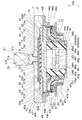
図6乃至図8は本発明の第二実施形態を示す。 6 to 8 show a second embodiment of the present invention.
本実施形態の車両の重量測定装置は、車両側に固定される取付部(トッププレート)7と、取付部7の下面7bに備えられるカラー35と、前記取付部7とカラー35とによって挟まれて固定されるダイアフラム11と、ダイアフラム11と当接し、ダイアフラム11を鉛直方向(図中矢印100で示す方向)に押圧可能な第1のピストン43と、前記第1のピストン43と当接し、第1のピストン43を鉛直方向に押圧可能な第2のピストン44と、懸架装置1のコイルスプリング5の一端(上端)を受けるスプリングブッシュ(スプリングシート)47と、取付部7とダイアフラム11との間で形成され、所定の測定流体(作動油)Rを充填してなる油室9と、取付部7の上面7aに備えられ、ピストン(第1のピストン43、第2のピストン44)の移動により、油室9内に充填されている測定流体Rの圧力変化を検出し得る圧力センサ21とで構成されている(図6至図8参照)。
The vehicle weight measuring device of the present embodiment is sandwiched between an attachment portion (top plate) 7 fixed to the vehicle side, a
本実施形態では、第一実施形態とは異なり、鉛直方向でカラー35、取付部7及びダイアフラム11から上の部材を車両側に固定される部材とするとともに、第一のピストン43から下の部材を転舵される部材とし、このカラー35、取付部7及びダイアフラム11を含む車両側に固定される部材と、第一のピストン43を含む転舵される部材との間にスラストニードル軸受60を介在し、車両側に固定される部材と転舵される部材とを相対回転可能に構成し、車輪を転舵方向に揺動自在に支持している。
さらに本実施形態では、スラストニードル軸受60とダイアフラム11との間にスラストプレート90が介在されている。
In the present embodiment, unlike the first embodiment, the upper member from the
Further, in the present embodiment, a
すなわち、第一実施形態では、スプリングブッシュ47とピストン(第2のピストン44)との間に軸受ユニット50(スラストニードル軸受60)を介在した構成を採用しているのに対し、本実施形態では、ピストン(第1のピストン43)とダイアフラム11との間にスラストニードル軸受60を介在した構成を採用している点で異なる。
このように構成することにより、重量測定装置全体の鉛直方向厚さを第一実施形態と比して薄く構成することが可能となる。
That is, in the first embodiment, a configuration in which the bearing unit 50 (thrust needle bearing 60) is interposed between the
By comprising in this way, it becomes possible to comprise the thickness of the whole weight measuring apparatus thinly compared with 1st embodiment.
取付部7、ダイアフラム11、第1のピストン43、第2のピストン44、スプリングブッシュ(スプリングシート)47、油室9、圧力センサ21及びその他の構成にあっては、第一実施形態を構成するそれぞれの部材と同一であり、それらの詳細な説明は省略する。
また、本実施形態で採用しているカラー35は、第一実施形態で説明したアウターカラー35と同一構成であるためその詳細な説明も省略する。
The mounting
Further, since the
スラストニードル軸受60は、第一実施形態でパッド45が収容されている領域、すなわち、第1のピストン43の上溝部43hに収容されている。
図中符号65はケージを示す。本実施形態では、上溝部43hの鉛直方向深さよりも大径の断面視円形状に形成されたころ63が、スラストプレート90の下面に当接した状態で備えられる。
The
スプリングブッシュ47は、第2のピストン44の長尺円筒部44aを内装可能な円筒状の貫通孔47bを備えた大径状円筒部47aと、大径状円筒部47aの上端から水平方向で外側に向けて連続して一体に設けたフランジ部47cと、を備えて構成されている。大径状円筒部47aは上下面を開口して形成されている。
The
フランジ部47cの下面には、懸架装置1を構成するコイルスプリング5の一端(上端)5aが鉛直方向で突き当たり、上面には第2のピストン44のフランジ部44dが当接している(図6参照)。
One end (upper end) 5a of the
ストッパ部49は、本実施形態では、係止鍔部49cが、第2のピストン44の嵌合部44gに嵌合可能に形成されている。
環状取付部49aには、取付部7のボルト固定孔7hに鉛直方向で同軸に配されるようにボルト挿通孔49dが形成されている。
In the present embodiment, the
A
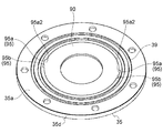
スラストプレート90は、カラー35の内径に嵌合可能な外径と、スラストニードル軸受60の内径よりも小径な内径と、第1のピストン43の上溝部43hの上縁部とカラー35の内径とで構成される空間領域に収容される厚さを有する円板状に形成され、カラー35の内径とともに構成する回転不能機構95を介してダイアフラム11と第1のピストン43との間に介在されている。
The
回転不能機構95は、本実施形態では、スラストプレート90の外径とカラー35の内径との対向領域に設けた凹凸構造を採用している。
In this embodiment, the
凹凸構造は、スラストプレート90のカラー対向面に設けた凸部95aと、カラー35のスラストプレート対向面に設けた凹部95bと、により構成されている。なお、本実施形態では、スラストプレート90の外径において、スラストプレート90の中心を通る線上に対向して一対の凸部95a,95aが形成されている。また、カラー35の内径においても、カラー35の中心を通る線上に対向して、前記一対の凸部95a,95aが嵌合可能な一対の凹部95b,95bが形成されている。
The concavo-convex structure is constituted by a
凸部95aは、スラストプレート90の鉛直方向の板厚と同一の厚さを有するとともに、所定の周方向長さをもって形成されている。凹部95bは、凸部95aが嵌合可能な形態をもって形成されており、本実施形態では、凸部95aの下面95a1を受ける底面95b1を有した凹状に形成されており、凸部95aは上面95a2が突出することなく凹部95b内に収容可能に嵌合されている。
The
本実施形態によれば、スラストプレート90はダイアフラム11と相対回転しないため、第一実施形態で採用しているパッド45は不要となる。
According to this embodiment, since the
凹凸構造は、本実施形態とは逆に、スラストプレートのカラー対向面に設けた凹部と、カラーのスラストプレート対向面に設けた凸部と、により構成されている構造を採用することも可能で、本発明の範囲内で適宜設計変更可能である。
また、一対の凸部95a,95aの形状・大きさは特に図示形態に限定解釈されるものではなく本発明の範囲内で設計変更可能である。
また、凸部95aと凹部95bとは、複数個でも単数個でもよく任意である。さらに、スラストプレート90の外径とカラー35の内径とが、それぞれ嵌合可能な連続した凹凸面に形成されているものであってもよい。
「第三実施形態」
Contrary to this embodiment, the concavo-convex structure may adopt a structure constituted by a concave portion provided on the collar facing surface of the thrust plate and a convex portion provided on the collar facing surface of the collar. The design can be changed as appropriate within the scope of the present invention.
Further, the shape and size of the pair of
Moreover, the
"Third embodiment"
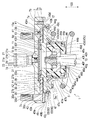
図9は本発明の第三実施形態を示す。 FIG. 9 shows a third embodiment of the present invention.
本実施形態の車両の重量測定装置は、第二実施形態の車両の重量測定装置において採用しているスラストプレート90を取り除き、ダイアフラム11を針状ころ63の転動面として利用する実施の一形態である。その他の構成及び作用効果は第一実施形態と第二実施形態と同様であるため第一実施形態と第二実施形態の説明を援用してここでの詳細な説明は省略する。
The vehicle weight measuring device according to the present embodiment is an embodiment in which the
本実施形態によれば、車両の重量測定装置の部品点数を削減でき、コストダウンと組立性の向上が図り得る。また、重量測定装置全体の鉛直方向厚さをさらに薄く構成することが可能である。
なお、例えば、小型車やコミュータ等の重量が軽い車両に本実施形態を適用する場合には、ダイアフラム11の材質は特に限定されないが、重量が重い車両に本実施形態を適用する場合、ダイアフラム11は、バネ性のある鋼材とするのが好ましい。
According to the present embodiment, the number of parts of the vehicle weight measuring device can be reduced, and the cost can be reduced and the assemblability can be improved. Further, it is possible to further reduce the vertical thickness of the entire weight measuring device.
For example, when the present embodiment is applied to a light vehicle such as a small car or a commuter, the material of the
本発明は、本実施形態に示す構成からなる懸架装置に係らず、他の構成からなる懸架装置にも利用可能である。 The present invention is not limited to the suspension device having the configuration shown in the present embodiment, but can be used for a suspension device having another configuration.
1 懸架装置
7 取付部
9 油室
9c 溝部
9d 開口領域
11 ダイアフラム
13a ダイアフラムの外径よりの面部
21 圧力センサ
35 アウターカラー
43 第1のピストン
43b 第1のピストンのフランジ部
44 第2のピストン
44d 第2のピストンのフランジ部
47 スプリングブッシュ
50 軸受ユニット
60 スラストニードル軸受
75 すべりブッシュ
R 測定流体
DESCRIPTION OF SYMBOLS 1
Claims (8)
上面側を車両側に固定するとともに、下面側に開口する溝部を有する取付部と、
前記溝部の開口領域を覆い、前記溝部とともに所定空間の油室を形成するダイアフラムと、
前記溝部の開口領域の外径よりも大径に形成され、前記ダイアフラムの外径寄りの面部を、前記溝部の開口領域より外側の面部との間で挟み込んで密閉固定するカラーと、
スプリングの弾発力により前記ダイアフラムを押圧可能なピストンと、
前記取付部に備えられ、前記ピストンの移動により変化可能な油室内の測定流体の圧力変化を検出し得る圧力センサと、を含むことを特徴とする車両の重量測定装置。 It is provided in the suspension device, and supports the wheel so as to be swingable in the steering direction by interposing a bearing between the member fixed to the vehicle side and the member to be steered,
An attachment portion having a groove portion that opens to the lower surface side while fixing the upper surface side to the vehicle side,
A diaphragm that covers an opening region of the groove and forms an oil chamber of a predetermined space together with the groove;
A collar that is formed larger than the outer diameter of the opening area of the groove portion, and that has a surface portion near the outer diameter of the diaphragm sandwiched between a surface portion outside the opening area of the groove portion and hermetically fixed,
A piston capable of pressing the diaphragm by the spring force of a spring;
A vehicle weight measuring device comprising: a pressure sensor provided in the mounting portion and capable of detecting a pressure change of a measurement fluid in an oil chamber that can be changed by movement of the piston.
上面側を車両側に固定するとともに、下面側に開口する溝部を有する取付部と、
前記溝部の開口領域を覆い、前記溝部とともに所定空間の油室を形成するダイアフラムと、
前記溝部の開口領域の外径よりも大径に形成され、前記ダイアフラムの外径寄りの面部を、前記溝部の開口領域より外側の面部との間で挟み込んで密閉固定する環状のアウターカラーと、
前記アウターカラーの内径側で懸架装置の長さ方向に移動可能に備えられるとともに、前記アウターカラーの下側にアウターカラーと隙間を介して配されるフランジ部を備え、懸架装置のスプリングの弾発力により前記ダイアフラムを押圧可能な第1のピストンと、
前記第1のピストンの下面に当接するフランジ部を備えるとともに、中空な内部空間を備えた長尺円筒部に、下方から懸架装置の先端部を挿し込んで収容可能な第2のピストンと、
前記スプリングの一端を受けるスプリングブッシュと、
前記スプリングブッシュと前記第2のピストンとの間に介在され、相対回転可能に構成されている軸受ユニットと、
前記取付部に備えられ、前記ピストンの移動により変化可能な油室内の測定流体の圧力変化を検出し得る圧力センサと、を含み、
前記軸受ユニットは、懸架装置の長さ方向の荷重を揺動自在に支持するスラストニードル軸受と,揺動に一定減衰を発生させ、かつ長さ方向の荷重は受けず径方向の荷重を受けるすべりブッシュを備えることを特徴とする車両の重量測定装置。 It is provided in the suspension device, and supports the wheel so as to be swingable in the steering direction by interposing a bearing between the member fixed to the vehicle side and the member to be steered,
An attachment portion having a groove portion that opens to the lower surface side while fixing the upper surface side to the vehicle side,
A diaphragm that covers an opening region of the groove and forms an oil chamber of a predetermined space together with the groove;
An annular outer collar that is formed larger than the outer diameter of the opening region of the groove portion, and sandwiches and fixes the surface portion near the outer diameter of the diaphragm with the surface portion outside the opening region of the groove portion;
The outer collar is provided with a flange portion that is movable in the length direction of the suspension device on the inner diameter side of the outer collar, and has a flange portion that is arranged through a gap with the outer collar on the lower side of the outer collar. A first piston capable of pressing the diaphragm by force;
A second piston that includes a flange portion that contacts the lower surface of the first piston, and that can be accommodated by inserting the distal end portion of the suspension device from below into a long cylindrical portion having a hollow internal space;
A spring bush for receiving one end of the spring;
A bearing unit interposed between the spring bush and the second piston and configured to be relatively rotatable;
A pressure sensor provided in the mounting portion and capable of detecting a pressure change of a measurement fluid in an oil chamber that can be changed by movement of the piston;
The bearing unit includes a thrust needle bearing that supports the longitudinal load of the suspension device in a swingable manner, and a slide that generates a constant damping in the swing and receives a radial load without receiving a load in the longitudinal direction. A vehicle weight measuring device comprising a bush.
相対回転可能に上下に対向配置された円環状の一対のレースと、
これら一対のレース相互間に構成された軸受内部空間に沿って配列された複数の針状ころと、
前記複数の針状ころを回転可能に保持する保持器と、を含み、
前記軸受ユニットは、
前記スラストニードル軸受のアッパーレースに当接して配されたアッパーケースと、
前記スラストニードル軸受のロアーレースに当接して配されたロアーケースと、を含み、
前記ロアーレースは、前記アッパーケースとの間にシールを備えていることを特徴とする請求項2に記載の車両の重量測定装置。 The thrust needle bearing is
A pair of annular races arranged vertically opposite to each other so as to be relatively rotatable;
A plurality of needle rollers arranged along a bearing internal space formed between the pair of races;
A retainer for rotatably holding the plurality of needle rollers,
The bearing unit is
An upper case disposed in contact with the upper race of the thrust needle bearing;
A lower case disposed in contact with the lower race of the thrust needle bearing,
The vehicle weight measuring device according to claim 2, wherein the lower race includes a seal between the lower race and the upper case.
上面側を車両側に固定するとともに、下面側に開口する溝部を有する取付部と、
前記溝部の開口領域を覆い、前記溝部とともに所定空間の油室を形成するダイアフラムと、
前記溝部の開口領域の外径よりも大径に形成され、前記ダイアフラムの外径寄りの面部を、前記溝部の開口領域より外側の面部との間で挟み込んで密閉固定するカラーと、
スプリングの弾発力により前記ダイアフラムを押圧可能なピストンと、
前記取付部に備えられ、前記ピストンの移動により変化可能な油室内の測定流体の圧力変化を検出し得る圧力センサと、を含み、
前記軸受は、スラストニードル軸受で、前記ダイアフラムと前記ピストンとの間に介在されていることを特徴とする車両の重量測定装置。 It is provided in the suspension device, and supports the wheel so as to be swingable in the steering direction by interposing a bearing between the member fixed to the vehicle side and the member to be steered,
An attachment portion having a groove portion that opens to the lower surface side while fixing the upper surface side to the vehicle side,
A diaphragm that covers an opening region of the groove and forms an oil chamber of a predetermined space together with the groove;
A collar that is formed larger than the outer diameter of the opening area of the groove portion, and that has a surface portion near the outer diameter of the diaphragm sandwiched between a surface portion outside the opening area of the groove portion and hermetically fixed,
A piston capable of pressing the diaphragm by the spring force of a spring;
A pressure sensor provided in the mounting portion and capable of detecting a pressure change of a measurement fluid in an oil chamber that can be changed by movement of the piston;
The vehicle weight measuring device according to claim 1, wherein the bearing is a thrust needle bearing and is interposed between the diaphragm and the piston.
Priority Applications (5)
| Application Number | Priority Date | Filing Date | Title |
|---|---|---|---|
| EP17913321.0A EP3640611A4 (en) | 2016-06-17 | 2017-12-15 | Vehicle weight measurement device |
| PCT/JP2017/045094 WO2018230015A1 (en) | 2016-06-17 | 2017-12-15 | Vehicle weight measurement device |
| JP2018557161A JP6501048B1 (en) | 2016-06-17 | 2017-12-15 | Vehicle weight measuring device |
| US16/623,193 US11002311B2 (en) | 2016-06-17 | 2017-12-15 | Vehicle weight measurement device |
| CN201780092152.0A CN110753832A (en) | 2016-06-17 | 2017-12-15 | Vehicle weight measuring device |
Applications Claiming Priority (2)
| Application Number | Priority Date | Filing Date | Title |
|---|---|---|---|
| JP2016121056 | 2016-06-17 | ||
| JP2016121056 | 2016-06-17 |
Publications (1)
| Publication Number | Publication Date |
|---|---|
| JP2017227634A true JP2017227634A (en) | 2017-12-28 |
Family
ID=60891509
Family Applications (2)
| Application Number | Title | Priority Date | Filing Date |
|---|---|---|---|
| JP2017118514A Pending JP2017227634A (en) | 2016-06-17 | 2017-06-16 | Weight measurement device of vehicle |
| JP2018557161A Active JP6501048B1 (en) | 2016-06-17 | 2017-12-15 | Vehicle weight measuring device |
Family Applications After (1)
| Application Number | Title | Priority Date | Filing Date |
|---|---|---|---|
| JP2018557161A Active JP6501048B1 (en) | 2016-06-17 | 2017-12-15 | Vehicle weight measuring device |
Country Status (5)
| Country | Link |
|---|---|
| US (1) | US11002311B2 (en) |
| EP (1) | EP3640611A4 (en) |
| JP (2) | JP2017227634A (en) |
| CN (1) | CN110753832A (en) |
| WO (1) | WO2018230015A1 (en) |
Cited By (2)
| Publication number | Priority date | Publication date | Assignee | Title |
|---|---|---|---|---|
| WO2019003471A1 (en) * | 2016-06-29 | 2019-01-03 | 日本精工株式会社 | Vehicle weight measurement device |
| JP2021143735A (en) * | 2020-03-12 | 2021-09-24 | 中西金属工業株式会社 | Strut bearing and strut type suspension of vehicle |
Families Citing this family (1)
| Publication number | Priority date | Publication date | Assignee | Title |
|---|---|---|---|---|
| DE102019200695A1 (en) * | 2019-01-21 | 2020-07-23 | Aktiebolaget Skf | Suspension axial bearing device and a strut equipped with such a device |
Family Cites Families (21)
| Publication number | Priority date | Publication date | Assignee | Title |
|---|---|---|---|---|
| GB472793A (en) * | 1937-02-03 | 1937-09-30 | Derek Moorhouse Livsey | Improvements in and relating to apparatus for weighing locomotives and rail vehicles |
| GB1296311A (en) * | 1971-04-07 | 1972-11-15 | ||
| FR2513334A1 (en) * | 1981-09-24 | 1983-03-25 | Nadella | Bearing for motor vehicle front suspension strut - has needle thrust rollers and ball guide bearings for axial and radial location |
| DE8801249U1 (en) | 1988-02-02 | 1989-06-01 | Pfister Gmbh, 8900 Augsburg, De | |
| DE3911601A1 (en) * | 1989-04-08 | 1990-10-11 | Vdo Schindling | LOAD SENSOR FOR A MOTOR VEHICLE |
| JPH04181132A (en) * | 1990-11-15 | 1992-06-29 | Atsugi Unisia Corp | Load sensor apparatus |
| US5979218A (en) * | 1997-11-12 | 1999-11-09 | Chrysler Corporation | Strut mount transducer |
| JP4197830B2 (en) | 2000-05-23 | 2008-12-17 | 矢崎総業株式会社 | Sensor unit for vehicle load measurement |
| JP4391406B2 (en) * | 2004-12-17 | 2009-12-24 | Ntn株式会社 | Thrust bearing |
| US7820591B2 (en) * | 2005-01-04 | 2010-10-26 | Korea Electric Power Corporation | Highly attrition resistant and dry regenerable sorbents for carbon dioxide capture |
| JP6154732B2 (en) | 2013-11-13 | 2017-06-28 | Kyb株式会社 | Rotary damper |
| JP6256168B2 (en) | 2014-04-14 | 2018-01-10 | 日本精工株式会社 | Bearing device with load sensor |
| JP5931253B1 (en) | 2014-06-30 | 2016-06-08 | 本部三慶株式会社 | A method for removing liquid calcium oxide from low-smelling odor by removing calcium from high-quality powder |
| JP6606321B2 (en) * | 2014-09-29 | 2019-11-13 | オイレス工業株式会社 | Thrust bearing for vehicles |
| EP3045374B1 (en) * | 2015-01-19 | 2020-02-26 | VR-Yhtymä Oy | Weighing arrangement |
| CN204535832U (en) * | 2015-01-20 | 2015-08-05 | 金宙科技有限公司 | Vehicle load measuring apparatus |
| JP6515770B2 (en) * | 2015-07-06 | 2019-05-22 | 日本精工株式会社 | Bearing device with load sensor |
| US20190226906A1 (en) * | 2015-12-10 | 2019-07-25 | Nsk Ltd. | Device for measuring weight of vehicle |
| JP6359616B2 (en) | 2015-12-22 | 2018-07-18 | 東芝映像ソリューション株式会社 | Transmitter |
| JP2018009980A (en) * | 2016-06-29 | 2018-01-18 | 日本精工株式会社 | Weight measurement device of vehicle |
| US20190285461A1 (en) * | 2016-07-19 | 2019-09-19 | Nsk Ltd. | Vehicle weight measurement device |
-
2017
- 2017-06-16 JP JP2017118514A patent/JP2017227634A/en active Pending
- 2017-12-15 WO PCT/JP2017/045094 patent/WO2018230015A1/en active Application Filing
- 2017-12-15 JP JP2018557161A patent/JP6501048B1/en active Active
- 2017-12-15 US US16/623,193 patent/US11002311B2/en active Active
- 2017-12-15 EP EP17913321.0A patent/EP3640611A4/en not_active Withdrawn
- 2017-12-15 CN CN201780092152.0A patent/CN110753832A/en active Pending
Cited By (3)
| Publication number | Priority date | Publication date | Assignee | Title |
|---|---|---|---|---|
| WO2019003471A1 (en) * | 2016-06-29 | 2019-01-03 | 日本精工株式会社 | Vehicle weight measurement device |
| JP2021143735A (en) * | 2020-03-12 | 2021-09-24 | 中西金属工業株式会社 | Strut bearing and strut type suspension of vehicle |
| JP7290832B2 (en) | 2020-03-12 | 2023-06-14 | 中西金属工業株式会社 | Strut bearings and vehicle strut suspensions |
Also Published As
| Publication number | Publication date |
|---|---|
| US20200378438A1 (en) | 2020-12-03 |
| CN110753832A (en) | 2020-02-04 |
| WO2018230015A1 (en) | 2018-12-20 |
| JP6501048B1 (en) | 2019-04-17 |
| JPWO2018230015A1 (en) | 2019-06-27 |
| EP3640611A4 (en) | 2020-07-01 |
| US11002311B2 (en) | 2021-05-11 |
| EP3640611A1 (en) | 2020-04-22 |
Similar Documents
| Publication | Publication Date | Title |
|---|---|---|
| JP6256168B2 (en) | Bearing device with load sensor | |
| EP3236219B1 (en) | Vehicle weight measurement device | |
| WO2018230015A1 (en) | Vehicle weight measurement device | |
| US20190285461A1 (en) | Vehicle weight measurement device | |
| US8434947B2 (en) | Sensor-equipped bearing for wheel | |
| JP6515770B2 (en) | Bearing device with load sensor | |
| JP6497490B1 (en) | Vehicle weight measuring device | |
| CN1954156A (en) | Bearing with sensor | |
| JP5063270B2 (en) | Wheel bearing with sensor | |
| JP7107282B2 (en) | vehicle weighing device | |
| JP6784189B2 (en) | Vehicle weight measuring device | |
| JP6794848B2 (en) | Vehicle weight measuring device | |
| JP6819436B2 (en) | Vehicle weight measuring device | |
| JP2003049832A (en) | Rotation supporting device with temperature sensor | |
| JP5219423B2 (en) | Wheel bearing with sensor |