JP2017227332A - Gas cylinder actuator with safety device - Google Patents
Gas cylinder actuator with safety device Download PDFInfo
- Publication number
- JP2017227332A JP2017227332A JP2017123024A JP2017123024A JP2017227332A JP 2017227332 A JP2017227332 A JP 2017227332A JP 2017123024 A JP2017123024 A JP 2017123024A JP 2017123024 A JP2017123024 A JP 2017123024A JP 2017227332 A JP2017227332 A JP 2017227332A
- Authority
- JP
- Japan
- Prior art keywords
- cylinder actuator
- gas cylinder
- piston
- shaft
- lid
- Prior art date
- Legal status (The legal status is an assumption and is not a legal conclusion. Google has not performed a legal analysis and makes no representation as to the accuracy of the status listed.)
- Granted
Links
- 238000007789 sealing Methods 0.000 claims abstract description 5
- 230000007246 mechanism Effects 0.000 claims description 15
- 230000001105 regulatory effect Effects 0.000 claims description 2
- 238000009434 installation Methods 0.000 abstract 1
- 238000004891 communication Methods 0.000 description 1
- 230000008878 coupling Effects 0.000 description 1
- 238000010168 coupling process Methods 0.000 description 1
- 238000005859 coupling reaction Methods 0.000 description 1
- 238000000034 method Methods 0.000 description 1
- 238000012986 modification Methods 0.000 description 1
- 230000004048 modification Effects 0.000 description 1
- 230000008569 process Effects 0.000 description 1
Images

Classifications
-
- F—MECHANICAL ENGINEERING; LIGHTING; HEATING; WEAPONS; BLASTING
- F16—ENGINEERING ELEMENTS AND UNITS; GENERAL MEASURES FOR PRODUCING AND MAINTAINING EFFECTIVE FUNCTIONING OF MACHINES OR INSTALLATIONS; THERMAL INSULATION IN GENERAL
- F16F—SPRINGS; SHOCK-ABSORBERS; MEANS FOR DAMPING VIBRATION
- F16F9/00—Springs, vibration-dampers, shock-absorbers, or similarly-constructed movement-dampers using a fluid or the equivalent as damping medium
- F16F9/32—Details
- F16F9/43—Filling or drainage arrangements, e.g. for supply of gas
- F16F9/432—Filling or drainage arrangements, e.g. for supply of gas via piston rod sealing or guiding means
-
- F—MECHANICAL ENGINEERING; LIGHTING; HEATING; WEAPONS; BLASTING
- F16—ENGINEERING ELEMENTS AND UNITS; GENERAL MEASURES FOR PRODUCING AND MAINTAINING EFFECTIVE FUNCTIONING OF MACHINES OR INSTALLATIONS; THERMAL INSULATION IN GENERAL
- F16F—SPRINGS; SHOCK-ABSORBERS; MEANS FOR DAMPING VIBRATION
- F16F9/00—Springs, vibration-dampers, shock-absorbers, or similarly-constructed movement-dampers using a fluid or the equivalent as damping medium
- F16F9/02—Springs, vibration-dampers, shock-absorbers, or similarly-constructed movement-dampers using a fluid or the equivalent as damping medium using gas only or vacuum
- F16F9/0209—Telescopic
- F16F9/0218—Mono-tubular units
-
- F—MECHANICAL ENGINEERING; LIGHTING; HEATING; WEAPONS; BLASTING
- F16—ENGINEERING ELEMENTS AND UNITS; GENERAL MEASURES FOR PRODUCING AND MAINTAINING EFFECTIVE FUNCTIONING OF MACHINES OR INSTALLATIONS; THERMAL INSULATION IN GENERAL
- F16F—SPRINGS; SHOCK-ABSORBERS; MEANS FOR DAMPING VIBRATION
- F16F9/00—Springs, vibration-dampers, shock-absorbers, or similarly-constructed movement-dampers using a fluid or the equivalent as damping medium
- F16F9/02—Springs, vibration-dampers, shock-absorbers, or similarly-constructed movement-dampers using a fluid or the equivalent as damping medium using gas only or vacuum
- F16F9/0209—Telescopic
- F16F9/0245—Means for adjusting the length of, or for locking, the spring or dampers
- F16F9/0272—Means for adjusting the length of, or for locking, the spring or dampers with control rod extending through the piston rod into the piston
-
- F—MECHANICAL ENGINEERING; LIGHTING; HEATING; WEAPONS; BLASTING
- F16—ENGINEERING ELEMENTS AND UNITS; GENERAL MEASURES FOR PRODUCING AND MAINTAINING EFFECTIVE FUNCTIONING OF MACHINES OR INSTALLATIONS; THERMAL INSULATION IN GENERAL
- F16F—SPRINGS; SHOCK-ABSORBERS; MEANS FOR DAMPING VIBRATION
- F16F9/00—Springs, vibration-dampers, shock-absorbers, or similarly-constructed movement-dampers using a fluid or the equivalent as damping medium
- F16F9/32—Details
- F16F9/36—Special sealings, including sealings or guides for piston-rods
- F16F9/366—Special sealings, including sealings or guides for piston-rods functioning as guide only, e.g. bushings
- F16F9/367—Special sealings, including sealings or guides for piston-rods functioning as guide only, e.g. bushings allowing misalignment of the piston rod
-
- F—MECHANICAL ENGINEERING; LIGHTING; HEATING; WEAPONS; BLASTING
- F16—ENGINEERING ELEMENTS AND UNITS; GENERAL MEASURES FOR PRODUCING AND MAINTAINING EFFECTIVE FUNCTIONING OF MACHINES OR INSTALLATIONS; THERMAL INSULATION IN GENERAL
- F16F—SPRINGS; SHOCK-ABSORBERS; MEANS FOR DAMPING VIBRATION
- F16F9/00—Springs, vibration-dampers, shock-absorbers, or similarly-constructed movement-dampers using a fluid or the equivalent as damping medium
- F16F9/32—Details
- F16F9/43—Filling or drainage arrangements, e.g. for supply of gas
-
- F—MECHANICAL ENGINEERING; LIGHTING; HEATING; WEAPONS; BLASTING
- F16—ENGINEERING ELEMENTS AND UNITS; GENERAL MEASURES FOR PRODUCING AND MAINTAINING EFFECTIVE FUNCTIONING OF MACHINES OR INSTALLATIONS; THERMAL INSULATION IN GENERAL
- F16F—SPRINGS; SHOCK-ABSORBERS; MEANS FOR DAMPING VIBRATION
- F16F2230/00—Purpose; Design features
- F16F2230/24—Detecting or preventing malfunction, e.g. fail safe
-
- F—MECHANICAL ENGINEERING; LIGHTING; HEATING; WEAPONS; BLASTING
- F16—ENGINEERING ELEMENTS AND UNITS; GENERAL MEASURES FOR PRODUCING AND MAINTAINING EFFECTIVE FUNCTIONING OF MACHINES OR INSTALLATIONS; THERMAL INSULATION IN GENERAL
- F16F—SPRINGS; SHOCK-ABSORBERS; MEANS FOR DAMPING VIBRATION
- F16F9/00—Springs, vibration-dampers, shock-absorbers, or similarly-constructed movement-dampers using a fluid or the equivalent as damping medium
- F16F9/02—Springs, vibration-dampers, shock-absorbers, or similarly-constructed movement-dampers using a fluid or the equivalent as damping medium using gas only or vacuum
- F16F9/0209—Telescopic
- F16F9/0227—Telescopic characterised by the piston construction
-
- F—MECHANICAL ENGINEERING; LIGHTING; HEATING; WEAPONS; BLASTING
- F16—ENGINEERING ELEMENTS AND UNITS; GENERAL MEASURES FOR PRODUCING AND MAINTAINING EFFECTIVE FUNCTIONING OF MACHINES OR INSTALLATIONS; THERMAL INSULATION IN GENERAL
- F16F—SPRINGS; SHOCK-ABSORBERS; MEANS FOR DAMPING VIBRATION
- F16F9/00—Springs, vibration-dampers, shock-absorbers, or similarly-constructed movement-dampers using a fluid or the equivalent as damping medium
- F16F9/32—Details
- F16F9/48—Arrangements for providing different damping effects at different parts of the stroke
- F16F9/486—Arrangements for providing different damping effects at different parts of the stroke comprising a pin or stem co-operating with an aperture, e.g. a cylinder-mounted stem co-operating with a hollow piston rod
-
- F—MECHANICAL ENGINEERING; LIGHTING; HEATING; WEAPONS; BLASTING
- F16—ENGINEERING ELEMENTS AND UNITS; GENERAL MEASURES FOR PRODUCING AND MAINTAINING EFFECTIVE FUNCTIONING OF MACHINES OR INSTALLATIONS; THERMAL INSULATION IN GENERAL
- F16F—SPRINGS; SHOCK-ABSORBERS; MEANS FOR DAMPING VIBRATION
- F16F9/00—Springs, vibration-dampers, shock-absorbers, or similarly-constructed movement-dampers using a fluid or the equivalent as damping medium
- F16F9/32—Details
- F16F9/58—Stroke limiting stops, e.g. arranged on the piston rod outside the cylinder
Landscapes
- Engineering & Computer Science (AREA)
- General Engineering & Computer Science (AREA)
- Mechanical Engineering (AREA)
- Actuator (AREA)
- Fluid-Damping Devices (AREA)
Abstract
Description
本発明は、安全機構を備えたガスシリンダアクチュエータに関する。 The present invention relates to a gas cylinder actuator provided with a safety mechanism.
一般的に、ガスシリンダアクチュエータは筒状容器を有し、この筒状容器は、その内部で移動するピストンを有した軸体の通路となる孔のある第1蓋体で一端が封止されると共に、ガスを充填するための逆止弁が設けられた孔または管路を有する第2蓋体で他端が封止されており、筒状容器、第1蓋体及び第2蓋体によってピストンの移動空間が形成されると共に、ピストンが筒状容器及び第1蓋体と共に、筒状容器の内部でガスの圧縮及び膨張を行う部屋を形成する。 Generally, a gas cylinder actuator has a cylindrical container, and this cylindrical container is sealed at one end by a first lid body having a hole serving as a passage of a shaft body having a piston that moves inside the cylindrical container. In addition, the other end is sealed with a second lid body having a hole or a pipe line provided with a check valve for filling gas, and the piston is formed by the cylindrical container, the first lid body, and the second lid body. The moving space is formed, and the piston, together with the cylindrical container and the first lid, forms a chamber for compressing and expanding gas inside the cylindrical container.
このようなガスシリンダアクチュエータは、限定されるものではないが、一般的に金型成形や成形プレスなどにおいて使用される。このような状況においては、ガスシリンダアクチュエータが、損傷を生じうる大きな圧力を受ける可能性があり、この損傷により、ガスシリンダアクチュエータが使用不能となって、交換が必要となったり、機械の作動停止や、機械が設置されて稼働する工場の操業停止が生じたりすることになる。一方、過剰圧力に起因した破裂や、加圧ガスの意図しない漏出を伴う破損などの場合、このような損傷により、たまたま周辺にいた作業者に危害が及ぶといったことにもなりかねない。 Such a gas cylinder actuator is not limited, but is generally used in a mold forming or a forming press. Under these circumstances, the gas cylinder actuator can be subjected to significant pressure that can cause damage, which can render the gas cylinder actuator unusable and need to be replaced or shut down. Or the operation of the factory where the machine is installed will be suspended. On the other hand, in the case of rupture due to excessive pressure or breakage accompanied by unintentional leakage of pressurized gas, such damage may cause harm to workers who happened to be around.
損傷の主たる原因の1つは、ピストンと共に軸体の「行程超過」が生じること、即ち個々のガスシリンダアクチュエータが作動において許容されている移動距離を超える引き込み行程の移動が生じることにある。 One of the main causes of damage is the fact that the shaft "overstroke" occurs with the piston, i.e., the retraction stroke moves beyond the distance traveled by the individual gas cylinder actuators in operation.
このような「行程超過」は、例えば、アクチュエータの軸体に加わる荷重の予期しない増加により、この軸体が、予期される程度よりも大きくアクチュエータの中に押し戻されることによって生じる可能性がある。 Such “over-stroke” can occur, for example, when the shaft is pushed back into the actuator more than expected due to an unexpected increase in load applied to the shaft of the actuator.
このような状態は、アクチュエータ全体の構造にとって耐えがたい過剰圧力を、アクチュエータ内部に生じさせる可能性がある。これにより、アクチュエータが膨張したり、破断したりする可能性があり、また結合部分やシール部材に破損が生じる可能性がある。いずれの場合においても、結果として、望ましくなく、危険で、予期されない急激なガスの噴出が生じる可能性がある。 Such a condition may cause excessive pressure inside the actuator that is unbearable for the overall structure of the actuator. As a result, the actuator may expand or break, and the coupling portion or the seal member may be damaged. In either case, the result can be an undesired, dangerous and unexpected burst of gas.
近年では、行程超過のための安全機構が知られており、1箇所または複数箇所においてアクチュエータの一部を変形または破断させることにより、過剰に加圧されたガスを、十分安全に規制しながら流出させるようにしている。 In recent years, a safety mechanism for exceeding the stroke has been known, and a part of the actuator is deformed or broken at one place or a plurality of places, so that excessively pressurized gas flows out while being regulated sufficiently safely. I try to let them.
このような安全機構は、よく知られていて普及しているものの、上述したように、第1蓋体、筒状容器、第2蓋体など、ガスシリンダアクチュエータの重要な主要構成部材の少なくとも1つに破損が生じ、結果的に、ガスシリンダアクチュエータ全体の交換、及びそれに伴う交換費用が不可避となる。 Although such a safety mechanism is well known and has become widespread, as described above, at least one of the important main components of the gas cylinder actuator, such as the first lid, the cylindrical container, and the second lid. As a result, the replacement of the entire gas cylinder actuator and the associated replacement costs become unavoidable.
本発明は、ピストン・軸体が行程超過となっても、安全で信頼性のある安全機構を備えたガスシリンダアクチュエータを提供することを意図するものである。 The present invention intends to provide a gas cylinder actuator provided with a safe and reliable safety mechanism even when the piston / shaft body has exceeded the stroke.
このような意図のもと、本発明の目的は、安全機構によって、第1蓋体、筒状容器、第2蓋体などといった重要な主要構成部材に変形または破損を引き起こすことのないガスシリンダアクチュエータを提供することにある。 Under such an intention, an object of the present invention is to provide a gas cylinder actuator that does not cause deformation or breakage of important main components such as the first lid, the cylindrical container, and the second lid by a safety mechanism. Is to provide.
本発明のもう1つの目的は、安全機構を容易に装備して取り付けることが可能なガスシリンダアクチュエータを提供することにある。 Another object of the present invention is to provide a gas cylinder actuator that can be easily equipped with and installed with a safety mechanism.
このような意図及び目的、並びに後に明らかとなるような目的は、請求項1に記載の安全機構を備えたガスシリンダアクチュエータによって達成される。 Such an intent and purpose, as well as an object that will become apparent later, are achieved by a gas cylinder actuator provided with a safety mechanism according to claim 1.
本発明の更なる特徴及び利点は、添付の図面に限定的ではない例を用いて示した、好ましいが限定的ではない本発明の実施形態によって明らかとなる。 Further features and advantages of the present invention will become apparent from the preferred but non-limiting embodiments of the invention, illustrated by way of non-limiting example in the accompanying drawings.
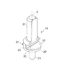
図面を参照すると、本発明に係るガスシリンダアクチュエータは、全般に参照符号10で示されている。
Referring to the drawings, a gas cylinder actuator according to the present invention is indicated generally by the
ガスシリンダアクチュエータ10は、
筒状容器11と、
ピストン・軸体15と、
筒状容器11の両端にそれぞれ設けられ、筒状容器11との間にシール部材を介して筒状容器11を封止する第1蓋体12及び第2蓋体13であって、ピストン・軸体15が通過する貫通孔14が設けられた第1蓋体12、及びガス充填路16が設けられた第2蓋体13と、
筒状容器11、第1蓋体12、第2蓋体13、及びピストン・軸体15によって形成される加圧ガス室17と
を備える。
The
A
A piston /
A
A
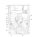
ガスシリンダアクチュエータ10の特徴は、第2蓋体13が、ガス充填路16の流動調整部材19と、当該流動調整部材19に対応して設けられるシール部材20とを収容する取付座18を有することにある。
A feature of the
流動調整部材19は、ピストン・軸体15の引き込み行程を規制する規制タブ21を備え、この規制タブ21は、ピストン・軸体15によって規制タブ21が押しつぶされた場合に、規制された破断または変形を引き起こす脆弱部23を有した本体部22から突設される。
The
具体的には、本発明の非限定的な例を用いてここで説明する実施形態において、取付座18は、加圧ガス室17内に開口しており、流動調整部材19は、ガス充填路16を流動調整部材19のための取付座18内に連通して第2蓋体13に形成された貫通孔25に挿入される心出し軸24を備える。
Specifically, in the embodiment described here using a non-limiting example of the present invention, the
この心出し軸24は、流動調整部材19の本体部22における規制タブ21とは反対側の位置で、本体部22から延設されている。
The
本実施形態において、規制タブ21は、ガスシリンダアクチュエータ10の対称軸X、即ち筒状容器11の中心軸線及びピストン・軸体15の中心軸線軸に平行な軸線方向に延設される。
In the present embodiment, the
具体的には、ガスシリンダアクチュエータ10の対称軸Xと同軸状に、規制タブ21が延設されている。
Specifically, the
流動調整部材19の本体部22は、心出し軸24に対し径方向に延設されて、シール部材20を押圧する環状面26を形成する。
The
このシール部材20は、例えば、シールリングからなり、流動調整部材19の取付座18の底面27と、流動調整部材19の本体部22の環状面26との間で押圧される。
The
流動調整部材19の本体部22は、実質的に円柱状をなしている。
The
脆弱部23は、ガスシリンダアクチュエータ10の対称軸Xと一致する流動調整部材19の中心軸線周りに、180°の角度範囲にわたって形成された径方向凹部28を備えることにより、行程超過となるピストン・軸体15の押し込みがあったときに、屈曲して規制タブ21の方に向けて変形するか、または破断する平坦部29を本体部22に形成する。
The
図3に分かり易く示しているように、行程超過となった場合、ピストン・軸体15が規制タブ21に衝突してこれを圧縮し、規制タブ21が部分的に変形して、流動調整部材19を下方に押すので、本体部22の脆弱部23が変形し、特に平坦部29に屈曲または破断が生じる。
As clearly shown in FIG. 3, when the stroke is exceeded, the piston /
本体部22の平坦部29がこのように屈曲または破断することにより、下方にある本体部22の環状面26は、少なくとも屈曲または破断した平坦部29において、もはやシールリングを圧縮するという役割を十分に果たすことができなくなり、シール部材20によるシールが行われなくなって、加圧ガス室17内で過剰圧力となったガスの逃げ道が形成される。
Since the
心出し軸24と、心出し軸24を収容する貫通孔25との間には、ガスの通過を可能とする遊びが設けられる。
Between the centering
上述のとおり、所期の意図及び目的に対する方策を本発明によって提供できることが、実際に判明した。 As mentioned above, it has actually been found that the present invention can provide a strategy for the intended intention and purpose.
即ち、本発明により、ピストン・軸体が行程超過となっても、安全で信頼性のある安全機構を備えたガスシリンダアクチュエータが提供される。 That is, according to the present invention, a gas cylinder actuator provided with a safe and reliable safety mechanism is provided even if the piston / shaft body exceeds the stroke.
更に、本発明を適用したガスシリンダアクチュエータは、流動調整部材が、ガスシリンダアクチュエータにおける他の部材に代わって、行程超過の状態となったピストン・軸体に起因して生じる力を吸収するように形成されて配置されると共に、そのような力を受けて変形し、加圧ガスの逃げ道を開放できるようになっていることで、安全機構が、第1蓋体、筒状容器、第2蓋体などのような重要な主要構成部品の変形または破損を引き起こすことがなくなる。 Furthermore, in the gas cylinder actuator to which the present invention is applied, the flow adjusting member absorbs the force generated by the piston / shaft body that has been in an over-stroke state instead of other members in the gas cylinder actuator. The safety mechanism is configured to be formed and arranged and deformed by receiving such a force so that the escape path of the pressurized gas can be opened. Thus, the safety mechanism includes the first lid, the cylindrical container, and the second lid. It will not cause deformation or breakage of important major components such as the body.
また、本発明を適用したガスシリンダアクチュエータは、安全機構を容易に装備して取り付けることが可能である。 The gas cylinder actuator to which the present invention is applied can be easily equipped with a safety mechanism.
上述した本発明は、様々な修正や変更が可能であり、それらはいずれも添付の特許請求の範囲内に含まれるものである。 Various modifications and changes can be made to the present invention described above, all of which are within the scope of the appended claims.
使用する部材及び素材、並びに大きさは、具体的な使用に適合するものである限り、必要に応じ、また技術水準に応じて任意に定めることができる。 The members and materials to be used, and the size can be arbitrarily determined as necessary and according to the technical level as long as they are suitable for specific use.
Claims (10)
筒状容器(11)と、
ピストン・軸体(15)と、
前記筒状容器(11)の両端にそれぞれ設けられ、前記筒状容器(11)との間にシール部材を介して前記筒状容器(11)を封止する第1蓋体(12)及び第2蓋体(13)であって、前記ピストン・軸体(15)が通過する貫通孔(14)が設けられた第1蓋体(12)、及びガス充填路(16)が設けられた第2蓋体(13)と、
前記筒状容器(11)、前記第1蓋体(12)、前記第2蓋体(13)、及び前記ピストン・軸体(15)によって形成される加圧ガス室(17)とを備え、
前記第2蓋体(13)は、前記ガス充填路(16)の流動調整部材(19)と、前記流動調整部材(19)に対応して設けられるシール部材(20)とを収容する取付座(18)を有し、
前記流動調整部材(19)は、前記ピストン・軸体(15)の引き込み行程を規制する規制タブ(21)を備え、
前記規制タブ(21)は、前記ピストン・軸体(15)によって前記規制タブ(21)が押しつぶされた場合に、規制された破断または変形を引き起こす脆弱部(23)を有した本体部(22)から突設される
ことを特徴とするガスシリンダアクチュエータ。 A gas cylinder actuator (10) with a safety mechanism,
A cylindrical container (11);
Piston and shaft (15),
A first lid (12) and a first lid (12) that are provided at both ends of the cylindrical container (11) and seal the cylindrical container (11) between the cylindrical container (11) and a sealing member. A first lid (12) provided with a through hole (14) through which the piston / shaft body (15) passes, and a gas filling passage (16). Two lids (13);
A pressurized gas chamber (17) formed by the cylindrical container (11), the first lid (12), the second lid (13), and the piston / shaft (15);
The second lid (13) is a mounting seat for accommodating the flow adjusting member (19) of the gas filling passage (16) and a seal member (20) provided corresponding to the flow adjusting member (19). (18)
The flow adjusting member (19) includes a regulation tab (21) that regulates a drawing stroke of the piston / shaft body (15),
The restriction tab (21) has a body portion (22) having a fragile portion (23) that causes a restricted breakage or deformation when the restriction tab (21) is crushed by the piston / shaft (15). The gas cylinder actuator is characterized in that it protrudes from the above.
前記流動調整部材(19)は、前記ガス充填路(16)を前記流動調整部材(19)のための前記取付座(18)内に連通して前記第2蓋体(13)に形成された貫通孔(25)に挿入される心出し軸(24)を備える
ことを特徴とする請求項1に記載のガスシリンダアクチュエータ。 The mounting seat (18) opens into the pressurized gas chamber (17),
The flow adjusting member (19) is formed in the second lid (13) by communicating the gas filling path (16) with the mounting seat (18) for the flow adjusting member (19). The gas cylinder actuator according to claim 1, further comprising a centering shaft (24) inserted into the through hole (25).
Applications Claiming Priority (2)
| Application Number | Priority Date | Filing Date | Title |
|---|---|---|---|
| ITUA2016A004635A ITUA20164635A1 (en) | 2016-06-24 | 2016-06-24 | GAS SPRING WITH SAFETY DEVICE |
| IT102016000065690 | 2016-06-24 |
Publications (2)
| Publication Number | Publication Date |
|---|---|
| JP2017227332A true JP2017227332A (en) | 2017-12-28 |
| JP6967888B2 JP6967888B2 (en) | 2021-11-17 |
Family
ID=57209784
Family Applications (1)
| Application Number | Title | Priority Date | Filing Date |
|---|---|---|---|
| JP2017123024A Active JP6967888B2 (en) | 2016-06-24 | 2017-06-23 | Gas cylinder actuator with safety mechanism |
Country Status (9)
| Country | Link |
|---|---|
| US (1) | US10619695B2 (en) |
| EP (1) | EP3260726B1 (en) |
| JP (1) | JP6967888B2 (en) |
| KR (1) | KR20180001486A (en) |
| CN (1) | CN107542721B (en) |
| BR (1) | BR102017013670A2 (en) |
| ES (1) | ES2719087T3 (en) |
| IT (1) | ITUA20164635A1 (en) |
| TR (1) | TR201904127T4 (en) |
Cited By (2)
| Publication number | Priority date | Publication date | Assignee | Title |
|---|---|---|---|---|
| JP2019076385A (en) * | 2017-10-24 | 2019-05-23 | 株式会社三共 | Game machine |
| US10428897B2 (en) * | 2015-06-26 | 2019-10-01 | Strömsholen AB | Compressible fluid device comprising safety device and method of protecting a compressible fluid device |
Families Citing this family (2)
| Publication number | Priority date | Publication date | Assignee | Title |
|---|---|---|---|---|
| GB2587317A (en) * | 2019-07-09 | 2021-03-31 | David Screation Lee | Lightweight hydraulic cylinder |
| EP4071378A1 (en) * | 2021-04-07 | 2022-10-12 | Special Springs S.r.l. | Gas spring |
Family Cites Families (11)
| Publication number | Priority date | Publication date | Assignee | Title |
|---|---|---|---|---|
| US5275387A (en) * | 1992-04-09 | 1994-01-04 | Power Components, Inc. | Gas spring |
| US5975507A (en) * | 1997-08-13 | 1999-11-02 | Diebolt International, Inc. | Gas spring with filler block |
| FR2778956B1 (en) * | 1998-05-22 | 2000-08-04 | Orflam Ind | GAS SPRING INCORPORATING A SAFETY MEMBER |
| ES1041675Y (en) * | 1998-12-11 | 1999-11-16 | Pariente Antonio Cabrerizo | SAFETY DEVICE FOR PNEUMATIC CYLINDERS. |
| SE517582C2 (en) | 1999-03-31 | 2002-06-25 | Berg Connectors Sweden Ab | socket |
| ITPD20070378A1 (en) * | 2007-11-13 | 2009-05-14 | Special Springs Srl | SAFETY DEVICE FOR GAS SPRINGS |
| IT1393971B1 (en) * | 2009-04-21 | 2012-05-17 | Special Springs Srl | GAS SPRING WITH SAFETY DEVICE FOR THE PISTON STEM CONTROLLED |
| EP3012480B1 (en) * | 2013-06-17 | 2017-05-31 | Azol-Gas, S. L. | Gas spring with controlled decompression |
| CN203421106U (en) * | 2013-08-31 | 2014-02-05 | 邵阳兴达精密机械制造有限公司 | Safety nitrogen spring |
| JP6595242B2 (en) * | 2014-07-31 | 2019-10-23 | スペシャル・スプリングス・ソシエタ・ア・レスポンサビリタ・リミタータ | Gas operated spring |
| CN204153041U (en) * | 2014-10-19 | 2015-02-11 | 北京洪树冶金机械厂 | One crosses stroke protection type nitrogen spring |
-
2016
- 2016-06-24 IT ITUA2016A004635A patent/ITUA20164635A1/en unknown
-
2017
- 2017-06-20 CN CN201710468807.1A patent/CN107542721B/en active Active
- 2017-06-22 ES ES17177338T patent/ES2719087T3/en active Active
- 2017-06-22 TR TR2019/04127T patent/TR201904127T4/en unknown
- 2017-06-22 EP EP17177338.5A patent/EP3260726B1/en active Active
- 2017-06-23 JP JP2017123024A patent/JP6967888B2/en active Active
- 2017-06-23 BR BR102017013670-1A patent/BR102017013670A2/en not_active Application Discontinuation
- 2017-06-23 US US15/631,552 patent/US10619695B2/en active Active
- 2017-06-23 KR KR1020170079605A patent/KR20180001486A/en not_active Application Discontinuation
Cited By (2)
| Publication number | Priority date | Publication date | Assignee | Title |
|---|---|---|---|---|
| US10428897B2 (en) * | 2015-06-26 | 2019-10-01 | Strömsholen AB | Compressible fluid device comprising safety device and method of protecting a compressible fluid device |
| JP2019076385A (en) * | 2017-10-24 | 2019-05-23 | 株式会社三共 | Game machine |
Also Published As
| Publication number | Publication date |
|---|---|
| EP3260726A1 (en) | 2017-12-27 |
| TR201904127T4 (en) | 2019-04-22 |
| JP6967888B2 (en) | 2021-11-17 |
| US20170370440A1 (en) | 2017-12-28 |
| US10619695B2 (en) | 2020-04-14 |
| ES2719087T3 (en) | 2019-07-08 |
| CN107542721B (en) | 2020-10-23 |
| ITUA20164635A1 (en) | 2017-12-24 |
| KR20180001486A (en) | 2018-01-04 |
| CN107542721A (en) | 2018-01-05 |
| BR102017013670A2 (en) | 2018-01-09 |
| EP3260726B1 (en) | 2019-01-02 |
Similar Documents
| Publication | Publication Date | Title |
|---|---|---|
| JP2017227332A (en) | Gas cylinder actuator with safety device | |
| JP6595242B2 (en) | Gas operated spring | |
| JP5558497B2 (en) | Gas cylinder actuator with safety device for over-stroke countermeasures | |
| US20130228069A1 (en) | Gas cylinder actuator with overtravel safety device | |
| JP2012524875A (en) | Gas cylinder actuator with a safety device that can control the protrusion of the piston stem | |
| ITPR20100064A1 (en) | MECHANICAL SAFETY VALVE FOR HIGH PRESSURES | |
| WO2009063003A1 (en) | Safety device for spring/damper units | |
| RU2675964C2 (en) | Pressure relief valve | |
| JP6346907B2 (en) | Overflow valve | |
| CN107110394B (en) | Valve actuating device with opening deceleration function | |
| KR20150021165A (en) | Hydro-pneumatic type relief valve | |
| EP3184847B1 (en) | Gas cylinder actuator with safety device | |
| KR20180074337A (en) | Accumulator | |
| KR20120024243A (en) | Cylinder loaded type closed safety valve | |
| JP2010540863A (en) | Hydropneumatic cylinder with controlled stop position | |
| KR20160042904A (en) | Actuating device and method for actuating a valve | |
| CN210769609U (en) | Rod cavity pressure reducing and load releasing valve of hydraulic rerailer oil cylinder | |
| EP3012480B1 (en) | Gas spring with controlled decompression | |
| US20190162209A1 (en) | Tensioning cylinder device | |
| JP6917705B2 (en) | Gas cylinder actuator with overstroke safety device | |
| KR102311467B1 (en) | Gas cylinder actuator with overtravel indicator device | |
| RU2575186C1 (en) | Safety membrane device | |
| KR101147816B1 (en) | Cylinder Loaded Type Opened Safety Valve | |
| JP2012026541A (en) | Safety mechanism of supply and discharge valve | |
| JP2015161333A (en) | shock absorber |
Legal Events
| Date | Code | Title | Description |
|---|---|---|---|
| A621 | Written request for application examination |
Free format text: JAPANESE INTERMEDIATE CODE: A621 Effective date: 20200528 |
|
| A977 | Report on retrieval |
Free format text: JAPANESE INTERMEDIATE CODE: A971007 Effective date: 20210325 |
|
| A131 | Notification of reasons for refusal |
Free format text: JAPANESE INTERMEDIATE CODE: A131 Effective date: 20210331 |
|
| A521 | Request for written amendment filed |
Free format text: JAPANESE INTERMEDIATE CODE: A523 Effective date: 20210607 |
|
| TRDD | Decision of grant or rejection written | ||
| A01 | Written decision to grant a patent or to grant a registration (utility model) |
Free format text: JAPANESE INTERMEDIATE CODE: A01 Effective date: 20211013 |
|
| A61 | First payment of annual fees (during grant procedure) |
Free format text: JAPANESE INTERMEDIATE CODE: A61 Effective date: 20211026 |
|
| R150 | Certificate of patent or registration of utility model |
Ref document number: 6967888 Country of ref document: JP Free format text: JAPANESE INTERMEDIATE CODE: R150 |
|
| R250 | Receipt of annual fees |
Free format text: JAPANESE INTERMEDIATE CODE: R250 |