JP2017227295A - Vibration control device - Google Patents
Vibration control device Download PDFInfo
- Publication number
- JP2017227295A JP2017227295A JP2016124915A JP2016124915A JP2017227295A JP 2017227295 A JP2017227295 A JP 2017227295A JP 2016124915 A JP2016124915 A JP 2016124915A JP 2016124915 A JP2016124915 A JP 2016124915A JP 2017227295 A JP2017227295 A JP 2017227295A
- Authority
- JP
- Japan
- Prior art keywords
- liquid
- liquid chamber
- barrier
- communication portion
- pores
- Prior art date
- Legal status (The legal status is an assumption and is not a legal conclusion. Google has not performed a legal analysis and makes no representation as to the accuracy of the status listed.)
- Granted
Links
- 239000007788 liquid Substances 0.000 claims abstract description 188
- 239000011148 porous material Substances 0.000 claims abstract description 72
- 230000004888 barrier function Effects 0.000 claims abstract description 43
- 230000000149 penetrating effect Effects 0.000 claims abstract description 4
- 238000005192 partition Methods 0.000 claims description 50
- 230000015556 catabolic process Effects 0.000 abstract 1
- 230000000593 degrading effect Effects 0.000 abstract 1
- 230000002093 peripheral effect Effects 0.000 description 22
- 230000007423 decrease Effects 0.000 description 9
- 230000002159 abnormal effect Effects 0.000 description 5
- 238000002955 isolation Methods 0.000 description 3
- 239000000470 constituent Substances 0.000 description 2
- 239000012530 fluid Substances 0.000 description 2
- 238000004519 manufacturing process Methods 0.000 description 2
- 230000004323 axial length Effects 0.000 description 1
- 230000005540 biological transmission Effects 0.000 description 1
- 230000015572 biosynthetic process Effects 0.000 description 1
- 230000006835 compression Effects 0.000 description 1
- 238000007906 compression Methods 0.000 description 1
- 238000010276 construction Methods 0.000 description 1
- 238000006073 displacement reaction Methods 0.000 description 1
- 239000013013 elastic material Substances 0.000 description 1
- 238000012986 modification Methods 0.000 description 1
- 230000004048 modification Effects 0.000 description 1
- 229920005989 resin Polymers 0.000 description 1
- 239000011347 resin Substances 0.000 description 1
- 239000000725 suspension Substances 0.000 description 1
- 229920003002 synthetic resin Polymers 0.000 description 1
- 239000000057 synthetic resin Substances 0.000 description 1
Images


Classifications
-
- F—MECHANICAL ENGINEERING; LIGHTING; HEATING; WEAPONS; BLASTING
- F16—ENGINEERING ELEMENTS AND UNITS; GENERAL MEASURES FOR PRODUCING AND MAINTAINING EFFECTIVE FUNCTIONING OF MACHINES OR INSTALLATIONS; THERMAL INSULATION IN GENERAL
- F16F—SPRINGS; SHOCK-ABSORBERS; MEANS FOR DAMPING VIBRATION
- F16F13/00—Units comprising springs of the non-fluid type as well as vibration-dampers, shock-absorbers, or fluid springs
- F16F13/04—Units comprising springs of the non-fluid type as well as vibration-dampers, shock-absorbers, or fluid springs comprising both a plastics spring and a damper, e.g. a friction damper
- F16F13/06—Units comprising springs of the non-fluid type as well as vibration-dampers, shock-absorbers, or fluid springs comprising both a plastics spring and a damper, e.g. a friction damper the damper being a fluid damper, e.g. the plastics spring not forming a part of the wall of the fluid chamber of the damper
- F16F13/08—Units comprising springs of the non-fluid type as well as vibration-dampers, shock-absorbers, or fluid springs comprising both a plastics spring and a damper, e.g. a friction damper the damper being a fluid damper, e.g. the plastics spring not forming a part of the wall of the fluid chamber of the damper the plastics spring forming at least a part of the wall of the fluid chamber of the damper
- F16F13/10—Units comprising springs of the non-fluid type as well as vibration-dampers, shock-absorbers, or fluid springs comprising both a plastics spring and a damper, e.g. a friction damper the damper being a fluid damper, e.g. the plastics spring not forming a part of the wall of the fluid chamber of the damper the plastics spring forming at least a part of the wall of the fluid chamber of the damper the wall being at least in part formed by a flexible membrane or the like
- F16F13/105—Units comprising springs of the non-fluid type as well as vibration-dampers, shock-absorbers, or fluid springs comprising both a plastics spring and a damper, e.g. a friction damper the damper being a fluid damper, e.g. the plastics spring not forming a part of the wall of the fluid chamber of the damper the plastics spring forming at least a part of the wall of the fluid chamber of the damper the wall being at least in part formed by a flexible membrane or the like characterised by features of partitions between two working chambers
- F16F13/107—Passage design between working chambers
-
- B—PERFORMING OPERATIONS; TRANSPORTING
- B60—VEHICLES IN GENERAL
- B60K—ARRANGEMENT OR MOUNTING OF PROPULSION UNITS OR OF TRANSMISSIONS IN VEHICLES; ARRANGEMENT OR MOUNTING OF PLURAL DIVERSE PRIME-MOVERS IN VEHICLES; AUXILIARY DRIVES FOR VEHICLES; INSTRUMENTATION OR DASHBOARDS FOR VEHICLES; ARRANGEMENTS IN CONNECTION WITH COOLING, AIR INTAKE, GAS EXHAUST OR FUEL SUPPLY OF PROPULSION UNITS IN VEHICLES
- B60K5/00—Arrangement or mounting of internal-combustion or jet-propulsion units
- B60K5/12—Arrangement of engine supports
- B60K5/1208—Resilient supports
-
- F—MECHANICAL ENGINEERING; LIGHTING; HEATING; WEAPONS; BLASTING
- F16—ENGINEERING ELEMENTS AND UNITS; GENERAL MEASURES FOR PRODUCING AND MAINTAINING EFFECTIVE FUNCTIONING OF MACHINES OR INSTALLATIONS; THERMAL INSULATION IN GENERAL
- F16F—SPRINGS; SHOCK-ABSORBERS; MEANS FOR DAMPING VIBRATION
- F16F2224/00—Materials; Material properties
- F16F2224/02—Materials; Material properties solids
- F16F2224/025—Elastomers
Landscapes
- Engineering & Computer Science (AREA)
- General Engineering & Computer Science (AREA)
- Mechanical Engineering (AREA)
- Chemical & Material Sciences (AREA)
- Combustion & Propulsion (AREA)
- Transportation (AREA)
- Combined Devices Of Dampers And Springs (AREA)
Abstract
Description
本発明は、例えば自動車や産業機械等に適用され、エンジン等の振動発生部の振動を吸収および減衰する防振装置に関する。 The present invention relates to a vibration isolator that is applied to, for example, automobiles and industrial machines and absorbs and attenuates vibrations of a vibration generating unit such as an engine.
この種の防振装置として、従来、振動発生部および振動受部のうちの一方に連結される筒状の第1取付け部材、および他方に連結される第2取付け部材と、これらの両取付け部材を連結する弾性体と、液体が封入された第1取付け部材内の液室を主液室と副液室とに区画する仕切り部材と、を備える構成が知られている。仕切り部材には、主液室と副液室とを連通する制限通路が形成されている。この防振装置では、振動入力時に、両取付け部材が弾性体を弾性変形させながら相対的に変位し、主液室の液圧を変動させて制限通路に液体を流通させることで、振動を吸収および減衰している。 Conventionally, as this type of vibration isolator, a cylindrical first attachment member connected to one of the vibration generating portion and the vibration receiving portion, a second attachment member connected to the other, and both of these attachment members There is known a configuration including an elastic body that connects the two and a partition member that divides a liquid chamber in a first mounting member in which a liquid is sealed into a main liquid chamber and a sub liquid chamber. The partition member is formed with a restriction passage that communicates the main liquid chamber and the sub liquid chamber. In this vibration isolator, at the time of vibration input, both attachment members are relatively displaced while elastically deforming the elastic body, and the vibration is absorbed by changing the liquid pressure in the main liquid chamber and allowing the liquid to flow through the restricted passage. And is decaying.
ところで、この防振装置では、例えば路面の凹凸等から大きな荷重(振動)が入力され、主液室の液圧が急激に上昇した後、弾性体のリバウンド等によって逆方向に荷重が入力されたときに、主液室が急激に負圧化されることがある。すると、この急激な負圧化により液中に多数の気泡が生成されるキャビテーションが発生し、さらに生成した気泡が崩壊するキャビテーション崩壊に起因して、異音が生じることがある。
そこで、例えば下記特許文献1に示される防振装置のように、制限通路内に弁体を設けることで、大きな振幅の振動が入力されたときであっても、主液室の負圧化を抑制する構成が知られている。
By the way, in this vibration isolator, for example, a large load (vibration) is input from the unevenness of the road surface, etc., and the load is input in the reverse direction due to the rebound of the elastic body after the fluid pressure in the main fluid chamber suddenly increases. Sometimes, the main liquid chamber is suddenly depressurized. Then, cavitation in which a large number of bubbles are generated in the liquid due to this sudden negative pressure is generated, and abnormal noise may be generated due to cavitation collapse in which the generated bubbles collapse.
Therefore, for example, by providing a valve body in the restriction passage as in the vibration isolator shown in Patent Document 1 below, the main liquid chamber can be negatively pressured even when large amplitude vibration is input. Suppressing configurations are known.
しかしながら、前記従来の防振装置では、弁体が設けられることで構造が複雑になり、弁体のチューニングも必要となるため、製造コストが増加するといった課題がある。また、弁体を設けることで設計自由度が低下し、結果として防振特性が低下するおそれもある。 However, in the conventional vibration isolator, since the structure is complicated by providing the valve body, and tuning of the valve body is necessary, there is a problem that the manufacturing cost increases. Further, the provision of the valve body reduces the degree of freedom in design, and as a result, the vibration isolation characteristics may be reduced.
本発明は前記事情に鑑みてなされたもので、簡易な構造で防振特性を低下させることなく、キャビテーション崩壊に起因する異音の発生を抑えることができる防振装置を提供することを目的とする。 The present invention has been made in view of the above circumstances, and an object thereof is to provide a vibration isolator capable of suppressing the occurrence of abnormal noise due to cavitation collapse without reducing the vibration isolation characteristics with a simple structure. To do.
前記課題を解決するために、本発明は以下の手段を提案している。
本発明に係る防振装置は、振動発生部および振動受部のうちのいずれか一方に連結される筒状の第1取付け部材、および他方に連結される第2取付け部材と、これら両取付け部材を弾性的に連結する弾性体と、液体が封入された前記第1取付け部材内の液室を第1液室と第2液室とに区画する仕切り部材と、を備えるとともに、前記仕切り部材に、前記第1液室と前記第2液室とを連通する制限通路が形成された液体封入型の防振装置であって、前記制限通路は、前記第1液室に面する第1障壁に形成されるとともに、前記第1液室に開口する第1連通部、前記第2液室に面する第2障壁に形成されるとともに、前記第2液室に開口する第2連通部、および前記第1連通部と前記第2連通部とを連通する本体流路を備え、前記第1連通部および前記第2連通部のうちの少なくとも一方は、前記第1障壁または前記第2障壁を貫通する複数の細孔を備え、前記本体流路において、前記第1連通部および前記第2連通部のうちの少なくとも一方との接続部分には、前記第1連通部および前記第2連通部のうちの他方側からの液体の流速に応じて液体の旋回流を形成し、この液体を、前記細孔を通して流出させる渦室が配置されている。
In order to solve the above problems, the present invention proposes the following means.
A vibration isolator according to the present invention includes a cylindrical first mounting member connected to one of a vibration generating unit and a vibration receiving unit, a second mounting member connected to the other, and both the mounting members. And a partition member that partitions the liquid chamber in the first mounting member in which the liquid is sealed into a first liquid chamber and a second liquid chamber, and the partition member A liquid-filled vibration isolator having a restriction passage communicating the first liquid chamber and the second liquid chamber, wherein the restriction passage is a first barrier facing the first liquid chamber. A first communication portion formed in the first liquid chamber, a second communication portion formed in the second barrier facing the second liquid chamber, and opened in the second liquid chamber; and A main body flow path communicating the first communication portion and the second communication portion; At least one of the second communication portions includes a plurality of pores penetrating the first barrier or the second barrier, and in the main body channel, of the first communication portion and the second communication portion. A swirling flow of a liquid is formed at a connection portion with at least one of the first communication portion and the second communication portion according to the flow velocity of the liquid from the other side of the first communication portion and the second communication portion. A vortex chamber is provided for discharge.
本発明によれば、振動入力時に、両取付け部材が弾性体を弾性変形させながら相対的に変位して第1液室の液圧が変動し、液体が制限通路を通って第1液室と第2液室との間を流通しようとする。このとき液体は、第1連通部および第2連通部のうちの一方を通して本体流路に流入した後、第1連通部および第2連通部のうちの他方を通して本体流路から流出する。
ここで、防振装置に大きな荷重(振動)が入力された場合であって、第1連通部および第2連通部のうちの一方との接続部分に設けられた渦室に、第1連通部および第2連通部のうちの他方側から液体が流入されるときに、その液体の流速が十分に高く、渦室内で液体の旋回流が形成されると、例えば、この旋回流を形成することによるエネルギー損失や、液体と渦室の壁面との間の摩擦によるエネルギー損失などを起因として、液体の圧力損失を高めることができる。さらにその液体が、第1連通部または第2連通部に備えられた複数の細孔を通して流出するときには、これらの細孔が形成された第1障壁または第2障壁により液体が圧力損失させられながら液体が細孔を流通し、複数の細孔を流通する液体の流速の上昇を抑えることができる。しかも、液体が、単一の細孔ではなく複数の細孔を流通するので、液体を複数に分岐させて流通させることが可能になり、個々の細孔を通過した液体の流速を低減させることができる。これにより、細孔を通過して第1液室または第2液室に流入した液体と、第1液室内または第2液室内の液体と、の間で生じる流速差を小さく抑え、流速差に起因する渦の発生、およびこの渦に起因する気泡の発生を抑えることができる。さらに、仮に気泡が発生したとしても、細孔が複数配置されているので、発生した気泡同士を離間させることが可能になり、気泡が合流して成長するのを抑えて気泡を細かく分散させた状態に維持し易くすることができる。また、仮に気泡が第1液室や第2液室ではなく制限通路内で発生しても、気泡が細孔を通過する際に、その気泡を細かい気泡に分割させ、その後、分散させることができる。
以上のように、気泡の発生そのものを抑えることができる上、たとえ気泡が発生したとしても、気泡を細かく分散させた状態に維持し易くすることができるので、気泡が崩壊するキャビテーション崩壊が生じても、発生する異音を小さく抑えることができる。
According to the present invention, at the time of vibration input, both the attachment members are relatively displaced while elastically deforming the elastic body, the liquid pressure in the first liquid chamber fluctuates, and the liquid passes through the restriction passage and the first liquid chamber. It tries to circulate between the second liquid chamber. At this time, the liquid flows into the main body flow path through one of the first communication section and the second communication section, and then flows out from the main flow path through the other of the first communication section and the second communication section.
Here, when a large load (vibration) is input to the vibration isolator, the first communicating portion is provided in the vortex chamber provided at the connecting portion with one of the first communicating portion and the second communicating portion. When the liquid is introduced from the other side of the second communication portion, the flow velocity of the liquid is sufficiently high, and if a swirl flow of the liquid is formed in the vortex chamber, for example, the swirl flow is formed. It is possible to increase the pressure loss of the liquid due to the energy loss due to or the energy loss due to the friction between the liquid and the wall of the vortex chamber. Further, when the liquid flows out through the plurality of pores provided in the first communication portion or the second communication portion, the liquid is pressure-lossed by the first barrier or the second barrier in which these pores are formed. The liquid flows through the pores, and an increase in the flow rate of the liquid flowing through the plurality of pores can be suppressed. In addition, since the liquid flows through a plurality of pores instead of a single pore, it is possible to divide the liquid into a plurality of channels and reduce the flow rate of the liquid that has passed through the individual pores. Can do. As a result, the flow rate difference between the liquid that has passed through the pores and flowed into the first liquid chamber or the second liquid chamber and the liquid in the first liquid chamber or the second liquid chamber is suppressed to a small value. It is possible to suppress the generation of vortices caused and the generation of bubbles due to the vortices. Furthermore, even if bubbles are generated, since a plurality of pores are arranged, the generated bubbles can be separated from each other, and the bubbles are dispersed finely while suppressing the bubbles from joining and growing. The state can be easily maintained. Even if bubbles are generated in the restricted passage instead of the first liquid chamber or the second liquid chamber, the bubbles can be divided into fine bubbles and then dispersed when the bubbles pass through the pores. it can.
As described above, the generation of bubbles itself can be suppressed, and even if bubbles are generated, the bubbles can be easily maintained in a finely dispersed state. However, it is possible to suppress the generated abnormal noise.
前記複数の細孔は、前記第1障壁または前記第2障壁に、前記渦室で形成される液体の旋回流の旋回方向に沿って配置され、前記第1障壁または前記第2障壁における所定面積当たりに占める、前記細孔における最小横断面の開口面積または投影面積の割合が、前記旋回方向の後側から前側に向かうに従い漸次、大きくなっていてもよい。 The plurality of pores are arranged in the first barrier or the second barrier along a swirling direction of a swirling flow of liquid formed in the vortex chamber, and have a predetermined area in the first barrier or the second barrier. The ratio of the opening area or projected area of the minimum cross section in the pores that occupies the hit may gradually increase from the rear side to the front side in the turning direction.
渦室内で液体の旋回流が形成されると、液体の圧力損失が生じるため、液体の流速は、旋回方向の後側から前側に向かうに従い漸次、低くなる。つまり、旋回流を形成する液体では、旋回方向の後側に位置するほど、防振装置の平面視において渦室の中心軸線に直交する方向(以下、「旋回径方向」という。)の外側に向かう慣性力が大きい。
ここで前記割合が、旋回方向の後側から前側に向かうに従い漸次、大きくなっていて、液体の流速が高い旋回方向の後側において、前記割合を抑えることができる。したがって、旋回流を形成する液体が、その液体に作用する慣性力を起因として、複数の細孔のうち、旋回方向の後側に位置する細孔を通して渦室から流出することを抑制し、旋回方向の前側に位置する細孔からも液体を流出させることができる。これにより、旋回方向の後側に位置する細孔から大量の液体が局所的に高速で流出するのを抑制することが可能になり、複数の細孔全体から、流速のばらつきを抑えつつ液体を流出させ、気泡の発生を効果的に抑えることができる。
When a swirl flow of the liquid is formed in the vortex chamber, a pressure loss of the liquid occurs, so that the liquid flow rate gradually decreases as it goes from the rear side to the front side in the swirl direction. In other words, in the liquid forming the swirl flow, the further the position is on the rear side of the swirl direction, the more outward in the direction perpendicular to the central axis of the vortex chamber (hereinafter referred to as “swirling radial direction”) in plan view of the vibration isolator. The inertial force heading is great
Here, the ratio is gradually increased from the rear side to the front side in the turning direction, and the ratio can be suppressed on the rear side in the turning direction in which the liquid flow rate is high. Therefore, the liquid forming the swirling flow is prevented from flowing out of the vortex chamber through the fine pores located on the rear side in the swirling direction among the plurality of fine pores due to the inertial force acting on the liquid, and swirling. The liquid can also flow out from the pores located on the front side in the direction. This makes it possible to prevent a large amount of liquid from locally flowing out from the pores located on the rear side in the swirl direction at a high speed, and from the entire plurality of pores, the liquid can be discharged while suppressing variations in flow velocity. Outflow can effectively suppress the generation of bubbles.
本発明によれば、簡易な構造で防振特性を低下させることなく、キャビテーション崩壊に起因する異音の発生を抑えることができる。 According to the present invention, it is possible to suppress the generation of abnormal noise caused by cavitation collapse without reducing the vibration isolation characteristics with a simple structure.
以下、本発明に係る防振装置の実施の形態について、図1から図5に基づいて説明する。
図1に示すように、防振装置10は、振動発生部および振動受部のいずれか一方に連結される筒状の第1取付け部材11と、振動発生部および振動受部のいずれか他方に連結される第2取付け部材12と、これらの第1取付け部材11、第2取付け部材12同士を弾性的に連結する弾性体13と、第1取付け部材11内を後述する主液室14(第1液室)と副液室15(第2液室)とに区画する仕切り部材16と、を備える液体封入型の防振装置である。
Hereinafter, an embodiment of a vibration isolator according to the present invention will be described with reference to FIGS. 1 to 5.
As shown in FIG. 1, the
以下、第1取付け部材11の中心軸線を軸心Oといい、軸心Oに沿う方向を軸方向という。また、軸方向に沿う第2取付け部材12側を上側、仕切り部材16側を下側という。また、防振装置10を軸方向から見た平面視において、軸心O周りに周回する方向を周方向という。
なお、第1取付け部材11、第2取付け部材12、および弾性体13はそれぞれ、平面視した状態で円形状若しくは円環状に形成されるとともに、軸心Oと同軸に配置されている。
Hereinafter, the central axis of the first mounting
The first mounting
この防振装置10が例えば自動車に装着される場合、第2取付け部材12が振動発生部としてのエンジンに連結され、第1取付け部材11が振動受部としての車体に連結される。これにより、エンジンの振動が車体に伝達することが抑えられる。
When the
第2取付け部材12は、軸方向に延在する柱状部材であり、下端部が半球面状に形成されるとともに、この半球面状の下端部より上方に鍔部12aを有している。この第2取付け部材12の上部には、その上端面から下方に向かって延びるねじ孔12bが穿設され、このねじ孔12bにエンジン側の取付け具となるボルト(図示せず)が螺合されるようになっている。また、この第2取付け部材12は、弾性体13を介して、第1取付け部材11の上端開口部側に配置されている。
The second mounting
弾性体13は、第1取付け部材11の上端開口部と第2取付け部材12の下端側外周面とにそれぞれ加硫接着されて、これらの間に介在させられたゴム体であって、第1取付け部材11の上端開口部を上側から閉塞している。この弾性体13は、その上端部が第2取付け部材12の鍔部12aに当接することで、第2取付け部材12に充分に密着し、該第2取付け部材12の変位により良好に追従するようになっている。また、弾性体13の下端部には、第1取付け部材11の内周面と下端開口縁の一部とを液密に被覆するゴム膜17が一体形成されている。なお、弾性体13としては、ゴム以外にも合成樹脂等からなる弾性体を用いることも可能である。
The
第1取付け部材11は、下端部にフランジ18を有する円筒状に形成され、フランジ18を介して振動受部としての車体等に連結される。この第1取付け部材11の内部のうち、弾性体13より下方に位置する部分が、液室19となっている。本実施形態では、第1取付け部材11の下端部内に仕切り部材16が設けられ、さらにこの仕切り部材16の下方にダイヤフラム20が設けられている。
The
ダイヤフラム20は、ゴムや軟質樹脂等の弾性材料からなり、有底円筒状に形成されている。ダイヤフラム20の上端部は、仕切り部材16と、仕切り部材16より下方に位置するリング状の保持具21と、によって軸方向に挟まれている。仕切り部材16には、その外周にフランジ部22が形成されており、このフランジ部22の下面に前記保持具21の上面が当接している。フランジ部22は、仕切り部材16の外周面の下端に設けられている。フランジ部22の内周部の上面は、ゴム膜17の下端部に液密に当接している。
The
このような構成のもとに、第1取付け部材11の下端開口縁に、仕切り部材16のフランジ部22、および保持具21が下方に向けてこの順に配置され、ねじ23によって固定されることにより、ダイヤフラム20は仕切り部材16を介して第1取付け部材11の下端開口部に取り付けられている。なお、ダイヤフラム20は、本実施形態ではその底部が、外周側で深く中央部で浅い形状になっている。ただし、ダイヤフラム20の形状としては、このような形状以外にも、従来公知の種々の形状を採用することができる。
Under such a configuration, the flange portion 22 of the
そして、このように第1取付け部材11に仕切り部材16を介してダイヤフラム20が取り付けられたことにより、前記したように第1取付け部材11内に液室19が形成されている。液室19は、第1取付け部材11内、すなわち平面視して第1取付け部材11の内側に配設されたもので、弾性体13とダイヤフラム20とにより液密に封止された密閉空間となっている。そして、この液室19には、液体Lが封入(充填)されている。
As described above, the
液室19は、仕切り部材16によって主液室14と副液室15とに区画されている。主液室14は、弾性体13の下面13aを壁面の一部として形成されたもので、この弾性体13と第1取付け部材11の内周面を液密に覆うゴム膜17と仕切り部材16とによって囲まれた空間であり、弾性体13の変形によって内容積が変化する。副液室15は、ダイヤフラム20と仕切り部材16とによって囲まれた空間であり、ダイヤフラム20の変形によって内容積が変化する。このような構成からなる防振装置10は、主液室14が鉛直方向上側に位置し、副液室15が鉛直方向下側に位置するように取り付けられて用いられる、圧縮式の装置である。
The
仕切り部材16の外周面は、ゴム膜17を介して第1取付け部材11内に嵌合されており、これにより、ゴム膜17と仕切り部材16との間が液密に閉塞されている。
仕切り部材16の上面には、凹部31が形成されている。凹部31は、軸心Oと同軸に配置されている。凹部31は、仕切り部材16を上方から見た上面視において円形状に形成されている。凹部31は、仕切り部材16に、環状の外周部32aと、外周部32aの内部を閉塞する板状の中央部32bと、を形成する。外周部32aは、凹部31の側面と、仕切り部材16の外周面と、の間に形成される。中央部32bは、凹部31の底面と、仕切り部材16の下面と、の間に形成され、外周部32aよりも軸方向に小さい(薄い)。
The outer peripheral surface of the
A
仕切り部材16には、主液室14と副液室15とを連通する制限通路24が設けられている。制限通路24は、仕切り部材16内に配置された本体流路25と、本体流路25と主液室14とを連通する第1連通部26と、本体流路25と副液室15とを連通する第2連通部27と、を備えている。
The
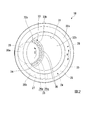
図2に示すように、本体流路25は、整流路28と、渦室29と、を備えている。整流路28は、仕切り部材16の外周面に周溝状に形成されている。整流路28は、仕切り部材16の外周面の少なくとも半周以上にわたって延びている。整流路28は、前記外周部32aに形成されている。整流路28では、制限通路24の流路方向Rが周方向となっている。
As shown in FIG. 2, the main
渦室29は、整流路28の周方向における2つの端部のうち、第1端部28aに設けられている。第1端部28aは、整流路28における渦室29との接続部分となっている。図4に示すように、第1端部28aの流路断面積は、流路方向Rに沿って第2連通部27から離間するに従い、小さくなっている。第1端部28aは、流路方向Rに沿って第2連通部27から離間するに従い、軸方向に小さくなっている。
The
図2に示すように、渦室29は、前記外周部32aおよび前記中央部32bにわたって設けられている。渦室29は、前記上面視において円形状に形成されている。渦室29の内周面は、前記上面視において渦室29の外周縁を形成している。渦室29の直径は、仕切り部材16の直径よりも小さく、渦室29の中心軸線は、軸心Oに対して偏心している。前記上面視において、渦室29の外周縁は、仕切り部材16の外周面に内接している。
As shown in FIG. 2, the
渦室29は、整流路28からの液体Lの流速に応じて液体Lの旋回流を形成する。渦室29内に流入する液体Lの流速が低いときには、渦室29内での液体Lの旋回が抑制されるものの、液体Lの流速が高いときには、渦室29内で液体Lの旋回流が形成される。旋回流は、渦室29の中心軸線回りに沿う方向に旋回する。つまり、渦室29で形成される液体Lの旋回流の旋回方向Tは、防振装置10を軸方向から見た平面視において、渦室29の中心軸線回りに沿う方向となる。
旋回方向Tに沿う前側は、前記上面視において反時計回り側となり、旋回方向Tに沿う後側は、前記上面視において時計回り側となる。なお以下では、防振装置10を軸方向から見た平面視において、渦室29の中心軸線に直交する方向を旋回径方向という。
The
The front side along the turning direction T is the counterclockwise side in the top view, and the rear side along the turning direction T is the clockwise side in the top view. In the following, the direction orthogonal to the central axis of the
図5に示すように、凹部31の底面には、溝部33が形成されている。溝部33は、旋回方向Tに沿って延びている。溝部33は、前記上面視において円弧状に形成されている。溝部33は、前記上面視において、渦室29の外周縁に沿って配置されている。前記上面視において、溝部33の両端部は、凹部31の側面に到達していて、溝部33は、凹部31の底面を2つの領域に区画している。
As shown in FIG. 5, a
図1および図5に示すように、溝部33の側面のうち、旋回径方向の外側を向く第1側面33aは、軸方向に平行に延びている。溝部33の側面のうち、旋回径方向の内側を向く第2側面33bは、傾斜面33cと、水平面33dと、鉛直面33eと、を備えている。傾斜面33c、水平面33dおよび鉛直面33eは、上方から下方に向けてこの順に設けられている。傾斜面33cは、上方から下方に向かうに従い漸次、旋回径方向の内側に向けて延びている。水平面33dは、傾斜面33cの下端部から旋回径方向の内側に向けて延びている。鉛直面33eは、水平面33dの旋回径方向の内側の端部から下方に向けて延びている。溝部33の底面は、渦室29の下面と面一に配置されている。
As shown in FIGS. 1 and 5, among the side surfaces of the
図5に示すように、仕切り部材16は、主液室14に面する第1障壁34と、副液室15に面する第2障壁35と、を備えている。第1障壁34は、仕切り部材16のうち、渦室29の内周面と、第1側面33aと、の間に位置する部分によって形成されている。第1障壁34は、旋回方向Tに沿って延びている。第2障壁35は、仕切り部材16のうち、整流路28の内面と、仕切り部材16の下面と、の間に位置する部分によって形成されている。第2障壁35は、流路方向Rに沿って延びている。
As shown in FIG. 5, the
第1連通部26は、第1障壁34に形成され、主液室14に開口している。第2連通部27は、第2障壁35に形成され、副液室15に開口している。
第1連通部26および第2連通部27のうちの少なくとも一方は、第1障壁34または第2障壁35を貫通する複数の細孔26aを備えている。本実施形態では、第1連通部26が、第1障壁34を貫通する複数の細孔26aを備えている。
The
At least one of the
複数の細孔26aは、第1障壁34に旋回方向Tに沿って配置されている。複数の細孔26aは、旋回方向Tに間隔をあけて複数配置されている。細孔26aは、第1障壁34を旋回径方向に貫通している。複数の細孔26aの主液室14に向けた開口部はいずれも、旋回径方向の外側から見た正面視において、軸方向に延びる長方形状に形成されている。細孔26aの下端部は、渦室29の下面(溝部33の底面)上に位置している。複数の細孔26aの流路断面積は、各細孔26aの流路長さ方向(図示の例では、旋回径方向)の内側から外側に向かうに従い漸次、大きくなっている。
The plurality of
第1障壁34における所定面積当たりに占める、細孔26aにおける最小横断面の開口面積または投影面積の割合は、旋回方向Tの後側から前側に向かうに従い漸次、大きくなっている。なお「投影面積」とは、第1障壁34における主液室14内に位置する面への、細孔26aの最小横断面の中央を通る細孔中心線が延びる方向に向けた投影面積をいう。本実施形態における「投影面積」とは、細孔26aの最小横断面の第1側面33aへの旋回径方向(流路長さ方向)への投影面積をいう。
本実施形態では、複数の細孔26aの周方向の幅は、それぞれ互いに同等となっている。複数の細孔26aは、それぞれ周方向に同等の間隔をあけて配置されている。そして、複数の細孔26aの軸方向の長さは、旋回方向Tの後側から前側に向かうに従い漸次、大きくなっている。これにより、前記割合が、旋回方向Tの後側から前側に向かうに従い漸次、大きくなっている。
The ratio of the opening area or projected area of the minimum cross section in the
In the present embodiment, the circumferential widths of the plurality of
なお図示の例では、第1側面33aのうち、細孔26aを回避した部分には、第1側面33aと第2側面33bとを接続するブリッジ部36が設けられている。ブリッジ部36の下面は、溝部33の底面に固定され、ブリッジ部36の上面は、水平面33dと面一に形成されている。
In the illustrated example, a
第2連通部27は、第2障壁35を軸方向に貫通する。第2連通部27は、流路方向Rに長い矩形状に形成されている。第2連通部27は、整流路28の第2端部28bに開口する。
前記制限通路24では、本体流路25が、第1連通部26と第2連通部27とを連通している。そして渦室29は、本体流路25において、第1連通部26および第2連通部27のうちの少なくとも一方である第1連通部26との接続部分に形成されている。渦室29は、第1連通部26および第2連通部27のうちの他方側である第2連通部27側からの液体Lの流速に応じて液体Lの旋回流を形成し、この液体Lを、細孔26aを通して流出させる。
The
In the
このような構成からなる防振装置10では、振動入力時に、両取付け部材11、12が弾性体13を弾性変形させながら相対的に変位する。すると、主液室14の液圧が変動し、主液室14内の液体Lが制限通路24を通って副液室15に流入し、また、副液室15内の液体Lが制限通路24を通って主液室14に流入する。すなわち、副液室15内の液体Lの一部が主液室14に戻る。
In the
本実施形態に係る防振装置10によれば、防振装置10に大きな荷重(振動)が入力された場合であって、渦室29に、第2連通部27側から液体Lが流入されるときに、その液体Lの流速が十分に高く、渦室29内で液体Lの旋回流が形成されると、例えば、この旋回流を形成することによるエネルギー損失や、液体Lと渦室29の壁面との間の摩擦によるエネルギー損失などを起因として、液体Lの圧力損失を高めることができる。さらにその液体Lが、複数の細孔26aを通して流出するときには、これらの細孔26aが形成された第1障壁34により液体Lが圧力損失させられながら液体Lが細孔26aを流通し、複数の細孔26aを流通する液体Lの流速の上昇を抑えることができる。しかも、液体Lが、単一の細孔26aではなく複数の細孔26aを流通するので、液体Lを複数に分岐させて流通させることが可能になり、個々の細孔26aを通過した液体Lの流速を低減させることができる。これにより、細孔26aを通過して主液室14に流入した液体Lと、主液室14内の液体Lと、の間で生じる流速差を小さく抑え、流速差に起因する渦の発生、およびこの渦に起因する気泡の発生を抑えることができる。さらに、仮に気泡が発生したとしても、細孔26aが複数配置されているので、発生した気泡同士を離間させることが可能になり、気泡が合流して成長するのを抑えて気泡を細かく分散させた状態に維持し易くすることができる。また、仮に気泡が主液室14ではなく制限通路24内で発生しても、気泡が細孔26aを通過する際に、その気泡を細かい気泡に分割させ、その後、分散させることができる。
以上のように、気泡の発生そのものを抑えることができる上、たとえ気泡が発生したとしても、気泡を細かく分散させた状態に維持し易くすることができるので、気泡が崩壊するキャビテーション崩壊が生じても、発生する異音を小さく抑えることができる。
According to the
As described above, the generation of bubbles itself can be suppressed, and even if bubbles are generated, the bubbles can be easily maintained in a finely dispersed state. However, it is possible to suppress the generated abnormal noise.
また、渦室29内で液体Lの旋回流が形成されると、液体Lの圧力損失が生じるため、液体Lの流速は、旋回方向Tの後側から前側に向かうに従い漸次、低くなる。つまり、旋回流を形成する液体Lでは、旋回方向Tの後側に位置するほど、旋回径方向の外側に向かう慣性力が大きい。
ここで前記割合が、旋回方向Tの後側から前側に向かうに従い漸次、大きくなっていて、液体Lの流速が高い旋回方向Tの後側において、前記割合を抑えることができる。したがって、旋回流を形成する液体Lが、その液体Lに作用する慣性力を起因として、複数の細孔26aのうち、旋回方向Tの後側に位置する細孔26aを通して渦室29から流出することを抑制し、旋回方向Tの前側に位置する細孔26aからも液体Lを流出させることができる。これにより、旋回方向Tの後側に位置する細孔26aから大量の液体Lが局所的に高速で流出するのを抑制することが可能になり、複数の細孔26a全体から、流速のばらつきを抑えつつ液体Lを流出させ、気泡の発生を効果的に抑えることができる。
Further, when the swirl flow of the liquid L is formed in the
Here, the ratio is gradually increased from the rear side to the front side in the turning direction T, and the ratio can be suppressed on the rear side in the turning direction T where the flow rate of the liquid L is high. Accordingly, the liquid L forming the swirling flow flows out of the
また、複数の細孔26aの最小横断面の投影面積または開口面積が、旋回方向Tの前側にする細孔26aほど、大きくなっているので、前記割合が、旋回方向Tの後側から前側に向かうに従い、漸次大きくなる構造を簡易な構成で確実に実現することができる。
In addition, since the projected area or the opening area of the minimum cross section of the plurality of
また、第1端部28aの流路断面積が、第2連通部27から流路方向Rに離間するに従い漸次小さくなっているため、液体Lが第1端部28aを流通する過程で漸次、流通抵抗が増して液体Lの流速が抑えられる。これにより、渦室29に流入する液体Lの流速を低くすることが可能になり、慣性によって液体Lが旋回方向Tの後側に位置する細孔26aから流出するのを確実に抑えることができる。
In addition, since the flow path cross-sectional area of the
なお、本発明の技術的範囲は前記実施形態に限定されるものではなく、本発明の趣旨を逸脱しない範囲において種々の変更を加えることが可能である。 The technical scope of the present invention is not limited to the above embodiment, and various modifications can be made without departing from the spirit of the present invention.
前記実施形態では、渦室29が、本体流路25における第1連通部26との接続部分に形成されているが、本発明はこれに限られない。例えば、渦室29が、本体流路25における第2連通部27との接続部分に形成されていてもよい。この場合、第1連通部26が複数の細孔26aを備えるのに代えて、第2連通部27が、旋回方向Tに沿って配置された複数の細孔を備える構成を採用することができる。この場合には、第2障壁35における所定面積あたりに占める、細孔における最小横断面の投影面積または開口面積の割合が、旋回方向Tの後側から前側に向かうに従い、漸次大きくなっていてもよい。この場合の複数の細孔では、旋回方向Tの前側に位置する細孔ほど、最小横断面の投影面積または開口面積が大きくなっていてもよい。なお、この場合における「投影面積」とは、第2障壁35における副液室15内に位置する面への、細孔の最小横断面の中央を通る細孔中心線が延びる方向に向けた投影面積をいう。
さらに、渦室29が、本体流路25における第1連通部26との接続部分、および第2連通部27との接続部分の両方に形成されていてもよい。
In the embodiment, the
Furthermore, the
また、前記実施形態では、複数の細孔26aの最小横断面の投影面積または開口面積が、旋回方向Tの前側にする細孔26aほど、大きくなっていることで、前記割合を、旋回方向Tの後側から前側に向かうに従い、漸次大きくしたが、本発明はこれに限られない。例えば、旋回方向Tで互いに隣り合う細孔同士の間隔が、旋回方向Tの後側から前側に向かうに従い、漸次狭くなっていていることで、前記割合を、旋回方向Tの後側から前側に向かうに従い、漸次大きくしてもよい。
また、複数の細孔26aの流路長さが、旋回方向Tの後側にする細孔26aほど、長くなっていてもよい。
Moreover, in the said embodiment, since the projected area or opening area of the minimum cross section of the some
Moreover, the flow path length of the plurality of
また、前記実施形態では、第1端部28aにおける流路断面積が第2連通部27から流路方向Rに離間するに従い漸次小さくなっていたが、第2端部28bにおける流路断面積が第1連通部26から流路方向Rに離間するに従い漸次小さくなっていてもよい。
In the embodiment, the flow path cross-sectional area at the
また、前記実施形態では細孔26aを長方形状に形成したが、円柱状や円錐状に形成してもよい。
また、前記実施形態では、細孔26aが軸方向に1つ配置されているが、細孔26aが軸方向に複数配置されていてもよい。
また、前記実施形態では、本体流路25(整流路28)が周方向に延びて配置されているが、本発明はこれに限られない。
Moreover, although the
In the embodiment, one
Moreover, in the said embodiment, although the main body flow path 25 (rectifier path 28) is extended and arrange | positioned in the circumferential direction, this invention is not limited to this.
また、前記実施形態では、仕切り部材16を第1取付け部材11の下端部に配置し、フランジ部22を第1取付け部材11の下端面に当接させているが、例えば仕切り部材16を第1取付け部材11の下端面より充分上方に配置し、この仕切り部材16の下側、すなわち第1取付け部材11の下端部にダイヤフラム20を配設することで、第1取付け部材11の下端部からダイヤフラム20の底面にかけて副液室15を形成するようにしてもよい。
Moreover, in the said embodiment, although the
また、前記実施形態では、支持荷重が作用することで主液室14に正圧が作用する圧縮式の防振装置10について説明したが、主液室14が鉛直方向下側に位置し、かつ副液室15が鉛直方向上側に位置するように取り付けられ、支持荷重が作用することで主液室14に負圧が作用する吊り下げ式の防振装置にも適用可能である。
Moreover, in the said embodiment, although the compression
また前記実施形態では、仕切り部材16が、第1取付け部材11内の液室19を、弾性体13を壁面の一部に有する主液室14、および副液室15に仕切るものとしたが、これに限られるものではない。例えば、ダイヤフラム20を設けるのに代えて、弾性体13を軸方向に一対設けて、副液室15を設けるのに代えて、弾性体13を壁面の一部に有する受圧液室を設けてもよい。例えば、仕切り部材16が、液体Lが封入される第1取付け部材11内の液室19を、第1液室14および第2液室15に仕切り、第1液室14および第2液室15の両液室のうちの少なくとも1つが、弾性体13を壁面の一部に有する他の構成に適宜変更することが可能である。
In the embodiment, the
また、本発明に係る防振装置10は、車両のエンジンマウントに限定されるものではなく、エンジンマウント以外に適用することも可能である。例えば、建設機械に搭載された発電機のマウントにも適用することも可能であり、或いは、工場等に設置される機械のマウントにも適用することも可能である。
The
その他、本発明の趣旨に逸脱しない範囲で、前記実施形態における構成要素を周知の構成要素に置き換えることは適宜可能であり、また、前記した変形例を適宜組み合わせてもよい。 In addition, it is possible to appropriately replace the constituent elements in the embodiment with known constituent elements without departing from the spirit of the present invention, and the above-described modified examples may be appropriately combined.
10 防振装置
11 第1取付け部材
12 第2取付け部材
13 弾性体
14 主液室(第1液室)
15 副液室(第2液室)
16 仕切り部材
19 液室
24 制限通路
25 本体流路
26 第1連通部
26a 細孔
27 第2連通部
29 渦室
34 第1障壁
35 第2障壁
L 液体
T 旋回方向
10
15 Secondary liquid chamber (second liquid chamber)
16
Claims (2)
これら両取付け部材を弾性的に連結する弾性体と、
液体が封入された前記第1取付け部材内の液室を第1液室と第2液室とに区画する仕切り部材と、を備えるとともに、
前記仕切り部材に、前記第1液室と前記第2液室とを連通する制限通路が形成された液体封入型の防振装置であって、
前記制限通路は、前記第1液室に面する第1障壁に形成されるとともに、前記第1液室に開口する第1連通部、前記第2液室に面する第2障壁に形成されるとともに、前記第2液室に開口する第2連通部、および前記第1連通部と前記第2連通部とを連通する本体流路を備え、
前記第1連通部および前記第2連通部のうちの少なくとも一方は、前記第1障壁または前記第2障壁を貫通する複数の細孔を備え、
前記本体流路において、前記第1連通部および前記第2連通部のうちの少なくとも一方との接続部分には、前記第1連通部および前記第2連通部のうちの他方側からの液体の流速に応じて液体の旋回流を形成し、この液体を、前記細孔を通して流出させる渦室が配置されていることを特徴とする防振装置。 A cylindrical first mounting member coupled to one of the vibration generating unit and the vibration receiving unit, and a second mounting member coupled to the other;
An elastic body that elastically connects both the mounting members;
A partition member that divides the liquid chamber in the first mounting member in which the liquid is sealed into a first liquid chamber and a second liquid chamber;
A liquid-filled vibration isolator in which a restriction passage communicating the first liquid chamber and the second liquid chamber is formed in the partition member,
The restriction passage is formed in a first barrier facing the first liquid chamber, a first communication portion opening in the first liquid chamber, and a second barrier facing the second liquid chamber. And a second communication part that opens to the second liquid chamber, and a main body channel that communicates the first communication part and the second communication part,
At least one of the first communication part and the second communication part includes a plurality of pores penetrating the first barrier or the second barrier,
In the main body flow path, the flow rate of the liquid from the other side of the first communication portion and the second communication portion is connected to at least one of the first communication portion and the second communication portion. And a vortex chamber is formed in which a swirling flow of the liquid is formed according to the flow and the liquid flows out through the pores.
前記第1障壁または前記第2障壁における所定面積当たりに占める、前記細孔における最小横断面の開口面積または投影面積の割合が、前記旋回方向の後側から前側に向かうに従い漸次、大きくなっていることを特徴とする請求項1に記載の防振装置。 The plurality of pores are disposed in the first barrier or the second barrier along a swirling direction of a swirling flow of liquid formed in the vortex chamber,
The ratio of the opening area or projected area of the minimum cross section of the pores per predetermined area in the first barrier or the second barrier is gradually increased from the rear side to the front side in the swirl direction. The vibration isolator according to claim 1.
Priority Applications (5)
| Application Number | Priority Date | Filing Date | Title |
|---|---|---|---|
| JP2016124915A JP6619702B2 (en) | 2016-06-23 | 2016-06-23 | Vibration isolator |
| US16/093,893 US10760641B2 (en) | 2016-06-23 | 2017-06-16 | Vibration damping device |
| EP17815286.4A EP3477147B1 (en) | 2016-06-23 | 2017-06-16 | Vibration damping device |
| CN201780029379.0A CN109073033B (en) | 2016-06-23 | 2017-06-16 | Vibration isolation device |
| PCT/JP2017/022258 WO2017221818A1 (en) | 2016-06-23 | 2017-06-16 | Vibration damping device |
Applications Claiming Priority (1)
| Application Number | Priority Date | Filing Date | Title |
|---|---|---|---|
| JP2016124915A JP6619702B2 (en) | 2016-06-23 | 2016-06-23 | Vibration isolator |
Publications (2)
| Publication Number | Publication Date |
|---|---|
| JP2017227295A true JP2017227295A (en) | 2017-12-28 |
| JP6619702B2 JP6619702B2 (en) | 2019-12-11 |
Family
ID=60784000
Family Applications (1)
| Application Number | Title | Priority Date | Filing Date |
|---|---|---|---|
| JP2016124915A Active JP6619702B2 (en) | 2016-06-23 | 2016-06-23 | Vibration isolator |
Country Status (5)
| Country | Link |
|---|---|
| US (1) | US10760641B2 (en) |
| EP (1) | EP3477147B1 (en) |
| JP (1) | JP6619702B2 (en) |
| CN (1) | CN109073033B (en) |
| WO (1) | WO2017221818A1 (en) |
Families Citing this family (3)
| Publication number | Priority date | Publication date | Assignee | Title |
|---|---|---|---|---|
| JP6577911B2 (en) | 2016-06-23 | 2019-09-18 | 株式会社ブリヂストン | Vibration isolator |
| JP6983060B2 (en) | 2017-12-26 | 2021-12-17 | 株式会社ブリヂストン | Anti-vibration device |
| WO2020213225A1 (en) * | 2019-04-17 | 2020-10-22 | 株式会社ブリヂストン | Anti-vibration device |
Family Cites Families (17)
| Publication number | Priority date | Publication date | Assignee | Title |
|---|---|---|---|---|
| DE2905091C2 (en) * | 1979-02-10 | 1981-10-01 | Fa. Carl Freudenberg, 6940 Weinheim | Rubber mounts with hydraulic damping |
| US4483521A (en) * | 1981-07-01 | 1984-11-20 | Nissan Motor Company, Limited | Rubber and fluid type vibration damper |
| JPS6040843A (en) * | 1983-08-15 | 1985-03-04 | Bridgestone Corp | Orifice structure for vibration-proof device |
| JPS60184737A (en) * | 1984-02-21 | 1985-09-20 | Honda Motor Co Ltd | Hydraulic mount |
| US4903951A (en) * | 1987-05-12 | 1990-02-27 | Honda Giken Kogyo Kabushiki Kaisha | Fluid-filled vibroisolating device |
| JPH029342U (en) * | 1988-07-02 | 1990-01-22 | ||
| US6036183A (en) | 1998-06-28 | 2000-03-14 | General Motors Corporation | Bi-state hydraulic engine mount |
| JP5225923B2 (en) * | 2009-04-16 | 2013-07-03 | 東洋ゴム工業株式会社 | Liquid-filled vibration isolator |
| JP5535958B2 (en) | 2011-02-24 | 2014-07-02 | 東洋ゴム工業株式会社 | Liquid-filled vibration isolator |
| JP5683395B2 (en) * | 2011-07-01 | 2015-03-11 | 株式会社ブリヂストン | Vibration isolator |
| CN105247241B (en) * | 2013-06-03 | 2017-11-24 | 株式会社普利司通 | Isolation mounting |
| WO2014196382A1 (en) * | 2013-06-03 | 2014-12-11 | 株式会社ブリヂストン | Vibration damping device |
| CN105393019B (en) * | 2013-07-25 | 2017-10-17 | 株式会社普利司通 | Isolation mounting |
| CN105705823B (en) * | 2013-11-11 | 2017-10-03 | 株式会社普利司通 | Isolation mounting |
| FR3017673B1 (en) * | 2014-02-14 | 2016-02-12 | Hutchinson | PILOTABLE HYDRAULIC ANTIVIBRATORY SUPPORT |
| JP6300404B2 (en) * | 2014-04-09 | 2018-03-28 | 株式会社ブリヂストン | Vibration isolator |
| JP6391186B2 (en) | 2014-08-20 | 2018-09-19 | 株式会社ブリヂストン | Vibration isolator and method for suppressing generation of abnormal noise caused by cavitation collapse |
-
2016
- 2016-06-23 JP JP2016124915A patent/JP6619702B2/en active Active
-
2017
- 2017-06-16 WO PCT/JP2017/022258 patent/WO2017221818A1/en unknown
- 2017-06-16 EP EP17815286.4A patent/EP3477147B1/en active Active
- 2017-06-16 US US16/093,893 patent/US10760641B2/en active Active
- 2017-06-16 CN CN201780029379.0A patent/CN109073033B/en active Active
Also Published As
| Publication number | Publication date |
|---|---|
| WO2017221818A1 (en) | 2017-12-28 |
| EP3477147A1 (en) | 2019-05-01 |
| CN109073033B (en) | 2020-12-15 |
| US10760641B2 (en) | 2020-09-01 |
| EP3477147B1 (en) | 2020-06-17 |
| EP3477147A4 (en) | 2019-06-26 |
| JP6619702B2 (en) | 2019-12-11 |
| US20190107171A1 (en) | 2019-04-11 |
| CN109073033A (en) | 2018-12-21 |
Similar Documents
| Publication | Publication Date | Title |
|---|---|---|
| WO2018198444A1 (en) | Vibration damping device | |
| WO2017221823A1 (en) | Vibration damping device | |
| JP6619702B2 (en) | Vibration isolator | |
| JP6995113B2 (en) | Anti-vibration device | |
| WO2018211754A1 (en) | Vibration damping device | |
| JP6577911B2 (en) | Vibration isolator | |
| JP2019116906A (en) | Vibration control device | |
| CN110506168B (en) | Vibration isolation device | |
| JP6853674B2 (en) | Anti-vibration device | |
| JP6836458B2 (en) | Anti-vibration device | |
| JP7027147B2 (en) | Anti-vibration device | |
| JP6822860B2 (en) | Anti-vibration device | |
| JP6975628B2 (en) | Anti-vibration device | |
| JP7161842B2 (en) | Anti-vibration device | |
| JP6871050B2 (en) | Anti-vibration device | |
| JP2019203542A (en) | Vibration isolation device |
Legal Events
| Date | Code | Title | Description |
|---|---|---|---|
| RD03 | Notification of appointment of power of attorney |
Free format text: JAPANESE INTERMEDIATE CODE: A7423 Effective date: 20181019 |
|
| A621 | Written request for application examination |
Free format text: JAPANESE INTERMEDIATE CODE: A621 Effective date: 20181220 |
|
| A131 | Notification of reasons for refusal |
Free format text: JAPANESE INTERMEDIATE CODE: A131 Effective date: 20190730 |
|
| A521 | Request for written amendment filed |
Free format text: JAPANESE INTERMEDIATE CODE: A523 Effective date: 20190912 |
|
| TRDD | Decision of grant or rejection written | ||
| A01 | Written decision to grant a patent or to grant a registration (utility model) |
Free format text: JAPANESE INTERMEDIATE CODE: A01 Effective date: 20191105 |
|
| A61 | First payment of annual fees (during grant procedure) |
Free format text: JAPANESE INTERMEDIATE CODE: A61 Effective date: 20191115 |
|
| R150 | Certificate of patent or registration of utility model |
Ref document number: 6619702 Country of ref document: JP Free format text: JAPANESE INTERMEDIATE CODE: R150 |
|
| S111 | Request for change of ownership or part of ownership |
Free format text: JAPANESE INTERMEDIATE CODE: R313111 |
|
| R350 | Written notification of registration of transfer |
Free format text: JAPANESE INTERMEDIATE CODE: R350 |
|
| R250 | Receipt of annual fees |
Free format text: JAPANESE INTERMEDIATE CODE: R250 |
|
| R250 | Receipt of annual fees |
Free format text: JAPANESE INTERMEDIATE CODE: R250 |
|
| R250 | Receipt of annual fees |
Free format text: JAPANESE INTERMEDIATE CODE: R250 |