JP2017223346A - Anti-loosening fastening member - Google Patents
Anti-loosening fastening member Download PDFInfo
- Publication number
- JP2017223346A JP2017223346A JP2016130979A JP2016130979A JP2017223346A JP 2017223346 A JP2017223346 A JP 2017223346A JP 2016130979 A JP2016130979 A JP 2016130979A JP 2016130979 A JP2016130979 A JP 2016130979A JP 2017223346 A JP2017223346 A JP 2017223346A
- Authority
- JP
- Japan
- Prior art keywords
- fastening member
- fastening
- fastened
- diameter
- head
- Prior art date
- Legal status (The legal status is an assumption and is not a legal conclusion. Google has not performed a legal analysis and makes no representation as to the accuracy of the status listed.)
- Pending
Links
Images


Landscapes
- Dowels (AREA)
- Insertion Pins And Rivets (AREA)
Abstract
Description
本発明は、二つの円錐形状の押し圧接により被締結体を締結する締結部材であってその締結部材により強固な圧接作用で部材を締付固定する締結部材に関し、より詳細に好適な弛み止め作用を備えた締結部材に関する。 The present invention relates to a fastening member that fastens a body to be fastened by two conical-shaped press-contacts, and that fastens and fastens the member with a strong press-contacting action by the fastening member, and more particularly suitable for a loosening-preventing action. It is related with the fastening member provided with.
部品、部材の締付固定に使用する締結部材として、ナットおよびボルトは種々の分野で広く使用されてきた。これらのナットおよびボルトは、部品、部材を締め付け固定するためのものであるが、これらの締結部分に振動が繰返し作用するとナットやボルトが緩むという問題があり、ナットやボルトの緩み止めを目的として、平ワッシャやスプリングワッシャを使用することが多用されている。 Nuts and bolts have been widely used in various fields as fastening members used for tightening and fixing parts and members. These nuts and bolts are used to tighten and fix parts and members, but there is a problem that the nuts and bolts loosen when vibrations repeatedly act on these fastening parts. The use of flat washers and spring washers is often used.
ところが、平ワッシャやスプリングワッシャを使用しても、用途によってはナットやボルトが緩むという問題は依然として解消されていない。このため、ナットおよびボルト等の緩み止めに関して多数の手段や方法が提案され、一部が実用に供されている。例えば、特許第4495849号公報(特許文献1)に開示された緩み止めナットは、ねじ孔が貫通状に形成された下ナットと上ナットからなり、下ナットには、ねじ孔の周りに軸方向外方にしたがって縮径するテーパ状の外周面を有する凸部が形成され、該凸部の外周面はねじ孔に対して微小量偏心されており、上ナットには下ナットの凸部が嵌合する凹部が形成され、該凹部の内周面はねじ孔と同芯状とされている。このように、凸部と凹部とを偏芯させることにより、両ナットを締め付けた際にナットがそれぞれねじ孔軸芯に対して径方向にずれ込み、ねじ軸に径方向の応力が作用することによる楔効果によって緩み止めを行なっている。 However, even if a flat washer or a spring washer is used, the problem that the nut and the bolt loosen depending on the application has not been solved. For this reason, many means and methods have been proposed for locking nuts and bolts, and some of them have been put into practical use. For example, a locking nut disclosed in Japanese Patent No. 4495849 (Patent Document 1) is composed of a lower nut and an upper nut in which screw holes are formed in a penetrating manner, and the lower nut has an axial direction around the screw hole. A convex portion having a tapered outer peripheral surface that decreases in diameter outward is formed, and the outer peripheral surface of the convex portion is eccentric by a minute amount with respect to the screw hole, and the convex portion of the lower nut is fitted to the upper nut. A concavity is formed, and the inner peripheral surface of the concavity is concentric with the screw hole. In this way, by decentering the convex portion and the concave portion, when the nuts are tightened, the nuts are displaced in the radial direction with respect to the screw hole shaft core, respectively, and the radial stress acts on the screw shaft. The wedge is stopped by the wedge effect.
また、特開2005−140272号公報(特許文献2)開示された緩み止めナットは、ナットにその外周面からナット3の雌ねじ軸線に対して外周面の両方向から溝部を切り欠き形成し、ナット3の雌ねじを締結固定対象に固定されたボルトの雄ねじに螺合させて所定の締め付けがなされたときに、弾性材でなる緩み止め部材をナットの溝部に入れることにより、ボルトの雄ねじ周面および雄ねじの谷部斜面に加圧状態で押圧接触させることにより緩み止めを行なうようにしている。 Further, in the locking nut disclosed in Japanese Patent Laid-Open No. 2005-140272 (Patent Document 2), a groove portion is cut out from the outer peripheral surface of the nut from the outer peripheral surface to the female screw axis of the nut 3 from both directions of the outer peripheral surface. When the female screw of the bolt is screwed into the male screw of the bolt fixed to the fastening object and a predetermined tightening is performed, a loosening prevention member made of an elastic material is inserted into the groove of the nut so that the male screw peripheral surface of the bolt and the male screw It is made to prevent loosening by making it press-contact with the valley slope of this.
特許文献1に例示した緩み止めナットは、いわゆるダブルナットを用いて緩み止めを行なっているが、2個のナットとボルトのねじの向きが同じであり、振動が繰り返し作用することによりダブルナットが回転するため、緩むという問題は依然として解消されていない。また、特許文献2に例示した緩み止めナットにおいても、ボルトの雄ねじ周面にナットを加圧状態で押圧接触するものであり、やはり振動が繰り返して作用することにより緩むことがあるため、信頼性に乏しい問題があった。 The locking nut exemplified in Patent Document 1 uses a so-called double nut to prevent locking, but the direction of the screws of the two nuts and the bolt is the same, and the double nut is caused by repeated action of vibration. The problem of loosening due to rotation still remains. Also, in the locking nut illustrated in
この問題を解決するため、例えば特許第5548532号(特許文献3)にはボルト・ナットの締結部材によるねじ締付作用を利用して被締結体を締結する際に、締結部材と被締結体との間に挟まれ用いられる弛み止め座金において、締付部材の座面が圧接される圧接面から被締結体に圧接するワッシャ面に向かって徐々に拡径する筒体状に形成されたテーパ筒体状部と被圧接面に締結部材との軸心を合わせるため芯出しが出来るように締結部材の座面側が嵌る凹部とを備えるとしている。 In order to solve this problem, for example, in Japanese Patent No. 5548532 (Patent Document 3), when a fastened body is fastened by using a screw fastening action by a bolt and nut fastening member, A taper cylinder formed in a cylindrical shape that gradually increases in diameter from a pressure contact surface on which a seat surface of a tightening member is pressed against a washer surface pressed against a fastened body, in a locking stopper washer sandwiched between The body portion and the pressed contact surface are provided with a concave portion in which the seating surface side of the fastening member is fitted so that the centering can be performed in order to align the axial center of the fastening member.
しかしながら、特許文献3に開示された弛み止め座金において座面が圧接させる被圧接面から被締結体に圧接するワッシャ座面に向かって徐々に拡径する筒体状に形成されたテーパ筒体状と、被圧接面に締結部材との軸芯を合わせるための芯出しが出来るように該締結部材の座面側が嵌まる凹段部とを備える弛み止め座金とある。この弛み止め座金形状では被締結体とボルトやナットの間に挟み締結するとあるが、平面状の接触面が増える事になりボルト軸直角に対する振動・衝撃にはすべり回転が生じ結果的には弛みの原因になる。 However, in the slack stopper washer disclosed in Patent Document 3, a tapered tubular body formed into a tubular body that gradually expands in diameter from a pressure-contact surface that the seat surface press-contacts to a washer seat surface that press-contacts the fastened body. And a loosening washer provided with a recessed step portion into which the seating surface side of the fastening member is fitted so that centering for aligning the shaft core with the fastening member can be performed on the pressure contact surface. This slack-proof washer shape is clamped and clamped between the body to be fastened and the bolt or nut. However, the flat contact surface increases and slip rotation occurs in vibration and impact with respect to the right angle of the bolt axis, resulting in loosening. Cause.
本発明は、簡単な構成で弛み止め機能をもたせることができ繰返し使用が可能で使用範囲が広い締結部材を提供することを目的とする。また、本発明は、振動・衝撃の激しい場所、極めて温度変化の厳しい環境に対しても確実に弛み止め機能を発揮させ使いやすく、また構成が簡易であることから製造が容易で安価な締結部材を提供することを目的とする。 SUMMARY OF THE INVENTION An object of the present invention is to provide a fastening member that can have a function of preventing loosening with a simple structure, can be used repeatedly, and has a wide range of use. In addition, the present invention provides a fastening member that is easy to manufacture and inexpensive because it is easy to use and has a simple anti-slack function even in places where vibration and impact are severe and environments with extremely severe temperature changes. The purpose is to provide.
本発明は、上記目的を達成するため次の構成を備える。すなわち、二つの円錐形状に形成された部材を嵌合し、その押し圧接により被締結体を締結する締結部材であって、その締結部材は第1締結部材と第2締結部材とに二つの部材に分かれている締結部材である。第1締結部材には、締め付け工具着装部(頭部)と被締結体または、ねじなしナットなどで締結させる締結部分とからなる第1締結部材であって、前記締結部材は頭部より、円柱形のボルト軸が先端方向へと延出され一体に形成されている。その先端より頭部方向に徐々に縮径された円錐形状に施されている。その位置は被締結体又は、ねじなしナットなどの適宜な締め付け位置まで施されていることを特徴とした第1締結部材である。 The present invention has the following configuration in order to achieve the above object. That is, it is a fastening member that fits two cone-shaped members and fastens the fastened body by the pressing contact, and the fastening member includes two members on the first fastening member and the second fastening member. It is the fastening member divided into. The first fastening member is a first fastening member including a fastening tool mounting portion (head) and a fastening portion to be fastened by a body to be fastened or a screwless nut or the like. A shaped bolt shaft extends in the distal direction and is integrally formed. The conical shape is gradually reduced in diameter from the tip toward the head. The position is the 1st fastening member characterized by giving to the to-be-fastened body or appropriate fastening positions, such as a screwless nut.
又、前期締結部分の円錐形状に施された頭部寄りの縮径端は、左右360度斜めに切り込まれていることを特徴とした第1締結部材である。 In addition, the reduced diameter end near the head, which is applied to the conical shape of the fastening part in the previous period, is a first fastening member characterized in that it is cut obliquely 360 degrees to the left and right.
前期締結部材の円錐形状に施された締結部分の外周面に上下厚みの違う平鉄板により、第1締結部材の円柱形状の外周径と同径になるよう巻かれている。その頭部寄りの縮径切り込み端は前記第1締結部分頭部寄りの端、360度斜めに切り込まれている端と同様に斜めに切り込まれていて、その端々を密着させることを特徴とした第2締結部材である。 The outer peripheral surface of the fastening portion provided in the conical shape of the previous fastening member is wound with a flat iron plate having a different vertical thickness so as to have the same diameter as the outer peripheral diameter of the columnar shape of the first fastening member. The reduced-diameter cut end close to the head is cut obliquely in the same manner as the end close to the first fastening portion head and 360 ° obliquely cut, and the ends are brought into close contact with each other. The second fastening member.
前記第2締結部材を第1締結部材締結部分に巻き付け嵌合させた合わせ端面は、頭部から先端方向に左右斜めに同間隔に隙間を施すことを特徴とした第2締結部材である。 The mating end surface obtained by winding and fitting the second fastening member around the first fastening member fastening portion is a second fastening member characterized in that a gap is provided at the same interval diagonally from side to side in the tip direction.
前期締結部分合わせ端面頭部寄りの角の一端を外側方向へ少し折り曲げておくことを特徴とした締結部材である。 The fastening member is characterized in that one end of a corner near the head portion of the fastening part alignment end portion is bent slightly outward.
前記締結部材には金属あるいは強化プラスチックなどの材質によって製造が可能であることを特徴とした締結部材である。 The fastening member can be manufactured from a material such as metal or reinforced plastic.
本発明によれば、A第1締結部材の締結部分にはA5先端より縮径されたテーパ状に施されている。そのA4締結部分にB2第2締結部材平鉄板により巻かれたB1第2締結部材とからなり、その外形はA締結部材のA2の軸部と同径に施されている。その締結部材がD1・D2の被締結体貫通孔に差し込まれるときに貫通孔内側面に抵抗が生じるよう第2締結部材のB4合わせ端面隙間頭部寄りのB2角の一端を外側方向へ曲げておくことで押圧接がかかり適宜な抵抗を生じさせ空回転を防ぎ締め付け摩擦力を維持することができる。 According to the present invention, the fastening portion of the A first fastening member is tapered so as to have a diameter reduced from the tip of the A5. It consists of a B1 second fastening member wound around the A4 fastening portion by a B2 second fastening member flat iron plate, and its outer shape is applied to the same diameter as the A2 shaft portion of the A fastening member. Bend one end of the B2 corner of the second fastening member close to the B4 mating end surface gap so that resistance is generated on the inner surface of the through hole when the fastening member is inserted into the through-hole to be fastened of D1 and D2. In this case, a pressing contact is applied, an appropriate resistance is generated, idling is prevented, and a tightening frictional force can be maintained.
又、A第1締結部材の締結部分円錐形状に施された頭部寄りのA3縮径端は左右360度斜めに切り込まれているため、D1・D2被締結体貫通孔に締結部材を差し込みその座面部分が被締結面に着接させた時、適宜な抵抗を生じさせながら締付回転を行なう、と同時に第1締結部材と第2締結部材とのA3 360度斜めに切り込まれているその端々の密着されている第1締結部材A3の端が、第2締結部材B2の端を押圧接させB1第2締結部材が少し先端方向へ移動する。この時すでに第1締結部分テーパ部分に第2締結部材が先端方向へ移動した分だけ圧接され、被締結体貫通孔内側面には強固な押圧接が全面に圧接され締結効果を維持することができる。 In addition, since the A3 reduced diameter end near the head, which is formed in the conical shape of the fastening portion of the A first fastening member, is cut obliquely 360 degrees to the left and right, the fastening member is inserted into the D1 and D2 fastened body through holes. When the seating surface part is brought into contact with the surface to be fastened, the fastening rotation is performed while generating an appropriate resistance. At the same time, the first fastening member and the second fastening member are cut diagonally at A3 360 degrees. The ends of the first fastening members A3 that are in close contact with each other press the end of the second fastening member B2, and the B1 second fastening member moves slightly in the distal direction. At this time, the second fastening member is already pressed into contact with the first fastening portion taper portion by the amount of movement in the distal direction, and a strong pressing contact is pressed against the entire inner surface of the through-hole to be fastened to maintain the fastening effect. it can.
さらに、第2締結部材を第1締結部材締結部分に巻きつけ嵌合させたB4合わせ端面の隙間はその頭部から先端方向へと左右斜めに同間隔に施されている為、締付トルクを徐々に上げていくと左右斜めの隙間がねじ込まれていく。同時に第1締結部材A6テーパ軸も同様に先端方向へと徐々にねじ込まれ、強固な押圧接と引張り摩擦力が第1締結部材頭部座面と被締結体との当接面の間に生じ強固な弛み止め効果を奏することができる。 Furthermore, since the gap between the B4 end faces where the second fastening member is wound around and fitted to the first fastening member fastening portion is provided at the same interval diagonally from side to side in the direction from the head, tightening torque is reduced. As it is gradually raised, the diagonal gaps are screwed in. At the same time, the first fastening member A6 taper shaft is similarly gradually screwed in the distal direction, and a strong pressing contact and a tensile friction force are generated between the contact surface of the first fastening member head seat surface and the body to be fastened. A strong anti-loosening effect can be achieved.
さらに、D1・D2被締結体を本発明の締結部材にねじのないナットに形成された部材により締結することが出来る。D1・D2被締結体貫通孔にA締結部材にB1第2締結部材を嵌合させた締結部材を差し込み、A5先端部分にEナットを螺合させる。Eナット部分で最初に締め付けるのではなく、上記締結部材頭部を少し回転させB2締結部分をEナットの内側面を軽く螺合させる。その後Eナットを所定の締付トルクで締結させていく。すでにEナット内側面に第2締結部材の外周面が強固に押圧接されD1・D2被締結体当接面にEナット座面、Aボルト座面部分が強固に圧着され、さらに締付トルクを徐々に上げていき所定の軸力に達し弛み止め締結効果を一層向上させることが可能である。 Furthermore, D1 and D2 to-be-fastened bodies can be fastened by the member formed in the nut without a screw | thread to the fastening member of this invention. A fastening member in which the B1 second fastening member is fitted to the A fastening member is inserted into the through-holes to be fastened to D1 and D2, and an E nut is screwed into the tip portion of A5. Rather than initially tightening at the E nut portion, the fastening member head is slightly rotated to lightly engage the B2 fastening portion with the inner surface of the E nut. Thereafter, the E nut is fastened with a predetermined tightening torque. The outer peripheral surface of the second fastening member is already firmly pressed against the inner side surface of the E nut, and the E nut seat surface and the A bolt seat surface portion are firmly crimped to the D1 / D2 fastened body contact surface. It is possible to raise gradually and reach a predetermined axial force to further improve the locking effect.
また、本発明の締結部材には金属或いは強化プラスチック、樹脂などの材質によって製造が可能であり、弛み止め締結効果は材質に応じ一定の効果を奏することができる。 In addition, the fastening member of the present invention can be manufactured using a material such as metal, reinforced plastic, or resin, and the loosening-fastening effect can have a certain effect depending on the material.
二つの円錐形状に形成された部材を嵌合し、その押圧接により被締結体を締結する締結部材であって、その締結部材は第1締結部材と第2締結部材とに二つの部材に分かれている締結部材である。第1締結部材には工具着装部(頭部)とその頭部より円柱形のボルト軸が先端方向へと延出され一体に形成されている。その先端より頭部方向に徐々に縮径された円錐形状に施されている第一締結部分である。その円錐形状面の縮径頭部端は360度斜めに施されていて、その第一締結部分に上下厚みの違う平鉄板を巻きその外径はボルト軸の外径と同径に施された第2締結部材であり、その円錐形状に施されている頭部端は、360度斜めに施された第1締結部材頭部縮径端と嵌合させた端面である。その頭部端面から先端方向へと左右斜めに同間隔に隙間を施した端面を有し、その頭部寄りの端面の一角を外方向へ少し折り曲げてあることを特徴とした締結部材である。 A fastening member that fits two cone-shaped members and fastens a fastened body by press contact. The fastening member is divided into a first fastening member and a second fastening member. It is the fastening member which is. The first fastening member is formed integrally with a tool mounting portion (head portion) and a cylindrical bolt shaft extending from the head portion in the distal direction. It is a first fastening portion that is applied in a conical shape that is gradually reduced in diameter in the head direction from the tip. The diameter-reduced head end of the cone-shaped surface is inclined 360 degrees, and a flat iron plate having a different vertical thickness is wound around the first fastening portion, and the outer diameter is the same as the outer diameter of the bolt shaft. The head end that is the second fastening member and has a conical shape is an end face that is fitted to the first fastening member head diameter-reduced end that is inclined 360 degrees. The fastening member has an end face that is diagonally spaced at the same interval from the head end face to the tip direction, and a corner of the end face near the head is slightly bent outward.
以下、図面に基づいて本発明の実施例を詳細に説明する。図1及び図2は本発明に関わる締結部材により被締結体を締結した状態を示し、第1の実施例としてA第1締結部材にB1の第2締結部材を嵌合させた締結部材により締結した例を示している。例えば、金属或いは合成樹脂板の一種又は二種の板を重ね合わせた被締結体D1・D2には前記締結部材のA2ボルト軸径と同径に締結孔が施され、この締結孔に金属或いは強化プラスチックからなる本発明の締結部材を挿入させている。 Hereinafter, embodiments of the present invention will be described in detail with reference to the drawings. 1 and 2 show a state in which a body to be fastened is fastened by a fastening member according to the present invention, and fastened by a fastening member in which a second fastening member of B1 is fitted to a first fastening member as a first embodiment. An example is shown. For example, a fastening hole D1 and D2 formed by superimposing one or two kinds of metal or synthetic resin plates are provided with a fastening hole having the same diameter as the A2 bolt shaft diameter of the fastening member. The fastening member of the present invention made of reinforced plastic is inserted.
A第1締結部材先端部分にはテーパ状に形成された締結部分とが形成されており、その位置はA2ボルト軸の先端からA1ボルト軸頭部方向へと徐々に縮径された円錐形状に施されている。その形成位置は被締結体又はねじなしナットなどの適宜な締め付け位置まで施されている。また、図1に示すよう締め付け位置の頭部寄りの縮径端A3は360度斜めに切り込まれていて、その傾斜角度は通常のねじリード角ぐらいが適当である。また、円錐形状に施されているそのA6形成角度はAボルト軸に対し2〜3度の傾斜角度が適宜である。 A tip portion of the first fastening member is formed with a fastening portion formed in a taper shape, and the position thereof has a conical shape gradually reduced in diameter from the tip of the A2 bolt shaft toward the head portion of the A1 bolt shaft. It has been subjected. The formation position is given to appropriate fastening positions, such as a to-be-fastened body or a screwless nut. Further, as shown in FIG. 1, the diameter-reduced end A3 near the head at the tightening position is cut obliquely by 360 degrees, and the inclination angle is appropriately about a normal screw lead angle. Further, the A6 forming angle formed in the conical shape is appropriately an inclination angle of 2 to 3 degrees with respect to the A bolt shaft.
一方、B第2締結部材は円錐形状に施されたA6の締結部分の外周面に上下厚みの違うB1第2締結部材平鉄板により巻かれ、その締結部分の外径はA2のボルト軸外径と同径になるよう形成されている。また、その頭部寄りのB3の縮径切り込み端はA3 360度斜め端と同角度に施されその端々を密着させ、A・B締結部分全体を嵌合させ形成されている締結部材である。 On the other hand, the B second fastening member is wound around the outer peripheral surface of the A6 fastening portion formed in a conical shape by a B1 second fastening member flat iron plate having a different vertical thickness, and the outer diameter of the fastening portion is the outer diameter of the bolt shaft of A2. And the same diameter. Further, the B3 diameter-reduced cut end closer to the head is a fastening member formed at the same angle as the A3 360 ° oblique end, closely contacting each other, and fitting the entire A / B fastening portion.
また、図1のB第2締結部材をA1締結部材に巻きつけ嵌合させたB4合わせ端面はその頭部から先端方向へと左右斜めに同間隔にB4隙間が施されている。また、B4の合わせ端面頭部寄りのB2角の一端を外側方向へ少し折り曲げた形状に施されている締結部材。 Further, the B4 fitting end surface obtained by winding and fitting the B second fastening member of FIG. 1 around the A1 fastening member is provided with a B4 gap at the same interval obliquely from side to side in the left-right direction. Moreover, the fastening member given in the shape which bent the B2 corner end near the matching end surface head of B4 a little in the outward direction.
次に、以上の様に構成された締結部材は金属或いは合成樹脂等の素材D1・D2の被締結体に締結する方法を説明する。まず、A第1締結部材B第2締結部材とが一体に嵌合された締結部材をD1・D2の被締結体貫通孔に差し込み、このときB第2締結部材のB2の合わせ端面頭部寄りの角の一端が外側方向へ少し折り曲げられているためC1の隙間が施されている。そのためD1・D2の被締結体貫通孔内側面に弾性を加えた摩擦抵抗を得ることができる。また、A締結部材のA3 360度斜め端に切り込まれた端面によりB締結部材B3 360度斜め端部分を押し圧接させながら、D2被締結体内側面にB2第2締結部材のB外周面を強力に圧接させながら挿入することができる。 Next, a method of fastening the fastening member configured as described above to a body to be fastened of materials D1 and D2 such as metal or synthetic resin will be described. First, the fastening member in which the A first fastening member B and the second fastening member are integrally fitted is inserted into the D1 and D2 fastened body through-holes, and at this time, the B second fastening member close to the mating end face of B2 Since one end of the corner is slightly bent outward, a gap C1 is provided. Therefore, it is possible to obtain a frictional resistance in which elasticity is applied to the inner surface of the fastened body through hole of D1 and D2. Further, the B outer surface of the B2 second fastening member is strongly attached to the side surface of the D2 body to be fastened while the end surface cut into the A3 360 degree oblique end of the A fastening member is pressed and brought into pressure contact with the B3 360 degree oblique end portion. It can be inserted while being pressed against.
上記締結部材座面部分がD1被締結体接触面に着接させ、スパナ、トルクレンチなどの工具によりA1締結部材頭部を所定のトルクまで締付回転させていく。この時すでにA・B締結部材外周面と被締結体D2の内周面に強力な摩擦抵抗が生じている。徐々に締付回転を上げていくとA3の360度斜め端部分がB3の斜め端部分を押し下げながらA6のテーパ軸面も同時に摩擦力が生じ押し下げられていき、A1頭部座面との間に強力な軸力が生まれ強固な締結を奏することができる。 The fastening member seating surface portion is brought into contact with the D1 body contact surface, and the A1 fastening member head is tightened and rotated to a predetermined torque with a tool such as a spanner or a torque wrench. At this time, strong frictional resistance has already occurred on the outer peripheral surface of the A / B fastening member and the inner peripheral surface of the fastened body D2. As the tightening rotation is gradually increased, the A3 360-degree oblique end portion pushes down the B3 oblique end portion, and the A6 taper shaft surface is also simultaneously generated and pushed down. A strong axial force is born and a strong fastening can be achieved.
一方、AB締結部材外周面とD2被締結体内側面に強力な押し圧接がかかると同時に、B締結部材B4の合わせ端面は頭部から先端方向へと左右斜めに同間隔に隙間が施されているためA3の360度端面接触部分によりB3斜め端部分を押し下げると同時に、B4の合わせ端面が少しねじれながらD2被締結体内側面を回転圧接させ先端方向へと押し下げ強固な締結力が生じる。また、通常のボルトナットなどの締結ではボルトナットの座面部分が被締結体の接触面に当接させ、その後トルクレンチ工具などにより所定のトルクまで回転させるがボルトナットの座面が当接してから約60度の回転しかできない。これ以上回転させるとボルトの塑性変形又は破壊に達し回転させることはできない。本発明の締結部材も同様であり、座面部分が被締結体接触面に当接してから回転角度は約60度以内で所定のトルクまで上げることが可能である。以上の様に締結部材を回転させながら締結させると、D2被締結体内側面との間に押し圧接が生じCの隙間ができ強固な圧接力による軸力が発生し締結がなされる。 On the other hand, a strong press-contact is applied to the outer peripheral surface of the AB fastening member and the side surface of the D2 body to be fastened, and at the same time, a gap is given to the mating end surface of the B fastening member B4 obliquely from side to side in the left-right direction. For this reason, the B3 oblique end portion is pushed down by the 360 ° end face contact portion of A3, and at the same time, while the mating end face of B4 is slightly twisted, the side surface of the D2 body to be fastened is rotationally pressed and pushed down toward the distal end to generate a strong fastening force. In addition, in the normal fastening of bolts and nuts, the seat surface portion of the bolt nut is brought into contact with the contact surface of the body to be fastened, and then rotated to a predetermined torque with a torque wrench tool or the like. Can only rotate about 60 degrees. If it is further rotated, it will not be able to be rotated because it reaches plastic deformation or fracture of the bolt. The same applies to the fastening member of the present invention, and the rotation angle can be increased to a predetermined torque within about 60 degrees after the seat surface portion comes into contact with the fastened body contact surface. When the fastening member is fastened while rotating as described above, a pressing contact is generated between the side surfaces of the D2 body to be fastened, a gap C is formed, and an axial force due to a strong pressure is generated and fastening is performed.
図3は、前述したA・Bの締結部材は嵌合させた立面断面図である。図4は、前述したそのA・B締結部材をD1・D2の被締結体貫通孔に差し込みEねじなしナットにより締結した断面図である。その締結方法を説明する。A第1締結部材の締結部分にB第2締結部材を嵌合させた締結部材をD1・D2の金属或いは合成樹脂板の一種又は二種の板を合わせた被締結体の貫通孔に差し込む。そのときB締結部材のB2の折り曲げ部分がD1・D2の被締結体貫通孔内側面を押圧接させながら徐々に差し込まれA・B締結部分のCの隙間が弾性圧縮により徐々に無くなっていき、A・B締結部分とD2の被締結体貫通孔内側面に弾性を有する圧接力が加わりA・B締結体は固定される。 FIG. 3 is an elevational sectional view in which the above-described fastening members A and B are fitted. FIG. 4 is a cross-sectional view in which the A and B fastening members described above are inserted into the fastened body through holes of D1 and D2 and fastened with nuts without E screws. The fastening method will be described. The fastening member in which the B second fastening member is fitted to the fastening portion of the A first fastening member is inserted into the through-hole of the fastened body in which one or two kinds of D1 and D2 metal or synthetic resin plates are combined. At that time, the bent portion of B2 of the B fastening member is gradually inserted while pressing and contacting the inner surface of the D1 and D2 through-holes to be fastened, and the gap of C of the A and B fastening portion gradually disappears due to elastic compression, The A / B fastening body is fixed by applying an elastic pressure contact force to the A / B fastening portion and the inner side surface of the fastened body through-hole of D2.
図4は、本発明に関わる締結部材の第2の実施例としてA・B締結部材を嵌合させた締結部材によりD1・D2被締結体をEねじなしナットにより締結した例を示している。図4に示すD1・D2被締結体より締結部材の先端突出部分にEねじなしナットを螺合させ、その座面部分を被締結体面に当接させる。次にEナットを押さえながらA1締結部材頭部を工具などで回す。その時、A3の360度斜め端によりB3の斜め端がB1の第2締結部分が少し押圧接されEナットの内側面に締結部材の外周面が押圧接される。次に、Eナット側を工具、トルクレンチなどにより所定のトルクまで回転させると、B4の上下斜め合わせ端面が施されている。その隙間が徐々にねじれながらB2締結部材B外周面とA6テーパ軸面とを同時に先端方向に回転押圧接させながら強固に締め付け軸力を出し締結される。 FIG. 4 shows an example in which a D1 / D2 body to be fastened is fastened with an E-threadless nut by a fastening member fitted with an A / B fastening member as a second embodiment of the fastening member according to the present invention. An E-threadless nut is screwed onto the leading end protruding portion of the fastening member from the D1 and D2 fastened bodies shown in FIG. 4, and the seat surface portion is brought into contact with the fastened body surface. Next, turn the A1 fastening member head with a tool or the like while holding the E nut. At that time, the second end of B1 is slightly pressed against the oblique end of B3 and the outer peripheral surface of the fastening member is pressed against the inner surface of the E nut. Next, when the E nut side is rotated to a predetermined torque with a tool, a torque wrench, or the like, a B4 top and bottom diagonally aligned end surface is applied. While the gap is gradually twisted, the outer peripheral surface of the B2 fastening member B and the A6 taper shaft surface are simultaneously rotationally pressed in the distal direction and tightened with a firm tightening axial force.
次に、図5、図6、図7について説明する。前述したA・B締結部材また、Eねじなしナットなどは通常の六角状に形成された部材で説明してきたが、この図5、図6、図7に示す締結部材座面部分が円盤状に形成されていることを特徴とした締結部材であって、前述した締結部材と座面の面積が異なり摩擦力が高く維持され締付トルク軸力などに安定的に保持され弛み止め効果を維持することができる締結部材である。前述した第1実施例、第2実施例とは座面部分の違いであり、その他は同様に構成されており詳細な説明は省略する。 Next, FIGS. 5, 6, and 7 will be described. The above-described A / B fastening members and E threadless nuts have been described with ordinary hexagonal members, but the fastening member seating surface portions shown in FIGS. 5, 6, and 7 are disk-shaped. The fastening member is characterized in that it has a seating surface area different from that of the fastening member described above, maintains a high frictional force, is stably held by a tightening torque axial force, etc., and maintains a loosening prevention effect. It is a fastening member that can. The first embodiment and the second embodiment described above are different in the seating surface portion, and the others are configured in the same manner, and detailed description thereof will be omitted.
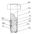
図8は、A第1締結部材の立面図でありA1頭部から先端方向へ円柱形のボルト軸が延出されていて、その先端より頭部方向に徐々に縮径された円錐形状に施されている。その位置は被締結体または、ねじなしナットなどの適宜な締め付け位置まで施されていて、その縮径端A3は360度斜め端に施されている。この縮径端はボルト軸外径に対し数ミリ程度小径に施されていてまた、A3 360度斜め端に施された角度は通常のねじのリード角程度で良い。 FIG. 8 is an elevational view of the A first fastening member, in which a cylindrical bolt shaft extends from the head of A1 toward the tip, and is gradually reduced in diameter from the tip toward the head. It has been subjected. The position is given to an appropriate tightening position such as a body to be fastened or a screwless nut, and the reduced diameter end A3 is given to a 360 ° oblique end. The diameter-reduced end is given a small diameter of several millimeters with respect to the outer diameter of the bolt shaft, and the angle given to the A3 360 ° oblique end may be about the lead angle of a normal screw.
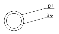
図9、図10、図11はB第2締結部材の断面図であり、図9はその上面図、図11はその下面図である。B3の360度斜め端はA3の斜め端と同角度に形成されている。A4の第1締結部分にB1の第2締結部材を巻き付け嵌合させたその外径はA2のボルト軸外径と同径状に施されてあり、そのB4の合わせ端面隙間はB3頭部から先端方向へと左右斜めに同間隔に隙間を施してある。この隙間は締結時にねじ込まれながら被締結体内側面に圧接される。また、B第2締結部分のB2折り曲げ部分を外側方向に曲げることにより、被締結体貫通孔内側面に弾性を生じさせながら押し圧接させることができ空回転を防ぎ締結させることができる。 9, FIG. 10 and FIG. 11 are sectional views of the B second fastening member, FIG. 9 is a top view thereof, and FIG. 11 is a bottom view thereof. The 360-degree oblique end of B3 is formed at the same angle as the oblique end of A3. The outer diameter of the second fastening member of B1 wound around and fitted to the first fastening portion of A4 is made the same diameter as the outer diameter of the bolt shaft of A2, and the gap between the end faces of B4 is from the head of B3. A gap is provided at the same interval diagonally left and right in the distal direction. This gap is pressed against the side of the body to be fastened while being screwed in at the time of fastening. Further, by bending the B2 bent portion of the B second fastening portion in the outward direction, the inner surface of the fastened body through-hole can be pressed and pressed while generating elasticity, and can be fastened and fastened.
図12は、A4第1締結部分にB1の第2締結部材上下厚みの違う平鉄板を巻きつける平面図である。図13のB1の平鉄板は上下厚みの違う薄平鉄板をA4締結部分に巻きつけるのであるが、このB1の平鉄板はできる限り薄平鉄板が好ましくA6のテーパ部分がA2のボルト軸に対し傾斜角度が少なければより好ましく少しの摩擦抵抗により強力な圧接力を得ることができるからである。できる限り薄平鉄板が好ましくまた、鍛造などの製造も容易にでき安価に提供ができる。 FIG. 12 is a plan view of winding a flat iron plate having a different thickness on the second fastening member B1 on the A4 first fastening portion. The flat iron plate of B1 in FIG. 13 is obtained by winding a thin flat iron plate having a different vertical thickness around the A4 fastening portion. The flat iron plate of B1 is preferably a thin flat iron plate as much as possible, and the taper portion of A6 is relative to the bolt shaft of A2. This is because if the angle of inclination is small, a strong pressure contact force can be obtained with a small amount of frictional resistance. A thin flat iron plate is preferable as much as possible, and manufacturing such as forging can be easily performed and provided at low cost.
図14、図15、図16は、B2第2締結部材であり図15はその立面図である。B2締結部材B4の合わせ端面隙間は、そのB3頭部より先端方向に左右斜めに同間隔に隙間が施されている。また、その頭部B3は360度斜めに形成されその角度はねじのリード角程度が好ましく、図14はその上面図であり、図16はその下面図である。また、前述してきた第1締結部材、第2締結部材は金属による材質で説明してきたが、樹脂又は強化プラスチックなどの材質によっても製造が可能である。 14, FIG. 15 and FIG. 16 are B2 second fastening members, and FIG. 15 is an elevation view thereof. The gap between the end faces of the B2 fastening member B4 is provided at the same interval obliquely from side to side in the tip direction from the B3 head. Further, the head B3 is formed at an angle of 360 degrees, and the angle is preferably about the lead angle of the screw. FIG. 14 is a top view thereof, and FIG. 16 is a bottom view thereof. Further, although the first fastening member and the second fastening member described above have been described using materials made of metal, they can also be manufactured using materials such as resin or reinforced plastic.
以上、本発明実施例に基づき具体的に説明してきたが、本発明は上記に限定される物ではなく、その要旨を逸脱しない範囲で種々変形可能であることは言うまでもない。前述した各実施例において、第1締結部材ボルトのヘッド部を六角に形成した例を示したが、六角孔つきボルトやフランジボルトの形状に変更してもよくまた、小形の場合はナベ頭小ねじ、トラスト頭小ねじの形状に変更しても良い。 Although the present invention has been specifically described above based on the embodiments of the present invention, it is needless to say that the present invention is not limited to the above and can be variously modified without departing from the gist thereof. In each of the above-described embodiments, the example in which the head portion of the first fastening member bolt is formed in a hexagon is shown. However, the shape may be changed to a hexagon socket head bolt or a flange bolt. You may change into the shape of a screw and a trust head machine screw.
本発明は、機械器具、電気器具、車両、建設、建築、鉄道、航空機等に用いる被締結体の締結に摘要可能である。 INDUSTRIAL APPLICABILITY The present invention can be used for fastening a body to be fastened used in a machine tool, an electric tool, a vehicle, a construction, a building, a railway, an aircraft, and the like.
A 第1締結部材
A1 頭部
A2 ボルト軸
A3 360度斜め切り込み端
A4 第1締結部分
A5 第1締結部材先端
B 第2締結部材外周面
B1 第2締結部材
B2 折り曲げ部分
B3 360度斜め切り込み端
B4 合わせ端面隙間
C1 隙間
C2 被締結体隙間
D1 被締結体
D2 被締結体
E ねじなしナットA 1st fastening member A1 Head A2 Bolt axis A3 360 degree diagonal cut end A4 1st fastening part A5 1st fastening member tip B 2nd fastening member outer peripheral surface B1 2nd fastening member B2 Bending part B3 360 degree oblique cutting end B4 Alignment end face clearance C1 Clearance C2 Fastened body gap D1 Fastened body D2 Fastened body E Screwless nut
Claims (6)
Priority Applications (1)
| Application Number | Priority Date | Filing Date | Title |
|---|---|---|---|
| JP2016130979A JP2017223346A (en) | 2016-06-14 | 2016-06-14 | Anti-loosening fastening member |
Applications Claiming Priority (1)
| Application Number | Priority Date | Filing Date | Title |
|---|---|---|---|
| JP2016130979A JP2017223346A (en) | 2016-06-14 | 2016-06-14 | Anti-loosening fastening member |
Publications (1)
| Publication Number | Publication Date |
|---|---|
| JP2017223346A true JP2017223346A (en) | 2017-12-21 |
Family
ID=60688104
Family Applications (1)
| Application Number | Title | Priority Date | Filing Date |
|---|---|---|---|
| JP2016130979A Pending JP2017223346A (en) | 2016-06-14 | 2016-06-14 | Anti-loosening fastening member |
Country Status (1)
| Country | Link |
|---|---|
| JP (1) | JP2017223346A (en) |
-
2016
- 2016-06-14 JP JP2016130979A patent/JP2017223346A/en active Pending
Similar Documents
| Publication | Publication Date | Title |
|---|---|---|
| US6758646B1 (en) | Structure for preventing loosening of threaded fasteners | |
| JP5360848B1 (en) | Nut locking device | |
| JP4519045B2 (en) | Screw locking structure | |
| US8702363B2 (en) | Lock nut and a fastening unit comprising the same | |
| JP2014105797A (en) | Reverse rotation preventive structure of screw body | |
| JP2013087947A (en) | Crossbolt locking combination nut | |
| JP2008038947A (en) | Locking mechanism for screw | |
| JP2016145607A (en) | Retention nut | |
| WO1998009086A1 (en) | Lock nut | |
| JP2019039555A (en) | Looseness prevention fastening structure | |
| KR20180043692A (en) | Non-release bolt and nut | |
| WO2018116724A1 (en) | Male threaded member | |
| JP7016204B2 (en) | Loosening prevention fastening structure | |
| JP4508943B2 (en) | Double nut | |
| JP2010133446A (en) | Screw and fastening structure using the screw | |
| JP3155204U (en) | Eccentric lock nut | |
| JP2017223346A (en) | Anti-loosening fastening member | |
| WO2004113744A1 (en) | Loosening prevention structure for bolt and nut | |
| JPH09210039A (en) | Detent nut | |
| JP5089327B2 (en) | Fastening member | |
| JP4618567B2 (en) | Locking nut | |
| JP2014105862A (en) | Reverse rotation preventive structure of screw body | |
| JP3182047U (en) | Bolt and nut locking structure | |
| JP2014219093A (en) | Fastening member | |
| CN108343665B (en) | Locknut, screw fastening external member and screw fastening assembly |