JP2017219139A5 - - Google Patents
Download PDFInfo
- Publication number
- JP2017219139A5 JP2017219139A5 JP2016114768A JP2016114768A JP2017219139A5 JP 2017219139 A5 JP2017219139 A5 JP 2017219139A5 JP 2016114768 A JP2016114768 A JP 2016114768A JP 2016114768 A JP2016114768 A JP 2016114768A JP 2017219139 A5 JP2017219139 A5 JP 2017219139A5
- Authority
- JP
- Japan
- Prior art keywords
- inertia
- coil spring
- holder
- rotational speed
- coupling coil
- Prior art date
- Legal status (The legal status is an assumption and is not a legal conclusion. Google has not performed a legal analysis and makes no representation as to the accuracy of the status listed.)
- Granted
Links
- 230000001808 coupling Effects 0.000 description 86
- 238000010168 coupling process Methods 0.000 description 86
- 238000005859 coupling reaction Methods 0.000 description 86
- 230000002093 peripheral Effects 0.000 description 64
- 239000006096 absorbing agent Substances 0.000 description 19
- 238000007906 compression Methods 0.000 description 10
- 230000005540 biological transmission Effects 0.000 description 8
- 239000010720 hydraulic oil Substances 0.000 description 5
- 230000036961 partial Effects 0.000 description 5
- 230000002238 attenuated Effects 0.000 description 3
- 230000001264 neutralization Effects 0.000 description 3
- 230000002829 reduced Effects 0.000 description 3
- 239000000969 carrier Substances 0.000 description 2
- 230000000875 corresponding Effects 0.000 description 1
- 238000010586 diagram Methods 0.000 description 1
- 230000000694 effects Effects 0.000 description 1
- 239000012530 fluid Substances 0.000 description 1
- 230000004048 modification Effects 0.000 description 1
- 238000006011 modification reaction Methods 0.000 description 1
- 230000001629 suppression Effects 0.000 description 1
- 238000003466 welding Methods 0.000 description 1
Images


Description
本発明は、動吸振装置、特に、捩り振動を吸収するための動吸振装置に関する。 The present invention relates to a dynamic vibration absorber, and more particularly to a dynamic vibration absorber for absorbing torsional vibration.
従来の動吸振装置、例えばダイナミックダンパは、回転部(ダンパプレート52)と、慣性部(1対のイナーシャリング53、1対の蓋部材54)と、弾性部(コイルスプリング55)とを、有している(特許文献1を参照)。このダイナミックダンパでは、捩り振動が回転部に伝達されると、慣性部が、弾性部を介して、周方向に移動する。この慣性部の移動によって、捩り振動が吸収される。
A conventional dynamic vibration absorber, for example, a dynamic damper has a rotating part ( damper plate 52 ), an inertia part (a pair of
従来の動吸振装置では、回転部に伝達された捩り振動を吸収するために、慣性部を周方向に移動させている。この動吸振装置では、慣性部と回転中心との距離が一定の状態で、慣性部は周方向に移動する。 In the conventional dynamic vibration absorber, the inertia part is moved in the circumferential direction to absorb the torsional vibration transmitted to the rotating part. In this dynamic vibration absorber, the inertia part moves in the circumferential direction with a constant distance between the inertia part and the rotation center.
ここで、慣性部の質量及び弾性部の剛性が一定であると考えると、慣性部は、所定の回転速度すなわち共振回転速度で、効果的に作動する。すなわち、従来の動吸振装置は、慣性部の質量(一定)及び弾性部の剛性(一定)に対応した1つの共振回転速度おいて、捩り振動を効果的に吸収する。このため、従来の動吸振装置では、回転部の回転速度が共振回転速度から外れた場合、捩り振動を吸収する効果が低減するという問題がある。 Here, assuming that the mass of the inertia part and the rigidity of the elastic part are constant, the inertia part effectively operates at a predetermined rotation speed, that is, a resonance rotation speed. That is, the conventional dynamic vibration absorber effectively absorbs torsional vibration at one resonance rotational speed corresponding to the mass (constant) of the inertia part and the rigidity (constant) of the elastic part. For this reason, the conventional dynamic vibration absorber has a problem that the effect of absorbing torsional vibration is reduced when the rotational speed of the rotating part deviates from the resonance rotational speed.
本発明は、上記の問題に鑑みてなされたものであって、本発明の目的は、捩り振動を好適に吸収可能な動吸振装置を、提供することにある。 The present invention has been made in view of the above problems, and an object of the present invention is to provide a dynamic vibration absorber capable of suitably absorbing torsional vibration.
(1)本発明の一側面に係る動吸振装置は、捩り振動を吸収するためのものである。本動吸振装置は、回転部と、慣性部と、弾性部とを、備える。回転部には、上記の捩り振動が伝達される。回転部は、回転中心まわりに回転可能に構成される。慣性部は、遠心力によって回転部に対して径方向に移動可能、且つ上記の捩り振動によって回転部に対して周方向に移動可能に、回転部に設けられる。弾性部は、回転部及び慣性部を連結する。 (1) A dynamic vibration absorber according to one aspect of the present invention is for absorbing torsional vibration. The dynamic vibration absorber includes a rotating part, an inertia part, and an elastic part. The torsional vibration is transmitted to the rotating portion. The rotating unit is configured to be rotatable around the rotation center. The inertia part is provided in the rotating part so as to be movable in the radial direction with respect to the rotating part by centrifugal force and to be movable in the circumferential direction with respect to the rotating part by the torsional vibration. The elastic part connects the rotating part and the inertia part.
本動吸振装置では、弾性部が慣性部及び回転部を連結した状態において、慣性部に遠心力が作用すると、この遠心力によって慣性部が回転部に対して径方向に移動する。そして、慣性部は、移動後の径方向位置において、上記の捩り振動によって回転部に対して周方向に移動する。この慣性部の移動によって、上記の捩り振動が吸収される。 In this dynamic vibration absorber, when a centrifugal force acts on the inertia part in a state where the elastic part connects the inertia part and the rotation part, the inertia part moves in the radial direction with respect to the rotation part by the centrifugal force. The inertia part moves in the circumferential direction with respect to the rotation part by the torsional vibration at the radial position after the movement. The torsional vibration is absorbed by the movement of the inertia part.
本動吸振装置では、遠心力例えば回転速度が変化すると、慣性部と回転中心との距離が変化する。これにより、慣性部の有効質量(見かけの質量)が、変化する。そして、この有効質量の変化に応じて、共振回転速度が変化する。このように、本動吸振装置では、遠心力の変化例えば回転速度の変化に応じて、共振回転速度を変化させることができる。すなわち、遠心力(回転速度)の変化に応じて、捩り振動を好適に吸収することができる。 In this dynamic vibration absorber, when the centrifugal force, for example, the rotational speed changes, the distance between the inertia part and the rotation center changes. Thereby, the effective mass (apparent mass) of an inertia part changes. And according to the change of this effective mass, the resonance rotational speed changes. Thus, in this dynamic vibration absorber, the resonance rotational speed can be changed in accordance with a change in centrifugal force, for example, a change in rotational speed. That is, torsional vibrations can be suitably absorbed according to changes in centrifugal force (rotational speed).
(2)本発明の別の側面に係る動吸振装置では、慣性部が、径方向及び周方向に移動可能に、回転部に係合することが、好ましい。この構成によって、特別な構成を用意することなく、慣性部を径方向及び周方向に移動させることができる。 (2) In the dynamic vibration damping device according to another aspect of the present invention, it is preferable that the inertia portion engages with the rotating portion so as to be movable in the radial direction and the circumferential direction. With this configuration, the inertial portion can be moved in the radial direction and the circumferential direction without preparing a special configuration.
(3)本発明の別の側面に係る動吸振装置では、回転部が配置部を有することが、好ましい。配置部は、慣性部を径方向及び周方向に移動可能に配置するためのものである。この構成によって、特別な構成を用意することなく、慣性部を径方向及び周方向に移動させることができる。 (3) In the dynamic vibration damping device according to another aspect of the present invention, it is preferable that the rotating portion has an arrangement portion. An arrangement | positioning part is for arrange | positioning an inertia part so that a movement to radial direction and a circumferential direction is possible. With this configuration, the inertial portion can be moved in the radial direction and the circumferential direction without preparing a special configuration.
(4)本発明の別の側面に係る動吸振装置では、配置部が、第1被当接部と、第2被当接部とを有することが、好ましい。第1被当接部には、慣性部の径方向内側部が当接する。第2被当接部には、慣性部の径方向外側部が当接する。 (4) In the dynamic vibration damping device according to another aspect of the present invention, it is preferable that the arrangement portion includes a first contacted portion and a second contacted portion. The radially inner part of the inertia part comes into contact with the first contacted part. The radially outer portion of the inertia portion abuts on the second abutted portion.
この場合、例えば、遠心力が第1所定値より小さい場合、例えば遠心力が作用していない場合や遠心力が小さい場合(遠心力が慣性部の質量より小さい場合)、慣性部の径方向内側部が、第1被当接部に当接する。ここで、慣性部及び第1被当接部の摩擦力が、慣性部に作用する周方向力より大きい場合は、慣性部は周方向に移動不能である。 In this case, for example, when the centrifugal force is smaller than the first predetermined value, for example, when the centrifugal force is not acting or when the centrifugal force is small (when the centrifugal force is smaller than the mass of the inertial portion), the radially inner side of the inertial portion The portion comes into contact with the first contacted portion. Here, when the frictional force of the inertia part and the first contacted part is larger than the circumferential force acting on the inertia part, the inertia part is immovable in the circumferential direction.
そして、遠心力が徐々に大きくなり第2所定値に到達すると、慣性部の径方向外側部が、第2被当接部に当接する。ここで、慣性部及び第2被当接部の摩擦力が、慣性部に作用する周方向力より大きい場合は、慣性部は周方向に移動不能である。 When the centrifugal force gradually increases and reaches the second predetermined value, the radially outer portion of the inertia portion comes into contact with the second contacted portion. Here, when the frictional force of the inertia part and the second contacted part is larger than the circumferential force acting on the inertia part, the inertia part is immovable in the circumferential direction.
これにより、遠心力が第1所定値以上且つ第2所定値未満の範囲、例えば回転速度が所定の範囲において、慣性部を捩り振動によって周方向に移動させることができる。このように、本動吸振装置では、設計者が所望する回転速度の範囲で、捩り振動を好適に吸収することができる。 Thus, the inertial portion can be moved in the circumferential direction by torsional vibration in a range where the centrifugal force is not less than the first predetermined value and less than the second predetermined value, for example, the rotational speed is in the predetermined range. Thus, the dynamic vibration absorber can suitably absorb torsional vibrations within the range of the rotational speed desired by the designer.
(5)本発明の別の側面に係る動吸振装置は、位置決め構造をさらに備えることが、好ましい。位置決め構造は、慣性部を回転部に対して周方向に位置決めする。位置決め構造は、第1位置決め部と、第2位置決め部とを、有する。第1位置決め部は、第1被当接部に設けられる。第2位置決め部は、径方向内側部に設けられ、第1位置決め部に係合する。この構成によって、慣性部を回転部に対して安定的に位置決めすることができる。 (5) It is preferable that the dynamic vibration damping device according to another aspect of the present invention further includes a positioning structure. The positioning structure positions the inertial portion in the circumferential direction with respect to the rotating portion. The positioning structure has a first positioning portion and a second positioning portion. The first positioning part is provided on the first contacted part. The second positioning portion is provided on the radially inner portion and engages with the first positioning portion. With this configuration, the inertial portion can be stably positioned with respect to the rotating portion.
(6)本発明の別の側面に係る動吸振装置では、弾性部が、径方向における慣性部の移動によって変形可能であり、且つ周方向における慣性部の移動によって変形可能であることが、好ましい。 (6) In the dynamic vibration damping device according to another aspect of the present invention, the elastic portion is preferably deformable by movement of the inertia portion in the radial direction and deformable by movement of the inertia portion in the circumferential direction. .
この場合、遠心力によって慣性部が径方向に移動すると、弾性部が径方向に変形する。この弾性部の形状変化によって、径方向と交差する方向における弾性部の剛性(以下、剪断剛性と記す)も、変化する。これにより、動吸振装置の共振回転速度が変化する。この状態で、慣性部が弾性部を介して回転部に対して周方向に移動すると、捩り振動が吸収される。 In this case, when the inertia part moves in the radial direction by centrifugal force, the elastic part is deformed in the radial direction. Due to the shape change of the elastic part, the rigidity of the elastic part in the direction intersecting the radial direction (hereinafter referred to as shear rigidity) also changes. Thereby, the resonance rotational speed of the dynamic vibration absorber changes. In this state, when the inertia part moves in the circumferential direction with respect to the rotating part via the elastic part, torsional vibration is absorbed.
このように、本動吸振装置では、遠心力の変化例えば回転速度の変化に応じて、共振回転速度を変化させることができる。すなわち、遠心力(回転速度)の変化に応じて、捩り振動を好適に吸収することができる。 Thus, in this dynamic vibration absorber, the resonance rotational speed can be changed in accordance with a change in centrifugal force, for example, a change in rotational speed. That is, torsional vibrations can be suitably absorbed according to changes in centrifugal force (rotational speed).
(7)本発明の別の側面に係る動吸振装置では、弾性部がコイルスプリングであることが好ましい。この場合、コイルスプリングの一端部は回転部に支持され、コイルスプリングの他端部は慣性部に支持される。 (7) In the dynamic vibration damping device according to another aspect of the present invention, the elastic portion is preferably a coil spring. In this case, one end portion of the coil spring is supported by the rotating portion, and the other end portion of the coil spring is supported by the inertia portion.
この構成では、遠心力によって慣性部が径方向に移動すると、コイルスプリングが軸方向に圧縮変形し、コイルスプリングの剪断剛性が変化する。この状態で、慣性部がコイルスプリングを介して回転部に対して周方向に移動すると、捩り振動が吸収される。 In this configuration, when the inertia part moves in the radial direction by the centrifugal force, the coil spring is compressed and deformed in the axial direction, and the shear rigidity of the coil spring changes. In this state, when the inertia part moves in the circumferential direction with respect to the rotating part via the coil spring, the torsional vibration is absorbed.
このように、本動吸振装置では、遠心力の変化例えば回転速度の変化に応じて、共振回転速度を変化させることができる。すなわち、遠心力(回転速度)の変化に応じて、捩り振動をより好適に吸収することができる。 Thus, in this dynamic vibration absorber, the resonance rotational speed can be changed in accordance with a change in centrifugal force, for example, a change in rotational speed. That is, torsional vibration can be more suitably absorbed in accordance with changes in centrifugal force (rotational speed).
(8)本発明の別の側面に係る動吸振装置では、弾性部が、不等間隔のコイルスプリングであることが好ましい。 (8) In the dynamic vibration damping device according to another aspect of the present invention, the elastic part is preferably a coil spring with unequal intervals.
この場合、コイルスプリングの線間の少なくとも一部が、不等間隔に設定される。これにより、遠心力の変化例えば回転速度の変化に応じて、共振回転速度を好適に変化させることができる。 In this case, at least a part between the coil spring lines is set at unequal intervals. Thereby, the resonance rotational speed can be suitably changed according to the change of the centrifugal force, for example, the change of the rotational speed.
本発明では、動吸振装置において、捩り振動を好適に吸収することができる。 In the present invention, torsional vibration can be suitably absorbed in the dynamic vibration absorber.
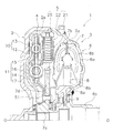
図1は、本発明の一実施形態によるダイナミックダンパ装置5を有するトルクコンバータ1の断面部分図である。図1の左側にはエンジン(図示せず)が配置され、図の右側にトランスミッション(図示せず)が配置されている。なお、図1に示すO−Oがトルクコンバータ1の回転中心である。また、以下では、回転中心Oから離れる方向を径方向と記し、回転中心Oに沿う方向を軸方向と記し、回転中心Oまわりの方向を周方向と記すことがある。
FIG. 1 is a partial sectional view of a
[トルクコンバータの全体構成]
トルクコンバータ1は、エンジン側のクランクシャフト(図示せず)からトランスミッションの入力シャフトにトルクを伝達するための装置である。図1に示すように、トルクコンバータ1は、フロントカバー2と、トルクコンバータ本体3と、ロックアップ装置4と、ダイナミックダンパ装置5(動吸振装置の一例)とから、構成されている。
[Overall configuration of torque converter]
The
フロントカバー2は、入力側の部材に固定される。フロントカバー2は、実質的に円板状の部材であり、その外周部にはトランスミッション側に突出する外周筒状部2aが形成されている。
The
トルクコンバータ本体3は、3種の羽根車、例えばインペラ6、タービン7、及びステータ8から、構成される。
The
インペラ6は、フロントカバー2の外周筒状部2aに溶接により固定されたインペラシェル6aと、その内側に固定された複数のインペラブレード6bと、インペラシェル6aの内周側に設けられた筒状のインペラハブ6cとから、構成されている。
The impeller 6 includes an impeller shell 6a fixed to the outer peripheral
タービン7は、流体室内において、インペラ6に軸方向に対向して配置されている。タービン7は、タービンシェル7aと、タービンシェル7aに固定された複数のタービンブレード7bと、タービンシェル7aの内周側に固定されたタービンハブ7cとから、構成されている。タービンハブ7cは、径方向外側に延びるフランジ7dを、有している。フランジ7dには、タービンシェル7aの内周部が、固定手段例えば複数のリベット51によって、固定されている。また、タービンハブ7cの内周部には、トランスミッションの入力シャフト(図示せず)が、スプライン係合している。
The turbine 7 is disposed in the fluid chamber so as to face the impeller 6 in the axial direction. The turbine 7 includes a
ステータ8は、タービン7からインペラ6へと戻る作動油を整流する。ステータ8は、インペラ6及びタービン7の内周部において、インペラ6及びタービン7の軸方向間に配置される。ステータ8は、主に、ステータキャリア8aと、その外周面に設けられた複数のステータブレード8bとから、構成されている。ステータキャリア8aは、ワンウエイクラッチ9を介して、固定シャフトに支持されている。
The
[ロックアップ装置]
図1に示すように、ロックアップ装置4は、フロントカバー2とタービン7との間の空間において、フロントカバー2とタービン7との軸方向間に配置されている。ロックアップ装置4は、クラッチ部10と、ダンパ部11とを、有している。
[Lock-up device]
As shown in FIG. 1, the
<クラッチ部>
図1及び図2に示すように、クラッチ部10は、ピストン12と、摩擦フェーシング13とを、有している。
<Clutch part>
As shown in FIGS. 1 and 2, the
ピストン12は、実質的に環状に形成されている。ピストン12は、フロントカバー2とダンパ部11との軸方向間に配置されている。
The
ピストン12は、ダンパ部11に対して軸方向に移動可能に、構成されている。また、ピストン12は、ダンパ部11のドライブプレート14(後述する)と一体回転可能に、構成されている。
The
ピストン12は、押圧部12aと、内周円環部12bと、外周円環部12cとを、有している。押圧部12aは、摩擦フェーシング13をフロントカバー2に押し付けるために、設けられている。押圧部12aは、ピストン12の外周側に設けられている。詳細には、押圧部12aは、軸方向においてフロントカバーに対向するように、ピストン12の外周側に設けられている。
The
内周円環部12bは、ピストン12の内周側に設けられている。内周円環部12bは、実質的に円環状に形成されている。内周円環部12bは、軸方向に移動可能にタービンハブ7cの外周部に支持されている。内周円環部12b及びタービンハブ7cの間には、シール部材50が配置されている。
The inner circumferential ring portion 12 b is provided on the inner circumferential side of the
外周円環部12cは、ピストン12の外周部に設けられている。外周円環部12cは、押圧部12aの外周側において、軸方向に延びている。外周円環部12cには、複数の係合凹部12eが、形成されている。
The outer peripheral ring portion 12 c is provided on the outer peripheral portion of the
複数の係合凹部12eは、ダンパ部11に係合可能に構成されている。例えば、複数の係合凹部12eは、周方向に所定の間隔で、外周円環部12cに形成されている。複数の係合凹部12eそれぞれは、外周円環部12cにおいて軸方向に凹状に形成されている。複数の係合凹部12eには、ダンパ部11におけるドライブプレート14の複数の係合凸部14a(後述する)が、各別に係合している。例えば、各係合凹部12eは、各係合凸部14aに対して軸方向に移動可能に、各係合凸部14aに嵌合されている。
The plurality of engaging recesses 12 e are configured to be able to engage with the
摩擦フェーシング13は、ピストン12に取り付けられている。摩擦フェーシング13は、ピストン12例えば押圧部12aによって、フロントカバー2に押し付けられる。これにより、トルクが、ピストン12を介して、フロントカバー2からダンパ部11に伝達される。
The friction facing 13 is attached to the
<ダンパ部>
ダンパ部11は、フロントカバー2から入力されるトルクを伝達し、且つフロントカバー2から入力される捩り振動を減衰する。
<Damper part>
The
図1及び図2に示すように、ダンパ部11は、ドライブプレート14と、複数の外周側コイルスプリング15と、複数の内周側コイルスプリング16と、ドリブンプレート17とを、有する。
As shown in FIGS. 1 and 2, the
−ドライブプレート−
ドライブプレート14は、実質的に環状かつ円板状の部材である。図2に示すように、ドライブプレート14は、ドリブンプレート17に対して回転可能に構成されている。例えば、ドライブプレート14は、ドリブンプレート17に対して回転可能に支持されている。
−Drive plate−
The
また、ドライブプレート14は、ピストン12と一体回転可能に構成されている。例えば、ドライブプレート14は、ピストン12と一体回転可能に、ピストン12の外周円環部12cに係合している。
Further, the
具体的には、ドライブプレート14は、複数の係合凸部14aと、複数(例えば4個)の第1窓部14bと、複数(例えば4個)の第2窓部14cとを、有している。
Specifically, the
複数の係合凸部14aは、ピストン12に係合可能に構成されている。複数の係合凸部14aは、ドライブプレート14の外周部に設けられている。例えば、複数の係合凸部14aは、ドライブプレート14の外周部から径方向外側に向けて突出している。複数の係合凸部14aは、周方向に所定の間隔で、ドライブプレート14の外周部に形成されている。
The plurality of engaging protrusions 14 a are configured to be able to engage with the
各係合凸部14aは、ピストン12の各係合凹部12eの内部に、配置されている。この状態において、各係合凸部14aは、各係合凹部12eが軸方向に移動可能なように、各係合凹部12eを支持している。また、各係合凸部14aは、各係合凹部12eと一体回転可能なように、各係合凹部12eに嵌合されている。
Each engagement convex portion 14 a is disposed inside each engagement concave portion 12 e of the
複数の第1窓部14bは、ドライブプレート14の外周側に、設けられている。具体的には、複数の第1窓部14bは、周方向に所定の間隔を隔てて、ドライブプレート14に設けられている。各第1窓部14bには、複数の外周側コイルスプリング15それぞれが、配置される。
The plurality of first window portions 14 b are provided on the outer peripheral side of the
複数の第2窓部14cは、ドライブプレート14の内周側に、設けられている。具体的には、複数の第2窓部14cは、複数の第1窓部14bより径方向内周側において、周方向に所定の間隔を隔てて、ドライブプレート14に設けられている。各第2窓部14cには、複数の内周側コイルスプリング16それぞれが、配置される。
The plurality of second window portions 14 c are provided on the inner peripheral side of the
−ドリブンプレート−
図2に示すように、ドリブンプレート17は、ドライブプレート14に対して回転可能に構成されている。ドリブンプレート17は、タービンハブ7cに固定されている。
-Driven plate-
As shown in FIG. 2, the driven
ドリブンプレート17は、第1ドリブンプレート18と、第2ドリブンプレート19とを、有している。第1ドリブンプレート18及び第2ドリブンプレート19は、実質的に環状かつ円板状の部材である。第1ドリブンプレート18は、ドライブプレート14を基準として、エンジン側に配置される。第2ドリブンプレート19は、ドライブプレート14を基準として、トランスミッション側に配置される。
The driven
第1及び第2ドリブンプレート18,19は、軸方向に互いに対向して、配置される。第1及び第2ドリブンプレート18,19の軸方向間には、ドライブプレート14が配置される。第1及び第2ドリブンプレート18,19の内周部は、軸方向に互いに隣接して配置され、固定手段例えば複数のリベット51によって、タービンハブ7cに固定される。
The first and second driven plates 18 and 19 are arranged to face each other in the axial direction. A
第1ドリブンプレート18の内周部(後述する支持部18d)から径方向外側に延びる第1本体部18a、及び第2ドリブンプレート19の内周部から径方向外側に延びる第2本体部19aは、軸方向において互いに所定の間隔を隔てて、配置される。これらの部分の間には、ドライブプレート14が配置される。すなわち、ドライブプレート14は、軸方向において、第1ドリブンプレート18及び第2ドリブンプレート19の間に配置される。
A first main body portion 18a extending radially outward from an inner peripheral portion (a support portion 18d described later) of the first driven plate 18 and a second main body portion 19a extending radially outward from the inner peripheral portion of the second driven plate 19 are , And are arranged at predetermined intervals in the axial direction. A
第1ドリブンプレート18には、ドライブプレート14の内周部を支持するための支持部18dが、設けられている。具体的には、支持部18dは、第1ドリブンプレート18の第1本体部18aの内周部に、設けられる。支持部18dは、第1本体部18aの内周部からトランスミッション側に延びている。支持部18dは、実質的に環状に形成されている。支持部18dの外周面には、ドライブプレート14の内周部が配置される。このようにして、第1ドリブンプレート18は、支持部18dにおいて、ドライブプレート14を径方向に位置決めする。
The first driven plate 18 is provided with a support portion 18 d for supporting the inner peripheral portion of the
第1及び第2ドリブンプレート18,19の外周側(第1及び第2本体部18a,19aの外周側)には、複数の第3窓部18b,19bが、各別に設けられている。例えば、複数の第3窓部18b,19bは、周方向に所定の間隔を隔てて、第1及び第2本体部18a,19aの外周側に、各別に形成されている。 A plurality of third window portions 18b and 19b are separately provided on the outer peripheral sides of the first and second driven plates 18 and 19 (the outer peripheral sides of the first and second main body portions 18a and 19a). For example, the plurality of third window portions 18b and 19b are individually formed on the outer peripheral sides of the first and second main body portions 18a and 19a with a predetermined interval in the circumferential direction.
第1本体部18aの各第3窓部18b及び第2本体部19aの各第3窓部19bは、軸方向に互いに対向して配置される。また、第1本体部18aの各第3窓部18b及び第2本体部19aの各第3窓部19bの軸方向間には、ドライブプレート14の各第1窓部14bが配置される。各第1窓部14b及び各第3窓部18b,19bには、複数の外周側コイルスプリング15それぞれが、配置される。
The third window portions 18b of the first main body portion 18a and the third window portions 19b of the second main body portion 19a are arranged to face each other in the axial direction. Further, the first window portions 14b of the
第1及び第2ドリブンプレート18,19の内周側(第1及び第2本体部18a,19aの内周側)には、複数の第4窓部18c,19cが設けられている。例えば、複数の第4窓部18c,19cは、周方向に所定の間隔を隔てて、第1及び第2本体部19aの内周側に、各別に形成されている。 A plurality of fourth window portions 18c and 19c are provided on the inner peripheral side of the first and second driven plates 18 and 19 (the inner peripheral side of the first and second main body portions 18a and 19a). For example, the plurality of fourth window portions 18c and 19c are separately formed on the inner peripheral side of the first and second main body portions 19a with a predetermined interval in the circumferential direction.
第1本体部18aの各第4窓部18c及び第2本体部19aの各第4窓部19cは、軸方向に互いに対向して配置される。また、第1本体部18aの各第4窓部18c及び第2本体部19aの各第4窓部19cの軸方向間には、各第2窓部14cが配置される。各第2窓部14c及び各第4窓部18c,19cには、複数の内周側コイルスプリング16それぞれが、配置される。 The fourth window portions 18c of the first main body portion 18a and the fourth window portions 19c of the second main body portion 19a are arranged to face each other in the axial direction. In addition, the second window portions 14c are arranged between the fourth window portions 18c of the first main body portion 18a and the fourth window portions 19c of the second main body portion 19a. A plurality of inner peripheral coil springs 16 are arranged in the second window portions 14c and the fourth window portions 18c and 19c, respectively.
−外周側コイルスプリング−
複数(例えば4個)の外周側コイルスプリング15それぞれは、ドライブプレート14及びドリブンプレート17を連結する。
-Outer coil spring-
Each of the plurality of (for example, four) outer peripheral side coil springs 15 connects the
図2に示すように、複数の外周側コイルスプリング15それぞれは、ドライブプレート14の各第1窓部14bと、ドリブンプレート17(第1ドリブンプレート18及び第2ドリブンプレート19)の第3窓部18b,19bとに、配置される。
As shown in FIG. 2, each of the plurality of outer coil springs 15 includes a first window portion 14b of the
各外周側コイルスプリング15は、周方向において、各第1窓部14b及び各第3窓部18b,19bに当接している。詳細には、各外周側コイルスプリング15は、各第1窓部14b及び各第3窓部18b,19bの壁部に、当接している。また、外周側コイルスプリング15は、各第3窓部18b,19bの切り起こし部によって、軸方向への飛び出しが規制されている。
Each
−内周側コイルスプリング−
複数(例えば4個)の内周側コイルスプリング16それぞれは、ドライブプレート14及びドリブンプレート17を連結する。
-Inner circumference coil spring-
Each of the plural (for example, four) inner coil springs 16 connects the
図2に示すように、複数の内周側コイルスプリング16それぞれは、ドライブプレート14の第2窓部14cと、ドリブンプレート17(第1ドリブンプレート18及び第2ドリブンプレート19)の第4窓部18c,19cとに、配置される。
As shown in FIG. 2, each of the plurality of inner peripheral coil springs 16 includes a second window portion 14c of the
各内周側コイルスプリング16は、周方向において、各第2窓部14c及び各第4窓部18c,19cに当接している。詳細には、各内周側コイルスプリング16は、各第2窓部14c及び各第4窓部18c,19cの壁部に、当接している。また、内周側コイルスプリング16は、各第4窓部18c,19cの切り起こし部によって、軸方向への飛び出しが規制されている。
Each
[ダイナミックダンパ装置]
ダイナミックダンパ装置5は、フロントカバー2からロックアップ装置4に伝達される捩り振動を、吸収する。
[Dynamic damper device]
The
例えば、エンジンの捩り振動が、フロントカバー2からロックアップ装置4に伝達されると、この捩り振動が、ロックアップ装置4において減衰される。そして、ロックアップ装置4から出力された捩り振動が、ダイナミックダンパ装置5に伝達される。そして、ダイナミックダンパ装置5が、この捩り振動を吸収する。
For example, when the torsional vibration of the engine is transmitted from the
なお、以下では、ロックアップ装置4からダイナミックダンパ装置5に伝達される捩り振動を、入力振動と記すことがある。また、ここで用いる「捩り振動」という文言は、回転速度変動という意味を含んでいる。
Hereinafter, the torsional vibration transmitted from the
図1に示すように、ダイナミックダンパ装置5は、トルクコンバータ本体3及びロックアップ装置4の間に、配置されている。ダイナミックダンパ装置5は、ロックアップ装置4とともに、タービンハブ7cに固定されている。
As shown in FIG. 1, the
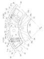
図1、図3、及び図4に示すように、ダイナミックダンパ装置5は、ホルダ20(回転部の一例)と、複数(例えば4個)のイナーシャ部21(慣性部の一例)と、複数(例えば4組)の弾性部22とを、備えている。
As shown in FIGS. 1, 3, and 4, the
−ホルダ−
ホルダ20には、ロックアップ装置4から入力振動が入力される。図1、図3、及び図4に示すように、ホルダ20は、回転中心Oまわりに回転可能に構成される。ホルダ20は、タービンハブ7cに固定されている。
-Holder-
An input vibration is input to the
図3及び図4に示すように、ホルダ20は、実質的に円板状に形成されている。ホルダ20は、外側環状部23と、内側環状部24と、ホルダ装着部25と、複数の連結部26とを、有している。
As shown in FIGS. 3 and 4, the
外側環状部23は、実質的に円環状に形成されている。詳細には、外側環状部23は、複数(例えば4個)の外側円弧部23aを、有している。各外側円弧部23aは、周方向に隣接する1対の連結部26の外周部を、周方向に連結する。
The outer
内側環状部24は、実質的に円環状に形成されている。内側環状部24は、外側環状部23より径方向内側において、外側環状部23と所定の間隔を隔てて配置されている。詳細には、内側環状部24は、複数(例えば4個)の内側円弧部24aを、有している。各内側円弧部24aは、周方向に隣接する1対の連結部26の内周部を、周方向に連結する。各内側円弧部24aは、径方向において、各外側円弧部23aに対向している。
The inner
ホルダ装着部25は、実質的に円環状に形成されている。ホルダ装着部25は、内側環状部24の内周部において、内側環状部24に一体に形成されている。ホルダ装着部25は、固定手段例えば複数のリベット52によって、タービンハブ7cに固定されている。
The
複数の連結部26は、内側環状部24及び外側環状部23を連結する部分である。具体的には、複数の連結部26は、周方向に所定の間隔を隔てて配置されている。各連結部26は、内側環状部24から外側環状部23に向けて径方向に延び、外側環状部23及び内側環状部24を連結している。各連結部26の外周部は外側環状部23に一体に形成され、各連結部26の内周部は内側環状部24に一体に形成されている。
The plurality of connecting
上記の構成を有するホルダ20には、図3に示すように、複数(例えば4個)のイナーシャ配置部27が、設けられている。各イナーシャ配置部27には、イナーシャ部21が径方向及び周方向に移動可能に配置される。具体的には、図3及び図5に示すように、各イナーシャ配置部27は、イナーシャ部21を径方向及び周方向に移動可能に配置するための窓部である。
As shown in FIG. 3, the
図5に示すように、各イナーシャ配置部27は、周方向に隣接する1対の連結部26と、外側円弧部23aと、内側円弧部24aとから、構成されている。各イナーシャ配置部27は、第1被当接部28と、第2被当接部29とを、有している。
As shown in FIG. 5, each inertia arrangement | positioning
第1被当接部28は、各イナーシャ部21の径方向内側部(後述する第1当接部33)が当接可能に構成されている。第1被当接部28は、内側環状部24の外周部例えば内側円弧部24aの外周部に、設けられている。
The first abutted
第1被当接部28は、1対の第1被当接面28aと、位置決め構造を構成する位置決め凹部28b(第1位置決め部の一例)とを、有する。1対の第1被当接面28aそれぞれは、実質的に円弧状に形成されている。1対の第1被当接面28aは、周方向において互いに間隔を隔てて設けられている。
The first abutted
位置決め凹部28bは、各イナーシャ部21を周方向に位置決めするためのものである。位置決め凹部28bは、各イナーシャ部21の位置決め凸部33b(後述する)に係合可能に構成されている。位置決め凹部28bは、周方向において1対の第1被当接面28aの間に設けられている。例えば、位置決め凹部28bは、1対の連結部26の周方向間における中央部に、設けられている。位置決め凹部28bの内面は、実質的にV字状に形成されている。位置決め凹部28bの内面は、各イナーシャ部21の位置決め凸部33bの外面に当接可能である。ここでは、位置決め凹部28bの内面には、位置決め凸部33bの先端部が部分的に当接可能になっている。
The
第2被当接部29は、各イナーシャ部21の径方向外側部(後述する第2当接部34及び第3当接部37)が、当接可能に構成されている。第2被当接部29は、外側環状部23の内周部例えば外側円弧部23aの内周部に、設けられている。第2被当接部29は、第2被当接面29aを有している。第2被当接面29aは、実質的に円弧状に形成されている。
The second abutted
−イナーシャ部−
図5から図8に示すように、複数のイナーシャ部21は、遠心力によって、ホルダ20に対して径方向に移動可能に構成されている。また、複数のイナーシャ部21は、入力振動によって、ホルダ20に対して周方向に移動可能に構成されている。
-Inertia-
As shown in FIGS. 5 to 8, the plurality of
各イナーシャ部21は、ホルダ20に設けられる。各イナーシャ部21は、径方向及び周方向に移動可能に、ホルダ20に係合している。各イナーシャ部21は、径方向においてホルダ20に当接可能であり、ホルダ20によって径方向の移動が規制される。
Each
例えば、各イナーシャ部21は、ホルダ20のイナーシャ配置部27に、配置される。各イナーシャ部21及びイナーシャ配置部27の間には、隙間が形成されている。各イナーシャ部21は、ホルダ20において周方向に隣接する1対の連結部26に、係合している。各イナーシャ部21は、径方向において、ホルダ20のイナーシャ配置部27に当接可能である。
For example, each
詳細には、図3に示すように、各イナーシャ部21は、第1質量部30と、複数(例えば2組)の第2質量部31とを、有している。
Specifically, as shown in FIG. 3, each
・第1質量部
図5から図8に示すように、第1質量部30は、実質的に円弧板状に形成されている。第1質量部30は、イナーシャ配置部27の内部に配置される。第1質量部30とイナーシャ配置部27との間には、上記の隙間が形成されている。
-1st mass part As shown in FIGS. 5-8, the 1st
第1質量部30は、1対の収納凹部32と、第1当接部33と、第2当接部34とを、有している。1対の収納凹部32は、各弾性部22を収納するために設けられている。各収納凹部32は、第1質量部30において軸方向に貫通し且つ径方向外方に開口している。
The first
1対の収納凹部32には、各弾性部22例えば2個の連結用コイルスプリング40(後述する)が、各別に配置される。各収納凹部32の底部は、各連結用コイルスプリング40の一端部を支持可能に構成されている。例えば、各収納凹部32の底部の周方向幅は、弾性部22の一端部の周方向幅例えば各連結用コイルスプリング40の一端部の外径と、実質的に同じである。
In the pair of storage recesses 32, each
各収納凹部32の開口部は、各連結用コイルスプリング40が、スプリング軸方向と交差する交差方向に変形可能に、構成されている。例えば、各収納凹部32の開口部の周方向幅は、各収納凹部32の底部の周方幅より大きい。この構成によって、各連結用コイルスプリング40の一端部が各収納凹部32の底部に支持された状態で、各連結用コイルスプリング40の他端部が、各連結用コイルスプリング40の一端部に対して、上記の交差方向例えば周方向に、移動可能になる。すなわち、各連結用コイルスプリング40は、各収納凹部32の内部において、上記の交差方向例えば周方向に変形可能になる。
The opening of each
第1当接部33は、第1質量部30の内周部に設けられている。第1当接部33は、イナーシャ配置部27の第1被当接部28に当接可能である。第1当接部33によって、上記のイナーシャ部21の径方向内側部が構成される。
The
第1当接部33は、1対の第1当接面33aと、位置決め構造を構成する位置決め凸部33b(第2位置決め部の一例)とを、有する。1対の第1当接面33aそれぞれは、実質的に円弧状に形成されている。1対の第1当接面33aは、周方向において互いに間隔を隔てて設けられている。1対の第1当接面33aは、イナーシャ配置部27の1対の第1被当接面28aに、当接可能である。1対の第1当接面33aが1対の第1被当接面28aに非当接である場合は、第1当接面33a及び第1被当接面28aの間には、上記の隙間が形成される。
The
位置決め凸部33bは、各イナーシャ部21を周方向に位置決めするためのものである。位置決め凸部33bは、各イナーシャ配置部27(第1被当接部28)の位置決め凹部28bに係合可能に、構成されている。具体的には、位置決め凸部33bは、周方向において1対の第1当接面33aの間に設けられている。詳細には、位置決め凸部33bは、第1質量部30における周方向中央部に、設けられている。
The positioning
位置決め凸部33bの外面は、実質的にV字状に形成されている。位置決め凸部33bの外面は、ホルダ20の位置決め凹部28bの内面に当接可能である。ここでは、位置決め凸部33bの先端部が、位置決め凹部28bの内面に部分的に当接可能になっている。
The outer surface of the positioning
第2当接部34は、第1質量部30の外周部に設けられている。第2当接部34は、イナーシャ配置部27の第2被当接部29に当接可能である。第2当接部34は、第2当接面34aを有している。第2当接面34aは、実質的に円弧状に形成されている。第2当接面34aは、ホルダ20の第2被当接面29aに当接可能である。第2当接面34aが第2被当接面29aに非当接である場合は、第2当接面34a及び第2被当接面29aの間には、上記の隙間が形成される。
The
・第2質量部
図3に示すように、複数の第2質量部31は、第1質量部30に取り付けられ、第1質量部30とともにイナーシャ体として機能する。各第2質量部31は、図5から図8に示すように、1対のカバー部35と、1対のホルダ係合部36と、第3当接部37とを、有している。
-2nd mass part As shown in FIG. 3, the several 2nd
1対のカバー部35は、各収納凹部32の軸方向両側に配置され、第1質量部30に取り付けられる。詳細には、1対のカバー部35は、各収納凹部32を軸方向両側から覆うように、第1質量部30に取り付けられる。1対のカバー部35は、固定手段例えば複数のボルト(図示しない)によって、第1質量部30に固定される。これにより、各収納凹部32に収納された各連結用コイルスプリング40の軸方向の飛び出しが、規制される。
The pair of
1対のホルダ係合部36は、各連結部26に係合する部分である。1対のホルダ係合部36は、各連結部26に対して、周方向及び径方向に移動可能に構成されている。1対のホルダ係合部36それぞれは、各カバー部35に設けられている。
The pair of
例えば、1対のホルダ係合部36それぞれは、互いに所定の間隔を隔てて配置され、各カバー部35の外周部に設けられている。1対のホルダ係合部36の間隔は、各連結部26の厚みより大きい。1対のホルダ係合部36の軸方向間には、各連結部26が配置される。
For example, each of the pair of
第3当接部37は、第2質量部31の外周部に設けられる。第3当接部37は、イナーシャ配置部27の第2被当接部29に当接可能である。第3当接部37及び第1質量部30の第2当接部34によって、上記のイナーシャ部21の径方向外側部が構成される。
The
例えば、第3当接部37は、第3当接面37aを有している。第3当接面37aは、各カバー部35の外周面及び各ホルダ係合部36の外周面から構成される。具体的には、第3当接面37aは、実質的に円弧状に形成されている。第3当接面37aの円弧形状は、第2当接面34aの円弧形状と連続するように、形成されている。これにより、第2当接面34a及び第3当接面37aは、第2被当接面29aに当接可能になる。ここで、各第2当接面34a及び各第3当接面37aが第2被当接面29aに非当接である場合は、各第2当接面34a及び各第3当接面37aと、第2被当接面29aとの間には、上記の隙間が形成される。
For example, the
−弾性部−
複数の弾性部22それぞれは、ホルダ20及びイナーシャ部21を連結する。各弾性部22は、イナーシャ部21の径方向移動によって変形可能、且つイナーシャ部21の周方向移動によって変形可能に、構成されている。
-Elastic part-
Each of the plurality of
各弾性部22は、少なくとも1つの連結用コイルスプリング40から、構成されている。ここでは、各弾性部22は、2個の連結用コイルスプリング40から、構成されている。各連結用コイルスプリング40は、遠心力によって、スプリング軸方向に伸縮可能に構成されている。また、各連結用コイルスプリング40は、入力振動によって、スプリング軸方向に交差する交差方向に変形可能に構成されている。
Each
ここで、スプリング軸方向は、例えば、スプリングが伸縮する方向である。交差方向は、例えば、回転中心Oに直交する面上においてスプリング軸方向と交差する方向である。交差方向には、周方向が含まれる。 Here, the spring axial direction is, for example, a direction in which the spring expands and contracts. The intersecting direction is, for example, a direction intersecting the spring axis direction on a plane orthogonal to the rotation center O. The intersecting direction includes the circumferential direction.
各連結用コイルスプリング40は、圧縮状態で、ホルダ20及びイナーシャ部21の径方向間に配置される。詳細には、ダイナミックダンパ装置5の中立状態、例えばイナーシャ部21に遠心力が作用していない状態で、各連結用コイルスプリング40のスプリング軸を含む直線が、回転中心Oを通過するように、各連結用コイルスプリング40は、ホルダ20及びイナーシャ部21の径方向間に配置される。
Each
例えば、各連結用コイルスプリング40の一端部は、イナーシャ部21に支持されている。各連結用コイルスプリング40の他端部は、ホルダ20に支持されている。詳細には、各連結用コイルスプリング40の一端部は、イナーシャ部21の収納凹部32の底部に、支持されている。各連結用コイルスプリング40の他端部は、ピン部材53例えばボルト部材を介して、ホルダ20に支持されている。ここでは、ピン部材53の一端部はホルダ20に固定され、ピン部材53の他端部は各連結用コイルスプリング40の内周部に配置されている。
For example, one end portion of each
このように、各連結用コイルスプリング40をホルダ20及びイナーシャ部21の間に配置することによって、イナーシャ部21がホルダ20に対して径方向に移動すると、各連結用コイルスプリング40は、スプリング軸方向に圧縮される。また、イナーシャ部21がホルダ20に対して周方向に移動すると、各連結用コイルスプリング40は、交差方向に変形する。
As described above, when each of the coupling coil springs 40 is disposed between the
ここで、各連結用コイルスプリング40は、不等間隔のコイルスプリングである。各連結用コイルスプリング40は、両端部の線間より中央部の線間の方が大きくなるように、形成されている。この構成によって、各連結用コイルスプリング40は、遠心力の大きさ例えばホルダ20に入力される回転速度の大きさに応じて、段階的に線間密着する。
Here, each
ここでは、中立状態において、各連結用コイルスプリング40の有効巻き数が8である場合を一例として説明する。図9は、各連結用コイルスプリング40が、第1回転速度から第4回転速度までの間で段階的に線間密着する場合の例である。
Here, a case where the effective number of windings of each
この場合、第1回転速度が例えば1000r/minであり、第2回転速度が例えば1300r/minである。また、第3回転速度が例えば1700r/minであり、第4回転速度が例えば2000r/minである。なお、ここで用いる回転速度の値は一例であり、他の値であってもよい。 In this case, the first rotation speed is, for example, 1000 r / min, and the second rotation speed is, for example, 1300 r / min. Further, the third rotation speed is, for example, 1700 r / min, and the fourth rotation speed is, for example, 2000 r / min. In addition, the value of the rotational speed used here is an example and may be another value.
まず、遠心力が0以上且つ第1遠心力未満である場合、例えば回転速度が0以上第1回転速度未満である場合(第1状態J1)では、各連結用コイルスプリング40は、線間密着をしていない。すなわち、各連結用コイルスプリング40の有効巻き数は、8である。この状態では、各連結用コイルスプリング40はイナーシャ部21を径方向内側に押圧し、イナーシャ部21の第1当接部33がホルダ20の第1被当接部28に当接している(図5を参照)。
First, when the centrifugal force is 0 or more and less than the first centrifugal force, for example, when the rotation speed is 0 or more and less than the first rotation speed (first state J1), each
次に、遠心力が第1遠心力以上且つ第2遠心力未満である場合、例えば回転速度が第1回転速度以上且つ第2回転速度未満である場合(第2状態J2)では、例えば、各連結用コイルスプリング40は線間密着をすることなく、伸縮する。この場合、各連結用コイルスプリング40の有効巻き数は、8である。
Next, when the centrifugal force is greater than or equal to the first centrifugal force and less than the second centrifugal force, for example, when the rotational speed is greater than or equal to the first rotational speed and less than the second rotational speed (second state J2), for example, The connecting
続いて、遠心力が所定の第2遠心力以上且つ第3遠心力未満である場合、例えば回転速度が第2回転速度以上第3回転速度未満である場合(第3状態J3)では、各連結用コイルスプリング40は、両端部を基準として1巻き目及び2巻き目が線間密着し、伸縮する。この場合、各連結用コイルスプリング40の有効巻き数は、4である。
Subsequently, when the centrifugal force is greater than or equal to a predetermined second centrifugal force and less than the third centrifugal force, for example, when the rotational speed is greater than or equal to the second rotational speed and less than the third rotational speed (third state J3), each connection The
最後に、遠心力が所定の第3遠心力以上且つ第4遠心力未満である場合、例えば回転速度が第3回転速度以上第4回転速度未満である場合(第4状態J4)では、各連結用コイルスプリング40は、両端部を基準として1巻き目から3巻き目までが線間密着し、伸縮する。この場合、各連結用コイルスプリング40の有効巻き数は、2である。
Finally, when the centrifugal force is greater than or equal to a predetermined third centrifugal force and less than the fourth centrifugal force, for example, when the rotational speed is greater than or equal to the third rotational speed and less than the fourth rotational speed (fourth state J4), each connection For the
なお、遠心力が第4遠心力に到達した場合、例えば回転速度が第4回転速度に到達した場合(第5状態J5)、イナーシャ部21の第2当接部34が、ホルダ20の第2被当接部29に当接する。これにより、イナーシャ部21の径方向外側への移動が規制され、各連結用コイルスプリング40は作動を停止する。
When the centrifugal force reaches the fourth centrifugal force, for example, when the rotational speed reaches the fourth rotational speed (fifth state J5), the
上記のように、各連結用コイルスプリング40の有効巻き数が変化した場合、各連結用コイルスプリング40の有効巻き数の変化に応じて、各連結用コイルスプリング40の交差方向の変形に寄与する剛性が、変化する。また、各連結用コイルスプリング40の圧縮量に応じても、各連結用コイルスプリング40の交差方向の変形に寄与する剛性が、変化する。
As described above, when the effective number of turns of each
なお、以下では、各連結用コイルスプリング40の交差方向の変形に寄与する剛性を、剪断剛性と記す場合がある。また、各連結用コイルスプリング40の交差方向のズレを、剪断という文言で表現している。
Hereinafter, the rigidity that contributes to the deformation in the cross direction of each
ここでは、各連結用コイルスプリング40だけの作動状態について説明しているが、ダイナミックダンパ装置5における各連結用コイルスプリング40の作動状態については、後述する[ダイナミックダンパ装置の動作]において説明する。
Here, only the operating state of each connecting
[トルクコンバータ本体及びロックアップ装置の動作]
まず、トルクコンバータ本体3の動作について説明する。フロントカバー2及びインペラ6が回転している状態では、作動油がインペラ6からタービン7へ流れ、作動油を介してインペラ6からタービン7へトルクが伝達される。タービン7に伝達されたトルクは、タービンハブ7cを介して、トランスミッションの入力シャフトに伝達される。
[Operation of torque converter body and lock-up device]
First, the operation of the
トルクコンバータ1の速度比が上昇し、入力シャフトが一定の回転速度になると、ピストン12の軸方向両側の作動油の圧力差によって、ピストン12がフロントカバー2側に移動し、ピストン12の押圧部12aによって摩擦フェーシング13がフロントカバー2に押し付けられる。これにより、クラッチ部10がオンになる。
When the speed ratio of the
以上のようなクラッチオン状態では、トルクが、ロックアップ装置4を介して、タービンハブ7cへと伝達される。具体的には、フロントカバー2に入力されたトルクが、ロックアップ装置4において「ピストン12→ドライブプレート14→複数の外周側コイルスプリング15及び複数の内周側コイルスプリング16→ドリブンプレート17」の経路で伝達され、タービンハブ7cに出力される。
In the clutch-on state as described above, torque is transmitted to the
ここで、クラッチオン状態のロックアップ装置4は、上記のようにトルクを伝達すると共に、フロントカバー2から入力される捩り振動を、減衰する。具体的には、ロックアップ装置4において捩り振動が発生すると、第1及び第3窓部14b,18b,19bに配置された複数の外周側コイルスプリング15と、第2及び第4窓部14c,18c,19cに配置された内周側コイルスプリング16とが、ドライブプレート14とドリブンプレート17との間で並列に圧縮される。このように、複数の外周側コイルスプリング15及び内周側コイルスプリング16が作動によって、捩り振動が減衰される。具体的には、複数の外周側コイルスプリング15及び内周側コイルスプリング16と、第1から第4窓部14b,14c,18b,19b,18c,19cとの摺動によって、捩り振動が減衰される。
Here, the lock-up
なお、クラッチ部10をオフにする場合は、ピストン12の軸方向両側の作動油の圧力差によって、ピストン12がタービン7側に移動する。この結果、フロントカバー2に対するピストン12の押圧部12aの押圧が、解除される。これにより、クラッチ部10が、オフになる。
When the
[ダイナミックダンパ装置の動作]
<ダイナミックダンパ装置の動作概要>
上記の[トルクコンバータ本体及びロックアップ装置の動作]で説明した経路において、ロックアップ装置4に伝達されたトルクは、タービンハブ7cを介して、トランスミッション側の部材に伝達される。このとき、タービンハブ7cには、ロックアップ装置4とともに、ダイナミックダンパ装置5が設けられているので、ロックアップ装置4から伝達される捩り振動(入力振動)を、効果的に抑制することができる。
[Operation of dynamic damper device]
<Operation overview of dynamic damper device>
In the path described in [Operation of Torque Converter Body and Lockup Device], the torque transmitted to the
例えば、ダイナミックダンパ装置5に入力振動が伝達されると、複数のイナーシャ部21が、複数の弾性部22を介して、ホルダ20に対して径方向及び周方向に、相対移動する。例えば、遠心力によって、各イナーシャ部21がホルダ20に対して径方向に移動した状態で、入力振動によって、ホルダ20及び各イナーシャ部21は、各弾性部22の作用によって、回転方向(周方向)に位相差を生じる。この位相差の発生によって、入力振動例えば回転速度変動が、ダイナミックダンパ装置5において吸収される。
For example, when input vibration is transmitted to the
<ダイナミックダンパ装置の動作詳細>
ここでは、図9に示すように、ダイナミックダンパ装置5が、第1回転速度(例えば1000r/min)から第4回転速度(例えば2000r/min)までの間で作動する場合を、一例として説明する。また、ダイナミックダンパ装置5の共振回転速度が、第1回転速度(1000r/min)である場合を、一例として説明する。なお、ここで用いる回転速度の値は一例であり、他の値であってもよい。
<Operation details of dynamic damper device>
Here, as shown in FIG. 9, a case where the
本ダイナミックダンパ装置5では、まず、ダイナミックダンパ装置5に入力される回転速度が、0以上第1回転速度(例えば1000r/min)未満である場合(第1状態J1)、ダイナミックダンパ装置5は図5の状態である。この場合、イナーシャ部21の位置決め凸部33bがホルダ20の位置決め凹部28bに係合し、イナーシャ部21の第1当接面33aがホルダ20の第1被当接面28aに当接している。これにより、第1状態J1では、イナーシャ部21がホルダ20と一体的に回転するので、ダイナミックダンパ装置5は未作動である。
In the
次に、回転速度が第1回転速度以上且つ第2回転速度(例えば1300r/min)未満である場合(第2状態J2)は、ダイナミックダンパ装置5は図6の状態で作動する。この場合、遠心力によって、各イナーシャ部21の第1当接部33(位置決め凸部33b及び第1当接面33a)が、ホルダ20の第1被当接部28(位置決め凹部28b及び第1被当接面28a)から径方向に離反する。すると、イナーシャ部21の第2及び第3当接部34,37とホルダ20の第2被当接部29との間に隙間が設けられた状態で、各弾性部22(2個の連結用コイルスプリング40)が、ホルダ20及び各イナーシャ部21の間で、圧縮される。
Next, when the rotational speed is equal to or higher than the first rotational speed and lower than the second rotational speed (for example, 1300 r / min) (second state J2), the
ここで、各連結用コイルスプリング40が圧縮されると、各連結用コイルスプリング40の圧縮量の変化に応じて、各連結用コイルスプリング40の剪断剛性が変化する。この剪断剛性の変化によって、ダイナミックダンパ装置5の共振回転速度が変化する。例えば、図9に示すように、各連結用コイルスプリング40の圧縮量の増加に応じて、各連結用コイルスプリング40の剪断剛性、すなわちダイナミックダンパ装置5の共振回転速度が、大きくなる。
Here, when each
この第2状態J2では、各イナーシャ部21は、各弾性部22(2個の連結用コイルスプリング40)を介して、ホルダ20に対して周方向に移動する。これにより、入力振動例えば回転速度変動が、ダイナミックダンパ装置5において吸収される。
In the second state J2, each
この場合、各イナーシャ部21の位置決め凸部33bは、ホルダ20の位置決め凹部28bの内部に配置された状態で、各イナーシャ部21はホルダ20に対して周方向に移動する。このため、各イナーシャ部21及びホルダ20の捩り角度が所定の捩り角度例えば5度に到達すると、各イナーシャ部21の位置決め凸部33bの先端部が、ホルダ20の位置決め凹部28bの壁部に当接する。
In this case, each
このように、第2状態J2では、各イナーシャ部21の位置決め凸部33b及びホルダ20の位置決め凹部28bは、ストッパとしても機能する。すなわち、第2状態J2では、中立状態を基準として、所定の捩り角度の範囲、例えば「−5度より大きく且つ+5度より小さい範囲で、各イナーシャ部21はホルダ20に対して周方向に移動する。
Thus, in the 2nd state J2, the positioning
続いて、回転速度が第2回転速度以上第3回転速度(例えば1700r/min)未満である場合(第3状態J3)は、ダイナミックダンパ装置5は図7の状態で作動する。この場合、遠心力によって、各イナーシャ部21の第1当接部33(位置決め凸部33b及び第1当接面33a)が、ホルダ20の第1被当接部28(位置決め凹部28b及び第1被当接面28a)から径方向にさらに離反する。
Subsequently, when the rotational speed is equal to or higher than the second rotational speed and lower than the third rotational speed (for example, 1700 r / min) (third state J3), the
すると、イナーシャ部21の第2及び第3当接部34,37とホルダ20の第2被当接部29との間に隙間が設けられた状態で、各弾性部22(2個の連結用コイルスプリング40)が、ホルダ20及び各イナーシャ部21の間で、さらに圧縮される。
Then, in a state where a gap is provided between the second and third abutting
すると、図9に示すように、各連結用コイルスプリング40が線間密着し、各連結用コイルスプリング40の有効巻き数は、例えば8から4に変化する。このように、各連結用コイルスプリング40の有効巻き数の変化によって、各連結用コイルスプリング40の剪断剛性が変化する。また、各連結用コイルスプリング40の圧縮量に応じても、各連結用コイルスプリング40の剪断剛性が変化する。これらの剪断剛性の変化によって、ダイナミックダンパ装置5の共振回転速度が変化する。
Then, as shown in FIG. 9, the coupling coil springs 40 are in close contact with each other, and the effective number of windings of the coupling coil springs 40 is changed from 8 to 4, for example. In this way, the shear rigidity of each
例えば、各連結用コイルスプリング40の有効巻き数が小さくなると、各連結用コイルスプリング40の剪断剛性は大きくなる。また、各連結用コイルスプリング40の圧縮量が大きくなると、各連結用コイルスプリング40の剪断剛性はさらに大きくなる。このように、各連結用コイルスプリング40の剪断剛性の増加によって、ダイナミックダンパ装置5の共振回転速度はさらに大きくなる。
For example, when the effective number of turns of each
この第3状態J3においても、各イナーシャ部21は、各弾性部22(2個の連結用コイルスプリング40)を介して、ホルダ20に対して周方向に移動する。これにより、入力振動例えば回転速度変動が、ダイナミックダンパ装置5において吸収される。
Also in the third state J3, each
続いて、回転速度が第3回転速度以上第4回転速度(例えば2000r/min)未満である場合(第4状態J4)は、ダイナミックダンパ装置5は図7の状態で作動する。なお、第4状態J4の作動状態は、連結用コイルスプリング40の有効巻き数を除いて、実質的に同じであるので、ここでは、図7を用いて説明する。
Subsequently, when the rotation speed is equal to or higher than the third rotation speed and lower than the fourth rotation speed (for example, 2000 r / min) (fourth state J4), the
この場合、遠心力によって、各イナーシャ部21の第1当接部33(位置決め凸部33b及び第1当接面33a)が、ホルダ20の第1被当接部28(位置決め凹部28b及び第1被当接面28a)から径方向にさらに離反する。
In this case, the first abutting portion 33 (positioning
すると、イナーシャ部21の第2及び第3当接部34,37とホルダ20の第2被当接部29との間に隙間が設けられた状態で、各弾性部22(2個の連結用コイルスプリング40)が、ホルダ20及び各イナーシャ部21の間で、さらに圧縮される。
Then, in a state where a gap is provided between the second and third abutting
すると、図9に示すように、各連結用コイルスプリング40が線間密着し、各連結用コイルスプリング40の有効巻き数は、例えば4から2に変化する。このように、各連結用コイルスプリング40の有効巻き数の変化によって、各連結用コイルスプリング40の剪断剛性が変化する。また、各連結用コイルスプリング40の圧縮量に応じても、各連結用コイルスプリング40の剪断剛性が変化する。これらの剪断剛性の変化によって、ダイナミックダンパ装置5の共振回転速度も変化する。
Then, as shown in FIG. 9, the coupling coil springs 40 are in close contact with each other, and the effective number of windings of each
例えば、各連結用コイルスプリング40の有効巻き数が小さくなると、各連結用コイルスプリング40の剪断剛性は大きくなる。また、各連結用コイルスプリング40の圧縮量が大きくなると、各連結用コイルスプリング40の剪断剛性はさらに大きくなる。このように、各連結用コイルスプリング40の剪断剛性の増加によって、ダイナミックダンパ装置5の共振回転速度はさらに大きくなる。
For example, when the effective number of turns of each
この第4状態J4においても、各イナーシャ部21は、各弾性部22(2個の連結用コイルスプリング40)を介して、ホルダ20に対して周方向に移動する。これにより、入力振動例えば回転速度変動が、ダイナミックダンパ装置5において吸収される。
Also in the fourth state J4, each
最後に、回転速度が第4回転速度(例えば2000r/min)に到達した場合(第5状態J5)は、ダイナミックダンパ装置5は図8の状態である。この場合、イナーシャ部21の第2及び第3当接部37が、ホルダ20の第2被当接部29に当接する。すると、イナーシャ部21は、周方向に移動不能になる。例えば、イナーシャ部21の第2及び第3当接部34,37が、ホルダ20の第2被当接部29に当接すると、イナーシャ部21及びホルダ20の間に生じる摩擦抵抗によって、イナーシャ部21は、ホルダ20に対して周方向に移動不能になる。すなわち、第5状態J5では、ダイナミックダンパ装置5が作動を停止する。
Finally, when the rotational speed reaches the fourth rotational speed (for example, 2000 r / min) (fifth state J5), the
上記のように、第2状態J2から第4状態J4では、各連結用コイルスプリング40の圧縮状態(有効巻き数及び圧縮量)に応じて、各連結用コイルスプリング40の剪断剛性が変化する。そして、図9に示すように、各連結用コイルスプリング40の剪断剛性の変化によって、ダイナミックダンパ装置5の共振回転速度が変化する。この状態で、各イナーシャ部21は、各弾性部22(2個の連結用コイルスプリング40)を介して、ホルダ20に対して周方向に移動する。
As described above, in the second state J2 to the fourth state J4, the shear rigidity of each
[まとめ]
(1)本ダイナミックダンパ装置5は、捩り振動を吸収するためのものである。本ダイナミックダンパ装置5は、ホルダ20と、イナーシャ部21と、弾性部22とを、備える。ホルダ20には、上記の捩り振動が伝達される。ホルダ20は、回転中心Oまわりに回転可能に構成される。イナーシャ部21は、遠心力によってホルダ20に対して径方向に移動可能、且つ上記の捩り振動によってホルダ20に対して周方向に移動可能に、ホルダ20に設けられる。弾性部22は、ホルダ20及びイナーシャ部21を連結する。
[Summary]
(1) The
本ダイナミックダンパ装置5では、弾性部22がイナーシャ部21及びホルダ20を連結した状態において、イナーシャ部21に遠心力が作用すると、この遠心力によってイナーシャ部21がホルダ20に対して径方向に移動する。そして、イナーシャ部21は、移動後の径方向位置において、上記の捩り振動によってホルダ20に対して周方向に移動する。このイナーシャ部21の移動によって、上記の捩り振動が吸収される。
In the
本ダイナミックダンパ装置5では、遠心力例えば回転速度が変化すると、イナーシャ部21と回転中心Oとの距離が変化する。これにより、イナーシャ部21の有効質量(見かけの質量)が、変化する。そして、この有効質量の変化に応じて、共振回転速度が変化する。このように、本ダイナミックダンパ装置5では、遠心力の変化例えば回転速度の変化に応じて、共振回転速度を変化させることができる。すなわち、遠心力(回転速度)の変化に応じて、捩り振動を好適に吸収することができる。
In the
(2)本ダイナミックダンパ装置5では、イナーシャ部21が、径方向及び周方向に移動可能に、ホルダ20に係合することが、好ましい。この構成によって、特別な構成を用意することなく、イナーシャ部21を径方向及び周方向に移動させることができる。
(2) In this
(3)本ダイナミックダンパ装置5では、ホルダ20がイナーシャ配置部27を有することが、好ましい。イナーシャ配置部27は、イナーシャ部21を径方向及び周方向に移動可能に配置するためのものである。この構成によって、特別な構成を用意することなく、イナーシャ部21を径方向及び周方向に移動させることができる。
(3) In the
(4)本ダイナミックダンパ装置5では、ホルダ20のイナーシャ配置部27が、第1被当接部28と、第2被当接部29とを有することが、好ましい。第1被当接部28には、イナーシャ部21の径方向内側部(第1当接部33)が当接する。第2被当接部29には、イナーシャ部21の径方向外側部(第2及び第3当接部34,37)が当接する。
(4) In the
この場合、例えば、第1状態J1では、イナーシャ部21の径方向内側部33が、ホルダ20の第1被当接部28に当接する。ここで、イナーシャ部21及び第1被当接部28の間の摩擦力が、イナーシャ部21に作用する周方向力より大きい場合は、イナーシャ部21は周方向に移動不能である。
In this case, for example, in the first state J <b> 1, the radially
また、第5状態J5では、イナーシャ部21の径方向外側部(第2及び第3当接部34,37)が、第2被当接部29に当接する。ここで、イナーシャ部21及び第2被当接部29の摩擦力が、イナーシャ部21に作用する周方向力より大きい場合は、イナーシャ部21は周方向に移動不能である。
Further, in the fifth state J <b> 5, the radially outer portion (second and
これにより、第1状態J1及び第5状態J5の間において、イナーシャ部21を捩り振動によって周方向に移動させることができる。このように、本ダイナミックダンパ装置5では、回転速度変動の吸収を所定の範囲、例えば第2状態J2から第4状態J4の間において、捩り振動を好適に吸収することができる。
Thereby, between the 1st state J1 and the 5th state J5, the
(5)本ダイナミックダンパ装置5は、位置決め構造をさらに備えることが、好ましい。位置決め構造は、イナーシャ部21をホルダ20に対して周方向に位置決めする。位置決め構造は、位置決め凹部28bと、位置決め凸部33bとを、有する。位置決め凹部28bは、第1被当接部28に設けられる。位置決め凸部33bは、イナーシャ部21の径方向内側部(第1当接部33)に設けられ、位置決め凹部28bに係合する。この構成によって、イナーシャ部21をホルダ20に対して安定的に位置決めすることができる。
(5) It is preferable that the
(6)本ダイナミックダンパ装置5では、弾性部22が、径方向におけるイナーシャ部21の移動によって変形可能であり、且つ周方向におけるイナーシャ部21の移動によって変形可能であることが、好ましい。
(6) In the
この場合、遠心力によってイナーシャ部21が径方向に移動すると、弾性部22が径方向に変形する。この弾性部22の形状変化によって、弾性部22の剪断剛性も、変化する。これにより、ダイナミックダンパ装置5の共振回転速度が変化する。この状態で、イナーシャ部21が弾性部22を介してホルダ20に対して周方向に移動すると、捩り振動が吸収される。
In this case, when the
このように、本ダイナミックダンパ装置5では、遠心力の変化例えば回転速度の変化に応じて、共振回転速度を変化させることができる。すなわち、遠心力(回転速度)の変化に応じて、捩り振動を好適に吸収することができる。
As described above, in the
(7)本ダイナミックダンパ装置5では、弾性部22が連結用コイルスプリング40であることが好ましい。この場合、連結用コイルスプリング40の一端部はホルダ20に支持され、連結用コイルスプリング40の他端部はイナーシャ部21に支持される。
(7) In the
この構成では、遠心力によってイナーシャ部21が径方向に移動すると、連結用コイルスプリング40が軸方向に圧縮変形し、連結用コイルスプリング40の剪断剛性が変化する。これにより、ダイナミックダンパ装置5の共振回転速度が変化する。この状態で、イナーシャ部21が、連結用コイルスプリング40を介して、ホルダ20に対して周方向に移動すると、捩り振動が吸収される。
In this configuration, when the
このように、本ダイナミックダンパ装置5では、遠心力の変化例えば回転速度の変化に応じて、共振回転速度を変化させることができる。すなわち、遠心力(回転速度)の変化に応じて、捩り振動をより好適に吸収することができる。
As described above, in the
(8)本ダイナミックダンパ装置5では、弾性部22が、不等間隔の連結用コイルスプリング40であることが好ましい。
(8) In the
この場合、各連結用コイルスプリング40の線間の少なくとも一部が、不等間隔に設定される。これにより、遠心力の変化例えば回転速度の変化に応じて、共振回転速度を好適に変化させることができる。 In this case, at least a part between the lines of the coupling coil springs 40 is set at unequal intervals. Thereby, the resonance rotational speed can be suitably changed according to the change of the centrifugal force, for example, the change of the rotational speed.
[他の実施形態]
本発明は以上のような実施形態に限定されるものではなく、本発明の範囲を逸脱することなく種々の変形又は修正が可能である。
[Other Embodiments]
The present invention is not limited to the above-described embodiments, and various changes or modifications can be made without departing from the scope of the present invention.
(a)前記実施形態では、各連結用コイルスプリング40を線間密着させる場合の例を示したが、各連結用コイルスプリング40を線間密着させることなく、各連結用コイルスプリング40の圧縮量の変化だけで、各連結用コイルスプリング40の剪断剛性を変化させてもよい。このように構成しても、ダイナミックダンパ装置5の共振回転速度を変化させ、各イナーシャ部21をホルダに対して好適に移動させることができる。
(A) In the above-described embodiment, an example in which the coupling coil springs 40 are closely contacted between the lines has been described. However, the compression amount of each
(b)前記実施形態のロックアップ装置4のクラッチ部10及びダンパ部11の構成は、前記実施形態に限定されず、どのように構成してもよい。
(B) The structure of the
(c)前記実施形態では、ダイナミックダンパ装置5が4個のイナーシャ部21を有する場合の例を示したが、イナーシャ部21の数は、前記実施形態に限定されず、複数であれば、どのように構成してもよい。
(C) In the said embodiment, although the example in case the
(d)前記実施形態では、各弾性部22が2個の連結用コイルスプリング40から構成される場合の例を示したが、連結用コイルスプリング40の数は、前記実施形態に限定されず、1個以上であれば、どのように構成してもよい。
(D) In the said embodiment, although the example in case each
5 ダイナミックダンパ装置
20 ホルダ
21 イナーシャ部
22 弾性部
27 イナーシャ配置部
28 第1被当接部
28b 位置決め凹部、位置決め構造
29 第2被当接部
33 径方向内側部、第1当接部
33b 位置決め凸部、位置決め構造
34,37 径方向外側部、第2当接部
40 連結用コイルスプリング
O 回転中心
DESCRIPTION OF
Priority Applications (3)
| Application Number | Priority Date | Filing Date | Title |
|---|---|---|---|
| JP2016114768A JP6709687B2 (en) | 2016-06-08 | 2016-06-08 | Dynamic vibration absorber |
| US15/585,606 US10436283B2 (en) | 2016-06-08 | 2017-05-03 | Dynamic vibration absorbing device |
| CN201710366022.3A CN107477161A (en) | 2016-06-08 | 2017-05-22 | Dynamic shock-absorbing means |
Applications Claiming Priority (1)
| Application Number | Priority Date | Filing Date | Title |
|---|---|---|---|
| JP2016114768A JP6709687B2 (en) | 2016-06-08 | 2016-06-08 | Dynamic vibration absorber |
Publications (3)
| Publication Number | Publication Date |
|---|---|
| JP2017219139A JP2017219139A (en) | 2017-12-14 |
| JP2017219139A5 true JP2017219139A5 (en) | 2019-03-07 |
| JP6709687B2 JP6709687B2 (en) | 2020-06-17 |
Family
ID=60573865
Family Applications (1)
| Application Number | Title | Priority Date | Filing Date |
|---|---|---|---|
| JP2016114768A Active JP6709687B2 (en) | 2016-06-08 | 2016-06-08 | Dynamic vibration absorber |
Country Status (3)
| Country | Link |
|---|---|
| US (1) | US10436283B2 (en) |
| JP (1) | JP6709687B2 (en) |
| CN (1) | CN107477161A (en) |
Families Citing this family (4)
| Publication number | Priority date | Publication date | Assignee | Title |
|---|---|---|---|---|
| CN105940242B (en) * | 2014-01-28 | 2018-02-23 | 舍弗勒技术股份两合公司 | centrifugal force pendulum |
| KR101803953B1 (en) * | 2016-05-27 | 2017-12-01 | 한국파워트레인 주식회사 | Torque convertor for vehicle |
| JP7355606B2 (en) * | 2019-10-31 | 2023-10-03 | 株式会社エクセディ | Torsion damper and damper device |
| CN114439882A (en) * | 2020-10-30 | 2022-05-06 | 广州汽车集团股份有限公司 | Dual mass flywheel and car |
Family Cites Families (4)
| Publication number | Priority date | Publication date | Assignee | Title |
|---|---|---|---|---|
| DE3645258B4 (en) * | 1985-09-07 | 2009-04-30 | Luk Lamellen Und Kupplungsbau Beteiligungs Kg | Device for damping torsional vibrations |
| US8424659B2 (en) * | 2010-01-27 | 2013-04-23 | GM Global Technology Operations LLC | Vibration absorber |
| DE102013212272B4 (en) * | 2012-07-06 | 2023-02-16 | Schaeffler Technologies AG & Co. KG | centrifugal pendulum |
| JP5878893B2 (en) | 2013-07-11 | 2016-03-08 | 株式会社エクセディ | Torque converter lockup device |
-
2016
- 2016-06-08 JP JP2016114768A patent/JP6709687B2/en active Active
-
2017
- 2017-05-03 US US15/585,606 patent/US10436283B2/en active Active
- 2017-05-22 CN CN201710366022.3A patent/CN107477161A/en active Pending
Similar Documents
| Publication | Publication Date | Title |
|---|---|---|
| JP6044725B2 (en) | Damper device and starting device | |
| JP5952432B2 (en) | Damper device and starting device | |
| JP6142812B2 (en) | Starting device | |
| KR102520918B1 (en) | Vibration reduction device | |
| JP6245871B2 (en) | Torque converter lockup device | |
| WO2015170485A1 (en) | Hydrodynamic power transmission device | |
| JP6252458B2 (en) | Damper device | |
| JP6090466B2 (en) | Damper device and starting device | |
| JP5980818B2 (en) | Torsional damper for clutch | |
| JP6709687B2 (en) | Dynamic vibration absorber | |
| JP2017219139A5 (en) | ||
| JP5999947B2 (en) | Torque converter and clutch and damper assembly | |
| JP2019039456A5 (en) | ||
| JP2017026139A (en) | Vibration attenuation device | |
| JP6524825B2 (en) | Damper device with dynamic absorber | |
| KR101376783B1 (en) | Torque convertor having twin mass damper | |
| WO2017014184A1 (en) | Vibration-damping device | |
| JP2011127686A (en) | Damper device | |
| WO2016125382A1 (en) | Dynamic vibration-absorbing device for automobile | |
| JP2014206244A (en) | Lock-up device of torque converter | |
| JP6176997B2 (en) | Torque converter lockup device | |
| JP2014206184A (en) | Lock-up device for torque converter | |
| JP6034641B2 (en) | Starting device | |
| JP6587388B2 (en) | Dynamic vibration absorber for automobile and lockup device for torque converter | |
| JP5545207B2 (en) | Centrifugal pendulum vibration absorber |