JP2017215076A - Heat exchanger - Google Patents
Heat exchanger Download PDFInfo
- Publication number
- JP2017215076A JP2017215076A JP2016108208A JP2016108208A JP2017215076A JP 2017215076 A JP2017215076 A JP 2017215076A JP 2016108208 A JP2016108208 A JP 2016108208A JP 2016108208 A JP2016108208 A JP 2016108208A JP 2017215076 A JP2017215076 A JP 2017215076A
- Authority
- JP
- Japan
- Prior art keywords
- tank
- header
- vertical wall
- leeward
- constituent member
- Prior art date
- Legal status (The legal status is an assumption and is not a legal conclusion. Google has not performed a legal analysis and makes no representation as to the accuracy of the status listed.)
- Pending
Links
Images


Abstract
Description
この発明は、たとえば自動車に搭載される冷凍サイクルであるカーエアコンに用いられる熱交換器に関する。 The present invention relates to a heat exchanger used in a car air conditioner that is a refrigeration cycle mounted on an automobile, for example.
たとえばカーエアコンのエバポレータに用いられる熱交換器として、本出願人は、先に、幅方向を通風方向に向けるとともに間隔をおいて配置された1対のヘッダタンクと、両ヘッダタンク間に配置されるとともに両端部が両ヘッダタンクに接続された複数の熱交換チューブとを備えており、両ヘッダタンクが、風下側に位置する風下側ヘッダ部と、風上側に位置する風上側ヘッダ部とを有し、両ヘッダタンクの風下側および風上側ヘッダ部間に、それぞれ複数の熱交換チューブからなる1列のチューブ列が配置されるとともに、熱交換チューブの両端部が両ヘッダタンクの風下側および風上側ヘッダ部に接続され、一方のヘッダタンクの風下側ヘッダ部の一端部に冷媒入口が設けられるとともに、同じく風上側ヘッダ部における冷媒入口と同一端部に冷媒出口が設けられ、両ヘッダタンクが、熱交換チューブが接続された第1タンク構成部材と、第1タンク構成部材に接合されかつ第1タンク構成部材における熱交換チューブとは反対側を覆う第2タンク構成部材と、第1タンク構成部材と第2タンク構成部材との間に配置された第3タンク構成部材とを有し、第3タンク構成部材に、ヘッダタンクの風下側および風上側ヘッダ部内をそれぞれ熱交換チューブの長さ方向に2つの空間に仕切る2つの仕切部が設けられ、両ヘッダタンクの通風方向両側縁部に、第1タンク構成部材の通風方向両側縁部に設けられた外側縦壁部と、第2タンク構成部材の通風方向両側縁部に設けられた内側縦壁部と、第3タンク構成部材の風下側仕切部の風下側縁部および風上側仕切部の風上側縁部に設けられ、かつ外側縦壁部と内側縦壁部との間に位置する中間縦壁部とが重なり合った積層部が設けられ、第3タンク構成部材の風下側仕切部および風上側仕切部に通風方向に延びるスリットが形成され、一端部に冷媒入口および冷媒出口を有する一方のヘッダタンクの風下側および風上側ヘッダ部の他端部、ならびに他方のヘッダタンクの風下側および風上側ヘッダ部の両端部が、それぞれ第3タンク構成部材の仕切部に形成されたスリットに挿入された被挿入板によって閉鎖され、両ヘッダタンクの風下側ヘッダ部および風上側ヘッダ部のうち少なくとも1つのヘッダ部における長手方向の両端部間において、第3タンク構成部材の仕切部に形成された少なくとも1つのスリットに被挿入板が挿入されている熱交換器を提案した(特許文献1参照)。 For example, as a heat exchanger used in an evaporator of a car air conditioner, the applicant of the present invention is arranged between a pair of header tanks and a pair of header tanks which are arranged in the width direction in the airflow direction and at intervals. And a plurality of heat exchange tubes whose both ends are connected to both header tanks, and both header tanks have a leeward header portion located on the leeward side and an leeward header portion located on the leeward side. A row of tubes each composed of a plurality of heat exchange tubes is disposed between the leeward side and the leeward header portion of both header tanks, and both ends of the heat exchange tubes are located on the leeward side of both header tanks and A refrigerant inlet is provided at one end of the leeward header portion of one header tank, and is connected to the windward header portion. A refrigerant outlet is provided at one end, and both header tanks are connected to the first tank constituent member to which the heat exchange tube is connected, and the opposite side of the first tank constituent member to the heat exchange tube in the first tank constituent member A second tank constituent member that covers the first tank constituent member and a third tank constituent member disposed between the first tank constituent member and the second tank constituent member. Two partition sections are provided to partition the inside of the windward header section into two spaces in the length direction of the heat exchange tube, on both side edges in the ventilation direction of both header tanks, on both side edges in the ventilation direction of the first tank component The outer vertical wall portion provided, the inner vertical wall portions provided at both side edges of the second tank constituent member, and the leeward side edge portion and the windward side partition portion of the leeward side partition portion of the third tank constituent member Windward edge of And a laminated portion in which an intermediate vertical wall portion located between the outer vertical wall portion and the inner vertical wall portion overlaps is provided, and ventilation is provided to the leeward side partition portion and the windward side partition portion of the third tank component member. The other end of the leeward side and the leeward header part of one header tank, and both ends of the leeward side and the leeward header part of the other header tank, each having a slit extending in the direction and having a refrigerant inlet and a refrigerant outlet at one end. Are closed by insertion plates inserted into slits formed in the partition portions of the third tank component, respectively, and the longitudinal length of at least one header portion of the leeward header portion and the leeward header portion of both header tanks Proposed a heat exchanger in which a plate to be inserted is inserted into at least one slit formed in the partition portion of the third tank constituent member between both ends in the direction (Patent Document) Reference 1).
特許文献1記載の熱交換器は、第1〜第3タンク構成部材は、それぞれ1枚のアルミニウム板にプレス加工を施すことにより形成されているので、第3タンク構成部材の中間縦壁部の外面と、両仕切部における第1タンク構成部材側を向いた面との間に丸みがつけられることは避け得ない。したがって、被挿入板と、第1タンク構成部材の外側縦壁部内面および第3タンク構成部材の丸み外面との間に隙間が生じるおそれがある。
In the heat exchanger described in
この発明の目的は、上記問題を解決し、被挿入板と、外側縦壁部内面および第3タンク構成部材の丸み外面との間に隙間が生じることを防止しうる熱交換器を提供することにある。 An object of the present invention is to provide a heat exchanger that solves the above problems and can prevent a gap from being formed between the inserted plate and the inner surface of the outer vertical wall portion and the round outer surface of the third tank constituent member. It is in.
本発明は、上記目的を達成するために以下の態様からなる。 In order to achieve the above object, the present invention comprises the following aspects.
1)幅方向を通風方向に向けるとともに長手方向を同方向に向けた状態で互いに間隔をおいて配置された1対のヘッダタンクと、両ヘッダタンク間に配置されるとともに両端部が両ヘッダタンクに接続された複数の熱交換チューブとを備えており、少なくともいずれか一方のヘッダタンクが、熱交換チューブが接続された第1タンク構成部材と、第1タンク構成部材に接合されかつ第1タンク構成部材における熱交換チューブとは反対側を覆う第2タンク構成部材と、第1タンク構成部材と第2タンク構成部材との間に配置された第3タンク構成部材とを有し、3つのタンク構成部材を有するヘッダタンクの通風方向両側縁部に、各タンク構成部材の通風方向両側縁部に形成された縦壁部が重なり合った積層部が設けられ、当該積層部が、最も外側に位置する外側縦壁部、最も内側に位置する内側縦壁部、および中間に位置する中間縦壁部からなり、第1タンク構成部材および第2タンク構成部材のうちいずれか一方に外側縦壁部が設けられるとともに、同他方に内側縦壁部が設けられ、第3タンク構成部材に中間縦壁部が設けられ、第3タンク構成部材に、ヘッダタンク内を熱交換チューブの長さ方向に2つの空間に仕切る仕切部が設けられ、第3タンク構成部材の仕切部に通風方向に延びるスリットが形成され、当該スリットに被挿入板が挿入されて第1〜第3タンク構成部材にろう材により接合されている熱交換器であって、
第3タンク構成部材の中間縦壁部の外面と、仕切部における外側縦壁部を有するタンク構成部材側を向いた面との間に丸みが存在しており、被挿入板が、外側縦壁部を有するタンク構成部材と第3タンク構成部材の仕切部との間に位置する第1部分と、内側縦壁部を有するタンク構成部材と第3タンク構成部材の仕切部との間に位置する第2部分と、スリット内に位置する第3部分とよりなり、被挿入板の第1部分における外側縦壁部側の縁部に、外側縦壁部と第3タンク構成部材の丸みとの間に嵌る嵌入部が設けられ、当該嵌入部が、外側縦壁部の内面および丸みの外面にろう材により接合されている熱交換器。
1) A pair of header tanks that are spaced apart from each other with the width direction directed to the ventilation direction and the longitudinal direction directed to the same direction, and both header tanks disposed between both header tanks A plurality of heat exchange tubes connected to each other, at least one of the header tanks being joined to the first tank constituting member to which the heat exchange tubes are connected, the first tank constituting member, and the first tank Three tanks having a second tank constituent member that covers the side of the constituent member opposite to the heat exchange tube, and a third tank constituent member disposed between the first tank constituent member and the second tank constituent member Laminated portions where the vertical wall portions formed on the both sides of the airflow direction of each tank constituent member overlap each other are provided at both side edges of the header tank having the constituent members. An outer vertical wall portion positioned on the side, an inner vertical wall portion positioned on the innermost side, and an intermediate vertical wall portion positioned in the middle, and either the first tank constituent member or the second tank constituent member is A wall portion is provided, an inner vertical wall portion is provided on the other side, an intermediate vertical wall portion is provided on the third tank constituent member, and a length direction of the heat exchange tube passes through the header tank in the third tank constituent member. And a slit extending in the ventilation direction is formed in the partition portion of the third tank constituent member, and a plate to be inserted is inserted into the slit to be connected to the first to third tank constituent members. A heat exchanger joined by a material,
A roundness exists between the outer surface of the intermediate vertical wall portion of the third tank constituent member and the surface facing the tank constituent member side having the outer vertical wall portion in the partition portion, and the inserted plate is the outer vertical wall. 1st part located between the tank structural member which has a part, and the partition part of a 3rd tank structural member, and it is located between the tank structural member which has an inner side vertical wall part, and the partition part of a 3rd tank structural member It consists of a 2nd part and the 3rd part located in a slit, and the edge part by the side of the outside vertical wall part in the 1st part of a to-be-inserted board is between an outer side vertical wall part and the roundness of a 3rd tank structural member. The heat exchanger is provided with a fitting portion that fits into the outer vertical wall portion, and the fitting portion is joined to the inner surface of the outer vertical wall portion and the round outer surface by a brazing material.
2)被挿入板の第1部分の外形が、外側縦壁部を有するタンク構成部材と第3タンク構成部材の仕切部とに囲まれた空間の横断面形状に合致し、同じく第2部分の外形が、内側縦壁部を有するタンク構成部材と第3タンク構成部材の仕切部とに囲まれた空間の横断面形状に合致し、同じく第3部分がスリットを埋めている上記1)記載の熱交換器。 2) The outer shape of the first portion of the inserted plate matches the cross-sectional shape of the space surrounded by the tank constituent member having the outer vertical wall portion and the partition portion of the third tank constituent member. The outer shape matches the cross-sectional shape of the space surrounded by the tank constituent member having the inner vertical wall portion and the partition portion of the third tank constituent member, and the third portion similarly fills the slit. Heat exchanger.
3)両ヘッダタンクが、風下側に位置する風下側ヘッダ部と、風上側に位置する風上側ヘッダ部とを備えており、熱交換チューブの両端部が両ヘッダタンクの風下側および風上側ヘッダ部に接続され、第3タンク構成部材が、ヘッダタンクの風下側および風上側ヘッダ部内をそれぞれ熱交換チューブの長さ方向に2つの空間に仕切る2つの仕切部を有し、風下側ヘッダ部の風下側縁部および風上側ヘッダ部の風上側縁部にそれぞれ前記積層部が設けられている上記1)または2)記載の熱交換器。 3) Both header tanks are provided with a leeward header portion located on the leeward side and an upwind header portion located on the leeward side, and both ends of the heat exchange tube are on the leeward side and leeward header of both header tanks. The third tank component member has two partition portions for partitioning the leeward side and the windward side header portion of the header tank into two spaces in the length direction of the heat exchange tube, respectively. The heat exchanger as described in 1) or 2) above, wherein the laminated portion is provided at each of the leeward side edge portion and the leeward side edge portion of the windward side header portion.
4)一方のヘッダタンクの風下側ヘッダ部の一端部に冷媒入口が設けられるとともに、同じく風上側ヘッダ部における冷媒入口と同一端部に冷媒出口が設けられ、一端部に冷媒入口および冷媒出口を有する前記一方のヘッダタンクの風下側および風上側ヘッダ部の他端部、ならびに他方のヘッダタンクの風下側および風上側ヘッダ部の両端部において、第3タンク構成部材の仕切部にスリットが形成され、当該スリットに挿入された被挿入板によって、前記一方のヘッダタンクの風下側および風上側ヘッダ部の他端部、ならびに他方のヘッダタンクの風下側および風上側ヘッダ部の両端部が閉鎖されている上記3)記載の熱交換器。 4) A refrigerant inlet is provided at one end of the leeward header portion of one header tank, a refrigerant outlet is provided at the same end as the refrigerant inlet in the leeward header portion, and a refrigerant inlet and a refrigerant outlet are provided at one end. A slit is formed in the partition portion of the third tank constituent member at the other end portion of the leeward side and the windward header portion of the one header tank, and at both ends of the leeward side and the windward header portion of the other header tank. The inserted plate inserted into the slit closes the other end of the leeward side and the windward header part of the one header tank, and both ends of the leeward side and the windward header part of the other header tank. The heat exchanger according to 3) above.
5)両ヘッダタンクの風下側ヘッダ部および風上側ヘッダ部のうち少なくとも1つのヘッダ部における長手方向の両端部間において、当該ヘッダ部を熱交換チューブの長さ方向に2つの空間に仕切る第3タンク構成部材の仕切部に少なくとも1つのスリットが形成され、当該スリットに被挿入板が挿入されている上記3)または4)記載の熱交換器。 5) A third part that divides the header part into two spaces in the longitudinal direction of the heat exchange tube between the longitudinal ends of at least one of the leeward header part and the leeward header part of both header tanks. The heat exchanger according to 3) or 4) above, wherein at least one slit is formed in the partition portion of the tank constituent member, and an inserted plate is inserted into the slit.
上記1)〜5)の熱交換器によれば、第3タンク構成部材の中間縦壁部の外面と、仕切部における外側縦壁部を有するタンク構成部材側を向いた面との間に丸みが存在しており、被挿入板が、外側縦壁部を有するタンク構成部材と第3タンク構成部材の仕切部との間に位置する第1部分と、内側縦壁部を有するタンク構成部材と第3タンク構成部材の仕切部との間に位置する第2部分と、スリット内に位置する第3部分とよりなり、被挿入板の第1部分における外側縦壁部側の縁部に、外側縦壁部と第3タンク構成部材の丸みとの間に嵌る嵌入部が設けられ、当該嵌入部が、外側縦壁部の内面および丸みの外面にろう材により接合されているので、被挿入板と、積層部の外側縦壁部内面および第3タンク構成部材の丸み外面との間に隙間が生じることが防止される。 According to the heat exchangers of 1) to 5) above, the outer surface of the intermediate vertical wall portion of the third tank component member is rounded between the surface facing the tank component member side having the outer vertical wall portion in the partition portion. A first component located between the tank constituent member having the outer vertical wall portion and the partition portion of the third tank constituent member, and the tank constituent member having the inner vertical wall portion, It consists of a second part located between the partition parts of the third tank component and a third part located in the slit, on the outer vertical wall part side edge of the first part of the inserted plate, Since the fitting part fitted between a vertical wall part and the roundness of a 3rd tank structural member is provided, and the said fitting part is joined to the inner surface of an outer side vertical wall part, and the outer surface of a roundness, it is a board to be inserted. There is a gap between the inner surface of the outer vertical wall portion of the laminated portion and the round outer surface of the third tank component. And is prevented.
上記4)の熱交換器においては、冷媒の外部への漏れが確実に防止される。 In the heat exchanger of 4) above, leakage of the refrigerant to the outside is surely prevented.
上記5)の熱交換器においては、ヘッダ部における被挿入板の両側の部分間での想定外の冷媒の漏れが確実に防止される。 In the heat exchanger of 5) above, unexpected refrigerant leakage between the portions on both sides of the inserted plate in the header portion is reliably prevented.
以下、この発明の実施形態を、図面を参照して説明する。以下に述べる実施形態は、この発明による熱交換器を、カーエアコンを構成する冷凍サイクルのエバポレータに適用したものである。 Embodiments of the present invention will be described below with reference to the drawings. In the embodiment described below, the heat exchanger according to the present invention is applied to an evaporator of a refrigeration cycle constituting a car air conditioner.
なお、以下の説明において、「アルミニウム」という用語には、純アルミニウムの他にアルミニウム合金を含むものとする。 In the following description, the term “aluminum” includes aluminum alloys in addition to pure aluminum.
また、以下の説明において、隣接する熱交換チューブどうしの間の通風間隙を流れる空気の下流側(図面に矢印Xで示す方向)を前、これと反対側を後というものとし、前側から後側を見た際の上下、左右、すなわち図2の上下、左右を上下、左右というものとする。 In the following description, the downstream side of the air flowing in the ventilation gap between adjacent heat exchange tubes (the direction indicated by the arrow X in the drawing) is referred to as the front side, and the opposite side is referred to as the rear side. 2 are referred to as up and down, left and right in FIG.
図1はこの発明の熱交換器を適用したエバポレータの全体構成を示し、図2〜図6はその要部の構成を示す。 FIG. 1 shows the whole structure of an evaporator to which the heat exchanger of the present invention is applied, and FIGS. 2 to 6 show the structure of the main part.
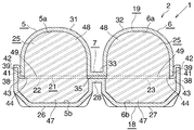
図1〜図4において、エバポレータ(1)は、幅方向を通風方向に向けるとともに長手方向を左右方向に向けた状態で、上下方向に間隔をおいて配置されたアルミニウム製上ヘッダタンク(2)およびアルミニウム製下ヘッダタンク(3)と、両ヘッダタンク(2)(3)の間に設けられた熱交換コア部(4)とを備えている。 1 to 4, the evaporator (1) is an aluminum upper header tank (2) arranged in the vertical direction with the width direction oriented in the ventilation direction and the longitudinal direction oriented in the left-right direction. And an aluminum lower header tank (3) and a heat exchange core section (4) provided between the header tanks (2) and (3).
上ヘッダタンク(2)は、風下側(前側)に位置しかつ長手方向を左右方向に向けた風下側ヘッダ部(5)と、風上側(後側)に位置しかつ長手方向を左右方向に向けた風上側ヘッダ部(6)と、両ヘッダ部(5)(6)を相互に連結一体化する連結部(7)とを備えている。下ヘッダタンク(3)は、風下側(前側)に位置しかつ長手方向を左右方向に向けた風下側ヘッダ部(8)と、風上側(後側)に位置しかつ長手方向を左右方向に向けた風上側ヘッダ部(9)と、両ヘッダ部(8)(9)を相互に連結一体化する連結部(図示略)とを備えている。以下の説明において、上ヘッダタンク(2)の風下側ヘッダ部(5)を風下側上ヘッダ部、下ヘッダタンク(3)の風下側ヘッダ部(8)を風下側下ヘッダ部、上ヘッダタンク(2)の風上側ヘッダ部(6)を風上側上ヘッダ部、下ヘッダタンク(3)の風上側ヘッダ部(9)を風上側下ヘッダ部というものとする。風下側上ヘッダ部(5)の右端部に冷媒入口(11)が設けられ、風上側上ヘッダ部(6)の右端部に冷媒出口(12)が設けられている。 The upper header tank (2) is located on the leeward side (front side) and the leeward header part (5) with the longitudinal direction facing the left and right direction, and located on the windward side (rear side) and the longitudinal direction in the left and right direction The windward header section (6) is directed and a connection section (7) that connects and integrates both header sections (5) and (6). The lower header tank (3) is located on the leeward side (front side) and the leeward side header section (8) with the longitudinal direction facing the left and right direction, and located on the windward side (rear side) and the longitudinal direction in the left and right direction A windward header section (9) directed toward the head, and a connecting section (not shown) for connecting and integrating the header sections (8) and (9) to each other. In the following description, the leeward header portion (5) of the upper header tank (2) is the leeward upper header portion, the leeward header portion (8) of the lower header tank (3) is the leeward lower header portion, and the upper header tank. The windward header section (6) of (2) is referred to as the windward upper header section, and the windward header section (9) of the lower header tank (3) is referred to as the windward lower header section. A refrigerant inlet (11) is provided at the right end of the leeward upper header portion (5), and a refrigerant outlet (12) is provided at the right end of the leeward upper header portion (6).
熱交換コア部(4)は、長手方向を上下方向に向けるとともに幅方向を通風方向に向けた状態で左右方向に間隔をおいて配置された複数のアルミニウム押出形材製扁平状熱交換チューブ(13)からなるチューブ列(14)(15)が、前後方向に並んで2列設けられ、各チューブ列(14)(15)の隣接する熱交換チューブ(13)どうしの間の通風間隙および左右両端の熱交換チューブ(13)の外側に、それぞれ前後両チューブ列(14)(15)の熱交換チューブ(13)に跨るようにアルミニウム製コルゲートフィン(16)が配置されて熱交換チューブ(13)にろう付され、左右両端のコルゲートフィン(16)の外側にそれぞれアルミニウム製サイドプレート(17)が配置されてコルゲートフィン(16)にろう付されることにより構成されている。風下側チューブ列(14)の熱交換チューブ(13)の上下両端部は、風下側上下両ヘッダ部(5)(8)内に突出するように挿入された状態で両ヘッダ部(5)(8)に連通状に接続され、風上側チューブ列(15)の熱交換チューブ(13)の上下両端部は、風上側上下両ヘッダ部(6)(9)内に突出するように挿入された状態で両ヘッダ部(6)(9)に連通状に接続されている。コルゲートフィン(16)は、風下側チューブ列(14)および風上側チューブ列(15)を構成する前後の熱交換チューブ(13)に共有されている。 The heat exchange core part (4) is a flat heat exchange tube made of a plurality of aluminum extruded sections arranged at intervals in the left-right direction with the longitudinal direction oriented in the vertical direction and the width direction directed in the ventilation direction ( 13) tube rows (14) and (15) are arranged in two rows in the front-rear direction, and the ventilation gap between the adjacent heat exchange tubes (13) of each tube row (14) and (15) and the left and right Aluminum corrugated fins (16) are arranged outside the heat exchange tubes (13) at both ends so as to straddle the heat exchange tubes (13) of both the front and rear tube rows (14) (15), and the heat exchange tubes (13 ), And aluminum side plates (17) are arranged on the outer sides of the corrugated fins (16) at both the left and right ends, respectively, and brazed to the corrugated fins (16). The upper and lower ends of the heat exchange tubes (13) of the leeward side tube row (14) are inserted so as to protrude into the leeward side upper and lower headers (5) (8). 8) are connected in a continuous manner, and the upper and lower ends of the heat exchange tubes (13) of the windward tube row (15) are inserted so as to protrude into the windward upper and lower headers (6) and (9). In the state, it is connected to both header parts (6) and (9) in a continuous manner. The corrugated fin (16) is shared by the heat exchange tubes (13) before and after the leeward tube row (14) and the windward tube row (15).
この実施形態のエバポレータ(1)においては、冷媒入口(11)から流入した冷媒は、すべての熱交換チューブ(13)を流れて冷媒出口(12)から流出する。 In the evaporator (1) of this embodiment, the refrigerant flowing from the refrigerant inlet (11) flows through all the heat exchange tubes (13) and flows out from the refrigerant outlet (12).
上ヘッダタンク(2)は、風下側上ヘッダ部(5)および風上側上ヘッダ部(6)の下部を形成し、かつ両チューブ列(14)(15)の熱交換チューブ(13)が接続されたアルミニウム製第1タンク構成部材(18)と、第1タンク構成部材(18)にろう材により接合され、かつ第1タンク構成部材(18)における熱交換チューブ(13)とは反対側(上側)を覆って風下側上ヘッダ部(5)および風上側上ヘッダ部(6)の上部を形成するアルミニウム製第2タンク構成部材(19)と、第1タンク構成部材(18)と第2タンク構成部材(19)との間に配置され、かつ風下側上ヘッダ部(5)内および風上側上ヘッダ部(6)内をそれぞれ上下両空間(5a)(5b)(6a)(6b)に仕切る前後両仕切部(22)(23)を有するとともに、第1および第2タンク構成部材(18)(19)にろう材により接合されたアルミニウム製第3タンク構成部材(21)と、冷媒入口(11)および冷媒出口(12)が設けられかつ第1〜第3タンク構成部材(18)(19)(21)の右端部にろう材により接合されたアルミニウム製エンド部材(24)と、第1〜第3タンク構成部材にろう材により接合され、かつ上ヘッダタンク(2)の風下側上ヘッダ部(5)および風上側上ヘッダ部(6)の左端を閉鎖するアルミニウム製閉鎖板(25)とを備えている。以下、ろう材による接合をろう付というものとする。
The upper header tank (2) forms the lower part of the leeward upper header part (5) and the windward upper header part (6), and the heat exchange tubes (13) of both tube rows (14) (15) are connected. The aluminum first
第1タンク構成部材(18)は、両面にろう材層を有するアルミニウムブレージングシートにプレス加工を施すことにより形成されており、風下側上ヘッダ部(5)の下側部分(熱交換チューブ(13)側部分)を形成する横断面略上向きU字状の第1ヘッダ形成部(26)、風上側上ヘッダ部(6)の下側部分(熱交換チューブ(13)側部分)を形成する横断面略上向きU字状の第2ヘッダ形成部(27)、および両ヘッダ形成部(26)(27)どうしを連結しかつ連結部(7)の下側部分を構成する連結壁(28)を備えている。第1タンク構成部材(18)の両ヘッダ形成部(26)(27)に、それぞれ前後方向に長いチューブ挿入穴(29)が、左右方向に間隔をおくとともに左右方向の同一部分に位置するように形成されており、熱交換チューブ(13)の上端部がチューブ挿入穴(29)に挿入されて第1タンク構成部材(18)に、第1タンク構成部材(18)を形成するアルミニウムブレージングシートのろう材層を利用してろう付されている。 The first tank component (18) is formed by pressing an aluminum brazing sheet having a brazing filler metal layer on both sides, and the lower part of the leeward side upper header part (5) (heat exchange tube (13 ) Side section) forming a first header forming part (26) having a substantially U-shaped cross section upward, and a lower part (heat exchange tube (13) side part) forming a windward upper header part (6) A U-shaped second header forming portion (27) having a substantially upward surface, and a connecting wall (28) for connecting the header forming portions (26) and (27) to each other and constituting the lower portion of the connecting portion (7). I have. In both header forming portions (26) and (27) of the first tank component (18), tube insertion holes (29) that are long in the front-rear direction are spaced apart in the left-right direction and positioned at the same portion in the left-right direction. The aluminum brazing sheet is formed in such a manner that the upper end of the heat exchange tube (13) is inserted into the tube insertion hole (29) to form the first tank component (18) in the first tank component (18). It is brazed using a brazing filler metal layer.
第2タンク構成部材(19)は、両面にろう材層を有するアルミニウムブレージングシートにプレス加工を施すことにより形成されており、風下側上ヘッダ部(5)の上側部分(熱交換チューブ(13)とは反対側部分)を形成する横断面略下向きU字状の第1ヘッダ形成部(31)、風上側上ヘッダ部(6)の上側部分(熱交換チューブ(13)とは反対側部分)を形成する横断面略下向きU字状の第2ヘッダ形成部(32)、および両ヘッダ形成部(31)(32)どうしを連結しかつ連結部(7)の上側部分を構成する連結壁(33)よりなる。詳細な図示は省略したが、第2タンク構成部材(19)における左右方向の適当な位置には、第1ヘッダ形成部(31)、第2ヘッダ形成部(32)および連結壁(33)を変形させることによって、風下側ヘッダ部(5)の上空間(5a)と風上側上ヘッダ部(6)の上空間(6a)とを通じさせる連通部(34)が形成されている。 The second tank component (19) is formed by pressing an aluminum brazing sheet having a brazing filler metal layer on both sides, and the upper part of the leeward side upper header part (5) (heat exchange tube (13) The first header forming part (31) with a substantially U-shaped transverse cross section that forms the upper part of the windward upper header part (6) (the part opposite to the heat exchange tube (13)) A second header forming portion (32) having a substantially U-shaped transverse section and a connecting wall that connects the header forming portions (31) and (32) and constitutes the upper portion of the connecting portion (7) 33). Although not shown in detail, the first header forming portion (31), the second header forming portion (32), and the connecting wall (33) are provided at appropriate positions in the left and right direction of the second tank component (19). By deforming, a communication part (34) is formed through the upper space (5a) of the leeward header part (5) and the upper space (6a) of the leeward upper header part (6).
第3タンク構成部材(21)は、両面にろう材層を有するアルミニウムブレージングシートにプレス加工を施すことにより形成されており、前後両仕切部(22)(23)どうしは、第1タンク構成部材(18)の連結壁(28)と第2タンク構成部材(19)の連結壁(33)との間に介在させられて両連結壁(28)(33)にろう付され、かつ連結部(7)の上下方向の中央部を形成する連結壁(35)によって連結一体化されている。ここでは、両仕切部(22)(23)と連結壁(35)とは同一平面上に位置している。第3部材(21)の前側仕切部(22)および後側仕切部(23)の適当な位置に、風下側上ヘッダ部(5)の上下両空間(5a)(5b)どうし、および風上側上ヘッダ部(6)の上下両空間(6a)(6b)どうしを通じさせる連通穴(22a)(23a)が形成されている。前側仕切部(22)には、その右端から切り欠き(36)が形成されており、切り欠き(36)によって両空間(5a)(5b)が相互に通じさせられるとともに、冷媒入口(11)が両空間(5a)(5b)に通じさせられている。また、後側仕切部(23)には、その右端から切り欠き(37)が形成されており、切り欠き(37)によって上下両空間(6a)(6b)が相互に通じさせられるとともに、冷媒出口(12)が両空間(6a)(6b)に通じさせられている。 The third tank component (21) is formed by pressing an aluminum brazing sheet having a brazing filler metal layer on both sides, and the front and rear partition portions (22) and (23) are connected to each other by the first tank component. The connecting wall (28) of (18) and the connecting wall (33) of the second tank component (19) are interposed between the connecting walls (28) (33) and brazed, and the connecting portion ( 7) is connected and integrated by a connecting wall (35) that forms the center in the vertical direction. Here, both partition parts (22) (23) and the connecting wall (35) are located on the same plane. The upper and lower spaces (5a) and (5b) of the leeward upper header part (5) are positioned at appropriate positions on the front partition (22) and rear partition (23) of the third member (21), and the windward side. Communication holes (22a) and (23a) are formed through the upper and lower spaces (6a) and (6b) of the upper header portion (6). The front partition (22) has a notch (36) formed from the right end thereof, and the notch (36) allows the two spaces (5a) and (5b) to communicate with each other, and the refrigerant inlet (11). Is communicated to both spaces (5a) and (5b). The rear partition (23) has a notch (37) formed from the right end thereof, and the notch (37) allows the upper and lower spaces (6a) and (6b) to communicate with each other. An outlet (12) is connected to both spaces (6a) and (6b).
第1タンク構成部材(18)の第1ヘッダ形成部(26)の前側縁部(通風方向下流側縁部)および同じく第2ヘッダ形成部(27)の後側縁部(通風方向上流側縁部)に、それぞれ第3タンク構成部材(21)の両仕切部(22)(23)よりも上方(垂直方向外方)に突出した垂直状の縦壁部(38)が一体に形成されている。第2タンク構成部材(19)の第1ヘッダ形成部(31)の前側縁部(通風方向下流側縁部)および同じく第2ヘッダ形成部(32)の後側縁部(通風方向上流側縁部)に、それぞれ下端面が第3タンク構成部材(21)の両仕切部(22)(23)に当接した垂直状の縦壁部(39)が、第1タンク構成部材(18)の縦壁部(38)の通風方向内側に間隔をおくように一体に形成されている。第3タンク構成部材(21)の前側仕切部(22)の前側縁部(通風方向下流側縁部)および同じく後側仕切部(23)の後側縁部(通風方向上流側縁部)に、それぞれ上方に突出するとともに先端が上方(熱交換チューブ(13)と反対側)を向き、かつ第1タンク構成部材(18)の縦壁部(38)と第2タンク構成部材(19)の縦壁部(39)との間に介在させられた中間縦壁部(41)が一体に形成されている。 Front edge of the first header forming part (26) of the first tank component (18) (downstream edge of the ventilation direction) and rear edge of the second header forming part (27) (upstream edge of the ventilation direction) And vertical vertical wall portions (38) projecting upward (vertically outward) from the partition portions (22) and (23) of the third tank component (21), respectively. Yes. Front edge of the first header forming part (31) of the second tank component (19) (downstream edge in the ventilation direction) and rear edge of the second header forming part (32) (upstream edge of the ventilation direction) Vertical vertical wall portions (39) whose lower end surfaces are in contact with both partition portions (22) and (23) of the third tank component (21), respectively, of the first tank component (18). The vertical wall portion (38) is integrally formed so as to be spaced inside the ventilation direction. To the front edge (the downstream edge of the ventilation direction) of the front partition part (22) of the third tank component (21) and the rear edge (the upstream edge of the ventilation direction) of the rear partition part (23) , Each projecting upward and the front end facing upward (on the opposite side to the heat exchange tube (13)), and the vertical wall portion (38) of the first tank component (18) and the second tank component (19) An intermediate vertical wall portion (41) interposed between the vertical wall portion (39) and the vertical wall portion (39) is integrally formed.
したがって、上ヘッダタンク(2)の前後両側縁部(通風方向両側縁部)に、第1〜第3タンク構成部材(18)(19)(21)の前後両側縁部に形成された縦壁部(38)(39)(41)が重なり合った積層部(42)が設けられている。積層部(42)においては、第1タンク構成部材(18)の縦壁部(38)が最も外側に位置する外側縦壁部となり、第2タンク構成部材(19)の縦壁部(39)が最も内側に位置する内側縦壁部となり、第3タンク構成部材(21)の縦壁部(41)が中間に位置する中間縦壁部となっている。 Therefore, the vertical walls formed at the front and rear side edges of the first to third tank components (18), (19) and (21) at the front and rear side edges (both sides of the ventilation direction) of the upper header tank (2) A laminated portion (42) in which the portions (38), (39), and (41) overlap is provided. In the laminated portion (42), the vertical wall portion (38) of the first tank component member (18) is the outer vertical wall portion located on the outermost side, and the vertical wall portion (39) of the second tank component member (19). Is the inner vertical wall portion located on the innermost side, and the vertical wall portion (41) of the third tank constituting member (21) is an intermediate vertical wall portion located in the middle.
第3タンク構成部材(21)の両中間縦壁部(41)の外面と、前後両仕切部(22)(23)における第1タンク構成部材(18)(外側縦壁部を有するタンク構成部材)側を向いた面との間に丸み(43)が存在している。第3タンク構成部材(21)の前後両仕切部(22)(23)における左端の熱交換チューブ(13)よりも左側の部分(一端部に冷媒入口(11)および冷媒出口(12)を有する上ヘッダタンク(2)の風下側および風上側ヘッダ部(5)(6)の他端部)に、通風方向に延びかつ前後両仕切部(22)(23)の前後方向の全幅にわたる第1スリット(44)が形成されている。また、第3タンク構成部材(21)の前側仕切部(22)における左右両端部間に、通風方向に延びかつ前後両仕切部(22)(23)の前後方向の全幅にわたる少なくとも1つの第2スリット(45)が形成されている。 The outer surface of both intermediate vertical walls (41) of the third tank component (21), and the first tank component (18) (tank component having outer vertical walls in the front and rear partition sections (22) and (23)) ) There is a roundness (43) between the side facing. The left and right heat exchange tubes (13) of the front and rear partition sections (22) and (23) of the third tank component (21) have a refrigerant inlet (11) and a refrigerant outlet (12) at one end. A first extending over the entire width in the front-rear direction of the front and rear partition parts (22), (23) on the leeward side of the upper header tank (2) and the other end part of the upwind header part (5) (6)) A slit (44) is formed. Further, at least one second portion extending in the ventilation direction between the left and right end portions of the front partition portion (22) of the third tank component (21) and extending over the entire width of the front and rear partition portions (22) and (23) in the front-rear direction. A slit (45) is formed.
第3タンク構成部材(21)の前側仕切部(22)の第1スリット(44)に、風下側上ヘッダ部(5)の上下両空間(5a)(5b)の左端部を閉鎖する閉鎖板(25)(被挿入板)が挿入されて第1〜第3タンク構成部材(18)(19)(21)にろう付され、後側仕切部(23)の第1スリット(44)に、風上側上ヘッダ部(6)の上下両空間(6a)(6b)の左端部を閉鎖する閉鎖板(25)が挿入されて第1〜第3タンク構成部材(18)(19)(21)にろう付されており、閉鎖板(25)が被挿入板となっている。また、第3タンク構成部材(21)の前側仕切部(22)の第2スリット(45)に、風下側上ヘッダ部(5)の上下両空間(5a)(5b)を左右方向に分割し、かつ風下側チューブ列(14)の全熱交換チューブ(13)を左右方向に連続して並ぶとともに冷媒が同方向に流れる複数の熱交換チューブ(13)からなる複数のチューブ群に分けるアルミニウム製分割板(46)が挿入されて第1〜第3タンク構成部材(18)(19)(21)にろう付されており、分割板(46)が被挿入板となっている。 A closing plate that closes the left end of both the upper and lower spaces (5a) and (5b) of the leeward upper header section (5) in the first slit (44) of the front partition section (22) of the third tank component (21) (25) The (inserted plate) is inserted and brazed to the first to third tank components (18), (19), (21), and into the first slit (44) of the rear partition (23), The first to third tank components (18), (19), (21) are inserted by inserting a closing plate (25) for closing the left ends of the upper and lower spaces (6a), (6b) of the windward upper header section (6). The closing plate (25) is the inserted plate. Also, the upper and lower spaces (5a) and (5b) of the leeward upper header (5) are divided in the left and right direction into the second slit (45) of the front partition (22) of the third tank component (21). In addition, the total heat exchange tubes (13) of the leeward side tube row (14) are continuously arranged in the left-right direction and are divided into a plurality of tube groups consisting of a plurality of heat exchange tubes (13) in which the refrigerant flows in the same direction. The dividing plate (46) is inserted and brazed to the first to third tank constituent members (18), (19), and (21), and the dividing plate (46) is the inserted plate.
図4〜図6に示すように、閉鎖板(25)は、両面にろう材層を有するアルミニウムブレージングシートによって形成されたものであり、外側縦壁部(38)を有する第1タンク構成部材(18)の各ヘッダ形成部(26)(27)と第3タンク構成部材(21)の各仕切部(22)(23)との間に位置する第1部分(47)と、内側縦壁部(39)を有する第2タンク構成部材(19)の各ヘッダ形成部(31)(32)と第3タンク構成部材(21)の各仕切部(22)(23)との間に位置する第2部分(48)と、第3タンク構成部材(21)の第1スリット(44)内に位置する第3部分(49)とよりなる。閉鎖板(25)の第1部分(47)の外形は、第1タンク構成部材(18)の各ヘッダ形成部(26)(27)と第3タンク構成部材(21)の各仕切部(22)(23)とに囲まれた両ヘッダ部(5)(6)の下空間(5b)(6b)の横断面形状に合致し、同じく第2部分(48)の外形は、第2タンク構成部材(19)の各ヘッダ形成部(31)(32)と第3タンク構成部材(21)の各仕切部(22)(23)とに囲まれた両ヘッダ部(5)(6)の上空間(5a)(6a)の横断面形状に合致し、同じく第3部分(49)が第1スリット(44)を埋めている。閉鎖板(25)の第1部分(47)における第1タンク構成部材(18)の外側縦壁部(38)側の縁部に、外側縦壁部(38)と第3タンク構成部材(21)の丸み(43)との間に嵌る嵌入部(50)が設けられており、嵌入部(50)が、外側縦壁部(38)の内面および丸み(43)の外面にろう付されている。分割板(46)は、閉鎖板(25)と同様の構成であり、図示は省略したが、分割板(46)の第1部分における第1タンク構成部材(18)の外側縦壁部(38)側の縁部に、外側縦壁部(38)と第3タンク構成部材(21)の丸み(43)との間に嵌る嵌入部が設けられており、嵌入部が、外側縦壁部(38)の内面および丸み(43)の外面にろう付されている。 As shown in FIGS. 4 to 6, the closing plate (25) is formed of an aluminum brazing sheet having a brazing filler metal layer on both sides, and has a first tank component (outside vertical wall portion (38)). A first portion (47) located between each header forming portion (26) (27) of 18) and each partitioning portion (22) (23) of the third tank component (21); and an inner vertical wall portion The second tank constituent member (19) having (39) and the first tank forming portions (31) (32) of the second tank constituent member (19) and the partition portions (22) (23) of the third tank constituent member (21) It consists of two parts (48) and a third part (49) located in the first slit (44) of the third tank component (21). The outer shape of the first portion (47) of the closing plate (25) is such that the header forming portions (26) (27) of the first tank constituent member (18) and the partition portions (22 of the third tank constituent member (21)). ) (23) and the header section (5) (5) (6) and the lower space (5b) (6b) of the cross section of the second section (48) is the second tank configuration On both header sections (5) and (6) surrounded by the header forming sections (31) and (32) of the member (19) and the partition sections (22) and (23) of the third tank component (21) It matches the cross-sectional shape of the space (5a) (6a), and the third portion (49) similarly fills the first slit (44). The outer vertical wall (38) and the third tank component (21) are arranged on the outer vertical wall (38) side of the first tank component (18) in the first portion (47) of the closing plate (25). ) Is fitted between the roundness (43) and the fitting portion (50) is brazed to the inner surface of the outer vertical wall portion (38) and the outer surface of the roundness (43). Yes. The dividing plate (46) has the same configuration as the closing plate (25) and is not shown in the figure, but the outer vertical wall (38) of the first tank component (18) in the first portion of the dividing plate (46). ) Side edge portion is provided with a fitting portion that fits between the outer vertical wall portion (38) and the roundness (43) of the third tank component (21), and the fitting portion is the outer vertical wall portion ( It is brazed to the inner surface of 38) and the outer surface of roundness (43).
なお、第3タンク構成部材(21)の後側仕切部(23)における左右両端部間に、通風方向に延びかつ後側仕切部(23)の前後方向の全幅にわたる少なくとも1つの第2スリット(45)が形成され、当該第2スリット(45)に、風上側上ヘッダ部(6)の上下両空間(6a)(6b)を左右方向に分割し、かつ風上側チューブ列(15)の全熱交換チューブ(13)を左右方向に連続して並ぶとともに冷媒が同方向に流れる複数の熱交換チューブ(13)からなる複数のチューブ群に分けるアルミニウム製分割板が挿入されて第1〜第3タンク構成部材(18)(19)(21)にろう付されていてもよい。分割板は被挿入板であり、閉鎖板(25)と同様な構成である。さらに、第3タンク構成部材(21)の前後両仕切部(22)(23)における左右両端部間に、通風方向に延びかつ両仕切部(22)(23)の前後方向の全幅にわたる少なくとも1つの第2スリット(45)が形成され、当該第2スリット(45)に、前記チューブ群の熱交換チューブ(13)への冷媒の分流を均一化する分流板が挿入されて第1〜第3タンク構成部材(21)(18)(19)(21)にろう付されていてもよい。分流板は被挿入板であり、閉鎖板(25)と同様な構成である。 In addition, at least one second slit (extending in the front-rear direction of the rear partition (23) between the left and right ends of the rear partition (23) of the third tank component (21) and extending across the entire width of the rear partition (23). 45) is formed, and the upper and lower spaces (6a) and (6b) of the windward upper header section (6) are divided in the left-right direction in the second slit (45), and all the windward tube rows (15) are separated. An aluminum dividing plate is inserted to divide the heat exchange tubes (13) into a plurality of tube groups composed of a plurality of heat exchange tubes (13) in which the heat exchange tubes (13) are continuously arranged in the left-right direction and the refrigerant flows in the same direction. The tank components (18), (19) and (21) may be brazed. The dividing plate is an inserted plate and has the same configuration as the closing plate (25). Further, at least 1 extending between the left and right end portions of the front and rear partition portions (22) and (23) of the third tank component (21) and extending over the entire width of the partition portions (22) and (23) in the front-rear direction. Two second slits (45) are formed, and the second slit (45) is inserted with a flow dividing plate that equalizes the flow of the refrigerant to the heat exchange tubes (13) of the tube group. The tank components (21), (18), (19), and (21) may be brazed. The flow dividing plate is a plate to be inserted and has the same configuration as the closing plate (25).
下ヘッダタンク(3)は上ヘッダタンク(2)とほぼ同様な構成であり、上ヘッダタンク(2)とは上下逆向きに配置されている。下ヘッダタンク(3)における上ヘッダタンク(2)と同一部分には同一符号を付す。なお、下ヘッダタンク(3)には冷媒入口(11)および冷媒出口(12)は設けられておらず、したがってエンド部材(24)も備えていない。そして、第1タンク構成部材(18)が風下側下ヘッダ部(8)および風上側下ヘッダ部(9)の上部を形成し、第2タンク構成部材(19)が第1タンク構成部材(18)における熱交換チューブ(13)とは反対側(下側)を覆って風下側下ヘッダ部(8)および風上側下ヘッダ部(9)の下部を形成する。また、第3タンク構成部材(21)の前側仕切部(22)が風下側下ヘッダ部(8)内を上下方向に2つの空間(8b)(8a)に仕切り、後側仕切部(23)が風上側下ヘッダ部(9)内を上下方向に2つの空間(図示略)に仕切る。風下側下ヘッダ部(8)の上下両空間(8b)(8a)は、前側仕切部(22)に形成された貫通穴(22a)により通じさせられ、風上側下ヘッダ部(9)の上下両空間は、後仕切部(23)に形成された貫通穴(23a)により通じさせられている。下ヘッダタンク(3)の風下側下ヘッダ部(8)の上下両空間(8b)(8a)の右端部、および風上側下ヘッダ部(9)の上下両空間の左右両端部は、上ヘッダタンク(2)の閉鎖板(25)と同様な構成でかつ同様にして第1〜第3タンク構成部材(21)にろう付された閉鎖板(25)により閉鎖されている。 The lower header tank (3) has substantially the same configuration as the upper header tank (2), and is disposed upside down with respect to the upper header tank (2). The same parts as those of the upper header tank (2) in the lower header tank (3) are denoted by the same reference numerals. The lower header tank (3) is not provided with the refrigerant inlet (11) and the refrigerant outlet (12), and therefore does not include the end member (24). The first tank component (18) forms the upper part of the leeward lower header (8) and the windward lower header (9), and the second tank component (19) is the first tank component (18). ) To cover the opposite side (lower side) of the heat exchange tube (13) to form the leeward lower header part (8) and the lower part of the windward lower header part (9). The front partition (22) of the third tank component (21) partitions the leeward lower header (8) vertically into two spaces (8b) (8a), and the rear partition (23). Divides the inside of the windward lower header portion (9) into two spaces (not shown) in the vertical direction. The upper and lower spaces (8b) and (8a) of the leeward lower header section (8) are communicated by through holes (22a) formed in the front partition section (22), and the upper and lower spaces of the leeward lower header section (9). Both spaces are connected by a through hole (23a) formed in the rear partition (23). The right and left ends of the upper and lower spaces (8b) and (8a) of the leeward lower header (8) of the lower header tank (3) and the left and right ends of the upper and lower spaces of the upper winder lower header (9) It is the same structure as the closing plate (25) of the tank (2), and is similarly closed by the closing plate (25) brazed to the first to third tank components (21).
なお、下ヘッダタンク(3)の第3タンク構成部材(21)の前後両仕切部(22)(23)のうち 少なくともいずれか一方の仕切部における左右両端部間に、通風方向に延びかつ当該仕切部の前後方向の全幅にわたる少なくとも1つの第2スリット(45)が形成され、当該第2スリット(45)に、風上側下ヘッダ部(8)および/または風上側下ヘッダ部(9)の上下両空間を左右方向に分割し、かつ風下側チューブ列(14)および/または風上側チューブ列(15)の全熱交換チューブ(13)を左右方向に連続して並ぶとともに冷媒が同方向に流れる複数の熱交換チューブ(13)からなる複数のチューブ群に分けるアルミニウム製分割板が挿入されて第1〜第3タンク構成部材(18)(19)(21)にろう付されていてもよい。分割板は被挿入板であり、閉鎖板(25)と同様な構成である。さらに、下ヘッダタンク(3)の第3タンク構成部材(21)の前後両仕切部(22)(23)のうち 少なくともいずれか一方の仕切部における左右両端部間に、通風方向に延びかつ当該仕切部の前後方向の全幅にわたる少なくとも1つの第2スリット(45)が形成され、当該第2スリット(45)に、前記チューブ群の熱交換チューブ(13)への冷媒の分流を均一化する分流板が挿入されて第1〜第3タンク構成部材(18)(19)(21)にろう付されていてもよい。分流板は被挿入板であり、閉鎖板(25)と同様な構成である。 In addition, it extends in the ventilation direction between the left and right end portions of at least one of the front and rear partition portions (22) and (23) of the third tank component (21) of the lower header tank (3) and At least one second slit (45) is formed across the entire width of the partition portion in the front-rear direction, and the second slit (45) includes an upwind lower header portion (8) and / or an upwind lower header portion (9). Both upper and lower spaces are divided in the left-right direction, and the total heat exchange tubes (13) of the leeward tube row (14) and / or the windward tube row (15) are continuously arranged in the left-right direction and the refrigerant is in the same direction. An aluminum dividing plate divided into a plurality of tube groups composed of a plurality of flowing heat exchange tubes (13) may be inserted and brazed to the first to third tank components (18), (19), and (21). . The dividing plate is an inserted plate and has the same configuration as the closing plate (25). Further, between the left and right end portions of at least one of the front and rear partition portions (22) and (23) of the third tank component (21) of the lower header tank (3), At least one second slit (45) is formed across the entire width of the partition part in the front-rear direction, and the second flow (45) is used to make the flow of refrigerant to the heat exchange tube (13) of the tube group uniform. A plate may be inserted and brazed to the first to third tank components (18), (19) and (21). The flow dividing plate is a plate to be inserted and has the same configuration as the closing plate (25).
上述したエバポレータ(1)において、圧縮機で圧縮されてコンデンサおよび膨張弁を通過した低圧の気液混相の2相冷媒が、冷媒入口(11)を通ってエバポレータ(1)の風下側上ヘッダ部(5)内に入り、全熱交換チューブ(13)を通って風上側上ヘッダ部(6)の冷媒出口(12)から流出する。そして、冷媒が熱交換チューブ(13)内を流れる間に、左右方向に隣り合う熱交換チューブ(13)間の通風間隙を通過する空気と熱交換をし、冷媒は気相となって流出する。 In the evaporator (1) described above, the low-pressure gas-liquid mixed-phase two-phase refrigerant that has been compressed by the compressor and passed through the condenser and the expansion valve passes through the refrigerant inlet (11) and is on the leeward upper header portion of the evaporator (1) (5) Enters inside, passes through the total heat exchange tube (13), and flows out from the refrigerant outlet (12) of the upwind header section (6). Then, while the refrigerant flows in the heat exchange tube (13), it exchanges heat with the air passing through the ventilation gap between the heat exchange tubes (13) adjacent in the left-right direction, and the refrigerant flows out as a gas phase. .
上記実施形態においては、第1タンク構成部材(18)の縦壁部(38)が第3タンク構成部材(21)の中間縦壁部(41)の外側に位置し、第2タンク構成部材(19)の縦壁部(39)が第3タンク構成部材(21)の中間縦壁部(41)の内側に位置しているが、これとは逆に、第1タンク構成部材(18)の縦壁部(38)が第3タンク構成部材(21)の中間縦壁部(41)の内側に位置し、第2タンク構成部材(19)の縦壁部(39)が第3タンク構成部材(21)の中間縦壁部(41)の外側に位置していてもよい。 In the said embodiment, the vertical wall part (38) of a 1st tank structural member (18) is located in the outer side of the intermediate | middle vertical wall part (41) of a 3rd tank structural member (21), and a 2nd tank structural member ( The vertical wall portion (39) of 19) is located inside the intermediate vertical wall portion (41) of the third tank component (21), but conversely, the first tank component (18) The vertical wall (38) is located inside the intermediate vertical wall (41) of the third tank component (21), and the vertical wall (39) of the second tank component (19) is the third tank component. It may be located outside the intermediate vertical wall (41) of (21).
この発明による熱交換器は、カーエアコンを構成する冷凍サイクルのエバポレータとして好適に用いられる。 The heat exchanger according to the present invention is suitably used as an evaporator of a refrigeration cycle constituting a car air conditioner.
(1):エバポレータ(熱交換器)
(2):上ヘッダタンク
(3):下ヘッダタンク
(13):熱交換チューブ
(18):第1タンク構成部材
(19):第2タンク構成部材
(21):第3タンク構成部材
(22)(23):仕切部
(25):閉鎖板(被挿入板)
(38):外側縦壁部
(39):内側縦壁部
(41):中間縦壁部
(42):積層部
(43):丸み
(44)(45):スリット
(46):分割板(被挿入板)
(1): Evaporator (heat exchanger)
(2): Upper header tank
(3): Lower header tank
(13): Heat exchange tube
(18): First tank component
(19): Second tank component
(21): Third tank component
(22) (23): Partition
(25): Closing plate (inserted plate)
(38): Outside vertical wall
(39): Inside vertical wall
(41): Middle vertical wall
(42): Laminated part
(43): Roundness
(44) (45): Slit
(46): Dividing plate (inserted plate)
Claims (5)
第3タンク構成部材の中間縦壁部の外面と、仕切部における外側縦壁部を有するタンク構成部材側を向いた面との間に丸みが存在しており、被挿入板が、外側縦壁部を有するタンク構成部材と第3タンク構成部材の仕切部との間に位置する第1部分と、内側縦壁部を有するタンク構成部材と第3タンク構成部材の仕切部との間に位置する第2部分と、スリット内に位置する第3部分とよりなり、被挿入板の第1部分における外側縦壁部側の縁部に、外側縦壁部と第3タンク構成部材の丸みとの間に嵌る嵌入部が設けられ、当該嵌入部が、外側縦壁部の内面および丸みの外面にろう材により接合されている熱交換器。 A pair of header tanks that are spaced apart from each other with the width direction in the ventilation direction and the longitudinal direction in the same direction, and between the header tanks and both ends connected to both header tanks A plurality of heat exchange tubes, wherein at least one of the header tanks is joined to the heat exchange tubes, the first tank component and the first tank component The second tank constituent member that covers the side opposite to the heat exchange tube in FIG. 3, and the third tank constituent member disposed between the first tank constituent member and the second tank constituent member, and three tank constituent members Laminated portions on both side edges of the header tank having the airflow direction are provided with overlapping vertical wall portions formed on both side edges of the tank components in the airflow direction. An outer vertical wall portion located on the innermost side, an inner vertical wall portion located on the innermost side, and an intermediate vertical wall portion located on the middle, and one of the first tank constituent member and the second tank constituent member being an outer vertical wall. Is provided with an inner vertical wall portion on the other side, an intermediate vertical wall portion is provided on the third tank component member, and the header tank is disposed in the length direction of the heat exchange tube on the third tank component member. A partition part for partitioning into two spaces is provided, a slit extending in the ventilation direction is formed in the partition part of the third tank constituent member, and an inserted plate is inserted into the slit so that the brazing material is inserted into the first to third tank constituent members. A heat exchanger joined by
A roundness exists between the outer surface of the intermediate vertical wall portion of the third tank constituent member and the surface facing the tank constituent member side having the outer vertical wall portion in the partition portion, and the inserted plate is the outer vertical wall. 1st part located between the tank structural member which has a part, and the partition part of a 3rd tank structural member, and it is located between the tank structural member which has an inner side vertical wall part, and the partition part of a 3rd tank structural member It consists of a 2nd part and the 3rd part located in a slit, and the edge part by the side of the outside vertical wall part in the 1st part of a to-be-inserted board is between an outer side vertical wall part and the roundness of a 3rd tank structural member. The heat exchanger is provided with a fitting portion that fits into the outer vertical wall portion, and the fitting portion is joined to the inner surface of the outer vertical wall portion and the round outer surface by a brazing material.
A third tank configuration that partitions the header portion into two spaces in the length direction of the heat exchange tube between the longitudinal end portions of at least one of the leeward header portion and the windward header portion of both header tanks The heat exchanger according to claim 3 or 4, wherein at least one slit is formed in the partition portion of the member, and an insertion plate is inserted into the slit.
Priority Applications (1)
| Application Number | Priority Date | Filing Date | Title |
|---|---|---|---|
| JP2016108208A JP2017215076A (en) | 2016-05-31 | 2016-05-31 | Heat exchanger |
Applications Claiming Priority (1)
| Application Number | Priority Date | Filing Date | Title |
|---|---|---|---|
| JP2016108208A JP2017215076A (en) | 2016-05-31 | 2016-05-31 | Heat exchanger |
Publications (2)
| Publication Number | Publication Date |
|---|---|
| JP2017215076A true JP2017215076A (en) | 2017-12-07 |
| JP2017215076A5 JP2017215076A5 (en) | 2019-04-04 |
Family
ID=60576803
Family Applications (1)
| Application Number | Title | Priority Date | Filing Date |
|---|---|---|---|
| JP2016108208A Pending JP2017215076A (en) | 2016-05-31 | 2016-05-31 | Heat exchanger |
Country Status (1)
| Country | Link |
|---|---|
| JP (1) | JP2017215076A (en) |
-
2016
- 2016-05-31 JP JP2016108208A patent/JP2017215076A/en active Pending
Similar Documents
| Publication | Publication Date | Title |
|---|---|---|
| JP5142109B2 (en) | Evaporator | |
| JP2005326135A (en) | Heat exchanger | |
| JP6050978B2 (en) | Evaporator | |
| JP6002421B2 (en) | Heat exchanger | |
| JP2006105581A (en) | Laminated heat exchanger | |
| JP2011064379A (en) | Heat exchanger | |
| JP5194278B2 (en) | Evaporator | |
| JP5852811B2 (en) | Heat exchanger | |
| JP6842915B2 (en) | Evaporator | |
| JP2013044504A5 (en) | ||
| JP5990402B2 (en) | Heat exchanger | |
| JP2013024517A (en) | Laminated heat exchanger | |
| WO2011049015A1 (en) | Evaporator | |
| JP5574737B2 (en) | Heat exchanger | |
| JP2017215076A (en) | Heat exchanger | |
| JP2007187435A (en) | Heat exchanger | |
| JP2009113625A (en) | Evaporator | |
| JP5525805B2 (en) | Heat exchanger | |
| JP2017215076A5 (en) | ||
| JP2018159479A (en) | Heat exchanger | |
| JP2008089188A (en) | Heat exchanger | |
| JP2005090946A (en) | Heat exchanger and evaporator | |
| JP2011158130A (en) | Heat exchanger | |
| JP5631059B2 (en) | Heat exchanger | |
| JP5463133B2 (en) | Heat exchanger |
Legal Events
| Date | Code | Title | Description |
|---|---|---|---|
| A521 | Written amendment |
Free format text: JAPANESE INTERMEDIATE CODE: A523 Effective date: 20190220 |
|
| A621 | Written request for application examination |
Free format text: JAPANESE INTERMEDIATE CODE: A621 Effective date: 20190220 |
|
| A131 | Notification of reasons for refusal |
Free format text: JAPANESE INTERMEDIATE CODE: A131 Effective date: 20191217 |
|
| A977 | Report on retrieval |
Free format text: JAPANESE INTERMEDIATE CODE: A971007 Effective date: 20191220 |
|
| A02 | Decision of refusal |
Free format text: JAPANESE INTERMEDIATE CODE: A02 Effective date: 20200616 |