JP2017209070A - Work vehicle and time based management system applied to the work vehicle - Google Patents
Work vehicle and time based management system applied to the work vehicle Download PDFInfo
- Publication number
- JP2017209070A JP2017209070A JP2016105365A JP2016105365A JP2017209070A JP 2017209070 A JP2017209070 A JP 2017209070A JP 2016105365 A JP2016105365 A JP 2016105365A JP 2016105365 A JP2016105365 A JP 2016105365A JP 2017209070 A JP2017209070 A JP 2017209070A
- Authority
- JP
- Japan
- Prior art keywords
- travel
- work
- time
- travel time
- target
- Prior art date
- Legal status (The legal status is an assumption and is not a legal conclusion. Google has not performed a legal analysis and makes no representation as to the accuracy of the status listed.)
- Granted
Links
- 238000004364 calculation method Methods 0.000 claims abstract description 35
- 230000005856 abnormality Effects 0.000 claims 1
- 238000012545 processing Methods 0.000 description 14
- 238000004891 communication Methods 0.000 description 7
- 238000001514 detection method Methods 0.000 description 6
- 238000010586 diagram Methods 0.000 description 3
- 238000000034 method Methods 0.000 description 3
- 238000003971 tillage Methods 0.000 description 3
- 241000209094 Oryza Species 0.000 description 2
- 235000007164 Oryza sativa Nutrition 0.000 description 2
- 238000011156 evaluation Methods 0.000 description 2
- 238000009313 farming Methods 0.000 description 2
- 235000009566 rice Nutrition 0.000 description 2
- 238000012546 transfer Methods 0.000 description 2
- 230000000007 visual effect Effects 0.000 description 2
- 230000001133 acceleration Effects 0.000 description 1
- 230000000295 complement effect Effects 0.000 description 1
- 238000010276 construction Methods 0.000 description 1
- 238000012937 correction Methods 0.000 description 1
- 230000000694 effects Effects 0.000 description 1
- 230000003028 elevating effect Effects 0.000 description 1
- 239000003337 fertilizer Substances 0.000 description 1
- 239000000446 fuel Substances 0.000 description 1
- 230000005283 ground state Effects 0.000 description 1
- 238000003306 harvesting Methods 0.000 description 1
- 230000007257 malfunction Effects 0.000 description 1
- 230000000737 periodic effect Effects 0.000 description 1
- 230000008054 signal transmission Effects 0.000 description 1
- 239000010902 straw Substances 0.000 description 1
Images


Classifications
-
- G—PHYSICS
- G05—CONTROLLING; REGULATING
- G05D—SYSTEMS FOR CONTROLLING OR REGULATING NON-ELECTRIC VARIABLES
- G05D1/00—Control of position, course or altitude of land, water, air, or space vehicles, e.g. automatic pilot
- G05D1/02—Control of position or course in two dimensions
- G05D1/021—Control of position or course in two dimensions specially adapted to land vehicles
- G05D1/0212—Control of position or course in two dimensions specially adapted to land vehicles with means for defining a desired trajectory
- G05D1/0217—Control of position or course in two dimensions specially adapted to land vehicles with means for defining a desired trajectory in accordance with energy consumption, time reduction or distance reduction criteria
-
- A—HUMAN NECESSITIES
- A01—AGRICULTURE; FORESTRY; ANIMAL HUSBANDRY; HUNTING; TRAPPING; FISHING
- A01B—SOIL WORKING IN AGRICULTURE OR FORESTRY; PARTS, DETAILS, OR ACCESSORIES OF AGRICULTURAL MACHINES OR IMPLEMENTS, IN GENERAL
- A01B69/00—Steering of agricultural machines or implements; Guiding agricultural machines or implements on a desired track
- A01B69/007—Steering or guiding of agricultural vehicles, e.g. steering of the tractor to keep the plough in the furrow
- A01B69/008—Steering or guiding of agricultural vehicles, e.g. steering of the tractor to keep the plough in the furrow automatic
-
- A—HUMAN NECESSITIES
- A01—AGRICULTURE; FORESTRY; ANIMAL HUSBANDRY; HUNTING; TRAPPING; FISHING
- A01B—SOIL WORKING IN AGRICULTURE OR FORESTRY; PARTS, DETAILS, OR ACCESSORIES OF AGRICULTURAL MACHINES OR IMPLEMENTS, IN GENERAL
- A01B69/00—Steering of agricultural machines or implements; Guiding agricultural machines or implements on a desired track
- A01B69/007—Steering or guiding of agricultural vehicles, e.g. steering of the tractor to keep the plough in the furrow
-
- E—FIXED CONSTRUCTIONS
- E02—HYDRAULIC ENGINEERING; FOUNDATIONS; SOIL SHIFTING
- E02F—DREDGING; SOIL-SHIFTING
- E02F9/00—Component parts of dredgers or soil-shifting machines, not restricted to one of the kinds covered by groups E02F3/00 - E02F7/00
- E02F9/20—Drives; Control devices
-
- E—FIXED CONSTRUCTIONS
- E02—HYDRAULIC ENGINEERING; FOUNDATIONS; SOIL SHIFTING
- E02F—DREDGING; SOIL-SHIFTING
- E02F9/00—Component parts of dredgers or soil-shifting machines, not restricted to one of the kinds covered by groups E02F3/00 - E02F7/00
- E02F9/20—Drives; Control devices
- E02F9/2058—Electric or electro-mechanical or mechanical control devices of vehicle sub-units
- E02F9/2087—Control of vehicle steering
-
- G—PHYSICS
- G05—CONTROLLING; REGULATING
- G05D—SYSTEMS FOR CONTROLLING OR REGULATING NON-ELECTRIC VARIABLES
- G05D1/00—Control of position, course or altitude of land, water, air, or space vehicles, e.g. automatic pilot
- G05D1/0088—Control of position, course or altitude of land, water, air, or space vehicles, e.g. automatic pilot characterized by the autonomous decision making process, e.g. artificial intelligence, predefined behaviours
-
- G—PHYSICS
- G05—CONTROLLING; REGULATING
- G05D—SYSTEMS FOR CONTROLLING OR REGULATING NON-ELECTRIC VARIABLES
- G05D1/00—Control of position, course or altitude of land, water, air, or space vehicles, e.g. automatic pilot
- G05D1/02—Control of position or course in two dimensions
- G05D1/021—Control of position or course in two dimensions specially adapted to land vehicles
- G05D1/0212—Control of position or course in two dimensions specially adapted to land vehicles with means for defining a desired trajectory
- G05D1/0219—Control of position or course in two dimensions specially adapted to land vehicles with means for defining a desired trajectory ensuring the processing of the whole working surface
-
- G—PHYSICS
- G05—CONTROLLING; REGULATING
- G05D—SYSTEMS FOR CONTROLLING OR REGULATING NON-ELECTRIC VARIABLES
- G05D1/00—Control of position, course or altitude of land, water, air, or space vehicles, e.g. automatic pilot
- G05D1/02—Control of position or course in two dimensions
- G05D1/021—Control of position or course in two dimensions specially adapted to land vehicles
- G05D1/0276—Control of position or course in two dimensions specially adapted to land vehicles using signals provided by a source external to the vehicle
- G05D1/0278—Control of position or course in two dimensions specially adapted to land vehicles using signals provided by a source external to the vehicle using satellite positioning signals, e.g. GPS
-
- E—FIXED CONSTRUCTIONS
- E02—HYDRAULIC ENGINEERING; FOUNDATIONS; SOIL SHIFTING
- E02F—DREDGING; SOIL-SHIFTING
- E02F9/00—Component parts of dredgers or soil-shifting machines, not restricted to one of the kinds covered by groups E02F3/00 - E02F7/00
- E02F9/20—Drives; Control devices
- E02F9/2025—Particular purposes of control systems not otherwise provided for
- E02F9/205—Remotely operated machines, e.g. unmanned vehicles
Abstract
Description
本発明は、圃場や土木現場などの作業地を走行しながら対地作業を行う作業車、及びこの作業車に適用される時間ベース管理システムに関する。 The present invention relates to a work vehicle that performs ground work while traveling on a work site such as a farm field or a civil engineering site, and a time-based management system applied to the work vehicle.
特許文献1には、苗植走行しながら、植付作業中の圃場における植付作業の進捗度合等を測定する作業測定装置を備えた苗移植機が記載されている。この苗移植機は、後輪の駆動回転を検出する回転検出部材や、前輪の操向動作を検出する操向検出部材を用いて、単位苗植走行条の苗植付条面積を算出するとともに、縦方向の植付走行距離の移動に要する時間と、旋回距離の移動に要する時間を測定する。これにより、植付作業の進捗度や、終了時間、残余面積等を予測しながら植付作業を行うことを意図している。
しかしながら、特許文献1による技術のように、車輪の駆動回転に基づいて車速を算出し、直進走行と旋回走行を繰り返しながら行われる作業走行の時間を求める場合、車輪のスリップにより誤差が生じる。特に旋回半径の小さな旋回走行では、大きなスリップが発生し、車輪の回転数と移動距離とが対応しなくなり、大きな誤差が生じる。この誤差は積算されていくので、作業後半での進捗度の正確な算出は困難となる。
However, when the vehicle speed is calculated based on the driving rotation of the wheel as in the technique according to
上記実情に鑑み、作業地走行での走行時間管理が正確に行うことができる技術が要望されている。 In view of the above circumstances, there is a demand for a technique that can accurately perform travel time management in work site travel.
本発明による作業車は、走行機構を装備する車体と、前記車体に装備され、作業地に対する対地作業を行う作業装置と、測位データを出力する衛星測位モジュールと、前記測位データに基づいて前記車体の走行距離を算出する走行距離算出部と、前記走行距離算出部で算出された走行距離の走行に要した時間から実距離走行時間を算出する走行時間算出部と、実距離走行時間に基づいて前記対地作業を管理する作業管理部とを備えている。 A work vehicle according to the present invention includes a vehicle body equipped with a traveling mechanism, a work device that is mounted on the vehicle body and performs ground work on a work site, a satellite positioning module that outputs positioning data, and the vehicle body based on the positioning data. A travel distance calculation unit that calculates the travel distance of the vehicle, a travel time calculation unit that calculates the actual distance travel time from the time required for travel of the travel distance calculated by the travel distance calculation unit, and an actual distance travel time A work management unit for managing the ground work.
この構成では、衛星測位モジュールの測位データから遂次算出される車体の座標位置から車体の移動距離(走行距離)が求められ、その移動(走行)にかかった時間を実距離走行時間として算出するので、この実距離走行時間は、スリップなどによる誤差が排除された走行時間が得られる。作業車の作業状況を時間で管理する際には、走行距離当たりの正確な走行時間が必要となるので、この実距離走行時間を用いた走行時間管理により、作業車の作業状況を正確に把握することができる。特に、トラクタや田植機などのような対地作業車では、定車速指令を走行機構に与えて、一定速度で走行しながら作業が行われることが多い。そのような定速度作業走行では、実距離走行時間を管理するだけで、対地作業の状況(適正または不適)を正確に把握することができる。 In this configuration, the movement distance (travel distance) of the vehicle body is obtained from the coordinate position of the vehicle body that is successively calculated from the positioning data of the satellite positioning module, and the time taken for the movement (travel) is calculated as the actual distance travel time. Therefore, this actual distance travel time can be obtained as a travel time from which an error due to slip or the like is eliminated. When managing the work status of a work vehicle by time, accurate travel time per mileage is required, so the travel time management using this actual distance travel time accurately grasps the work status of the work vehicle. can do. In particular, in a ground work vehicle such as a tractor or a rice transplanter, a constant vehicle speed command is given to a traveling mechanism, and work is often performed while traveling at a constant speed. In such a constant speed work travel, it is possible to accurately grasp the situation (appropriate or inappropriate) of the ground work simply by managing the actual distance travel time.
例えば、本発明の好適な実施形態の1つでは、前記作業地に対する対地作業の目標走行時間を設定する目標走行時間設定部が備えられ、前記作業管理部は、前記目標走行時間と前記実距離走行時間とを比較して、前記対地作業の進捗度を算出するように構成されている。特定の作業地における特定の対地作業を行う場合、適正な作業時間である走行時間は算出可能である。したがって、この構成では、その適正な作業時間が目標走行時間として設定され、作業中において、逐次算出される実距離走行時間と目標走行時間とを比較することで、全作業のうちでどの程度完了しているか、未作業がどの程度残っているかといった作業の進捗度を算出することできる。これにより、作業車による対地作業の時間管理が実現する。さらに好ましい実施形態の1つでは、前記進捗度が走行中に報知可能に構成されている。これにより、運転者や操作者は、作業走行中において、任意の時点での進捗度は把握することができ、これからの作業走行計画、例えば、日暮れまでに作業が完了できるかどうか、作業終了まで燃料が大丈夫かどうかなどを適切に判断することができる。 For example, in one preferred embodiment of the present invention, a target travel time setting unit that sets a target travel time of ground work for the work site is provided, and the work management unit includes the target travel time and the actual distance. The traveling time is compared to calculate the progress of the ground work. When performing a specific ground work in a specific work place, a travel time that is an appropriate work time can be calculated. Therefore, in this configuration, the appropriate work time is set as the target travel time, and how much of the total work is completed by comparing the actual distance travel time calculated sequentially and the target travel time during the work. It is possible to calculate the degree of work progress such as whether or not there is any unworked work. Thereby, time management of ground work by a work vehicle is realized. Furthermore, in one of preferable embodiment, it is comprised so that the said progress degree can be alert | reported during driving | running | working. As a result, the driver and the operator can grasp the degree of progress at any point during the work travel, and whether or not the work travel plan for the future, for example, the work can be completed by nightfall, until the work is completed. It is possible to appropriately determine whether or not the fuel is safe.
このような時間管理において、設定された目標走行時間と遂次算出される実距離走行時間との間に大きな差が出てくると、適正な作業が行われていないと推定されるので、現在行っている作業を一旦停止することが望ましい。このことから、本発明の好適な実施形態の1つでは、前記目標走行時間と前記実距離走行時間との時間ずれが所定時間を超えた場合、緊急停止指令が出力されるように構成されている。 In such time management, if there is a large difference between the set target travel time and the actual distance travel time that is sequentially calculated, it is estimated that appropriate work is not being performed. It is desirable to temporarily stop the work being performed. Accordingly, in one of the preferred embodiments of the present invention, an emergency stop command is output when a time difference between the target travel time and the actual distance travel time exceeds a predetermined time. Yes.
圃場と呼ばれる作業地に対して、耕耘作業、苗植付け作業、収穫作業などを行う農業作業機では、直進走行と旋回走行(90°ターンや180°ターンなど)とを繰り返しながら走行し、圃場全体の農作業を完了する。その際、実質的には、直進走行で農作業を実施し、旋回走行では車体の姿勢を変更するだけで、農作業は実施しない。このことから、直進走行と旋回走行とを区分けして、時間管理を行うことが重要である。例えば、直進走行において、目標走行時間と実距離走行時間との時間ずれが大きいと、対地作業結果が悪いことを考慮しなければならない。また、旋回走行において、目標走行時間と実距離走行時間との時間ずれが大きいと、旋回走行が困難な地面状況が発生しているか、あるいは実行されている旋回半径が不適切であるといったことを考慮しなければならない。このことから、本発明の好適な実施形態の1つでは、前記作業管理部は、直進走行時における前記目標走行時間と前記実距離走行時間との時間ずれである直進時間ずれと、旋回走行時における前記目標走行時間と前記実距離走行時間との時間ずれである旋回時間ずれとを算出するように構成されている。 Agricultural work machines that perform tillage work, seedling planting work, harvesting work, etc., on a work area called a farm field run while repeating straight running and turning (90 ° turn, 180 ° turn, etc.), and the entire field Complete farming. At that time, the farm work is substantially carried out in the straight traveling, and the farm work is not carried out in the turning while only changing the posture of the vehicle body. For this reason, it is important to perform time management by dividing straight traveling and turning traveling. For example, in straight running, it is necessary to consider that the ground work result is bad if the time difference between the target running time and the actual distance running time is large. Also, in turning, if the time difference between the target running time and the actual distance running time is large, a ground condition that makes turning difficult is occurring, or the turning radius being executed is inappropriate. Must be considered. From this, in one of the preferred embodiments of the present invention, the work management unit includes a straight travel time shift that is a time shift between the target travel time and the actual distance travel time during straight travel, and a turn travel time. A turn time shift that is a time shift between the target travel time and the actual distance travel time is calculated.
目標走行時間と実距離走行時間との時間ずれは、地面と走行機構(車輪など)との間でのスリップによって生じる。このことから、スリップ率を求めることで、車速、作業装置における作業負荷、地面(圃場面)の状態が適正であるかどうかを評価することができる。このため、本発明の好適な実施形態の1つでは、前記目標走行時間と前記実距離走行時間との時間ずれに基づいて前記車体のスリップ率を算出するスリップ率算出部が備えられている。このスリップ率においても、直進走行と先行走行ではスリップ状況が異なるので、上述した形態と同様に、直進走行と旋回走行とで区分けして算出することが好ましい。このため、本発明の好適な実施形態の1つでは、前記スリップ率算出部は、直進走行時における前記目標走行時間と前記実距離走行時間との時間ずれから直進走行時のスリップ率である直進スリップ率を算出するとともに、旋回走行時における前記目標走行時間と前記実距離走行時間との時間ずれから旋回走行時のスリップ率である旋回スリップ率を算出するように構成されている。 The time difference between the target travel time and the actual distance travel time is caused by a slip between the ground and a travel mechanism (wheel or the like). From this, by calculating | requiring a slip ratio, it can be evaluated whether the vehicle speed, the work load in a working device, and the state of the ground (farm scene) are appropriate. For this reason, in a preferred embodiment of the present invention, a slip ratio calculation unit that calculates the slip ratio of the vehicle body based on a time difference between the target travel time and the actual distance travel time is provided. Also in this slip ratio, since the slip condition is different between the straight traveling and the preceding traveling, it is preferable to calculate the slip ratio separately for the straight traveling and the turning traveling as in the above-described form. For this reason, in one preferred embodiment of the present invention, the slip ratio calculation unit is a straight travel that is a slip ratio during straight travel from a time difference between the target travel time and the actual distance travel time during straight travel. A slip ratio is calculated, and a turning slip ratio, which is a slip ratio during turning, is calculated from a time difference between the target traveling time and the actual distance traveling time during turning.
本発明の好適な実施形態の1つでは、前記作業管理部で管理される管理情報をデータ転送可能に記録する記録部と、前記管理情報を報知する報知部が備えられている。管理情報には、例えば、上述した進捗度、時間ずれ、スリップ率、などが含まれる。このような管理情報が、経時的に記録部に記録されると、作業車の走行軌跡とリンクさせることができ、より精細な作業評価を行うことができる。さらに、これらの管理情報が、各地の作業地での対地作業を管理する管理センタの管理コンピュータに転送されることにより、大量のデータを用いた対地作業の分析を行うことができる。さらに、上述のような管理情報を作業車の運転者や作業車を遠隔操縦する操作者などに報知することで、作業品質を向上させる方策を講じるきっかけを作ることができる。 In a preferred embodiment of the present invention, a recording unit that records management information managed by the work management unit so as to be able to transfer data and a notification unit that notifies the management information are provided. The management information includes, for example, the above-described progress, time lag, slip rate, and the like. When such management information is recorded in the recording unit over time, it can be linked to the traveling track of the work vehicle, and a finer work evaluation can be performed. Furthermore, these pieces of management information are transferred to the management computer of the management center that manages the ground work at the work places in each place, so that the ground work can be analyzed using a large amount of data. Furthermore, by notifying the management information as described above to the driver of the work vehicle, the operator who remotely controls the work vehicle, etc., it is possible to create an opportunity for taking measures to improve the work quality.
上述したような、時間をベースにした作業の管理は、運転者の直観や経験による作業の変更ができない自動走行の場合、特に適している。作業車を自動走行させるためには、前記作業地における前記車体の目標走行経路を設定する経路設定部と、前記目標走行経路及び前記測位データに基づいて前記車体を自動走行させる自動走行指令を生成する自動走行制御部が備えられる。 The management of work based on time as described above is particularly suitable in the case of automatic traveling in which the work cannot be changed based on the driver's intuition and experience. In order to automatically drive the work vehicle, a route setting unit that sets a target travel route of the vehicle body at the work site, and an automatic travel command for automatically traveling the vehicle body based on the target travel route and the positioning data are generated. An automatic travel control unit is provided.
さらに、この作業車に組み込まれている、上述したような作業車のための時間ベースの管理システムそれ自体も、本発明に含まれる。走行機構を装備する車体に対地作業を行う作業装置を装備した作業車のための時間ベース管理システムは、前記作業車による作業走行のための目標走行経路を設定する経路設定部と、前記目標走行経路に沿って設定された複数の作業走行点に目標走行時間を割り当てる目標走行時間設定部と、前記作業車の実際の作業走行時の前記作業走行点における経過時間を実走行時間として算出する走行時間算出部と、前記作業走行点における前記目標走行時間と前記実走行時間とを比較評価(相違値算出)する作業管理部とを備えている。このような時間ベース管理システムも、上述した作業車と同じ作用効果を得ることができ、また上述した種々の好適な実施形態を取り入れることも可能である。 Furthermore, the time-based management system for a work vehicle as described above, which is incorporated in this work vehicle, is also included in the present invention. A time-based management system for a work vehicle equipped with a work device that performs ground work on a vehicle body equipped with a travel mechanism includes a route setting unit that sets a target travel route for work travel by the work vehicle, and the target travel A target travel time setting unit that assigns a target travel time to a plurality of work travel points set along a route, and travel that calculates an elapsed time at the work travel point during actual work travel of the work vehicle as an actual travel time A time calculation unit; and a work management unit that compares and evaluates (calculates a difference value) the target travel time and the actual travel time at the work travel point. Such a time-based management system can also obtain the same operational effects as the work vehicle described above, and can also incorporate the various preferred embodiments described above.
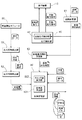
本発明による作業車の具体的な実施形態を説明する前に、図1と図2とを用いて、作業車による対地作業の時間管理に関する基本原理を説明する。図1には、対地作業を行っている作業車におけるデータの流れが示されており、図2には、作業車の走行経路と走行時間とが模式的に示されている。 Before describing a specific embodiment of the work vehicle according to the present invention, the basic principle regarding time management of ground work by the work vehicle will be described with reference to FIGS. 1 and 2. FIG. 1 shows a data flow in a work vehicle performing ground work, and FIG. 2 schematically shows a travel route and a travel time of the work vehicle.
ここでは、作業車は、図2に示すように操向輪や駆動輪などから構成される走行機構10を装備する車体1と、車体1に取り付けられた作業装置30とを備えている。図2の例では、作業車は、直進走行と180°の旋回走行とを繰り返しながら、作業地全体を作業走行する。作業車には、GNSSモジュールなどによって構成される衛星測位モジュール80が備えられており、車体の座標位置(以下単に自車位置と称する)を示す測位データを出力する。なお、測位データで表される自車位置は、アンテナの位置が基準となるが、ここでは、自車位置は、アンテナの位置ではなく、車両の適切な位置、例えば、作業装置30の対地作用点などとなるような位置補正処理が行われる。
Here, as shown in FIG. 2, the work vehicle includes a
図2で、模式的に示されているように、測位データに基づいて、走行距離算出部51は、周期的に取得した自車位置(又は走行時点)(図2ではP01・・・で示されている)から走行距離(図2ではL01・・・で示されている)を算出する。この周期的に連続して取得した自車位置を繋いでいくと、作業車の走行軌跡が得られる。また、走行距離を積算することにより、所定走行区間の走行距離、例えば全行程の走行距離が得られる。さらに、走行時間算出部52は、走行距離算出部51で算出された走行距離の走行に要した時間(図2ではt01・・・で示されている)を実距離走行時間として算出する。この実距離走行時間を積算することで、所定走行区間の実距離走行時間、例えば全行程の実距離走行時間が得られる。作業管理部50は、この作業車による対地作業の時間管理に、この実距離走行時間を用いる。
As schematically shown in FIG. 2, based on the positioning data, the travel
この作業車には、所定車速、例えば一定の車速(5km/hや10km/hなどの定車速)で走行しながら、この作業地を対地作業する際に必要となる目標走行時間を設定する目標走行時間設定部62が備えられている。これは、運転者が設定することもできるし、通信等の手段で自動的に設定されることも可能である。例えば、この作業車が、自動走行作業車として運用される場合には、経路設定部61によって設定された目標走行経路から、目標走行時間設定部62が目標走行時間を算出して、設定することも可能である。なお、直進走行での車速設定と旋回走行での車速設定とは、同一でなくてもよく、それぞれ別々に設定することができる。また、直進走行と旋回走行のいずれにおいても特定の区間において異なる車速を設定することも可能である。
The work vehicle has a target for setting a target travel time required for ground work on the work site while traveling at a predetermined vehicle speed, for example, a constant vehicle speed (a constant vehicle speed such as 5 km / h or 10 km / h). A travel
走行上のトラブル(走行機構10の不調、ぬかるみでのスリップなど)や作業上のトラブル(過負荷の発生など)があった場合、目標走行時間設定部62によって設定されている所定自車位置での目標走行時間と、走行時間算出部52によって算出される実距離走行時間と間の相違(時間ずれ)が、想定外に大きくなることがある。この場合には、作業車を停止して、走行機構10の状態や作業装置30の状態を点検する必要がある。したがって、作業管理部50は、目標走行時間と実距離走行時間との時間ずれが所定時間を超えた場合、緊急停止指令を出力させる機能を有する。この機能は、作業車が、自動走行作業車として運用される場合に、特に好適である。
When there is a trouble in traveling (such as a malfunction of the traveling
図1の例では、作業管理部50には、進捗度算出部501とスリップ率算出部502とが含まれている。進捗度算出部501は、この作業地に対する作業のために設定された目標走行時間と、走行時間算出部52によって算出された実距離走行時間(より詳しくは所定区間ごとの実距離走行時間の積算値)とを比較して、対地作業の進捗度を算出する。算出された進捗度は、視覚的な手段あるいは聴覚的な手段を通じて報知することができる。この進捗度の報知により、作業の進み具合(作業効率)、作業の残り時間(作業終了予測時間)などが容易に把握することができる。スリップ率算出部502は、目標走行時間と実距離走行時間との時間ずれに基づいて車体1のスリップ率を算出する。ぬかるみ面の走行時や小旋回半径での旋回走行時に生じるスリップは、一定車速での走行した場合での目標走行時間と実際の実距離走行時間との時間ずれとして現れるので、その時間ずれからスリップ率を算出することができる。このスリップ率により、作業地の地面状態や旋回状態などを評価することができる。
In the example of FIG. 1, the
この作業車のように、直進走行と旋回走行とを繰り返して作業地に対する作業を行っていく場合、直進走行で作業装置30を駆動し、旋回走行では作業装置30を駆動しないことが多い。また、直進走行と旋回走行とでは、走行機構10の状況が大きく異なる。このため、直進走行と旋回走行とを区分けして、走行管理あるいは作業管理することが好ましい。このため、この作業管理部50は、直進走行時における時間ずれを直進時間ずれとし、旋回走行時における時間ずれを旋回時間ずれとして算出する機能を有する。特に、直進走行と旋回走行とでは、走行負荷が大きく異なり、走行負荷に起因するスリップは、直進走行と旋回走行とでは区分けして評価することは、スリップ評価にとって重要である。このことから、スリップ率算出部502は、直進走行時における時間ずれから直進走行時のスリップ率である直進スリップ率を算出するとともに、旋回走行時における時間ずれから旋回走行時のスリップ率である旋回スリップ率を算出することも可能である。
In the case of performing work on the work place by repeating straight traveling and turning as in this work vehicle, the working
作業管理部50は、上述した以外の種々のデータ、例えば走行機構10の状態を示す走行データや作業装置30の状態を示す作業データも入力して、管理情報として記録することができる。さらに、作業管理部50で生成あるいは管理されている進捗度、時間ずれ、スリップ率、車体走行軌跡などのデータも管理情報として記録される。記録された管理情報は、記録メディアやデータ通信を通じて、作業車から持ち出すことができる。至急に報知した方がよい管理情報は、作業車の運転者や操作者に、視覚的あるいは聴覚的な手段を通じて直接報知される。
The
この作業車を自動走行として構成する場合には、経路設定部61によって設定される作業地における車体1の目標走行経路に自車位置が一致するように車体1を自動走行させる自動走行指令を生成する自動走行制御部42が備えられる。
When this work vehicle is configured as automatic travel, an automatic travel command for automatically traveling the
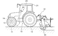
次に、本発明の作業車の具体的な実施形態の1つを説明する。この実施形態では、作業車は、図3に示されているように、畦によって境界づけられた圃場(作業地)に対して耕耘作業などの農作業を行うロータリ耕耘装置などの作業装置30を装備したトラクタである。このトラクタは、前輪11と後輪12とによって支持された車体1の中央部に操縦部20が設けられている。車体1の後部には油圧式の昇降機構31を介してロータリ耕耘装置である作業装置30が装備されている。前輪11は操向輪として機能し、その操舵角を変更することでトラクタの走行方向が変更される。前輪11の操舵角は操舵機構13の動作によって変更される。操舵機構13には自動操舵のための操舵モータ14が含まれている。手動走行の際には、操縦部20に配置されている前輪11の操舵はステアリングホイール22の操作によって可能である。トラクタのキャビン21には、GNSSモジュールとして構成されている衛星測位モジュール80が設けられている。図示されていないが、GPS信号やGNSS信号を受信するための衛星用アンテナがキャビン21の天井領域に取り付けられている。なお、衛星測位モジュール80には、衛星航法を補完するために、ジャイロ加速度センサや磁気方位センサを組み込んだ慣性航法モジュールを含めることができる。もちろん、慣性航法モジュールは、衛星測位モジュール80とは別の場所に設けてもよい。
Next, one specific embodiment of the work vehicle of the present invention will be described. In this embodiment, as shown in FIG. 3, the work vehicle is equipped with a working
図4には、このトラクタに構築されている制御系が示されている。この制御系は、図1を用いて説明された基本原理を採用している。この制御系の中核要素である制御ユニット4には、入出力インタフェースとして機能する、出力処理部7、入力処理部8、通信処理部70が備えられている。出力処理部7は、車両走行機器群71、作業走行機器群72、報知デバイス73などと接続している。車両走行機器群71には、操舵モータ14をはじめ、図示されていないが変速機構やエンジンユニットなど車両走行のために制御される機器が含まれている。作業走行機器群72には、作業装置30の駆動機構や、作業装置を昇降させる昇降機構31などが含まれている。通信処理部70は、制御ユニット4で処理されたデータを遠隔地の管理センタに構築された管理コンピュータ100に送信するとともに、管理コンピュータ100から種々のデータを受信する機能を有する。報知デバイス73には、フラットパネルディスプレイやランプやブザーが含まれており、走行注意情報や自動操舵走行での目標走行経路からの外れなど、運転者に報知したい種々の情報を視覚的または聴覚的の形態で運転者や操作者に対して報知する。報知デバイス73と出力処理部7との間の信号伝送は、有線または無線で行われる。
FIG. 4 shows a control system constructed in this tractor. This control system employs the basic principle described with reference to FIG. The
入力処理部8は、衛星測位モジュール80、走行系検出センサ群81、作業系検出センサ群82、自動/手動切替操作具83などと接続している。走行系検出センサ群81には、エンジン回転数や変速状態などの走行状態を検出するセンサが含まれている。作業系検出センサ群82には、作業装置30の位置や傾きを検出するセンサ、作業負荷などを検出するセンサなどが含まれている。自動/手動切替操作具83は、自動操舵で走行する自動走行モードと手動操舵で走行する手動操舵モードとのいずれかを選択するスイッチである。例えば、自動操舵モードで走行中に自動/手動切替操作具83を操作することで、手動操舵での走行に切り替えられ、動操舵での走行中に自動/手動切替操作具83を操作することで、自動操舵での走行に切り替えられる。
The
制御ユニット4には、図1を用いて既に説明した機能部である、走行制御部40、走行距離算出部51、走行時間算出部52、作業管理部50が備えられている。作業装置30を制御するために、作業制御部54が備えられている。このトラクタは、自動走行(自動操舵)と手動走行(手動操舵)の両方で走行可能である。このため、走行制御部40には、手動走行制御部41とともに自動走行制御部42が含まれる。この自動走行では、予め設定された目標走行経路に沿って走行するので、この目標走行経路を設定する経路設定部61、設定された目標走行経路の所定位置まで走行するまでの適正な時間である目標走行時間を設定する目標走行時間設定部62が備えられている。
The
目標走行経路の生成は、制御ユニット4または管理コンピュータ100あるいはその両方で行われる。制御ユニット4で、目標走行経路の作成を行う場合には、経路生成アルゴリズムを有する経路生成部63が制御ユニット4に備えられる。管理コンピュータ100で目標走行経路が生成される場合は、生成された目標走行経路が制御ユニット4に送られ、経路設定部61によって設定される。自動走行制御部42は、目標走行経路と自車位置との間の方位ずれ及び位置ずれを算出し、自動操舵指令を生成し、出力処理部7を介して操舵モータ14に出力する。走行制御部40を構成する手動走行制御部41及び自動走行制御部42のいずれもが、操作指示により、走行機構10に一定車速での走行を命じる定車速指令を与えることができる。これにより、自動走行と手動走行のいずれであっても、自動的に一定車速(直進走行と旋回走行とで異なる車速を採用してもよい)を維持して走行する定車速走行が可能である。
The generation of the target travel route is performed by the
この実施形態においても、作業管理部50には、図1を用いて説明した、進捗度算出部501及びスリップ率算出部502が備えられている。制御ユニット4に入力されたデータや制御ユニット4で生成されたデータは、記録部55に記録され、記録されたデータのなかで指定されたものは、リアルタイム処理またはバッジ処理で、管理コンピュータ100に転送される。
Also in this embodiment, the
作業管理部50で管理されている各種項目、例えば進捗度、スリップ率、自動走行時の方位ずれ及び位置ずれなどが、所定の許容範囲を超えた場合、報知デバイス73を通じて警報等を発するための報知データを生成する報知部56も備えられている。また、ボタンなどの操作によって、進捗度などは報知デバイス73を通じて報知させることも可能である。
When various items managed by the
トラクタの走行とともに、制御ユニット4で経時的に取り扱われるデータ群の一例が、図5に模式的なタイムチャートで示されている。走行地点を結んだトラクタの走行経路が、直線状で示されているが、その走行軌跡には直進経路や旋回経路が含まれている。つまり、図5の例では、走行地点P00からP04までが直進走行であり、P04からP05までが旋回走行であり、P05から再び直進走行と旋回走行が繰り返されている。
An example of a data group handled over time by the
図5で示された走行例では、所定の時点(T00・・・T06で示している)における自車位置である走行地点を、P00・・・P06で示しており、各走行地点の間の距離である走行距離を、L00・・・L06で示している。この走行距離は、衛星測位モジュール80からの測位データに基づいて算出されるので、各走行距離に必要とした走行時間(t00・・・t06で示している)はスリップなどの影響を受けていない実距離走行時間となる。
In the driving example shown in FIG. 5, the driving point that is the vehicle position at a predetermined point in time (indicated by T00... T06) is indicated by P00. The travel distance, which is a distance, is indicated by L00... L06. Since this travel distance is calculated based on the positioning data from the
各走行地点間の目標走行時間(rt00・・・rt06で示している)が目標走行時間設定部62で設定されている場合、目標走行時間と実走行距離時間との差である時間ずれが算出される。この時間ずれが許容範囲を超えた場合、警告の報知や走行停止が行われる。また、走行スタートからの実走行距離時間を積算することで、その時点までの積算実距離走行時間を算出することができる。この算出された積算実距離走行時間も目標の積算実距離走行時間との差が容範囲を超えた場合(時点T04)、警告の報知や走行停止が行われる。なお、図5では、各積算実距離走行時間が一定長さ(一定時間)で図示されているが、実際にはほとんど一定長さにはならない。
When the target travel time between each travel point (indicated by rt00... Rt06) is set by the target travel
実走行距離時間が目標走行時間を上回った場合、スリップが発生していると見なすことができるので、実走行距離時間と目標走行時間とからスリップ率(図5ではk01・・・k06で示している)が算出され、記録される。スリップ率が予め設定された許容限度を超えた場合、警告が報知される。もちろん、スリップ率は、後輪12の車軸回転数から算出される見かけの走行距離と、測位データに基づいて算出された走行距離とから、スリップ率の算出が可能であるので、スリップ率算出部502は、この方法で算出されたスリップ率を用いてもよい。
〔別実施の形態〕
If the actual travel distance exceeds the target travel time, it can be considered that a slip has occurred. Therefore, the slip rate (indicated by k01... K06 in FIG. 5) is calculated from the actual travel distance and the target travel time. Is calculated and recorded. When the slip ratio exceeds a preset allowable limit, a warning is notified. Of course, the slip ratio can be calculated from the apparent travel distance calculated from the axle rotational speed of the
[Another embodiment]
(1)上述した実施形態では、作業地走行での走行時間管理を実行する機能は、実質的に作業車に構築されていたが、これらの機能のいくつかは、作業車以外に、例えば管理コンピュータ100に分散することも可能である。そのような時間ベース管理システムの一例が図6に示されている。このシステムでは、目標走行経路を設定する経路設定部61、目標走行時間設定部62が、管理センタの管理コンピュータ100または管理者の通信端末に構築され、目標走行経路と目標走行時間とが作業車に転送される。実走行時間を算出する走行時間算出部52やスリップ率算出部502は、利用するデータの転送などの理由から作業車に構築されるのが好都合である。ただし、作業管理部50は、作業車または管理コンピュータまたは管理者の通信端末のいずれか都合のよい方に構築可能である。
(1) In the above-described embodiment, the function of executing the travel time management at the work site travel is substantially built in the work vehicle. However, some of these functions are managed, for example, in addition to the work vehicle. It can also be distributed to the
(2)上述した実施形態では、作業車として、ロータリ耕耘機を作業装置30として装備したトラクタを、作業車として取り上げたが、そのようなトラクタ以外にも、例えば、田植機、施肥機、コンバインなどの農作業車、あるいは作業装置30としてドーザやローラ等を備える建設作業車等の種々の作業車も、実施形態として採用することができる
(2) In the embodiment described above, a tractor equipped with a rotary tiller as the
(3)図1、図4、図6で示された機能ブロック図における各機能部は、主に説明目的で区分けされている。実際には、各機能部は他の機能部と統合または複数の機能部に分けることができる。 (3) The functional units in the functional block diagrams shown in FIGS. 1, 4, and 6 are divided mainly for the purpose of explanation. Actually, each functional unit can be integrated with other functional units or divided into a plurality of functional units.
本発明は、走行しながら対地作業を行う作業車に適用可能である。特に、目標走行経路に沿って、自動走行する自動走行作業車に好適である。 The present invention is applicable to a work vehicle that performs ground work while traveling. In particular, it is suitable for an automatic traveling work vehicle that automatically travels along a target travel route.
1 :車体
10 :走行機構
4 :制御ユニット
40 :走行制御部
41 :手動走行制御部
42 :自動走行制御部
50 :作業管理部
501 :進捗度算出部
502 :スリップ率算出部
51 :走行距離算出部
52 :走行時間算出部
54 :作業制御部
55 :記録部
56 :報知部
61 :経路設定部
62 :目標走行時間設定部
63 :経路生成部
7 :出力処理部
70 :通信処理部
73 :報知デバイス
8 :入力処理部
80 :衛星測位モジュール
1: Car body 10: Travel mechanism 4: Control unit 40: Travel control unit 41: Manual travel control unit 42: Automatic travel control unit 50: Work management unit 501: Progress degree calculation unit 502: Slip rate calculation unit 51: Travel distance calculation Unit 52: travel time calculation unit 54: work control unit 55: recording unit 56: notification unit 61: route setting unit 62: target travel time setting unit 63: route generation unit 7: output processing unit 70: communication processing unit 73: notification Device 8: Input processing unit 80: Satellite positioning module
Claims (12)
前記車体に装備され、作業地に対する対地作業を行う作業装置と、
測位データを出力する衛星測位モジュールと、
前記測位データに基づいて前記車体の走行距離を算出する走行距離算出部と、
前記走行距離算出部で算出された走行距離の走行に要した時間から実距離走行時間を算出する走行時間算出部と、
前記実距離走行時間に基づいて前記対地作業を管理する作業管理部と、
を備えた作業車。 A vehicle body equipped with a traveling mechanism;
A work device that is mounted on the vehicle body and that performs ground work on a work place;
A satellite positioning module that outputs positioning data;
A travel distance calculation unit that calculates the travel distance of the vehicle body based on the positioning data;
A travel time calculation unit that calculates an actual distance travel time from the time required for travel of the travel distance calculated by the travel distance calculation unit;
A work management unit for managing the ground work based on the actual distance travel time;
Work vehicle equipped with.
前記作業車による作業走行のための目標走行経路を設定する経路設定部と、
前記目標走行経路に沿って設定された複数の作業走行点に目標走行時間を割り当てる目標走行時間設定部と、
前記作業車の実際の作業走行時の前記作業走行点における経過時間を実走行時間として算出する走行時間算出部と、
前記作業走行点における前記目標走行時間と前記実走行時間とを比較評価する作業管理部と、
を備えた作業車のための時間ベース管理システム。 A time-based management system for a work vehicle equipped with a work device that performs ground work on a vehicle body equipped with a traveling mechanism,
A route setting unit for setting a target travel route for work travel by the work vehicle;
A target travel time setting unit that assigns a target travel time to a plurality of work travel points set along the target travel route;
A travel time calculation unit that calculates an elapsed time at the work travel point during actual work travel of the work vehicle as an actual travel time;
A work management unit that compares and evaluates the target travel time and the actual travel time at the work travel point;
Time-based management system for work vehicles equipped with.
前記目標走行時間と前記実走行時間との相違を示す相違値が、所定のしきい値を超えた場合、前記相違に対する前記スリップ率の影響が評価される請求項10または11に記載の作業車のための時間ベース管理システム。 A slip ratio calculating section for calculating a slip ratio of the vehicle body, and when a difference value indicating a difference between the target travel time and the actual travel time exceeds a predetermined threshold, the slip for the difference 12. A time-based management system for a work vehicle according to claim 10 or 11, wherein the influence of the rate is evaluated.
Priority Applications (6)
| Application Number | Priority Date | Filing Date | Title |
|---|---|---|---|
| JP2016105365A JP6697955B2 (en) | 2016-05-26 | 2016-05-26 | Work vehicles and time-based management systems applied to work vehicles |
| US16/093,678 US11144061B2 (en) | 2016-05-26 | 2016-12-06 | Work vehicle and time-based management system applicable to the work vehicle |
| EP16903212.5A EP3466232B1 (en) | 2016-05-26 | 2016-12-06 | Work vehicle and time-based management system applicable to the work vehicle |
| PCT/JP2016/086232 WO2017203733A1 (en) | 2016-05-26 | 2016-12-06 | Work vehicle, and time-based management system applicable to said work vehicle |
| CN201680084238.4A CN109068576B (en) | 2016-05-26 | 2016-12-06 | Work vehicle and time-based management system applied to work vehicle |
| JP2020077587A JP6972225B2 (en) | 2016-05-26 | 2020-04-24 | Time-based management system |
Applications Claiming Priority (1)
| Application Number | Priority Date | Filing Date | Title |
|---|---|---|---|
| JP2016105365A JP6697955B2 (en) | 2016-05-26 | 2016-05-26 | Work vehicles and time-based management systems applied to work vehicles |
Related Child Applications (1)
| Application Number | Title | Priority Date | Filing Date |
|---|---|---|---|
| JP2020077587A Division JP6972225B2 (en) | 2016-05-26 | 2020-04-24 | Time-based management system |
Publications (2)
| Publication Number | Publication Date |
|---|---|
| JP2017209070A true JP2017209070A (en) | 2017-11-30 |
| JP6697955B2 JP6697955B2 (en) | 2020-05-27 |
Family
ID=60411223
Family Applications (1)
| Application Number | Title | Priority Date | Filing Date |
|---|---|---|---|
| JP2016105365A Active JP6697955B2 (en) | 2016-05-26 | 2016-05-26 | Work vehicles and time-based management systems applied to work vehicles |
Country Status (5)
| Country | Link |
|---|---|
| US (1) | US11144061B2 (en) |
| EP (1) | EP3466232B1 (en) |
| JP (1) | JP6697955B2 (en) |
| CN (1) | CN109068576B (en) |
| WO (1) | WO2017203733A1 (en) |
Cited By (5)
| Publication number | Priority date | Publication date | Assignee | Title |
|---|---|---|---|---|
| JP2019121267A (en) * | 2018-01-10 | 2019-07-22 | ヤンマー株式会社 | Travel speed control device |
| JP2020198789A (en) * | 2019-06-06 | 2020-12-17 | 井関農機株式会社 | Autonomously traveling work vehicle |
| JP2021007335A (en) * | 2019-06-28 | 2021-01-28 | 株式会社クボタ | Work vehicle |
| JP2022033560A (en) * | 2020-08-17 | 2022-03-02 | 井関農機株式会社 | Work vehicle |
| JP7438851B2 (en) | 2020-06-01 | 2024-02-27 | 本田技研工業株式会社 | Mobile object control device, mobile object, mobile object management system, mobile object control method, and program |
Families Citing this family (5)
| Publication number | Priority date | Publication date | Assignee | Title |
|---|---|---|---|---|
| DE102015010726A1 (en) * | 2015-08-17 | 2017-02-23 | Liebherr-Werk Biberach Gmbh | Site monitoring procedure, work machine and site monitoring system |
| US11016501B2 (en) * | 2017-01-23 | 2021-05-25 | Built Robotics Inc. | Mapping a dig site diagram |
| US11386373B2 (en) * | 2017-03-31 | 2022-07-12 | Nec Corporation | Work management device, work management method, and program storage medium |
| US10820508B2 (en) * | 2018-08-20 | 2020-11-03 | Cnh Industrial America Llc | System and method for operating an agricultural harvester |
| US20220287218A1 (en) * | 2021-03-15 | 2022-09-15 | Kubota Corporation | Work vehicle and control system for work vehicle |
Citations (5)
| Publication number | Priority date | Publication date | Assignee | Title |
|---|---|---|---|---|
| JPS63148909A (en) * | 1986-12-11 | 1988-06-21 | 井関農機株式会社 | Automatic steering control apparatus in harvester |
| JP2002358122A (en) * | 2001-05-31 | 2002-12-13 | Yanmar Agricult Equip Co Ltd | Agricultural work vehicle |
| JP2010142185A (en) * | 2008-12-20 | 2010-07-01 | Iseki & Co Ltd | Autonomously traveling seedling transplanter |
| JP2010187558A (en) * | 2009-02-16 | 2010-09-02 | Iseki & Co Ltd | Variable spray apparatus |
| WO2016076289A1 (en) * | 2014-11-13 | 2016-05-19 | ヤンマー株式会社 | Agricultural work vehicle |
Family Cites Families (101)
| Publication number | Priority date | Publication date | Assignee | Title |
|---|---|---|---|---|
| JP2566745B2 (en) * | 1994-04-29 | 1996-12-25 | 三星重工業株式会社 | Automatic flat working method of electronically controlled hydraulic excavator |
| EP0891913B1 (en) * | 1997-01-23 | 2008-08-20 | Yanmar Agricultural Equipment Co., Ltd. | Mobile agricultural machine |
| US6108949A (en) * | 1997-12-19 | 2000-08-29 | Carnegie Mellon University | Method and apparatus for determining an excavation strategy |
| US6523765B1 (en) * | 1998-03-18 | 2003-02-25 | Hitachi Construction Machinery Co., Ltd. | Automatically operated shovel and stone crushing system comprising the same |
| US6167336A (en) * | 1998-05-18 | 2000-12-26 | Carnegie Mellon University | Method and apparatus for determining an excavation strategy for a front-end loader |
| US6363632B1 (en) * | 1998-10-09 | 2002-04-02 | Carnegie Mellon University | System for autonomous excavation and truck loading |
| US6823616B1 (en) * | 2001-07-06 | 2004-11-30 | Boskalis Westminister Inc. | Method of excavating |
| JP2003303021A (en) | 2002-04-10 | 2003-10-24 | Mitsubishi Agricult Mach Co Ltd | Traveling vehicle for working |
| US6711838B2 (en) * | 2002-07-29 | 2004-03-30 | Caterpillar Inc | Method and apparatus for determining machine location |
| JP2005315768A (en) * | 2004-04-30 | 2005-11-10 | National Agriculture & Bio-Oriented Research Organization | Measuring system using gps signal as trigger |
| US6901319B1 (en) | 2004-07-06 | 2005-05-31 | Deere & Company | System and method for controlling a ground vehicle |
| US7627410B2 (en) * | 2005-12-12 | 2009-12-01 | Caterpillar Inc. | Machine payload measurement dial-a-load system |
| US20070240341A1 (en) * | 2006-04-12 | 2007-10-18 | Esco Corporation | UDD dragline bucket machine and control system |
| US7509198B2 (en) * | 2006-06-23 | 2009-03-24 | Caterpillar Inc. | System for automated excavation entry point selection |
| US7853382B2 (en) * | 2006-09-29 | 2010-12-14 | Deere & Company | Loader boom control system |
| US7516563B2 (en) * | 2006-11-30 | 2009-04-14 | Caterpillar Inc. | Excavation control system providing machine placement recommendation |
| WO2008113098A1 (en) * | 2007-03-21 | 2008-09-25 | Commonwealth Scientific And Industrial Reserach Organisation | Method for planning and executing obstacle-free paths for rotating excavation machinery |
| US7832126B2 (en) * | 2007-05-17 | 2010-11-16 | Siemens Industry, Inc. | Systems, devices, and/or methods regarding excavating |
| DE202007008557U1 (en) * | 2007-06-19 | 2008-10-30 | Liebherr-Werk Bischofshofen Ges.M.B.H. | System for automatically moving material |
| US7711842B2 (en) * | 2007-06-29 | 2010-05-04 | Caterpillar Inc. | System and method for remote machine data transfer |
| JP4998324B2 (en) * | 2008-02-26 | 2012-08-15 | 井関農機株式会社 | Traveling vehicle |
| DE102008015277A1 (en) * | 2008-03-20 | 2009-09-24 | Deere & Company, Moline | Method and device for steering a second agricultural machine, which is steerable over a field relative to a first agricultural machine |
| JP2010187588A (en) | 2009-02-17 | 2010-09-02 | Kao Corp | METHOD FOR PRODUCING alpha-AMYLASE |
| JP2012029600A (en) * | 2010-07-29 | 2012-02-16 | Iseki & Co Ltd | Seedling transplanter |
| US8639393B2 (en) * | 2010-11-30 | 2014-01-28 | Caterpillar Inc. | System for automated excavation planning and control |
| US20120253709A1 (en) * | 2010-12-30 | 2012-10-04 | Agco Corporation | Automatic Detection of Machine Status for Fleet Management |
| US8655505B2 (en) * | 2011-02-18 | 2014-02-18 | Caterpillar Inc. | Worksite management system implementing remote machine reconfiguration |
| JP5727822B2 (en) * | 2011-03-15 | 2015-06-03 | 株式会社クボタ | Tractor |
| CN103004340B (en) * | 2011-09-20 | 2017-04-12 | 井关农机株式会社 | Seedling transplanting machine |
| US9206587B2 (en) * | 2012-03-16 | 2015-12-08 | Harnischfeger Technologies, Inc. | Automated control of dipper swing for a shovel |
| JP5597222B2 (en) * | 2012-04-11 | 2014-10-01 | 株式会社小松製作所 | Excavator drilling control system |
| US8620535B2 (en) * | 2012-05-21 | 2013-12-31 | Caterpillar Inc. | System for automated excavation planning and control |
| ITMI20120922A1 (en) * | 2012-05-28 | 2013-11-29 | Snowgrolic S A R L | CONTROL METHOD, PROGRAM FOR ELECTRONIC PROCESSORS AND CONTROL DEVICE FOR A TRACKED VEHICLE |
| US20140012404A1 (en) * | 2012-07-06 | 2014-01-09 | Caterpillar Inc. | Methods and systems for machine cut planning |
| US9234750B2 (en) * | 2012-07-30 | 2016-01-12 | Caterpillar Inc. | System and method for operating a machine |
| US20140064897A1 (en) * | 2012-08-29 | 2014-03-06 | Deere And Company | Single stick operation of a work tool |
| AU2013227999A1 (en) * | 2012-09-13 | 2014-03-27 | Technological Resources Pty Ltd | A system for, and a method of, controlling operation of a vehicle in a defined area |
| US8838331B2 (en) * | 2012-09-21 | 2014-09-16 | Caterpillar Inc. | Payload material density calculation and machine using same |
| US8755977B2 (en) * | 2012-09-21 | 2014-06-17 | Siemens Industry, Inc. | Method and system for preemptive load weight for mining excavating equipment |
| US9014922B2 (en) * | 2012-12-20 | 2015-04-21 | Caterpillar Inc. | System and method for optimizing a cut location |
| US8948981B2 (en) * | 2012-12-20 | 2015-02-03 | Caterpillar Inc. | System and method for optimizing a cut location |
| US20140277905A1 (en) * | 2013-03-15 | 2014-09-18 | Deere & Company | Methods and apparatus to manage a fleet of work machines |
| JP6238615B2 (en) * | 2013-07-22 | 2017-11-29 | 株式会社クボタ | Wheel-driven work vehicle |
| EP2901400A4 (en) * | 2013-09-23 | 2015-12-02 | Farmobile Llc | Farming data collection and exchange system |
| CN105102729B (en) * | 2013-11-15 | 2017-03-08 | 株式会社小松制作所 | Working truck and its control method |
| US10380704B2 (en) * | 2014-01-14 | 2019-08-13 | Deere & Company | Operator performance recommendation generation |
| CN110806753B (en) * | 2014-02-06 | 2023-08-29 | 洋马动力科技有限公司 | Parallel travel work system |
| KR102472494B1 (en) * | 2014-03-28 | 2022-11-29 | 얀마 파워 테크놀로지 가부시키가이샤 | Autonomous travelling service vehicle |
| US9267837B2 (en) * | 2014-03-31 | 2016-02-23 | Siemens Industry, Inc. | Methods and systems for active load weight for mining excavating equipment |
| DE112014000027B4 (en) * | 2014-04-24 | 2016-05-19 | Komatsu Ltd. | working vehicle |
| US9454155B2 (en) * | 2014-06-02 | 2016-09-27 | Trimble Navigation Limited | Implement guidance |
| US9404239B2 (en) * | 2014-06-09 | 2016-08-02 | Caterpillar Inc. | Sub-bin refinement for autonomous machines |
| AU2014203829A1 (en) * | 2014-07-11 | 2016-01-28 | Caterpillar Of Australia Pty Ltd | System and method for determining machine operational state |
| US9891605B2 (en) * | 2014-08-06 | 2018-02-13 | Caterpillar Inc. | Grade control cleanup pass using volume constraints |
| US10109024B2 (en) * | 2014-09-05 | 2018-10-23 | The Climate Corporation | Collecting data to generate an agricultural prescription |
| US9360334B2 (en) * | 2014-09-12 | 2016-06-07 | Caterpillar Inc. | System and method for setting an end location of a path |
| US9388550B2 (en) * | 2014-09-12 | 2016-07-12 | Caterpillar Inc. | System and method for controlling the operation of a machine |
| US9228321B1 (en) * | 2014-09-12 | 2016-01-05 | Caterpillar Inc. | System and method for adjusting the operation of a machine |
| US20160076222A1 (en) * | 2014-09-12 | 2016-03-17 | Caterpillar Inc. | System and Method for Optimizing a Work Implement Path |
| US9605415B2 (en) * | 2014-09-12 | 2017-03-28 | Caterpillar Inc. | System and method for monitoring a machine |
| US9469967B2 (en) * | 2014-09-12 | 2016-10-18 | Caterpillar Inc. | System and method for controlling the operation of a machine |
| US9760081B2 (en) * | 2014-09-12 | 2017-09-12 | Caterpillar Inc. | System and method for optimizing a work implement path |
| US9256227B1 (en) * | 2014-09-12 | 2016-02-09 | Caterpillar Inc. | System and method for controlling the operation of a machine |
| US9297147B1 (en) * | 2014-09-30 | 2016-03-29 | Caterpillar Inc. | Semi-autonomous tractor system crest ramp removal |
| US10563376B2 (en) * | 2014-10-13 | 2020-02-18 | Sandvik Mining And Construction Oy | Arrangement for controlling a work machine |
| US20160201298A1 (en) * | 2015-01-08 | 2016-07-14 | Caterpillar Inc. | Systems and Methods for Constrained Dozing |
| AR105551A1 (en) * | 2015-04-07 | 2017-10-18 | Gates Corp | SYSTEM AND METHOD OF MANAGEMENT OF THE LIFE CYCLE OF A PRODUCT |
| US9563867B2 (en) * | 2015-04-13 | 2017-02-07 | Caterpillar Inc. | System for allocating and monitoring machines |
| US10186004B2 (en) * | 2015-05-20 | 2019-01-22 | Caterpillar Inc. | System and method for evaluating a material movement plan |
| US9587369B2 (en) * | 2015-07-02 | 2017-03-07 | Caterpillar Inc. | Excavation system having adaptive dig control |
| US9974225B2 (en) * | 2016-01-14 | 2018-05-22 | Cnh Industrial America Llc | System and method for generating and implementing an end-of-row turn path |
| US9968025B2 (en) * | 2016-01-14 | 2018-05-15 | CNH Industrial American LLC | System and method for generating and implementing an end-of-row turn path |
| CN107343381A (en) * | 2016-03-01 | 2017-11-10 | 株式会社小松制作所 | Evaluating apparatus and evaluation method |
| US10066367B1 (en) * | 2016-06-20 | 2018-09-04 | Robo Industries, Inc. | System for determining autonomous adjustments to an implement position and angle |
| JP2018021345A (en) * | 2016-08-02 | 2018-02-08 | 株式会社小松製作所 | Work vehicle control system, control method, and work vehicle |
| JP2018021346A (en) * | 2016-08-02 | 2018-02-08 | 株式会社小松製作所 | Work vehicle control system, control method, and work vehicle |
| JP2018021348A (en) * | 2016-08-02 | 2018-02-08 | 株式会社小松製作所 | Work vehicle control system, control method, and work vehicle |
| JP2018021347A (en) * | 2016-08-02 | 2018-02-08 | 株式会社小松製作所 | Work vehicle control system, control method, and work vehicle |
| JP7122800B2 (en) * | 2016-08-05 | 2022-08-22 | 株式会社小松製作所 | WORK VEHICLE CONTROL SYSTEM, CONTROL METHOD, AND WORK VEHICLE |
| US10860016B1 (en) * | 2016-09-07 | 2020-12-08 | Robo Industries, Inc. | Automated site based mission planning system |
| US10234368B2 (en) * | 2016-10-13 | 2019-03-19 | Deere & Company | System and method for load evaluation |
| US11016501B2 (en) * | 2017-01-23 | 2021-05-25 | Built Robotics Inc. | Mapping a dig site diagram |
| US10267018B2 (en) * | 2017-01-27 | 2019-04-23 | Deere & Company | Work vehicle load control system and method |
| CA2991823C (en) * | 2017-01-31 | 2020-04-28 | Kazuhiro Hashimoto | Control system for work vehicle, and method for setting trajectory of work implement |
| US10850734B2 (en) * | 2017-04-03 | 2020-12-01 | Motional Ad Llc | Processing a request signal regarding operation of an autonomous vehicle |
| US10479354B2 (en) * | 2017-05-02 | 2019-11-19 | Cnh Industrial America Llc | Obstacle detection system for a work vehicle |
| US10208453B2 (en) * | 2017-05-16 | 2019-02-19 | Caterpillar Inc. | Methods and systems for monitoring work zone in worksite |
| US10151078B1 (en) * | 2017-05-23 | 2018-12-11 | Caterpillar Trimble Control Technologies Llc | Blade control below design |
| US10407878B2 (en) * | 2017-05-23 | 2019-09-10 | Caterpillar Inc. | System and method for dumping material |
| US10472803B2 (en) * | 2017-08-07 | 2019-11-12 | Caterpillar Inc. | System and method for determining stale terrain value of worksite |
| JP6868938B2 (en) * | 2017-08-24 | 2021-05-12 | 日立建機株式会社 | Construction machinery load measurement system |
| US20190101641A1 (en) * | 2017-10-04 | 2019-04-04 | Caterpillar Paving Products Inc. | Work tool collision avoidance system for underground objects |
| US10738439B2 (en) * | 2018-01-19 | 2020-08-11 | Deere & Company | Open loop electrohydraulic bucket position control method and system |
| US20200019192A1 (en) * | 2018-07-13 | 2020-01-16 | Caterpillar Paving Products Inc. | Object detection and implement position detection system |
| US20200032490A1 (en) * | 2018-07-26 | 2020-01-30 | Built Robotics Inc. | Filling earth at a location within a dig site using an excavation vehicle |
| US10794039B2 (en) * | 2018-08-08 | 2020-10-06 | Caterpillar Inc. | System and method for controlling the operation of a machine |
| US10820508B2 (en) * | 2018-08-20 | 2020-11-03 | Cnh Industrial America Llc | System and method for operating an agricultural harvester |
| US11041291B2 (en) * | 2018-09-14 | 2021-06-22 | Deere & Company | Controlling a work machine based on sensed variables |
| US10774506B2 (en) * | 2018-09-28 | 2020-09-15 | Caterpillar Inc. | System and method for controlling the operation of a machine |
| US10832435B1 (en) * | 2019-04-26 | 2020-11-10 | Caterpillar Inc. | Determining payload carrier volume using a neural network |
| US10849264B1 (en) * | 2019-05-21 | 2020-12-01 | Farmobile Llc | Determining activity swath from machine-collected worked data |
-
2016
- 2016-05-26 JP JP2016105365A patent/JP6697955B2/en active Active
- 2016-12-06 EP EP16903212.5A patent/EP3466232B1/en active Active
- 2016-12-06 CN CN201680084238.4A patent/CN109068576B/en active Active
- 2016-12-06 US US16/093,678 patent/US11144061B2/en active Active
- 2016-12-06 WO PCT/JP2016/086232 patent/WO2017203733A1/en unknown
Patent Citations (5)
| Publication number | Priority date | Publication date | Assignee | Title |
|---|---|---|---|---|
| JPS63148909A (en) * | 1986-12-11 | 1988-06-21 | 井関農機株式会社 | Automatic steering control apparatus in harvester |
| JP2002358122A (en) * | 2001-05-31 | 2002-12-13 | Yanmar Agricult Equip Co Ltd | Agricultural work vehicle |
| JP2010142185A (en) * | 2008-12-20 | 2010-07-01 | Iseki & Co Ltd | Autonomously traveling seedling transplanter |
| JP2010187558A (en) * | 2009-02-16 | 2010-09-02 | Iseki & Co Ltd | Variable spray apparatus |
| WO2016076289A1 (en) * | 2014-11-13 | 2016-05-19 | ヤンマー株式会社 | Agricultural work vehicle |
Cited By (9)
| Publication number | Priority date | Publication date | Assignee | Title |
|---|---|---|---|---|
| JP2019121267A (en) * | 2018-01-10 | 2019-07-22 | ヤンマー株式会社 | Travel speed control device |
| JP2021176094A (en) * | 2018-01-10 | 2021-11-04 | ヤンマーパワーテクノロジー株式会社 | Travel speed control apparatus |
| JP2020198789A (en) * | 2019-06-06 | 2020-12-17 | 井関農機株式会社 | Autonomously traveling work vehicle |
| JP7192667B2 (en) | 2019-06-06 | 2022-12-20 | 井関農機株式会社 | Autonomous working vehicle |
| JP2021007335A (en) * | 2019-06-28 | 2021-01-28 | 株式会社クボタ | Work vehicle |
| JP7159121B2 (en) | 2019-06-28 | 2022-10-24 | 株式会社クボタ | work vehicle |
| JP7438851B2 (en) | 2020-06-01 | 2024-02-27 | 本田技研工業株式会社 | Mobile object control device, mobile object, mobile object management system, mobile object control method, and program |
| JP2022033560A (en) * | 2020-08-17 | 2022-03-02 | 井関農機株式会社 | Work vehicle |
| JP7259814B2 (en) | 2020-08-17 | 2023-04-18 | 井関農機株式会社 | work vehicle |
Also Published As
| Publication number | Publication date |
|---|---|
| CN109068576B (en) | 2021-07-13 |
| WO2017203733A1 (en) | 2017-11-30 |
| EP3466232A4 (en) | 2020-01-15 |
| CN109068576A (en) | 2018-12-21 |
| US20190072972A1 (en) | 2019-03-07 |
| EP3466232B1 (en) | 2022-04-27 |
| EP3466232A1 (en) | 2019-04-10 |
| JP6697955B2 (en) | 2020-05-27 |
| US11144061B2 (en) | 2021-10-12 |
Similar Documents
| Publication | Publication Date | Title |
|---|---|---|
| WO2017203733A1 (en) | Work vehicle, and time-based management system applicable to said work vehicle | |
| JP7354217B2 (en) | automatic work system | |
| US10474153B2 (en) | Work vehicle, slope travel control system for work vehicle, and slope travel control method for work vehicle | |
| KR102140854B1 (en) | Method for setting travel path of autonomous travel work vehicle | |
| JP2022022285A (en) | Control system | |
| US9605415B2 (en) | System and method for monitoring a machine | |
| US20140170617A1 (en) | Monitoring System for a Machine | |
| WO2015119265A1 (en) | Travel control system | |
| WO2015118731A1 (en) | Control device for parallel travel work system | |
| US11937526B2 (en) | Control device for work vehicle configured to travel autonomously | |
| WO2018146955A1 (en) | Satellite-radio-wave-sensitivity distribution management system and method for work vehicle | |
| JP2022016479A (en) | Skid determination system | |
| JP2020074127A (en) | Work vehicle cooperation system | |
| JP6921935B2 (en) | Field work vehicle | |
| JP2018198582A (en) | Automatic traveling work vehicle | |
| JP6972225B2 (en) | Time-based management system | |
| JP2020126307A (en) | Target route generation system for work vehicle | |
| KR102496210B1 (en) | Method for adjusting the reference value for straight-line driving of agricultural vehicle | |
| WO2023119993A1 (en) | Field working machine | |
| US20230251669A1 (en) | Path determination for automatic mowers | |
| EP3901722A1 (en) | Travel state display device and automated travel system | |
| JP2020162605A (en) | Implement | |
| JP2019217921A (en) | Work vehicle |
Legal Events
| Date | Code | Title | Description |
|---|---|---|---|
| A621 | Written request for application examination |
Free format text: JAPANESE INTERMEDIATE CODE: A621 Effective date: 20180626 |
|
| A131 | Notification of reasons for refusal |
Free format text: JAPANESE INTERMEDIATE CODE: A131 Effective date: 20190604 |
|
| A521 | Request for written amendment filed |
Free format text: JAPANESE INTERMEDIATE CODE: A523 Effective date: 20190724 |
|
| A131 | Notification of reasons for refusal |
Free format text: JAPANESE INTERMEDIATE CODE: A131 Effective date: 20200107 |
|
| A521 | Request for written amendment filed |
Free format text: JAPANESE INTERMEDIATE CODE: A523 Effective date: 20200306 |
|
| TRDD | Decision of grant or rejection written | ||
| A01 | Written decision to grant a patent or to grant a registration (utility model) |
Free format text: JAPANESE INTERMEDIATE CODE: A01 Effective date: 20200331 |
|
| A61 | First payment of annual fees (during grant procedure) |
Free format text: JAPANESE INTERMEDIATE CODE: A61 Effective date: 20200427 |
|
| R150 | Certificate of patent or registration of utility model |
Ref document number: 6697955 Country of ref document: JP Free format text: JAPANESE INTERMEDIATE CODE: R150 |