JP2017207446A - Total reflection spectroscopic measurement apparatus and total reflection spectroscopic measurement method - Google Patents
Total reflection spectroscopic measurement apparatus and total reflection spectroscopic measurement method Download PDFInfo
- Publication number
- JP2017207446A JP2017207446A JP2016101709A JP2016101709A JP2017207446A JP 2017207446 A JP2017207446 A JP 2017207446A JP 2016101709 A JP2016101709 A JP 2016101709A JP 2016101709 A JP2016101709 A JP 2016101709A JP 2017207446 A JP2017207446 A JP 2017207446A
- Authority
- JP
- Japan
- Prior art keywords
- total reflection
- terahertz wave
- electric field
- measured
- field vector
- Prior art date
- Legal status (The legal status is an assumption and is not a legal conclusion. Google has not performed a legal analysis and makes no representation as to the accuracy of the status listed.)
- Granted
Links
- 238000005259 measurement Methods 0.000 title claims abstract description 53
- 238000000691 measurement method Methods 0.000 title claims description 16
- 230000005684 electric field Effects 0.000 claims abstract description 78
- 239000013598 vector Substances 0.000 claims abstract description 76
- 238000001514 detection method Methods 0.000 claims abstract description 54
- 230000003287 optical effect Effects 0.000 claims abstract description 54
- 230000010287 polarization Effects 0.000 claims abstract description 49
- 238000004458 analytical method Methods 0.000 claims abstract description 22
- 238000000034 method Methods 0.000 claims description 6
- 238000001055 reflectance spectroscopy Methods 0.000 claims description 5
- 230000001902 propagating effect Effects 0.000 claims 1
- 239000000523 sample Substances 0.000 description 42
- 239000013078 crystal Substances 0.000 description 9
- 238000010586 diagram Methods 0.000 description 6
- 229910007709 ZnTe Inorganic materials 0.000 description 3
- 238000010521 absorption reaction Methods 0.000 description 2
- 239000011248 coating agent Substances 0.000 description 2
- 238000000576 coating method Methods 0.000 description 2
- 238000004891 communication Methods 0.000 description 2
- 238000005516 engineering process Methods 0.000 description 2
- 229910001218 Gallium arsenide Inorganic materials 0.000 description 1
- 101000655352 Homo sapiens Telomerase reverse transcriptase Proteins 0.000 description 1
- 229910000673 Indium arsenide Inorganic materials 0.000 description 1
- 102100032938 Telomerase reverse transcriptase Human genes 0.000 description 1
- 238000005102 attenuated total reflection Methods 0.000 description 1
- 238000004364 calculation method Methods 0.000 description 1
- 230000001427 coherent effect Effects 0.000 description 1
- 238000002425 crystallisation Methods 0.000 description 1
- 230000008025 crystallization Effects 0.000 description 1
- 230000001934 delay Effects 0.000 description 1
- 230000003111 delayed effect Effects 0.000 description 1
- 230000000694 effects Effects 0.000 description 1
- 230000007613 environmental effect Effects 0.000 description 1
- RPQDHPTXJYYUPQ-UHFFFAOYSA-N indium arsenide Chemical compound [In]#[As] RPQDHPTXJYYUPQ-UHFFFAOYSA-N 0.000 description 1
- 238000012544 monitoring process Methods 0.000 description 1
- 239000004065 semiconductor Substances 0.000 description 1
- 230000035945 sensitivity Effects 0.000 description 1
- 238000004611 spectroscopical analysis Methods 0.000 description 1
- 239000002887 superconductor Substances 0.000 description 1
Images


Classifications
-
- G—PHYSICS
- G01—MEASURING; TESTING
- G01J—MEASUREMENT OF INTENSITY, VELOCITY, SPECTRAL CONTENT, POLARISATION, PHASE OR PULSE CHARACTERISTICS OF INFRARED, VISIBLE OR ULTRAVIOLET LIGHT; COLORIMETRY; RADIATION PYROMETRY
- G01J3/00—Spectrometry; Spectrophotometry; Monochromators; Measuring colours
- G01J3/28—Investigating the spectrum
-
- G—PHYSICS
- G01—MEASURING; TESTING
- G01J—MEASUREMENT OF INTENSITY, VELOCITY, SPECTRAL CONTENT, POLARISATION, PHASE OR PULSE CHARACTERISTICS OF INFRARED, VISIBLE OR ULTRAVIOLET LIGHT; COLORIMETRY; RADIATION PYROMETRY
- G01J3/00—Spectrometry; Spectrophotometry; Monochromators; Measuring colours
- G01J3/12—Generating the spectrum; Monochromators
- G01J3/14—Generating the spectrum; Monochromators using refracting elements, e.g. prisms
-
- G—PHYSICS
- G01—MEASURING; TESTING
- G01J—MEASUREMENT OF INTENSITY, VELOCITY, SPECTRAL CONTENT, POLARISATION, PHASE OR PULSE CHARACTERISTICS OF INFRARED, VISIBLE OR ULTRAVIOLET LIGHT; COLORIMETRY; RADIATION PYROMETRY
- G01J3/00—Spectrometry; Spectrophotometry; Monochromators; Measuring colours
- G01J3/02—Details
- G01J3/0205—Optical elements not provided otherwise, e.g. optical manifolds, diffusers, windows
- G01J3/0224—Optical elements not provided otherwise, e.g. optical manifolds, diffusers, windows using polarising or depolarising elements
-
- G—PHYSICS
- G01—MEASURING; TESTING
- G01J—MEASUREMENT OF INTENSITY, VELOCITY, SPECTRAL CONTENT, POLARISATION, PHASE OR PULSE CHARACTERISTICS OF INFRARED, VISIBLE OR ULTRAVIOLET LIGHT; COLORIMETRY; RADIATION PYROMETRY
- G01J3/00—Spectrometry; Spectrophotometry; Monochromators; Measuring colours
- G01J3/28—Investigating the spectrum
- G01J3/42—Absorption spectrometry; Double beam spectrometry; Flicker spectrometry; Reflection spectrometry
-
- G—PHYSICS
- G01—MEASURING; TESTING
- G01J—MEASUREMENT OF INTENSITY, VELOCITY, SPECTRAL CONTENT, POLARISATION, PHASE OR PULSE CHARACTERISTICS OF INFRARED, VISIBLE OR ULTRAVIOLET LIGHT; COLORIMETRY; RADIATION PYROMETRY
- G01J3/00—Spectrometry; Spectrophotometry; Monochromators; Measuring colours
- G01J3/28—Investigating the spectrum
- G01J3/447—Polarisation spectrometry
-
- G—PHYSICS
- G01—MEASURING; TESTING
- G01N—INVESTIGATING OR ANALYSING MATERIALS BY DETERMINING THEIR CHEMICAL OR PHYSICAL PROPERTIES
- G01N21/00—Investigating or analysing materials by the use of optical means, i.e. using sub-millimetre waves, infrared, visible or ultraviolet light
- G01N21/17—Systems in which incident light is modified in accordance with the properties of the material investigated
- G01N21/25—Colour; Spectral properties, i.e. comparison of effect of material on the light at two or more different wavelengths or wavelength bands
- G01N21/255—Details, e.g. use of specially adapted sources, lighting or optical systems
-
- G—PHYSICS
- G01—MEASURING; TESTING
- G01N—INVESTIGATING OR ANALYSING MATERIALS BY DETERMINING THEIR CHEMICAL OR PHYSICAL PROPERTIES
- G01N21/00—Investigating or analysing materials by the use of optical means, i.e. using sub-millimetre waves, infrared, visible or ultraviolet light
- G01N21/17—Systems in which incident light is modified in accordance with the properties of the material investigated
- G01N21/25—Colour; Spectral properties, i.e. comparison of effect of material on the light at two or more different wavelengths or wavelength bands
- G01N21/31—Investigating relative effect of material at wavelengths characteristic of specific elements or molecules, e.g. atomic absorption spectrometry
- G01N21/35—Investigating relative effect of material at wavelengths characteristic of specific elements or molecules, e.g. atomic absorption spectrometry using infrared light
- G01N21/3581—Investigating relative effect of material at wavelengths characteristic of specific elements or molecules, e.g. atomic absorption spectrometry using infrared light using far infrared light; using Terahertz radiation
-
- G—PHYSICS
- G01—MEASURING; TESTING
- G01N—INVESTIGATING OR ANALYSING MATERIALS BY DETERMINING THEIR CHEMICAL OR PHYSICAL PROPERTIES
- G01N21/00—Investigating or analysing materials by the use of optical means, i.e. using sub-millimetre waves, infrared, visible or ultraviolet light
- G01N21/17—Systems in which incident light is modified in accordance with the properties of the material investigated
- G01N21/55—Specular reflectivity
- G01N21/552—Attenuated total reflection
-
- G—PHYSICS
- G01—MEASURING; TESTING
- G01J—MEASUREMENT OF INTENSITY, VELOCITY, SPECTRAL CONTENT, POLARISATION, PHASE OR PULSE CHARACTERISTICS OF INFRARED, VISIBLE OR ULTRAVIOLET LIGHT; COLORIMETRY; RADIATION PYROMETRY
- G01J1/00—Photometry, e.g. photographic exposure meter
- G01J1/42—Photometry, e.g. photographic exposure meter using electric radiation detectors
- G01J2001/4242—Modulated light, e.g. for synchronizing source and detector circuit
Abstract
Description
本発明は、全反射分光計測装置及び全反射分光計測方法に関する。 The present invention relates to a total reflection spectroscopic measurement apparatus and a total reflection spectroscopic measurement method.
従来、テラヘルツ波を用いてプリズムの全反射面に配置された被測定物を計測する全反射分光計測が知られている。例えば非特許文献1に開示されているように、従来の全反射分光計測では、被測定物がプリズムの全反射面に配置されていない状態で計測された信号をリファレンスとして用いている。そして、被測定物を計測した信号とリファレンスとを比較し、2つの信号の変化の度合いから被測定物の光学定数を導出している。
Conventionally, total reflection spectroscopic measurement for measuring an object to be measured arranged on a total reflection surface of a prism using a terahertz wave is known. For example, as disclosed in Non-Patent
上記のような従来の技術では、テラヘルツ波を発生させるために、例えばフェムト秒レーザのような光源が利用されている。このような光源のパワーは、時間によって大きく変動する場合がある。そのため、リファレンスの測定と被測定物の測定との間に時間間隔が空いた場合には、その間に光源のパワーが変動していることが考えられる。この場合、リファレンスの信号と被測定物を測定した信号とで変化が計測されたとしても、被測定物の有無による変化であるのか、光源のパワーの変動による変化であるのかの区別が困難となることが考えられる。 In the conventional technology as described above, a light source such as a femtosecond laser is used to generate a terahertz wave. The power of such a light source may vary greatly with time. Therefore, when there is a time interval between the measurement of the reference and the measurement of the object to be measured, it is conceivable that the power of the light source fluctuates during that time. In this case, even if a change is measured between the reference signal and the signal obtained by measuring the object to be measured, it is difficult to distinguish whether it is a change due to the presence or absence of the object to be measured or a change due to fluctuations in the power of the light source. It is possible to become.
本発明は、テラヘルツ波を発生させる光源のパワーの変動の影響を受けずに光学定数に関する情報を取得することができる全反射分光計測装置及び全反射分光計測方法を提供することを目的とする。 An object of the present invention is to provide a total reflection spectroscopic measurement apparatus and a total reflection spectroscopic measurement method capable of acquiring information on optical constants without being affected by fluctuations in power of a light source that generates a terahertz wave.
一側面の全反射分光計測装置は、テラヘルツ波を発生させるテラヘルツ波発生部と、テラヘルツ波の入射面及び出射面を有し、入射面から入射したテラヘルツ波を内部で伝播させるとともに全反射面で全反射させて出射面から出射させる内部全反射プリズムと、内部全反射プリズムの出射面から出射したテラヘルツ波を検出する検出部と、検出部によって検出されたテラへルツ波の電場ベクトルを計測する電場ベクトル計測部と、電場ベクトル計測部によって計測された電場ベクトルに基づいて、内部全反射プリズムの全反射面に配置された被測定物の光学定数に関する情報を取得する解析部と、を備え、テラヘルツ波発生部によって発生されるテラヘルツ波は、全反射面に対するS偏光成分及びP偏光成分を互いの比率が一定となるように含み、解析部は、全反射面に被測定物が配置されていないときに計測された電場ベクトルのS偏光成分とP偏光成分との比と、全反射面に被測定物が配置されているときに計測された電場ベクトルのP偏光成分とS偏光成分との比とに基づいて光学定数に関する情報を取得する。 The total reflection spectroscopic measurement apparatus on one side has a terahertz wave generation unit that generates a terahertz wave, an incident surface and an output surface of the terahertz wave, and propagates the terahertz wave incident from the incident surface inside and at the total reflection surface. An internal total reflection prism that totally reflects and emits from the exit surface, a detection unit that detects a terahertz wave emitted from the exit surface of the internal total reflection prism, and an electric field vector of the terahertz wave detected by the detection unit are measured. An electric field vector measurement unit, and an analysis unit that acquires information on the optical constants of the measurement object arranged on the total reflection surface of the internal total reflection prism, based on the electric field vector measured by the electric field vector measurement unit, The terahertz wave generated by the terahertz wave generator is such that the ratio of the S-polarized component and the P-polarized component with respect to the total reflection surface is constant. In the analysis unit, the ratio of the S-polarized component and the P-polarized component of the electric field vector measured when the object to be measured is not disposed on the total reflection surface, and the object to be measured is disposed on the total reflection surface. Information on the optical constant is acquired based on the ratio of the P-polarized component and the S-polarized component of the electric field vector measured at times.
また、一側面の全反射分光計測方法は、被測定物が配置される全反射面を有する内部全反射プリズムの内部を通って全反射面で全反射したテラヘルツ波に基づいて、被測定物の光学定数に関する情報を取得する全反射分光計測方法であって、全反射面に被測定物が配置されていないときに、S偏光成分及びP偏光成分を互いの比率が一定となるように含むテラヘルツ波を内部全反射プリズムに入射し、内部全反射プリズムから出射したテラヘルツ波の電場ベクトルを計測する工程と、全反射面に被測定物が配置されているときに、当該テラヘルツ波を内部全反射プリズムに入射し、内部全反射プリズムから出射したテラヘルツ波の電場ベクトルを計測する工程と、被測定物が配置されていないときに計測された電場ベクトルのS偏光成分とP偏光成分との比と、被測定物が配置されているときに計測された電場ベクトルのP偏光成分とS偏光成分との比とに基づいて光学定数に関する情報を取得する工程と、を含む。 Further, the total reflection spectroscopic measurement method on one side is based on the terahertz wave that is totally reflected by the total reflection surface through the internal total reflection prism having the total reflection surface on which the measurement target is arranged. A total reflection spectroscopic measurement method for acquiring information relating to an optical constant, which includes an S-polarized component and a P-polarized component so that a ratio between them is constant when an object to be measured is not disposed on a total reflection surface The process of measuring the electric field vector of the terahertz wave that is incident on the internal total reflection prism and emitted from the internal total reflection prism, and when the object to be measured is placed on the total reflection surface, the terahertz wave is totally reflected internally A step of measuring the electric field vector of the terahertz wave incident on the prism and emitted from the internal total reflection prism, and the S-polarized component and P of the electric field vector measured when the object to be measured is not arranged Including the ratio of the optical component, and a step of acquiring information about the optical constants on the basis of the ratio of the P-polarized component and S-polarized component of the measured electric field vectors when the measured object is arranged.
このような全反射分光計測装置及び全反射分光計測方法では、被測定物が配置されていないときにリファレンスとして計測された電場ベクトルのS偏光成分とP偏光成分との比と、被測定物が配置されているときに計測された電場ベクトルのP偏光成分とS偏光成分との比とに基づいて、光学定数を導出している。ここで、時間経過に伴ってテラヘルツ波のパワーの変動は起こり得るが、テラヘルツ波のS偏光成分とP偏光成分との比率は互いに一定であり、変動しない。そのため、リファレンスとして計測された電場ベクトルのS偏光成分とP偏光成分との比は、テラヘルツ波のパワーに関わらず一定となる。したがって、リファレンスの計測と被測定物の計測とで時間間隔が空いた場合であっても、光源のパワーの変動の影響を受けずに光学定数を導出することができる。 In such a total reflection spectroscopic measurement apparatus and total reflection spectroscopic measurement method, the ratio between the S-polarized component and the P-polarized component of the electric field vector measured as a reference when the object to be measured is not arranged, and the object to be measured are The optical constant is derived based on the ratio of the P-polarized component and the S-polarized component of the electric field vector measured when the electric field vector is arranged. Here, although the power of the terahertz wave may vary with time, the ratio of the S-polarized component and the P-polarized component of the terahertz wave is constant and does not vary. Therefore, the ratio of the S-polarized component and the P-polarized component of the electric field vector measured as a reference is constant regardless of the power of the terahertz wave. Therefore, even if there is a time interval between the measurement of the reference and the measurement of the object to be measured, the optical constant can be derived without being affected by the power fluctuation of the light source.
また、一側面においては、内部全反射プリズムに入射されるテラヘルツ波は、S偏光成分及びP偏光成分の割合が等しい直線偏光又は円偏光であってもよい。この構成によれば、S偏光成分とP偏光成分とを偏りなく照射することができるので、安定した計測を行うことができる。 In one aspect, the terahertz wave incident on the internal total reflection prism may be linearly polarized light or circularly polarized light in which the ratio of the S polarization component and the P polarization component is equal. According to this configuration, it is possible to irradiate the S-polarized component and the P-polarized component without deviation, so that stable measurement can be performed.
また、一側面においては、内部全反射プリズムに入射されるテラヘルツ波は、S偏光成分及びP偏光成分の割合が異なる直線偏光又は楕円偏光であってもよい。この構成によれば、S偏光成分とP偏光成分との割合が等しくなるような厳密なアライメントをする必要がない。 In one aspect, the terahertz wave incident on the internal total reflection prism may be linearly polarized light or elliptically polarized light having different ratios of the S polarization component and the P polarization component. According to this configuration, it is not necessary to perform strict alignment such that the ratio of the S-polarized component and the P-polarized component is equal.
一側面の全反射分光計測装置及び全反射分光計測方法によれば、テラヘルツ波を発生させる光源のパワーの変動の影響を受けずに光学定数に関する情報を取得することができる。 According to the total reflection spectroscopic measurement apparatus and the total reflection spectroscopic measurement method on one side, it is possible to acquire information on the optical constant without being affected by the fluctuation of the power of the light source that generates the terahertz wave.
以下、本発明に係る実施の形態について図面を参照しながら具体的に説明する。便宜上、実質的に同一の要素には同一の符号を付し、その説明を省略する場合がある。 Embodiments according to the present invention will be specifically described below with reference to the drawings. For convenience, the same reference numerals are given to substantially the same elements, and the description thereof may be omitted.
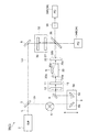
図1は、本実施形態に係る全反射分光計測装置の光学系を示す図である。同図に示すように、全反射分光計測装置1の光学系1Aは、フェムト秒レーザを光源としてテラヘルツ波Tを発生させるテラヘルツ波発生部10と、テラヘルツ波Tを全反射面20bで全反射させて出射させる内部全反射プリズム20と、内部全反射プリズム20から出射したテラヘルツ波Tを検出するテラヘルツ波検出素子(検出部)30とを含んでいる。
FIG. 1 is a diagram showing an optical system of a total reflection spectroscopic measurement apparatus according to this embodiment. As shown in the figure, the
より具体的には、全反射分光計測装置1の光学系1Aは、出射光Lとしてフェムト秒レーザを出射する光源2と、光源2からの出射光Lをプローブ光Laとポンプ光Lbとに分岐するビームスプリッタ3と、ポンプ光Lbを周期的に変調する光変調器5と、ポンプ光Lbをプローブ光Laに対して時間的に遅延させる遅延ステージ6と、ポンプ光Lbの入射によってテラヘルツ波を発生させるテラヘルツ波発生部10と、テラヘルツ波Tの入射面20a、全反射面20b及び出射面20cを有する内部全反射プリズム20と、テラヘルツ波Tを検出するテラヘルツ波検出素子30と、プローブ光Laの偏光を調整する偏光調整部32と、プローブ光Laを検出する光検出器34とを含んで構成されている。
More specifically, the
光源2から出射されるフェムト秒レーザは、例えば波長800nm、パルス幅100fs、繰り返し周波数100MHz、平均出力500mWとなっている。光変調器5は、例えば光チョッパであり、ポンプ光Lbを変調周波数f2で時間的に変調する。変調周波数f2は、例えば1kHz〜200kHzである。遅延ステージ6は、例えばビームスプリッタ3で分岐したポンプ光Lbの光軸方向に往復動可能なステージ6aと、ポンプ光Lbを折り返す一対のミラー6b,6cとを有している。遅延ステージ6を経たポンプ光Lbは、ミラー8によってテラヘルツ波発生部10に導光される。
The femtosecond laser emitted from the
テラヘルツ波発生部10は、テラヘルツ波発生素子11と波長板13とを含んでいる。テラヘルツ波発生素子11は、例えばZeTeなどの非線形光学結晶、GaAsを用いた光スイッチなどのアンテナ素子、InAsなどの半導体、超伝導体などによって構成されている。これらの素子から発生するテラヘルツ波Tのパルスは、一般的には数ピコ秒程度である。テラヘルツ波発生素子11として非線形光学結晶を用いた場合、テラヘルツ波発生素子11にポンプ光Lbが入射すると、非線形光学効果によってテラヘルツ波Tに変換される。
The terahertz
ミラー8によってテラヘルツ波発生部10に導光されたポンプ光Lbは、波長板13によってその偏光が調整され、テラヘルツ波発生素子11に入射される。テラヘルツ波発生素子11から出射されるテラヘルツ波Tは、内部全反射プリズム20の全反射面20bにおいてS偏光成分及びP偏光成分を含むように、波長板13及びテラヘルツ波発生素子11によって調整されている。テラヘルツ波発生素子11としてZeTeの(111)面を切り出した非線形光学結晶を用いた場合、波長板13によるポンプ光Lbの偏光調整とZeTeの(111)面の結晶軸の調整とによって、S偏光成分及びP偏光成分を含むテラヘルツ波Tを得ることができる。例えば、斜め22.5°の直線偏光とすることによって、テラヘルツ波Tは、光軸に対して全反射面20bを基準に斜め45°の直線偏光となる。この場合、テラヘルツ波TのS偏光成分及びP偏光成分の割合を等しくすることができる。発生したテラヘルツ波Tは、内部全反射プリズム20に入射する。
The polarization of the pump light Lb guided to the terahertz
内部全反射プリズム20は、テラヘルツ波発生素子11から出力されたテラヘルツ波Tを入射面20aに入力し、その入力したテラヘルツ波Tを内部で伝播させるとともに全反射面20bで全反射させ、その全反射した後のテラヘルツ波Tを出射面20cからテラヘルツ波検出素子30へ出力する。全反射面20bには、屈折率、誘電率、吸収係数といった各種の光学定数を測定する対象となる被測定物Sが載置される。
The internal
プローブ光Laは、ミラー9を経て偏光調整部32に導光される。偏光調整部32は、偏光子36と、λ/4波長板37とによって構成されている。偏光調整部32に導光されたプローブ光Laは、偏光子36によって所定方向の直線偏光となり、さらに、λ/4波長板37によって円偏光となる。
The probe light La is guided to the
円偏光となったプローブ光Laは、無偏光ビームスプリッタ38により偏光状態を維持したまま二分される。二分されたプローブ光Laの一方は、テラヘルツ波検出素子30に導光され、他方は、第2の光検出器34Bに導光される。
The circularly polarized probe light La is bisected by the
テラヘルツ波検出素子30は、例えば光学的等方媒質であるZnTeの(111)面を切り出した電気光学結晶によって構成されている。テラヘルツ波検出素子30の一方面30aは、テラヘルツ波Tが入射する入射面となっている。一方面30aには、テラヘルツ波Tを透過し、かつプローブ光Laを反射する反射コーティングが施されている。また、テラヘルツ波検出素子30の他方面30bは、プローブ光Laが入射する入射面となっている。他方面30bには、プローブ光Laの反射を抑制する反射防止コーティングが施されている。
The terahertz
図2は、テラヘルツ波検出素子30におけるテラヘルツ波の電場ベクトルを示す図である。同図に示すように、テラヘルツ波Tの電場ベクトルETは、振幅|ET|と、方位θTとによって表される。方位θTは、ZnTeの(111)面における<−211>方向を0°とし、これを基準として<0−11>方向を正方向としている。<−211>方向に対するテラヘルツ波Tの電場の傾きが2θである場合、複屈折は−θ方向に誘起される。テラヘルツ波Tの強さに応じて誘起される複屈折の大きさは、方向によらず一定となる。
FIG. 2 is a diagram illustrating an electric field vector of the terahertz wave in the terahertz
テラヘルツ波検出素子30に入射したプローブ光Laは、入射したタイミングでのテラヘルツ波Tの電場によって変調され、偏光状態が楕円偏光などに変化する。テラヘルツ波Tをプローブした後のプローブ光Laは、テラヘルツ波検出素子30の一方面30aで反射して無偏光ビームスプリッタ38に再び入射する。二分されたプローブ光Laの一方は、回転検光子39に入射し、他方は戻り光となる。
The probe light La incident on the terahertz
回転検光子39は、モータなどにより、検光子が面内で回転する素子である。プローブ光Laが検光子に入射すると、特定の直線偏光のみが出力される。したがって、検光子が回転する場合、プローブ光Laが変調される。回転検光子39で変調されたプローブ光Laは、第1の光検出器34Aに入射する。戻り光は、λ/4波長板37によって直線偏光に近い楕円偏光となり、大部分が偏光子36でカットされる。
The
第1の光検出器34A及び第2の光検出器34Bは、例えばフォトダイオードである。第1の光検出器34Aは、テラヘルツ波Tをプローブした後のプローブ光Laを検出する光検出器であり、回転検光子39によって変調されたプローブ光Laを検出する。第2の光検出器34Bは、パワー変動のモニタリングに用いられる光検出器であり、テラヘルツ波検出素子30に向かわずに無偏光ビームスプリッタ38を透過したプローブ光Laを検出する。
The
図3は、上述した全反射分光計測装置1の光学系1Aに接続される解析装置1Bの構成例を示すブロック図である。本実施形態では、解析装置1Bによって、電場ベクトル計測部及び解析部が構成されている。同図に示すように、解析装置1Bは、差動検出器41と、周波数演算器42と、ロックイン検出器43と、電場ベクトル検出部44と、光学定数解析部45とを備えている。
FIG. 3 is a block diagram illustrating a configuration example of the
差動検出器41は、第1の光検出器34Aからの検出信号と第2の光検出器34Bからの検出信号との差分を検出する部分である。差動検出器41は、第1の光検出器34Aからの検出信号と第2の光検出器34Bからの検出信号との差分に基づく検出信号をロックイン検出器43に出力する。差動検出を行うことにより、プローブ光Laにおけるパワー変動成分が除去される。このとき、第1の光検出器34A及び第2の光検出器34Bは、テラヘルツ波Tが入射しない状態で、かつ回転検光子39を配置していないときの差動検出器41の検出信号の強度がゼロとなるように感度調整されていることが好ましい。
The
周波数演算器42は、回転検光子39の回転周波数と、ポンプ光Lbの変調周波数とに基づく周波数を生成し、ロックイン検出器43に参照信号を出力する。より具体的には、周波数演算器42は、回転検光子39の回転周波数をf1とし、ポンプ光Lbの変調周波数をf2とした場合に、f2±2f1となる周波数を生成する。
The
ロックイン検出器43は、第1の光検出器34Aからの検出信号(ここでは差動検出器41からの検出信号)をロックイン検出する部分である。本実施形態のロックイン検出器43は、2位相ロックイン検出器であり、参照信号の周波数に同期して変化する検出信号の振幅と位相とを同時に検出する。ロックイン検出器43は、参照信号の周波数をf2±2f1として、差動検出器41から出力される検出信号のロックイン検出を行う。ロックイン検出器43からの検出信号は、電場ベクトル検出部44に出力される。回転周波数f1は、例えば20Hz〜100Hzである。
The lock-in
電場ベクトル検出部44は、ロックイン検出器43からの検出信号に基づいて、テラヘルツ波Tの電場ベクトルを検出する部分である。電場ベクトル検出部44は、物理的には、CPU、メモリ、通信インタフェイス等を備えたコンピュータシステムによって構成されている。
The electric field
ロックイン検出器43からの検出信号に含まれる振幅AL及び位相φLと、テラヘルツ波Tの電場ベクトルの振幅|ET|及び方位θTとの間には、下記の関係が成り立つ。下記式におけるACは、テラヘルツ波検出素子30として用いる電気光学結晶の非線形光学定数及び厚さ、プローブ光Laの波長などに基づいて決定される定数である。下記式により、ロックイン検出器43からの検出結果に基づいて、テラヘルツ波Tの電場ベクトルを一意に決定できる。
![]()
![]()
![]()
![]()
なお、テラヘルツ波Tの電場ベクトルの振幅が十分に小さい場合には、下記式が成立する。この場合には、ロックイン検出器43の検出信号に含まれる振幅ALを、そのままテラヘルツ波Tの電場ベクトルの振幅|ET|としてもよい。
![]()
![]()
また、2位相ロックイン検出器は、参照信号の位相に従ってALcosφLとALsinφLとをそれぞれ出力することができる。テラヘルツ波Tの電場ベクトルの振幅が十分に小さい場合、これらの出力とテラヘルツ波Tの電場ベクトルにおける互いに直交する2つの軸方向の成分との間には、下記式が成立する。したがって、ロックイン検出器43から出力される2つの出力に基づいて、テラヘルツ波Tの電場ベクトルにおける互いに直交する2つの軸方向の成分に比例する値ETx,ETyが得られることとなる。本実施形態では、テラヘルツ波Tの電場ベクトルにおける互いに直交する2つの軸方向の成分を、内部全反射プリズムの全反射面に対するS偏光成分及びP偏光成分に一致させている。これにより、電場ベクトルのS偏光成分及びP偏光成分が得られる。
![]()
![]()
![]()
![]()
光学定数解析部45は、電場ベクトル検出部44によって計測された電場ベクトルに基づいて、被測定物の光学定数に関する情報を取得する部分である。光学定数解析部45は、物理的には、CPU、メモリ、通信インタフェイス等を備えたコンピュータシステムによって構成されている。光学定数解析部45と電場ベクトル検出部44とは、同一のコンピュータシステムによって構成されてもよい。例えば、光学定数解析部45は、計測された電場ベクトルのS偏光成分及びP偏光成分のデータをメモリ等に保存しておき、必要に応じて呼び出すことができる。
The optical
本実施形態の光学定数解析部45では、全反射面20bに被測定物Sが配置されていない状態と配置されている状態とにおける、S偏光成分の反射率の比RSとP偏光成分の反射率の比RPとの比ρを利用して被測定物Sの光学定数に関する情報を取得する。この場合に、比ρは、以下の式で示される。
![]()
![]()
ここで、全反射面20bに被測定物Sが配置されていないときに計測された電場ベクトルのS偏光成分とP偏光成分とをそれぞれES0とEP0とし、全反射面20bに被測定物Sが配置されているときに計測された電場ベクトルのS偏光成分とP偏光成分とをそれぞれESとEPとすると、ρは以下のように決定される。
![]()
![]()
![]()
![]()
すなわち、ρは、全反射面20bに被測定物Sが配置されていないときに計測された電場ベクトルのS偏光成分ES0とP偏光成分EP0との比と、全反射面20bに被測定物Sが配置されているときに計測された電場ベクトルのP偏光成分EPとS偏光成分ESとの比とによって表すことができる。光学定数解析部45では、S偏光成分ES0、P偏光成分EP0、P偏光成分EP及びS偏光成分ESから求められるρを利用して、屈折率、誘電率、吸収係数といった光学定数に関する情報を取得する。
That is, ρ is the ratio of the S-polarized component E S0 and the P-polarized component E P0 of the electric field vector measured when the measured object S is not disposed on the
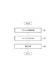
図4は、本実施形態における全反射分光計測方法を示すフローチャートである。全反射分光計測方法は、上述の全反射分光計測装置1を用いて実行され得る。
FIG. 4 is a flowchart showing the total reflection spectroscopic measurement method in the present embodiment. The total reflection spectroscopic measurement method can be executed using the total reflection
図4に示されるように、全反射分光計測方法は、リファレンス計測工程S1、サンプル計測工程S2及び解析工程S3を有している。リファレンス計測工程S1では、全反射面20bに被測定物Sが配置されていない状態で、内部全反射プリズム20から出射したテラヘルツ波Tの電場ベクトルを計測し、S偏光成分ES0とP偏光成分EP0とを取得する。また、サンプル計測工程S2では、全反射面20bに被測定物Sが配置されている状態で、内部全反射プリズム20から出射したテラヘルツ波Tの電場ベクトルを計測し、S偏光成分ESとP偏光成分EPとを取得する。リファレンス計測工程S1とサンプル計測工程S2とは、同様の環境条件の下で実施される。
As shown in FIG. 4, the total reflection spectroscopic measurement method includes a reference measurement step S1, a sample measurement step S2, and an analysis step S3. In the reference measurement step S1, the electric field vector of the terahertz wave T emitted from the internal
図4のフローチャートでは、リファレンス計測工程S1をサンプル計測工程S2よりも先に行っているが、この順番は反対でもよい。また、サンプル計測工程S2を行うたびに、リファレンス計測工程S1が行われる必要はなく、一度計測したS偏光成分ES0及びP偏光成分EP0をメモリから呼び出して利用してもよい。 In the flowchart of FIG. 4, the reference measurement step S1 is performed prior to the sample measurement step S2, but this order may be reversed. Further, each time the sample measurement step S2 is performed, the reference measurement step S1 does not need to be performed, and the S-polarized component E S0 and the P-polarized component E P0 measured once may be called from the memory and used.
図5は、リファレンス計測工程S1及びサンプル計測工程S2に共通する電場ベクトルの計測方法を示すフローチャートである。図5に示すように、この電場ベクトルの計測方法では、まず、光源2によって超短パルス光である出射光Lが出射される(ステップS11:レーザ出射ステップ)。光源2から出射した出射光Lは、ビームスプリッタ3によってプローブ光Laとポンプ光Lbとに二分される。ポンプ光Lbは、光変調器5によって時間的に変調され(ステップS12:ポンプ光変調ステップ)、遅延ステージ6を通過することによって時間的に遅延させられる(ステップS13:遅延ステップ)。
FIG. 5 is a flowchart showing an electric field vector measurement method common to the reference measurement step S1 and the sample measurement step S2. As shown in FIG. 5, in this electric field vector measurement method, first, the
遅延ステージ6を通過したポンプ光Lbは、テラヘルツ波発生部に入射し、テラヘルツ波Tを発生させる(ステップS14:テラヘルツ波発生ステップ)。テラヘルツ波発生素子11で発生したテラヘルツ波Tは、内部全反射プリズム20に入射し、全反射面20bで反射されて、テラヘルツ波検出素子30に入射する(ステップS15:テラヘルツ波検出ステップ)。
The pump light Lb that has passed through the delay stage 6 is incident on the terahertz wave generation unit and generates the terahertz wave T (step S14: terahertz wave generation step). The terahertz wave T generated by the terahertz
一方、プローブ光Laは、偏光調整部32に導光され、偏光状態が円偏光となる(ステップS16:偏光状態調整ステップ)。偏光状態が円偏光となったプローブ光Laは、テラヘルツ波検出素子30に入射し、テラヘルツ波Tのプローブがなされる(ステップS17:テラヘルツ波プローブステップ)。このとき、テラヘルツ波Tの偏光状態は、テラヘルツ波Tの電場ベクトルによって変化する。
On the other hand, the probe light La is guided to the
プローブ後のプローブ光Laは、回転検光子39によって変調され(ステップS18:プローブ光変調ステップ)、第1の光検出器34Aによって検出される(ステップS19:プローブ光検出ステップ)。また、プローブに用いられなかったプローブ光Laは、第2の光検出器34Bによって検出される。
The probe light La after the probe is modulated by the rotation analyzer 39 (step S18: probe light modulation step) and detected by the
次に、第1の光検出器34A及び第2の光検出器34Bからの検出信号がそれぞれ差動検出器41に出力され、差動検出が行われる。また、周波数演算器42によって、回転検光子39の回転周波数と、ポンプ光Lbの変調周波数とに基づく周波数が生成され、ロックイン検出器43に出力される(ステップS20:差動検出ステップ及び周波数演算ステップ)。
Next, detection signals from the
差動検出器41からの検出信号がロックイン検出器43に出力されると、周波数演算器42によって生成された周波数を参照信号としてロックイン検出が行われる(ステップS21:ロックイン検出ステップ)。ロックイン検出器43からの検出信号は、電場ベクトル検出部44に出力され、ロックイン検出器43からの検出信号に含まれる振幅及び位相に基づいて、テラヘルツ波Tの電場ベクトルの振幅及び方向が検出される(ステップS22:電場ベクトル検出ステップ)。
When the detection signal from the
再び図4に戻り、解析工程S3では、リファレンス計測工程S1で取得された電場ベクトルのS偏光成分ES0とP偏光成分EP0との比と、サンプル計測工程S2で計測された電場ベクトルのP偏光成分EPとS偏光成分ESとの比とに基づいてρを求め、光学定数に関する情報を取得する。この工程は、光学定数解析部45によって実行される。
Returning to FIG. 4 again, in the analysis step S3, the ratio of the S-polarized component E S0 and the P-polarized component E P0 of the electric field vector obtained in the reference measurement step S1 and the electric field vector P measured in the sample measurement step S2. Ρ is obtained based on the ratio of the polarization component E P and the S polarization component E S, and information on the optical constant is obtained. This step is executed by the optical
次に、本実施形態の作用効果について説明する。図6は、テラヘルツ波発生部10によって発生したテラヘルツ波のP偏光成分とS偏光成分との関係を模式的に示す図である。図6の(a)は、あるタイミングで発生したテラヘルツ波の電場ベクトルE1を示している。また、図6の(b)は、図6の(a)とは異なるタイミングで発生したテラヘルツ波の電場ベクトルE2を示している。図示例では、図6の(a)の場合のテラヘルツ波に比べて、(b)の場合のテラヘルツ波のパワーが小さくなっている。このように、異なる時間にテラヘルツ波発生部10で発生した2つのテラヘルツ波のパワーは、変動している場合がある。そのため、従来の技術では、リファレンスの信号と被測定物を測定した信号とで変化が計測されたとしても、被測定物の有無による変化であるのか、光源のパワーの変動による変化であるのかの区別が困難となることが考えられる。
Next, the effect of this embodiment is demonstrated. FIG. 6 is a diagram schematically illustrating the relationship between the P-polarized component and the S-polarized component of the terahertz wave generated by the terahertz
本実施形態の全反射分光計測装置1では、リファレンス計測工程S1で計測された電場ベクトルのS偏光成分ES0とP偏光成分EP0との比ES0/EP0と、サンプル計測工程S2で計測された電場ベクトルのP偏光成分EPとS偏光成分ESとの比EP/ESとに基づいて、光学定数を導出している。ここで、テラヘルツ波発生部10では、入力されるフェムト秒レーザであるポンプ光Lbの偏光調整が行われている。これにより、図6に示されるように、時間によって異なるパワーのテラヘルツ波が発生した場合であっても、ある時間の電場ベクトルE1のS偏光成分EST1とP偏光成分EPT1との比率と、別の時間の電場ベクトルE2のS偏光成分EST2とP偏光成分EPT2との比率とは同一となっている。そのため、リファレンス工程S1で計測される電場ベクトルのS偏光成分ES0とP偏光成分EP0との比ES0/EP0は、フェムト秒レーザのパワー変動の影響を受けない。したがって、リファレンス計測工程S1とサンプル計測工程S2との間の時間経過に伴って、フェムト秒レーザのパワーが変動した場合であっても、フェムト秒レーザのパワー変動の影響を受けずに光学定数を導出することができる。
In the total reflection
また、内部全反射プリズム20に入射されるテラヘルツ波Tが、S偏光成分及びP偏光成分の割合が等しい直線偏光であるため、S偏光成分とP偏光成分とを偏りなく照射することができ、安定した計測を行うことができる。なお、内部全反射プリズム20に入射されるテラヘルツ波Tは、S偏光成分及びP偏光成分の割合が等しい円偏光であってもよい。
In addition, since the terahertz wave T incident on the internal
以上、本発明の実施の形態について図面を参照して詳述したが、具体的な構成はこの実施形態に限られるものではない。内部全反射プリズム20の出射面20cから出射したテラヘルツ波の電場ベクトルの計測は、上記計測方法以外の他の計測方法によって実行され得る。例えば、テラヘルツ波検出素子30として光学的等方媒質であるZnTeの(111)面を切り出した電気光学結晶を例示したが、電気光学結晶はGaPなどの他の光学的等方媒質の(111)面を切り出した結晶であってもよい。
As mentioned above, although embodiment of this invention was explained in full detail with reference to drawings, a specific structure is not restricted to this embodiment. The measurement of the electric field vector of the terahertz wave emitted from the
また、内部全反射プリズムに入射されるテラヘルツ波は、S偏光成分とP偏光成分との割合が異なる直線偏光又は楕円偏光であってもよい。この構成によれば、S偏光成分とP偏光成分との割合が等しくなるような厳密なアライメントをする必要がない。 Further, the terahertz wave incident on the internal total reflection prism may be linearly polarized light or elliptically polarized light in which the ratio of the S polarization component and the P polarization component is different. According to this configuration, it is not necessary to perform strict alignment such that the ratio of the S-polarized component and the P-polarized component is equal.
1…全反射分光計測装置、1A…光学系、1B…解析装置、10…テラヘルツ波発生部、20…内部全反射プリズム、20a…入射面、20b…全反射面、20c…出射面、30…テラヘルツ波検出素子(検出部)、44…電場ベクトル検出部、45…光学定数解析部(解析部)、T…テラヘルツ波。
DESCRIPTION OF
Claims (6)
前記テラヘルツ波の入射面及び出射面を有し、前記入射面から入射した前記テラヘルツ波を内部で伝播させるとともに全反射面で全反射させて前記出射面から出射させる内部全反射プリズムと、
前記内部全反射プリズムの前記出射面から出射した前記テラヘルツ波を検出する検出部と、
前記検出部によって検出された前記テラへルツ波の電場ベクトルを計測する電場ベクトル計測部と、
電場ベクトル計測部によって計測された電場ベクトルに基づいて、前記内部全反射プリズムの前記全反射面に配置された被測定物の光学定数に関する情報を取得する解析部と、を備え、
前記テラヘルツ波発生部によって発生される前記テラヘルツ波は、前記全反射面に対するS偏光成分及びP偏光成分を互いの比率が一定となるように含み、
前記解析部は、前記全反射面に前記被測定物が配置されていないときに計測された前記電場ベクトルのS偏光成分とP偏光成分との比と、前記全反射面に前記被測定物が配置されているときに計測された前記電場ベクトルのP偏光成分とS偏光成分との比とに基づいて前記光学定数に関する情報を取得する、全反射分光計測装置。 A terahertz wave generator for generating terahertz waves;
An internal total reflection prism having an incidence surface and an emission surface of the terahertz wave, propagating the terahertz wave incident from the incidence surface inside and totally reflecting the total reflection surface to be emitted from the emission surface;
A detection unit for detecting the terahertz wave emitted from the emission surface of the internal total reflection prism;
An electric field vector measurement unit that measures an electric field vector of the terahertz wave detected by the detection unit;
Based on the electric field vector measured by the electric field vector measuring unit, an analysis unit that acquires information on the optical constant of the object to be measured arranged on the total reflection surface of the internal total reflection prism, and
The terahertz wave generated by the terahertz wave generation unit includes an S-polarized component and a P-polarized component with respect to the total reflection surface so that the ratio between them is constant,
The analysis unit includes a ratio of an S-polarized component and a P-polarized component of the electric field vector measured when the device to be measured is not disposed on the total reflection surface, and the device to be measured on the total reflection surface. A total reflection spectroscopic measurement apparatus that acquires information on the optical constant based on a ratio of a P-polarized component and an S-polarized component of the electric field vector measured when the electric field vector is arranged.
前記全反射面に前記被測定物が配置されていないときに、前記全反射面に対するS偏光成分及びP偏光成分を互いの比率が一定となるように含む前記テラヘルツ波を前記内部全反射プリズムに入射し、内部全反射プリズムから出射した前記テラヘルツ波の電場ベクトルを計測する工程と、
前記全反射面に前記被測定物が配置されているときに、前記全反射面に対するS偏光成分及びP偏光成分を前記比率で含む前記テラヘルツ波を前記内部全反射プリズムに入射し、内部全反射プリズムから出射した前記テラヘルツ波の電場ベクトルを計測する工程と、
前記被測定物が配置されていないときに計測された前記電場ベクトルのS偏光成分とP偏光成分との比と、前記被測定物が配置されているときに計測された前記電場ベクトルのP偏光成分とS偏光成分との比とに基づいて前記光学定数に関する情報を取得する工程と、を含む、全反射分光計測方法。 Total reflection spectroscopy that acquires information on the optical constant of the object to be measured based on the terahertz wave totally reflected by the total reflection surface through the interior of the total internal reflection prism having the total reflection surface on which the object to be measured is disposed Measuring method,
When the object to be measured is not disposed on the total reflection surface, the terahertz wave including the S-polarized component and the P-polarized component with respect to the total reflection surface so as to have a constant ratio to the total internal reflection prism. Measuring the electric field vector of the terahertz wave incident and emitted from the internal total reflection prism;
When the object to be measured is disposed on the total reflection surface, the terahertz wave including the S-polarized component and the P-polarized component with respect to the total reflection surface in the ratio is incident on the internal total reflection prism, and the total internal reflection is performed. Measuring the electric field vector of the terahertz wave emitted from the prism;
The ratio of the S-polarized component and the P-polarized component of the electric field vector measured when the object to be measured is not arranged, and the P-polarized light of the electric field vector measured when the object to be measured is arranged. Obtaining information on the optical constant based on the ratio of the component and the S-polarized component.
Priority Applications (2)
| Application Number | Priority Date | Filing Date | Title |
|---|---|---|---|
| JP2016101709A JP6646519B2 (en) | 2016-05-20 | 2016-05-20 | Total reflection spectrometer and total reflection spectrometer |
| US15/597,329 US10048129B2 (en) | 2016-05-20 | 2017-05-17 | Total reflection spectroscopic measurement device and total reflection spectroscopic measurement method |
Applications Claiming Priority (1)
| Application Number | Priority Date | Filing Date | Title |
|---|---|---|---|
| JP2016101709A JP6646519B2 (en) | 2016-05-20 | 2016-05-20 | Total reflection spectrometer and total reflection spectrometer |
Publications (2)
| Publication Number | Publication Date |
|---|---|
| JP2017207446A true JP2017207446A (en) | 2017-11-24 |
| JP6646519B2 JP6646519B2 (en) | 2020-02-14 |
Family
ID=60330037
Family Applications (1)
| Application Number | Title | Priority Date | Filing Date |
|---|---|---|---|
| JP2016101709A Active JP6646519B2 (en) | 2016-05-20 | 2016-05-20 | Total reflection spectrometer and total reflection spectrometer |
Country Status (2)
| Country | Link |
|---|---|
| US (1) | US10048129B2 (en) |
| JP (1) | JP6646519B2 (en) |
Families Citing this family (7)
| Publication number | Priority date | Publication date | Assignee | Title |
|---|---|---|---|---|
| JP2017078599A (en) * | 2015-10-19 | 2017-04-27 | フェムトディプロイメンツ株式会社 | Terahertz time-resolved spectroscopy apparatus |
| US10197793B2 (en) * | 2016-05-12 | 2019-02-05 | The Chinese University Of Hong Kong | Light modulator using total internal reflection at an interface with a tunable conductive layer |
| JP7014623B2 (en) * | 2018-01-29 | 2022-02-01 | 浜松ホトニクス株式会社 | Terahertz wave spectroscopic measuring device |
| CN109406445A (en) * | 2018-09-29 | 2019-03-01 | 深圳市华讯方舟太赫兹科技有限公司 | Liquid identification method, feature extracting method, Liquid identification device and storage device |
| JPWO2021038743A1 (en) * | 2019-08-28 | 2021-03-04 | ||
| JP2022052306A (en) * | 2020-09-23 | 2022-04-04 | 浜松ホトニクス株式会社 | Terahertz wave total reflection attenuation spectroscopic method, terahertz wave total reflection attenuation spectroscopic device, and pressure application device |
| CN115128823B (en) * | 2022-06-17 | 2024-03-15 | 上海理工大学 | Terahertz polarization state conversion method based on orthogonal parallel plates |
Citations (3)
| Publication number | Priority date | Publication date | Assignee | Title |
|---|---|---|---|---|
| JP2003014620A (en) * | 2001-06-27 | 2003-01-15 | Matsushita Electric Ind Co Ltd | Polarization analysis apparatus and method |
| WO2009133853A1 (en) * | 2008-04-30 | 2009-11-05 | 浜松ホトニクス株式会社 | Total reflection terahertz wave measurement device |
| WO2010106589A1 (en) * | 2009-03-18 | 2010-09-23 | 株式会社村田製作所 | Optical measuring instrument and optical measurement method |
Family Cites Families (3)
| Publication number | Priority date | Publication date | Assignee | Title |
|---|---|---|---|---|
| JP4490777B2 (en) * | 2004-09-27 | 2010-06-30 | 株式会社堀場製作所 | Method for identifying film forming conditions |
| JP4481967B2 (en) * | 2005-09-05 | 2010-06-16 | キヤノン株式会社 | Sensor device |
| JP6096725B2 (en) * | 2014-09-09 | 2017-03-15 | アイシン精機株式会社 | Film thickness measuring apparatus and film thickness measuring method |
-
2016
- 2016-05-20 JP JP2016101709A patent/JP6646519B2/en active Active
-
2017
- 2017-05-17 US US15/597,329 patent/US10048129B2/en active Active
Patent Citations (5)
| Publication number | Priority date | Publication date | Assignee | Title |
|---|---|---|---|---|
| JP2003014620A (en) * | 2001-06-27 | 2003-01-15 | Matsushita Electric Ind Co Ltd | Polarization analysis apparatus and method |
| US20030016358A1 (en) * | 2001-06-27 | 2003-01-23 | Matsushita Electric Industrial Co., Ltd. | Polarization analyzing apparatus and method for polarization analysis |
| WO2009133853A1 (en) * | 2008-04-30 | 2009-11-05 | 浜松ホトニクス株式会社 | Total reflection terahertz wave measurement device |
| US20110249253A1 (en) * | 2008-04-30 | 2011-10-13 | Hamamatsu Photonics K.K. | Total reflection terahertz wave measurement device |
| WO2010106589A1 (en) * | 2009-03-18 | 2010-09-23 | 株式会社村田製作所 | Optical measuring instrument and optical measurement method |
Also Published As
| Publication number | Publication date |
|---|---|
| JP6646519B2 (en) | 2020-02-14 |
| US20170336259A1 (en) | 2017-11-23 |
| US10048129B2 (en) | 2018-08-14 |
Similar Documents
| Publication | Publication Date | Title |
|---|---|---|
| JP6646519B2 (en) | Total reflection spectrometer and total reflection spectrometer | |
| JP6397318B2 (en) | Electric field vector detection method and electric field vector detection device | |
| US20120326037A1 (en) | Coating film inspection apparatus and inspection method | |
| WO2015038561A1 (en) | Cavity-enhanced frequency comb spectroscopy system employing a prism cavity | |
| CN107655599B (en) | Method for measuring micro stress of optical element | |
| JP6682351B2 (en) | Optical analysis apparatus and optical analysis method | |
| US10119903B2 (en) | Interferometric ellipsometry and method using conical refraction | |
| JPH05264609A (en) | Method and system for measuring high frequency electric signal through electrooptic effect | |
| JP3533651B1 (en) | Time-resolved nonlinear susceptibility measurement system | |
| JP6652542B2 (en) | Optical analysis device and optical analysis method | |
| RU2005130289A (en) | ELLIPSOMETER | |
| JP7041015B2 (en) | Calibration method of electric field vector measurement | |
| JP7041022B2 (en) | Optical analysis module and optical analysis device | |
| JP5550521B2 (en) | Total reflection spectrometer | |
| TWI479141B (en) | Ellipsometry and polarization modulation ellipsometry method for the | |
| JP5566826B2 (en) | Data analysis method in total reflection spectroscopy measurement | |
| US9778019B2 (en) | Differential polarization interferometer | |
| Tiwari et al. | Laser frequency stabilization using a balanced bi-polarimeter | |
| CN109115690B (en) | Terahertz time domain ellipsometer sensitive to real-time polarization and optical constant measurement method | |
| KR102380250B1 (en) | Apparatus for measuring reflectivity and incident light | |
| JPH05302810A (en) | Heterodyne two wave lengths displacement interference meter | |
| Settembrini et al. | Third order nonlinear correlation of the electromagnetic vacuum at near-infrared frequencies | |
| Jin et al. | Effect of multiple reflections on accuracy of electro-optic coefficient measurements | |
| CN109115690A (en) | Real-time polarization sensitive terahertz time-domain ellipsometer and optical constant measuring method | |
| Ibrahim et al. | Ultra high dynamic range electro optic sampling for terahertz detection using fiber based spectral domain interferometry |
Legal Events
| Date | Code | Title | Description |
|---|---|---|---|
| A621 | Written request for application examination |
Free format text: JAPANESE INTERMEDIATE CODE: A621 Effective date: 20190124 |
|
| A977 | Report on retrieval |
Free format text: JAPANESE INTERMEDIATE CODE: A971007 Effective date: 20191219 |
|
| TRDD | Decision of grant or rejection written | ||
| A01 | Written decision to grant a patent or to grant a registration (utility model) |
Free format text: JAPANESE INTERMEDIATE CODE: A01 Effective date: 20200107 |
|
| A61 | First payment of annual fees (during grant procedure) |
Free format text: JAPANESE INTERMEDIATE CODE: A61 Effective date: 20200110 |
|
| R150 | Certificate of patent or registration of utility model |
Ref document number: 6646519 Country of ref document: JP Free format text: JAPANESE INTERMEDIATE CODE: R150 |
|
| R250 | Receipt of annual fees |
Free format text: JAPANESE INTERMEDIATE CODE: R250 |