JP2017207182A - Electric actuator - Google Patents
Electric actuator Download PDFInfo
- Publication number
- JP2017207182A JP2017207182A JP2016101546A JP2016101546A JP2017207182A JP 2017207182 A JP2017207182 A JP 2017207182A JP 2016101546 A JP2016101546 A JP 2016101546A JP 2016101546 A JP2016101546 A JP 2016101546A JP 2017207182 A JP2017207182 A JP 2017207182A
- Authority
- JP
- Japan
- Prior art keywords
- ball screw
- electric actuator
- guide member
- casing
- screw shaft
- Prior art date
- Legal status (The legal status is an assumption and is not a legal conclusion. Google has not performed a legal analysis and makes no representation as to the accuracy of the status listed.)
- Pending
Links
- 230000033001 locomotion Effects 0.000 claims abstract description 25
- 238000005096 rolling process Methods 0.000 claims abstract description 23
- 238000006243 chemical reaction Methods 0.000 claims abstract description 18
- 230000007246 mechanism Effects 0.000 claims abstract description 18
- 230000002093 peripheral effect Effects 0.000 claims description 25
- 238000004519 manufacturing process Methods 0.000 abstract description 8
- 238000001514 detection method Methods 0.000 description 15
- 230000002265 prevention Effects 0.000 description 8
- 239000000463 material Substances 0.000 description 7
- 238000000034 method Methods 0.000 description 6
- 230000006835 compression Effects 0.000 description 5
- 238000007906 compression Methods 0.000 description 5
- 238000010586 diagram Methods 0.000 description 3
- 239000007787 solid Substances 0.000 description 3
- 230000000694 effects Effects 0.000 description 2
- 238000010438 heat treatment Methods 0.000 description 2
- 239000011347 resin Substances 0.000 description 2
- 229920005989 resin Polymers 0.000 description 2
- 238000005496 tempering Methods 0.000 description 2
- 229910001209 Low-carbon steel Inorganic materials 0.000 description 1
- 229910000861 Mg alloy Inorganic materials 0.000 description 1
- 229910001297 Zn alloy Inorganic materials 0.000 description 1
- XAGFODPZIPBFFR-UHFFFAOYSA-N aluminium Chemical compound [Al] XAGFODPZIPBFFR-UHFFFAOYSA-N 0.000 description 1
- 229910052782 aluminium Inorganic materials 0.000 description 1
- 230000004323 axial length Effects 0.000 description 1
- 230000005540 biological transmission Effects 0.000 description 1
- 230000008859 change Effects 0.000 description 1
- 239000003638 chemical reducing agent Substances 0.000 description 1
- 230000018109 developmental process Effects 0.000 description 1
- 239000000446 fuel Substances 0.000 description 1
- 238000009434 installation Methods 0.000 description 1
- 238000009413 insulation Methods 0.000 description 1
- 230000010354 integration Effects 0.000 description 1
- 238000012986 modification Methods 0.000 description 1
- 230000004048 modification Effects 0.000 description 1
- 230000000149 penetrating effect Effects 0.000 description 1
- 238000010791 quenching Methods 0.000 description 1
- 230000000171 quenching effect Effects 0.000 description 1
- 230000009467 reduction Effects 0.000 description 1
- 238000007789 sealing Methods 0.000 description 1
- 238000004804 winding Methods 0.000 description 1
Images


Classifications
-
- F—MECHANICAL ENGINEERING; LIGHTING; HEATING; WEAPONS; BLASTING
- F16—ENGINEERING ELEMENTS AND UNITS; GENERAL MEASURES FOR PRODUCING AND MAINTAINING EFFECTIVE FUNCTIONING OF MACHINES OR INSTALLATIONS; THERMAL INSULATION IN GENERAL
- F16H—GEARING
- F16H25/00—Gearings comprising primarily only cams, cam-followers and screw-and-nut mechanisms
- F16H25/18—Gearings comprising primarily only cams, cam-followers and screw-and-nut mechanisms for conveying or interconverting oscillating or reciprocating motions
- F16H25/20—Screw mechanisms
- F16H25/22—Screw mechanisms with balls, rollers, or similar members between the co-operating parts; Elements essential to the use of such members
- F16H25/2204—Screw mechanisms with balls, rollers, or similar members between the co-operating parts; Elements essential to the use of such members with balls
-
- F—MECHANICAL ENGINEERING; LIGHTING; HEATING; WEAPONS; BLASTING
- F16—ENGINEERING ELEMENTS AND UNITS; GENERAL MEASURES FOR PRODUCING AND MAINTAINING EFFECTIVE FUNCTIONING OF MACHINES OR INSTALLATIONS; THERMAL INSULATION IN GENERAL
- F16H—GEARING
- F16H25/00—Gearings comprising primarily only cams, cam-followers and screw-and-nut mechanisms
- F16H25/18—Gearings comprising primarily only cams, cam-followers and screw-and-nut mechanisms for conveying or interconverting oscillating or reciprocating motions
- F16H25/20—Screw mechanisms
-
- H—ELECTRICITY
- H02—GENERATION; CONVERSION OR DISTRIBUTION OF ELECTRIC POWER
- H02K—DYNAMO-ELECTRIC MACHINES
- H02K7/00—Arrangements for handling mechanical energy structurally associated with dynamo-electric machines, e.g. structural association with mechanical driving motors or auxiliary dynamo-electric machines
- H02K7/06—Means for converting reciprocating motion into rotary motion or vice versa
-
- F—MECHANICAL ENGINEERING; LIGHTING; HEATING; WEAPONS; BLASTING
- F16—ENGINEERING ELEMENTS AND UNITS; GENERAL MEASURES FOR PRODUCING AND MAINTAINING EFFECTIVE FUNCTIONING OF MACHINES OR INSTALLATIONS; THERMAL INSULATION IN GENERAL
- F16H—GEARING
- F16H25/00—Gearings comprising primarily only cams, cam-followers and screw-and-nut mechanisms
- F16H25/18—Gearings comprising primarily only cams, cam-followers and screw-and-nut mechanisms for conveying or interconverting oscillating or reciprocating motions
- F16H25/20—Screw mechanisms
- F16H2025/204—Axial sliding means, i.e. for rotary support and axial guiding of nut or screw shaft
-
- F—MECHANICAL ENGINEERING; LIGHTING; HEATING; WEAPONS; BLASTING
- F16—ENGINEERING ELEMENTS AND UNITS; GENERAL MEASURES FOR PRODUCING AND MAINTAINING EFFECTIVE FUNCTIONING OF MACHINES OR INSTALLATIONS; THERMAL INSULATION IN GENERAL
- F16H—GEARING
- F16H25/00—Gearings comprising primarily only cams, cam-followers and screw-and-nut mechanisms
- F16H25/18—Gearings comprising primarily only cams, cam-followers and screw-and-nut mechanisms for conveying or interconverting oscillating or reciprocating motions
- F16H25/20—Screw mechanisms
- F16H2025/2062—Arrangements for driving the actuator
- F16H2025/2075—Coaxial drive motors
Abstract
Description
本発明は、電動アクチュエータに関する。 The present invention relates to an electric actuator.
近年、車両等の省力化、低燃費化のために電動化が進み、例えば、自動車の自動変速機やブレーキ、ステアリング等の操作を電動機の力で行うシステムが開発され、市場に投入されている。このような用途に使用されるアクチュエータとして、電動機の回転運動を直線方向の運動に変換するために、ボールねじ機構を用いたものがある(特許文献1)。 In recent years, electrification has progressed to save power and reduce fuel consumption of vehicles, etc., for example, a system for operating an automatic transmission, brakes, steering, etc. of an automobile with the power of an electric motor has been developed and put on the market. . As an actuator used for such an application, there is one using a ball screw mechanism in order to convert the rotational motion of an electric motor into linear motion (Patent Document 1).
特許文献1には、ボールねじのナットと電動機のロータとを一体として、電動機のロータにボールねじのナットの機能を持たせ、ロータの一部に、ロータを支持する転がり軸受の内輪を兼用させた電動アクチュエータが提案されている。そして、この電動アクチュエータを自動車等の車両用として用いる場合、質量をできるだけ小さくすること、コストをできるだけ低減すること等の要求から、できる限り部品点数が少ない構成が望ましいとしている。また、ロータ(ボールねじのナット)と転がり軸受の内輪とを一体化することに関して、転がり軸受の内輪とボールねじのナットとは、それぞれの材料に求められる機能が共通するため、同一の材料を使用することができるとしている。
In
しかしながら、部品を共用化した多品種展開により直動アクチュエータをシリーズ化するに際し、ボールねじのナットの共用化を考慮すると、ロータとボールねじのナットの一体化によって得られる効果は少ないということが判明した。 However, it has been found that there is little effect obtained by integrating the rotor and ball screw nuts when considering the common use of ball screw nuts in the series of linear actuators due to the development of a variety of parts that share parts. did.
また、モータの回転バランスを取ると、ロータコアを支持する転がり軸受に負荷されるラジアル荷重はロータコアの自重程度であるので、転がり軸受には強度の高い材料を使用する必要がなく、安価な軟鋼で熱処理も必要がない、もしくは高温焼戻し(調質)程度でよいことが判明した。 In addition, when balancing the rotation of the motor, the radial load applied to the rolling bearing that supports the rotor core is about the weight of the rotor core.Therefore, it is not necessary to use a high-strength material for the rolling bearing. It has been found that no heat treatment is required, or that high temperature tempering (tempering) is sufficient.
さらに、電動アクチュエータのシリーズ化を追求する中で、特許文献1の電動アクチュエータは、必要なストローク量が異なる用途に対して一品一葉の専用設計となり、部品を共用化した多品種展開による直動アクチュエータのシリーズ化には問題があることが判明した。この問題に着目し、電動アクチュエータのケーシングを共用化して、異なるストローク量に対応可能なシリーズ化が望ましいことに辿りついた。
Furthermore, in the pursuit of the series of electric actuators, the electric actuator of
以上の問題に鑑み、本発明は、小型で搭載性が良く、必要なストローク量が異なる用途に対して低コストで対応可能で、シリーズ化に好適な電動アクチュエータを提供することを目的とする。 In view of the above problems, an object of the present invention is to provide an electric actuator that is small in size, has good mountability, can be used at low cost for applications having different required stroke amounts, and is suitable for series production.
本発明者らは、上記の目的を達成するため種々検討した結果、電動アクチュエータのボールねじ軸の回り止めガイド部材をストローク量に応じて付け替え可能にするという新たな着想に至った。 As a result of various studies to achieve the above object, the present inventors have come up with a new idea that the rotation guide member of the ball screw shaft of the electric actuator can be changed according to the stroke amount.
前述の目的を達成するための技術的手段として、モータ部と運動変換機構部と操作部とターミナル部を備えた電動アクチュエータであって、前記モータ部のロータコアを支持する中空回転軸が転がり軸受によって回転自在に支持され、前記運動変換機構部が前記中空回転軸に連結されると共にボールねじを備え、このボールねじのボールねじナットが前記中空回転軸の内部に配置され、前記操作部が前記運動変換機構部に連結された電動アクチュエータにおいて、前記ボールねじ軸と回り止めガイド部が凹凸嵌合され、前記ボールねじ軸が前記回り止めガイド部の軸方向幅に基づくストローク量で案内され、前記回り止めガイド部が前記電動アクチュエータのケーシングとは別体の回り止めガイド部材により形成され、前記ケーシングの前記操作部側の端部と前記回り止めガイド部材が、当該回り止めガイド部材の付け替えを可能にする連結構造を有することを特徴とする。上記の構成により、小型で搭載性が良く、必要なストローク量が異なる用途に対して低コストで対応可能で、シリーズ化に好適な電動アクチュエータを実現することができる。 As a technical means for achieving the above-mentioned object, an electric actuator including a motor unit, a motion conversion mechanism unit, an operation unit, and a terminal unit, wherein a hollow rotary shaft that supports a rotor core of the motor unit is formed by a rolling bearing. The motion conversion mechanism is connected to the hollow rotary shaft and includes a ball screw. A ball screw nut of the ball screw is disposed inside the hollow rotary shaft, and the operation unit is moved to the motion. In the electric actuator connected to the conversion mechanism portion, the ball screw shaft and the non-rotating guide portion are concavo-convexly fitted, and the ball screw shaft is guided by a stroke amount based on the axial width of the non-rotating guide portion. The stop guide portion is formed by a rotation guide member separate from the casing of the electric actuator, The rotating guide member and the end portion of the work portion side, and having a connecting structure that allows replacement of the rotating guide member. With the above configuration, it is possible to realize an electric actuator that is small in size, has good mountability, can be used at low cost for applications with different required stroke amounts, and is suitable for series production.
上記の付け替えられる回り止めガイド部材のストローク量が異なることにより、電動アクチュエータの本体(モータ部A、運動変換機構部B、ターミナル部Dやケーシング等)を共用化して、必要なストローク量が異なる用途に対して低コストで対応可能で、シリーズ化に好適な電動アクチュエータを実現することができる。 Applications that require different stroke amounts by sharing the main body of the electric actuator (motor part A, motion conversion mechanism part B, terminal part D, casing, etc.) by changing the stroke amount of the non-rotating guide member to be replaced. Therefore, an electric actuator suitable for series production can be realized.
上記のボールねじ軸と回り止めガイド部が凹凸嵌合される構成が、回り止めガイド部材の内周部に設けられた案内溝と、この案内溝に嵌め込まれる前記ボールねじ軸に設けられた係止部材であることが好ましい。これにより、簡単な構成で回り止めガイド部を形成できると共に、ストローク量の異なる回り止めガイド部材を容易に製作することができる。 The configuration in which the above-described ball screw shaft and the non-rotating guide portion are concavo-convex-fitted includes a guide groove provided in the inner peripheral portion of the anti-rotation guide member, and an engagement provided in the ball screw shaft fitted in the guide groove. A stop member is preferred. Thereby, while being able to form a rotation prevention guide part by simple structure, the rotation prevention guide member from which stroke amount differs can be manufactured easily.
上記の係止部材を、ボールねじ軸に設けられたピンと、このピンに外嵌されたガイドカラーとで構成することにより、簡単な構成で滑らかな案内が可能になる。 By configuring the locking member with a pin provided on the ball screw shaft and a guide collar fitted around the pin, smooth guidance can be achieved with a simple configuration.
上記の回り止めガイド部材とケーシングの連結構造が、少なくとも1個所の固定手段を有し、ケーシングに対する回り止めガイド部材の相対回転が防止されることにより、回り止めガイド部材に設けた案内溝の回転位相方向の精度も良好である。また、回り止めガイド部材の組込、連結作業性が容易である。 The connection structure of the anti-rotation guide member and the casing has at least one fixing means, and the rotation of the guide groove provided in the anti-rotation guide member is prevented by preventing relative rotation of the anti-rotation guide member with respect to the casing. The accuracy in the phase direction is also good. Further, the assembly and connection workability of the non-rotating guide member is easy.
上記の固定手段を、回り止めガイド部材に設けられた貫通孔と、ケーシングに設けられたキー溝と、これら貫通孔とキー溝に挿入されるピンから構成することにより、ガタつきなく、回り止めガイド部材に設けた案内溝の回転位相方向の精度も良好で、また、回り止めガイド部材の組込、連結作業性が容易である。 By forming the fixing means from a through hole provided in the non-rotating guide member, a key groove provided in the casing, and a pin inserted into the through hole and the key groove, the anti-rotation is prevented. The accuracy in the rotational phase direction of the guide groove provided in the guide member is also good, and the assembly and connection workability of the non-rotating guide member is easy.
本発明によれば、小型で搭載性が良く、必要なストローク量が異なる用途に対して低コストで対応可能で、シリーズ化に好適な電動アクチュエータを実現することができる。 According to the present invention, it is possible to realize an electric actuator that is small in size, has good mountability, can be used at low cost for applications with different required stroke amounts, and is suitable for series production.
本発明の一実施形態に係る電動アクチュエータを図1〜図13に基づいて説明する。まず、本実施形態の電動アクチュエータの全体構成を説明する。 An electric actuator according to an embodiment of the present invention will be described with reference to FIGS. First, the overall configuration of the electric actuator of this embodiment will be described.
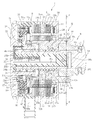
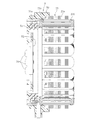
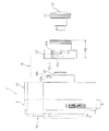
図1は、本実施形態の電動アクチュエータの組み立て状態を示す縦断面図で、図2は、図1のE−E線で矢視した縦断面図である。図1および図2に示すように、電動アクチュエータ1は、駆動力を発生させるモータ部A、モータ部Aの回転を変換して出力する運動変換機構部B、運動変換機構部Bの運動を出力する操作部C、電源供給回路やセンサ等を備えるターミナル部Dを主な構成とする。
FIG. 1 is a longitudinal sectional view showing an assembled state of the electric actuator of the present embodiment, and FIG. 2 is a longitudinal sectional view taken along the line E-E in FIG. As shown in FIGS. 1 and 2, the
モータ部Aと運動変換機構部Bはケーシング20内に収容されている。モータ部Aは、ケーシング20に固定されたステータ23と、ステータ23の径方向内側に隙間をもって対向するように配置されたロータ24とからなるラジアルギャップ型のモータ25で構成されている。ステータ23はステータコア23aに絶縁のためボビン23bを装着し、ボビン23bにコイル23cを巻回することによって構成されている。ロータ24は、ロータコア24aと、ロータコア24aの外周に取付けられた永久磁石24b(図2参照)とからなる。ロータ24は、中空回転軸としてのロータインナ26に外嵌され、取付固定されている。
The motor part A and the motion conversion mechanism part B are accommodated in the
ロータインナ26は、一端部(図1、図2の右側)外周に転がり軸受27の内側軌道面27aが形成され、転がり軸受27の外輪27bは、ケーシング20の内周面に装着されている。ロータインナ26の他端部(図1、図2の左側)内周面とカバー29の円筒部29aの外周面との間に転がり軸受30が装着されている。これにより、ロータインナ26は両端部を転がり軸受27、30によって回転自在に支持される。
The rotor inner 26 has an
運動変換機構部Bはボールねじ31で構成され、ボールねじ31は、ボールねじナット32、ボールねじ軸33、多数のボール34および循環部材としてのこま35(図2参照)を主な構成とする。ボールねじナット32の内周面に螺旋状溝32aが形成され、ボールねじ軸33の外周面に螺旋状溝33aが形成されている。両螺旋状溝32a、33aの間にボール34が装填され、2個のこま35が組み込まれ、これにより2列のボール34が循環する。
The motion conversion mechanism B is composed of a
ボールねじ軸33は中空孔33bを有し、中空孔33bにばね取付カラー36が収容されている。ばね取付カラー36は、PPS等の樹脂材料からなり、一方の端部(図1の右側)に円形中実部36aを有し、他方の端部(図1の左側)にフランジ状のばね受け部36bを有する。また、ばね取付カラー36は、円形中実部36aの内端から他方の端部まで凹部36cが形成されている。
The ball screw
ばね取付カラー36をボールねじ軸33の中空孔33bに挿入し、ボールねじ軸33とばね取付カラー36の円形中実部36aとを半径方向に貫通してピン37が嵌め込まれ、ボールねじ軸33とばね取付カラー36とが連結固定される。ボールねじ軸33の外周面から突出したピン37の両端部にガイドカラー38が回転自在に外嵌されている。ガイドカラー38は、PPS等の樹脂材料からなる。
The
ケーシング20の円筒部20aに回り止めガイド部材10が嵌合され連結固定されている。回り止めガイド部材10の内周部に案内溝10aが設けられ、案内溝10aにガイドカラー38が嵌め込まれてボールねじ軸33が回り止めされる。回り止めガイド部材10の内周部に設けられた案内溝10aとボールねじ軸33に設けられた係止部材としてのピン37およびガイドカラー38とで回り止めガイド部Nが構成される。回り止めガイド部Nの詳細は後述する。これにより、ボールねじナット32が回転すると、ボールねじ軸33が図1、図2の左右方向に進退する。ボールねじ軸33の一端部(図1の右側)に操作部Cとしてのアクチュエータヘッド39が取り付けられている。アクチュエータヘッド39と回り止めガイド部材10との間には弾性部材からなる緩衝材14が組み込まれている。これにより、ボールねじ軸33とばね取付カラー36がカバー29の底部に突き当てが発生した場合にも、ボールねじ31のボール34のロックを防止できる。
The rotation
図1に示すように、ボールねじナット32はモータ25のロータインナ26の内周面に圧入嵌合され、トルク伝達可能に連結されている。これにより、ロータインナ26の回転がボールねじナット32に伝達される。
As shown in FIG. 1, the
本実施形態では、ロータインナ26が直接ボールねじナット32にトルクを伝達する構造の電動アクチュエータ1を例示したが、ロータインナ26に減速機をトルク伝達可能に連結し、ロータインナ26の回転を減速してボールねじナット32に伝達することもできる。この場合は、回転トルクが増加し、モータを小型化することができる。
In the present embodiment, the
図1に示すように、カバー29の円筒部29aの先端部にスラスト受けリング46が取り付けられており、ボールねじナット32の他方の端面(図1の左側)とスラスト受けリング46との間にスラスト軸受としてのスラスト針状ころ軸受47が装着されている。スラスト針状ころ軸受47によって、ボールねじナット32が回転してボールねじ軸33が図面右方向に前進する際のスラスト荷重を滑らかに支持することができる。スラスト針状ころ軸受47を採用したので、小さな取付スペースで大きなスラスト荷重を支持することができる。また、スラスト針状ころ軸受47は、ロータインナ26の両端を支持する転がり軸受27、30間の軸方向範囲内に配置されているので、モーメント荷重に対して有利である。特に、本実施形態のように、スラスト針状ころ軸受47を、ロータインナ26の両端を支持する転がり軸受27、30の軸方向位置の中央部に近い位置に配置した場合は、モーメント荷重に対して極めて有利である。
As shown in FIG. 1, a
カバー29の円筒部29aの内周の凹部29bに圧縮コイルばね48が収容され、圧縮コイルばね48の両端は、それぞれ、スラスト針状ころ軸受47とばね取付カラー36のばね受け部36bに当接している。圧縮コイルばね48のばね力により、ばね取付カラー36と連結されたボールねじ軸33が常時初期位置の方向に付勢される。
A
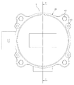
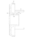
カバー29の詳細を図6および図7を参照して説明する。図6は、図1の左側面図で、図7は、図6のI−I線で矢視したカバー29の縦断面図である。カバー29は、例えば、アルミニウムや亜鉛合金、マグネシウム合金等からなる。カバー29の半径方向外側周辺には、電動アクチュエータ1を組み立て締結するためのボルト61を挿通する貫通孔(図示省略)と、組立てられた電動アクチュエータ1を設置場所に取付けるための貫通孔62が設けられている。
Details of the
図7に示すように、カバー29の円筒部29aの先端部外周面には、軸受装着面63およびスラスト受けリング46の嵌合面64が設けられ、内周には圧縮コイルばね48(図1参照)を収容する凹部29bが形成されている。
As shown in FIG. 7, a
次に、ターミナル部Dを図1〜図5を参照して説明する。図3は、図1のモータ25のステータ23とターミナル部Dを取り出して拡大した図である。図4は、図1のG−G線で矢視した横断面図で、図5は、図1のH−H線で矢視した横断面図である。図3に示すように、ターミナル部Dは、ターミナル本体50と、ターミナル本体50の内部に収容されたバスバー51、プリント基板52とからなる。バスバー51とプリント基板52はターミナル本体50にねじ止めされている。図4および図5に示すように、ステータ23のコイル23cは、一旦、U、V、Wの相別にバスバー51の端子51aに結線され、さらに、図2に示すように、バスバー51の端子51bとターミナル本体50の端子台50aとがねじ70で締結し結線される。ターミナル本体50の端子台50aから延びる端子50bがコントローラ(図12、図13参照)と接続される。端子50bが動力電源用の端子である。なお、信号線は、図1のコネクタ71により接続される。図4および図5に示すように、ターミナル本体50の半径方向外側周辺に組み立て締結用の貫通孔68と取付用の貫通孔69が設けられている。
Next, the terminal part D is demonstrated with reference to FIGS. FIG. 3 is an enlarged view of the
本実施形態の電動アクチュエータ1には、2種類のセンサが搭載されている。これらのセンサを図1、図2、図4および図5を参照して説明する。その一つが、モータ25の回転制御のために用いる回転角度検出用センサ53である。回転角度検出用センサ53としてホール素子が好適である。図1および図5に示すように、回転角度検出用センサ53はプリント基板52に取り付けられている。回転角度検出用センサ53は、図1に示すように、モータ25のロータインナ26の他方の端部(図1の左側)にパルサリング54が取り付けられ、電動アクチュエータ1が組み立てられた状態で、回転角度検出用センサ53と軸方向に隙間をもって対向するように配置されている。回転角度検出用センサ53は、U、V、Wの3相に順番に電流を流すタイミングを決める。
The
残りのセンサが、ボールねじ軸33のストローク制御のために用いるストローク検出用センサ55である。ストローク検出用センサ55もプリント基板52に取り付けられている。図2、図4および図5に示すように、プリント基板52に軸方向に延びる帯状のプリント基板56が接続され、このプリント基板56にストローク検出用センサ55が取り付けられている。プリント基板56およびストローク検出用センサ55は、ボールねじ軸33の中空孔33bに収容されたばね取付カラー36の凹部36cに配置されている。ばね取付カラー36の凹部36cの内周にターゲットとしての永久磁石57が取付けられ、ストローク検出用センサ55と半径方向に間隔をもって対向するように配置されている。これにより、ボールねじ軸33のストローク制御のための信号を取り出すことができる。
The remaining sensors are
本実施形態では、ストローク検出用センサ55を使用した電動アクチュエータ1を例示したが、アプリケーションによっては、ストローク検出用センサ55を使用しない場合もある。
In the present embodiment, the
以上説明した電動アクチュエータ1の全体的な構成による作用効果について、図1を参照してまとめて説明する。ロータインナ26は、一方の端部(図1の右側)のロータコア24aの一端部に近接した軸方向位置に転がり軸受27の内側軌道面27aが形成され、他方の端部(図1の左側)のロータコア24aの他端部に近接した軸方向位置の内周面にころがり軸受30が装着されている。このような構造により、ロータインナ26を軸方向にコンパクトにすることができる。これに加えて、転がり軸受27がボールねじナット32の軸方向幅の内側に配置された構造および、ロータインナ26とボールねじナット32の半径方向の重畳構造が相俟って、図1に示す電動アクチュエータ1の筐体の軸方向寸法L、径方向寸法Mを小さくでき、コンパクトで搭載性が向上する。
The operational effects of the overall configuration of the
ロータコア24aを取り付けたロータインナ26の支持軸受27、30は、ロータの回転バランスが取られているのでロータの自重程度のラジアル荷重を支持できればよい。転がり軸受27は、強度の高い材料を使用する必要がなくロータインナ26の材料である安価な軟鋼等で熱処理としての焼入れも不要である。特に、本実施形態の電動アクチュエータ1では、直線運動の反力は専用の大負荷容量のスラスト針状ころ軸受47で支持される。したがって、転がり軸受27は、ラジアル方向の位置決め機能があればよいため、上記のような材料仕様でよい。これにより、低コスト化が図れる。
The
また、スラスト針状ころ軸受47は、ロータインナ26の両端を支持する転がり軸受27、30間の軸方向範囲内に配置されているので、モーメント荷重に対して有利であり、スラスト軸受を小型化できる。特に、本実施形態のように、スラスト針状ころ軸受47を、ロータインナ26の両端を支持する転がり軸受27、30の軸方向位置の中央部に近い位置に配置した場合は、モーメント荷重に対して極めて有利であり、スラスト軸受の小型化を一層促進できる。その結果、スラスト針状ころ軸受47およびスラスト受けリング46等をサイズダウンでき、電動アクチュエータ1全体のコンパクト化に寄与する。
Further, since the thrust
ターミナル本体50をケーシング20とカバー29とで挟んだサンドイッチ構造にし、端子部を半径方向に形成したので、モータAを収容するケーシング20を長手方向に複数積み重ね、複数の操作部Cを有する電動アクチュエータとすることも可能である。
Since the
本実施形態の電動アクチュエータ1の全体的な構成は以上のとおりである。次に、特徴的な構成を図1、図2、図8〜図11に基づいて説明する。本実施形態の電動アクチュエータ1の特徴的な構成は、要約すると、電動アクチュエータのケーシングを共用化して、回り止めガイド部材をケーシングとは別体にし、ストローク量が異なる回り止めガイド部材をケーシングに付け替え可能にしたものである。これにより、必要なストローク量が異なる用途に対して低コストで対応可能で、シリーズ化に好適なものとなる。
The overall configuration of the
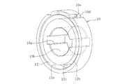
図1、図2および図10に示すように、回り止めガイド部Nを構成する回り止めガイド部材10は、ケーシング20の操作部C側の端部としての円筒部20aとは別体の筒状部品として形成されている。回り止めガイド部材10は、内周面10bにガイドカラー38が嵌め込まれてガイドされる案内溝10aが設けられている。案内溝10aは、電動アクチュエータ1の用途に必要なストローク量が確保できる軸方向の長さを有する。回り止めガイド部材10には、ケーシング20と連結するために環状溝12が形成され、環状溝12は内周面12a、外周面12bおよび底面12cを有する。回り止めガイド部材10の外周面の端部にOリング装着溝10c(図1参照)が設けられている。
As shown in FIGS. 1, 2, and 10, the
環状溝12の内周面12aとケーシング20の円筒部20aの外周面とは、シール性と組立性を考慮して、微小な嵌め合いすきまに設定されている。必要に応じて、環状溝12と円筒部20aとの間にOリング等のシール部材を装着してもよい。環状溝12の底部12cは、ケーシング20の円筒部20aの先端が当接し、回り止めガイド部材10の押し込み方向の位置決めを行う。図2に示すように、環状溝12の底部12cとケーシング20の円筒部20aの先端が当接するまで回り止めガイド部材10を押し込んだ状態でピン13を挿入し、ケーシング20に対する回り止めガイド部材10の軸方向の相対移動と相対回転が防止される。
The inner
回り止めガイド部材10とケーシング20の連結構造Qについて図8および図9を参照して補足する。図8は、図2のF−F線で矢視した一部横断面を含む右側面図で、図9は回り止めガイド部材の組付け方法を説明する正面図である。図示のように、回り止めガイド部材10の環状溝12の内周面12aがケーシング20の円筒部20aの外周面に微小な嵌め合いすきまで嵌合している。回り止めガイド部材10の外周面の2個所に切欠き部10dを設けて、2つの切欠き部10dに貫通するピン孔10eが設けられている。貫通孔としてのピン孔10eに対応してケーシング20の円筒部20aの外周面に円弧断面のキー溝20bが設けられている。
The connection structure Q between the
上記のような形態でピン孔10eとキー溝20bが設けられているので、環状溝12の底部12cとケーシング20の円筒部20aの先端が当接するまで回り止めガイド部材10を横向き白抜き矢印の方向に押し込んだ状態でピン孔10eとキー溝20bが整合し、ピン(スプリングピン)13を上向き白抜き矢印の方向に挿入する。このような組付け方法のため、ケーシング20に対する回り止めガイド部材10の軸方向の相対移動と相対回転をガタつきなく確実に防止でき、回り止めガイド部材10に設けた案内溝10bの回転位相方向の精度も良好である。また、回り止めガイド部材10の組込、連結作業性が容易である。本実施形態では、固定手段として、回り止めガイド部材10に設けられたピン孔10eと、ケーシング20に設けられたキー溝20bと、ピン孔10eとキー溝20bに挿入されるピン13から構成したものを例示したが、これに限られず、例えば、相対回転を防止するキーと止め輪を使用して軸方向の相対移動と相対回転を防止する構造等に適宜変更してもよい。
Since the
次に、図9の回り止めガイド部材10とストローク量が異なる回り止めガイド部材の場合について図11を参照して説明する。図11は、図9と同様、回り止めガイド部材の組付け方法を説明する正面図である。図11に示す回り止めガイド部材10’は、図9の回り止めガイド部材10とストローク量が異なるだけで、その他の構成については、図9の回り止めガイド部材10と同じであるので、回り止めガイド部材には符号10’を付すが、同一の機能を有する各部位には同一の符号を付し、要点のみ説明する。また、図11に示すアクチュエータヘッド39’は、回り止めガイド部材10’のストローク量が増加したことに伴い、図9のアクチュエータヘッド39より軸方向の寸法が増加している。
Next, the case of a non-rotating guide member having a stroke amount different from that of the
図11に示すように、回り止めガイド部材10’は、ストローク量が増加した分、軸方向幅W2は、図9の回り止めガイド部材10の軸方向幅W1より長くなっている。このように、ストローク量は、回り止めガイド部材10,10’の軸方向幅W1、W2に基づいて定まる。また、前述したように、必要なストローク量は用途によって異なる。一方、回り止めガイド部材10’の連結構造Qは、図9の回り止めガイド部材10と形状および寸法が同一に設定されている。そのため、図11に示す回り止めガイド部材10’も、図9の回り止めガイド部材10と同じ組み付け方法で電動アクチュエータ1のケーシング20に組付けられる。換言すれば、図11に示す回り止めガイド部材10’も、図9の回り止めガイド部材10も付け替え可能な、すなわち互換性のある連結構造Qを有している。
As shown in FIG. 11, the rotation preventing guide member 10 'has an axial width W2 longer than the axial width W1 of the rotation preventing
したがって、本実施形態の電動アクチュエータ1では、電動アクチュエータ1の本体(モータ部A、運動変換機構部B、ターミナル部Dやケーシング20等)を共用化して、ストローク量が異なる回り止めガイド部材10、10’をケーシングに付け替えることができる。これにより、必要なストローク量が異なる用途に対して低コストで対応可能で、シリーズ化に好適な電動アクチュエータ1を実現することができる。
Therefore, in the
最後に、図1および図12を参照して本実施形態の電動アクチュエータ1の作動を説明する。図示は省略するが、例えば、車両上位のECUに操作量が入力される。この操作量より、ECUは要求される位置指令値を演算する。図12に示すように、位置指令値が制御装置80のコントローラ81に送られ、コントローラ81は、位置指令値に必要なモータ回転角の制御信号を演算し、この制御信号がコントローラ81からモータ25に送られる。
Finally, the operation of the
制御信号を受け取ったモータ25の中空回転軸であるロータインナ26が回転し、運動変換機構部Bに伝達される。ロータインナ26に連結されたボールねじナット32が回転し、回り止めされたボールねじ軸33が図1の右方向に前進し、コントローラ81の制御信号に基づく位置まで前進し、ボールねじ軸33の一端部(図1の右側)に取付けられたアクチュエータヘッド39が制御対象装置(図示省略)を操作する。
The rotor inner 26 that is the hollow rotating shaft of the
ボールねじ軸33の位置は、図12に示すように、ストロークセンサ55により検出された検出値は、制御装置80の比較部82に送られ、その検出値と位置指令値との差分を算出し、その値と回転角センサ53の信号に基づいて、コントローラ81からモータ25に制御信号が送られ、アクチュエータヘッド39の位置がフィードバック制御される。このため、本実施形態の電動アクチュエータ1を、例えば、シフトバイワイヤに適用した場合、シフト位置を確実にコントロールすることができる。なお、電源は、車両側に設けられたバッテリ等の外部より、制御装置80に入力され(図示省略)、モータや各センサの駆動等に使用される。
As shown in FIG. 12, the position of the
図13にストロークセンサ55を使用しない場合の制御ブロック図を示す。この場合は、圧力制御の例で制御対象装置(図示省略)に圧力センサ83が設けられている。車両上位のECUに操作量が入力されと、ECUは要求される圧力指令値を演算する。この圧力指令値が制御装置80のコントローラ81に送られ、コントローラ81は、圧力指令値に必要なモータの電流値を演算し、コントローラ81からモータ25に送られる。図12の場合と同様に、ボールねじ軸33が図1の右方向に前進する。ボールねじ軸33の一端部に取付けられたアクチュエータヘッド39は制御対象装置(図示省略)を加圧操作する。
FIG. 13 shows a control block diagram when the
アクチュエータヘッド39の操作圧力は、外部設置圧力センサ83により検出され、フィードバック制御される。このため、電動アクチュエータ1を、例えば、ブレーキバイワイヤに適用した場合、ブレーキの液圧を確実にコントロールすることができる。
The operating pressure of the
以上説明したように、本実施形態の電動アクチュエータ1は、小型で搭載性が良く、必要なストローク量が異なる用途に対して低コストで対応可能で、シリーズ化に好適な電動アクチュエータを実現することができる。
As described above, the
本発明は前述した実施形態に何ら限定されるものではなく、本発明の要旨を逸脱しない範囲内において、さらに種々なる形態で実施し得ることは勿論のことであり、本発明の範囲は、特許請求の範囲によって示され、さらに特許請求の範囲に記載の均等の意味、および範囲内のすべての変更を含む。 The present invention is not limited to the above-described embodiments, and can of course be implemented in various forms without departing from the gist of the present invention. It includes the equivalent meanings recited in the claims and the equivalents recited in the claims, and all modifications within the scope.
1 電動アクチュエータ
10 回り止めガイド部材
10a 案内溝
12 環状溝
12a 内周面
12b 外周面
12c 底面
13 ピン
20 ケーシング
20a 円筒部
23 ステータ
23a ステータコア
23b ボビン
23c コイル
24 ロータ
24a ロータコア
24b 永久磁石
25 モータ
26 ロータインナ(中空回転軸)
27 転がり軸受
27a 内側軌道面
27b 外輪
28 軸受ホルダ
29 カバー
30 転がり軸受
31 ボールねじ
32 ボールねじナット
32a 螺旋状溝
32b ボールねじナット外周面
33 ボールねじ軸
33a 螺旋状溝
34 ボール
35 こま
36 ばね取付カラー
37 ピン
38 ガイドカラー
39 アクチュエータヘッド
47 スラスト針状ころ軸受
48 圧縮コイルばね
50 ターミナル本体
51 バスバー
52 プリント基板
53 回転角度検出用センサ
54 パルサリング
55 ストローク検出用センサ
56 プリント基板
57 永久磁石
A モータ部
B 運動変換機構部
C 操作部
D ターミナル部
L 筐体の軸方向寸法
M 筐体の径方向寸法
N 回り止めガイド部
Q 連結構造
DESCRIPTION OF
27 Rolling bearing 27a
Claims (6)
前記ボールねじ軸と回り止めガイド部が凹凸嵌合され、前記ボールねじ軸が前記回り止めガイド部の軸方向幅に基づくストローク量で案内され、
前記回り止めガイド部が前記電動アクチュエータのケーシングとは別体の回り止めガイド部材により形成され、
前記ケーシングの前記操作部側の端部と前記回り止めガイド部材が、当該回り止めガイド部材の付け替えを可能にする連結構造を有することを特徴とする電動アクチュエータ。 An electric actuator including a motor unit, a motion conversion mechanism unit, an operation unit, and a terminal unit, wherein a hollow rotary shaft that supports a rotor core of the motor unit is rotatably supported by a rolling bearing, and the motion conversion mechanism unit is In the electric actuator connected to the hollow rotary shaft and provided with a ball screw, a ball screw nut of this ball screw is disposed inside the hollow rotary shaft, and the operation unit is connected to the motion conversion mechanism unit,
The ball screw shaft and the non-rotating guide portion are unevenly fitted, and the ball screw shaft is guided by a stroke amount based on the axial width of the non-rotating guide portion,
The non-rotating guide part is formed by a non-rotating guide member separate from the casing of the electric actuator,
An electric actuator characterized in that an end portion of the casing on the operation portion side and the anti-rotation guide member have a connection structure that allows the anti-rotation guide member to be replaced.
Priority Applications (2)
| Application Number | Priority Date | Filing Date | Title |
|---|---|---|---|
| JP2016101546A JP2017207182A (en) | 2016-05-20 | 2016-05-20 | Electric actuator |
| PCT/JP2017/017103 WO2017199741A1 (en) | 2016-05-20 | 2017-04-28 | Electric actuator |
Applications Claiming Priority (1)
| Application Number | Priority Date | Filing Date | Title |
|---|---|---|---|
| JP2016101546A JP2017207182A (en) | 2016-05-20 | 2016-05-20 | Electric actuator |
Publications (1)
| Publication Number | Publication Date |
|---|---|
| JP2017207182A true JP2017207182A (en) | 2017-11-24 |
Family
ID=60325069
Family Applications (1)
| Application Number | Title | Priority Date | Filing Date |
|---|---|---|---|
| JP2016101546A Pending JP2017207182A (en) | 2016-05-20 | 2016-05-20 | Electric actuator |
Country Status (2)
| Country | Link |
|---|---|
| JP (1) | JP2017207182A (en) |
| WO (1) | WO2017199741A1 (en) |
Cited By (1)
| Publication number | Priority date | Publication date | Assignee | Title |
|---|---|---|---|---|
| KR20200012518A (en) * | 2018-07-27 | 2020-02-05 | 주식회사 만도 | Steer-By-Wire Type Steering Apparatus |
Citations (11)
| Publication number | Priority date | Publication date | Assignee | Title |
|---|---|---|---|---|
| JPS568928U (en) * | 1979-06-30 | 1981-01-26 | ||
| JPS609342A (en) * | 1983-06-29 | 1985-01-18 | Shinichi Watanabe | Motor with rectilinear motion shaft |
| JPH11287272A (en) * | 1998-03-31 | 1999-10-19 | Tokico Ltd | Disc brake |
| JP2000220715A (en) * | 1999-01-29 | 2000-08-08 | Oriental Motor Co Ltd | Linear actuator |
| JP2005261029A (en) * | 2004-03-10 | 2005-09-22 | Nsk Ltd | Electric actuator |
| JP2005282787A (en) * | 2004-03-30 | 2005-10-13 | Thk Co Ltd | Actuator |
| JP2007040467A (en) * | 2005-08-04 | 2007-02-15 | Nissin Kogyo Co Ltd | Disk brake for vehicle |
| JP4695723B2 (en) * | 2008-04-09 | 2011-06-08 | 篤男 高村 | Cylinder device |
| JP2014018007A (en) * | 2012-07-10 | 2014-01-30 | Nsk Ltd | Electric actuator |
| JP2014088919A (en) * | 2012-10-30 | 2014-05-15 | Ntn Corp | Electric linear actuator |
| JP2016065605A (en) * | 2014-09-25 | 2016-04-28 | セイコークロック株式会社 | Linear drive device and lock device |
-
2016
- 2016-05-20 JP JP2016101546A patent/JP2017207182A/en active Pending
-
2017
- 2017-04-28 WO PCT/JP2017/017103 patent/WO2017199741A1/en active Application Filing
Patent Citations (11)
| Publication number | Priority date | Publication date | Assignee | Title |
|---|---|---|---|---|
| JPS568928U (en) * | 1979-06-30 | 1981-01-26 | ||
| JPS609342A (en) * | 1983-06-29 | 1985-01-18 | Shinichi Watanabe | Motor with rectilinear motion shaft |
| JPH11287272A (en) * | 1998-03-31 | 1999-10-19 | Tokico Ltd | Disc brake |
| JP2000220715A (en) * | 1999-01-29 | 2000-08-08 | Oriental Motor Co Ltd | Linear actuator |
| JP2005261029A (en) * | 2004-03-10 | 2005-09-22 | Nsk Ltd | Electric actuator |
| JP2005282787A (en) * | 2004-03-30 | 2005-10-13 | Thk Co Ltd | Actuator |
| JP2007040467A (en) * | 2005-08-04 | 2007-02-15 | Nissin Kogyo Co Ltd | Disk brake for vehicle |
| JP4695723B2 (en) * | 2008-04-09 | 2011-06-08 | 篤男 高村 | Cylinder device |
| JP2014018007A (en) * | 2012-07-10 | 2014-01-30 | Nsk Ltd | Electric actuator |
| JP2014088919A (en) * | 2012-10-30 | 2014-05-15 | Ntn Corp | Electric linear actuator |
| JP2016065605A (en) * | 2014-09-25 | 2016-04-28 | セイコークロック株式会社 | Linear drive device and lock device |
Cited By (2)
| Publication number | Priority date | Publication date | Assignee | Title |
|---|---|---|---|---|
| KR20200012518A (en) * | 2018-07-27 | 2020-02-05 | 주식회사 만도 | Steer-By-Wire Type Steering Apparatus |
| KR102086428B1 (en) * | 2018-07-27 | 2020-03-09 | 주식회사 만도 | Steer-By-Wire Type Steering Apparatus |
Also Published As
| Publication number | Publication date |
|---|---|
| WO2017199741A1 (en) | 2017-11-23 |
Similar Documents
| Publication | Publication Date | Title |
|---|---|---|
| WO2017130624A1 (en) | Electric actuator | |
| JP6647900B2 (en) | Electric actuator | |
| JP6632909B2 (en) | Electric actuator | |
| WO2017154836A1 (en) | Electrical actuator | |
| JP6762114B2 (en) | Electric actuator | |
| WO2017169855A1 (en) | Electric actuator | |
| WO2017169657A1 (en) | Electric actuator | |
| WO2017169846A1 (en) | Electric actuator | |
| WO2017199741A1 (en) | Electric actuator | |
| WO2017170035A1 (en) | Electric actuator | |
| JP6651381B2 (en) | Electric actuator | |
| JP2018159406A (en) | Electric actuator | |
| JP6621687B2 (en) | Electric actuator | |
| WO2017169935A1 (en) | Electric actuator | |
| JP6736352B2 (en) | Electric actuator |
Legal Events
| Date | Code | Title | Description |
|---|---|---|---|
| A621 | Written request for application examination |
Free format text: JAPANESE INTERMEDIATE CODE: A621 Effective date: 20190426 |
|
| A131 | Notification of reasons for refusal |
Free format text: JAPANESE INTERMEDIATE CODE: A131 Effective date: 20191204 |
|
| A521 | Request for written amendment filed |
Free format text: JAPANESE INTERMEDIATE CODE: A523 Effective date: 20200131 |
|
| A131 | Notification of reasons for refusal |
Free format text: JAPANESE INTERMEDIATE CODE: A131 Effective date: 20200729 |
|
| A521 | Request for written amendment filed |
Free format text: JAPANESE INTERMEDIATE CODE: A523 Effective date: 20200928 |
|
| A131 | Notification of reasons for refusal |
Free format text: JAPANESE INTERMEDIATE CODE: A131 Effective date: 20210331 |
|
| A02 | Decision of refusal |
Free format text: JAPANESE INTERMEDIATE CODE: A02 Effective date: 20211001 |