JP2017207124A - Bearing device for wheel - Google Patents
Bearing device for wheel Download PDFInfo
- Publication number
- JP2017207124A JP2017207124A JP2016099666A JP2016099666A JP2017207124A JP 2017207124 A JP2017207124 A JP 2017207124A JP 2016099666 A JP2016099666 A JP 2016099666A JP 2016099666 A JP2016099666 A JP 2016099666A JP 2017207124 A JP2017207124 A JP 2017207124A
- Authority
- JP
- Japan
- Prior art keywords
- slinger
- flange
- hub shaft
- annular
- slits
- Prior art date
- Legal status (The legal status is an assumption and is not a legal conclusion. Google has not performed a legal analysis and makes no representation as to the accuracy of the status listed.)
- Granted
Links
- 210000000078 claw Anatomy 0.000 claims abstract description 26
- XLYOFNOQVPJJNP-UHFFFAOYSA-N water Substances O XLYOFNOQVPJJNP-UHFFFAOYSA-N 0.000 claims abstract description 24
- 238000005096 rolling process Methods 0.000 claims abstract description 20
- 238000007789 sealing Methods 0.000 description 14
- 230000002093 peripheral effect Effects 0.000 description 8
- 239000000126 substance Substances 0.000 description 7
- 239000002184 metal Substances 0.000 description 4
- 229910000975 Carbon steel Inorganic materials 0.000 description 3
- 239000010962 carbon steel Substances 0.000 description 3
- JEIPFZHSYJVQDO-UHFFFAOYSA-N iron(III) oxide Inorganic materials O=[Fe]O[Fe]=O JEIPFZHSYJVQDO-UHFFFAOYSA-N 0.000 description 3
- 239000010935 stainless steel Substances 0.000 description 2
- 229910001220 stainless steel Inorganic materials 0.000 description 2
- 206010070245 Foreign body Diseases 0.000 description 1
- 230000002159 abnormal effect Effects 0.000 description 1
- 230000006835 compression Effects 0.000 description 1
- 238000007906 compression Methods 0.000 description 1
- 230000006866 deterioration Effects 0.000 description 1
- 238000010586 diagram Methods 0.000 description 1
- 230000005489 elastic deformation Effects 0.000 description 1
- 239000004519 grease Substances 0.000 description 1
- 230000020169 heat generation Effects 0.000 description 1
- 239000000203 mixture Substances 0.000 description 1
- 239000004033 plastic Substances 0.000 description 1
- 239000011347 resin Substances 0.000 description 1
- 229920005989 resin Polymers 0.000 description 1
- 239000000725 suspension Substances 0.000 description 1
Images


Classifications
-
- F—MECHANICAL ENGINEERING; LIGHTING; HEATING; WEAPONS; BLASTING
- F16—ENGINEERING ELEMENTS AND UNITS; GENERAL MEASURES FOR PRODUCING AND MAINTAINING EFFECTIVE FUNCTIONING OF MACHINES OR INSTALLATIONS; THERMAL INSULATION IN GENERAL
- F16C—SHAFTS; FLEXIBLE SHAFTS; ELEMENTS OR CRANKSHAFT MECHANISMS; ROTARY BODIES OTHER THAN GEARING ELEMENTS; BEARINGS
- F16C19/00—Bearings with rolling contact, for exclusively rotary movement
- F16C19/02—Bearings with rolling contact, for exclusively rotary movement with bearing balls essentially of the same size in one or more circular rows
- F16C19/14—Bearings with rolling contact, for exclusively rotary movement with bearing balls essentially of the same size in one or more circular rows for both radial and axial load
- F16C19/18—Bearings with rolling contact, for exclusively rotary movement with bearing balls essentially of the same size in one or more circular rows for both radial and axial load with two or more rows of balls
-
- F—MECHANICAL ENGINEERING; LIGHTING; HEATING; WEAPONS; BLASTING
- F16—ENGINEERING ELEMENTS AND UNITS; GENERAL MEASURES FOR PRODUCING AND MAINTAINING EFFECTIVE FUNCTIONING OF MACHINES OR INSTALLATIONS; THERMAL INSULATION IN GENERAL
- F16C—SHAFTS; FLEXIBLE SHAFTS; ELEMENTS OR CRANKSHAFT MECHANISMS; ROTARY BODIES OTHER THAN GEARING ELEMENTS; BEARINGS
- F16C33/00—Parts of bearings; Special methods for making bearings or parts thereof
- F16C33/72—Sealings
- F16C33/76—Sealings of ball or roller bearings
- F16C33/78—Sealings of ball or roller bearings with a diaphragm, disc, or ring, with or without resilient members
- F16C33/784—Sealings of ball or roller bearings with a diaphragm, disc, or ring, with or without resilient members mounted to a groove in the inner surface of the outer race and extending toward the inner race
- F16C33/7859—Sealings of ball or roller bearings with a diaphragm, disc, or ring, with or without resilient members mounted to a groove in the inner surface of the outer race and extending toward the inner race with a further sealing element
- F16C33/7863—Sealings of ball or roller bearings with a diaphragm, disc, or ring, with or without resilient members mounted to a groove in the inner surface of the outer race and extending toward the inner race with a further sealing element mounted to the inner race, e.g. a flinger to use centrifugal effect
-
- F—MECHANICAL ENGINEERING; LIGHTING; HEATING; WEAPONS; BLASTING
- F16—ENGINEERING ELEMENTS AND UNITS; GENERAL MEASURES FOR PRODUCING AND MAINTAINING EFFECTIVE FUNCTIONING OF MACHINES OR INSTALLATIONS; THERMAL INSULATION IN GENERAL
- F16C—SHAFTS; FLEXIBLE SHAFTS; ELEMENTS OR CRANKSHAFT MECHANISMS; ROTARY BODIES OTHER THAN GEARING ELEMENTS; BEARINGS
- F16C33/00—Parts of bearings; Special methods for making bearings or parts thereof
- F16C33/30—Parts of ball or roller bearings
- F16C33/58—Raceways; Race rings
- F16C33/583—Details of specific parts of races
-
- F—MECHANICAL ENGINEERING; LIGHTING; HEATING; WEAPONS; BLASTING
- F16—ENGINEERING ELEMENTS AND UNITS; GENERAL MEASURES FOR PRODUCING AND MAINTAINING EFFECTIVE FUNCTIONING OF MACHINES OR INSTALLATIONS; THERMAL INSULATION IN GENERAL
- F16C—SHAFTS; FLEXIBLE SHAFTS; ELEMENTS OR CRANKSHAFT MECHANISMS; ROTARY BODIES OTHER THAN GEARING ELEMENTS; BEARINGS
- F16C33/00—Parts of bearings; Special methods for making bearings or parts thereof
- F16C33/30—Parts of ball or roller bearings
- F16C33/66—Special parts or details in view of lubrication
- F16C33/6637—Special parts or details in view of lubrication with liquid lubricant
-
- F—MECHANICAL ENGINEERING; LIGHTING; HEATING; WEAPONS; BLASTING
- F16—ENGINEERING ELEMENTS AND UNITS; GENERAL MEASURES FOR PRODUCING AND MAINTAINING EFFECTIVE FUNCTIONING OF MACHINES OR INSTALLATIONS; THERMAL INSULATION IN GENERAL
- F16C—SHAFTS; FLEXIBLE SHAFTS; ELEMENTS OR CRANKSHAFT MECHANISMS; ROTARY BODIES OTHER THAN GEARING ELEMENTS; BEARINGS
- F16C33/00—Parts of bearings; Special methods for making bearings or parts thereof
- F16C33/72—Sealings
- F16C33/76—Sealings of ball or roller bearings
- F16C33/78—Sealings of ball or roller bearings with a diaphragm, disc, or ring, with or without resilient members
- F16C33/7803—Sealings of ball or roller bearings with a diaphragm, disc, or ring, with or without resilient members suited for particular types of rolling bearings
- F16C33/7806—Sealings of ball or roller bearings with a diaphragm, disc, or ring, with or without resilient members suited for particular types of rolling bearings for spherical roller bearings
-
- F—MECHANICAL ENGINEERING; LIGHTING; HEATING; WEAPONS; BLASTING
- F16—ENGINEERING ELEMENTS AND UNITS; GENERAL MEASURES FOR PRODUCING AND MAINTAINING EFFECTIVE FUNCTIONING OF MACHINES OR INSTALLATIONS; THERMAL INSULATION IN GENERAL
- F16C—SHAFTS; FLEXIBLE SHAFTS; ELEMENTS OR CRANKSHAFT MECHANISMS; ROTARY BODIES OTHER THAN GEARING ELEMENTS; BEARINGS
- F16C33/00—Parts of bearings; Special methods for making bearings or parts thereof
- F16C33/72—Sealings
- F16C33/76—Sealings of ball or roller bearings
- F16C33/78—Sealings of ball or roller bearings with a diaphragm, disc, or ring, with or without resilient members
- F16C33/7816—Details of the sealing or parts thereof, e.g. geometry, material
- F16C33/782—Details of the sealing or parts thereof, e.g. geometry, material of the sealing region
- F16C33/7823—Details of the sealing or parts thereof, e.g. geometry, material of the sealing region of sealing lips
-
- F—MECHANICAL ENGINEERING; LIGHTING; HEATING; WEAPONS; BLASTING
- F16—ENGINEERING ELEMENTS AND UNITS; GENERAL MEASURES FOR PRODUCING AND MAINTAINING EFFECTIVE FUNCTIONING OF MACHINES OR INSTALLATIONS; THERMAL INSULATION IN GENERAL
- F16C—SHAFTS; FLEXIBLE SHAFTS; ELEMENTS OR CRANKSHAFT MECHANISMS; ROTARY BODIES OTHER THAN GEARING ELEMENTS; BEARINGS
- F16C33/00—Parts of bearings; Special methods for making bearings or parts thereof
- F16C33/72—Sealings
- F16C33/76—Sealings of ball or roller bearings
- F16C33/78—Sealings of ball or roller bearings with a diaphragm, disc, or ring, with or without resilient members
- F16C33/7816—Details of the sealing or parts thereof, e.g. geometry, material
- F16C33/782—Details of the sealing or parts thereof, e.g. geometry, material of the sealing region
- F16C33/7826—Details of the sealing or parts thereof, e.g. geometry, material of the sealing region of the opposing surface cooperating with the seal, e.g. a shoulder surface of a bearing ring
-
- F—MECHANICAL ENGINEERING; LIGHTING; HEATING; WEAPONS; BLASTING
- F16—ENGINEERING ELEMENTS AND UNITS; GENERAL MEASURES FOR PRODUCING AND MAINTAINING EFFECTIVE FUNCTIONING OF MACHINES OR INSTALLATIONS; THERMAL INSULATION IN GENERAL
- F16C—SHAFTS; FLEXIBLE SHAFTS; ELEMENTS OR CRANKSHAFT MECHANISMS; ROTARY BODIES OTHER THAN GEARING ELEMENTS; BEARINGS
- F16C33/00—Parts of bearings; Special methods for making bearings or parts thereof
- F16C33/72—Sealings
- F16C33/76—Sealings of ball or roller bearings
- F16C33/78—Sealings of ball or roller bearings with a diaphragm, disc, or ring, with or without resilient members
- F16C33/7816—Details of the sealing or parts thereof, e.g. geometry, material
- F16C33/783—Details of the sealing or parts thereof, e.g. geometry, material of the mounting region
-
- F—MECHANICAL ENGINEERING; LIGHTING; HEATING; WEAPONS; BLASTING
- F16—ENGINEERING ELEMENTS AND UNITS; GENERAL MEASURES FOR PRODUCING AND MAINTAINING EFFECTIVE FUNCTIONING OF MACHINES OR INSTALLATIONS; THERMAL INSULATION IN GENERAL
- F16C—SHAFTS; FLEXIBLE SHAFTS; ELEMENTS OR CRANKSHAFT MECHANISMS; ROTARY BODIES OTHER THAN GEARING ELEMENTS; BEARINGS
- F16C33/00—Parts of bearings; Special methods for making bearings or parts thereof
- F16C33/72—Sealings
- F16C33/76—Sealings of ball or roller bearings
- F16C33/78—Sealings of ball or roller bearings with a diaphragm, disc, or ring, with or without resilient members
- F16C33/784—Sealings of ball or roller bearings with a diaphragm, disc, or ring, with or without resilient members mounted to a groove in the inner surface of the outer race and extending toward the inner race
- F16C33/7859—Sealings of ball or roller bearings with a diaphragm, disc, or ring, with or without resilient members mounted to a groove in the inner surface of the outer race and extending toward the inner race with a further sealing element
- F16C33/7866—Sealings of ball or roller bearings with a diaphragm, disc, or ring, with or without resilient members mounted to a groove in the inner surface of the outer race and extending toward the inner race with a further sealing element with sealing lips
-
- F—MECHANICAL ENGINEERING; LIGHTING; HEATING; WEAPONS; BLASTING
- F16—ENGINEERING ELEMENTS AND UNITS; GENERAL MEASURES FOR PRODUCING AND MAINTAINING EFFECTIVE FUNCTIONING OF MACHINES OR INSTALLATIONS; THERMAL INSULATION IN GENERAL
- F16C—SHAFTS; FLEXIBLE SHAFTS; ELEMENTS OR CRANKSHAFT MECHANISMS; ROTARY BODIES OTHER THAN GEARING ELEMENTS; BEARINGS
- F16C33/00—Parts of bearings; Special methods for making bearings or parts thereof
- F16C33/72—Sealings
- F16C33/76—Sealings of ball or roller bearings
- F16C33/80—Labyrinth sealings
- F16C33/805—Labyrinth sealings in addition to other sealings, e.g. dirt guards to protect sealings with sealing lips
-
- F—MECHANICAL ENGINEERING; LIGHTING; HEATING; WEAPONS; BLASTING
- F16—ENGINEERING ELEMENTS AND UNITS; GENERAL MEASURES FOR PRODUCING AND MAINTAINING EFFECTIVE FUNCTIONING OF MACHINES OR INSTALLATIONS; THERMAL INSULATION IN GENERAL
- F16C—SHAFTS; FLEXIBLE SHAFTS; ELEMENTS OR CRANKSHAFT MECHANISMS; ROTARY BODIES OTHER THAN GEARING ELEMENTS; BEARINGS
- F16C19/00—Bearings with rolling contact, for exclusively rotary movement
- F16C19/02—Bearings with rolling contact, for exclusively rotary movement with bearing balls essentially of the same size in one or more circular rows
- F16C19/14—Bearings with rolling contact, for exclusively rotary movement with bearing balls essentially of the same size in one or more circular rows for both radial and axial load
- F16C19/18—Bearings with rolling contact, for exclusively rotary movement with bearing balls essentially of the same size in one or more circular rows for both radial and axial load with two or more rows of balls
- F16C19/181—Bearings with rolling contact, for exclusively rotary movement with bearing balls essentially of the same size in one or more circular rows for both radial and axial load with two or more rows of balls with angular contact
- F16C19/183—Bearings with rolling contact, for exclusively rotary movement with bearing balls essentially of the same size in one or more circular rows for both radial and axial load with two or more rows of balls with angular contact with two rows at opposite angles
- F16C19/184—Bearings with rolling contact, for exclusively rotary movement with bearing balls essentially of the same size in one or more circular rows for both radial and axial load with two or more rows of balls with angular contact with two rows at opposite angles in O-arrangement
- F16C19/186—Bearings with rolling contact, for exclusively rotary movement with bearing balls essentially of the same size in one or more circular rows for both radial and axial load with two or more rows of balls with angular contact with two rows at opposite angles in O-arrangement with three raceways provided integrally on parts other than race rings, e.g. third generation hubs
-
- F—MECHANICAL ENGINEERING; LIGHTING; HEATING; WEAPONS; BLASTING
- F16—ENGINEERING ELEMENTS AND UNITS; GENERAL MEASURES FOR PRODUCING AND MAINTAINING EFFECTIVE FUNCTIONING OF MACHINES OR INSTALLATIONS; THERMAL INSULATION IN GENERAL
- F16C—SHAFTS; FLEXIBLE SHAFTS; ELEMENTS OR CRANKSHAFT MECHANISMS; ROTARY BODIES OTHER THAN GEARING ELEMENTS; BEARINGS
- F16C2326/00—Articles relating to transporting
- F16C2326/01—Parts of vehicles in general
- F16C2326/02—Wheel hubs or castors
-
- F—MECHANICAL ENGINEERING; LIGHTING; HEATING; WEAPONS; BLASTING
- F16—ENGINEERING ELEMENTS AND UNITS; GENERAL MEASURES FOR PRODUCING AND MAINTAINING EFFECTIVE FUNCTIONING OF MACHINES OR INSTALLATIONS; THERMAL INSULATION IN GENERAL
- F16C—SHAFTS; FLEXIBLE SHAFTS; ELEMENTS OR CRANKSHAFT MECHANISMS; ROTARY BODIES OTHER THAN GEARING ELEMENTS; BEARINGS
- F16C33/00—Parts of bearings; Special methods for making bearings or parts thereof
- F16C33/72—Sealings
- F16C33/76—Sealings of ball or roller bearings
- F16C33/768—Sealings of ball or roller bearings between relatively stationary parts, i.e. static seals
-
- F—MECHANICAL ENGINEERING; LIGHTING; HEATING; WEAPONS; BLASTING
- F16—ENGINEERING ELEMENTS AND UNITS; GENERAL MEASURES FOR PRODUCING AND MAINTAINING EFFECTIVE FUNCTIONING OF MACHINES OR INSTALLATIONS; THERMAL INSULATION IN GENERAL
- F16C—SHAFTS; FLEXIBLE SHAFTS; ELEMENTS OR CRANKSHAFT MECHANISMS; ROTARY BODIES OTHER THAN GEARING ELEMENTS; BEARINGS
- F16C33/00—Parts of bearings; Special methods for making bearings or parts thereof
- F16C33/72—Sealings
- F16C33/76—Sealings of ball or roller bearings
- F16C33/78—Sealings of ball or roller bearings with a diaphragm, disc, or ring, with or without resilient members
- F16C33/7869—Sealings of ball or roller bearings with a diaphragm, disc, or ring, with or without resilient members mounted with a cylindrical portion to the inner surface of the outer race and having a radial portion extending inward
- F16C33/7873—Sealings of ball or roller bearings with a diaphragm, disc, or ring, with or without resilient members mounted with a cylindrical portion to the inner surface of the outer race and having a radial portion extending inward with a single sealing ring of generally L-shaped cross-section
- F16C33/7876—Sealings of ball or roller bearings with a diaphragm, disc, or ring, with or without resilient members mounted with a cylindrical portion to the inner surface of the outer race and having a radial portion extending inward with a single sealing ring of generally L-shaped cross-section with sealing lips
-
- F—MECHANICAL ENGINEERING; LIGHTING; HEATING; WEAPONS; BLASTING
- F16—ENGINEERING ELEMENTS AND UNITS; GENERAL MEASURES FOR PRODUCING AND MAINTAINING EFFECTIVE FUNCTIONING OF MACHINES OR INSTALLATIONS; THERMAL INSULATION IN GENERAL
- F16C—SHAFTS; FLEXIBLE SHAFTS; ELEMENTS OR CRANKSHAFT MECHANISMS; ROTARY BODIES OTHER THAN GEARING ELEMENTS; BEARINGS
- F16C33/00—Parts of bearings; Special methods for making bearings or parts thereof
- F16C33/72—Sealings
- F16C33/76—Sealings of ball or roller bearings
- F16C33/78—Sealings of ball or roller bearings with a diaphragm, disc, or ring, with or without resilient members
- F16C33/7886—Sealings of ball or roller bearings with a diaphragm, disc, or ring, with or without resilient members mounted outside the gap between the inner and outer races, e.g. sealing rings mounted to an end face or outer surface of a race
Landscapes
- Engineering & Computer Science (AREA)
- General Engineering & Computer Science (AREA)
- Mechanical Engineering (AREA)
- Rolling Contact Bearings (AREA)
- Sealing Of Bearings (AREA)
- Sealing With Elastic Sealing Lips (AREA)
Abstract
Description
本発明は、車輪用軸受装置に関するものである。 The present invention relates to a wheel bearing device.
自動車等の車両において、車輪を回転自在に支持するために車輪用軸受装置(ハブユニット)が用いられている。車輪用軸受装置は、車輪が取り付けられるフランジを車両アウタ側に有するハブ軸と、このハブ軸の径方向外側に設けられている外輪と、ハブ軸と外輪との間に設けられている複数の転動体(例えば、複数の玉)と、複数の転動体を保持する保持器とを備えている。また、このような車輪用軸受装置では、ハブ軸と外輪との間であって転動体が設けられている軸受内部に、泥水等の異物が軸受外部から浸入するのを防ぐために、密封装置が設けられている(例えば、特許文献1参照)。 In a vehicle such as an automobile, a wheel bearing device (hub unit) is used to rotatably support a wheel. The wheel bearing device includes a hub shaft having a flange to which a wheel is attached on the vehicle outer side, an outer ring provided radially outside the hub shaft, and a plurality of wheels provided between the hub shaft and the outer ring. A rolling element (for example, a plurality of balls) and a cage that holds the plurality of rolling elements are provided. In addition, in such a wheel bearing device, a sealing device is provided in order to prevent foreign matter such as muddy water from entering the bearing between the hub axle and the outer ring and provided with rolling elements. (For example, refer to Patent Document 1).
従来の密封装置として、外輪の一部にシール部材が取り付けられており、このシール部材のリップをハブ軸の一部に滑り接触させる構成が提案されている。しかし、ハブ軸は、例えば機械構造用炭素鋼からなるため、リップが滑り接触する部分に泥水が付着して錆が発生すると、錆がリップを攻撃してリップの摩耗が促進され、やがて、軸受内部に異物が浸入するおそれがある。 As a conventional sealing device, a structure is proposed in which a seal member is attached to a part of the outer ring, and a lip of this seal member is slidably contacted with a part of the hub shaft. However, because the hub axle is made of carbon steel for machine structure, for example, if muddy water adheres to the part where the lip slides and comes into contact with the rust, the rust attacks the lip and promotes wear of the lip. There is a risk of foreign objects entering the interior.
そこで、図6に示すように、ハブ軸90に環状のスリンガ99(ステンレス製)を取り付け、シール部材93のリップ94をスリンガ99に滑り接触させることで、リップ94の摩耗を防ぐという対策が講じられているものがある。
Therefore, as shown in FIG. 6, an annular slinger 99 (made of stainless steel) is attached to the
スリンガ99は、ハブ軸90の一部(取り付け部91)に外嵌して取り付けられているのみであるため、車両が走行すると、やがてスリンガ99が車両インナ側へ移動することがある(この現象をウォークアウトという)。スリンガ99が車両インナ側(つまり、シール部材93側)へ移動すると、シール部材93のリップ94の締め代が増し、摩擦抵抗が増加して回転損失が大きくなる他、リップ94の異常摩耗や発熱による劣化の原因となってしまう。
Since the
また、前記のようなウォークアウトが発生しなくても、スリンガ99とフランジ92との間に隙間が生じていると、外部からこの隙間を通じて水等が浸入し、ハブ軸90において錆が発生する原因となる。また、水等が前記隙間から浸入し、更に軸受内部にまで到達すると、転動体(玉)96や軌道97を損傷させる原因となり、車輪用軸受装置の寿命を低下させてしまう。
Even if the above walkout does not occur, if a gap is generated between the
そこで、本発明では、車輪用軸受装置において、スリンガがハブ軸の所定位置から移動するのを防ぎ、スリンガとフランジとの間から水等の異物が浸入するのを防止することを目的とする。 Therefore, an object of the present invention is to prevent the slinger from moving from a predetermined position of the hub shaft in the wheel bearing device, and to prevent foreign substances such as water from entering between the slinger and the flange.
本発明の車輪用軸受装置は、車輪が取り付けられるフランジを車両アウタ側に有するハブ軸と、前記ハブ軸の径方向外側に設けられている外輪と、前記ハブ軸と前記外輪との間に設けられている複数の転動体と、前記複数の転動体を保持する保持器と、前記外輪に取り付けられている環状のシール部材と、前記ハブ軸に外嵌して取り付けられ前記シール部材が滑り接触する環状のスリンガと、を備え、前記スリンガは、前記フランジに接触している円環部と、当該円環部から車両インナ側に延びている筒部と、を有し、当該筒部は、車両インナ側に、前記ハブ軸の外周の一部に係合し当該スリンガが車両インナ側に変位するのを阻止する爪部を有し、前記筒部には、更に、車両インナ側で開口するスリットが周方向に沿って複数形成されており、当該複数のスリットには、深さが異なるスリットが含まれている。 A wheel bearing device according to the present invention is provided between a hub shaft having a flange on a vehicle outer side to which a wheel is attached, an outer ring provided radially outside the hub shaft, and the hub shaft and the outer ring. A plurality of rolling elements that are mounted, a cage that holds the plurality of rolling elements, an annular seal member that is attached to the outer ring, and a sliding contact between the seal member that is externally fitted to the hub axle. An annular slinger, and the slinger has an annular portion that is in contact with the flange, and a cylindrical portion that extends from the annular portion toward the vehicle inner side. The vehicle inner side has a claw portion that engages with a part of the outer periphery of the hub shaft and prevents the slinger from being displaced toward the vehicle inner side. The cylinder portion further opens on the vehicle inner side. A plurality of slits are formed along the circumferential direction. , To the plurality of slits, are different are included slit depth.
この車輪用軸受装置によれば、スリンガが有する筒部の爪部がハブ軸の外周の一部に係合し、スリンガが有する円環部がフランジに接触していることで、スリンガがハブ軸の所定位置から移動するのを防ぐことができる。これにより、スリンガとフランジとの間に隙間が生じるのを防ぎ、これらスリンガとフランジとの間から水等の異物が浸入するのを防止することが可能となる。また、前記スリットによれば、スリンガの筒部の剛性を、周方向の位置によって異ならせることができる。つまり、スリットが浅く剛性が高くなる部分により、スリンガとフランジとの間に隙間が生じるのを防ぐ機能を高めることができる。これに対して、スリットが深く剛性が低くなる部分によれば、スリンガをハブ軸に外嵌させ爪部を係合させる際、筒部は弾性変形しやすくなり、スリンガの取り付けが容易となる。 According to this wheel bearing device, the slinger is connected to the hub shaft by engaging the claws of the cylindrical portion of the slinger with a part of the outer periphery of the hub shaft and the ring portion of the slinger contacting the flange. It is possible to prevent movement from a predetermined position. As a result, it is possible to prevent a gap from being generated between the slinger and the flange, and to prevent foreign substances such as water from entering between the slinger and the flange. Moreover, according to the said slit, the rigidity of the cylinder part of a slinger can be varied with the position of the circumferential direction. That is, it is possible to enhance the function of preventing the gap between the slinger and the flange due to the shallow slit and the high rigidity. On the other hand, according to the portion where the slit is deep and the rigidity is low, when the slinger is externally fitted to the hub shaft and the claw portion is engaged, the cylindrical portion is easily elastically deformed, and the slinger is easily attached.
また、前記円環部と前記フランジとの間には環状の止水部材が介在しているのが好ましい。
この構成によれば、スリンガの円環部がフランジに接触した状態で止水部材をこれらにより挟むことができ、スリンガとフランジとの間から水等の異物が浸入するのを防ぐ機能を高めることができる。
Further, it is preferable that an annular water stop member is interposed between the annular portion and the flange.
According to this configuration, the water stopping member can be sandwiched between the slinger with the annular portion in contact with the flange, and the function of preventing foreign substances such as water from entering between the slinger and the flange is enhanced. Can do.
また、スリンガが有する筒部において、剛性が高くなる部分を周方向に沿って均等配置するのが好ましく、そのために、前記筒部の周方向に沿って浅い前記スリットと深い前記スリットとが交互に並んでいるのが好ましい。この構成により、スリンガとフランジとの間から水等の異物が浸入するのを防ぐ機能を全周にわたって高めることができる。また、この場合、剛性が低くなる部分が周方向に沿って均等配置され、ハブ軸に対するスリンガの取り付けが容易となる。 In addition, in the cylindrical portion of the slinger, it is preferable to uniformly arrange the portions with high rigidity along the circumferential direction. For this reason, the shallow slits and the deep slits are alternately arranged along the circumferential direction of the cylindrical portion. It is preferable that they are lined up. With this configuration, it is possible to enhance the function of preventing foreign substances such as water from entering between the slinger and the flange over the entire circumference. Further, in this case, the portions where the rigidity is lowered are evenly arranged along the circumferential direction, and the slinger can be easily attached to the hub axle.
また、前記爪部が係合している前記ハブ軸の外周の一部と前記フランジとの間の軸方向寸法は、自然状態にある前記スリンガの軸方向寸法よりも小さく、当該スリンガが当該ハブ軸に取り付けられた状態で、前記円環部は前記フランジを軸方向に押し付けた状態となるのが好ましい。
この構成により、スリンガとフランジとの間から水等の異物が浸入するのを防止する機能が高まる。また、前記のとおり、複数のスリットには、深さが異なるスリットが含まれていることから、スリットが浅く剛性が高くなる部分により、スリンガの円環部をハブ軸のフランジに対して軸方向に押し付ける作用を強めることができる。
The axial dimension between a part of the outer periphery of the hub shaft engaged with the claw and the flange is smaller than the axial dimension of the slinger in a natural state, and the slinger is the hub. It is preferable that the annular portion is in a state in which the flange is pressed in the axial direction in a state of being attached to the shaft.
With this configuration, the function of preventing foreign substances such as water from entering between the slinger and the flange is enhanced. In addition, as described above, since the plurality of slits include slits having different depths, the slit portion has a shallow and high rigidity, so that the ring portion of the slinger is axially disposed with respect to the flange of the hub shaft. The action of pressing on can be strengthened.
本発明によれば、スリンガがハブ軸の所定位置から移動するのを防ぎ、スリンガとフランジとの間から水等の異物が浸入するのを防ぎ、高い密封性能を確保することが可能となる。 According to the present invention, it is possible to prevent the slinger from moving from a predetermined position of the hub shaft, prevent foreign substances such as water from entering between the slinger and the flange, and ensure high sealing performance.
以下、図面を参照しつつ本発明の実施形態を説明する。
図1は車輪用軸受装置の断面図である。この車輪用軸受装置(ハブユニット)10は、例えば自動車の車体側の懸架装置(ナックル)に取り付けられ、車輪を回転自在に支持するものである。車輪用軸受装置10は、ハブ軸11と、外輪12と、転動体13と、保持器14と、密封装置15,17とを備えている。
Hereinafter, embodiments of the present invention will be described with reference to the drawings.
FIG. 1 is a cross-sectional view of a wheel bearing device. The wheel bearing device (hub unit) 10 is attached to, for example, a suspension device (knuckle) on the vehicle body side of an automobile, and rotatably supports the wheel. The wheel bearing
外輪12は、円筒状の部材であり、例えば機械構造用炭素鋼により製造されている。外輪12は、円筒形状である外輪本体51と、この外輪本体51から径方向外側に延びて設けられている固定用のフランジ部52とを有している。このフランジ部52が車体側部材であるナックル(図示せず)に固定されることで、外輪12を含む車輪用軸受装置10はナックルに固定される。
The
車輪用軸受装置10が車体側に固定された状態で、ハブ軸11が有する後述の車輪取り付け用のフランジ56側が車両の外側となる。つまり、図1の左側(フランジ56側)が車両アウタ側となり、図1の右側が車両インナ側となる。また、図1の左右方向が車輪用軸受装置10の軸方向となる。
In a state where the wheel bearing
外輪12の内周面には、車両アウタ側の外輪軌道面12aと、車両インナ側の外輪軌道面12bとが形成されている。
On the inner peripheral surface of the
ハブ軸11は、軸本体部55と、車輪取り付け用のフランジ56と、内輪部材57とを有している。これらは、例えば機械構造用炭素鋼により製造されている。軸本体部55は軸方向に長い軸部材である。フランジ56は、軸本体部55の車両アウタ側から径方向外側に延びて設けられており、円環形状を有している。フランジ56には、周方向に沿って複数の穴が形成されており、この穴に、車輪取り付け用のボルト69が取り付けられている。フランジ56には、図外の車輪の他にブレーキロータが取り付けられる。内輪部材57は、環状の部材であり、軸本体部55の車両インナ側に嵌合して取り付けられている。軸本体部55の車両アウタ側の外周面に軸軌道面11aが形成され、内輪部材57の外周面に内輪軌道面11bが形成されている。
The
車両アウタ側の外輪軌道面12aと軸軌道面11aとが径方向に対向し、車両インナ側の外輪軌道面12bと内輪軌道面11bとが径方向に対向し、車両アウタ側及びインナ側それぞれの軌道面間に転動体13である玉が配置されている。転動体(玉)13は二列設けられており、各列の転動体(玉)13は、環状の保持器14によって保持されている。ハブ軸11と外輪12との間に複数の転動体13が設けられていることで、外輪12は、ハブ軸11(軸本体部55)の径方向外側においてハブ軸11と同心状に設けられた構成となる。
The outer
車両アウタ側の保持器14は、車両アウタ側に位置する転動体列に含まれる複数の転動体13を、周方向に間隔をあけて保持する。車両インナ側の保持器14は、車両インナ側に位置する転動体列に含まれる複数の転動体13を、周方向に間隔をあけて保持する。保持器14は、例えば樹脂製とすることができる。
The
車両インナ側の密封装置17は、環状のシール部材40と、環状のスリンガ50とによって構成されている。シール部材40は、外輪12(外輪本体51)の内周側であって車両インナ側に嵌合して取り付けられている。スリンガ50は、内輪部材57の外周面に締り嵌めの状態で嵌合して取り付けられている。シール部材40(シール部材40のリップ)が、スリンガ50に滑り接触(摺接)することで、車両インナ側の外部から異物が軸受内部に浸入するのを抑制することができる。軸受内部とは、ハブ軸11と外輪12との間であって、二列の転動体13が設けられている領域である。
The vehicle inner
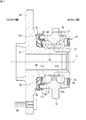
車両アウタ側の密封装置15は、環状のシール部材20と、環状のスリンガ30とによって構成されている。シール部材20は、外輪12(外輪本体51)の内周側であって車両アウタ側に嵌合して取り付けられている。図2は、密封装置15及びその周囲を示す拡大断面図である。スリンガ30は、軸本体部55の車両アウタ側に取り付けられている。シール部材20のリップ21aが、スリンガ30に滑り接触(摺接)することで、車両アウタ側の外部から異物が軸受内部に浸入するのを抑制することができる。
The vehicle outer
シール部材20は、金属製の芯金25と、ゴム製のシール本体26とを有している。芯金25は、外輪12(外輪本体51)の車両アウタ側の端部12cの内周面に締り嵌めの状態で取り付けられている。シール本体26は、芯金25に固定(加硫接着)されており、スリンガ30に滑り接触する第一リップ21aと、スリンガ30との間に隙間を形成している第二リップ21bと、軸本体部55に滑り接触する第三リップ21cとを有している。第一リップ21aは、スリンガ30との間から泥水等の異物が軸受内部に浸入するのを防ぐ機能を有している。第二リップ21bは、第一リップ21aとスリンガ30との滑り接触部分に泥水等の異物が到達するのを抑制する機能を有している。第三リップ21cは、主として軸受内部のグリースが外部へ流出するのを防ぐ機能を有している。第一リップ21aは、スリンガ30に対して軸方向から接触する。第三リップ21cは、軸本体部55に対して径方向から接触する。
The
図2に示すシール本体26は、外輪12(外輪本体51)の車両アウタ側の端部12cの外周面に締め代を有して接触している第四リップ22を更に有している。このリップ22は、外輪12と芯金25との間を通って泥水等の異物が軸受内部に浸入するのを防ぐ機能を有している。
The
スリンガ30は、金属製の環状部材であり、本実施形態ではステンレス製(SUS430)である。スリンガ30は、車両アウタ側の円環部32と、この円環部32から車両インナ側に延びている筒部31とを有している。円環部32は、円環板状となっている部分であり、ハブ軸11のフランジ56の(裾部56bの)側面56aに対して軸方向から接触している。筒部31は、筒形状となっている部分である。
The
車輪用軸受装置10(図1参照)の中心線C(以下、軸受中心線Cという。)を含む断面において(図2参照)フランジ56と軸本体部55との間の部分が凹アール形状となる面58を有していることから、この形状に応じてスリンガ30の筒部31はテーパ筒部31bを有している。つまり、図2及び図3において、筒部31は、車両インナ側の円筒部31aと、この円筒部31aと連続している車両アウタ側のテーパ筒部31bとを有している。円筒部31aは、軸受中心線Cを中心とする仮想の円筒面に沿った形状を有している。テーパ筒部31bは、断面においてアール形状(全体としてテーパ形状)を有している。なお、テーパ筒部31bは、これ以外として、円弧に沿って折り曲げられた形状であってもよい。
In a cross section including a center line C (hereinafter referred to as a bearing center line C) of the wheel bearing device 10 (see FIG. 1) (see FIG. 2), a portion between the
筒部31の円筒部31aは、車両インナ側にハブ軸11(図2参照)の外周の一部に係合している爪部33を有している。本実施形態では、軸本体部55の車両アウタ側の一部(29)の外周面に、周方向に沿って凹部18が形成されており、この凹部18に爪部33が係合している。爪部33は、径方向内側に向かって突出している(折れ曲がっている)部分である。
The
スリンガ30の筒部31のうちの円筒部31aが、軸本体部55の車両アウタ側の一部(29)に締り嵌めの状態で外嵌していると共に、前記爪部33が前記凹部18に係合している。本実施形態の凹部18は、環状の凹溝(周方向に連続している凹溝)からなるが、爪部33の位置に応じて周方向に沿って部分的に(間欠的に)設けられた凹溝であってもよい。ハブ軸11のうち、スリンガ30の筒部31が外嵌して取り付けられている部分(前記一部)を「取り付け部29」とも言う。取り付け部29の外周面は、軸受中心線Cを中心とする円筒面からなる。
The
スリンガ30の円環部32は、フランジ56の(裾部56bの)側面56aに面で接触している。この円環部32がフランジ56に接触している状態で、スリンガ30は車両アウタ側へ変位することができない。
そして、前記筒部31の爪部33が、ハブ軸11の外周の一部(凹部18)に係合していることで、スリンガ30が車両インナ側に変位するのを阻止している。なお、図3に示すように、爪部33は、周方向に沿って複数設けられている。つまり、後に説明するが、筒部31には周方向に沿ってスリット49が複数形成されており、周方向で隣り合うスリット49,49の間がばね片部48となっており、各ばね片部48の先端が、爪部33となっている。なお、全てのばね片部48が爪部33を有していなくてもよく、間欠的に爪部33が設けられていてもよい。ただし、爪部33を周方向に沿って均等配置するのが好ましい。
The
And the
筒部31には、車両インナ側で開口するスリット49が周方向に沿って複数形成されている。図4は、スリット49の説明図である。この説明図では、スリット49の形状の説明を容易とするために、筒部31を平面上に展開した状態として示している。図3及び図4に示すように、複数のスリット49には、深さが異なるスリット(49a,49b)が含まれている。つまり、軸方向に浅いスリット49aと、軸方向に深いスリット49bとが設けられており、筒部31の周方向に沿って浅いスリット49aと深いスリット49bとは交互に並んでいる。
A plurality of
深いスリット49bは、円筒部31aの他に、テーパ筒部31bのうちの円環部32に近い領域まで形成されている。図2では、深いスリット49bを示している。浅いスリット49aは、円筒部31aと、テーパ筒部31bのうちの円筒部31aに近い領域のみに形成されている。なお、浅いスリット49aは、円筒部31aのみに形成されていてもよい。
The
図5は、スリンガ30がハブ軸11から取り外されている状態(取り付け前の状態)を示す説明図である。この状態では、スリンガ30は自然状態にある。スリンガ30がハブ軸11に取り付けられた状態(図2に示す状態)では、スリンガ30は軸方向に圧縮弾性変形している。つまり、図5に示すように、爪部33が係合するハブ軸11の外周の一部(凹部18)とフランジ56(径方向内側面部61)との間の軸方向寸法L1は、取り付け前の自然状態にあるスリンガ30の軸方向寸法L2よりも小さい(L1<L2)。このため、図2に示す取り付け状態では、スリンガ30は軸方向に圧縮弾性変形しており、円環部32がフランジ56を軸方向に(車両アウタ側に向かって)押し付けた状態となっている。スリンガ30の軸方向寸法L2は、円環部32の車両アウタ側の面32bから、爪部33の先端33aまでの軸方向についての寸法である。
FIG. 5 is an explanatory view showing a state where the
スリンガ30の円環部32と、フランジ56との間には環状の止水部材が介在している。図2に示す前記止水部材は、ゴム製のOリング60である。フランジ56の側面56aは、円環部32が面で接触する径方向内側面部61と、この径方向内側面部61と繋がっている径方向外側面部62とを有しており、径方向外側面部62は、径方向内側面部61よりも車両アウタ側に位置している。径方向外側面部62のうち、径方向内側面部61と繋がる部分は曲面形状となっており、この曲面形状の部分と、スリンガ30の円環部32との間にOリング60が介在している。Oリング60は、円環部32及びフランジ56の双方に密着している。
An annular water stop member is interposed between the
図2に示す本実施形態では、スリンガ30は、円環部32の径方向外側の端部32aから車両インナ側に延びている第二の円筒部35を有している。この第二の円筒部35は、シール部材20の第四リップ22の一部の径方向外側に位置している。第二の円筒部35と第四リップ22との間にラビリンス隙間が形成されており、このラビリンス隙間は、第一リップ21aとスリンガ30との滑り接触部分に、外部から泥水等の異物が浸入するのを抑制する機能を有している。
In the present embodiment shown in FIG. 2, the
以上のように、本実施形態の車輪用軸受装置10によれば、スリンガ30の筒部31が有する爪部33がハブ軸11の外周に設けられている凹部18に係合し(図2参照)、スリンガ30の円環部32がフランジ56に接触していることで、スリンガ30がハブ軸11における所定の取り付け位置(取り付け部29)から軸方向に移動するのを防ぐことができる。これにより、スリンガ30とフランジ56との間に隙間が生じるのを防ぎ、これらの間から泥水等の異物が浸入するのを防止することが可能となる。また、スリンガ30の移動を防ぐことで、リップ21aの締め代は所望の一定値に保たれる。以上より、車両アウタ側の密封装置15において、高い密封性能を確保することができる。
As described above, according to the
また、前記のとおり(図5参照)爪部33が係合するハブ軸11の凹部18とフランジ56との間の軸方向寸法L1は、自然状態にあるスリンガ30の軸方向寸法L2よりも小さいことから、このスリンガ30がハブ軸11に取り付けられた状態で、スリンガ30(筒部31)は軸方向に圧縮弾性変形し、これにより円環部32はフランジ56を軸方向に押し付けた状態となる。そして、円環部32とフランジ56との間にはOリング60が介在している。このため、円環部32がフランジ56に接触した状態(軸方向に押し付けた状態)で、これらによりOリング60を挟み更に弾性圧縮変形させることができ、Oリング60に締め代(緊迫力)を持たせ、スリンガ30とフランジ56との間から泥水等の異物が浸入するのを防止する機能を高めている。なお、Oリング60は、フランジ56に対する円環部32の押し付け力が比較的高くなる領域に設けられている。
As described above (see FIG. 5), the axial dimension L1 between the
図4に示すように、スリンガ30の筒部31に形成されている複数のスリット49には、深さが異なるスリット49a,49bが含まれていることから、この筒部31の剛性を、周方向の位置によって異ならせることができる。この構成による機能の一つとして、スリット49が浅く剛性が高くなる部分37により、円環部32をフランジ56に対して軸方向に押し付ける作用を強めている。すなわち、スリンガ30は軸方向に圧縮弾性変形された状態となってハブ軸11に取り付けられるが、スリンガ30のうち、軸方向に長さを有する部分(つまり、筒部31)の剛性を高めることで、前記圧縮弾性変形に基づく反発力(復元力)は部分的に大きくなる。そして、この反発力が、円環部32をフランジ56に押し付ける力となって現れる。そこで、スリット49が浅く剛性が高くなる部分37により前記反発力を部分的に大きくすることで、前記押し付け力が大きくなり、スリンガ30とフランジ56とを密着させ、隙間を防ぐ機能が高まる。
As shown in FIG. 4, the plurality of
スリンガ30の筒部31の剛性を周方向の位置によって異ならせることによる別の機能として、スリット49が深く剛性が低くなる部分38によれば、ハブ軸11に対するスリンガ30の取り付けが容易となる。すなわち、スリンガ30をハブ軸11に外嵌させ爪部33を係合させる際(図5及び図2参照)、爪部33を含むばね片部48を径方向外側に変形させる必要がある。そこで、スリット49が深く剛性が低くなる部分38によれば、筒部31(ばね片部48)は部分的に径方向に弾性変形しやすくなり、この結果、スリンガ30の取り付けが容易となる。
仮に(例えばスリット49が無く)筒部31の全体の剛性が高い場合、ハブ軸11への取り付けのために、筒部31を径方向外側に変形させるとスリンガ30が塑性変形することがある。この場合、爪部33が凹部18に係合しないで脱落する可能性があり、取り付け不良となり、また、前記押し付け力が弱くなるおそれがある。
しかし、本実施形態では、前記のようなスリット49の構成(図4参照)によって、筒部31(ばね片部48)は部分的に径方向に弾性変形しやすくなっており、これにより、スリンガ30が塑性変形してしまうのを防ぐことができる。
As another function by changing the rigidity of the
If the overall rigidity of the
However, in the present embodiment, the cylindrical portion 31 (spring piece portion 48) is partly easily elastically deformed in the radial direction due to the configuration of the slit 49 (see FIG. 4) as described above. 30 can be prevented from plastic deformation.
更に、スリンガ30とフランジ56との間から水等の異物が浸入するのを防ぐ機能を全周にわたって高めるのが好ましい。このために、スリンガ30の筒部31では、剛性が高くなる部分37を周方向に沿って均等配置すればよい。そこで、本実施形態では、筒部31の周方向に沿って浅いスリット49aと深いスリット49bとが交互に並んでいる。なお、この場合、剛性が低くなる部分38が周方向に沿って均等配置され、ハブ軸11に対するスリンガ30の取り付けをより一層、容易としている。
Furthermore, it is preferable to enhance the function of preventing foreign substances such as water from entering between the
以上のとおり開示した実施形態はすべての点で例示であって制限的なものではない。つまり、本発明の車輪用軸受装置は、図示する形態に限らず本発明の範囲内において他の形態のものであってもよい。
例えば、図2に示すスリンガ30は径方向外側に円筒部35を有しているが、この円筒部35は省略されてもよい。また、シール部材20は図示した形状以外であってもよい。
The embodiments disclosed above are illustrative in all respects and not restrictive. That is, the wheel bearing device of the present invention is not limited to the illustrated form, and may be of other forms within the scope of the present invention.
For example, the
10:車輪用軸受装置 11:ハブ軸 12:外輪
13:転動体 14:保持器 20:シール部材
30:スリンガ 31:筒部 32:円環部
33:爪部 49:スリット 49a:浅いスリット
49b:深いスリット 56:フランジ 60:Oリング(止水部材)
L1:軸方向寸法 L2:軸方向寸法
10: Wheel bearing device 11: Hub shaft 12: Outer ring 13: Rolling element 14: Cage 20: Sealing member 30: Slinger 31: Tube part 32: Ring part 33: Claw part 49:
L1: Axial dimension L2: Axial dimension
Claims (4)
前記スリンガは、前記フランジに接触している円環部と、当該円環部から車両インナ側に延びている筒部と、を有し、当該筒部は、車両インナ側に、前記ハブ軸の外周の一部に係合し当該スリンガが車両インナ側に変位するのを阻止する爪部を有し、
前記筒部には、更に、車両インナ側で開口するスリットが周方向に沿って複数形成されており、当該複数のスリットには、深さが異なるスリットが含まれている、車輪用軸受装置。 A hub shaft having a flange to which a wheel is attached on the vehicle outer side, an outer ring provided on the radially outer side of the hub shaft, and a plurality of rolling elements provided between the hub shaft and the outer ring; A retainer that holds the plurality of rolling elements, an annular seal member that is attached to the outer ring, and an annular slinger that is fitted on the hub shaft and is in sliding contact with the seal member;
The slinger has an annular portion that is in contact with the flange, and a cylindrical portion that extends from the annular portion toward the vehicle inner side, and the cylindrical portion is disposed on the vehicle inner side of the hub shaft. A claw portion that engages with a part of the outer periphery and prevents the slinger from being displaced toward the vehicle inner side,
A wheel bearing device in which a plurality of slits opening on the vehicle inner side are formed in the cylindrical portion along the circumferential direction, and the plurality of slits include slits having different depths.
Priority Applications (4)
| Application Number | Priority Date | Filing Date | Title |
|---|---|---|---|
| JP2016099666A JP6686692B2 (en) | 2016-05-18 | 2016-05-18 | Wheel bearing device |
| US15/592,593 US9982719B2 (en) | 2016-05-18 | 2017-05-11 | Wheel bearing apparatus |
| DE102017110414.3A DE102017110414A1 (en) | 2016-05-18 | 2017-05-12 | wheel bearing device |
| CN201710351337.0A CN107401551B (en) | 2016-05-18 | 2017-05-18 | Bearing device for wheel |
Applications Claiming Priority (1)
| Application Number | Priority Date | Filing Date | Title |
|---|---|---|---|
| JP2016099666A JP6686692B2 (en) | 2016-05-18 | 2016-05-18 | Wheel bearing device |
Publications (2)
| Publication Number | Publication Date |
|---|---|
| JP2017207124A true JP2017207124A (en) | 2017-11-24 |
| JP6686692B2 JP6686692B2 (en) | 2020-04-22 |
Family
ID=60255506
Family Applications (1)
| Application Number | Title | Priority Date | Filing Date |
|---|---|---|---|
| JP2016099666A Expired - Fee Related JP6686692B2 (en) | 2016-05-18 | 2016-05-18 | Wheel bearing device |
Country Status (4)
| Country | Link |
|---|---|
| US (1) | US9982719B2 (en) |
| JP (1) | JP6686692B2 (en) |
| CN (1) | CN107401551B (en) |
| DE (1) | DE102017110414A1 (en) |
Cited By (4)
| Publication number | Priority date | Publication date | Assignee | Title |
|---|---|---|---|---|
| JP2020034053A (en) * | 2018-08-28 | 2020-03-05 | 光洋シーリングテクノ株式会社 | Sealing device |
| JP2020070897A (en) * | 2018-11-01 | 2020-05-07 | 光洋シーリングテクノ株式会社 | Sealing device |
| JP2020085032A (en) * | 2018-11-16 | 2020-06-04 | 光洋シーリングテクノ株式会社 | Sealing device |
| US10948018B2 (en) * | 2017-06-28 | 2021-03-16 | Jtekt Corporation | Bearing device for wheel |
Families Citing this family (13)
| Publication number | Priority date | Publication date | Assignee | Title |
|---|---|---|---|---|
| CN112901663B (en) * | 2016-06-20 | 2023-07-25 | Nok株式会社 | Sealing device |
| KR101885139B1 (en) * | 2016-07-25 | 2018-08-03 | 주식회사 일진글로벌 | Sealing apparatus for wheel bearing and manufacturing method thereof |
| JP6921491B2 (en) * | 2016-09-20 | 2021-08-18 | Nok株式会社 | Sealing device |
| US10371210B2 (en) * | 2017-06-13 | 2019-08-06 | Amsted Rail Company, Inc. | Slinger for roller bearing seal, and associated assemblies and methods |
| DE102018103109A1 (en) * | 2018-02-13 | 2019-08-14 | Schaeffler Technologies AG & Co. KG | Wheel bearing assembly with a rotation axis |
| KR102075159B1 (en) * | 2018-04-17 | 2020-02-10 | 주식회사 일진글로벌 | Wheel hub and slinger assembly, wheel bearing assembly, and method of manufacturing wheel hub and slinger assembly |
| US10711842B2 (en) | 2018-05-23 | 2020-07-14 | Amsted Rail Company, Inc. | Roller bearing seal assembly and a component thereof |
| JP7417973B2 (en) * | 2019-03-18 | 2024-01-19 | 内山工業株式会社 | bearing sealing device |
| US20210040991A1 (en) | 2019-08-09 | 2021-02-11 | Amsted Rail Company, Inc. | Roller Bearing Seal Case |
| US11680604B2 (en) | 2020-11-20 | 2023-06-20 | Amsted Rail Company, Inc. | Roller bearing seal assembly |
| IT202100014144A1 (en) * | 2021-05-31 | 2022-12-01 | Skf Ab | SEAL FOR BEARING UNIT |
| DE102022127979A1 (en) * | 2022-10-24 | 2024-04-25 | Schaeffler Technologies AG & Co. KG | roller bearing |
| FR3143693A1 (en) * | 2022-12-16 | 2024-06-21 | Ntn-Snr Roulements | Rolling bearing equipped with a sealing device |
Citations (4)
| Publication number | Priority date | Publication date | Assignee | Title |
|---|---|---|---|---|
| EP1582704A1 (en) * | 2004-04-02 | 2005-10-05 | Corcos Industriale S.p.A. | Valve seal assembly |
| JP2013018478A (en) * | 2011-06-16 | 2013-01-31 | Ntn Corp | Bearing device for wheel |
| JP2014052070A (en) * | 2012-08-08 | 2014-03-20 | Nsk Ltd | Bearing unit for supporting wheel |
| JP2014219032A (en) * | 2013-05-07 | 2014-11-20 | 株式会社ジェイテクト | Bearing device for wheel |
Family Cites Families (19)
| Publication number | Priority date | Publication date | Assignee | Title |
|---|---|---|---|---|
| DE3024397A1 (en) * | 1980-06-28 | 1982-01-21 | Skf Kugellagerfabriken Gmbh | ROLLER BEARING |
| DE3049090A1 (en) * | 1980-12-24 | 1982-07-15 | Skf Kugellagerfabriken Gmbh, 8720 Schweinfurt | ROLLER BEARING |
| ITTO20011061A1 (en) * | 2001-11-09 | 2003-05-09 | Skf Ind Spa | MOUNTING A WHEEL ON THE HUB OF A MOTOR VEHICLE. |
| ITTO20011110A1 (en) * | 2001-11-28 | 2003-05-28 | Skf Ind Spa | DEVICE FOR LOCKING A BEARING IN A WHEEL HUB. |
| JP4371429B2 (en) * | 2007-05-29 | 2009-11-25 | Ntn株式会社 | Wheel bearing device |
| WO2009051047A1 (en) * | 2007-10-15 | 2009-04-23 | Ntn Corporation | Bearing device for wheel |
| CN201502629U (en) * | 2009-08-15 | 2010-06-09 | 山东华泰轴承制造有限公司 | Flanged biserial angular-contact ball ABS bearing unit |
| DE102010064672B3 (en) * | 2010-08-13 | 2019-10-10 | Schaeffler Technologies AG & Co. KG | Sealing arrangement for sealing a wheel bearing |
| CN103703262B (en) * | 2011-06-21 | 2016-04-13 | 日本精工株式会社 | Roller bearing unit |
| CN202896176U (en) * | 2011-10-05 | 2013-04-24 | 日本精工株式会社 | Hub unit |
| JP2013234748A (en) * | 2012-05-11 | 2013-11-21 | Uchiyama Manufacturing Corp | Sealing structure |
| JP2014055651A (en) * | 2012-09-13 | 2014-03-27 | Jtekt Corp | Sealing device and rolling bearing device including the same |
| JP2014095403A (en) | 2012-11-08 | 2014-05-22 | Jtekt Corp | Bearing device for wheel |
| JP6228756B2 (en) | 2013-06-11 | 2017-11-08 | Ntn株式会社 | Wheel bearing device |
| DE102013218635B4 (en) * | 2013-09-17 | 2015-09-24 | Schaeffler Technologies AG & Co. KG | Gasket arrangement for wheel bearings with preloaded spinner plate |
| ITTO20130980A1 (en) * | 2013-11-29 | 2015-05-30 | Skf Ab | LOW FRICTION SEALING COMPLEX, COUPLING SYSTEM WITH A BEARING RING AND WHEEL HUB UNIT EQUIPPED WITH SUCH SEALING COMPLEX |
| JP6748400B2 (en) * | 2014-07-01 | 2020-09-02 | 内山工業株式会社 | Sealing device |
| JP6449622B2 (en) * | 2014-11-07 | 2019-01-09 | 光洋シーリングテクノ株式会社 | Sealing device |
| CN204878358U (en) * | 2015-06-29 | 2015-12-16 | 浙江钧铭机械有限公司 | New seal structure's hub bearing unit |
-
2016
- 2016-05-18 JP JP2016099666A patent/JP6686692B2/en not_active Expired - Fee Related
-
2017
- 2017-05-11 US US15/592,593 patent/US9982719B2/en active Active
- 2017-05-12 DE DE102017110414.3A patent/DE102017110414A1/en not_active Withdrawn
- 2017-05-18 CN CN201710351337.0A patent/CN107401551B/en not_active Expired - Fee Related
Patent Citations (4)
| Publication number | Priority date | Publication date | Assignee | Title |
|---|---|---|---|---|
| EP1582704A1 (en) * | 2004-04-02 | 2005-10-05 | Corcos Industriale S.p.A. | Valve seal assembly |
| JP2013018478A (en) * | 2011-06-16 | 2013-01-31 | Ntn Corp | Bearing device for wheel |
| JP2014052070A (en) * | 2012-08-08 | 2014-03-20 | Nsk Ltd | Bearing unit for supporting wheel |
| JP2014219032A (en) * | 2013-05-07 | 2014-11-20 | 株式会社ジェイテクト | Bearing device for wheel |
Cited By (7)
| Publication number | Priority date | Publication date | Assignee | Title |
|---|---|---|---|---|
| US10948018B2 (en) * | 2017-06-28 | 2021-03-16 | Jtekt Corporation | Bearing device for wheel |
| JP2020034053A (en) * | 2018-08-28 | 2020-03-05 | 光洋シーリングテクノ株式会社 | Sealing device |
| JP7186039B2 (en) | 2018-08-28 | 2022-12-08 | 光洋シーリングテクノ株式会社 | sealing device |
| JP2020070897A (en) * | 2018-11-01 | 2020-05-07 | 光洋シーリングテクノ株式会社 | Sealing device |
| JP7164401B2 (en) | 2018-11-01 | 2022-11-01 | 光洋シーリングテクノ株式会社 | sealing device |
| JP2020085032A (en) * | 2018-11-16 | 2020-06-04 | 光洋シーリングテクノ株式会社 | Sealing device |
| JP7176935B2 (en) | 2018-11-16 | 2022-11-22 | 光洋シーリングテクノ株式会社 | sealing device |
Also Published As
| Publication number | Publication date |
|---|---|
| CN107401551A (en) | 2017-11-28 |
| US20170335890A1 (en) | 2017-11-23 |
| DE102017110414A1 (en) | 2017-11-23 |
| JP6686692B2 (en) | 2020-04-22 |
| US9982719B2 (en) | 2018-05-29 |
| CN107401551B (en) | 2020-09-15 |
Similar Documents
| Publication | Publication Date | Title |
|---|---|---|
| JP6686692B2 (en) | Wheel bearing device | |
| JP6526387B2 (en) | Sealing device | |
| JP2013234748A (en) | Sealing structure | |
| JP6336768B2 (en) | SEALING DEVICE AND WHEEL BEARING DEVICE HAVING THE SAME | |
| JP2010190323A (en) | Sealing device, rolling bearing, and rolling bearing for wheel | |
| JP2017172718A (en) | Wheel bearing device | |
| CN107131214B (en) | Bearing device for wheel | |
| JP2020020351A (en) | Wheel support rolling bearing unit | |
| JP2010281386A (en) | Sealing device, rolling bearing and rolling bearing for wheel | |
| JP2015224746A (en) | Rolling bearing device for wheel | |
| JP6477204B2 (en) | Method of assembling bearing device for wheel | |
| JP2009074589A (en) | Sealing device | |
| JP2019190608A (en) | Sealing device | |
| JP6772544B2 (en) | Rolling bearing equipment | |
| JP5293420B2 (en) | Sealing device | |
| JP2009024807A (en) | Sealing device | |
| JP2009287651A (en) | Bearing device for wheel | |
| JP4893550B2 (en) | Sealing device | |
| JP2009024809A (en) | Sealing device and rolling bearing device | |
| JP6848350B2 (en) | Bearing device for wheels | |
| JP6658216B2 (en) | Wheel bearing device | |
| JP2009024804A (en) | Sealing device | |
| JPWO2008050746A1 (en) | Sealing device, rolling bearing and wheel rolling bearing | |
| JP6759594B2 (en) | Bearing device for wheels | |
| JP2016070306A (en) | Sealed roller bearing |
Legal Events
| Date | Code | Title | Description |
|---|---|---|---|
| A621 | Written request for application examination |
Free format text: JAPANESE INTERMEDIATE CODE: A621 Effective date: 20190415 |
|
| TRDD | Decision of grant or rejection written | ||
| A01 | Written decision to grant a patent or to grant a registration (utility model) |
Free format text: JAPANESE INTERMEDIATE CODE: A01 Effective date: 20200303 |
|
| A61 | First payment of annual fees (during grant procedure) |
Free format text: JAPANESE INTERMEDIATE CODE: A61 Effective date: 20200316 |
|
| R150 | Certificate of patent or registration of utility model |
Ref document number: 6686692 Country of ref document: JP Free format text: JAPANESE INTERMEDIATE CODE: R150 |
|
| LAPS | Cancellation because of no payment of annual fees |