JP2017206809A - Disaster prevention warehouse - Google Patents
Disaster prevention warehouse Download PDFInfo
- Publication number
- JP2017206809A JP2017206809A JP2016097605A JP2016097605A JP2017206809A JP 2017206809 A JP2017206809 A JP 2017206809A JP 2016097605 A JP2016097605 A JP 2016097605A JP 2016097605 A JP2016097605 A JP 2016097605A JP 2017206809 A JP2017206809 A JP 2017206809A
- Authority
- JP
- Japan
- Prior art keywords
- disaster prevention
- storage battery
- warehouse
- prevention warehouse
- voltage drop
- Prior art date
- Legal status (The legal status is an assumption and is not a legal conclusion. Google has not performed a legal analysis and makes no representation as to the accuracy of the status listed.)
- Pending
Links
Images


Abstract
Description
本発明は、防災用具を収容しておく防災用倉庫に関する。 The present invention relates to a disaster prevention warehouse that stores disaster prevention tools.
防災用倉庫として、太陽電池パネルと蓄電池と屋外灯とを備えて、夜間に屋外灯が蓄電池から受電して自動点灯するものが知られている(例えば、特許文献1参照)。 As a disaster prevention warehouse, a solar cell panel, a storage battery, and an outdoor lamp are known, and the outdoor lamp receives power from the storage battery at night and is automatically turned on (see, for example, Patent Document 1).
しかしながら、従来の防災用倉庫では、防災用に備えた蓄電池が、災害時に寿命切れになっていて十分な電力供給を行えない事態が起こり得た。 However, in a conventional disaster prevention warehouse, there may have been a situation in which a storage battery prepared for disaster prevention has expired at the time of a disaster and cannot supply sufficient power.
本発明は、上記事情に鑑みてなされたもので、防災用に備えた蓄電池が、災害時に寿命切れになっていることを防ぐことが可能な防災用倉庫の提供を目的とする。 This invention is made | formed in view of the said situation, and it aims at provision of the warehouse for disaster prevention which can prevent that the storage battery provided for disaster prevention has expired at the time of a disaster.
上記目的を達成するためになされた請求項1の発明は、太陽電池パネルと、前記太陽電池パネルにて蓄電される蓄電池と、夜間にのみ前記蓄電池から給電されて自動点灯する屋外灯とを備える防災用倉庫であって、前記屋外灯に給電中の前記蓄電池の電圧降下率が、予め定められた基準値より大きいか否かを判定する劣化判定手段と、前記電圧降下率が前記基準値より大きい場合に、そのことを報知する報知手段とを備える防災用倉庫である。 The invention of claim 1 made to achieve the above object comprises a solar battery panel, a storage battery stored in the solar battery panel, and an outdoor lamp that is powered from the storage battery and automatically lit only at night. Deterioration determining means for determining whether or not the voltage drop rate of the storage battery that is feeding power to the outdoor lamp is greater than a predetermined reference value, and the voltage drop rate is more than the reference value. When it is large, it is a disaster prevention warehouse provided with a notifying means for notifying that fact.
請求項2の発明は、前記屋外灯を含む複数の負荷と、前記屋外灯が自動点灯してから前記劣化判定手段による判定が終了する迄の検出期間中は、前記蓄電池から受電可能な負荷を前記屋外灯を含む一定の負荷に制限し、前記検出期間の経過後には、任意の前記負荷を前記蓄電池から受電可能にするタイムスケジューラーとを備える請求項1に記載の防災用倉庫である。 The invention of claim 2 includes a plurality of loads including the outdoor lamp and a load that can receive power from the storage battery during a detection period from when the outdoor lamp is automatically turned on until the determination by the deterioration determining unit is completed. 2. The disaster prevention warehouse according to claim 1, further comprising a time scheduler that limits the load to a constant load including the outdoor light and enables the arbitrary load to receive power from the storage battery after the detection period has elapsed.
請求項3の発明は、前記蓄電池の出力電圧を100[V]の交流電圧に変換するインバータ回路と、前記インバータ回路の出力に任意の充電式電気機器を接続するためのコンセントとを備え、前記タイムスケジューラーは、予め定められた一定期間に限り前記インバータ回路を前記蓄電池から受電可能にする請求項2に記載の防災用倉庫である。 Invention of Claim 3 is provided with the inverter circuit which converts the output voltage of the said storage battery into the alternating voltage of 100 [V], and the outlet socket for connecting arbitrary rechargeable electric equipment to the output of the said inverter circuit, The time scheduler is a warehouse for disaster prevention according to claim 2, wherein the inverter circuit can receive power from the storage battery only for a predetermined period.
請求項4の発明は、防災用倉庫の内部に設けられている屋内灯と、前記タイムスケジューラーとは無関係に、前記屋内灯を前記蓄電池に接続可能とする手動スイッチとを備える請求項2乃至3の何れか1の請求項に記載の防災用倉庫である。 Invention of Claim 4 is provided with the indoor switch provided in the inside of the warehouse for disaster prevention, and the manual switch which can connect the said indoor light to the said storage battery irrespective of the said time scheduler. It is a warehouse for disaster prevention given in any 1 claim.
請求項5の発明は、前記基準値が複数設定され、前記報知手段は、前記電圧降下率が各前記基準値を超える毎に報知態様を段階的に変えて報知を行う請求項1乃至4の何れか1の請求項に記載の防災用倉庫である。 According to a fifth aspect of the present invention, a plurality of the reference values are set, and the notification means performs notification by changing the notification mode step by step every time the voltage drop rate exceeds each of the reference values. It is a warehouse for disaster prevention according to any one of the claims.
請求項6の発明は、防災用倉庫の外部から視認可能な位置に配置された報知用LEDを前記報知手段として備える請求項1乃至5の何れか1の請求項に記載の防災用倉庫である。 The invention according to claim 6 is the disaster prevention warehouse according to any one of claims 1 to 5, wherein the notification means is provided with a notification LED arranged at a position visible from the outside of the disaster prevention warehouse. .
請求項7の発明は、防災用倉庫の外面に防災を意味する表示部が設けられ、前記屋外灯は前記表示部を照らすように配置されている請求項1乃至6の何れか1の請求項に記載の防災用倉庫である。 The invention according to claim 7 is provided with a display unit indicating disaster prevention on an outer surface of the disaster prevention warehouse, and the outdoor lamp is arranged to illuminate the display unit. It is a warehouse for disaster prevention as described in.
蓄電池が劣化すると蓄電可能な容量が減少するので、同じ負荷が接続されている状態下では、劣化が進むに従って、蓄電池の電圧降下率(即ち、蓄電池の出力電圧の単位時間当りの降圧量)が大きくなる。そして、請求項1の防災用倉庫では、屋外灯に給電中の蓄電池の電圧降下率が基準値より大きくなっている場合にそのことが報知される。これにより、寿命切れが近い蓄電池の交換が促され、災害時に蓄電池が寿命切れになっていることを防ぐことができる。 Since the capacity that can be stored decreases when the storage battery deteriorates, the voltage drop rate of the storage battery (that is, the step-down amount per unit time of the output voltage of the storage battery) increases as the deterioration progresses under the same load connected condition. growing. And in the warehouse for disaster prevention of Claim 1, that is alert | reported when the voltage drop rate of the storage battery currently supplying electric power to an outdoor lamp is larger than a reference value. Thereby, replacement | exchange of the storage battery near expiration of a lifetime is promoted, and it can prevent that the storage battery has expired at the time of a disaster.
請求項2の防災用倉庫では、屋外灯が自動点灯してから蓄電池の劣化の判定が終了する迄の検出期間中は、蓄電池から受電可能な負荷が、屋外灯を含む一定の負荷に制限される。また、検出期間の経過後には、任意の負荷が蓄電池から受電可能になる。これにより、毎日、日没後に同じ負荷条件で電圧降下率が検出されて判定され、蓄電池の劣化状態を正確に判断することが可能になる。 In the warehouse for disaster prevention according to claim 2, during a detection period from when the outdoor light is automatically turned on until the determination of the deterioration of the storage battery is completed, the load that can receive power from the storage battery is limited to a certain load including the outdoor light. The Further, after the detection period has elapsed, an arbitrary load can receive power from the storage battery. As a result, the voltage drop rate is detected and determined every day after sunset under the same load condition, and the deterioration state of the storage battery can be accurately determined.
請求項3の防災用倉庫では、蓄電池から受電して作動するインバータ回路を備えたことにより、通常は、商用電源で充電される任意の充電式電気機器を蓄電池からの電力によって充電することができる。ここで、充電式電気機器の充電が完了していても、インバータ回路が作動しているとそのインバータ回路自体が電力を消費することになるが、タイムスケジューラーによりインバータ回路が蓄電池から受電可能な期間が制限されているので、無駄な電力消費を抑えることができる。 In the disaster prevention warehouse according to claim 3, by providing an inverter circuit that operates by receiving power from the storage battery, any rechargeable electric device that is normally charged by a commercial power source can be charged by the power from the storage battery. . Here, even if charging of the rechargeable electrical device is completed, if the inverter circuit is operating, the inverter circuit itself consumes power, but the time scheduler allows the inverter circuit to receive power from the storage battery. Is limited, and wasteful power consumption can be suppressed.
実際に災害が発生した状況下では蓄電池の劣化の監視は不要になり、夜間に防災用倉庫を使用するときには、防災用倉庫内の照明が必要になる。これらに対し、請求項4の防災用倉庫では、タイムスケジューラーとは無関係に、手動スイッチにより屋内灯をオンして収容空間を照らすことができるので利便性に優れる。 Monitoring of deterioration of the storage battery is unnecessary under the situation where a disaster actually occurs, and lighting in the disaster prevention warehouse is necessary when using the disaster prevention warehouse at night. On the other hand, the disaster prevention warehouse of claim 4 is excellent in convenience because it can illuminate the accommodation space by turning on the indoor lamp with a manual switch regardless of the time scheduler.
請求項5の防災用倉庫によれば、蓄電池の劣化が進行するに従って報知態様が段階的に変わるので、電池交換を効果的に促すことができる。 According to the warehouse for disaster prevention of claim 5, since the notification mode changes stepwise as the storage battery progresses, battery replacement can be effectively promoted.
請求項6の防災用倉庫では、蓄電池の劣化を報知する報知用LEDが防災用倉庫の外部から視認可能な位置に配置されているので、逐一、防災用倉庫を開かずに、蓄電池の劣化を容易に確認することができる。 In the disaster prevention warehouse according to claim 6, since the notification LED for notifying the deterioration of the storage battery is arranged at a position that can be visually recognized from the outside of the disaster prevention warehouse, the storage battery is deteriorated without opening the disaster prevention warehouse one by one. It can be easily confirmed.
請求項7の防災用倉庫では、屋外灯が防災用倉庫の外面に設けられた防災を意味する表示部を照らすので、夜間の災害時に容易に防災用倉庫を見つけることができる。 In the disaster prevention warehouse according to the seventh aspect, since the outdoor lamp illuminates the display part that means disaster prevention provided on the outer surface of the disaster prevention warehouse, the disaster prevention warehouse can be easily found during a nighttime disaster.
以下、本発明の一実施形態を図1〜図6に基づいて説明する。図1には、本実施形態の防災用倉庫10の外観が示されている。この防災用倉庫10の本体部分は、一般には所謂「物置」として市販されているものと同じ構造をなしている。具体的には、防災用倉庫10は、全体が直方体状をなし、前面に2枚の引戸12A,12Aを有する。それら引戸12A,12Aの外面には、この倉庫10が防災用であることを表示する表示部13が備えられている。なお、引戸12A,12Aには、錠装置12Kが備えられているが、常に解錠されている。
Hereinafter, an embodiment of the present invention will be described with reference to FIGS. FIG. 1 shows the appearance of the
防災用倉庫10の前面のうち引戸12A,12Aより上側の縁部には、その横方向の中央に屋外灯17が取り付けられている。屋外灯17は、LEDを発光源として備え、例えば、下方に向けて光を出射する構造をなし、その光の一部によって表示部13を照射する。これにより、防災用倉庫10を離れた位置から視認した際に、表示部13を容易に読み取ることができ、屋外灯17からの直接光は看者の目に入らない。
An
防災用倉庫10の上面には、太陽電池パネル15(「太陽電池モジュール」ともいう)が取り付けられている。太陽電池パネル15の受光面の面積は、防災用倉庫10の上面の面積に比べて例えば1/10以下になっていて、防災用倉庫10の上面のうち一側面寄り位置に配置されている。また、太陽電池パネル15は、支持脚部15Kにより効率良く太陽光を受けることが可能な姿勢に保持されている。
A solar cell panel 15 (also referred to as a “solar cell module”) is attached to the upper surface of the
防災用倉庫10のうち太陽電池パネル15に近い側の側面には、制御ボックス16が取り付けられている。また、制御ボックス16の一側面は回動扉16Fになっている。なお、制御ボックス16の上面は一側面側に向かって下るように傾斜している。
A
図2(A)に示すように、制御ボックス16の内部には、充放電コントローラ20、蓄電池21、インバータ回路22及び電圧降下率検出回路23とが収容されている。また、太陽電池パネル15から延びたケーブル15C(図1参照)が制御ボックス16内に引き込まれて充放電コントローラ20に接続されている。
As shown in FIG. 2A, the
図2(B)に示すように、防災用倉庫10内の天井面の前縁部には、その横方向の中央に屋内灯18が取り付けられ、両端部に操作スイッチ19,19が設けられている。なお、屋内灯18は、屋外灯17と同様にLEDを発光源としている。
As shown in FIG. 2B, an
制御ボックス16が取り付けられた防災用倉庫10の側壁の内面には中継ボックス30が取り付けられている。また、側壁に形成された図示しない貫通孔に通したハーネスが制御ボックス16と中継ボックス30とを連絡している。そして、中継ボックス30に備えた図示しない端子台を介して充放電コントローラ20、蓄電池21、屋外灯17,屋内灯18等とが接続されて、図3に示した電気回路が構成されている。以下、この電気回路について詳説する。
A
太陽電池パネル15の正負の電極間には、充放電コントローラ20を介して、蓄電池21と、本発明に係る「複数の負荷」としての、屋外灯17と屋内灯18とインバータ回路22とが並列接続されている。換言すれば、電源としての太陽電池パネル15及び蓄電池21の正負の電極間に、屋外灯17等の複数の負荷が並列接続されている。そして、蓄電池21より太陽電池パネル15の出力電圧が高い場合には、太陽電池パネル15の出力電圧が各負荷に印加され、逆に、太陽電池パネル15より蓄電池21の出力電圧が高い場合には、蓄電池21の出力電圧が各負荷に印加される。即ち、夜間は、蓄電池21の出力電圧が各負荷に印加される。なお、太陽電池パネル15及び蓄電池21の負極は、グランドに接続されている。
Between the positive and negative electrodes of the
太陽電池パネル15及び蓄電池21の正負の電極間には、各負荷と共にスイッチが直列接続されている。具体的には、屋内灯18に対応してタイマースイッチ25が設けられ、屋外灯17に対応して充放電コントローラ20に内蔵された屋外灯スイッチ29が設けられ、インバータ回路22に対応してタイムスケジューラー26の内蔵スイッチ26S1が設けられている。このタイマースイッチ25は、通常はオフ状態になっていて、防災用倉庫10内の1対の操作スイッチ19,19の何れかが手動操作されると、所定時間(例えば、3分)に亘ってオン状態が維持され、所定時間の経過後にオフする。なお、タイマースイッチ25は、オン状態になっているときには電力を消費し、太陽電池パネル15及び蓄電池21にとっての負荷になる。
A switch is connected in series with each load between the positive and negative electrodes of the
タイムスケジューラー26は、上記内蔵スイッチ26S1の他にも複数の内蔵スイッチ26S2,26S3,・・・を有し、後述する検出期間を除いた時間帯で、予め定められたタイムスケジュールに従って各内蔵スイッチ26S1,26S2,26S3,・・・をオンオフする。これにより、任意の負荷を、太陽電池パネル15及び蓄電池21に導通接続したり、断絶することができる。そのために、タイムスケジューラー26は例えば図示しないマイコンを備えて電力を常時消費し、この点において、タイムスケジューラー26も太陽電池パネル15及び蓄電池21にとっての負荷になる。
The
インバータ回路22は、例えばマイコンで複数のFETをスイッチングして直流を交流に変換する一般的な回路構成を有する。また、インバータ回路22の出力は、中継ボックス30に設けられたコンセント31に接続されている。そして、そのコンセント31には、例えば、災害時に必要になる充電式の無線通話機27(本発明の「充電式電気機器」に相当する)から延びたプラグが接続されている。ここで、コンセント31に無線通話機27等の負荷が接続されていない状態でも、インバータ回路22は、FETをオンオフしているので電力を消費する。これに鑑み、タイムスケジューラー26は、インバータ回路22を作動させる時間を一定時間(例えば、2時間)に制限している。
The
充放電コントローラ20には、マイコン20Mと、太陽電池パネル15の発電量P1を検出する電力量検出回路28とが備えられている。そして、マイコン20Mが、例えば図4に示した点灯制御プログラムPG1を所定周期(例えば、10分)で実行して、電力量検出回路28の検出結果に基づいて屋外灯スイッチ29をオンオフ制御する。
The charge /
即ち、点灯制御プログラムPG1が実行されると、最初に、FLG1が「1」になっているか否かをチェックする(S10)。ここで、FLG1が「1」になっていない場合は(S10でNO)、屋外灯17が点灯していないことを意味し、その場合は、太陽電池パネル15の発電量P1が、第1閾値K1以下であるか否かをチェックする(S11)。そして、太陽電池パネル15の発電量P1が第1閾値K1以下であれば(S11でYES)、夜になったと判断して屋外灯スイッチ29をオンして屋外灯17を点灯しかつ(S12)、FLG1を「1」にセットしてから(S13)、この点灯制御プログラムPG1を抜ける。一方、太陽電池パネル15の発電量P1が第1閾値K1以下でなければ(S11でNO)、夜になっていないと判断して直ちにこの点灯制御プログラムPG1を抜ける。
That is, when the lighting control program PG1 is executed, it is first checked whether FLG1 is “1” (S10). Here, if FLG1 is not “1” (NO in S10), it means that the
一方、最初に、FLG1が「1」になっているか否かをチェックしたときに(S10)、FLG1が「1」になっている場合は(S10でYES)、屋外灯17が点灯していることを意味し、その場合は、太陽電池パネル15の発電量P1が、第2閾値K2以上であるか否かを判別する(S14)。そして、太陽電池パネル15の発電量P1が第2閾値K2以上であれば(S14でYES)、夜が明けていると判断して屋外灯スイッチ29をオフして屋外灯17を消灯しかつ(S15)、FLG1を「0」にリセットして(S16)、この点灯制御プログラムPG1を抜ける。一方、太陽電池パネル15の発電量P1が第2閾値K2以上でなければ(S14でNO)、夜が明けていないと判断して直ちにこの点灯制御プログラムPG1から抜ける。
On the other hand, when it is first checked whether FLG1 is “1” (S10), if FLG1 is “1” (YES in S10), the
これにより、屋外灯17は、夜間にのみ蓄電池21から受電して自動点灯する。なお、第1閾値K1より第2閾値K2は大きな値に設定されていて、これにより、日没時及び日の出時に、屋外灯スイッチ29のオンオフが頻繁に切り替わることが防がれている。
Thereby, the
図3に示すように、蓄電池21から屋外灯17への導電ラインの途中には、電圧降下率検出回路23が接続されている。電圧降下率検出回路23は、図示しない電圧検出回路及びマイコンと3色LED24とを備えている。その3色LED24は、図1及び図2に示すように、制御ボックス16のうち防災用倉庫10の前方を向いた面に取り付けられている。
As shown in FIG. 3, a voltage drop
マイコンは、屋外灯スイッチ29がオンしたことをトリガにして図5に示した劣化判別プログラムPG2を実行する。劣化判別プログラムPG2が実行されると、蓄電池21の出力電圧を第1電圧E1として検出し(S20)、次いでタイマーを起動して(S21)、そのタイマーが一定時間T1(例えば、1時間)を計時したら(S22でYES)、蓄電池21の出力電圧を第2電圧E2として検出する(S23)。そして、これら第1電圧E1と第2電圧E2と一定時間T1とから、単位時間当たりの蓄電池21の出力電圧の降下量を電圧降下率R1(=(E1−E2)/T1)として演算する(S24)。
The microcomputer executes the deterioration determination program PG2 shown in FIG. 5 by using the outdoor
そして、電圧降下率R1が第1基準値X1未満であれば(S25でYES)、3色LED24を緑色に点灯させ(S27)、電圧降下率R1が第1基準値X1以上で第2基準値X2未満であれば(S25でNO、S26でNO)、3色LED24を黄色に点灯させ(S28)、電圧降下率R1が第2基準値X2以上であれば(S25でNO、S26でYES)、3色LED24を赤色に点灯させて(S29)、この劣化判別プログラムPG2から抜ける。即ち、タイマースイッチ25は、毎日、屋外灯17が点灯してから一定時間T1(例えば、1時間)が経過する迄の間に、蓄電池21の電圧降下率の判定を行って、その判定結果を3色LED24を用いて報知する。
If the voltage drop rate R1 is less than the first reference value X1 (YES in S25), the three-
なお、本実施形態では、タイマースイッチ25のうち劣化判別プログラムPG2のステップS20〜S26を実行しているときのマイコンが、本発明に係る劣化判定手段に相当し、劣化判別プログラムPG2のステップS27〜S29を実行しているときのマイコンと3色LED24とが本発明に係る報知手段に相当する。また、屋外灯17が点灯してからタイマースイッチ25による判定が終わるまでの期間が上記した検出期間に相当する。
In the present embodiment, the microcomputer when executing steps S20 to S26 of the deterioration determination program PG2 in the
本実施形態の防災用倉庫10の構成に関する説明は以上である。この防災用倉庫10は、地震や水害等の災害からの避難場所に設置され、ヘルメット、救急箱、防寒具、ラジオ、非常食等の防災用品を収容して使用される。そして、日中に太陽電池パネル15により発電を行って蓄電池21を充電し、夜間に蓄電池21により屋外灯17を点灯する動作を毎日繰り返す。
This completes the description of the configuration of the
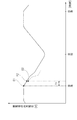
ここで、図6に示すように、1日の蓄電池21の出力電圧の推移が示されている。蓄電池21の出力電圧は、日出前に最低になり、日出後に太陽電池パネル15による充電が開始されてから徐々に高くなる。なお、日中も、電圧降下率検出回路23やタイムスケジューラー26やタイムスケジューラー26にて太陽電池パネル15に接続されている電気機器等が作動するが、それらの消費電力量に比べて太陽電池パネル15による発電量が多いので蓄電池21が充電されていく。そして、日中に蓄電池21の充電が完了して蓄電池21の出力電圧が一定になる。また、日が沈むと屋外灯17が点灯し、蓄電池21の電力を消費する。
Here, as shown in FIG. 6, the transition of the output voltage of the
ここで、蓄電池21が劣化すると蓄電可能な容量が減少するので、同じ負荷が接続されている状態下では、劣化が進むと、図6の破線に示すように蓄電池21の電圧降下率R1が大きくなる。これに対し、本実施形態の防災用倉庫10では、日没後、一定の検出期間の間は、毎日、屋外灯17と電圧降下率検出回路23とタイムスケジューラー26とからなる限られた負荷のみが蓄電池21が電力を受けれるように制限して、その検出期間における蓄電池21の電圧降下率を電圧降下率検出回路23が検出し、その電圧降下率の大きさに応じた色で3色LED24を発光させる。
Here, when the
これにより、防災用倉庫10の管理者は、防災用倉庫10の外側から3色LED24を視認して、蓄電池21の劣化状態を確認することができる。具体的には、3色LED24が緑色に点灯している場合は、電圧降下率R1が第1基準値X1未満であり、蓄電池21の劣化が進んでいない判断することできる。また、3色LED24が黄色に点灯している場合は、電圧降下率R1が第1基準値X1以上、第2基準値X2未満であり、蓄電池21の劣化が進んできているが猶予はあり、電池交換の準備をすることが促される。さらには、3色LED24が赤色に点灯している場合は、電圧降下率R1が第2基準値X2以上で、蓄電池21の寿命切れが近いので、早急に蓄電池21を交換するように促される。
Thereby, the administrator of the
このように本実施形態の防災用倉庫10によれば、寿命切れが近い蓄電池21の交換が促され、災害時に蓄電池21が寿命切れになっていることを防ぐことができる。しかも、蓄電池21の劣化が進行するに従って報知態様が段階的に変わるので、効果的に電池交換を促すことができる。また、毎日、日没後に同じ負荷条件で電圧降下率R1を検出して判定するので、蓄電池21の劣化状態を正確に判断することが可能になる。さらには、蓄電池21の劣化を報知する3色LED24が防災用倉庫10の外部から視認可能な位置に配置されているので、逐一、防災用倉庫10を開かずに、蓄電池21の劣化を容易に確認することができる。また、蓄電池21から受電して作動するインバータ回路22を備えたことにより、通常は、商用電源で充電される任意の充電式電気機器を蓄電池21からの電力によって充電することができる。
Thus, according to the
なお、実際に災害が発生した状況下では、蓄電池21の劣化の監視は不要になり、夜間に防災用倉庫10を使用するときには、防災用倉庫10内の照明が必要になる。これらに対し、この防災用倉庫10では、タイムスケジューラー26とは無関係に、操作スイッチ19の手動操作により屋内灯18をオンして防災用倉庫10内を照らすことができるので利便性に優れる。
In the situation where a disaster actually occurs, it is not necessary to monitor the deterioration of the
[他の実施形態]
本発明は、前記実施形態に限定されるものではなく、例えば、以下に説明するような実施形態も本発明の技術的範囲に含まれ、さらに、下記以外にも要旨を逸脱しない範囲内で種々変更して実施することができる。
[Other Embodiments]
The present invention is not limited to the above-described embodiment. For example, the embodiments described below are also included in the technical scope of the present invention, and various other than the following can be made without departing from the scope of the invention. It can be changed and implemented.
(1)前記実施形態の防災用倉庫10では、屋外灯17が防災用倉庫10に固定されていたが、防災用倉庫10の近傍にスタンド式の屋外灯を設けてもよい。
(1) In the
(2)前記実施形態の防災用倉庫10では、外面に取り付けられた制御ボックス16に充放電コントローラ20,蓄電池21等が収容されていが、制御ボックスを設けずに、防災用倉庫内に充放電コントローラ,蓄電池等を収容してもよい。
(2) In the
(3)なお、前記実施形態の防災用倉庫10のように蓄電池21の電圧降下率に基づいて蓄電池21の劣化度合いを判定して報知する技術は、防災用倉庫10以外のものに適用してもよい。具体的には、太陽電池パネルで充填した蓄電池で夜間に点灯する外灯に本発明の技術を適用してもよい。
(3) The technology for determining and notifying the degree of deterioration of the
10 防災用倉庫
13 表示部
15 太陽電池パネル
17 屋外灯
18 屋内灯
19 操作スイッチ
21 蓄電池
22 インバータ回路
23 電圧降下率検出回路(劣化判定手段,報知手段)
24 3色LED(報知手段)
26 タイムスケジューラー
27 無線通話機(充電式電気機器)
31 コンセント
PG1 点灯制御プログラム
PG2 劣化判別プログラム
R1 電圧降下率
X1 第1基準値
X2 第2基準値
DESCRIPTION OF
24 3-color LED (notification means)
26
31 Outlet PG1 Lighting control program PG2 Degradation determination program R1 Voltage drop rate X1 First reference value X2 Second reference value
Claims (7)
前記屋外灯に給電中の前記蓄電池の電圧降下率が、予め定められた基準値より大きいか否かを判定する劣化判定手段と、
前記電圧降下率が前記基準値より大きい場合に、そのことを報知する報知手段とを備える防災用倉庫。 A disaster prevention warehouse comprising a solar battery panel, a storage battery stored in the solar battery panel, and an outdoor light that is automatically powered and powered from the storage battery only at night,
A deterioration determining means for determining whether or not a voltage drop rate of the storage battery that is feeding the outdoor lamp is greater than a predetermined reference value;
A disaster prevention warehouse comprising a notifying means for notifying when the voltage drop rate is larger than the reference value.
前記屋外灯が自動点灯してから前記劣化判定手段による判定が終了する迄の検出期間中は、前記蓄電池から受電可能な負荷を前記屋外灯を含む一定の負荷に制限し、前記検出期間の経過後には、任意の前記負荷を前記蓄電池から受電可能にするタイムスケジューラーとを備える請求項1に記載の防災用倉庫。 A plurality of loads including the outdoor light;
During the detection period from when the outdoor light is automatically turned on until the determination by the deterioration determining means is completed, the load that can be received from the storage battery is limited to a certain load including the outdoor light, and the passage of the detection period The warehouse for disaster prevention according to claim 1, further comprising a time scheduler that makes it possible to receive any load from the storage battery.
前記タイムスケジューラーとは無関係に、前記屋内灯を前記蓄電池に接続可能とする手動スイッチとを備える請求項2乃至3の何れか1の請求項に記載の防災用倉庫。 An indoor light provided inside the warehouse for disaster prevention,
The disaster prevention warehouse according to any one of claims 2 to 3, further comprising a manual switch that enables the indoor lamp to be connected to the storage battery regardless of the time scheduler.
前記報知手段は、前記電圧降下率が各前記基準値を超える毎に報知態様を段階的に変えて報知を行う請求項1乃至4の何れか1の請求項に記載の防災用倉庫。 A plurality of the reference values are set,
The disaster prevention warehouse according to any one of claims 1 to 4, wherein the notification unit performs notification by changing a notification mode step by step every time the voltage drop rate exceeds each reference value.
Priority Applications (1)
| Application Number | Priority Date | Filing Date | Title |
|---|---|---|---|
| JP2016097605A JP2017206809A (en) | 2016-05-16 | 2016-05-16 | Disaster prevention warehouse |
Applications Claiming Priority (1)
| Application Number | Priority Date | Filing Date | Title |
|---|---|---|---|
| JP2016097605A JP2017206809A (en) | 2016-05-16 | 2016-05-16 | Disaster prevention warehouse |
Publications (1)
| Publication Number | Publication Date |
|---|---|
| JP2017206809A true JP2017206809A (en) | 2017-11-24 |
Family
ID=60416926
Family Applications (1)
| Application Number | Title | Priority Date | Filing Date |
|---|---|---|---|
| JP2016097605A Pending JP2017206809A (en) | 2016-05-16 | 2016-05-16 | Disaster prevention warehouse |
Country Status (1)
| Country | Link |
|---|---|
| JP (1) | JP2017206809A (en) |
Cited By (2)
| Publication number | Priority date | Publication date | Assignee | Title |
|---|---|---|---|---|
| WO2018207928A1 (en) | 2017-05-11 | 2018-11-15 | キッコーマン株式会社 | Isoprenoid production method, and protein, gene and transformant therefor |
| JP2021021259A (en) * | 2019-07-29 | 2021-02-18 | 坂本 道昭 | Disaster-prevention warehouse system |
Citations (13)
| Publication number | Priority date | Publication date | Assignee | Title |
|---|---|---|---|---|
| JPS59114734U (en) * | 1983-01-20 | 1984-08-02 | 株式会社優光社 | Disaster prevention warehouse |
| JPH0341059U (en) * | 1989-08-28 | 1991-04-19 | ||
| JPH1171939A (en) * | 1997-07-04 | 1999-03-16 | Suzuki Shoji:Kk | Disaster prevention house with power supply |
| JP2000017881A (en) * | 1998-07-01 | 2000-01-18 | Kazuo Kito | Disaster prevention reserve warehouse |
| JP2004187343A (en) * | 2002-11-29 | 2004-07-02 | Sharp Corp | Power supply unit |
| JP2004352477A (en) * | 2003-05-30 | 2004-12-16 | Fuji Robin Ind Ltd | Disaster prevention warehouse |
| JP2005027363A (en) * | 2003-06-30 | 2005-01-27 | Aisin Seiki Co Ltd | Vehicle mounted system controller |
| JP2009044902A (en) * | 2007-08-10 | 2009-02-26 | Origin Electric Co Ltd | Characteristic measuring device for storage battery, dc power supply system, and characteristic measuring method for storage battery |
| JP2009216681A (en) * | 2008-03-13 | 2009-09-24 | Panasonic Corp | Degradation determination method of secondary battery and portable information processor |
| JP2009250796A (en) * | 2008-04-07 | 2009-10-29 | Mitsubishi Electric Corp | Method of diagnosing deterioration of storage battery and diagnostic system |
| US20140215702A1 (en) * | 2013-02-05 | 2014-08-07 | Bertram Y. ITO | Transportable Restroom |
| JP2014189964A (en) * | 2013-03-26 | 2014-10-06 | Hamron Tec Co Ltd | Local disaster prevention warehouse |
| JP3196193U (en) * | 2014-12-12 | 2015-02-26 | 太田機工株式会社 | Disaster prevention warehouse with solar power generation system |
-
2016
- 2016-05-16 JP JP2016097605A patent/JP2017206809A/en active Pending
Patent Citations (13)
| Publication number | Priority date | Publication date | Assignee | Title |
|---|---|---|---|---|
| JPS59114734U (en) * | 1983-01-20 | 1984-08-02 | 株式会社優光社 | Disaster prevention warehouse |
| JPH0341059U (en) * | 1989-08-28 | 1991-04-19 | ||
| JPH1171939A (en) * | 1997-07-04 | 1999-03-16 | Suzuki Shoji:Kk | Disaster prevention house with power supply |
| JP2000017881A (en) * | 1998-07-01 | 2000-01-18 | Kazuo Kito | Disaster prevention reserve warehouse |
| JP2004187343A (en) * | 2002-11-29 | 2004-07-02 | Sharp Corp | Power supply unit |
| JP2004352477A (en) * | 2003-05-30 | 2004-12-16 | Fuji Robin Ind Ltd | Disaster prevention warehouse |
| JP2005027363A (en) * | 2003-06-30 | 2005-01-27 | Aisin Seiki Co Ltd | Vehicle mounted system controller |
| JP2009044902A (en) * | 2007-08-10 | 2009-02-26 | Origin Electric Co Ltd | Characteristic measuring device for storage battery, dc power supply system, and characteristic measuring method for storage battery |
| JP2009216681A (en) * | 2008-03-13 | 2009-09-24 | Panasonic Corp | Degradation determination method of secondary battery and portable information processor |
| JP2009250796A (en) * | 2008-04-07 | 2009-10-29 | Mitsubishi Electric Corp | Method of diagnosing deterioration of storage battery and diagnostic system |
| US20140215702A1 (en) * | 2013-02-05 | 2014-08-07 | Bertram Y. ITO | Transportable Restroom |
| JP2014189964A (en) * | 2013-03-26 | 2014-10-06 | Hamron Tec Co Ltd | Local disaster prevention warehouse |
| JP3196193U (en) * | 2014-12-12 | 2015-02-26 | 太田機工株式会社 | Disaster prevention warehouse with solar power generation system |
Cited By (3)
| Publication number | Priority date | Publication date | Assignee | Title |
|---|---|---|---|---|
| WO2018207928A1 (en) | 2017-05-11 | 2018-11-15 | キッコーマン株式会社 | Isoprenoid production method, and protein, gene and transformant therefor |
| JP2021021259A (en) * | 2019-07-29 | 2021-02-18 | 坂本 道昭 | Disaster-prevention warehouse system |
| JP7059230B2 (en) | 2019-07-29 | 2022-04-25 | 道昭 坂本 | Disaster prevention warehouse system |
Similar Documents
| Publication | Publication Date | Title |
|---|---|---|
| US10536008B2 (en) | Power storage system and power storage systems control method | |
| JP4998909B1 (en) | Solar power system | |
| KR101297149B1 (en) | Controling apparatus and method for power unit using secondary battery | |
| US20120185107A1 (en) | Power distribution system | |
| CN202065869U (en) | LED dual-purpose emergency lamp | |
| JP2011155820A (en) | Solar battery power supply and charging method of secondary battery using solar battery | |
| JP2006296109A (en) | Household compact power supply | |
| JP2011166918A (en) | Power supply system | |
| KR102151525B1 (en) | Solar Street Light Control Using Capacitors | |
| JP2011222409A (en) | Lithium ion battery pack, power supply device using the same, and battery floodlight | |
| KR101638599B1 (en) | Apparatus for controlling light power supply | |
| JP4552536B2 (en) | Independent power supply | |
| CN103501570A (en) | Portable intelligent emergency lighting device | |
| JP2017206809A (en) | Disaster prevention warehouse | |
| KR102035681B1 (en) | Intuitive Energy Storage System (ESS) status display | |
| JP2013182826A (en) | Illumination device and illumination system | |
| JP2013020341A (en) | Traffic signal controller | |
| JP2015232990A (en) | Led lighting device for power failure lighting | |
| KR20180104875A (en) | Subway DDC power supply and control system | |
| KR100609481B1 (en) | a street lamp control system | |
| JPH06342693A (en) | Instantaneous charge type guide light | |
| WO2012077743A1 (en) | Illumination device | |
| CN213818303U (en) | Emergency lighting control system | |
| KR102151524B1 (en) | Solar Street Light Control System Using Capacitor | |
| JP2012226886A (en) | Emergency lighting fixture |
Legal Events
| Date | Code | Title | Description |
|---|---|---|---|
| A621 | Written request for application examination |
Free format text: JAPANESE INTERMEDIATE CODE: A621 Effective date: 20190301 |
|
| A977 | Report on retrieval |
Free format text: JAPANESE INTERMEDIATE CODE: A971007 Effective date: 20191128 |
|
| A131 | Notification of reasons for refusal |
Free format text: JAPANESE INTERMEDIATE CODE: A131 Effective date: 20191203 |
|
| A02 | Decision of refusal |
Free format text: JAPANESE INTERMEDIATE CODE: A02 Effective date: 20200602 |