JP2017206773A - Gas permeable electrode and method of manufacturing - Google Patents
Gas permeable electrode and method of manufacturing Download PDFInfo
- Publication number
- JP2017206773A JP2017206773A JP2017106798A JP2017106798A JP2017206773A JP 2017206773 A JP2017206773 A JP 2017206773A JP 2017106798 A JP2017106798 A JP 2017106798A JP 2017106798 A JP2017106798 A JP 2017106798A JP 2017206773 A JP2017206773 A JP 2017206773A
- Authority
- JP
- Japan
- Prior art keywords
- gas
- porous
- electrode
- conductive material
- cell
- Prior art date
- Legal status (The legal status is an assumption and is not a legal conclusion. Google has not performed a legal analysis and makes no representation as to the accuracy of the status listed.)
- Pending
Links
Images


Classifications
-
- C—CHEMISTRY; METALLURGY
- C25—ELECTROLYTIC OR ELECTROPHORETIC PROCESSES; APPARATUS THEREFOR
- C25B—ELECTROLYTIC OR ELECTROPHORETIC PROCESSES FOR THE PRODUCTION OF COMPOUNDS OR NON-METALS; APPARATUS THEREFOR
- C25B1/00—Electrolytic production of inorganic compounds or non-metals
- C25B1/01—Products
- C25B1/02—Hydrogen or oxygen
- C25B1/04—Hydrogen or oxygen by electrolysis of water
-
- C—CHEMISTRY; METALLURGY
- C25—ELECTROLYTIC OR ELECTROPHORETIC PROCESSES; APPARATUS THEREFOR
- C25B—ELECTROLYTIC OR ELECTROPHORETIC PROCESSES FOR THE PRODUCTION OF COMPOUNDS OR NON-METALS; APPARATUS THEREFOR
- C25B11/00—Electrodes; Manufacture thereof not otherwise provided for
-
- C—CHEMISTRY; METALLURGY
- C25—ELECTROLYTIC OR ELECTROPHORETIC PROCESSES; APPARATUS THEREFOR
- C25B—ELECTROLYTIC OR ELECTROPHORETIC PROCESSES FOR THE PRODUCTION OF COMPOUNDS OR NON-METALS; APPARATUS THEREFOR
- C25B11/00—Electrodes; Manufacture thereof not otherwise provided for
- C25B11/02—Electrodes; Manufacture thereof not otherwise provided for characterised by shape or form
- C25B11/03—Electrodes; Manufacture thereof not otherwise provided for characterised by shape or form perforated or foraminous
- C25B11/031—Porous electrodes
- C25B11/032—Gas diffusion electrodes
-
- C—CHEMISTRY; METALLURGY
- C25—ELECTROLYTIC OR ELECTROPHORETIC PROCESSES; APPARATUS THEREFOR
- C25B—ELECTROLYTIC OR ELECTROPHORETIC PROCESSES FOR THE PRODUCTION OF COMPOUNDS OR NON-METALS; APPARATUS THEREFOR
- C25B11/00—Electrodes; Manufacture thereof not otherwise provided for
- C25B11/04—Electrodes; Manufacture thereof not otherwise provided for characterised by the material
- C25B11/051—Electrodes formed of electrocatalysts on a substrate or carrier
- C25B11/073—Electrodes formed of electrocatalysts on a substrate or carrier characterised by the electrocatalyst material
- C25B11/091—Electrodes formed of electrocatalysts on a substrate or carrier characterised by the electrocatalyst material consisting of at least one catalytic element and at least one catalytic compound; consisting of two or more catalytic elements or catalytic compounds
-
- C—CHEMISTRY; METALLURGY
- C25—ELECTROLYTIC OR ELECTROPHORETIC PROCESSES; APPARATUS THEREFOR
- C25B—ELECTROLYTIC OR ELECTROPHORETIC PROCESSES FOR THE PRODUCTION OF COMPOUNDS OR NON-METALS; APPARATUS THEREFOR
- C25B9/00—Cells or assemblies of cells; Constructional parts of cells; Assemblies of constructional parts, e.g. electrode-diaphragm assemblies; Process-related cell features
- C25B9/17—Cells comprising dimensionally-stable non-movable electrodes; Assemblies of constructional parts thereof
- C25B9/19—Cells comprising dimensionally-stable non-movable electrodes; Assemblies of constructional parts thereof with diaphragms
-
- H—ELECTRICITY
- H01—ELECTRIC ELEMENTS
- H01M—PROCESSES OR MEANS, e.g. BATTERIES, FOR THE DIRECT CONVERSION OF CHEMICAL ENERGY INTO ELECTRICAL ENERGY
- H01M12/00—Hybrid cells; Manufacture thereof
- H01M12/04—Hybrid cells; Manufacture thereof composed of a half-cell of the fuel-cell type and of a half-cell of the primary-cell type
- H01M12/06—Hybrid cells; Manufacture thereof composed of a half-cell of the fuel-cell type and of a half-cell of the primary-cell type with one metallic and one gaseous electrode
-
- H—ELECTRICITY
- H01—ELECTRIC ELEMENTS
- H01M—PROCESSES OR MEANS, e.g. BATTERIES, FOR THE DIRECT CONVERSION OF CHEMICAL ENERGY INTO ELECTRICAL ENERGY
- H01M12/00—Hybrid cells; Manufacture thereof
- H01M12/08—Hybrid cells; Manufacture thereof composed of a half-cell of a fuel-cell type and a half-cell of the secondary-cell type
-
- H—ELECTRICITY
- H01—ELECTRIC ELEMENTS
- H01M—PROCESSES OR MEANS, e.g. BATTERIES, FOR THE DIRECT CONVERSION OF CHEMICAL ENERGY INTO ELECTRICAL ENERGY
- H01M4/00—Electrodes
- H01M4/86—Inert electrodes with catalytic activity, e.g. for fuel cells
- H01M4/8605—Porous electrodes
-
- H—ELECTRICITY
- H01—ELECTRIC ELEMENTS
- H01M—PROCESSES OR MEANS, e.g. BATTERIES, FOR THE DIRECT CONVERSION OF CHEMICAL ENERGY INTO ELECTRICAL ENERGY
- H01M8/00—Fuel cells; Manufacture thereof
- H01M8/02—Details
- H01M8/0202—Collectors; Separators, e.g. bipolar separators; Interconnectors
- H01M8/023—Porous and characterised by the material
- H01M8/0232—Metals or alloys
-
- H—ELECTRICITY
- H01—ELECTRIC ELEMENTS
- H01M—PROCESSES OR MEANS, e.g. BATTERIES, FOR THE DIRECT CONVERSION OF CHEMICAL ENERGY INTO ELECTRICAL ENERGY
- H01M8/00—Fuel cells; Manufacture thereof
- H01M8/02—Details
- H01M8/0202—Collectors; Separators, e.g. bipolar separators; Interconnectors
- H01M8/023—Porous and characterised by the material
- H01M8/0234—Carbonaceous material
-
- Y—GENERAL TAGGING OF NEW TECHNOLOGICAL DEVELOPMENTS; GENERAL TAGGING OF CROSS-SECTIONAL TECHNOLOGIES SPANNING OVER SEVERAL SECTIONS OF THE IPC; TECHNICAL SUBJECTS COVERED BY FORMER USPC CROSS-REFERENCE ART COLLECTIONS [XRACs] AND DIGESTS
- Y02—TECHNOLOGIES OR APPLICATIONS FOR MITIGATION OR ADAPTATION AGAINST CLIMATE CHANGE
- Y02E—REDUCTION OF GREENHOUSE GAS [GHG] EMISSIONS, RELATED TO ENERGY GENERATION, TRANSMISSION OR DISTRIBUTION
- Y02E60/00—Enabling technologies; Technologies with a potential or indirect contribution to GHG emissions mitigation
- Y02E60/10—Energy storage using batteries
-
- Y—GENERAL TAGGING OF NEW TECHNOLOGICAL DEVELOPMENTS; GENERAL TAGGING OF CROSS-SECTIONAL TECHNOLOGIES SPANNING OVER SEVERAL SECTIONS OF THE IPC; TECHNICAL SUBJECTS COVERED BY FORMER USPC CROSS-REFERENCE ART COLLECTIONS [XRACs] AND DIGESTS
- Y02—TECHNOLOGIES OR APPLICATIONS FOR MITIGATION OR ADAPTATION AGAINST CLIMATE CHANGE
- Y02E—REDUCTION OF GREENHOUSE GAS [GHG] EMISSIONS, RELATED TO ENERGY GENERATION, TRANSMISSION OR DISTRIBUTION
- Y02E60/00—Enabling technologies; Technologies with a potential or indirect contribution to GHG emissions mitigation
- Y02E60/30—Hydrogen technology
- Y02E60/36—Hydrogen production from non-carbon containing sources, e.g. by water electrolysis
-
- Y—GENERAL TAGGING OF NEW TECHNOLOGICAL DEVELOPMENTS; GENERAL TAGGING OF CROSS-SECTIONAL TECHNOLOGIES SPANNING OVER SEVERAL SECTIONS OF THE IPC; TECHNICAL SUBJECTS COVERED BY FORMER USPC CROSS-REFERENCE ART COLLECTIONS [XRACs] AND DIGESTS
- Y02—TECHNOLOGIES OR APPLICATIONS FOR MITIGATION OR ADAPTATION AGAINST CLIMATE CHANGE
- Y02E—REDUCTION OF GREENHOUSE GAS [GHG] EMISSIONS, RELATED TO ENERGY GENERATION, TRANSMISSION OR DISTRIBUTION
- Y02E60/00—Enabling technologies; Technologies with a potential or indirect contribution to GHG emissions mitigation
- Y02E60/30—Hydrogen technology
- Y02E60/50—Fuel cells
-
- Y—GENERAL TAGGING OF NEW TECHNOLOGICAL DEVELOPMENTS; GENERAL TAGGING OF CROSS-SECTIONAL TECHNOLOGIES SPANNING OVER SEVERAL SECTIONS OF THE IPC; TECHNICAL SUBJECTS COVERED BY FORMER USPC CROSS-REFERENCE ART COLLECTIONS [XRACs] AND DIGESTS
- Y02—TECHNOLOGIES OR APPLICATIONS FOR MITIGATION OR ADAPTATION AGAINST CLIMATE CHANGE
- Y02P—CLIMATE CHANGE MITIGATION TECHNOLOGIES IN THE PRODUCTION OR PROCESSING OF GOODS
- Y02P70/00—Climate change mitigation technologies in the production process for final industrial or consumer products
- Y02P70/50—Manufacturing or production processes characterised by the final manufactured product
Abstract
Description
本発明は、電気化学の分野、特に、電極と電解反応に関する。特定の例において、本発明の実施形態は、電極、電池、燃料電池、電気化学セルおよび/または他の関連するセルの型または構造に関する。具体的な用途例は、金属−空気電池、特に可逆的な金属−空気電池、フロー−空気電池、可逆的な空気電極を用いる電池システム、特に可逆的なポリマー−空気電池、水分解の装置またはセル、ガス生産またはガス合成の装置またはセルを含む。他の例では、本発明は、例えば水分解を含む電解反応における装置またはガス分離方法に関する。他の例では、本発明は、電極を組み込んだ電極および/または電気化学セルの製造方法に関する。 The present invention relates to the field of electrochemistry, particularly to electrodes and electrolytic reactions. In particular examples, embodiments of the invention relate to electrodes, batteries, fuel cells, electrochemical cells and / or other related cell types or structures. Specific application examples are metal-air batteries, in particular reversible metal-air batteries, flow-air batteries, battery systems using reversible air electrodes, in particular reversible polymer-air batteries, water splitting devices or Includes cell, gas production or gas synthesis apparatus or cell. In another example, the present invention relates to an apparatus or gas separation method in an electrolytic reaction involving, for example, water splitting. In another example, the invention relates to a method of manufacturing an electrode and / or electrochemical cell incorporating the electrode.
一例としてのみ説明される特定の電解反応を検討すると、水分解の全体的な反応、
2H2O→2H2+O2、は最終生成物としてO2とH2を生成する。
水分解は、高純度の水素を生成する最も簡単な方法の一つである。水の電気分解の電流効率は50〜70%の範囲にあるが、この方法により製造される水素ガスの現在のコストは、天然ガスの改質または石炭ガス化によるガス製造の約$6〜12/GJと比較すると、約$20〜30/GJ($0.05/kWhと仮定して)である。
Considering a specific electrolytic reaction, described only as an example, the overall reaction of water splitting,
2H 2 O → 2H 2 + O 2 produces O 2 and H 2 as final products.
Water splitting is one of the simplest ways to produce high purity hydrogen. Although the current efficiency of water electrolysis is in the range of 50-70%, the current cost of hydrogen gas produced by this method is about $ 6-12 for gas production by natural gas reforming or coal gasification. Compared with / GJ, it is about $ 20-30 / GJ (assuming $ 0.05 / kWh).
水分解、および他の多くの反応のためには、ガスは、後の個々の使用のために別々に保存され、かつ爆発性ガス混合物の生成を回避する必要がある。例えば、電解中に2種以上のガスを分離しておくことができる装置の設計に対していくつかの提案があり、例えば、電極区画または電極室を分離する膜を用いることが提案されている。この方法は、1つの電極からの溶存ガスであって、別の電極でリサイクルされる溶存ガスのクロスオーバーを最小限に抑制する。 For water splitting and many other reactions, the gas must be stored separately for later individual use and avoid the formation of explosive gas mixtures. For example, there have been several proposals for the design of devices that can separate two or more gases during electrolysis, for example using membranes that separate electrode compartments or electrode chambers. . This method minimizes crossover of dissolved gas from one electrode that is recycled at another electrode.
ガスは分離可能であるが、これらの技術に関して新たな問題、例えば、コスト、機械的特性、膜通過時の高抵抗、および水分解の場合には、正常動作のためには超純水が必要である、等の問題が発生する。 Gas is separable, but in the case of new problems with these technologies, such as cost, mechanical properties, high resistance when passing through the membrane, and water splitting, ultrapure water is required for normal operation The problem of being, etc. occurs.
別の例として、OH−伝導性膜を用いるアルカリゼロギャップ電解装置も検討されている。従来のアルカリ電解装置では、ダイアフラムが唯一のセパレータであり、電極内部および電極とセパレータとの間の気泡形成は輸送抵抗の主要な原因である。気泡管理に関する多くの提案、例えば、電解質の機械的循環の利用や、気泡がシステムから容易に去ることができるように、電解質の表面張力を低下させる(安定な)添加剤を利用すること等の提案がなされた。 As another example, an alkali zero-gap electrolysis apparatus using an OH - conducting membrane has been studied. In conventional alkaline electrolyzers, the diaphragm is the only separator, and bubble formation inside the electrode and between the electrode and the separator is a major cause of transport resistance. Many proposals related to bubble management, such as the use of mechanical circulation of the electrolyte and the use of (stable) additives that reduce the surface tension of the electrolyte so that the bubbles can easily leave the system. A proposal was made.
水分解の例を示すと、O2発生反応の特徴の1つは、核生成と、微小で高圧の気泡形成に十分な程度まで、電極における溶存酸素濃度が蓄積される必要があることである。ラプラス式、P=2γ/rによれば、ここでPは気泡の中の圧力、γは気泡の表面張力で、rは気泡の半径であり、電解質の表面近傍で、半径0.1μmのO2気泡は、25℃で14atmの圧力を有する必要がある。その必要とされる濃度は、電極での過電圧を発生させるだけでなく、水分解並びに他の電解反応に用いる多くの触媒の長期安定性に影響を与える非常に反応性の高い環境をも与える。 As an example of water splitting, one of the characteristics of the O 2 generation reaction is that the dissolved oxygen concentration at the electrode needs to be accumulated to a degree sufficient for nucleation and formation of fine, high pressure bubbles. . According to the Laplace equation, P = 2γ / r, where P is the pressure in the bubble, γ is the surface tension of the bubble, r is the radius of the bubble, and O in the vicinity of the electrolyte surface is 0.1 μm in radius. The two bubbles need to have a pressure of 14 atm at 25 ° C. The required concentration not only generates an overvoltage at the electrode, but also provides a very reactive environment that affects the long-term stability of many catalysts used in water splitting and other electrolysis reactions.
犠牲剤または助触媒の添加、触媒の結晶構造および形態、及び比表面積の変更により、水分解等のセル効率を向上させる努力が報告に記載されている。また、平面微細加工装置中の電解質の異なるフローストリームを用いてガスを分離する試みがあるが、装置の効率が高くない。 The report describes efforts to improve cell efficiency, such as water splitting, by adding sacrificial agents or promoters, changing the crystal structure and morphology of the catalyst, and specific surface area. There is also an attempt to separate gases using flow streams of different electrolytes in a planar microfabrication apparatus, but the efficiency of the apparatus is not high.
気泡が形成される前にセルからO2やH2等のガスを速やかに除去することの改良については、まだ適切にまたは十分に検討されていない。燃料電池に用いられているタイプの従来のガス拡散電極(GDE)は、例えば水分解装置の中で動作させた場合、O2気泡を連続的に形成する傾向がある。さらに、これらの電極は、水の酸化(WO)条件の下では安定ではなく、WOに含まれる電位でカーボンが直ぐに酸化される。 Improvements in quickly removing gases such as O 2 and H 2 from the cell before bubbles are formed have not yet been adequately or fully studied. Conventional gas diffusion electrodes (GDE) of the type used in fuel cells tend to form O 2 bubbles continuously when operated, for example, in a water splitting device. Furthermore, these electrodes are not stable under water oxidation (WO) conditions, and the carbon is immediately oxidized at the potential contained in the WO.
本明細書における、あらゆる先行刊行物(または該先行刊行物から得られる情報)、または公知のあらゆる事項についての参照は、該先行刊行物(または該先行刊行物から得られる情報)または該公知の事項が、本明細書が関係する努力の分野における一般常識の一部であることを肯定または認めたものと理解されるべきではない。本明細書中の、文書、装置、行為または知識についての説明は、本発明の内容を説明するために含まれるものと理解されるべきである。 References herein to any prior publication (or information obtained from the prior publication), or to any known matter, may be referred to the prior publication (or information obtained from the prior publication) or the known publication. It should not be understood as an acknowledgment or admission that the matter is part of the common general knowledge in the field of effort to which this specification pertains. Any discussion of documents, devices, acts or knowledge in this specification is to be understood as being included to describe the subject matter of the invention.
本概要は、以下の実施例に詳しく記載されている概念についての選択を簡単な形式で紹介するために提供される。本概要は、特許請求される主題の重要な特徴または本質的な特徴を特定することを意図するものでも、特許請求される主題の範囲を限定することを意図するものでもない。 This summary is provided to introduce a selection of concepts in a simplified form that are described in detail in the Examples that follow. This summary is not intended to identify key features or essential features of the claimed subject matter, nor is it intended to limit the scope of the claimed subject matter.
一形態では、材料を含む電極を用いる装置、方法および/またはプロセスが提供され、該材料は、膜または障壁物のタイプであってもよく、電解質溶液から発生または製造したガスを直接分離するために用いる。利点として、この形態は、ガス製造またはガス合成に用いる電解反応の効率を向上させる。 In one form, an apparatus, method, and / or process is provided that uses an electrode that includes a material, which may be of the membrane or barrier type, for directly separating gas generated or produced from an electrolyte solution. Used for. As an advantage, this configuration improves the efficiency of the electrolytic reaction used in gas production or gas synthesis.
別の形態では、例えば、電解セル、電気化学セル、電池および/または燃料電池に用いる、ガス透過性電極または通気性電極が提供される。他の形態では、電極の製造方法および/または該電極を組み込んだセルまたは電池の製造方法が提供される。 In another form, gas permeable or breathable electrodes are provided, for example, for use in electrolytic cells, electrochemical cells, batteries and / or fuel cells. In another aspect, a method for manufacturing an electrode and / or a method for manufacturing a cell or battery incorporating the electrode is provided.
他の形態において、少なくとも1つの多孔質電極、例えば、向上した経済効率を有するガス透過性、すなわち通気性の電極を含むセルまたは電池、および/または多孔質の、ガス透過性電極または通気性電極の改良された製造方法が提供される。 In other forms, at least one porous electrode, for example a cell or battery comprising a gas permeable, i.e. breathable electrode with improved economic efficiency, and / or a porous, gas permeable or breathable electrode Improved manufacturing methods are provided.
多孔質の、ガス透過性電極または通気性電極に対する言及は、電極の少なくとも一部が、1種または複数種のガスが電極の少なくとも一部を横切っておよび/または通って、移動、移送または輸送されるのに十分な多孔性または透過性を有することを意味している。 Reference to a porous, gas permeable or breathable electrode refers to the movement, transfer or transport of at least a portion of the electrode with one or more gases across and / or through at least a portion of the electrode. It is meant to have sufficient porosity or permeability to be achieved.
多孔質導電性材料への言及は、あらゆる形態またはタイプの多孔質導電性の媒体、物品、層、膜、障壁物、マトリックス、要素または構造、またはそれらの組合せについての一般的な言及であると理解されるべきである。 A reference to a porous conductive material is a general reference to any form or type of porous conductive medium, article, layer, membrane, barrier, matrix, element or structure, or combinations thereof. Should be understood.
特定の例示的態様では、実施形態は、金属−空気電池、特に可逆的な金属−空気電池での使用に適している。他の特定の例示的態様では、実施形態は、フロー−空気電池での使用に適している。他の特定の例示的態様では、実施形態は、可逆的な空気電極、特に可逆性なポリマー−空気電池を用いた電池システムでの使用に適している。 In certain exemplary aspects, the embodiments are suitable for use in metal-air batteries, particularly reversible metal-air batteries. In another particular exemplary aspect, the embodiments are suitable for use with flow-air batteries. In another particular exemplary aspect, the embodiments are suitable for use in battery systems using reversible air electrodes, particularly reversible polymer-air batteries.
他の特定の例示的態様では、実施形態は、ガス製造合成の使用に適している。他の特定の例示的態様では、実施形態は、水分解セルまたは装置の使用に適している。別の特定の例示的態様では、実施形態は、電解反応(例えば、亜酸化窒素製造、アンモニア製造、水分解等)において、ガスを直接分離する方法が提供される。 In other particular exemplary aspects, the embodiments are suitable for use in gas production synthesis. In other particular exemplary aspects, the embodiments are suitable for use in a water splitting cell or apparatus. In another particular exemplary aspect, embodiments provide a method for directly separating gases in an electrolytic reaction (eg, nitrous oxide production, ammonia production, water splitting, etc.).
以下、便宜上、電解、電気化学または燃料電池または電池およびガス合成について、本発明の実施形態を記載するが、本発明はそれらに限定されるものではなく、他の用途を含む広い範囲に適用できることが理解されるべきである。 Hereinafter, for the sake of convenience, embodiments of the present invention will be described for electrolysis, electrochemical or fuel cells or batteries and gas synthesis, but the present invention is not limited to them and can be applied to a wide range including other uses. Should be understood.
一形態では、多孔質材料を含む少なくとも1つの電極を有する電解セルであって、該少なくとも1つの電極で製造されたガスが、該多孔質材料を介して該セルの外に拡散する、電解セルが提供される。好ましくは、動作中に、気泡形成することなく、または気泡を実質的に形成することなく、少なくとも一つの電極でガスが製造される。 In one form, an electrolysis cell having at least one electrode comprising a porous material, wherein a gas produced by the at least one electrode diffuses out of the cell through the porous material. Is provided. Preferably, during operation, gas is produced with at least one electrode without forming bubbles or substantially forming bubbles.
様々な例では、少なくとも一つの電極で製造されたガスの90%を超える量が、多孔質材料を横切ってまたは通ってセルから除去され、少なくとも一つの電極で製造されたガスの95%を超える量が、多孔質材料を横切ってまたは通ってセルから除去され、または少なくとも一つの電極で製造されたガスの99%を超える量が、多孔質材料を横切ってまたは通ってセルから除去される。 In various examples, more than 90% of the gas produced at the at least one electrode is removed from the cell across or through the porous material, and more than 95% of the gas produced at the at least one electrode. An amount is removed from the cell across or through the porous material, or an amount greater than 99% of the gas produced at the at least one electrode is removed from the cell across or through the porous material.
様々な他の例示的態様では、多孔質材料は、電解質不透過性であり、製造ガスは平均直径が125μm未満の気泡を形成し、製造ガスは平均直径が100μm未満の気泡を形成し、または製造ガスは平均直径が50μm未満の気泡を形成する。 In various other exemplary embodiments, the porous material is electrolyte impermeable, the production gas forms bubbles having an average diameter of less than 125 μm, the production gas forms bubbles having an average diameter of less than 100 μm, or The production gas forms bubbles with an average diameter of less than 50 μm.
さらに他の様々な例示的態様では、少なくとも一つの電極がカソードであり、動作時には、実質的に気泡を形成することなくカソード反応からガスを分離する多孔性材料を介して、カソードで製造されたガスはセルの外へ拡散し、および/または少なくとも一つの電極がアノードであり、動作時には、実質的に気泡を形成することなくアノード反応からガスを分離する多孔性材料を介して、アノードで製造されたガスはセルの外へ拡散する。 In still other various exemplary embodiments, at least one electrode is a cathode and, in operation, manufactured at the cathode via a porous material that separates the gas from the cathode reaction without substantially forming bubbles. The gas diffuses out of the cell and / or is produced at the anode via a porous material that separates the gas from the anodic reaction in operation with at least one electrode being the anode and substantially forming no bubbles The diffused gas diffuses out of the cell.
さらに他の例示的態様では、多孔質材料は、少なくとも一部が疎水性であり、多孔質材料は、適用されまたは該多孔質材料に伴う薄膜層または被膜を含み、および/または薄膜層または被膜が疎水性である。 In yet other exemplary embodiments, the porous material is at least partially hydrophobic, and the porous material comprises a thin film layer or coating applied and / or associated with the porous material, and / or a thin film layer or coating Is hydrophobic.
他の特定の例示的態様では、薄膜層または被膜は、シリコーン−フルオロポリマー、ポリジメチルシロキサン(PDMS)またはフルオロモノマーとのコポリマー、PDD−TFE(テトラフルオロエチレンとパーフルオロ−2,2−ジメチル−1,3−ジオキソール)、ポリフッ化ビニル、ポリ塩化ビニル、ナイロン8,8、ナイロン9,9、ポリスチレン、ポリフッ化ビニリデン、ポリn−ブチルメタクリレート、ポリトリフルオロエチレン、ナイロン10,10、ポリブタジエン、ポリエチレン、ポリクロロトリフルエチレン、ポリプロピレン、ポリジメチルシロキサン、ポリt−ブチルメタクリレート、フッ素化エチレンプロピレン、ヘキサトリアコンタン、パラフィン、ポリテトラフルオロエチレン、ポリ(ヘキサフルオロプロピレン)、ポリイソブチレン、またはこれらの組み合わせからなる群から選択される。
In another particular exemplary embodiment, the thin film layer or coating is a silicone-fluoropolymer, polydimethylsiloxane (PDMS) or copolymer with a fluoromonomer, PDD-TFE (tetrafluoroethylene and perfluoro-2,2-dimethyl- 1,3-dioxole), polyvinyl fluoride, polyvinyl chloride, nylon 8,8, nylon 9,9, polystyrene, polyvinylidene fluoride, poly n-butyl methacrylate, polytrifluoroethylene,
さらに他の例示的態様では、多孔質材料は0.5μm未満の平均空孔寸法を有し、多孔質材料は、0.1μm未満の平均空孔寸法を有し、または多孔質材料は、0.05μm未満の平均空孔寸法を有する。 In still other exemplary embodiments, the porous material has an average pore size of less than 0.5 μm, the porous material has an average pore size of less than 0.1 μm, or the porous material is 0 Having an average pore size of less than 0.05 μm.
他の例示的態様では、触媒は、多孔性材料に伴い、および/または触媒が、Pt、Au、Pd、Ru、Ir、Mn、Fe、Ni、Co、NiOx、Mn錯体、Fe錯体、MoSx、CdS、CdSe、およびGaAsからなる群から選択される。 In another exemplary embodiment, the catalyst, with the porous material, and / or catalysts, Pt, Au, Pd, Ru , Ir, Mn, Fe, Ni, Co, NiO x, Mn complexes, Fe complexes, MoS x , CdS, CdSe, and GaAs.
他の例示的態様では、電解セルは、ガス合成、電池、燃料電池、亜酸化窒素の製造、および/またはアンモニアの製造に用いられる。 In other exemplary embodiments, the electrolysis cell is used for gas synthesis, batteries, fuel cells, nitrous oxide production, and / or ammonia production.
別の形態では、第1の多孔質材料を含むカソード、第2の多孔質材料を含むアノード、および前記カソードと前記アノードを少なくとも部分的に浸漬させるための少なくとも1つの電解質、を含み、動作時には、前記カソードと前記アノードで実質的に気泡を形成させることなくガスが製造され、該ガスは前記多孔質材料から該セルの外に拡散する、電解セが提供される。 In another form, comprising a cathode comprising a first porous material, an anode comprising a second porous material, and at least one electrolyte for at least partially immersing the cathode and the anode, and in operation An electrolytic cell is provided in which a gas is produced without substantially forming bubbles at the cathode and the anode, and the gas diffuses out of the cell from the porous material.
別の形態では、電解セルを用いるガス製造方法であって、第1の多孔質材料を含むカソードを用意すること、第2の多孔質材料を含むアノードを用意すること、前記カソードと前記アノードを少なくとも1つの電解質の中に少なくとも部分的に浸漬すること、および前記アノードと前記カソードに通電すること、を含み、前記アノードで製造されたガスが第2の多孔質材料を介して前記のセルの外に拡散し、前記カソードで製造されたガスが第1の多孔質膜材料介して前記のセルの外に拡散する、該ガス製造方法が提供される。 In another form, a gas production method using an electrolytic cell, comprising: preparing a cathode including a first porous material; preparing an anode including a second porous material; and connecting the cathode and the anode to each other. Immersing at least partially in at least one electrolyte, and energizing the anode and the cathode, wherein the gas produced at the anode passes through a second porous material of the cell. A gas production method is provided wherein the gas diffused out and the gas produced at the cathode diffuses out of the cell through a first porous membrane material.
別の形態では、電解セルを用いるガス製造方法であって、ガスを電極で製造すること、該電極の多孔質材料を介して前記ガスを前記のセルから拡散させること、および該電極で実質的に気泡を形成することなく、製造した前記ガスを分離すること、を含む該ガス製造方法が提供される。 In another form, a method for producing a gas using an electrolytic cell, comprising producing the gas with an electrode, diffusing the gas from the cell through the porous material of the electrode, and substantially with the electrode And separating the produced gas without forming bubbles in the gas.
別の形態において、多孔質導電性材料を用意する工程、および前記多孔質導電性材料の第1の面に疎水性層を組み合わせるまたは適用する工程、を含むガス透過性電極の製造方法が提供される。該方法は、疎水性の層または被膜と組み合わせる前にまたは適用する前に、酸化物を除去するために、前記多孔質導電性材料の表面を前処理する工程をさらに含む。該方法は、多孔質導電性材料の第2の面に触媒を適用する工程をさらに含む。
好ましくは、疎水性層または被膜が、多孔質導電性材料の第2の面を覆うことがないように、または重なることのないようにすべきである。
In another form, there is provided a method for manufacturing a gas permeable electrode comprising the steps of providing a porous conductive material and combining or applying a hydrophobic layer to a first surface of the porous conductive material. The The method further includes pre-treating the surface of the porous conductive material to remove oxide prior to combining with or applying to the hydrophobic layer or coating. The method further includes applying a catalyst to the second surface of the porous conductive material.
Preferably, the hydrophobic layer or coating should not cover or overlap the second side of the porous conductive material.
別の形態では、多孔質導電性材料と疎水性層を含むガス透過性電極が提供される。 In another form, a gas permeable electrode is provided that includes a porous conductive material and a hydrophobic layer.
様々な例示的態様では、疎水性層は、多孔質導電性材料の第1の面の少なくとも一部の上の被膜であり、触媒は、多孔質導電性材料の少なくとも一部に適用され、および/または触媒は、多孔質導電性材料の第2の面の少なくとも一部に適用される。 In various exemplary embodiments, the hydrophobic layer is a coating on at least a portion of the first surface of the porous conductive material, the catalyst is applied to at least a portion of the porous conductive material, and The / or catalyst is applied to at least a portion of the second surface of the porous conductive material.
他の例示的態様では、多孔質導電性材料は、ガス透過性および電解液不透過性であり、および/または疎水性層は、多孔質導電性材料の第2の面を覆うことはなく、また重なることもない。 In other exemplary embodiments, the porous conductive material is gas permeable and electrolyte impermeable, and / or the hydrophobic layer does not cover the second side of the porous conductive material, There is no overlap.
多孔質導電性材料は、導電性カーボン、炭素繊維、不織布炭素繊維、カーボンナノチューブフェルト、グラフェン、およびカーボンナノチューブからなる群から選択される材料から少なくとも一部を形成することができる。あるいは、多孔質導電性材料が、Ni、Ti、Cr、Cu、AuまたはAgからなる群から選択される材料から少なくとも一部が形成されてもよい。必要に応じて、多孔質導電性材料が、繊維、糸又は織物上に被覆された導電性材料で形成され、それらは製織されて該多孔質導電性材料を形成してもよい。 The porous conductive material can form at least a part from a material selected from the group consisting of conductive carbon, carbon fiber, non-woven carbon fiber, carbon nanotube felt, graphene, and carbon nanotube. Alternatively, the porous conductive material may be formed at least in part from a material selected from the group consisting of Ni, Ti, Cr, Cu, Au, or Ag. If desired, the porous conductive material may be formed of a conductive material coated on fibers, yarns or fabrics, which may be woven to form the porous conductive material.
別の形態では、多孔質導電性材料を用意する工程、および疎水性層を前記多孔質導電性材料と組み合わせる工程、を含むガス透過性電極の製造方法が提供される。一例では、疎水性層は、多孔質導電性材料の第1の面の少なくとも一部に被膜として適用される。 In another form, a method of manufacturing a gas permeable electrode is provided that includes providing a porous conductive material and combining a hydrophobic layer with the porous conductive material. In one example, the hydrophobic layer is applied as a coating on at least a portion of the first surface of the porous conductive material.
別の形態では、多孔質導電性材料と、該多孔質導電性材料の第1の面の少なくとも一部と組み合わせた、またはその上に設けられた、またはそれに取り付けられた疎水性層を含む少なくとも1つのガス透過性電極、および電解質、を含み、
前記多孔質導電性材料の第1の面が、電解質から遠ざかり、
動作時には、実質的に気泡を形成させることなく前記の少なくとも1つのガス透過性電極でガスが製造され、該ガスは前記の少なくとも1つのガス透過性電極を介して前記のセルの外へ拡散する、電解セルが提供される。
In another form, the porous conductive material includes at least a hydrophobic layer combined with, or provided on, or attached to at least a portion of the first surface of the porous conductive material. One gas permeable electrode, and an electrolyte,
The first surface of the porous conductive material is moved away from the electrolyte;
In operation, gas is produced with the at least one gas permeable electrode without substantially forming bubbles, and the gas diffuses out of the cell through the at least one gas permeable electrode. An electrolytic cell is provided.
一例では、動作時には、電解セルは、N2、2NO2 −またはCO2の還元、あるいはハライド、H2O2またはNO2 −の酸化に用いられる。別の例では、電解セルは、電池または燃料電池に用いられる。 In one example, in operation, the electrolysis cell is used for the reduction of N 2 , 2NO 2 — or CO 2 , or the oxidation of halide, H 2 O 2 or NO 2 — . In another example, the electrolysis cell is used in a battery or fuel cell.
別の例では、電解セルは、水分解セルであり、電解質は、少なくとも一部が水である。この例では、少なくとも1つのガス透過性電極がカソードでもよく、動作時には、H2ガスが、カソードで製造され、実質的に気泡を形成することなく、多孔質導電性材料を介してセルの外へ拡散する。また、この例では、少なくとも1つのガス透過性電極がアノードでもよく、動作時には、O2ガスが、アノードで製造され、実質的に気泡を形成することなく、多孔質導電性材料を介してセルの外へ拡散する。 In another example, the electrolysis cell is a water splitting cell and the electrolyte is at least partially water. In this example, the at least one gas permeable electrode may be a cathode, and in operation, H 2 gas is produced at the cathode and is external to the cell through the porous conductive material without substantially forming bubbles. To spread. Also, in this example, at least one gas permeable electrode may be an anode, and in operation, O 2 gas is produced at the anode and the cell is passed through the porous conductive material without substantially forming bubbles. Diffuses out of.
好ましくは、使用時には、該方法は、電解質中に少なくとも1つのガス透過性電極を浸漬し、該少なくとも1つのガス透過性電極に通電することを含む。 Preferably, in use, the method includes immersing at least one gas permeable electrode in an electrolyte and energizing the at least one gas permeable electrode.
一態様では、多孔質の材料または障壁を含む少なくとも1つの電極を有する電解セルが提供され、気泡を形成することなくあるいは気泡を実質的に形成することなく電極での反応からガスを分離する、電極の少なくとも一部を介して(すなわち、電極の多孔質材料または障壁成分を介して)、電極で生成したガスがセルの外へ拡散する。電極、または多孔質材料、または障壁を横切る、介するまたは通る生成ガスの除去により、電極での反応からガスを分離することの可能な装置またはセルを提供する。もし適切な界面が形成されるのであれば、多孔質の材料または障壁は、多孔質のガス透過性、すなわち通気性の材料、膜または障壁であってもよい。利点として、少なくともいくつかの例では、少なくとも1つの電極で製造されるガスの90%を超える量が、多孔質の材料または障壁を横切ってまたは通ってセルから除去される。別の例では、製造されるガスの95%を超える量および99%を超える量が多孔質の材料または障壁を横切ってまたは通ってセルから除去される。 In one aspect, an electrolysis cell having at least one electrode comprising a porous material or barrier is provided to separate gas from reaction at the electrode without forming bubbles or substantially forming bubbles. Through at least a portion of the electrode (ie, through the electrode's porous material or barrier component), the gas generated at the electrode diffuses out of the cell. Removal of the product gas across, through or through the electrode or porous material or barrier provides an apparatus or cell capable of separating gas from reaction at the electrode. If a suitable interface is formed, the porous material or barrier may be a porous gas permeable, ie breathable material, membrane or barrier. As an advantage, in at least some examples, greater than 90% of the gas produced at the at least one electrode is removed from the cell across or through the porous material or barrier. In another example, greater than 95% and greater than 99% of the gas produced is removed from the cell across or through the porous material or barrier.
実質的に気泡を形成することなく、1種または複数種の反応から1種または複数種のガスを電極で、または電極を介して除去することにより、水分解反応等の電解反応を、実質的に低い過電圧で行うことが可能となるので、電解セル、例えば水分解セルの効率を増加させることができる。 By substantially removing one or more gases from one or more reactions with or through an electrode without substantially forming bubbles, an electrolytic reaction such as a water splitting reaction can be substantially performed. Therefore, it is possible to increase the efficiency of the electrolysis cell, for example, the water splitting cell.
「実質的に気泡を形成させることなく」という表現により、肉眼で見える気泡が実質的に形成されないことを我々が意図していることが理解されるであろう。全ての気泡は非常に小さく「形成され」、そして成長するが、これは好ましい状態である。何故なら、それは気泡内の圧力を低下させるからである(ラプラス式、P=2γ/r、による。ここでPは気泡の中の圧力、γは気泡の表面張力で、rは気泡の半径である)。小さな気泡は容易に融合してより大きな気泡を形成し、気泡寸法の範囲になる。 It will be understood that by the expression “without substantially forming bubbles” we intend that substantially no bubbles are visible to the naked eye. All bubbles are very small “formed” and grow, which is the preferred state. This is because it reduces the pressure inside the bubble (by Laplace's equation, P = 2γ / r, where P is the pressure in the bubble, γ is the surface tension of the bubble, and r is the radius of the bubble. is there). Small bubbles can easily coalesce to form larger bubbles that fall within the bubble size range.
水分解セルの場合、例示的セルは、平均直径が125μmを超えるガス気泡を実質的に形成させることなく動作することが可能である。いくつかの実施形態では、平均直径100μmを超える気泡を実質的に形成することなく、および平均直径50μmを超える気泡を形成させることなく、水電解セルを動作させることが可能である。水分解セルは、特定の実施形態において、ガス気泡を形成することなく、または少なくとも視認できるガス気泡を形成することなく、動作することが可能である。 In the case of a water splitting cell, the exemplary cell can operate without substantially forming gas bubbles having an average diameter of greater than 125 μm. In some embodiments, the water electrolysis cell can be operated without substantially forming bubbles exceeding an average diameter of 100 μm and without forming bubbles exceeding an average diameter of 50 μm. The water splitting cell can operate in certain embodiments without forming gas bubbles, or at least without forming visible gas bubbles.
実質的に気泡を形成することなく、電極の活性領域からガスを分離することは、水分解セル等の電解セルの効率的な動作を容易にする。 Separating gas from the active region of the electrode without substantially forming bubbles facilitates efficient operation of electrolysis cells such as water splitting cells.
本発明の実施形態のさらなる応用範囲は、以下の詳細な説明から明らかになるであろう。しかしながら、詳細な説明および実施例は、本発明の好ましい実施形態を示すものではあるが、それは例示のためだけのものであり、本開示の精神および範囲の範囲内で様々な変形および変更が可能であることは当業者には明らかであろう。 Further scope of applicability of embodiments of the present invention will become apparent from the following detailed description. However, the detailed description and examples, while indicating preferred embodiments of the invention, are intended for purposes of illustration only, and various modifications and changes may be made within the spirit and scope of the disclosure. It will be apparent to those skilled in the art.
また、添付の図面と併せて以下の実施形態の説明を参照することにより、本出願の好ましい実施形態および他の実施形態の、開示、目的、利点および態様は、当業者により十分理解されるであろう。なお、添付の図面は、単なる例示であり、本明細書の開示を限定するものではない。
以下の様式、特徴または態様は、例示に過ぎず、好ましい実施形態または実施形態群の主題のより正確な理解のために記載されている。 The following modes, features or aspects are exemplary only and are provided for a more accurate understanding of the subject matter of the preferred embodiments or groups of embodiments.
一例では、多孔質またはガス透過性の材料または障壁を含むカソードを有する電解セルが提供され、カソードで製造される第1のガスは多孔質の材料または障壁を介してセルの外へ拡散し、該孔質の材料または障壁は、気泡を形成することなくまたは実質的に気泡を形成することなくカソードから第1のガスを分離する。別の例では、多孔質またはガス透過性の材料または障壁を含むアノードを有する電解セルが提供され、アノードで製造される第2のガスは多孔質の材料または障壁を介してセルの外へ拡散し、該孔質の材料または障壁は、気泡を形成することなくまたは実質的に気泡を形成することなくアノードから第2のガスを分離する。上述のカソードとアノードは、同じセルの中で一緒に用いることができる。好ましくは、多孔質導電性の材料または障壁は、ガス透過性かつ電解質不透過性である。 In one example, an electrolytic cell is provided having a cathode that includes a porous or gas permeable material or barrier, and a first gas produced at the cathode diffuses out of the cell through the porous material or barrier; The porous material or barrier separates the first gas from the cathode without forming or substantially forming bubbles. In another example, an electrolytic cell is provided having an anode that includes a porous or gas permeable material or barrier, and a second gas produced at the anode diffuses out of the cell through the porous material or barrier. The porous material or barrier then separates the second gas from the anode without forming or substantially forming bubbles. The cathode and anode described above can be used together in the same cell. Preferably, the porous conductive material or barrier is gas permeable and electrolyte impermeable.
別の例では、電解セルは、第1の多孔質またはガス透過性の材料または障壁を含むカソードと、第2の多孔質またはガス透過性の材料または障壁を含むアノードと、アノードとカソードを浸漬させる少なくとも1つの電解質を有し、ガスは、実質的に気泡を形成することなく電極で製造され、多孔質またはガス透過性の材料又は障壁を介してセルの外に拡散する。 In another example, an electrolysis cell immerses a cathode including a first porous or gas permeable material or barrier, an anode including a second porous or gas permeable material or barrier, and the anode and cathode. The gas has at least one electrolyte to be produced, and the gas is produced at the electrode substantially without forming bubbles and diffuses out of the cell through a porous or gas permeable material or barrier.
別の例では、電解セル用電極は、モデル触媒を伴う、多孔質またはガス透過性の材料又は障壁を含む。触媒は、電極上で起こる反応に基づいて、公知の触媒から選択することができる。白金、金、パラジウム等の貴金属を通常用いることができ、あるいはRuやIr等の希土類元素の錯体、Mn錯体、およびFe、NiOx、Co等の豊富な金属の錯体を用いることができる。安定性を増大させるために、それら金属酸化物触媒は、リン等の添加元素を含んでもよい。ポリ(3,4−エチレンジオキシチオフェン)やポリピロール等の伝導性ポリマー、Co、Ni、Fe錯体およびMoSxも、使用可能な触媒である。触媒の選択は、電解質の温度、塩分、pH等の動作条件に依存する。 In another example, an electrode for an electrolysis cell includes a porous or gas permeable material or barrier with a model catalyst. The catalyst can be selected from known catalysts based on the reaction that takes place on the electrode. Noble metals such as platinum, gold and palladium can usually be used, or complexes of rare earth elements such as Ru and Ir, Mn complexes, and complexes of abundant metals such as Fe, NiOx and Co can be used. In order to increase the stability, these metal oxide catalysts may contain additional elements such as phosphorus. Conductive polymers such as poly (3,4-ethylenedioxythiophene) and polypyrrole, Co, Ni, Fe complexes and MoS x are also usable catalysts. The choice of catalyst depends on operating conditions such as electrolyte temperature, salinity and pH.
別の例では、電解セルは、合成セルである。別の例において、セルは、フロー−空気電池または金属−空気電池、特に可逆的な金属−空気電池等の電池の一部を形成する。別の例では、電解セルは、可逆的なポリマー空気電池等の、可逆的な空気極電池システムに用いられる。別の例では、電解セルは水分解セルである。 In another example, the electrolytic cell is a synthetic cell. In another example, the cell forms part of a battery, such as a flow-air battery or a metal-air battery, particularly a reversible metal-air battery. In another example, the electrolysis cell is used in a reversible cathode battery system, such as a reversible polymer air battery. In another example, the electrolysis cell is a water splitting cell.
別の例では、多孔質またはガス透過性の材料または障壁は、例えば、ポリテトラフルオロエチレン(PTFE)、ポリエチレン(PE)またはポリプロピレン(PP)等の非導電性ポリマー等の非導電性の材料または構造体を含む。適切な材料または障壁は、種々の空孔寸法および空孔形状を有することができる。異なる非導電性の材料又は構造の組み合わせを用いることもできる。 In another example, the porous or gas permeable material or barrier is a non-conductive material such as, for example, a non-conductive polymer such as polytetrafluoroethylene (PTFE), polyethylene (PE) or polypropylene (PP), or Contains a structure. Suitable materials or barriers can have various pore sizes and pore shapes. A combination of different non-conductive materials or structures can also be used.
別の例では、多孔質またはガス透過性の材料または障壁は、例えば炭素繊維、グラフェン、カーボンナノチューブ等の導電性カーボン材料、またはNi、Ti、Cr、Cu、AuまたはAg等の金属等の導電性の材料または構造体を含む。適切な材料または障壁は、種々の空孔寸法および空孔形状を有することができる。異なる導電性の材料又は構造の組み合わせを用いることもできる。 In another example, the porous or gas permeable material or barrier is a conductive carbon material such as carbon fiber, graphene, carbon nanotubes, or a conductive metal such as Ni, Ti, Cr, Cu, Au or Ag. Material or structure. Suitable materials or barriers can have various pore sizes and pore shapes. A combination of different conductive materials or structures can also be used.
前記のまたはガス透過性電極、例えば通気性電極を、電解合成セル又は電解合成装置に用いることができる。例えば、合成は、以下に例示する電気化学反応およびガス生成物でもよい(しかしそれらに限定されない)。
1) アンモニアガス生成のための窒素還元
N2+6H++6e−→2NH3
例えば、酵素触媒を用いる。
2) ギ酸ガスへのCO2還元
CO2+2H2O+2e−→HCOOH+2OH−
例えば、酵素および/または銅触媒を用いる。
3) COガスへのCO2還元
CO2+H2O+2e−→CO+OH−
例えば、酵素および/または銅触媒を用いる。
4) ホルムアルデヒドガスへのCO2還元
CO2+3H2O+4e−→CH2O+4OH−
例えば、酵素および/または銅触媒を用いる。
5) メタノールガスへのCO2還元
CO2+5H2O+6e−→CH3OH+6OH−
例えば、酵素および/または銅触媒を用いる。
6) ハライドガスへのハライド還元
2Cl−→Cl2+2e−(2Br−→Br2+2e−)
例えば、カーボン触媒を用いる。
7) ガス状酸素への過酸化水素還元
H2O2→O2+2e−
例えば、白金および/またはPEDOT触媒を用いる。
8) 亜酸化窒素ガスへの亜硝酸塩還元
2NO2 −+6H++4e−→N2O+3H2O
例えば、鉄ポルフィリン錯体触媒を用いる。
9) アンモニアガスへの亜硝酸塩還元
2NO2 −+8H++6e−→NH4 ++2H2O
例えば、鉄ポルフィリン錯体触媒を用いる。
10) 酸素と水素への水分解
2H2O→O2+4e−+4H+
例えば、1種または複数種の様々な触媒を用いる。
The above or gas permeable electrodes, such as breathable electrodes, can be used in electrolytic synthesis cells or electrolytic synthesis devices. For example, the synthesis may be (but is not limited to) the electrochemical reactions and gas products exemplified below.
1) Nitrogen reduction for ammonia gas production N 2 + 6H + + 6e − → 2NH 3
For example, an enzyme catalyst is used.
2) CO 2 reduction to formic acid gas CO 2 + 2H 2 O + 2e − → HCOOH + 2OH −
For example, an enzyme and / or a copper catalyst is used.
3) CO 2 reduction to CO gas CO 2 + H 2 O + 2e − → CO + OH −
For example, an enzyme and / or a copper catalyst is used.
4) CO 2 reduction to formaldehyde gas CO 2 + 3H 2 O + 4e − → CH 2 O + 4OH −
For example, an enzyme and / or a copper catalyst is used.
5) CO 2 reduction to methanol gas CO 2 + 5H 2 O + 6e − → CH 3 OH + 6OH −
For example, an enzyme and / or a copper catalyst is used.
6) Halide reduction to halide gas 2Cl − → Cl 2 + 2e − (2Br − → Br 2 + 2e − )
For example, a carbon catalyst is used.
7) Hydrogen peroxide reduction to gaseous oxygen H 2 O 2 → O 2 + 2e −
For example, platinum and / or PEDOT catalysts are used.
8) Nitrite reduction to nitrous oxide gas 2NO 2 − + 6H + + 4e − → N 2 O + 3H 2 O
For example, an iron porphyrin complex catalyst is used.
9) Nitrite reduction to ammonia gas 2NO 2 − + 8H + + 6e − → NH 4 + + 2H 2 O
For example, an iron porphyrin complex catalyst is used.
10) Water splitting to oxygen and hydrogen 2H 2 O → O 2 + 4e − + 4H +
For example, one or more various catalysts are used.
一例として、触媒は、多孔質またはガス透過性の材料または障壁の上に堆積させた白金である。他の例では、触媒は、酵素、銅、カーボンまたは鉄ポルフィリンに基づいてもよい。 As an example, the catalyst is platinum deposited on a porous or gas permeable material or barrier. In other examples, the catalyst may be based on enzymes, copper, carbon or iron porphyrins.
例示セルは、ガスを分離し、かつセル内のガスのクロスオーバーを減少させるだけでなく、触媒の動作のためのより有利な環境をもたらすことができ、および/または過剰な加熱または局所的なホットスポットを最小限に抑えることができる。一般的には、電解セル内の特定のガスの分圧を増加させることは、触媒の劣化を増大させる。例えば、電解セル内のO2の分圧を増加させると、アノード触媒の特定の劣化を引き起こす可能性がある。そのため、O2の除去はこの効果を減少させ、例えば、CdS、CdSe、およびGaAs等の従来は不適切であった触媒の使用を可能にする。 The example cell not only separates the gas and reduces gas crossover within the cell, but can also provide a more advantageous environment for the operation of the catalyst and / or excessive heating or localized Hot spots can be minimized. In general, increasing the partial pressure of a particular gas in the electrolysis cell increases catalyst degradation. For example, increasing the partial pressure of O 2 in the electrolysis cell can cause certain degradation of the anode catalyst. Thus, removal of O 2 reduces this effect and allows the use of previously unsuitable catalysts such as CdS, CdSe, and GaAs, for example.
例示セルは、実質的に気泡を形成することなく、例えば、平均直径が約125μmより大きい気泡、平均直径が約100μmより大きい気泡、または平均直径が約50μmより大きい気泡を形成することなく、動作させることができる。セルは、いくつかの実施形態では、あらゆるガス気泡、または少なくともあらゆる視認できるガス気泡を形成することなく動作させることができる。 The exemplary cell operates substantially without forming bubbles, for example, without forming bubbles having an average diameter greater than about 125 μm, bubbles having an average diameter greater than about 100 μm, or bubbles having an average diameter greater than about 50 μm. Can be made. The cell can be operated in some embodiments without forming any gas bubbles, or at least any visible gas bubbles.
一例では、実質的に気泡を形成することなく、完全なまたはほぼ完全なガスの離脱を可能とするために、材料または障壁を横切る流束に一致する速度で、ガス(水素または酸素)を生成するように触媒は調整される。特定の例では、電解質に対する、多孔質またはガス透過性の材料または障壁の前進接触角が90度より大きいことが、必要ではないが、望ましい。別の例では、多孔質またはガス透過性の材料または障壁は、疎水性の材料または障壁である。適切な材料または障壁は、種々の空孔寸法および空孔形状を有することができ、様々な疎水性材料から製造することができる。材料または障壁は、例えば、0.5μm未満、0.1μm未満または0.05μm未満の空孔寸法をもつことができる。 In one example, gas (hydrogen or oxygen) is generated at a rate that matches the flux across the material or barrier to allow complete or nearly complete gas detachment without substantially forming bubbles. The catalyst is adjusted to do so. In certain instances, it is not necessary, but desirable, that the advancing contact angle of the porous or gas permeable material or barrier to the electrolyte is greater than 90 degrees. In another example, the porous or gas permeable material or barrier is a hydrophobic material or barrier. Suitable materials or barriers can have a variety of pore sizes and shapes and can be made from a variety of hydrophobic materials. The material or barrier can have a pore size of, for example, less than 0.5 μm, less than 0.1 μm, or less than 0.05 μm.
別の例では、多孔質またはガス透過性の材料または障壁自体が、本質的に疎水性でなくてもよく、疎水性材料の薄膜で被覆されてもよい。適切な疎水性材料は、例えば、シリコーンであり、必要な程度の通気度を提供しながら(材料または障壁を横切る十分なガス流束を有する)、多孔質の材料または障壁の濡れ性を向上させることができる。他の適切な薄膜層または被膜は、シリコーン−フルオロポリマー、ポリジメチルシロキサン(PDMS)またはそれとフルオロモノマーとのコポリマー、PDD−TFE(パーフルオロ−2,2−ジメチル−1,3−ジオキソールとテトラフルオロエチレン)、個々のいずれかまたはそれらの任意の組み合わせからなる群から選択してもよい。 In another example, the porous or gas permeable material or the barrier itself may not be inherently hydrophobic and may be coated with a thin film of hydrophobic material. A suitable hydrophobic material is, for example, silicone, which improves the wettability of the porous material or barrier while providing the necessary degree of air permeability (with sufficient gas flux across the material or barrier) be able to. Other suitable thin film layers or coatings include silicone-fluoropolymers, polydimethylsiloxane (PDMS) or copolymers thereof with fluoromonomers, PDD-TFE (perfluoro-2,2-dimethyl-1,3-dioxole and tetrafluoro Ethylene), any individual, or any combination thereof may be selected.
毛管圧力、Pc、を規定するヤング−ラプラス式は、膜の材料および空孔寸法の選択の指針として用いることができる。該式は、毛管圧力(pc)が、表面張力(γ)に比例し、界面の有効半径(r)に反比例することを規定しており、また毛管表面の液体の湿潤接触角(θ)にも依存している。
![]()
![]()
接触角が90度に近づくと、毛管圧力はゼロに近づき(最終的に符号が変化する)、膜が濡れる。このことは、可能な膜材料を、90度を超える接触角を有する材料に理論的に限定している。表1は、一般的な疎水性ポリマーの表面張力と水接触角を示している。製造方法と材料のグレードにより、接触角にいくらかバラツキが生じることを考慮すべきである。例えば、ポリスチレンの接触角は最大で98度であるが、平均は90度より小さい。水に直接接触する膜の一部のみが必要とされる大きな接触角を有することが必要であり、これは、例えば、以下のリストの中のポリマーの1つで(疎水性)膜の片面をコーティングすることで得られることは、当業者には明らかであろう。いくつかのカーボン材料(例えば、カーボンファイバー)は、90度より大きい接触角を有しているので、導電性の疎水性膜として直接用いてもよい。しかしながら、これらカーボン材料の上に適切な触媒がコーティングされることが好ましい。 As the contact angle approaches 90 degrees, the capillary pressure approaches zero (the sign changes eventually) and the membrane gets wet. This theoretically limits the possible membrane materials to materials with a contact angle greater than 90 degrees. Table 1 shows the surface tension and water contact angle of common hydrophobic polymers. It should be considered that the contact angle varies somewhat depending on the manufacturing method and material grade. For example, the contact angle of polystyrene is 98 degrees at the maximum, but the average is less than 90 degrees. It is necessary that only a part of the membrane that is in direct contact with water has the large contact angle that is required, for example one of the polymers in the list below (hydrophobic) on one side of the membrane It will be apparent to those skilled in the art that it can be obtained by coating. Some carbon materials (eg, carbon fibers) have a contact angle greater than 90 degrees and may be used directly as a conductive hydrophobic membrane. However, it is preferred that these carbon materials are coated with a suitable catalyst.
例えば、液体の水と接触しているポリテトラフルオロエチレン(PTFE)膜について、上記のヤング−ラプラス式を参照すると、接触角は典型的に100〜115度である。水の表面張力は、典型的には、25℃で0.07197N/mである。水が、1M KOH等の電解質を含む場合、水の表面張力は、典型的には、0.07480N/mに増加する。これらのパラメータをウォッシュバーン式に適用すると、表2に示すデータが得られる。 For example, for a polytetrafluoroethylene (PTFE) membrane in contact with liquid water, referring to the Young-Laplace equation above, the contact angle is typically 100-115 degrees. The surface tension of water is typically 0.07197 N / m at 25 ° C. When the water contains an electrolyte such as 1M KOH, the surface tension of the water typically increases to 0.07480 N / m. When these parameters are applied to the washburn equation, the data shown in Table 2 is obtained.
試験され、適切であることがわかった材料または障壁の計算された毛管圧力は、−2500Pa(マイテックス(Mitex)(PTFE))から−132000Pa(セルガード(Celgard)880(PE))であり、材料または障壁の選択に対して大きな設計の自由度があることをはっきりと示している。圧力の値が負であることは、毛管圧力が空孔の外に向けられており、それにより膜のフラッディングを防止している。一例では、材料の毛管圧力は−5000Paより小さい。疎水性電解質の中に水が分散または溶解しているシステムでは、毛管圧力に関する考察は有効であるが、この場合、材料の中への溶媒の浸透を防止するために、親水性の材料または障壁が使用されなくてはならない。 The calculated capillary pressure of the material or barrier that was tested and found to be suitable is -2500 Pa (Mitex (PTFE)) to -132000 Pa (Celgard 880 (PE)) Or it clearly shows that there is great design freedom for the choice of barriers. A negative pressure value means that the capillary pressure is directed out of the pores, thereby preventing membrane flooding. In one example, the capillary pressure of the material is less than −5000 Pa. In systems where water is dispersed or dissolved in a hydrophobic electrolyte, considerations regarding capillary pressure are valid, but in this case, a hydrophilic material or barrier is used to prevent solvent penetration into the material. Must be used.
例示の電極と、非貴金属や金属酸化物等の様々な触媒および/または光触媒を組み合わせることで、応用範囲に対して、コスト効率的で直接的な電解装置の製造の範囲を広くできる。したがって、一例では、電解反応においてガスを直接分離するために使用できる、ガス透過性電極構造または通気性電極構造が提供される。 Combining the exemplary electrode with various catalysts such as non-noble metals and metal oxides and / or photocatalysts can broaden the scope of cost-effective and direct electrolyzer production for the application range. Thus, in one example, a gas permeable or breathable electrode structure is provided that can be used to directly separate gases in an electrolytic reaction.
様々な例示のセルおよびそれとともに用いられる電極により提供される利点は、例えば以下の内容を含んでいる。
・電解反応からのガスの効率的な除去
・セルの効率向上
・抵抗低減と所定電流での電圧低減の観点からの、電気化学システムの電気効率の向上
・電極からの熱/エネルギーの発生と消費の低減
・電極の局所的な‘スポット加熱’の低減
・電極および他のセル成分の熱劣化の低減
・動作温度の低減
・セパレータを不要にするガスの直接分離
・高純度ガスの製造
・触媒の動作のための、より好ましい、低温環境を提供すること
・特定のガスの分圧の増加により劣化する不適切な触媒の使用を促進すること
・ガスの直接分離は、ガスのクロスオーバーを減少させ、それによりクーロン効率を向上させること;および/または
・本発明の電極と、最適化された触媒または光触媒との組み合わせが、よりコスト効率の高い電解装置の製造の機会を提供すること。
The advantages provided by the various exemplary cells and the electrodes used therewith include, for example:
・ Efficient removal of gas from electrolytic reaction ・ Improvement of cell efficiency ・ Improvement of electric efficiency of electrochemical system from the viewpoint of resistance reduction and voltage reduction at a predetermined current ・ Generation and consumption of heat / energy from electrodes・ Reduced local 'spot heating' of electrodes ・ Reduced thermal deterioration of electrodes and other cell components ・ Reduced operating temperature ・ Direct separation of gases that do not require separators ・ Production of high purity gases ・ Catalysts Providing a more favorable, low temperature environment for operation, facilitating the use of inappropriate catalysts that degrade due to increased partial pressures of certain gases, and direct gas separation reduces gas crossover , Thereby improving coulomb efficiency; and / or the combination of the electrode of the present invention with an optimized catalyst or photocatalyst provides an opportunity for the production of more cost-effective electrolyzers A.
実施例I 多孔質の非導電性材料に基づく電極
以下の実施例は、特定の実施形態のより詳細な説明を提供する。実施例は単なる例示であり、本発明を限定することを意図するものではない。異なる形態および空孔寸法および形状を有する3種の例示材料に基づく電極を作製し、検討した。白金は、最もよく研究された触媒であり、モデル触媒材料として用いた。しかしながら、本発明の電極は、この触媒に限定して解釈されるべきではなく、多くの触媒とともに用いることができる。
Example I Electrodes Based on Porous Non-conductive Materials The following examples provide a more detailed description of specific embodiments. The examples are merely illustrative and are not intended to limit the invention. Electrodes based on three exemplary materials with different morphologies and pore sizes and shapes were made and studied. Platinum is the best studied catalyst and was used as a model catalyst material. However, the electrodes of the present invention should not be construed as limited to this catalyst, but can be used with many catalysts.
ポリマー材料の処理および被膜
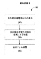
まず図8を参照すると、多孔質の非導電性の材料または障壁に基づくガス透過性電極または通気性電極の例示的な製造方法80が示されている。最初に、工程82では、多孔質の非導電性の材料または障壁、例えば多孔質ポリマー材料は、金属層との結合の向上を促進するため、重合、例えばプラズマ重合を用いて処理される。工程84では、重合した多孔質非導電性の材料または障壁は、金属、他の多くの金属も用いることができるが、例えば金で被覆、または少なくとも一部が被覆される。工程86では、1種または複数種の触媒が、例えばさらなる適用または被膜として適用される。一例では、少なくとも一部に、さらなる層または被膜として適用される白金でもよい。
Polymer Material Processing and Coating Referring first to FIG. 8, an
より具体的な例では、ポリテトラフルオロエチレン(PTFE)材料(ゴアテックス(登録商標))はゴア社から入手し、マイテックス(登録商標)(10μm)はミリポアから入手した。Auマイラ(2.5Ω/□)はCPフィルム社から購入した。無水マレイン酸はシグマ−アルドリッチから入手した。Pt被覆の前に行う、ゴアテックス(登録商標)、マイテックス(登録商標)、ポリエチレン(PE)およびポリプロピレン(PP)材料の作製は、サイエンス 2008;321:671−4の題名が「気相重合PEDOT電極上での酸素の高速還元」である、Winther−Jensenらの以前の研究と同様である。 In a more specific example, polytetrafluoroethylene (PTFE) material (Gore-Tex®) was obtained from Gore and Mytex® (10 μm) was obtained from Millipore. Au Mylar (2.5Ω / □) was purchased from CP Film. Maleic anhydride was obtained from Sigma-Aldrich. Fabrication of Gore-Tex®, Mytex®, polyethylene (PE) and polypropylene (PP) materials prior to Pt coating is under the title “Gas Phase Polymerization”, Science 2008; 321: 671-4 Similar to previous work by Winther-Jensen et al., “Fast reduction of oxygen on PEDOT electrodes”.
次に適用される金導電性層に強く結合させるために、プラズマ重合を用いて膜の疎水性表面に無水マレイン酸をグラフトした。金がプラズマ処理された膜の上にスパッタされ、その厚さは、表面抵抗が、〜5Ω/□となるように最適化された。次に、金層の上に28〜30mA、60秒でPtをスパッタした。従来のGDEも比較のため検討したが、E−TEKからのアイオノマーフリー(VulcanXC−72上にLT−140EW−30%Pt、0.5mgcm−2)を入手し、そのまま用いた。SEM画像は、JEOL7100F電界放出銃走査型電子顕微鏡を用いて5kVで得た。 Next, maleic anhydride was grafted onto the hydrophobic surface of the membrane using plasma polymerization in order to bond strongly to the applied gold conductive layer. Gold was sputtered onto the plasma treated film and its thickness was optimized so that the surface resistance was ˜5Ω / □. Next, Pt was sputtered on the gold layer at 28 to 30 mA for 60 seconds. Conventional GDE was also examined for comparison, but ionomer-free (LT-140EW-30% Pt, 0.5 mgcm −2 on Vulcan XC-72) from E-TEK was obtained and used as it was. SEM images were obtained at 5 kV using a JEOL 7100F field emission gun scanning electron microscope.
多孔質PTFE(ゴアテックス(登録商標))材料に基づいて作製した多孔質電極を“多孔質電極(G)”(すなわち、Pt被覆Au/ゴアテックス(登録商標))と呼ぶ。多孔質PTFE(マイテックス(登録商標))材料に基づく電極は、“多孔質電極(M)”(すなわち、Pt被覆Au/マイテックス(登録商標))と呼ぶ。 A porous electrode made on the basis of a porous PTFE (Goretex®) material is referred to as “porous electrode (G)” (ie, Pt-coated Au / Goretex®). Electrodes based on porous PTFE (Mitex®) material are referred to as “porous electrode (M)” (ie, Pt-coated Au / Mitex®).
多孔質材料の他の形態、例えば、フィブリルにより相互接続された節(node)を有する微細構造を有する、ポリテトラフルオロエチレン(PTFE)、ポリエチレン(PE)またはポリプロピレン(PP)等のポリマーの他の多孔質形態に基づくものを用いることもできることが理解されるべきである。 Other forms of porous material, for example other polymers such as polytetrafluoroethylene (PTFE), polyethylene (PE) or polypropylene (PP) having a microstructure with nodes interconnected by fibrils It should be understood that those based on porous morphology can also be used.
電極とセル組立
従来のラミネーターを用いて、作製したガス透過性電極または通気性電極を金のストリップで挟んだ。ラミネートの0.7cm2の窓は、両面粘着テープで試験セルに取り付けられ時に、作製した電極のPt被覆面に電解質が接触すること、およびガスが隣接室と通気できることを可能とする(図1a,1b,1c)。
Electrode and cell assembly Using a conventional laminator, the produced gas permeable or breathable electrode was sandwiched between gold strips. The 0.7 cm 2 window in the laminate allows the electrolyte to contact the Pt-coated surface of the fabricated electrode and allow gas to vent to the adjacent chamber when attached to the test cell with double-sided adhesive tape (FIG. 1a). , 1b, 1c).
図1aは、参照電極1、少なくとも一部が多孔質であるアノード3、カソード4、およびガス収集室7(すなわち、半通気セル)を含む、例示電解セル10を示す。電解質6は、電解質11を収容する。ガス透過性電極2はアノード3の一部であり、多孔質の材料または障壁を含んでいる。ガス透過性電極2はラミネート9の窓を介して電解質を接触している。動作時のセルでは、酸素ガスおよび/または水素ガスは、例えばガス輸送用の通路または管を用いて、電極またはセルから離れるように輸送される。
FIG. 1 a shows an
図1bは、図1aの半通気性セル10における、ガス(O2)とイオン(H+)の動きを模式的に示している。アノード3とカソード4の間に電位を設定する。酸素ガスは、実質的に気泡を形成することなく、生じまたはガス収集室7へと通過することが示されている。一方、ガス気泡、この例では水素ガス気泡は、電解質11中、カソード4で生じることが示されている。酸素プローブ5のマイクロ酸素電極の相対位置が示されている。
FIG. 1b schematically shows the movement of gas (O 2 ) and ions (H + ) in the
図1cは、例示の全通気性セル14におけるガスとイオンの動きを示している。この例では、カソード15は、ガス透過性の材料または障壁で少なくとも一部が形成された多孔質も含んでいる。水素ガスは、実質的に気泡を形成することなく、生じまたは第2のガス収集室16へと通過することが示されている。
FIG. 1 c shows the gas and ion movements in the exemplary fully breathable cell 14. In this example, the
実験装置及びガス測定
0.05MでpH4のナトリウムp−トルエンスルホン酸(シグマアルドリッチから)を、電解質11として用いた。30mlの電解質11を試験セル10中に用い、電解質10の上に30mlのガス空間を設けた。飽和カラメル参照電極(SCE)1およびカーボンロッドまたはPt対極4を用いて3電極セルを組み立てた。マルチチャンネルポテンショスタット(プリンストンアプライドリサーチのVMP2)を定電流電解に用いた。電極間の距離は1.5cmであり、全ての作用電極の動作時の電位は、典型的には〜2−2.4Vvs.SCEであった。
Experimental equipment and gas measurement
Sodium p-toluenesulfonic acid (from Sigma-Aldrich) at 0.05 M and pH 4 was used as electrolyte 11. 30 ml of the electrolyte 11 was used in the
マイクロ酸素電極5はeDAQから購入し、電解反応からのO2発生をモニターするのに用いた。空気中の21%O2と、純窒素ガスの0%O2で較正した。較正時の傾斜は、10.3mVが1%O2に相当する。H2量は、ガスクロマトグラフィー(SRI310C、MS−5Aカラム、TCD、Arキャリア)を用いて測定した。 The micro oxygen electrode 5 was purchased from eDAQ and used to monitor O 2 generation from the electrolytic reaction. Calibrated with 21% O 2 in air and 0% O 2 of pure nitrogen gas. As for the inclination at the time of calibration, 10.3 mV corresponds to 1% O 2 . The amount of H 2 was measured using gas chromatography (SRI310C, MS-5A column, TCD, Ar carrier).
結果
図1aおよび1bに示すように試験セル10を組み立てた。様々な他の応用が可能であるが、まず、実験は水の酸化(WO)に焦点を当てた。Pt被覆の多孔質の材料または障壁をアノード3の一部として用い、多孔質電極2の裏面側のガス収集室7(60ml)に配置したマイクロ酸素電極5を用いて遊離のO2をモニターした(図1a)。
Results A
10mAの電流をセルに通電してから数秒後、対極4(カーボンロッド)上に気泡が形成され始めた。アノード3上では、多孔質電極(G)21を用いた時は、作用領域には気泡は認められなかった。このことは、O2の大部分が、電極2の後部室7へ逃げることができたことを示唆している。別の材料を用いた場合、作用領域でいくらかの気泡の形成が認められた。後部室7のO2含有量は、多孔質電極(G)21と多孔質電極(M)22の場合、電解時に徐々に増加したが、GDE23では変化がなく(図2)、後者ではO2が生成していないことを示唆している。多孔質電極(G)からのO2発生速度が最も大きく、これは、多孔質電極(G)が、水酸化反応からガス状O2を放出させるのに、最も効率的であることを示している。 A few seconds after the current of 10 mA was passed through the cell, bubbles started to form on the counter electrode 4 (carbon rod). On the anode 3, when the porous electrode (G) 21 was used, no bubbles were observed in the action region. This suggests that most of the O 2 was able to escape to the rear chamber 7 of the electrode 2. When another material was used, some bubble formation was observed in the working area. O 2 content of the rear chamber 7, when the porous electrode (G) 21 and the porous electrode (M) 22, was gradually increased during the electrolysis, no change in GDE23 (Figure 2), in the latter O 2 Suggests that it is not generated. The rate of O 2 evolution from the porous electrode (G) is the highest, indicating that the porous electrode (G) is most efficient at releasing gaseous O 2 from the hydroxylation reaction. Yes.
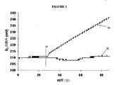
多孔質電極(G)を用いた水分解時に、前室6内で、電解質11の上部空間中のO2発生をモニターすることでさらなる検討を行った。結果(図3)は、電解質11の上では測定可能なO2の増加は認められず、後室7の中へ非常に高い効率でO2を除去できることを示している。これらの実験のファラデー効率は、90±3%であった。 Further investigation was performed by monitoring the O 2 generation in the upper space of the electrolyte 11 in the front chamber 6 during water splitting using the porous electrode (G). The results (FIG. 3) show that there is no measurable increase in O 2 on the electrolyte 11 and that O 2 can be removed into the back chamber 7 with very high efficiency. The Faraday efficiency of these experiments was 90 ± 3%.
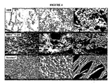
各電極または各材料の「通気」性能を理解するために、図4に示すように走査型電子顕微鏡観察を行った。Ptナノ粒子が材料表面に十分に分散していた。GDEの画像は、65〜100nmのPtナノ粒子の密な充填構造を示していた。材料上のスパッタされたPtナノ粒子の寸法は、30〜40nmの範囲であった。多孔質電極(M)の画像は、空孔寸法と分布に整合性がないことを示しているが、多孔質電極(G)の画像は整合性のある分布を持った微細な空孔寸法(〜1×10μm)を有していることを示している。多孔質電極(G)の構造は、水分解実験で多孔質電極(G)について観察される高性能に寄与していると考えられる。 In order to understand the “venting” performance of each electrode or each material, scanning electron microscope observation was performed as shown in FIG. Pt nanoparticles were sufficiently dispersed on the material surface. GDE images showed a dense packing structure of 65-100 nm Pt nanoparticles. The dimensions of the sputtered Pt nanoparticles on the material ranged from 30-40 nm. The image of the porous electrode (M) shows that the pore size and distribution are not consistent, but the image of the porous electrode (G) is a fine pore size (with consistent distribution) ( ˜1 × 10 μm). The structure of the porous electrode (G) is considered to contribute to the high performance observed for the porous electrode (G) in water splitting experiments.
比較実験として、電解質11の上に配置された酸素プローブ5を備えた単一室装置のアノードとして、Pt被覆Auマイラからなる非多孔質基材を用いた。この実験で製造されたO2は、2室装置中で多孔質電極(G)(1.35μmol/分)を用いた時よりも、非常に少なかった(0.48μmol/分)。この比較実験のファラデー効率は31%に過ぎなかった。これは、非多孔質電極を用いた時、セパレータがないこのセル構造中に存在する、電極間での酸素のやり取り(shuttling)の程度を示す。 As a comparative experiment, a non-porous substrate made of Pt-coated Au mylar was used as an anode of a single chamber device provided with an oxygen probe 5 disposed on an electrolyte 11. The O 2 produced in this experiment was much less (0.48 μmol / min) than when the porous electrode (G) (1.35 μmol / min) was used in the two-chamber apparatus. The Faraday efficiency of this comparative experiment was only 31%. This indicates the degree of oxygen shuttling between the electrodes present in this cell structure without separators when using non-porous electrodes.
別の実験では、Pt被覆Auマイラをアノードとして用い、多孔質電極(G)をカソードとして、すなわちH2発生電極として用いた。カソード上では、H2気泡の形成は認められなかった。この実験のO2発生のファラデー効率は61%であった。多孔質電極(G)をアノード3とカソード15の両方に用いた場合、セル14から両方のガスが除去され、ファラデー効率は92%に増加した。この実験で検出されたH2は、測定誤差の範囲内(±7%)で、2:1の化学量論比に近いことが見出された。これは、最適化されたセルとガス流の構成では、これらのセルでセパレータの使用を回避することが実用的であることを示唆している。
In another experiment, Pt-coated Au mylar was used as the anode, and the porous electrode (G) was used as the cathode, that is, as the H 2 generating electrode. On the cathode, the formation of H 2 bubbles was not observed. The Faraday efficiency of O 2 generation in this experiment was 61%. When the porous electrode (G) was used for both anode 3 and
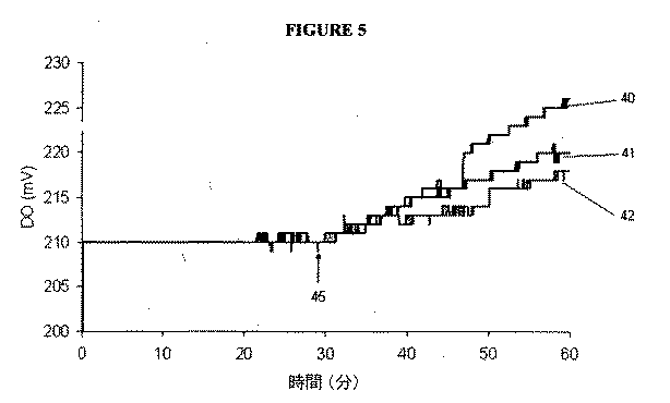
試験した3種の材料の中では、当初、ゴアテックス(登録商標)が最も優れていることが見出されたが、使用可能な、異なる疎水性と様々な空孔寸法および形状を有する他の材料が確かに存在する。これらの多くの可能性について、追加の実験で試験を行った。ポリエチレン(PE、セルガード880(0.1×1μ 空孔寸法))40、ポリプロピレン(PP)メッシュ(5μ空孔寸法)41およびPP不織布(5μ空孔寸法)42を上記と同様の方法で試験した(図5参照)。セルガード880は、装置の後室上で測定される酸素の増加からわかるようにゴアテックス(登録商標)と同様の優れた特性を有し、82%のファラデー効率に相当する。その2つのPP材料は、効率が低いが(それぞれ、51%と41%)、この材料を多孔質の材料または障壁構造に用いることができることを明らかに示している。 Of the three materials tested, Gore-Tex® was initially found to be the best, but other types with different hydrophobicity and various pore sizes and shapes that can be used. The material certainly exists. Many of these possibilities were tested in additional experiments. Polyethylene (PE, Celgard 880 (0.1 × 1μ pore size)) 40, polypropylene (PP) mesh (5μ pore size) 41 and PP nonwoven fabric (5μ pore size) 42 were tested in the same manner as described above. (See FIG. 5). Celgard 880 has excellent properties similar to Gore-Tex®, as can be seen from the increase in oxygen measured on the back chamber of the device, corresponding to a Faraday efficiency of 82%. The two PP materials are less efficient (51% and 41%, respectively), but clearly show that this material can be used for porous materials or barrier structures.
Ti/Au/ゴアテックス上のCdSの安定性試験およびTi/Au/ゴアテックスを用いたベースライン試験
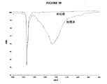
別の試験では、Au被覆ゴアテックス(登録商標)に、Tiを被覆して電極を形成した。電極の1つをさらにCdSで被覆した。CdS/Ti/Au/ゴアテックス電極およびTi/Au/ゴアテックス(0.5cm2)電極を積層し、2つのプラスチックボトルの間に挟んだ。前室6をpH6.5の0.05M NaPTSの30mlで満たした。酸素センサ5をガス後室7に配置した。DOプローブに直接光が当たるのを防ぐために室7を覆うために黒色布を用いた。試料に光を照射するためにアサヒランプを用いた。以下の手順の後、各データ点を収集した:N2ガスを用いて約15分間またはベースラインが安定するまで電解質をパージし、同時に後室にO2をフラッシュし、N2を除去した後直ぐに(および穴を封止した)試料に光を7分間照射し、さらに光を5分間照射しながらO2を除去した(および穴を封止した)。このプロセスを39回繰り返した。増加したO2をモニターし、典型的なグラフを図6に示す。
Stability test of CdS on Ti / Au / Goretex and baseline test using Ti / Au / Goretex In another test, Au coated Goretex® was coated with Ti to form an electrode . One of the electrodes was further coated with CdS. A CdS / Ti / Au / Goretex electrode and a Ti / Au / Goretex (0.5 cm 2 ) electrode were laminated and sandwiched between two plastic bottles. Anterior chamber 6 was filled with 30 ml of 0.05 M NaPTS at pH 6.5. An oxygen sensor 5 was disposed in the gas rear chamber 7. A black cloth was used to cover the chamber 7 to prevent direct exposure of the DO probe. An Asahi lamp was used to irradiate the sample with light. After the following steps, we were collected each data point: N 2 for about 15 minutes using a gas or baseline purges the electrolyte to stabilize, flush the O 2 simultaneously posterior chamber, after removal of the N 2 Immediately (and the hole was sealed) the sample was irradiated with light for 7 minutes, and O 2 was removed (and the hole was sealed) while further irradiating with light for 5 minutes. This process was repeated 39 times. The increased O 2 was monitored and a typical graph is shown in FIG.
そのデータを、露光時間に対するO2の増加割合(典型的には12分間の露光によるO2の読みの増加)としてプロットした(図7)。図7からわかるように、CdS/Ti/Au/ゴアテックス電極60からのO2の発生速度は、Ti/Au/ゴアテックス電極61のベースラインからよりも高く、8時間を超えても安定である。この結果を、光/酸素発生下でCdSが数分で通常劣化することと比較すべきである。
The data was plotted as the percentage increase in O 2 with respect to exposure time (typically the increase in O 2 reading with 12 minutes exposure) (FIG. 7). As can be seen from FIG. 7, the generation rate of O 2 from the CdS / Ti / Au /
ポリ酸とプラズマ重合を用いる表面処理は、触媒と膜との間に良好な結合を確保するための重要なステップである。それは、触媒を疎水性膜の上に堆積させるための道を開くものである。PEM電解装置では用途が限定された非貴金属および金属酸化物触媒をこの技術と融合する可能性が、簡単でコスト効率のよい水分解装置へとつながるであろう。その多くが酸素気泡の存在に敏感である光活性電極触媒の寿命を向上させるために、この方法を用いることもできる。 Surface treatment using polyacid and plasma polymerization is an important step to ensure a good bond between the catalyst and the membrane. It opens the way for the catalyst to be deposited on the hydrophobic membrane. The possibility of fusing non-precious metal and metal oxide catalysts, which have limited use in PEM electrolysers, with this technology would lead to a simple and cost effective water splitting device. This method can also be used to improve the lifetime of photoactive electrocatalysts, many of which are sensitive to the presence of oxygen bubbles.
実施例II 多孔性導電性材料に基づく電極
以下の実施例は、特定の実施形態についてより詳細な説明を提供するものである。実施例は単なる例示であり、本発明の範囲を限定するものではない。
Example II Electrode Based on Porous Conductive Material The following example provides a more detailed description of a particular embodiment. The examples are merely illustrative and are not intended to limit the scope of the present invention.
製造されたガスが電極を通って外へ拡散できる電極を形成するために、導電性材料で被覆した、多孔質で疎水性のポリマー材料または障壁について説明したこれまでの例では、気泡の形成を防止できるだけでなく、ガスを分離できる利点があり、それにより、さらなる反応または電極の腐食を防止できる。これらの改良された電極構造は、ガスを分離し、気泡の形成を防止するが、それらは、比較的高い抵抗を有している。比較的高い抵抗は、通気性電極の適用された金属層に関連し、電圧損失をもたらす。その結果、大規模な用途に用いるには、大型セルは高価である。さらに、高抵抗は、電極の加熱に関係し、局所的なホットスポット形成が起こる場合があり、それは蒸気形成を引き起こし、そして最終的にはセルの電極または他の部材の一部を燃焼させ、効率を低下させ、メインテナンスの必要性を増加させる。 In the previous examples describing porous and hydrophobic polymer materials or barriers coated with a conductive material to form an electrode through which the gas produced can diffuse out through the electrode, Not only can it be prevented, it has the advantage of being able to separate gases, thereby preventing further reactions or electrode corrosion. Although these improved electrode structures separate gases and prevent bubble formation, they have a relatively high resistance. The relatively high resistance is associated with the applied metal layer of the breathable electrode and results in voltage loss. As a result, large cells are expensive for use in large scale applications. In addition, the high resistance is related to the heating of the electrode, and local hot spot formation may occur, which causes vapor formation and eventually burns part of the cell's electrode or other member, Reduce efficiency and increase the need for maintenance.
別の例では、ガス透過性電極または通気性電極の製造方法が提供され、該製造方法は、多孔質またはガス透過性で導電性の材料または障壁を用意する工程と、該材料または該障壁の第1の面に疎水性層または疎水性被膜を適用または組み合わせる工程を含む。別の例では、多孔質またはガス透過性で導電性の材料または障壁は、導電性の材料または構造を含み、例えば、炭素繊維、グラフェンまたはカーボンナノチューブ等の導電性カーボン材料を含みまたはからなり、あるいはNi、Ti、Cr、Cu、Au、またはAg等の金属を含みまたはからなる。適切な材料または障壁は、種々の空孔寸法および空孔形状を有することができる。異なる導電性の材料または構造の組合せ、あるいは非導電性材料または構造と一体形成されたものを用いることができる。別の例では、多孔質またはガス透過性で導電性の材料自体または障壁自体が疎水性であってもよい。 In another example, a method of manufacturing a gas permeable electrode or a gas permeable electrode is provided, the method including providing a porous or gas permeable conductive material or barrier; and Applying or combining a hydrophobic layer or hydrophobic coating on the first surface. In another example, the porous or gas permeable conductive material or barrier comprises a conductive material or structure, for example comprising or consisting of a conductive carbon material such as carbon fiber, graphene or carbon nanotubes, Alternatively, it includes or consists of a metal such as Ni, Ti, Cr, Cu, Au, or Ag. Suitable materials or barriers can have various pore sizes and pore shapes. A combination of different conductive materials or structures, or a non-conductive material or structure integrally formed can be used. In another example, the porous or gas permeable conductive material itself or the barrier itself may be hydrophobic.
疎水性でポリマー系の材料または障壁に対して導電性層が適用される、前述の実施例(実施例Iセクション)とは異なり、このセクションの実施例では(実施例IIセクション)、まず、本質的に低抵抗の金属またはカーボン等の多孔質で導電性の材料または障壁が用意され、該導電性の材料または障壁の1つの面に疎水性の層または被膜を関連づけるまたは適用する。理論に束縛されるものではないが、疎水性の層または被膜により発現される機能の1つは、該材料または該障壁を介して電解質が漏出することを防止することであると思われる。 Unlike the previous example (Example I section) where the conductive layer is applied to a hydrophobic polymer-based material or barrier, the example in this section (Example II section) begins with the essentials A porous, electrically conductive material or barrier such as a low resistance metal or carbon is provided, and a hydrophobic layer or coating is associated with or applied to one side of the electrically conductive material or barrier. Without being bound by theory, it appears that one of the functions exhibited by a hydrophobic layer or coating is to prevent electrolyte from leaking through the material or the barrier.
本セクション(実施例IIセクション)の実施例に基づいて製造されたガス透過性電極または通気性電極の場合の2Vと比較すると、同じ電流で、前述の実施例(実施例Iセクション)のガス透過性電極または通気性電極は4Vもの動作電圧を有している。同時に、前述の電極は、通常、所定電流で、約10Ω/m2の抵抗を有しているが、本セクションの実施例に基づいて製造されたガス透過性電極または通気性電極は、同じ電流で、<1Ω/m2の抵抗を有している。電極の電圧および抵抗が低いほど、電極が加熱されなくなるので、これは有利な点である。 The gas permeation of the previous example (Example I section) at the same current when compared to 2 V for gas permeable or breathable electrodes made according to the examples of this section (Example II section) The conductive or breathable electrode has an operating voltage of 4V. At the same time, the electrodes described above typically have a resistance of about 10 Ω / m 2 at a given current, but gas permeable or breathable electrodes manufactured according to the examples in this section will have the same current. And has a resistance of <1Ω / m 2 . This is an advantage because the lower the voltage and resistance of the electrode, the less heated the electrode.
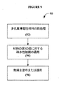
図9は、多孔質で導電性の材料または障壁に基づく、ガス透過性で、多孔質または通気性の電極の製造方法90を示す。任意の工程92では、ガス透過性または多孔質で導電性の材料または障壁の前処理が行われ、例えば、疎水性の層または被膜を関連付けるまたは適用する前に酸化物が除去され、あるいは不純物の除去、または導電性表面の洗浄または処理がなされる。工程94では、疎水性の層または被膜が、ガス透過性または多孔質で導電性の材料または障壁に対して少なくとも部分的に適用または組み合わせる。工程96では、1つの触媒または複数の触媒が、ガス透過性または多孔質で導電性の材料または障壁の第2の面、すなわち対向し、露出する導電性または金属の電極表面に対して、少なくとも部分的に塗布または適用される。
FIG. 9 illustrates a
別の例では以下の工程を含むガス透過性電極または通気性電極の製造方法が提供され、該製造方法は、ガス透過性または多孔質の導電性材料の多孔質ガスを用意する工程と、例えば酸化物を除去するために、必要に応じて、ガス透過性または多孔質の導電性材料を前処理する工程と、ガス透過性または多孔質の導電性材料の第1の面に疎水性の層または被膜を少なくとも部分的に組み合わせるまたは適用する工程と、およびガス透過性または多孔質の導電性材料の第2の面の少なくとも一部に触媒を適用する工程を含む。ガス透過性または多孔質の導電性材料の第2の面の少なくとも一部に触媒を適用する工程は、ガス透過性または多孔質の導電性材料の第1の面に疎水性の被膜を適用する工程の前、後または同時に行うことができる。 In another example, a method for producing a gas permeable electrode or a gas permeable electrode including the following steps is provided, the method comprising preparing a porous gas of a gas permeable or porous conductive material, for example, Optionally, pretreating a gas permeable or porous conductive material to remove oxide, and a hydrophobic layer on the first side of the gas permeable or porous conductive material Or at least partially combining or applying the coating and applying a catalyst to at least a portion of the second surface of the gas permeable or porous conductive material. The step of applying a catalyst to at least a portion of the second side of the gas permeable or porous conductive material applies a hydrophobic coating to the first side of the gas permeable or porous conductive material. It can be done before, after or simultaneously with the process.
図11は、電解質118と接触している例示の多孔質またはガス透過性または通気性の電極110の断面図を示している。電極110は、ガス透過性または多孔質で導電性の層、障壁または材料112を含む。多孔質で導電性の層、障壁または材料112の第1の面は疎水性の層、障壁または材料114であり、例えば疎水性ポリマー材料である。多孔質で導電性の層、障壁または材料112の第2の面および/または内部は、1種または複数種の触媒116である。1種または複数種の触媒は、通常、多孔質で導電性の層、障壁または材料112の空孔または空間と同一の広がりを有し、および/またはそれらの内部にある、隣接層として設けることができる。限定されない具体例として、多孔質で導電性の層、障壁または材料112がニッケルまたは銅であり、疎水性の層、障壁または材料114がポリパーフルオロ(メチルデカリン)である。
FIG. 11 shows a cross-sectional view of an exemplary porous or gas permeable or
多孔質導電性材料
ガス透過性または多孔質で導電性の材料または障壁は、好ましくは、多孔質カーボン材料または多孔質金属材料から選定または選択される。好ましくは、多孔質導電性材料は、抵抗が3Ω/m2未満、より好ましくは1Ω/m2未満である。多孔質導電性材料は、好ましくは、空孔寸法が、50μm未満、より好ましくは20μm未満または10μm未満である。金属等の広範囲の導電性材料が、多孔質導電性材料としての使用に適しているが、特に好ましいものは、Ni、TiおよびCr等の公知の‘安定’酸化物形成金属と、Cu、Au、Ag等の‘貴’金属である。
Porous conductive material The gas permeable or porous conductive material or barrier is preferably selected or selected from a porous carbon material or a porous metal material. Preferably, the porous conductive material is less than resistance 3 [Omega] / m 2, more preferably less than 1Ω / m 2. The porous conductive material preferably has a pore size of less than 50 μm, more preferably less than 20 μm or less than 10 μm. A wide range of conductive materials such as metals are suitable for use as porous conductive materials, but particularly preferred are known 'stable' oxide-forming metals such as Ni, Ti and Cr, and Cu, Au , 'Noble' metals such as Ag.
一例では、多孔質導電性材料は、不織布炭素繊維を含み、広い範囲の空孔寸法と厚さを有するそれら材料が商業的に入手可能である。炭素繊維織物は適しているかもしれないが、現在商業的に入手可能な炭素繊維織物は一般的に厚すぎるかもしれない。カーボンナノチューブフェルトは、空孔サイズがあまり小さくなければ、適しているかもしれない。 In one example, the porous conductive materials include non-woven carbon fibers, and those materials having a wide range of pore sizes and thickness are commercially available. While carbon fiber fabrics may be suitable, currently commercially available carbon fiber fabrics may generally be too thick. Carbon nanotube felt may be suitable if the pore size is not too small.
別の例では、多孔質導電性材料は、金属、あるいはメッシュ織物、不織布メッシュ、グリッド、ネット、ラティス、ウェブまたは他の多孔質構造を含む金属の組合せである。好ましい例では、多孔質導電性材料は、織物または不織布の銅、織物または不織布の銅被覆繊維、織物または不織布のニッケル、または織物または不織布のニッケル被覆繊維から構成されている。 In another example, the porous conductive material is a metal or a combination of metals including mesh fabrics, nonwoven meshes, grids, nets, lattices, webs or other porous structures. In a preferred example, the porous conductive material is composed of woven or non-woven copper, woven or non-woven copper-coated fibers, woven or non-woven nickel, or woven or non-woven nickel-coated fibers.
材料は、支持されている導電性材料(カーボンまたは金属等)を含んでもよい。例えば、繊維、ストランド、織物または他の基材の上に、導電性材料を塗布、適用、スパッタリングまたは積層することにより形成してもよく、次いで織物にして多孔質導電性材料を形成する。 The material may include a supported conductive material (such as carbon or metal). For example, it may be formed by applying, applying, sputtering, or laminating a conductive material on a fiber, strand, fabric or other substrate, and then forming the porous conductive material into a fabric.
多孔質導電性材料の前処理
疎水性の層または被膜を追加する前に、例えば、酸化物の層または粒子を除去するために、多孔質導電性材料を前処理することが好ましい。具体的には、酸化物の不安定な層は、特にもし導電性材料が金属またはカーボンの場合、導電性材料の表面に形成され易い。また、電極に電位が印加されていると、該表面と疎水性層の間に酸化物層が成長し易い。これは、通常、疎水性の低下を引き起こし、疎水性の層または被膜が金属から剥離する原因となる。
Pretreatment of the porous conductive material It is preferred to pretreat the porous conductive material before adding the hydrophobic layer or coating, for example to remove oxide layers or particles. Specifically, the unstable oxide layer is likely to be formed on the surface of the conductive material, particularly if the conductive material is a metal or carbon. Further, when a potential is applied to the electrode, an oxide layer easily grows between the surface and the hydrophobic layer. This usually causes a decrease in hydrophobicity and causes the hydrophobic layer or coating to peel from the metal.
したがって、金属またはカーボン等の導電性表面と疎水性の層または被膜との間の直接結合を確保または向上させるため、導電性材料の表面の酸化物を除去するために、表面還元を行うことが望ましい。前処理は、水素プラズマまたは従来の化学還元前処理等の公知の技術を用いて行うことができる。プラズマ技術が特に好ましく、それは、疎水性の層または被膜を適用するまで、材料の表面を容易に酸素が存在しない状態にしておくことができるからでる。 Therefore, surface reduction can be performed to remove oxides on the surface of the conductive material in order to ensure or improve the direct bond between the conductive surface such as metal or carbon and the hydrophobic layer or coating. desirable. The pretreatment can be performed using a known technique such as hydrogen plasma or conventional chemical reduction pretreatment. Plasma technology is particularly preferred because the surface of the material can be easily left free of oxygen until a hydrophobic layer or coating is applied.
疎水性の層または被膜
任意の利用可能な方法、例えば、プラズマ重合、噴霧法または溶媒系塗布方法等を用いて、多孔質導電性材料の少なくとも一部に疎水性の層または被膜を適用または組み合わせることができる。多孔質導電性材料を被覆するのに適したいくつかの例示的方法は、国際特許公開番号WO2001/085635(Winther−Jensen)に開示されている。
Hydrophobic layer or coating Apply or combine the hydrophobic layer or coating to at least a portion of the porous conductive material using any available method, such as plasma polymerization, spraying or solvent-based coating methods, etc. be able to. Some exemplary methods suitable for coating porous conductive materials are disclosed in International Patent Publication No. WO 2001/085635 (Winther-Jensen).
好ましい方法では、疎水性の層または被膜は、プラズマ重合により適用される。この適用方法は、多孔質導電性材料の中へのポリマーの浸透を細かく制御できるように‘調整’可能であるので好ましい。その結果、プラズマ重合を適用することで所定材料を最適化することができる。例えばフッ素化前駆体に基づいて、広範囲の疎水性被膜を用いることができる。 In a preferred method, the hydrophobic layer or coating is applied by plasma polymerization. This method of application is preferred because it can be 'tuned' so that the penetration of the polymer into the porous conductive material can be finely controlled. As a result, the predetermined material can be optimized by applying plasma polymerization. For example, a wide range of hydrophobic coatings can be used based on fluorinated precursors.
同様に、噴霧塗布に関し、フッ素化エチレンプロピレン(FEP)等のテフロン(登録商標)系の多くの溶媒可溶性のポリマーが使用可能である。 Similarly, a number of Teflon-based solvent soluble polymers such as fluorinated ethylene propylene (FEP) can be used for spray application.
しかし、用いる適用技術に関し、電極の反対側の金属面を分離または覆うことがないように、多孔質導電性材料への疎水性の層または被膜の浸透が細かく制御されることが重要であり、すなわち、疎水性の層または被膜は、多孔質導電性材料の中への経路の一部、またはおそらくすべてではない経路のみに浸透または延在するだけでよく、および電極の反対面を覆うことのないように、または重なることのないようにすべきである。 However, for the application technique used, it is important that the penetration of the hydrophobic layer or coating into the porous conductive material is finely controlled so as not to separate or cover the metal surface on the opposite side of the electrode, That is, the hydrophobic layer or coating only needs to penetrate or extend only a portion of the path into the porous conductive material, or perhaps not all, and cover the opposite side of the electrode. There should be no or no overlap.
疎水性の層または被膜は、ウンデカン等のC1〜C16アルカン等の炭化水素、C〜C16アルケン、C2〜C16アルキン、スチレン、スチレン系化合物の芳香族モノマー、ビニル系およびアクリレート系化合物のモノマー等の広い範囲の前駆体モノマーから作製することができる。フッ素化炭化水素前駆体が特に好ましいが、それは、使用時に材料からの電解質の漏れに対して優れた防止効果を有するからである。好ましい実施形態では、疎水性の層または被膜は、パーフルオロ(メチルデカリン)、1H,1H,2H−パーフルオロ−1−デセン、および他のフッ素化炭化水素から選択される前駆体から作製される。多くの他の適切なフッ素化炭化水素前駆体が当業者には明らかであろう。 Hydrophobic layers or coatings include hydrocarbons such as C1-C16 alkanes such as undecane, C-C16 alkenes, C2-C16 alkynes, styrene, aromatic monomers of styrenic compounds, monomers of vinyl and acrylate compounds, etc. It can be made from a wide range of precursor monomers. Fluorinated hydrocarbon precursors are particularly preferred because they have an excellent preventive effect on electrolyte leakage from the material during use. In a preferred embodiment, the hydrophobic layer or coating is made from a precursor selected from perfluoro (methyldecalin), 1H, 1H, 2H-perfluoro-1-decene, and other fluorinated hydrocarbons. . Many other suitable fluorinated hydrocarbon precursors will be apparent to those skilled in the art.
触媒
多孔質導電性材料は、反応触媒として作用することができる。あるいは、1種または複数種の触媒を、疎水性の層または被膜で既に覆われていない導電性材料の面の少なくとも一部に適用してもよい。触媒は、電極上で起こる反応に対して適切な公知の触媒から選択することができる。一般的に、例えば、白金、金、パラジウム等の貴金属を用いることができ、あるいはRuやIr等の公知の希土類元素およびそれらの錯体、Mn錯体、およびFe、NiOxおよびCo等の豊富金属の錯体を用いることができる。
Catalyst The porous conductive material can act as a reaction catalyst. Alternatively, one or more catalysts may be applied to at least a portion of the surface of the conductive material that is not already covered with a hydrophobic layer or coating. The catalyst can be selected from known catalysts suitable for the reaction taking place on the electrode. In general, for example, noble metals such as platinum, gold and palladium can be used, or known rare earth elements such as Ru and Ir and their complexes, Mn complexes, and abundant metals such as Fe, NiO x and Co. Complexes can be used.
安定性を向上させるため、それら金属酸化物錯体は、リン等の追加元素を含んでもよい。ポリ(3,4−エチレンジオキシチオフェン)やポリピロール等の導電性ポリマー、Co、Ni、Fe錯体およびMoSxを触媒として用いることもできる。触媒の選択は、電解液の温度、塩分およびpH等の動作条件に少なくとも部分的には依存するであろう。 In order to improve the stability, these metal oxide complexes may contain additional elements such as phosphorus. Conductive polymers such as poly (3,4-ethylenedioxythiophene) and polypyrrole, Co, Ni, Fe complex and MoS x can also be used as a catalyst. The choice of catalyst will depend at least in part on operating conditions such as electrolyte temperature, salinity and pH.
好ましい例では、通気性電極は、ポリ(パーフルオロ(メチルデカリン)−炭素繊維−PEDOT(ここで、PEDOTは、ポリ(3,4−エチレンジオキシチオフェン))、ポリ(パーフルオロ(メチルデカリン))−銅−白金、ポリ(パーフルオロ(メチルデカリン))−ニッケル、またはポリ(パーフルオロ(メチルデカリン))−ニッケル−白金から選択される疎水性被膜−導電性材料−触媒の組合せを含む。 In a preferred example, the breathable electrode is poly (perfluoro (methyldecalin) -carbon fiber-PEDOT (where PEDOT is poly (3,4-ethylenedioxythiophene)), poly (perfluoro (methyldecalin)). ) -Copper-platinum, poly (perfluoro (methyldecalin))-nickel, or poly (perfluoro (methyldecalin))-nickel-platinum, comprising a hydrophobic coating-conductive material-catalyst combination.
電極とセルアセンブリ
以下に示す多孔質導電性材料の範囲のより具体的な例を電解セル中で試験した。
材料1:燃料電池用の標準‘不織布’カーボンガス拡散材料(平均空孔寸法は25ミクロン、厚さは300ミクロン)
材料2:ニッケルワイヤーメッシュ、60ミクロンワイヤー/60ミクロン空孔、単層。
材料3:可撓性の織物に製織された銅被覆のナイロン11繊維。空孔寸法は約20ミクロン。
材料4:製織されたNi被覆織物(レアードテクノロジーズの#3055−213)。
材料5:Ni被覆不織布(レアードテクノロジーズの#3029−217)。
Electrode and Cell Assembly More specific examples of the range of porous conductive materials shown below were tested in an electrolytic cell.
Material 1: Standard 'nonwoven fabric' carbon gas diffusion material for fuel cells (average pore size is 25 microns, thickness is 300 microns)
Material 2: Nickel wire mesh, 60 micron wire / 60 micron pore, single layer.
Material 3: Copper-coated nylon 11 fiber woven into a flexible fabric. The pore size is about 20 microns.
Material 4: Woven Ni-coated fabric (Laird Technologies # 3055-213).
Material 5: Ni-coated nonwoven fabric (Laird Technologies # 3029-217).
最初の試験のため、多孔質導電性材料の一方の面が電解質に接触し、他方の面は周囲の空気の方を向くように、すべての多孔質導電性材料は、金のコネクターで簡単にラミネートされ、電気化学セルの中に別々に取り付けられた。該材料を作用電極として用い、0.1M H2SO4電解質中で、0.5V(V vs.SCE)の電位を印加した。電位が印加されると、該材料2〜5は、直ぐに空孔が濡れ、次いで電解質が漏れ出した。材料1は、電解質の漏れが検出されるまで、約30分間動作した。 For the first test, all porous conductive materials can be easily removed with a gold connector so that one side of the porous conductive material contacts the electrolyte and the other side faces the surrounding air. Laminated and mounted separately in an electrochemical cell. The material was used as a working electrode and a potential of 0.5 V (V vs. SCE) was applied in 0.1 MH 2 SO 4 electrolyte. When a potential was applied, the materials 2-5 immediately wetted the pores and then the electrolyte leaked out. Material 1 operated for about 30 minutes until electrolyte leakage was detected.
材料1〜5からなる第2の電極セットを作製し、多孔質導電性材料の一方の面のみがプラズマの方を向くように、プラズマ処理用ホルダーの上に取り付けた。試料を、国際特許公開番号WO2002/035895に記載されたタイプの2リッターのプラズマ室内に配置し、アルゴンを1.5ml/分の流量で流し、圧力を5Paまで低下させた。その後、10ml/分の流量で水素ガスを添加し、全圧を20Paまで増大させた。20mAの電力でプラズマ放電を開始し、多孔質導電性材料の表面を洗浄および還元するために、10分間継続した。 A second electrode set made of materials 1 to 5 was prepared and mounted on the plasma processing holder so that only one surface of the porous conductive material faced the plasma. The sample was placed in a 2 liter plasma chamber of the type described in International Patent Publication No. WO2002 / 035895, argon was flowed at a flow rate of 1.5 ml / min, and the pressure was reduced to 5 Pa. Thereafter, hydrogen gas was added at a flow rate of 10 ml / min to increase the total pressure to 20 Pa. A plasma discharge was started with a power of 20 mA and continued for 10 minutes to clean and reduce the surface of the porous conductive material.
この初期処理後、水素流を停止し、同時に、パーフルオロ(メチルデカリン)前駆体を流し始め、10mAのプラズマ電流で10Paの圧力に達するまで調整した。これらの重合条件を20分間維持し、次いで電力と前駆体流を停止し、室をアルゴンで数回フラッシュし、前駆体と励起種の残部を除去した。室を大気圧に戻してから、試料を室とホルダーから取り出した。プラズマ被膜の特性は、ATR−FAIRで分析し、その場合、同じバッチで電極として処理したポリエチレン材料を基材として用いた。 After this initial treatment, the hydrogen flow was stopped and at the same time the perfluoro (methyldecalin) precursor was started to flow until a pressure of 10 Pa was reached with a plasma current of 10 mA. These polymerization conditions were maintained for 20 minutes, then power and precursor flow were stopped, the chamber was flushed several times with argon to remove the remainder of the precursor and excited species. After returning the chamber to atmospheric pressure, the sample was removed from the chamber and holder. The properties of the plasma coating were analyzed by ATR-FAIR, in which case a polyethylene material treated as an electrode in the same batch was used as the substrate.
図10は、パーフルオロ(メチルデカリン)の重合の前と後の、FTIRの結果を示すが、処理された試料には、1150〜1250cm−1において特徴的なCF2およびCF3のシグナチャー(signatures)を明確に示している。水に対する接触角測定により多孔質導電性材料についてさらに検討したところ、それらはすべて後退接触角が150度を超えていた。 FIG. 10 shows the FTIR results before and after perfluoro (methyldecalin) polymerization, but the treated samples contain signatures of the CF 2 and CF 3 signatures at 1150-1250 cm −1 . ) Is clearly shown. Further investigation of the porous conductive materials by measuring the contact angle with water revealed that all of them had a receding contact angle exceeding 150 degrees.
プラズマ重合に曝されていない、多孔質導電性材料の面に触媒を適用した。標準的なスパッタリング方法および装置を用いて白金を適用した(25mAで30秒間)。次いで、試料を作用電極とし、各電極について、白金触媒被覆面が電解質に接触し、疎水性材料被覆面が空気の方を向くように、セル14と同様のタイプである、同じ電解セルの中に試料を取り付け、初期試験での条件と同じ条件で試験を行った。 The catalyst was applied to the side of the porous conductive material that was not exposed to plasma polymerization. Platinum was applied using standard sputtering methods and equipment (25 mA for 30 seconds). Next, in the same electrolytic cell, which is the same type as the cell 14, with the sample as the working electrode, and for each electrode, the platinum catalyst coated surface is in contact with the electrolyte and the hydrophobic material coated surface is facing the air. A sample was attached to the test piece, and the test was performed under the same conditions as in the initial test.
試験した材料に対応する5つの電極のそれぞれについての結果は以下の通りである。 The results for each of the five electrodes corresponding to the materials tested are as follows.
材料1電極:−0.5Vと電流約6mA/cm2の連続運転の10日後、漏れは検出されなかった。しかし、少量の水素気泡が検出され、追加の実験によれば、この特定の材料の気泡形成は約4mA/cm2を超える電流で開始されたことが明らかとなった。 Materials 1 electrode: -0.5 V and after 10 days of continuous operation of the current of about 6 mA / cm 2, no leaks were detected. However, a small amount of hydrogen bubbles was detected and additional experiments revealed that bubble formation for this particular material was initiated at a current greater than about 4 mA / cm 2 .
材料2電極:−0.5Vと電流約6.5mA/cm2の連続運転の5日後、電極の1つの角で漏れが検出された。気泡形成は観察されなかった。 Materials 2 electrode: after 5 days of continuous operation -0.5V and current of about 6.5 mA / cm 2, leakage in one corner of the electrodes is detected. Bubble formation was not observed.
材料3電極:−0.5Vと電流約6mA/cm2の連続運転の10日後、漏れは検出されなかった。気泡形成は観察されなかった。しかし、還元電位を停止すると、銅が速やかに酸性電解質中に溶解した。 Materials 3 electrodes: After 10 days of continuous operation -0.5V and current of about 6 mA / cm 2, no leaks were detected. Bubble formation was not observed. However, when the reduction potential was stopped, copper quickly dissolved in the acidic electrolyte.
材料4電極:−0.5Vと電流約6.5mA/cm2の連続運転の10日後、漏れは検出されなかった。気泡形成は観察されなかった。 Materials 4 electrode: -0.5 V and after 10 days of continuous operation of the current of about 6.5 mA / cm 2, no leaks were detected. Bubble formation was not observed.
材料5電極:漏れは、実験開始後ほぼすぐに観察された。理論に束縛されるものではないが、これは、不織布構造を形成した後に金属被膜が織物に適用されるという材料の性質によるものであると推定される。材料3と4からなる電極に関しては、それらが最終的な織物に製織される前にポリマー繊維に対して金属被膜が適用された。 Material 5 electrode: Leakage was observed almost immediately after the start of the experiment. Without being bound by theory, it is presumed that this is due to the nature of the material that the metal coating is applied to the fabric after forming the nonwoven structure. For electrodes consisting of materials 3 and 4, a metal coating was applied to the polymer fibers before they were woven into the final fabric.
本発明を、その特定の実施形態に関して説明したが、さらなる変形が可能であることが理解されるであろう。本願は、本発明のあらゆる変更、使用または付加を包含することを意図するものであり、それは、本発明の原理に従うものであり、かつ本発明の関係する技術における公知技術または慣用技術の範囲内にあり、かつ上述の本質的な特徴に適用できる本発明からの逸脱を含んでいる。 Although the invention has been described with reference to specific embodiments thereof, it will be understood that further modifications are possible. This application is intended to cover any modifications, uses, or additions of the invention, which are in accordance with the principles of the invention and are within the scope of known or common art in the technology to which the invention pertains. And includes deviations from the present invention applicable to the essential features described above.
実施例III さらなる用途例
以下の実施例は特定の実施形態についてのさらなる説明を提供する。実施例は単なる例示であり、本発明の範囲を限定するものではない。
Example III Further Application Examples The following examples provide further explanation of specific embodiments. The examples are merely illustrative and are not intended to limit the scope of the present invention.
実施例Iセクションで説明した、多孔質で非導電性の材料または障壁に基づくガス透過性電極または通気性電極は、様々な用途を有している。例えば、ガス透過性電極または通気性電極は、ガス合成セルに用いることができる。ガス透過性電極または通気性電極は、フロー−空気電池、金属−空気電池または可逆的な金属−空気電池等の電池に用いることができる。別の例では、ガス透過性電極または通気性電極は、可逆的ポリマー空気電池等の可逆的空気電極電池システムに用いることができる。別の例では、ガス透過性電極または通気性電極は、燃料電池に用いることができる。 Gas permeable or breathable electrodes based on porous, non-conductive materials or barriers as described in the Example I section have a variety of uses. For example, a gas permeable electrode or a gas permeable electrode can be used in a gas synthesis cell. Gas permeable or breathable electrodes can be used in batteries such as flow-air batteries, metal-air batteries or reversible metal-air batteries. In another example, a gas permeable electrode or a breathable electrode can be used in a reversible air electrode battery system, such as a reversible polymer air battery. In another example, gas permeable or breathable electrodes can be used in fuel cells.
特定の例では、ガス透過性電極または通気性電極は、以下の式に基づき電極上の硝酸塩を還元することにより、N2O(亜酸化窒素)を生成させるために用いることができる。
2NO2 −+6H++4e−⇒N2O+3H2O
In a particular example, a gas permeable or breathable electrode can be used to generate N 2 O (nitrous oxide) by reducing nitrate on the electrode based on the following formula:
2NO 2 − + 6H + + 4e − → N 2 O + 3H 2 O
電極は、その上に適用された活性触媒は、例えば、金被覆多孔質材料(実施例I説明した種類の)を有することができる。出願人は、通気性電極を通って外に拡散したN2Oからガスクロマトグラフィーで検出されたように、>70%の(ファラデー)効率を達成した。電流の残りは、NH2OHを生成させたが、それも商業的に有用な生成物である。そのプロセスは、pHに依存し、低pH(例えばpH4)ではより高い生成(電流で測定)を与えるが、N2O生成の選択性は低い。反応の開始は、約−0.05V vs.SCEであり、過電圧は僅かに約300mVである。これらの結果は、金属(この例では金)で被覆された疎水性材料に基づく通気性電極に対して得られた。 The electrode can have, for example, a gold-coated porous material (of the kind described in Example I), the active catalyst applied thereon. Applicants achieved (Faraday) efficiencies of> 70% as detected by gas chromatography from N 2 O diffused out through the breathable electrode. The remainder of the current produced NH 2 OH, which is also a commercially useful product. The process is pH dependent and gives higher production (measured by current) at low pH (eg pH 4), but the selectivity of N 2 O production is low. The start of the reaction is about -0.05 V vs. SCE, overvoltage is only about 300 mV. These results were obtained for a breathable electrode based on a hydrophobic material coated with a metal (gold in this example).
別の特定の例に関連して、アンモニアは年間1億3000万トンを超える量が世界で製造されている最も重要な化学品の1つである。NH3製造は、世界的に農業生産を維持するために不可欠である。アンモニア製造の主要な現在のプロセスはハーバー−ボッシュ法である。アンモニアの合成は、発熱反応であるが、230〜420kJ/molの高い活性化エネルギーを越えるためには、かなりのエネルギー投入が必要とされている。
窒素と水素の直接反応は、以下の反応に従う。
N2(g)+3H2(g)⇔2NH3(g) ΔH298=−92.2kJ/mol
In connection with another specific example, ammonia is one of the most important chemicals produced in the world in quantities exceeding 130 million tons per year. NH 3 production is essential for maintaining agricultural production worldwide. The main current process for ammonia production is the Haber-Bosch process. The synthesis of ammonia is an exothermic reaction, but considerable energy input is required to exceed the high activation energy of 230 to 420 kJ / mol.
The direct reaction between nitrogen and hydrogen follows the following reaction.
N 2 (g) + 3H 2 (g) ⇔2NH 3 (g) ΔH 298 = −92.2 kJ / mol
例示セルでは、実施例Iで説明した種類のガス透過性電極または通気性電極を用い、ハーバー−ボッシュ法を、アンモニア製造の効率的な電気化学プロセスで置き換えることができ、その場合、水素源は水である。 In an exemplary cell, a gas permeable or breathable electrode of the type described in Example I can be used to replace the Haber-Bosch process with an efficient electrochemical process for ammonia production, where the hydrogen source is It is water.
図12を参照すると、前述のカソード15を含むとともに、多孔質材料を含む、アンモニア製造用セル/装置120が記載されている。水の酸化はアノード122で起きることが示され、該アノードは標準的な形態のアノードまたはアノード3であり、前述の多孔質材料を含んでいる。
Referring to FIG. 12, an ammonia production cell /
環境条件下、カソード15でアンモニアを電気化学的に製造するための反応のプロトン源として、水の酸化反応を用いることができる。そのため、セル120は、H2を製造するのに必要なエネルギーを低減することでハーバー−ボッシュ法の課題を克服する。作用の向上または改善のために、触媒をカソード15に添加、または組み合わせることができる。これは、環境条件下での窒素の還元反応を促進することができる。
An oxidation reaction of water can be used as a proton source for a reaction for electrochemically producing ammonia at the
セル120の一般的な設計を、他のガス相の反応、例えば、三相界面と効率的な電解触媒が必要とされる該反応に用いることができる。
The general design of the
図13を参照すると、カソード15とアノード3を有し、その一方または両方が、前述の透過性または多孔質材料、および電解質132を含む、例示燃料電池130が記載されている。2つの化学反応が、アノード3/電解質132とカソード15/電解質132の界面で起きている。その2つの反応の最終結果は、燃料が消費され、様々な燃料を燃料電池130で用いることができる、ということである。典型的には、水または二酸化炭素が製造され、アノード3とカソード15の間で電流が作られ、それが電気装置134に電力を供給する。
Referring to FIG. 13, an
アノード3では、触媒が燃料、通常例えば水素を酸化し、燃料を、正に荷電したイオンや電子へと変換する。電解質132は、該電解質132を通ってイオンは通過できるが、電子は通過できないように設計された物質である。電子は、伝導経路を介して移動し、電気装置134への電流を作製する。イオンは電解質132を通ってカソード15に移動する。カソード15では、イオンは、第3の化学品、通常、例えば、酸素と反応し、水または二酸化炭素を生成する。
At the anode 3, the catalyst oxidizes the fuel, usually hydrogen, for example, and converts the fuel into positively charged ions and electrons. The
例示的実施形態の様々な態様、特にこれらおよび他の例示用途に関する態様が、以下に記載されている。 Various aspects of the exemplary embodiments, particularly those relating to these and other exemplary applications, are described below.
一例では、多孔質材料を含む少なくとも1つの電極を有する電解セルが提供され、該少なくとも1つの電極で製造されたガスが該多孔質材料を介してセルの外へ拡散する。 In one example, an electrolysis cell is provided having at least one electrode comprising a porous material, and a gas produced with the at least one electrode diffuses out of the cell through the porous material.
別の例では、動作時には、気泡を形成することなく、または実質的に気泡を形成することなく、少なくとも一つの電極でガスが製造される。 In another example, in operation, gas is produced with at least one electrode without forming bubbles or substantially without forming bubbles.
様々な例では、前記の少なくとも1つの電極で製造されたガスの90%を超える量が、多孔質材料を横切ってまたは通ってセルから除去され、前記の少なくとも1つの電極で製造されたガスの95%を超える量が、多孔質材料を横切ってまたは通ってセルから除去され、および/または前期の少なくとも1つの電極で製造されたガスの99%を超える量が、多孔質材料を横切ってまたは通ってセルから除去される。別の例では、多孔質材料は、電解質不透過性である。 In various examples, greater than 90% of the gas produced at the at least one electrode is removed from the cell across or through the porous material, and the amount of gas produced at the at least one electrode. More than 95% is removed from the cell across or through the porous material and / or more than 99% of the gas produced at the at least one electrode in the previous period is across the porous material or Removed from the cell. In another example, the porous material is electrolyte impermeable.
様々な他の例では、製造されたガスは平均直径が125μm未満の気泡を形成せず、製造されたガスは平均直径が100μm未満の気泡を形成せず、および/または製造されたガスは平均直径が50μm未満の気泡を形成しない。 In various other examples, the produced gas does not form bubbles with an average diameter of less than 125 μm, the produced gas does not form bubbles with an average diameter of less than 100 μm, and / or the produced gas has an average of Bubbles with a diameter of less than 50 μm are not formed.
別の例では、前記の少なくとも1つの電極がカソードであり、動作時には、カソードで製造されたガスは、実質的に気泡を形成することなくカソード反応からガスを分離する、多孔質材料を介してセルの外へ拡散する。 In another example, the at least one electrode is a cathode, and in operation, the gas produced at the cathode is through a porous material that separates the gas from the cathode reaction without substantially forming bubbles. Spreads out of the cell.
別の例では、前期の少なくとも一つの電極がアノードであり、動作時には、アノードで製造されたガスは、実質的に気泡を形成することなくアノード反応からガスを分離する、多孔質材料を介してセルの外へ拡散する。 In another example, at least one of the previous electrodes is an anode, and in operation, the gas produced at the anode is passed through a porous material that separates the gas from the anode reaction without substantially forming bubbles. Spreads out of the cell.
様々な他の例では、多孔質材料は、少なくとも一部が疎水性であり、該多孔質材料は、適用された薄膜被膜を含みまたは有し、および/または該薄膜被膜が疎水性である。 In various other examples, the porous material is at least partially hydrophobic, the porous material includes or has an applied thin film coating, and / or the thin film coating is hydrophobic.
様々な他の例では、薄膜被膜は、シリコーン−フルオロポリマー、ポリジメチルシロキサン(PDMS)またはフルオロモノマーとのコポリマー、PDD−TFE(テトラフルオロエチレンとパーフルオロ−2,2−ジメチル−1,3−ジオキソール)、ポリフッ化ビニル、ポリ塩化ビニル、ナイロン8,8、ナイロン9,9、ポリスチレン、ポリフッ化ビニリデン、ポリn−ブチルメタクリレート、ポリトリフルオロエチレン、ナイロン10,10、ポリブタジエン、ポリエチレン、ポリクロロトリフルエチレン、ポリプロピレン、ポリジメチルシロキサン、ポリt−ブチルメタクリレート、フッ素化エチレンプロピレン、ヘキサトリアコンタン、パラフィン、ポリテトラフルオロエチレン、ポリ(ヘキサフルオロプロピレン)、ポリイソブチレン、またはこれらの組み合わせからなる群から選択される。
In various other examples, the thin film coating is a silicone-fluoropolymer, polydimethylsiloxane (PDMS) or a copolymer of fluoromonomers, PDD-TFE (tetrafluoroethylene and perfluoro-2,2-dimethyl-1,3- Dioxol), polyvinyl fluoride, polyvinyl chloride, nylon 8,8, nylon 9,9, polystyrene, polyvinylidene fluoride, poly n-butyl methacrylate, polytrifluoroethylene,
好ましくは、多孔質材料は0.5μm未満の平均空孔寸法を有し、多孔質材料は0.1μm未満の平均空孔寸法を有し、および/または多孔質材料は0.05μm未満の平均空孔寸法を有する。 Preferably, the porous material has an average pore size of less than 0.5 μm, the porous material has an average pore size of less than 0.1 μm, and / or the porous material has an average pore size of less than 0.05 μm. Has pore dimensions.
別の例では、電解セルは、多孔質材料と組み合わされた触媒をさらに含む。 In another example, the electrolysis cell further includes a catalyst combined with a porous material.
他の様々な例では、触媒は、Pt、Au、Pd、Ru、Ir、Mn、Fe、Ni、Co、NiOx、Mn錯体、Fe錯体、MoSx、CdS、CdSe、およびGaAsからなる群から選択される。 In various other examples, the catalyst is from the group consisting of Pt, Au, Pd, Ru, Ir, Mn, Fe, Ni, Co, NiO x , Mn complex, Fe complex, MoS x , CdS, CdSe, and GaAs. Selected.
様々な例示用途では、電解セルはガス合成に使用するためのものであり、電解セルは電池に使用するためのものであり、電解セルは燃料電池に使用するためのものであり、電解セルは亜酸化窒素の製造に使用するためのものであり、または電解セルはアンモニアの製造に使用するためのものである。 In various exemplary applications, the electrolysis cell is for use in gas synthesis, the electrolysis cell is for use in a battery, the electrolysis cell is for use in a fuel cell, It is for use in the production of nitrous oxide, or the electrolytic cell is for use in the production of ammonia.
別の例示的形態では、第1の多孔質材料を含むカソードと、第2の多孔質材料を含むアノードと、前記カソードと前記アノードを少なくとも部分的に浸漬させるための少なくとも1つの電解質、を含み、動作時には、前記カソードと前記アノードで実質的に気泡を形成させることなくガスが製造され、該ガスは前記多孔質材料から該セルの外に拡散する、電解セルが提供される。 In another exemplary form, comprising: a cathode comprising a first porous material; an anode comprising a second porous material; and at least one electrolyte for at least partially immersing the cathode and the anode. In operation, an electrolysis cell is provided in which a gas is produced without substantially forming bubbles at the cathode and the anode, and the gas diffuses out of the cell from the porous material.
別の例示的形態では、電解セルを用いるガス製造方法であって、第1の多孔質材料を含むカソードを用意すること、第2の多孔質材料を含むアノードを用意すること、前記カソードと前記アノードを少なくとも1つの電解質の中に少なくとも部分的に浸漬すること、および前記アノードと前記カソードに通電すること、を含み、前記アノードで製造されたガスが第2の多孔質材料を介して前記のセルの外に拡散し、前記カソードで製造されたガスが第1の多孔質膜材料介して前記のセルの外に拡散する、該方法が提供される。 In another exemplary embodiment, a gas manufacturing method using an electrolytic cell, comprising: preparing a cathode including a first porous material; preparing an anode including a second porous material; Immersing the anode in at least one electrolyte and energizing the anode and the cathode, wherein the gas produced at the anode passes through the second porous material to A method is provided wherein the gas diffuses out of the cell and the gas produced at the cathode diffuses out of the cell through a first porous membrane material.
別の例示的形態では、電解セルを用いるガス製造方法であって、ガスを電極で製造すること、該電極の多孔質材料を介して前記ガスを前記のセルから拡散させること、および
該電極で実質的に気泡を形成することなく、製造した前記ガスを分離すること、を含む該方法が提供される。
In another exemplary embodiment, a gas production method using an electrolytic cell, comprising producing a gas with an electrode, diffusing the gas from the cell through a porous material of the electrode, and with the electrode Separating the produced gas without substantially forming bubbles.
他の例では、ガスの90%を超える量が、触媒表面に隣接するまたは近傍の多孔質材料を横切って該ガスを輸送することにより電極で分離され、および/または平均直径が125μmより大きい気泡を形成することなく該ガスが分離される。 In other examples, greater than 90% of the gas is separated at the electrode by transporting the gas across or near the porous material adjacent to the catalyst surface and / or bubbles having an average diameter greater than 125 μm The gas is separated without forming.
任意の実施形態は、本明細書中で言及または示唆した部品、要素、工程および/または特徴を、個々に、あるいは前記の部品、要素、工程および/または特徴のうち如何なる2つ以上の組合せとして広く包含するものであると言うこともでき、そして、本明細書中で言及した特定の完成品は、本発明の関連技術で既知の均等物がある場合、このような既知の均等物は個々に開示されているかのように本明細書中に組み込まれているとみなされる。 Any embodiment contemplates parts, elements, steps and / or features referred to or implied herein individually or as a combination of any two or more of the aforementioned parts, elements, steps and / or features. It can also be said to be broadly encompassed, and the particular finished product referred to in this specification, if there is an equivalent known in the related art of the present invention, such known equivalent Are considered to be incorporated herein as if disclosed.
様々な変形および等価な構成は、本発明および添付の特許請求の範囲の精神および範囲の範囲内に含まれるものである。よって、特定の実施形態は、本発明の原則が実施される多くの方法を例示するものであると理解されるべきである。以下の特許請求の範囲では、ミーンズ プラス ファンクションの表現は、規定された機能を実行できる構造を包含することを意図するものであり、構造的な等価物だけでなく、等価な構造も含むことを意図するものである。 Various modifications and equivalent arrangements are intended to be included within the spirit and scope of the present invention and the appended claims. Thus, it is to be understood that the specific embodiments are illustrative of many ways in which the principles of the invention may be implemented. In the following claims, the representation of means plus function is intended to encompass structures that can perform the specified function and includes not only structural equivalents but also equivalent structures. Intended.
「含む(comprises)/含む(comprising)」および「含む(includes)/含む(including)」は、本明細書で用いられる時は、規定された特徴、整数、工程または成分の存在を特定するものと解釈され、1以上の他の特徴、整数、工程、成分またはそれらの群の存在または追加を排除するものではない。そのため、文脈がそうではないことを明らかに要求しない限り、明細書及び特許請求の範囲を通して、「含む(comprise)」、「含む(comprising)」、「含む(includes)」、「含む(including)」等の用語は、排他的または徹底的な意味に対して、包括的な意味、すなわち、「含むが、それに限定されない」という意味に解釈されるべきである。 “Comprises / comprising” and “includes / including”, as used herein, identify the presence of a specified feature, integer, process or component. And does not exclude the presence or addition of one or more other features, integers, steps, ingredients, or groups thereof. Thus, unless the context clearly requires otherwise, throughout the specification and claims, it includes `` comprise '', `` comprising '', `` includes '', `` including '' A term such as “” should be interpreted in an inclusive sense, ie, including but not limited to, an exclusive or exhaustive meaning.
Claims (58)
第2の多孔質材料を含むアノード、および
前記カソードと前記アノードを少なくとも部分的に浸漬させるための少なくとも1つの電解質、を含み、
動作時には、実質的に気泡を形成させることなく前記カソードと前記アノードでガスが製造され、該ガスは前記多孔質材料から該セルの外に拡散する、電解セル。 A cathode comprising a first porous material;
An anode comprising a second porous material, and at least one electrolyte for at least partially immersing the cathode and the anode;
In operation, an electrolysis cell in which gas is produced at the cathode and anode without substantially forming bubbles, and the gas diffuses out of the cell from the porous material.
第1の多孔質材料を含むカソードを用意すること、
第2の多孔質材料を含むアノードを用意すること、
前記カソードと前記アノードを少なくとも1つの電解質の中に少なくとも部分的に浸漬すること、および
前記アノードと前記カソードに通電すること、を含み、
前記アノードで製造されたガスが第2の多孔質材料を介して前記のセルの外に拡散し、
前記カソードで製造されたガスが第1の多孔質膜材料介して前記のセルの外に拡散する、該ガス製造方法。 A gas production method using an electrolytic cell,
Providing a cathode comprising a first porous material;
Providing an anode comprising a second porous material;
At least partially immersing the cathode and the anode in at least one electrolyte, and energizing the anode and the cathode;
The gas produced at the anode diffuses out of the cell through a second porous material;
The gas production method, wherein the gas produced at the cathode diffuses out of the cell through the first porous membrane material.
ガスを電極で製造すること、
該電極の多孔質材料を介して前記ガスを前記のセルから拡散させること、および
該電極で実質的に気泡を形成することなく、製造した前記ガスを分離すること、を含む該ガス製造方法。 A gas production method using an electrolytic cell,
Producing gas with electrodes,
The gas production method comprising diffusing the gas from the cell through the porous material of the electrode, and separating the produced gas without substantially forming bubbles at the electrode.
疎水性層を含む、ガス透過性電極 Gas permeable electrode comprising a porous conductive material and a hydrophobic layer
疎水性層を前記多孔質導電性材料と組み合わせる工程、を含むガス透過性電極の製造方法。 A method for producing a gas permeable electrode, comprising: preparing a porous conductive material; and combining a hydrophobic layer with the porous conductive material.
電解質、を含み、
前記多孔質導電性材料の第1の面が、電解質から遠ざかり、動作時には、実質的に気泡を形成させることなく前記の少なくとも1つのガス透過性電極でガスが製造され、該ガスは前記の少なくとも1つのガス透過性電極を介して前記のセルの外へ拡散する、電解セル。 A porous conductive material, at least one gas permeable electrode comprising a hydrophobic layer combined with at least a portion of the first surface of the porous conductive material, and an electrolyte;
The first surface of the porous conductive material is moved away from the electrolyte, and in operation, gas is produced with the at least one gas permeable electrode without substantially forming bubbles, the gas being at least An electrolysis cell that diffuses out of the cell through one gas permeable electrode.
電解質の中に前記の少なくとも1つのガス透過性電極を浸漬させる工程、および
前記の少なくとも1つのガス透過性電極に通電する工程、を含む、該使用方法。 A method for using the electrolytic cell according to any one of claims 52 to 57, wherein:
A method of use comprising: immersing the at least one gas permeable electrode in an electrolyte; and energizing the at least one gas permeable electrode.
Applications Claiming Priority (4)
| Application Number | Priority Date | Filing Date | Title |
|---|---|---|---|
| AU2012902441A AU2012902441A0 (en) | 2012-06-12 | Breathable Electrode Structure and Method and System For Use | |
| AU2012902441 | 2012-06-12 | ||
| AU2013900493 | 2013-02-15 | ||
| AU2013900493A AU2013900493A0 (en) | 2013-02-15 | Breathable Electrodes and Methods of Manufacture |
Related Parent Applications (1)
| Application Number | Title | Priority Date | Filing Date |
|---|---|---|---|
| JP2015516376A Division JP2015525296A (en) | 2012-06-12 | 2013-06-11 | Gas permeable electrode and manufacturing method |
Publications (1)
| Publication Number | Publication Date |
|---|---|
| JP2017206773A true JP2017206773A (en) | 2017-11-24 |
Family
ID=49757323
Family Applications (2)
| Application Number | Title | Priority Date | Filing Date |
|---|---|---|---|
| JP2015516376A Pending JP2015525296A (en) | 2012-06-12 | 2013-06-11 | Gas permeable electrode and manufacturing method |
| JP2017106798A Pending JP2017206773A (en) | 2012-06-12 | 2017-05-30 | Gas permeable electrode and method of manufacturing |
Family Applications Before (1)
| Application Number | Title | Priority Date | Filing Date |
|---|---|---|---|
| JP2015516376A Pending JP2015525296A (en) | 2012-06-12 | 2013-06-11 | Gas permeable electrode and manufacturing method |
Country Status (12)
| Country | Link |
|---|---|
| US (2) | US9938627B2 (en) |
| EP (2) | EP2859136A4 (en) |
| JP (2) | JP2015525296A (en) |
| KR (1) | KR20150032691A (en) |
| CN (2) | CN106571471A (en) |
| AU (1) | AU2013273919B2 (en) |
| BR (1) | BR112014031111A2 (en) |
| CA (1) | CA2876242A1 (en) |
| IN (1) | IN2014DN10946A (en) |
| MX (1) | MX2014015166A (en) |
| RU (1) | RU2014152645A (en) |
| WO (1) | WO2013185169A1 (en) |
Cited By (4)
| Publication number | Priority date | Publication date | Assignee | Title |
|---|---|---|---|---|
| KR102013864B1 (en) * | 2018-10-23 | 2019-08-23 | (주) 테크로스 | Method for high level oxidation of organic materials using electrolyzed water and uv treatment |
| WO2019230343A1 (en) * | 2018-05-29 | 2019-12-05 | 日本電信電話株式会社 | Semiconductor photoelectrode |
| WO2021045206A1 (en) * | 2019-09-05 | 2021-03-11 | 国立大学法人東京大学 | Ammonia production method and ammonia production apparatus |
| JP2021127518A (en) * | 2020-02-14 | 2021-09-02 | トヨタ自動車株式会社 | Polythiophene-based compound/carbon fiber cloth electrode for water-splitting oxygen generation and manufacturing method thereof |
Families Citing this family (33)
| Publication number | Priority date | Publication date | Assignee | Title |
|---|---|---|---|---|
| BR112014031220A2 (en) | 2012-06-12 | 2017-06-27 | Univ Monash | breathable electrode structure and method and system for use in water separation |
| AU2014295913A1 (en) | 2013-07-31 | 2016-02-11 | Aquahydrex Pty Ltd | Method and electrochemical cell for managing electrochemical reactions |
| BE1023867B1 (en) * | 2016-02-23 | 2017-08-25 | H2Win S.A. | Device for producing gaseous hydrogen |
| US10256490B2 (en) | 2016-06-28 | 2019-04-09 | International Business Machines Corporation | Oxygen-separating device utilizing ionic oxygen motion |
| US10247701B2 (en) | 2016-06-28 | 2019-04-02 | International Business Machines Corporation | Dissolved-oxygen sensor utilizing ionic oxygen motion |
| CN108059055B (en) * | 2016-11-08 | 2019-08-16 | 通力股份公司 | Sliding friction component, elevator guide shoe component and elevator |
| GB201621963D0 (en) * | 2016-12-22 | 2017-02-08 | Johnson Matthey Plc | Catalyst-coated membrane having a laminate structure |
| CN107083557B (en) * | 2017-02-21 | 2018-12-11 | 鑑道生命科技有限公司 | A kind of equipment using graphene high-efficiency oxygen and hydrogen-rich ionized water |
| CN107069046A (en) * | 2017-04-27 | 2017-08-18 | 中国科学院宁波材料技术与工程研究所 | A kind of metal air battery cathodes and preparation method thereof, metal-air battery |
| CN107317068B (en) * | 2017-06-03 | 2020-07-10 | 上海博暄能源科技有限公司 | Chargeable and dischargeable metal-air battery anode substrate |
| MA50083A (en) * | 2017-09-08 | 2021-04-07 | Haskoli Islands | ELECTROLYTIC PRODUCTION OF AMMONIA USING TRANSITION METAL OXIDE CATALYSTS |
| US11788195B2 (en) | 2017-09-27 | 2023-10-17 | Sekisui Chemical Co., Ltd. | Carbon dioxide reduction device, and porous electrode |
| CN109824042B (en) * | 2017-11-23 | 2022-04-05 | 中国科学院金属研究所 | Method for regulating and controlling electrochemical stripping of graphene |
| KR20190094650A (en) * | 2018-02-05 | 2019-08-14 | 엘지전자 주식회사 | Electrode and electro-chemical cell containing the same |
| JP7112268B2 (en) * | 2018-07-03 | 2022-08-03 | シャープ株式会社 | Method for manufacturing air electrode and method for manufacturing metal-air battery |
| CN110835765B (en) * | 2018-08-17 | 2021-01-22 | 中国科学院大连化学物理研究所 | Catalyst and device for preparing high-purity hydrogen through electrocatalysis water-vapor shift reaction |
| CN111304689B (en) * | 2018-12-11 | 2022-04-12 | 深圳先进技术研究院 | Titanium diboride/boron carbide composite electrode and preparation method and application thereof |
| JP7403080B2 (en) * | 2018-12-17 | 2023-12-22 | パナソニックIpマネジメント株式会社 | fuel cell cell |
| KR20210122260A (en) | 2019-02-01 | 2021-10-08 | 아쿠아하이드렉스, 인크. | Electrochemical systems with limited electrolytes |
| CN113677633A (en) * | 2019-02-06 | 2021-11-19 | 不列颠哥伦比亚大学 | Method and apparatus for generating hydroxyl radicals |
| KR102273595B1 (en) * | 2019-04-02 | 2021-07-06 | 한국세라믹기술원 | Manufacturing Method of Electrode for Gas Sensor and Gas Sensor |
| CN110724966B (en) * | 2019-10-23 | 2021-02-19 | 北京化工大学 | Directional gas transport electrode, preparation method and application thereof, and electrolytic cell comprising directional gas transport electrode |
| US11761097B2 (en) * | 2019-12-17 | 2023-09-19 | Ohmium International, Inc. | Systems and methods of water treatment for hydrogen production |
| WO2021168514A1 (en) * | 2020-02-28 | 2021-09-02 | Rodolfo Antonio M Gomez | Application of high conductivity electrodes in the electrolysis of water |
| US11629417B2 (en) | 2020-03-12 | 2023-04-18 | Honda Motor Co., Ltd. | Noble metal free catalyst for hydrogen generation |
| US20210301411A1 (en) * | 2020-03-26 | 2021-09-30 | Massachusetts Institute Of Technology | Metallic mesh-based gas diffusion electrodes for utilization of sparingly soluble gases in electrochemical reactions with nonaqueous electrolytes |
| KR102328131B1 (en) * | 2020-04-02 | 2021-11-18 | 한국에너지기술연구원 | Hydrogen production device using high concentration ionic solution |
| CN111725499B (en) * | 2020-06-29 | 2023-04-07 | 刘强 | Method for preparing lithium battery cathode material NCM811 by using co-precipitation method with electrolytic method |
| CN111962096B (en) * | 2020-08-13 | 2021-12-10 | 沧州信联化工有限公司 | Synthetic method and equipment for tetramethylammonium hydroxide |
| CN113161566A (en) * | 2021-03-19 | 2021-07-23 | 东睦新材料集团股份有限公司 | Preparation method of metal support plate for fuel cell |
| CN113380984A (en) * | 2021-06-08 | 2021-09-10 | 复旦大学 | Flexible sodium air fiber battery and preparation method thereof |
| US20230140260A1 (en) | 2021-10-29 | 2023-05-04 | Synata Bio, Inc. | Green methods of making product from hydrogen enriched synthesis gas |
| CN114927705B (en) * | 2022-05-16 | 2023-10-27 | 内蒙古鄂尔多斯电力冶金集团股份有限公司 | Preparation method of self-supporting bubble-free suspension electrode for oxygen precipitation reaction |
Citations (9)
| Publication number | Priority date | Publication date | Assignee | Title |
|---|---|---|---|---|
| JPH03173788A (en) * | 1989-12-01 | 1991-07-29 | Tanaka Kikinzoku Kogyo Kk | Method for synthesizing ammonia |
| JPH06212469A (en) * | 1992-07-16 | 1994-08-02 | Imura Japan Kk | Gas diffusion electrode and electrochemical reactor using the electrode |
| JPH07258877A (en) * | 1994-03-23 | 1995-10-09 | Tanaka Kikinzoku Kogyo Kk | Electrolytic reduction method of gas |
| JPH0941180A (en) * | 1995-08-03 | 1997-02-10 | Permelec Electrode Ltd | Gas diffusion electrode for electrolysis and its production |
| JP2000191307A (en) * | 1998-10-21 | 2000-07-11 | Permelec Electrode Ltd | Reduction of nitrous oxide gas and electrolytic cell |
| JP2005272856A (en) * | 2004-03-22 | 2005-10-06 | Kenichi Machida | Ammonia synthesizer, ammonia synthesis method and system including combustion apparatus |
| JP2009144214A (en) * | 2007-12-17 | 2009-07-02 | Hitachi Ltd | Electrode for electrolysis, manufacturing method therefor and apparatus for producing hydrogen |
| JP2011246748A (en) * | 2010-05-25 | 2011-12-08 | Yokogawa Electric Corp | Electrolysis electrode and electrolytic device |
| WO2012004769A1 (en) * | 2010-07-09 | 2012-01-12 | Hydrox Holdings Limited | Method and apparatus for producing gas |
Family Cites Families (29)
| Publication number | Priority date | Publication date | Assignee | Title |
|---|---|---|---|---|
| US3410770A (en) | 1966-02-18 | 1968-11-12 | Allis Chalmers Mfg Co | Electrolytic method for producing oxygen and hydrogen |
| US4042481A (en) | 1974-12-24 | 1977-08-16 | Kelly Donald A | Pressure-electrolysis cell-unit |
| CH597371A5 (en) | 1975-04-25 | 1978-03-31 | Battelle Memorial Institute | |
| DE3068641D1 (en) * | 1979-02-27 | 1984-08-30 | Asahi Glass Co Ltd | GAS DIFFUSION ELECTRODE |
| JPS57105970A (en) * | 1980-12-23 | 1982-07-01 | Toshiba Corp | Air electrode |
| US4487818A (en) * | 1982-07-19 | 1984-12-11 | Energy Conversion Devices, Inc. | Fuel cell anode based on a disordered catalytic material |
| US4720331A (en) | 1986-03-27 | 1988-01-19 | Billings Roger E | Method and apparatus for electrolyzing water |
| GB9302838D0 (en) | 1993-02-12 | 1993-03-31 | City Tech | Gas generating apparatus |
| CN1041643C (en) * | 1993-11-27 | 1999-01-13 | 中国科学院大连化学物理研究所 | Electrochemical generator capable of producing pure nitrogen and oxygen gases |
| OA11806A (en) * | 1998-12-07 | 2005-08-10 | Electrosynthesis Co Inc | Electrolytic apparatus, methods for purification of aqueous solutions and synthesis of chemicals. |
| FR2788168A1 (en) * | 1998-12-30 | 2000-07-07 | Messier Bugatti | GAS DIFFUSION ELECTRODE SUPPORTING AN ELECTROCHEMICAL REACTION CATALYST |
| US6127061A (en) | 1999-01-26 | 2000-10-03 | High-Density Energy, Inc. | Catalytic air cathode for air-metal batteries |
| US7238395B2 (en) | 2000-05-10 | 2007-07-03 | Nkt Research A/S | Method of coating the surface of an inorganic substrates with an organic material and the product obtained |
| JP2004522255A (en) | 2000-10-27 | 2004-07-22 | エヌ・ケー・ティー リサーチ アクティーゼルスカブ | Method and apparatus for exciting plasma |
| BR0115209B1 (en) | 2000-11-13 | 2013-01-22 | Gas diffusion electrode and process for the manufacture of a diffusion gas electrode. | |
| CA2400775C (en) | 2002-08-28 | 2010-12-07 | Fatpower Inc. | Electrolyzer |
| ITPV20030006A1 (en) * | 2003-06-24 | 2004-12-25 | Mario Melosi | HANDLING AND TIMING OF THE INFLOWS AND REFLECTIONS OF THE ELECTROLYTE INSIDE POROUS GAS ELECTRODES. |
| US7326329B2 (en) | 2003-12-15 | 2008-02-05 | Rodolfo Antonio M. Gomez | Commercial production of hydrogen from water |
| GB0504445D0 (en) * | 2005-03-03 | 2005-04-06 | Univ Cambridge Tech | Oxygen generation apparatus and method |
| US8142938B2 (en) | 2006-09-22 | 2012-03-27 | Bar Ilan University | Porous clusters of silver powder promoted by zirconium oxide for use as a catalyst in gas diffusion electrodes, and method for the production thereof |
| JP4323535B2 (en) | 2007-04-26 | 2009-09-02 | クロリンエンジニアズ株式会社 | Water electrolysis equipment |
| US20090078568A1 (en) | 2007-07-24 | 2009-03-26 | Rovcal, Inc. | On-demand hydrogen gas generation device having gas management system |
| US9067810B2 (en) | 2009-03-02 | 2015-06-30 | Chester J. Sohn | Electrolytic apparatus for treating ballast water and treatment system using same |
| DE102009035546A1 (en) * | 2009-07-31 | 2011-02-03 | Bayer Materialscience Ag | Electrode and electrode coating |
| CN102212841A (en) * | 2010-04-06 | 2011-10-12 | 北京化工大学 | Metal oxygen cathode applied in electrolysis industry |
| DE102010030203A1 (en) * | 2010-06-17 | 2011-12-22 | Bayer Materialscience Ag | Gas diffusion electrode and method for its production |
| JP5759687B2 (en) * | 2010-08-16 | 2015-08-05 | 広重 松本 | Water electrolysis cell |
| ES2699091T3 (en) * | 2010-12-08 | 2019-02-07 | Airbus Defence & Space Gmbh | Electrolysis procedure and electrolytic cells |
| BR112014031220A2 (en) | 2012-06-12 | 2017-06-27 | Univ Monash | breathable electrode structure and method and system for use in water separation |
-
2013
- 2013-06-11 CA CA2876242A patent/CA2876242A1/en not_active Abandoned
- 2013-06-11 CN CN201610887568.9A patent/CN106571471A/en active Pending
- 2013-06-11 US US14/407,014 patent/US9938627B2/en active Active
- 2013-06-11 EP EP13803564.7A patent/EP2859136A4/en not_active Withdrawn
- 2013-06-11 BR BR112014031111A patent/BR112014031111A2/en not_active Application Discontinuation
- 2013-06-11 IN IN10946DEN2014 patent/IN2014DN10946A/en unknown
- 2013-06-11 RU RU2014152645A patent/RU2014152645A/en not_active Application Discontinuation
- 2013-06-11 WO PCT/AU2013/000616 patent/WO2013185169A1/en active Application Filing
- 2013-06-11 KR KR1020157000316A patent/KR20150032691A/en unknown
- 2013-06-11 JP JP2015516376A patent/JP2015525296A/en active Pending
- 2013-06-11 CN CN201380040696.4A patent/CN104685104A/en active Pending
- 2013-06-11 EP EP16184214.1A patent/EP3118350A1/en not_active Withdrawn
- 2013-06-11 MX MX2014015166A patent/MX2014015166A/en unknown
- 2013-06-11 AU AU2013273919A patent/AU2013273919B2/en not_active Ceased
-
2017
- 2017-05-30 JP JP2017106798A patent/JP2017206773A/en active Pending
- 2017-06-30 US US15/638,780 patent/US20170356094A1/en not_active Abandoned
Patent Citations (9)
| Publication number | Priority date | Publication date | Assignee | Title |
|---|---|---|---|---|
| JPH03173788A (en) * | 1989-12-01 | 1991-07-29 | Tanaka Kikinzoku Kogyo Kk | Method for synthesizing ammonia |
| JPH06212469A (en) * | 1992-07-16 | 1994-08-02 | Imura Japan Kk | Gas diffusion electrode and electrochemical reactor using the electrode |
| JPH07258877A (en) * | 1994-03-23 | 1995-10-09 | Tanaka Kikinzoku Kogyo Kk | Electrolytic reduction method of gas |
| JPH0941180A (en) * | 1995-08-03 | 1997-02-10 | Permelec Electrode Ltd | Gas diffusion electrode for electrolysis and its production |
| JP2000191307A (en) * | 1998-10-21 | 2000-07-11 | Permelec Electrode Ltd | Reduction of nitrous oxide gas and electrolytic cell |
| JP2005272856A (en) * | 2004-03-22 | 2005-10-06 | Kenichi Machida | Ammonia synthesizer, ammonia synthesis method and system including combustion apparatus |
| JP2009144214A (en) * | 2007-12-17 | 2009-07-02 | Hitachi Ltd | Electrode for electrolysis, manufacturing method therefor and apparatus for producing hydrogen |
| JP2011246748A (en) * | 2010-05-25 | 2011-12-08 | Yokogawa Electric Corp | Electrolysis electrode and electrolytic device |
| WO2012004769A1 (en) * | 2010-07-09 | 2012-01-12 | Hydrox Holdings Limited | Method and apparatus for producing gas |
Cited By (7)
| Publication number | Priority date | Publication date | Assignee | Title |
|---|---|---|---|---|
| WO2019230343A1 (en) * | 2018-05-29 | 2019-12-05 | 日本電信電話株式会社 | Semiconductor photoelectrode |
| JP2019205970A (en) * | 2018-05-29 | 2019-12-05 | 日本電信電話株式会社 | Semiconductor photoelectrode |
| KR102013864B1 (en) * | 2018-10-23 | 2019-08-23 | (주) 테크로스 | Method for high level oxidation of organic materials using electrolyzed water and uv treatment |
| WO2021045206A1 (en) * | 2019-09-05 | 2021-03-11 | 国立大学法人東京大学 | Ammonia production method and ammonia production apparatus |
| CN114341402A (en) * | 2019-09-05 | 2022-04-12 | 国立大学法人东京大学 | Method and apparatus for producing ammonia |
| JP2021127518A (en) * | 2020-02-14 | 2021-09-02 | トヨタ自動車株式会社 | Polythiophene-based compound/carbon fiber cloth electrode for water-splitting oxygen generation and manufacturing method thereof |
| JP7133661B2 (en) | 2020-02-14 | 2022-09-08 | トヨタ自動車株式会社 | Polythiophene-based compound/carbon fiber cloth electrode for generating water-splitting oxygen and method for producing the same |
Also Published As
| Publication number | Publication date |
|---|---|
| US20170356094A1 (en) | 2017-12-14 |
| BR112014031111A2 (en) | 2017-06-27 |
| CA2876242A1 (en) | 2013-12-19 |
| EP2859136A1 (en) | 2015-04-15 |
| JP2015525296A (en) | 2015-09-03 |
| CN104685104A (en) | 2015-06-03 |
| AU2013273919A1 (en) | 2015-01-15 |
| CN106571471A (en) | 2017-04-19 |
| MX2014015166A (en) | 2015-08-14 |
| WO2013185169A1 (en) | 2013-12-19 |
| US20150129431A1 (en) | 2015-05-14 |
| IN2014DN10946A (en) | 2015-09-18 |
| RU2014152645A (en) | 2016-07-27 |
| US9938627B2 (en) | 2018-04-10 |
| KR20150032691A (en) | 2015-03-27 |
| AU2013273919B2 (en) | 2018-02-08 |
| EP2859136A4 (en) | 2016-02-17 |
| EP3118350A1 (en) | 2017-01-18 |
Similar Documents
| Publication | Publication Date | Title |
|---|---|---|
| JP2017206773A (en) | Gas permeable electrode and method of manufacturing | |
| US10577700B2 (en) | Breathable electrode structure and method for use in water splitting | |
| US20190027759A1 (en) | Composite three-dimensional electrodes and methods of fabrication | |
| JP5473273B2 (en) | Reinforced polymer electrolyte composite membrane, membrane electrode assembly for polymer electrolyte fuel cell, and polymer electrolyte fuel cell | |
| JP2020132965A (en) | Electrode catalyst layer for carbon dioxide electrolysis cell, and electrolysis cell and electrolysis device having same | |
| US20200161720A1 (en) | Electrodes and electrochemical cells with efficient gas handling properties | |
| JP7413304B2 (en) | carbon dioxide electrolyzer | |
| JP2015159021A (en) | Porous collector and electrochemical device | |
| EP4060087B1 (en) | Carbon dioxide electrolysis device | |
| US20230129008A1 (en) | Device for obtaining newly generated oxygen from atmospheric environment and apparatus for preventing liquid from passing therethrough | |
| KR20220007250A (en) | Method for manufacturing ionic conductive electrolyte membrane comprising mechanically and thermally high strength porous materials, and ionic conductive electrolyte membrane manufactured thereby | |
| JP2008066017A (en) | Paste for forming catalyst layer, catalyst electrode using it, membrane electrode assembly using it, and manufacturing methods of them |
Legal Events
| Date | Code | Title | Description |
|---|---|---|---|
| A131 | Notification of reasons for refusal |
Free format text: JAPANESE INTERMEDIATE CODE: A131 Effective date: 20180821 |
|
| A02 | Decision of refusal |
Free format text: JAPANESE INTERMEDIATE CODE: A02 Effective date: 20190326 |